EP3815565B1 - Gelenkartiger ring - Google Patents
Gelenkartiger ring Download PDFInfo
- Publication number
- EP3815565B1 EP3815565B1 EP18924797.6A EP18924797A EP3815565B1 EP 3815565 B1 EP3815565 B1 EP 3815565B1 EP 18924797 A EP18924797 A EP 18924797A EP 3815565 B1 EP3815565 B1 EP 3815565B1
- Authority
- EP
- European Patent Office
- Prior art keywords
- module
- joint
- ring setting
- magnet
- fixed
- Prior art date
- Legal status (The legal status is an assumption and is not a legal conclusion. Google has not performed a legal analysis and makes no representation as to the accuracy of the status listed.)
- Active
Links
Images


Classifications
-
- A—HUMAN NECESSITIES
- A44—HABERDASHERY; JEWELLERY
- A44C—PERSONAL ADORNMENTS, e.g. JEWELLERY; COINS
- A44C5/00—Bracelets; Wrist-watch straps; Fastenings for bracelets or wrist-watch straps
- A44C5/18—Fasteners for straps, chains or the like
- A44C5/20—Fasteners for straps, chains or the like for open straps, chains or the like
- A44C5/2057—Fasteners locked by sliding or rotating of the male element of the fastener; Turn-button fasteners
- A44C5/2061—Fasteners locked by sliding or rotating of the male element of the fastener; Turn-button fasteners combined with spring means
-
- A—HUMAN NECESSITIES
- A44—HABERDASHERY; JEWELLERY
- A44C—PERSONAL ADORNMENTS, e.g. JEWELLERY; COINS
- A44C9/00—Finger-rings
- A44C9/0038—Finger-rings openable or able to be broken for safety reasons
- A44C9/0046—Finger-rings openable or able to be broken for safety reasons comprising a hinge
-
- A—HUMAN NECESSITIES
- A44—HABERDASHERY; JEWELLERY
- A44C—PERSONAL ADORNMENTS, e.g. JEWELLERY; COINS
- A44C9/00—Finger-rings
- A44C9/02—Finger-rings adjustable
-
- A—HUMAN NECESSITIES
- A44—HABERDASHERY; JEWELLERY
- A44C—PERSONAL ADORNMENTS, e.g. JEWELLERY; COINS
- A44C5/00—Bracelets; Wrist-watch straps; Fastenings for bracelets or wrist-watch straps
- A44C5/02—Link constructions
-
- A—HUMAN NECESSITIES
- A44—HABERDASHERY; JEWELLERY
- A44C—PERSONAL ADORNMENTS, e.g. JEWELLERY; COINS
- A44C5/00—Bracelets; Wrist-watch straps; Fastenings for bracelets or wrist-watch straps
- A44C5/02—Link constructions
- A44C5/10—Link constructions not extensible
- A44C5/107—Link constructions not extensible with links made of more than two elements including connecting elements
-
- A—HUMAN NECESSITIES
- A44—HABERDASHERY; JEWELLERY
- A44D—INDEXING SCHEME RELATING TO BUTTONS, PINS, BUCKLES OR SLIDE FASTENERS, AND TO JEWELLERY, BRACELETS OR OTHER PERSONAL ADORNMENTS
- A44D2203/00—Fastening by use of magnets
Definitions
- the innovative product relates to the technical field of ornamental finger rings and watchbands, and particularly relates to a spliceable, assemblable, bendable and adjustable joint finger ring.
- the document JPS5348157Y2 discloses a joint finger ring having an adjustable size and can be bent, disassembled and assembled.
- the purpose of the innovative product is to overcome the defects and disadvantages of the prior art and provide a joint finger ring.
- the whole structure of the finger ring is composed of three parts: one is a ring setting, wherein the ring setting is a main integral part of this type of finger rings, and various jewelries, inlays and appearances of the ring setting can be changed through the modular disassembling and assembling of components of the ring setting.
- the second is ring plane inlays, which play a role in adding a finishing touch to make the appearance beautiful.
- the ring plane inlays are embedded into inlay wrapping materials to form an integral module to achieve an modular disassembling and assembling effect, so that the inlays, the appearances of the inlays or the overall appearance of the finger ring can be appropriately adjusted.
- the third is connection components which movably connect two ends of the ring setting. Through finely-adjustable connection module, the finger ring can be comfortably worn onto the finger.
- the joint finger ring is composed of a ring setting, inlays and connection components, wherein the inlays are arranged on the ring setting through inlay wrapping materials, and the left end and the right end of the ring setting are movably connected through the connection components.
- various functions such as splicing, bending, disassembling, assembling and adjusting can be realized.
- the ring setting is similar to a watchband, and capable of being bent, disassembled and assembled and can adjust the appearance of the ring setting.
- the ring setting is composed of ring setting components, C-shaped pins and C-shaped pipes or fixed caps and fixed pins.
- the structure of the ring setting can be disassembled and assembled in a modularization manner, so that the appearance adjustability of the ring setting can be realized.
- the ring setting is made of precious metals such as gold, platinum, silver or ordinary metals or wooden materials, ceramic materials, clay materials, jadeite, Hetian jade materials, Shoushan stone materials, marble materials or purple sands.
- the inlay is a part to beautify the appearance of the ring setting. Compared with the previous process of directly embedding the inlays into the ring setting, this type of finger rings can be freely disassembled and assembled by inserting the inlays into the inlay wrapping materials in advance, thereby achieving the appropriate adjustment of the appearance of the ring setting.
- connection components is composed of a module A and a module B to form functions of movable connection and fine adjustment, which incorporates the design concepts of ergonomics, overall aesthetics, ultra-thin standards, convenient use, and feasible craftsmanship.
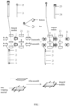
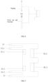
- a joint finger ring (as shown in Fig. 1 ) is composed of a ring setting 1, inlays 2 and connection components 3, wherein the inlays 2 are embedded into inlay wrapping materials to form an integral module to be arranged into the ring setting 1.
- the left end and the right end of the ring setting 1 are movably connected through the connection components 3.
- the ring setting 1 is similar to a watchband and can be bent, disassembled and assembled.
- the ring setting is composed of ring setting components 21, C-shaped pins 22 and C-shaped pipes 23 or fixed pins 24 and fixed caps 25.
- the fixed pin 24 can be correspondingly connected with the fixed cap 25.
- the fixed cap 25 can be correspondingly connected with the fixed pin 24.
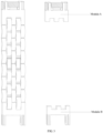
- the ring setting components 21 are modular components that can be disassembled and assembled into the appearance of the ring setting 1 (as shown in Fig. 7-Fig. 9 ).
- the inlays are embedded into the inlay wrapping materials to form the integral module to be arranged in the ring setting 1 (as shown in Fig. 8-Fig. 10 ).
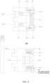
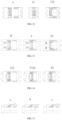
- connection component 3 is composed of a module A and a module B to form the movable connection (as shown in Fig. 12 and Fig. 17-Fig. 19).
- the module A includes a lock switch button 31, a return spring 32 or a return magnet 32-1 and a return magnet 32-2, module A joint bayonets 33-1, a fixed bulge or notch 34, a module A ring setting joint 35-1 or 35-2 and 35-3 (as shown in Fig. 13 ).
- the return spring 32 or the return magnet 32-1 and the return magnet 32-2 are located right below the tail of the module A lock switch button 31 (as shown in Fig. 13 ).
- the module A joint bayonets 33-1 are located at two sides of the lock switch button 31.
- the module A joint bayonet 33-1 is composed of a toothed opening, a toothed opening spring or a toothed opening return magnet 1, a toothed opening carrier rod and a movable knuckle (as shown in Fig. 13 ).
- the toothed opening is located in the toothed opening carrier rod and is a row of triangular movable exposed bayonets.
- the toothed opening carrier rod is connected with the lock switch button 31 through the movable knuckle.
- the movable knuckle is perpendicular to a position between the toothed opening carrier rod and the lock switch button 31 (as shown in Fig. 14-Fig. 15 ).
- the fixed bulge or notch 34 is located on the left end and the right end of the module A and is used for the up-down fixation of the module A and the module B at a connection state correspondingly together with the fixed notch or bulge 37 in the module B.
- the module A passes through the ring setting joint 35-1 to be connected with one end of the ring setting through an earplug or the module A is connected with one end of the ring setting through the connection of the ring setting joint 35-2 and the ring setting joint 35-32 and the fixed pin 34 and the fixed cap 35 (as shown in Fig. 13 ).
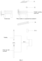
- the finger ring can be worn on the finger; and when the module A and the module B are separated by the user, the lock switch button 31 is pressed down; after the toothed opening carrier rod is pulled towards the inner side through the movable knuckle, the toothed opening is separated from a slot in the module B joint bayonets 33-2, thereby separating the module A and the module B (as shown in Fig. 17).
- the components in the module A and the module B are on fixed positions.
- the first joint bayonet 33-1 on the front end of the module A is connected with a connection position of the second joint bayonet 33-2 on the front end of the module B.
- the exposed toothed opening of the module A may be continuously pushed by the module A joint bayonets 33-2 to have a telescopic motion so as to be fixed in the longitudinal direction.
- the fixed bulge or notch 34 in the module A is correspondingly connected with the fixed notch or bulge 37 in the module B so as to fix the module A in the vertical direction and to adjust the feeling to the best state.
- the toothed opening is under the action of the toothed opening spring or the toothed opening return magnet 1.
- the toothed opening spring or the toothed opening return magnet 1 Through the toothed opening spring or the toothed opening return magnet 1, the triangular slot on the connection position of the joint bayonets 33-2 in the module B can be correspondingly connected with the toothed opening along with the connection action.
- the module A and the module B are correspondingly connected in the vertical and longitudinal directions, and each component in the module A is returned.
- the lock switch button 31 is pushed backwards first, and at this moment, the exposed toothed opening may be retracted inwards, so that the module A and the module B have no fixed connection in the longitudinal direction.
- each component in the module A is returned.
- this innovative design solves the problem that in the wearing process of the traditional finger rings, the size of the finger ring of the favorite style is appropriately increased at the beginning of selection or customization so as to fit the finger. As a result, it is impossible to achieve the best feeling when people wear the finger ring; and moreover, due to a lot of reasons, the finger ring may not be taken off, which is more obvious especially for the characteristics of male finger bones. Meanwhile, when the consumer needs the product of the same style with different appearances, only the corresponding accessories need to be added, so that the trouble for purchasing the whole product with the original structure can be avoided. Based on the market demand, this design incorporates the design concepts of ergonomics, overall aesthetics, ultra-thin standards, convenient use and feasible craftsmanship. The innovative design is made on the basis of the traditional concept of the existing finger ring, thereby providing technical and material basis to fill a gap in the market.
Landscapes
- Adornments (AREA)
Claims (4)
- ein Gelenkfingerring, der eine Ringeinstellung (1), Einlagerungen (2) und Verbindungskomponenten ts (3) umfasst, wobei die Einlagerungen (2) durch Einlagerumwickelmaterialien in der Ringeinstellung (1) angeordnet sind und das linke und das rechte Ende der Ringeinstellung (1) über die Verbindungskomponenten (3) beweglich verbunden sind;Die Ringeinstellung (1) ähnelt einem Uhrenband und kann gebogen, zerlegt und eingebaut werden. Sie besteht aus Ringeinstellung Komponenten (21), 2pc-Form 2 Stifte (22) und c-förmige Rohr(23) oder festen Kappen 2 P (24) 2 und fixierte 2 Pins (25); 2 pis,Die Einstellteile (21) bestehen aus einem Integralmodul und Edelmetallen aus Platin, Gold und Silber oder aus einem Integralmodul und gewöhnlichem Metall,Wobei die Verbindungskomponente (3) aus einem Modul a und einem Modul b zu einem formbeweglichen Verband bestehtDas Modul b umfasst einen zweiten magnetischen Stein- oder Magnet(35-2), einen zweiten Verbindungsbajonett (33-2), einen zweiten Ringverbindungsverbindung(36-2) und einen festen Kerb(37);Das Modul a umfasst einen Schalterknopf (31), eine Rückfeder (32), erste Verbindungsbajonette (33-1), eine festen Ausbauung (34), einen ersten Magnetstein oder Magnet (35-1) und einen ersten Ringverbindungsgelenk (36-1), der mit dem Modul a und einem Ende der Ringverbindungsstelle durch einen Ohrstopfer oder die festen Kappen und festen Stiften verbunden ist; Oder das Modul a enthält einen Schalterknopf (31), einen Rückgabemagneten (32-1), einen Rückgabemagneten (32-2), den ersten Verbindungsbajonett s (33-1), einen festen Ausbau(34), den ersten Magnetstein oder Magneten (35-1) und den ersten Ringeinstellungsgelenk (36-1), der erste Ringeinstellungsgelenk (36-1) besteht, der Ohrstopper oder die festen Stifte und die festen Kappen besteht, um die Mündung mit einem und einem Ende des Ringeinstellungsgelenks zu verbinden; UndDiese zweite Ringeinstellungsstecke (36-2) befindet sich auf der linken und rechten Seite des unteren Endes des Moduls b und ist mit dem Modul b und dem anderen Ende der Ringeinstellung durch den Ohrstecker oder die festen Kappen und festen Stiften verbunden, wobei die zweite Ringeinstellungsstecke (36-2) aus dem Ohrstecker oder den festen Kappen und festen Stiften besteht.
- Der Verbindungsfingerring gemäß Anspruch 1, wobei die Einlagerungen (2) in die Einlagerumwickelmaterialien eingebettet sind, um ein integrales Modul zu bilden, das in der Einstellung (1) angeordnet ist.
- Der Gelenkfingerring gemäß Anspruch 1, wobei die Ringeinstellungskomponenten (21) Module sind, die in die Ansicht des Ringeinstellungsstücks (1) zerlegt und montiert werden können, und
Bestehend aus Edelmetallen, Ordinametallen oder einem integrierten Modul, das aus den Einlageund den Einlageumschließungsmaterialien besteht. - Der Verbindungsfingerring gemäß Anspruch 1, wobei das Modul a den Schalttaster (31), die Rennfeder (32), die ersten Verbindungsbajonette (33-1), die festen Ausbauungen (34), den ersten Magnetstein oder Magnet (35-1) und den ersten Ringverbindungsgelenk (36-1) enthält;Die Schalttaste (31) zum beweglichen Trennen des Moduls a und des Moduls b befindet sich in der Mitte des gesamten Moduls a;Die Rückfeder 32 liegt direkt unter dem Schwanz der Modulschaltertaste 31;Die ersten Gelenkbajonette(33-1) sind an zwei Seiten des Schalterknopfes (31) befindet, und jeder erste Gelenkbajonette(33-1) besteht aus einer gezahnten Öffnung, einer gezahnten Öffnungsfeder, einer gezahnten Öffnungsfeder und einem beweglichen Knöchel.WobeiDie Zahnöffnung befindet sich in der Zahnöffnungsträgerstange und ist eine Reihe dreieckiger beweglicher freigelegter Bajonette; Die gezahnte Öffnungsfeder befindet sich in der gezahnten Öffnung und verbunden mit der gezahnten Öffnungsfeder und der gezahnten Öffnungsträgerstange der rauen abarrel förmigen Hohlsäule an der Vorderseite;Die gezahnte Öffnungsträgerstange ist durch einen beweglichen Knochel mit der Verriegelungsschalttaste (31) verbunden, und der bewegliche Knochel ist senkrecht zu einer Position zwischen dem gezahnten Öffnungsträgerstange und der Verriegelungsschalttaste (31);Die festgelegte Ausbau(34) befindet sich auf der linken und rechten Ende des Moduls a und entspricht der festgelegten Ausbau(37) im Modul b; UndWenn das Modul a den Schalttaster (31), den Rückgabemagneten (32-1), den Rückgabemagneten (32-2), die ersten Verbindungsbajonette (33-1), die festen Ausbauungen (34), den Tannenmagneten (35-1) und die erste Einstellungsverbindung (36-1) enthält;Der Schalttaster (31) zum beweglichen Trennen des Moduls a und des Moduls b befindet sich in der Mitte des gesamten Moduls a;Der Rückkehrmagnet (32-1) befindet sich innerhalb des Moduls mit einer Schalttaste (31) und spielt eine Rolle bei der Abwehrung des Rückkehrmagnets (32-2) aufgrund ähnlicher Polaritäten;Der Rückkehrmagnet (32-2) befindet sich im mittleren Teil des Moduls a und spielt eine Rolle, den Rückkehrmagnet (32-1) aufgrund ähnlicher Polaritäten abzuwehren;Die ersten Gelenkbajonette(33-1) befinden sich an zwei Seiten des Schalttasters (31) und jeder erste Gelenkbajonette(33-1) besteht aus einer gezahnten Öffnung, einem gezahnten Öffnungsmagneten (1), einem gezahnten Magneten (2), einem beweglichen Knöchelträgerstab (38) und einem beweglichen Knöchel.Wobei die Zahnöffnung an einem Ende des beweglichen Knöchels, einer Reihe dreieckiger beweglicher freigelegter Bajonette, befindet und durch eine zylindrische Hohlsäule am vorderen Ende mit dem m-Knöchel a festverbunden ist und durch eine zylindrische Hohlsäule in der Zahnöffnung mit einem Ende des beweglichen Knöchels festverbunden ist;Das bewegliche Knochel zwischen der Zahnöffnung und dem beweglichen Knochelträgerstab (38); Ein Ende mit der Zahnöffnung und ein Ende mit der beweglichen Knöchelträgerstange 38 verbunden, wobei der Zahnöffnungs-Rückmagnet (1) auf dem beweglichen Knöchel befindet und den Zahnmagnet (2) aufgrund ähnlicher Polaritäten abweist;Die bewegliche Knochelträgerstange (38) befindet sich zwischen dem beweglichen Knochel und dem Verriegelungsschalter (31), wobei der gezahnte Magnet (2) in der beweglichen Knochelträgerstange (38) befindet und aufgrund ähnlicher Polaritäten eine Rolle dabei spielt, den gezahnten Öffnungsrückmagnet (1) abzuwehren;Die festgelegte Ausbau(34) befindet sich auf der linken und rechten Ende des Moduls a und entspricht der festgelegten Ausbau(37) im Modul b; UndDer zweite magnetische Stein- oder Magnet(35-2) entspricht dem ersten magnetischen Stein- oder Magnet(35-1) im Modul;Die festgelegte Kerbe (37) befindet sich am linken und rechten Ende des Moduls b und entspricht der festgelegten Ausbauung (34) in den Modulen a;Das zweite Gelenkbajonett (33-2) befindet sich auf zwei Würfeln an den oberen Innenseiten des Moduls b, das Würfeln im Inneren umfasst eine Reihe freigelegter Dreieckniederschläge; Und die dreieckigen Aussätze sind entsprechend mit der Zahnöffnung im ersten Gelenkbajonett (33-1) des Moduls a verbunden.
Applications Claiming Priority (1)
| Application Number | Priority Date | Filing Date | Title |
|---|---|---|---|
| PCT/CN2018/093810 WO2020000420A1 (zh) | 2018-06-29 | 2018-06-29 | 一种接口式戒指 |
Publications (4)
| Publication Number | Publication Date |
|---|---|
| EP3815565A1 EP3815565A1 (de) | 2021-05-05 |
| EP3815565A4 EP3815565A4 (de) | 2022-03-23 |
| EP3815565B1 true EP3815565B1 (de) | 2025-02-19 |
| EP3815565C0 EP3815565C0 (de) | 2025-02-19 |
Family
ID=68984601
Family Applications (1)
| Application Number | Title | Priority Date | Filing Date |
|---|---|---|---|
| EP18924797.6A Active EP3815565B1 (de) | 2018-06-29 | 2018-06-29 | Gelenkartiger ring |
Country Status (3)
| Country | Link |
|---|---|
| US (1) | US11369171B2 (de) |
| EP (1) | EP3815565B1 (de) |
| WO (1) | WO2020000420A1 (de) |
Families Citing this family (2)
| Publication number | Priority date | Publication date | Assignee | Title |
|---|---|---|---|---|
| CN112137255A (zh) * | 2020-10-09 | 2020-12-29 | 盈利时表业(东莞)有限公司 | 一种易拆装型结构及其带有该易拆装型结构的表带 |
| EP4298948B1 (de) * | 2022-06-30 | 2025-02-26 | Comadur S.A. | Armband mit kettengliedern aus hartem material |
Family Cites Families (12)
| Publication number | Priority date | Publication date | Assignee | Title |
|---|---|---|---|---|
| FR568919A (fr) * | 1923-07-21 | 1924-04-03 | Bague sertie tout autour pouvant s'agrandir à volonté | |
| JPS5348157Y2 (de) * | 1976-06-22 | 1978-11-17 | ||
| US4158951A (en) * | 1977-05-11 | 1979-06-26 | Cedar Samuel N | Ring or bracelet having pivoted locking clasp |
| CH697560B1 (fr) * | 2003-08-27 | 2008-11-28 | Pierre Salanitro | Pièce de bijouterie à maillons articulés, notamment un bracelet, un collier ou un bracelet-montre. |
| CN101642314A (zh) * | 2009-08-27 | 2010-02-10 | 苏州工业园区博友钛钢科技有限公司 | 一种手链 |
| GB2475065B (en) | 2009-11-04 | 2012-04-04 | Vector Int Ltd | Seal ring and joint |
| CN201822079U (zh) * | 2010-07-20 | 2011-05-11 | 吴瑞熙 | 一种球形自锁磁吸扣 |
| US9809047B2 (en) | 2013-02-18 | 2017-11-07 | U.S. Ring Binder, L.P. | Ring lock guard for a ring binder |
| CN104490023B (zh) * | 2014-12-18 | 2017-05-03 | 赵威 | 互换式扭钉首饰锁扣 |
| CN205410010U (zh) * | 2016-02-17 | 2016-08-03 | 李原林 | 一种可自由调节手寸的戒指 |
| CN205432434U (zh) * | 2016-03-22 | 2016-08-10 | 高孝品 | 表带快拆结构 |
| CN107041609B (zh) * | 2017-05-03 | 2019-01-18 | 兴固五金(深圳)有限公司 | 一种表带的简易拆装结构及手表 |
-
2018
- 2018-06-29 EP EP18924797.6A patent/EP3815565B1/de active Active
- 2018-06-29 WO PCT/CN2018/093810 patent/WO2020000420A1/zh not_active Ceased
-
2020
- 2020-10-01 US US17/060,200 patent/US11369171B2/en active Active
Also Published As
| Publication number | Publication date |
|---|---|
| US11369171B2 (en) | 2022-06-28 |
| EP3815565A4 (de) | 2022-03-23 |
| WO2020000420A1 (zh) | 2020-01-02 |
| EP3815565C0 (de) | 2025-02-19 |
| US20210015221A1 (en) | 2021-01-21 |
| EP3815565A1 (de) | 2021-05-05 |
Similar Documents
| Publication | Publication Date | Title |
|---|---|---|
| EP3815565B1 (de) | Gelenkartiger ring | |
| KR102069057B1 (ko) | 제작단가가 절감되면서 볼륨감이 있는 펜던트 제조방법 | |
| KR200485628Y1 (ko) | 조립형 목걸이 세트 | |
| KR200471068Y1 (ko) | 의류에 사용하는 장식물 | |
| KR200469408Y1 (ko) | 조립식 액세서리용 팬던트 | |
| WO2012066584A1 (en) | Ring with interchangeable interlocking elements | |
| CN208387996U (zh) | 一种接口件 | |
| KR102537047B1 (ko) | 반지 및 목걸이로 가변되는 장신구 | |
| CN222367244U (zh) | 一种多层组合、拆卸并可调节尺寸的首饰结构 | |
| CN211048576U (zh) | 一种新型的具有两种佩戴方式的珠宝结构 | |
| JP2025066859A (ja) | バンド | |
| US20050172669A1 (en) | Ornamental item with variable configuration, and method for its manufacture | |
| KR101150835B1 (ko) | 코디 귀걸이 | |
| CN223452891U (zh) | 一种组合式手镯 | |
| CN212852735U (zh) | 一种定位装置 | |
| CN207626700U (zh) | 一种接口式戒指 | |
| KR200397718Y1 (ko) | 조립식 반지 | |
| KR200252416Y1 (ko) | 악세사리용 장신구 | |
| KR200380796Y1 (ko) | 형태 변형이 가능한 목걸이용 펜던트 | |
| KR200463726Y1 (ko) | 장식부가 가변이 되는 펜던트 | |
| JP3194596U (ja) | スライドによるコンビネーション装身具 | |
| KR200360664Y1 (ko) | 다기능 장신구 | |
| KR200339649Y1 (ko) | 장신구용 펜던트 | |
| CN206333475U (zh) | 一种无焊点拼接首饰 | |
| KR20170037340A (ko) | 조립형 목걸이 세트 |
Legal Events
| Date | Code | Title | Description |
|---|---|---|---|
| STAA | Information on the status of an ep patent application or granted ep patent |
Free format text: STATUS: THE INTERNATIONAL PUBLICATION HAS BEEN MADE |
|
| PUAI | Public reference made under article 153(3) epc to a published international application that has entered the european phase |
Free format text: ORIGINAL CODE: 0009012 |
|
| STAA | Information on the status of an ep patent application or granted ep patent |
Free format text: STATUS: REQUEST FOR EXAMINATION WAS MADE |
|
| 17P | Request for examination filed |
Effective date: 20210129 |
|
| AK | Designated contracting states |
Kind code of ref document: A1 Designated state(s): AL AT BE BG CH CY CZ DE DK EE ES FI FR GB GR HR HU IE IS IT LI LT LU LV MC MK MT NL NO PL PT RO RS SE SI SK SM TR |
|
| DAV | Request for validation of the european patent (deleted) | ||
| DAX | Request for extension of the european patent (deleted) | ||
| A4 | Supplementary search report drawn up and despatched |
Effective date: 20220217 |
|
| RIC1 | Information provided on ipc code assigned before grant |
Ipc: A44C 5/10 20060101ALN20220211BHEP Ipc: A44C 5/20 20060101ALI20220211BHEP Ipc: A44C 11/02 20060101ALI20220211BHEP Ipc: A44C 5/14 20060101ALI20220211BHEP Ipc: A44C 9/02 20060101AFI20220211BHEP |
|
| GRAP | Despatch of communication of intention to grant a patent |
Free format text: ORIGINAL CODE: EPIDOSNIGR1 |
|
| RIC1 | Information provided on ipc code assigned before grant |
Ipc: A44C 5/10 20060101ALN20241008BHEP Ipc: A44C 5/20 20060101ALI20241008BHEP Ipc: A44C 11/02 20060101ALI20241008BHEP Ipc: A44C 5/14 20060101ALI20241008BHEP Ipc: A44C 9/02 20060101AFI20241008BHEP |
|
| STAA | Information on the status of an ep patent application or granted ep patent |
Free format text: STATUS: GRANT OF PATENT IS INTENDED |
|
| RIC1 | Information provided on ipc code assigned before grant |
Ipc: A44C 5/10 20060101ALN20241024BHEP Ipc: A44C 5/20 20060101ALI20241024BHEP Ipc: A44C 11/02 20060101ALI20241024BHEP Ipc: A44C 5/14 20060101ALI20241024BHEP Ipc: A44C 9/02 20060101AFI20241024BHEP |
|
| INTG | Intention to grant announced |
Effective date: 20241114 |
|
| GRAS | Grant fee paid |
Free format text: ORIGINAL CODE: EPIDOSNIGR3 |
|
| GRAA | (expected) grant |
Free format text: ORIGINAL CODE: 0009210 |
|
| STAA | Information on the status of an ep patent application or granted ep patent |
Free format text: STATUS: THE PATENT HAS BEEN GRANTED |
|
| AK | Designated contracting states |
Kind code of ref document: B1 Designated state(s): AL AT BE BG CH CY CZ DE DK EE ES FI FR GB GR HR HU IE IS IT LI LT LU LV MC MK MT NL NO PL PT RO RS SE SI SK SM TR |
|
| REG | Reference to a national code |
Ref country code: GB Ref legal event code: FG4D |
|
| REG | Reference to a national code |
Ref country code: CH Ref legal event code: EP |
|
| REG | Reference to a national code |
Ref country code: IE Ref legal event code: FG4D |
|
| REG | Reference to a national code |
Ref country code: DE Ref legal event code: R096 Ref document number: 602018079466 Country of ref document: DE |
|
| U01 | Request for unitary effect filed |
Effective date: 20250306 |
|
| U07 | Unitary effect registered |
Designated state(s): AT BE BG DE DK EE FI FR IT LT LU LV MT NL PT RO SE SI Effective date: 20250314 |
|
| U20 | Renewal fee for the european patent with unitary effect paid |
Year of fee payment: 8 Effective date: 20250528 |
|
| PG25 | Lapsed in a contracting state [announced via postgrant information from national office to epo] |
Ref country code: RS Free format text: LAPSE BECAUSE OF FAILURE TO SUBMIT A TRANSLATION OF THE DESCRIPTION OR TO PAY THE FEE WITHIN THE PRESCRIBED TIME-LIMIT Effective date: 20250519 |
|
| PG25 | Lapsed in a contracting state [announced via postgrant information from national office to epo] |
Ref country code: PL Free format text: LAPSE BECAUSE OF FAILURE TO SUBMIT A TRANSLATION OF THE DESCRIPTION OR TO PAY THE FEE WITHIN THE PRESCRIBED TIME-LIMIT Effective date: 20250219 |
|
| PG25 | Lapsed in a contracting state [announced via postgrant information from national office to epo] |
Ref country code: ES Free format text: LAPSE BECAUSE OF FAILURE TO SUBMIT A TRANSLATION OF THE DESCRIPTION OR TO PAY THE FEE WITHIN THE PRESCRIBED TIME-LIMIT Effective date: 20250219 |
|
| PGFP | Annual fee paid to national office [announced via postgrant information from national office to epo] |
Ref country code: GB Payment date: 20250625 Year of fee payment: 8 |
|
| PG25 | Lapsed in a contracting state [announced via postgrant information from national office to epo] |
Ref country code: IS Free format text: LAPSE BECAUSE OF FAILURE TO SUBMIT A TRANSLATION OF THE DESCRIPTION OR TO PAY THE FEE WITHIN THE PRESCRIBED TIME-LIMIT Effective date: 20250619 Ref country code: NO Free format text: LAPSE BECAUSE OF FAILURE TO SUBMIT A TRANSLATION OF THE DESCRIPTION OR TO PAY THE FEE WITHIN THE PRESCRIBED TIME-LIMIT Effective date: 20250519 |
|
| PG25 | Lapsed in a contracting state [announced via postgrant information from national office to epo] |
Ref country code: HR Free format text: LAPSE BECAUSE OF FAILURE TO SUBMIT A TRANSLATION OF THE DESCRIPTION OR TO PAY THE FEE WITHIN THE PRESCRIBED TIME-LIMIT Effective date: 20250219 |
|
| PG25 | Lapsed in a contracting state [announced via postgrant information from national office to epo] |
Ref country code: GR Free format text: LAPSE BECAUSE OF FAILURE TO SUBMIT A TRANSLATION OF THE DESCRIPTION OR TO PAY THE FEE WITHIN THE PRESCRIBED TIME-LIMIT Effective date: 20250520 |
|
| PG25 | Lapsed in a contracting state [announced via postgrant information from national office to epo] |
Ref country code: SM Free format text: LAPSE BECAUSE OF FAILURE TO SUBMIT A TRANSLATION OF THE DESCRIPTION OR TO PAY THE FEE WITHIN THE PRESCRIBED TIME-LIMIT Effective date: 20250219 |
|
| PGFP | Annual fee paid to national office [announced via postgrant information from national office to epo] |
Ref country code: CH Payment date: 20250701 Year of fee payment: 8 |
|
| PG25 | Lapsed in a contracting state [announced via postgrant information from national office to epo] |
Ref country code: CZ Free format text: LAPSE BECAUSE OF FAILURE TO SUBMIT A TRANSLATION OF THE DESCRIPTION OR TO PAY THE FEE WITHIN THE PRESCRIBED TIME-LIMIT Effective date: 20250219 |
|
| PG25 | Lapsed in a contracting state [announced via postgrant information from national office to epo] |
Ref country code: SK Free format text: LAPSE BECAUSE OF FAILURE TO SUBMIT A TRANSLATION OF THE DESCRIPTION OR TO PAY THE FEE WITHIN THE PRESCRIBED TIME-LIMIT Effective date: 20250219 |
|
| PLBE | No opposition filed within time limit |
Free format text: ORIGINAL CODE: 0009261 |
|
| STAA | Information on the status of an ep patent application or granted ep patent |
Free format text: STATUS: NO OPPOSITION FILED WITHIN TIME LIMIT |
|
| REG | Reference to a national code |
Ref country code: CH Ref legal event code: L10 Free format text: ST27 STATUS EVENT CODE: U-0-0-L10-L00 (AS PROVIDED BY THE NATIONAL OFFICE) Effective date: 20251231 |
|
| 26N | No opposition filed |
Effective date: 20251120 |
|
| PG25 | Lapsed in a contracting state [announced via postgrant information from national office to epo] |
Ref country code: MC Free format text: LAPSE BECAUSE OF FAILURE TO SUBMIT A TRANSLATION OF THE DESCRIPTION OR TO PAY THE FEE WITHIN THE PRESCRIBED TIME-LIMIT Effective date: 20250219 |