EP3815504A1 - String trimmer with pole break - Google Patents
String trimmer with pole break Download PDFInfo
- Publication number
- EP3815504A1 EP3815504A1 EP20202820.5A EP20202820A EP3815504A1 EP 3815504 A1 EP3815504 A1 EP 3815504A1 EP 20202820 A EP20202820 A EP 20202820A EP 3815504 A1 EP3815504 A1 EP 3815504A1
- Authority
- EP
- European Patent Office
- Prior art keywords
- pole
- pole section
- string trimmer
- battery
- hinge
- Prior art date
- Legal status (The legal status is an assumption and is not a legal conclusion. Google has not performed a legal analysis and makes no representation as to the accuracy of the status listed.)
- Granted
Links
- 230000001681 protective effect Effects 0.000 abstract description 3
- 238000000034 method Methods 0.000 description 2
- 230000000903 blocking effect Effects 0.000 description 1
- 230000007246 mechanism Effects 0.000 description 1
- 238000012986 modification Methods 0.000 description 1
- 230000004048 modification Effects 0.000 description 1
Images


Classifications
-
- A—HUMAN NECESSITIES
- A01—AGRICULTURE; FORESTRY; ANIMAL HUSBANDRY; HUNTING; TRAPPING; FISHING
- A01D—HARVESTING; MOWING
- A01D34/00—Mowers; Mowing apparatus of harvesters
- A01D34/835—Mowers; Mowing apparatus of harvesters specially adapted for particular purposes
- A01D34/90—Mowers; Mowing apparatus of harvesters specially adapted for particular purposes for carrying by the operator
-
- A—HUMAN NECESSITIES
- A01—AGRICULTURE; FORESTRY; ANIMAL HUSBANDRY; HUNTING; TRAPPING; FISHING
- A01D—HARVESTING; MOWING
- A01D34/00—Mowers; Mowing apparatus of harvesters
- A01D34/01—Mowers; Mowing apparatus of harvesters characterised by features relating to the type of cutting apparatus
- A01D34/412—Mowers; Mowing apparatus of harvesters characterised by features relating to the type of cutting apparatus having rotating cutters
- A01D34/63—Mowers; Mowing apparatus of harvesters characterised by features relating to the type of cutting apparatus having rotating cutters having cutters rotating about a vertical axis
- A01D34/67—Mowers; Mowing apparatus of harvesters characterised by features relating to the type of cutting apparatus having rotating cutters having cutters rotating about a vertical axis hand-guided by a walking operator
- A01D34/68—Mowers; Mowing apparatus of harvesters characterised by features relating to the type of cutting apparatus having rotating cutters having cutters rotating about a vertical axis hand-guided by a walking operator with motor driven cutters or wheels
-
- A—HUMAN NECESSITIES
- A01—AGRICULTURE; FORESTRY; ANIMAL HUSBANDRY; HUNTING; TRAPPING; FISHING
- A01D—HARVESTING; MOWING
- A01D34/00—Mowers; Mowing apparatus of harvesters
- A01D34/01—Mowers; Mowing apparatus of harvesters characterised by features relating to the type of cutting apparatus
- A01D34/412—Mowers; Mowing apparatus of harvesters characterised by features relating to the type of cutting apparatus having rotating cutters
- A01D34/416—Flexible line cutters
-
- A—HUMAN NECESSITIES
- A01—AGRICULTURE; FORESTRY; ANIMAL HUSBANDRY; HUNTING; TRAPPING; FISHING
- A01D—HARVESTING; MOWING
- A01D34/00—Mowers; Mowing apparatus of harvesters
- A01D34/01—Mowers; Mowing apparatus of harvesters characterised by features relating to the type of cutting apparatus
- A01D34/412—Mowers; Mowing apparatus of harvesters characterised by features relating to the type of cutting apparatus having rotating cutters
- A01D34/63—Mowers; Mowing apparatus of harvesters characterised by features relating to the type of cutting apparatus having rotating cutters having cutters rotating about a vertical axis
- A01D34/76—Driving mechanisms for the cutters
- A01D34/78—Driving mechanisms for the cutters electric
-
- A—HUMAN NECESSITIES
- A01—AGRICULTURE; FORESTRY; ANIMAL HUSBANDRY; HUNTING; TRAPPING; FISHING
- A01D—HARVESTING; MOWING
- A01D34/00—Mowers; Mowing apparatus of harvesters
- A01D34/01—Mowers; Mowing apparatus of harvesters characterised by features relating to the type of cutting apparatus
- A01D34/412—Mowers; Mowing apparatus of harvesters characterised by features relating to the type of cutting apparatus having rotating cutters
- A01D34/63—Mowers; Mowing apparatus of harvesters characterised by features relating to the type of cutting apparatus having rotating cutters having cutters rotating about a vertical axis
- A01D34/82—Other details
- A01D34/824—Handle arrangements
-
- F—MECHANICAL ENGINEERING; LIGHTING; HEATING; WEAPONS; BLASTING
- F16—ENGINEERING ELEMENTS AND UNITS; GENERAL MEASURES FOR PRODUCING AND MAINTAINING EFFECTIVE FUNCTIONING OF MACHINES OR INSTALLATIONS; THERMAL INSULATION IN GENERAL
- F16C—SHAFTS; FLEXIBLE SHAFTS; ELEMENTS OR CRANKSHAFT MECHANISMS; ROTARY BODIES OTHER THAN GEARING ELEMENTS; BEARINGS
- F16C11/00—Pivots; Pivotal connections
- F16C11/04—Pivotal connections
- F16C11/10—Arrangements for locking
-
- G—PHYSICS
- G06—COMPUTING; CALCULATING OR COUNTING
- G06F—ELECTRIC DIGITAL DATA PROCESSING
- G06F9/00—Arrangements for program control, e.g. control units
- G06F9/06—Arrangements for program control, e.g. control units using stored programs, i.e. using an internal store of processing equipment to receive or retain programs
- G06F9/44—Arrangements for executing specific programs
- G06F9/445—Program loading or initiating
-
- H—ELECTRICITY
- H04—ELECTRIC COMMUNICATION TECHNIQUE
- H04N—PICTORIAL COMMUNICATION, e.g. TELEVISION
- H04N1/00—Scanning, transmission or reproduction of documents or the like, e.g. facsimile transmission; Details thereof
- H04N1/32—Circuits or arrangements for control or supervision between transmitter and receiver or between image input and image output device, e.g. between a still-image camera and its memory or between a still-image camera and a printer device
- H04N1/32502—Circuits or arrangements for control or supervision between transmitter and receiver or between image input and image output device, e.g. between a still-image camera and its memory or between a still-image camera and a printer device in systems having a plurality of input or output devices
- H04N1/32545—Distributing a job or task among a plurality of input devices or a plurality of output devices
- H04N1/3255—Hybrid jobs, i.e. performing different parts of the same job on different devices, e.g. colour and B/W pages on different devices
Definitions
- the present invention is directed to a string trimmer having a hinged pole allowing the tool to be folded for easy transport and storage.
- String trimmers are common outdoor tools that typically have a long pole with a cutting head on an end and a handle at the other.
- the cutting head includes a filament line or other cutting element that is rotated at high speed to cut vegetation.
- removable batteries are usually provided in the handle with a motor located in the cutting head. To deliver power to the motor, an electrical cable is run from the battery through the pole to the motor.
- An aspect of the present invention is directed to a poled string trimmer having a first end with cutting head and motor, and a second end having a handle with a battery housing for receiving a removable and rechargeable battery.
- the pole includes a rotatable hinge for allowing the string trimmer to be folded, and an electrical cable connecting the battery housing and the motor is run through the hinge.
- the hinge includes a hub with an opening, allowing the cable to be wired through an interior space of the hub. The pole and hinge therefore provide a protective covering for the electrical cable.
- the hub also reduces the chance that the electrical cable will be "pinched" and damaged by the pole halves.
- An embodiment of the invention includes a latch that locks the hinge in a straight configuration.
- the latch is preferably an over-center latch, that includes a lever with an inset tab.
- the tab rotates with respect to the lever and engages a hook to prevent the lever from moving from the locked to the unlocked position.
- the tab provides a safety feature to prevent accidental release of the lever.
- a further embodiment of the invention includes a guard on the cutting head.
- the guard's primary function is to shield user from flying debris launched by the cutting head.
- the guard blocks the battery so that the string trimmer cannot be fully folded.
- the battery housing can move past the guard into the fully folded position.
- the guard includes a contact surface that engages the battery housing to secure the string trimmer in the folded position.
- a string trimmer comprising: a pole having a first end with cutting head, the cutting head having a motor housing and a motor, the pole having a second end having a handle and a battery housing; the pole having a first pole section and a second pole section, the cutting head being on the first pole section and the handle on the second pole section; wherein the first pole section and the second pole section are connected by a hinge allowing the string trimmer to be moved from a straight configuration to a folded configuration; and an electrical cable connecting the battery housing and the motor, the electrical cable being run through the first pole section, the hinge, and the second pole section.
- the hinge may have a first socket for receiving the first pole section and a second socket for receiving the second pole section.
- the string trimmer may further include a latch that locks the hinge so that the poles are in the straight configuration.
- the latch may include a bracket on the first socket and a lever on the second socket.
- the lever may include a tab to lock the lever in a locked position.
- the hinge may include a hub for rotatably connecting the first and second socket, and the hub has an opening through which the electrical cable passes.
- the string trimmer may further include a guard on the motor housing, wherein when a battery is inserted in the battery housing the guard is adapted to contact the battery to prevent the string trimmer from being fully folded.
- the guard may include a retaining feature that secures the battery housing to the guard when the battery is removed from the battery housing.
- the hinge may keep the electrical cable covered in both the folded and straight configuration.
- a poled cutting device comprising: a pole having a first end and a second end; a cutting implement, a motor housing and a motor in the motor housing on the first end of the pole; a handle and a battery housing on the second end of the pole; the pole including a first pole section and a second pole section, and a hinge connecting the first pole section to the second pole section allowing the pole to be folded; an electrical cable connecting the battery housing to the motor, the electrical cable being contained within the first pole section, second pole section and hinge.
- the string trimmer may further comprise a guard on the motor housing, the guard adapted to block a battery inserted into the battery housing to prevent the cutting device from being fully folded.
- the guard may include a retaining feature for securing the battery housing when no battery is inserted, to hold the string trimmer in a folded position.
- the retaining feature may comprise an interference surface that frictionally holds the battery housing.
- the hinge may include a hub for rotatably connecting the first pole section to the second pole section, the hub including an opening to allow the electrical cable to pass through.
- the string trimmer may further include a latch for locking the first pole section to the second pole section in a straight configuration, the latch including a lever to lock the latch, the lever including a tab to lock the lever in a locked position.
- the lever may include a slot, and the tab is rotatably positioned in the slot.
- Fig. 1 shows a string trimmer of the present invention.
- the string trimmer 10 includes a cutting head 12 at a first end of a pole 14.
- a second end of the pole 14 includes a main handle 16 with a power trigger 20.
- An auxiliary handle 18 is positioned forward of the main handle 16 to provide the user with greater control.
- a battery housing 23 is located at the rear of the pole and receives a battery 22 (see Figs. 3 and 4 ).
- the battery 22 provides power to a motor in the cutting head and is removable and rechargeable.
- any power source may be used and fall within the scope of the invention, including but not limited to electrical power through a cord or a gas engine.
- the cutting head 12 has a motor housing 24 that encloses the motor.
- a spool housing 26 is operatively connected to the motor.
- the spool housing encloses a spool with cutting line wound thereon.
- the cutting line extends out of the spool housing, and as the motor rotates the spool housing 26, the cutting line is rotated to cut vegetation.
- a guard 28 extends rearwardly from the motor housing 24 to provide a protective shield for the user, blocking any debris that may be thrown by the cutting line.
- a hinge 30 is Along a middle section of the pole 14.
- the hinge 30 allows the pole to be folded for easier transportation and storage.
- Fig. 3 shows the string trimmer partially folded but blocked by the battery 22
- Fig. 4 shows the battery 22 removed from the battery housing 23
- Fig. 5 shows the trimmer fully folded.
- the hinge 30 is made up of two arms 32 and 34 that are rotatably attached.
- the arms receive respective pole sections, with the lower pole section 14a inserted into arm 32 and the upper pole section 14b inserted into arm 34.
- Fig. 6 shows an exploded view of the hinge 30.
- the arm 34 includes a socket 38 for receiving the pole section 14b, and a hub 40 for rotatable connection with the other arm 32.
- Arm 32 is formed from two clamshell housings 32a and 32b which together form a socket 36 for receiving the pole 14a.
- the clamshells are secured through fasteners 39.
- the clamshells also form an axle housing 42 having an axle 43 that extends through the hub 40, and connects the two arms 32 and 34 together.
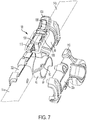
- Fig. 7 shows the hinge 30 partially assembled, with the clamshell 32a removed for clarity.
- an embodiment of the invention uses a battery 22 to power the string trimmer and an electrical cable 50 runs through the pole 14 from the battery housing 23 to the motor.
- the cable 50 travels down the pole section 14b and enters the hub 40 through an opening 46 (seen in Figs. 8 and 9 ).
- a portion of the hub 40 is cutout 44 so that the wire 50 can be bent around the hub and back into pole section 14a.
- the cutout 44 create a slot between the hub 40 and the clamshell 32a for the cable 50 to move in when the pole is folded.
- the hinge design 30 provides for the electrical cable 50 to be covered at all times and so protected from the environment. Furthermore, the hub 40 reduces the likelihood of "pinching" by the pole sections 14a and 14b, and provides for greater reliability during repeated folding and unfolding, thus eliminating the need for special sheathing for the cable.
- a latch 100 is provided to lock the hinge in a straight configuration.
- the latch 100 includes a pair of arms 101 that are secured to a receiving block 105 on the socket 38 using a pin 103.
- the latch 100 includes a lever 104 that is pivotable with respect to the block 105.
- a U-shaped wire loop 108 is secured to the lever 104 and a tab 106 is pivotably secured in a slot in the lever 104.
- An L-shaped bracket 110 is located opposite block 105 on arm 32, so that when the arms 32 and 34 are brought together, the bracket 110 abuts the block 105.
- Figs. 10-14 show the locking and unlocking of the latch 100.
- Figs. 10 and 11 show the latch 100 in a locked position, with Fig. 11 showing a partial sectional view showing the tab 106 secured to a hook 112.
- Fig. 12 then shows the tab 106 pivoted to release it from the hook 112, allowing the lever 104 to be raised.
- Fig. 13 shows the lever 104 raised, which moves the loop 108 forward so that it releases from the bracket 110, allowing the two arms 32 and 34 to be separated and the pole folded.
- the process is reversed.
- the loop 108 is placed around the bracket 110 and the lever 104 is rotated down so that the loop 108 is secured around the bracket 110.
- the tab 106 is then rotated so that it locks with the hook 112. Although the lever 104 would normally stay in the locked position, the tab 106 provides a backup to prevent accidental release of the lever 104.
- an over-center latch is shown, it should be understood that other locking mechanisms could be used to secure the pole sections together and still fall within the scope of the invention.
- Fig. 3 shows a battery 22 inserted into the battery housing 23, and a rearmost part of the battery 22 extending beyond the housing 23 to block the guard 28 and prevent the tool from fully folding. The user would then be alerted to the fact that the battery is still inserted and the string trimmer may be accidently turned on.
- Fig. 4 shows the battery 22 removed from the battery housing 23, which allows the guard 28 to move past the battery housing 23.
- Fig. 5 shows the battery housing 23 secured to the guard 28.
- Fig. 5A shows a closeup of the engagement between the guard 28 and the battery housing 23.
- the guard 28 includes a retaining feature or cut-out 120 that provides a catch for a lip 122 of the battery receptacle 23.
- the lip 122 rides over the edge of the cut-out 120 and comes to rest at its bottommost portion and holds the guard 28 in the folded position.
Landscapes
- Engineering & Computer Science (AREA)
- Environmental Sciences (AREA)
- Life Sciences & Earth Sciences (AREA)
- General Engineering & Computer Science (AREA)
- Software Systems (AREA)
- Theoretical Computer Science (AREA)
- Signal Processing (AREA)
- Multimedia (AREA)
- Mechanical Engineering (AREA)
- Physics & Mathematics (AREA)
- General Physics & Mathematics (AREA)
- Harvester Elements (AREA)
- Battery Mounting, Suspending (AREA)
Abstract
Description
- The present invention is directed to a string trimmer having a hinged pole allowing the tool to be folded for easy transport and storage.
- String trimmers are common outdoor tools that typically have a long pole with a cutting head on an end and a handle at the other. The cutting head includes a filament line or other cutting element that is rotated at high speed to cut vegetation. In the case of cordless string trimmers, removable batteries are usually provided in the handle with a motor located in the cutting head. To deliver power to the motor, an electrical cable is run from the battery through the pole to the motor.
- Many string trimmers have a single integral pole which provides the cheapest and simplest tool. However, the length of the pole can make them unwieldy and increase shipping costs for manufacturers. To address this issue, some manufacturers use two separate poles that users must assemble before first use. Oftentimes these poles are designed to be assembled only once when first used and are not easily taken apart. The makes transport and storage difficult for the user, or requires him to go through the cumbersome process of disassembling the string trimmer.
- Therefore, there is a need for a string trimmer that is easy to fold for transport and storage. Furthermore, any electrical cable running through the pole, connecting the battery and the motor, must be protected against damage from repeated folding
- An aspect of the present invention is directed to a poled string trimmer having a first end with cutting head and motor, and a second end having a handle with a battery housing for receiving a removable and rechargeable battery. The pole includes a rotatable hinge for allowing the string trimmer to be folded, and an electrical cable connecting the battery housing and the motor is run through the hinge. The hinge includes a hub with an opening, allowing the cable to be wired through an interior space of the hub. The pole and hinge therefore provide a protective covering for the electrical cable. The hub also reduces the chance that the electrical cable will be "pinched" and damaged by the pole halves.
- An embodiment of the invention includes a latch that locks the hinge in a straight configuration. The latch is preferably an over-center latch, that includes a lever with an inset tab. The tab rotates with respect to the lever and engages a hook to prevent the lever from moving from the locked to the unlocked position. The tab provides a safety feature to prevent accidental release of the lever.
- A further embodiment of the invention includes a guard on the cutting head. The guard's primary function is to shield user from flying debris launched by the cutting head. However, when a battery is inserted, the guard blocks the battery so that the string trimmer cannot be fully folded. When the battery is removed, the battery housing can move past the guard into the fully folded position. Additionally, the guard includes a contact surface that engages the battery housing to secure the string trimmer in the folded position.
- In another aspect, there is provided a string trimmer comprising: a pole having a first end with cutting head, the cutting head having a motor housing and a motor, the pole having a second end having a handle and a battery housing; the pole having a first pole section and a second pole section, the cutting head being on the first pole section and the handle on the second pole section; wherein the first pole section and the second pole section are connected by a hinge allowing the string trimmer to be moved from a straight configuration to a folded configuration; and an electrical cable connecting the battery housing and the motor, the electrical cable being run through the first pole section, the hinge, and the second pole section.
- The hinge may have a first socket for receiving the first pole section and a second socket for receiving the second pole section.
- The string trimmer may further include a latch that locks the hinge so that the poles are in the straight configuration. The latch may include a bracket on the first socket and a lever on the second socket. The lever may include a tab to lock the lever in a locked position. The hinge may include a hub for rotatably connecting the first and second socket, and the hub has an opening through which the electrical cable passes.
- The string trimmer may further include a guard on the motor housing, wherein when a battery is inserted in the battery housing the guard is adapted to contact the battery to prevent the string trimmer from being fully folded. The guard may include a retaining feature that secures the battery housing to the guard when the battery is removed from the battery housing.
- The hinge may keep the electrical cable covered in both the folded and straight configuration.
- In another aspect, there is provided a poled cutting device comprising: a pole having a first end and a second end; a cutting implement, a motor housing and a motor in the motor housing on the first end of the pole; a handle and a battery housing on the second end of the pole; the pole including a first pole section and a second pole section, and a hinge connecting the first pole section to the second pole section allowing the pole to be folded; an electrical cable connecting the battery housing to the motor, the electrical cable being contained within the first pole section, second pole section and hinge.
- The string trimmer may further comprise a guard on the motor housing, the guard adapted to block a battery inserted into the battery housing to prevent the cutting device from being fully folded. The guard may include a retaining feature for securing the battery housing when no battery is inserted, to hold the string trimmer in a folded position. The retaining feature may comprise an interference surface that frictionally holds the battery housing.
- The hinge may include a hub for rotatably connecting the first pole section to the second pole section, the hub including an opening to allow the electrical cable to pass through. The string trimmer may further include a latch for locking the first pole section to the second pole section in a straight configuration, the latch including a lever to lock the latch, the lever including a tab to lock the lever in a locked position. The lever may include a slot, and the tab is rotatably positioned in the slot.
- Further features and advantages of the present invention will be better understood by reference to the following description, which is given by way of example and in association with the accompanying drawings, in which:
-
Fig. 1 is a perspective view of a string trimmer of the present invention; -
Fig. 2 is a side view of the string trimmer ofFig. 1 ; -
Fig. 3 shows a partially folded string trimmer with a battery; -
Fig. 4 shows a partially folded string trimmer, with the battery removed; -
Fig. 5 shows a fully folded string trimmer; -
Fig. 5A shows a close up view of a guard and battery housing ofFig. 5 ; -
Fig. 6 shows an exploded view of the hinge; -
Fig. 7 shows a partially assembled hinge ofFig. 6 ; -
Fig. 8 shows the interior of the hinge in a straight position; -
Fig. 9 shows the interior of the hinge in a folded position; and -
Figs. 10-14 shows the latch for the hinge at various stages from the locked to unlocked position. -
Fig. 1 shows a string trimmer of the present invention. Thestring trimmer 10 includes acutting head 12 at a first end of apole 14. A second end of thepole 14 includes amain handle 16 with apower trigger 20. Anauxiliary handle 18 is positioned forward of themain handle 16 to provide the user with greater control. Abattery housing 23 is located at the rear of the pole and receives a battery 22 (seeFigs. 3 and4 ). Thebattery 22 provides power to a motor in the cutting head and is removable and rechargeable. Although the embodiment shown in the figures shows abattery 22, any power source may be used and fall within the scope of the invention, including but not limited to electrical power through a cord or a gas engine. - The cutting
head 12 has amotor housing 24 that encloses the motor. Aspool housing 26 is operatively connected to the motor. The spool housing encloses a spool with cutting line wound thereon. The cutting line extends out of the spool housing, and as the motor rotates thespool housing 26, the cutting line is rotated to cut vegetation. Aguard 28 extends rearwardly from themotor housing 24 to provide a protective shield for the user, blocking any debris that may be thrown by the cutting line. - Along a middle section of the
pole 14 is ahinge 30. Thehinge 30 allows the pole to be folded for easier transportation and storage.Fig. 3 shows the string trimmer partially folded but blocked by thebattery 22,Fig. 4 shows thebattery 22 removed from thebattery housing 23, andFig. 5 shows the trimmer fully folded. - Referring to
Figs. 5 and6-9 , thehinge 30 is made up of twoarms lower pole section 14a inserted intoarm 32 and theupper pole section 14b inserted intoarm 34. -
Fig. 6 shows an exploded view of thehinge 30. Thearm 34 includes asocket 38 for receiving thepole section 14b, and ahub 40 for rotatable connection with theother arm 32.Arm 32 is formed from twoclamshell housings socket 36 for receiving thepole 14a. The clamshells are secured through fasteners 39. The clamshells also form anaxle housing 42 having anaxle 43 that extends through thehub 40, and connects the twoarms -
Fig. 7 shows thehinge 30 partially assembled, with theclamshell 32a removed for clarity. As noted earlier, an embodiment of the invention uses abattery 22 to power the string trimmer and anelectrical cable 50 runs through thepole 14 from thebattery housing 23 to the motor. Thecable 50 travels down thepole section 14b and enters thehub 40 through an opening 46 (seen inFigs. 8 and 9 ). A portion of thehub 40 is cutout 44 so that thewire 50 can be bent around the hub and back intopole section 14a. When theclamshell 32a is placed over thehub 40 in the fully assembled position, thecutout 44 create a slot between thehub 40 and theclamshell 32a for thecable 50 to move in when the pole is folded. - The
hinge design 30 provides for theelectrical cable 50 to be covered at all times and so protected from the environment. Furthermore, thehub 40 reduces the likelihood of "pinching" by thepole sections - Referring again to
Figs. 6 and7 , alatch 100 is provided to lock the hinge in a straight configuration. Thelatch 100 includes a pair ofarms 101 that are secured to a receivingblock 105 on thesocket 38 using apin 103. Thelatch 100 includes alever 104 that is pivotable with respect to theblock 105. AU-shaped wire loop 108 is secured to thelever 104 and atab 106 is pivotably secured in a slot in thelever 104. An L-shapedbracket 110 is located opposite block 105 onarm 32, so that when thearms bracket 110 abuts theblock 105. -
Figs. 10-14 show the locking and unlocking of thelatch 100.Figs. 10 and 11 show thelatch 100 in a locked position, withFig. 11 showing a partial sectional view showing thetab 106 secured to ahook 112.Fig. 12 then shows thetab 106 pivoted to release it from thehook 112, allowing thelever 104 to be raised.Fig. 13 shows thelever 104 raised, which moves theloop 108 forward so that it releases from thebracket 110, allowing the twoarms loop 108 is placed around thebracket 110 and thelever 104 is rotated down so that theloop 108 is secured around thebracket 110. Thetab 106 is then rotated so that it locks with thehook 112. Although thelever 104 would normally stay in the locked position, thetab 106 provides a backup to prevent accidental release of thelever 104. Although an over-center latch is shown, it should be understood that other locking mechanisms could be used to secure the pole sections together and still fall within the scope of the invention. - Referring back to
Figs. 3-5 , a further feature of the invention is shown.Fig. 3 shows abattery 22 inserted into thebattery housing 23, and a rearmost part of thebattery 22 extending beyond thehousing 23 to block theguard 28 and prevent the tool from fully folding. The user would then be alerted to the fact that the battery is still inserted and the string trimmer may be accidently turned on.Fig. 4 shows thebattery 22 removed from thebattery housing 23, which allows theguard 28 to move past thebattery housing 23. AndFig. 5 shows thebattery housing 23 secured to theguard 28. -
Fig. 5A shows a closeup of the engagement between theguard 28 and thebattery housing 23. Theguard 28 includes a retaining feature or cut-out 120 that provides a catch for alip 122 of thebattery receptacle 23. When folding the string trimmer, thelip 122 rides over the edge of the cut-out 120 and comes to rest at its bottommost portion and holds theguard 28 in the folded position. - The foregoing description of the embodiments has been provided for purposes of illustration and description. It is not intended to be exhaustive or to limit the disclosure. Individual elements or features of a particular embodiment are generally not limited to that particular embodiment, but, where applicable, are interchangeable and can be used in a selected embodiment, even if not specifically shown or described. The same may also be varied in many ways. Such variations are not to be regarded as a departure from the disclosure, and all such modifications are intended to be included within the scope of the disclosure
Claims (16)
- A string trimmer comprising:a pole having a first end with cutting head, the cutting head having a motor housing and a motor, the pole having a second end having a handle and a battery housing;the pole having a first pole section and a second pole section, the cutting head being on the first pole section and the handle on the second pole section;wherein the first pole section and the second pole section are connected by a hinge allowing the string trimmer to be moved from a straight configuration to a folded configuration; andan electrical cable connecting the battery housing and the motor, the electrical cable being run through the first pole section, the hinge, and the second pole section.
- The string trimmer of claim 1, wherein the hinge has a first socket for receiving the first pole section and a second socket for receiving the second pole section.
- The string trimmer of claim 2, further including a latch that locks the hinge so that the poles are in the straight configuration.
- The string trimmer of claim 3, wherein the latch includes a bracket on the first socket and a lever on the second socket.
- The string trimmer of claim 4, wherein the lever includes a tab to lock the lever in a locked position.
- The string trimmer of any of claims 2 to 5, wherein the hinge includes a hub for rotatably connecting the first and second socket, and the hub has an opening through which the electrical cable passes.
- The string trimmer of any preceding claim, further including a guard on the motor housing, wherein when a battery is inserted in the battery housing the guard is adapted to contact the battery to prevent the string trimmer from being fully folded.
- The string trimmer of claim 7, wherein the guard includes a retaining feature that secures the battery housing to the guard when the battery is removed from the battery housing.
- The string trimmer of any preceding claim, wherein the hinge keeps the electrical cable covered in both the folded and straight configuration.
- A poled cutting device comprising:a pole having a first end and a second end;a cutting implement, a motor housing and a motor in the motor housing on the first end of the pole;a handle and a battery housing on the second end of the pole;the pole including a first pole section and a second pole section, and a hinge connecting the first pole section to the second pole section allowing the pole to be folded;an electrical cable connecting the battery housing to the motor, the electrical cable being contained within the first pole section, second pole section and hinge.
- The cutting device of claim 10, further comprising a guard on the motor housing, the guard adapted to block a battery inserted into the battery housing to prevent the cutting device from being fully folded.
- The cutting device of claim 11, wherein the guard includes a retaining feature for securing the battery housing when no battery is inserted, to hold the string trimmer in a folded position.
- The cutting device of claim 12, wherein the retaining feature comprises an interference surface that frictionally holds the battery housing.
- The cutting device of any of claims 10 to 13, wherein the hinge includes a hub for rotatably connecting the first pole section to the second pole section, the hub including an opening to allow the electrical cable to pass through.
- The cutting device of claim 14, further including a latch for locking the first pole section to the second pole section in a straight configuration, the latch including a lever to lock the latch, the lever including a tab to lock the lever in a locked position.
- The cutting device of claim 14, wherein the lever includes a slot, and the tab is rotatably positioned in the slot.
Priority Applications (1)
| Application Number | Priority Date | Filing Date | Title |
|---|---|---|---|
| EP24192997.5A EP4430941A2 (en) | 2019-11-04 | 2020-10-20 | String trimmer with pole break |
Applications Claiming Priority (1)
| Application Number | Priority Date | Filing Date | Title |
|---|---|---|---|
| US16/673,043 US11369057B2 (en) | 2019-11-04 | 2019-11-04 | String trimmer with pole break |
Related Child Applications (2)
| Application Number | Title | Priority Date | Filing Date |
|---|---|---|---|
| EP24192997.5A Division-Into EP4430941A2 (en) | 2019-11-04 | 2020-10-20 | String trimmer with pole break |
| EP24192997.5A Division EP4430941A2 (en) | 2019-11-04 | 2020-10-20 | String trimmer with pole break |
Publications (2)
| Publication Number | Publication Date |
|---|---|
| EP3815504A1 true EP3815504A1 (en) | 2021-05-05 |
| EP3815504B1 EP3815504B1 (en) | 2024-09-11 |
Family
ID=72944047
Family Applications (2)
| Application Number | Title | Priority Date | Filing Date |
|---|---|---|---|
| EP24192997.5A Pending EP4430941A2 (en) | 2019-11-04 | 2020-10-20 | String trimmer with pole break |
| EP20202820.5A Active EP3815504B1 (en) | 2019-11-04 | 2020-10-20 | Poled cutting device with a hinge allowing the pole to be folded |
Family Applications Before (1)
| Application Number | Title | Priority Date | Filing Date |
|---|---|---|---|
| EP24192997.5A Pending EP4430941A2 (en) | 2019-11-04 | 2020-10-20 | String trimmer with pole break |
Country Status (2)
| Country | Link |
|---|---|
| US (3) | US11369057B2 (en) |
| EP (2) | EP4430941A2 (en) |
Families Citing this family (8)
| Publication number | Priority date | Publication date | Assignee | Title |
|---|---|---|---|---|
| JP7249228B2 (en) * | 2019-07-18 | 2023-03-30 | 株式会社マキタ | electric work machine |
| JP1660003S (en) * | 2019-08-22 | 2020-05-25 | ||
| US11766804B2 (en) * | 2019-10-07 | 2023-09-26 | Preston Hess | Collapsible chainsaw |
| US11369057B2 (en) * | 2019-11-04 | 2022-06-28 | Black & Decker, Inc. | String trimmer with pole break |
| USD960670S1 (en) * | 2019-12-27 | 2022-08-16 | The Toro Company | Handle for lawn and garden tool |
| USD988101S1 (en) * | 2021-07-01 | 2023-06-06 | Huajie Dong | Handheld lawn mower |
| CN114391364B (en) * | 2022-01-25 | 2023-04-11 | 格力博(江苏)股份有限公司 | Rod-type garden tool |
| USD996161S1 (en) * | 2022-10-17 | 2023-08-22 | Shenzhen Huayan Technology Co., Ltd. | String trimmer head |
Citations (5)
| Publication number | Priority date | Publication date | Assignee | Title |
|---|---|---|---|---|
| US4829675A (en) * | 1987-08-19 | 1989-05-16 | The Toro Company | Electrical appliance and handle for same |
| US5261162A (en) * | 1992-12-14 | 1993-11-16 | Frederick Siegler | Folding pole hedge trimmer |
| US20100229315A1 (en) * | 2009-03-12 | 2010-09-16 | Euro-Pro Operating Llc | Handle for surface cleaning apparatus |
| EP3000300A1 (en) * | 2014-09-28 | 2016-03-30 | Chervon Intellectual Property Limited | Grass trimmer |
| US20170273239A1 (en) * | 2016-03-23 | 2017-09-28 | Makita Corporation | Working machine |
Family Cites Families (29)
| Publication number | Priority date | Publication date | Assignee | Title |
|---|---|---|---|---|
| US4122601A (en) * | 1976-02-06 | 1978-10-31 | Kaaz Machinery Co., Ltd. | Portable separable grass and bush cutter |
| GB8330228D0 (en) * | 1983-11-11 | 1983-12-21 | Black & Decker Inc | Vegetation cutters |
| US5446964A (en) * | 1993-07-22 | 1995-09-05 | Wci Outdoor Products, Inc. | Apparatus and method for packaging and assembling a flexible line trimmer |
| US5802724A (en) * | 1994-09-09 | 1998-09-08 | Ryobi North America | Coupling for split-boom power tool |
| DE69709527T2 (en) * | 1996-11-08 | 2002-06-20 | Black & Decker Inc., Newark | Battery operated thread cutter |
| US6006434A (en) * | 1997-09-30 | 1999-12-28 | Hoffco, Inc. | Quick-release component connector for lawn tool |
| DE10050696B4 (en) * | 2000-10-13 | 2014-12-24 | Andreas Stihl Ag & Co. | Hand-guided implement, in particular pruners |
| US7134208B2 (en) * | 2002-12-23 | 2006-11-14 | Black & Decker Inc. | Ergonomic handle for vegetation trimmer |
| SE0401256D0 (en) * | 2004-05-14 | 2004-05-14 | Electrolux Ab | Device for a pole hedge cutter or the like |
| US7484300B2 (en) * | 2004-09-09 | 2009-02-03 | Black & Decker Inc. | Extensible pole saw having separable sections |
| US7752760B2 (en) * | 2005-06-30 | 2010-07-13 | Black & Decker, Inc. | Portable trimmer having rotatable power head |
| EP2044829B1 (en) * | 2007-10-05 | 2010-05-12 | Black & Decker, Inc. | Vegetation trimmer having a blowing function |
| DE102010013756A1 (en) * | 2010-03-31 | 2011-10-06 | Andreas Stihl Ag & Co. Kg | Hand-held implement |
| JP5525338B2 (en) * | 2010-06-10 | 2014-06-18 | 株式会社マキタ | Work machine with main pole |
| WO2013014751A1 (en) | 2011-07-26 | 2013-01-31 | 有限会社エスピーエム | Trimmer and attachment for angle adjustment |
| DE102012007405B4 (en) * | 2012-04-16 | 2017-02-09 | Andreas Stihl Ag & Co. Kg | implement |
| JP2013247888A (en) | 2012-05-31 | 2013-12-12 | Hitachi Koki Co Ltd | Portable working machine |
| CN105075494A (en) | 2014-05-08 | 2015-11-25 | 苏州宝时得电动工具有限公司 | Grass trimmer |
| US10314228B2 (en) * | 2014-05-16 | 2019-06-11 | Positec Power Tools (Suzhou) Co., Ltd. | Grass trimmer and cord delivering method of grass trimmer |
| US9854738B2 (en) * | 2015-05-15 | 2018-01-02 | Black & Decker, Inc. | String trimmer with adjustable guard assembly |
| US10375896B2 (en) * | 2016-04-21 | 2019-08-13 | Black & Decker, Inc. | Pole hedge trimmer |
| US10537983B2 (en) * | 2016-10-17 | 2020-01-21 | Black & Decker, Inc. | Modular power tool |
| US10688647B2 (en) * | 2017-05-19 | 2020-06-23 | The Toro Company | Lawn and garden tool with boom having adjustable length and detachable boom sections |
| CN207415296U (en) | 2017-11-14 | 2018-05-29 | 浙江中坚科技股份有限公司 | Garden instrument working arm folding device |
| CN107756342B (en) | 2017-11-14 | 2024-01-19 | 浙江中坚科技股份有限公司 | Garden tool working arm folding device |
| CN108184408A (en) | 2017-12-28 | 2018-06-22 | 刘婷婷 | A kind of novel grass-mowing machine of folding |
| CN208210803U (en) | 2018-04-14 | 2018-12-11 | 宁波好使特电器有限公司 | A kind of folding handle of grass trimmer |
| US10939612B2 (en) * | 2019-04-24 | 2021-03-09 | Anthony Lab | Weed wacker |
| US11369057B2 (en) * | 2019-11-04 | 2022-06-28 | Black & Decker, Inc. | String trimmer with pole break |
-
2019
- 2019-11-04 US US16/673,043 patent/US11369057B2/en active Active
-
2020
- 2020-10-20 EP EP24192997.5A patent/EP4430941A2/en active Pending
- 2020-10-20 EP EP20202820.5A patent/EP3815504B1/en active Active
-
2022
- 2022-05-18 US US17/747,415 patent/US11937542B2/en active Active
-
2024
- 2024-02-01 US US18/429,859 patent/US20240168769A1/en active Pending
Patent Citations (5)
| Publication number | Priority date | Publication date | Assignee | Title |
|---|---|---|---|---|
| US4829675A (en) * | 1987-08-19 | 1989-05-16 | The Toro Company | Electrical appliance and handle for same |
| US5261162A (en) * | 1992-12-14 | 1993-11-16 | Frederick Siegler | Folding pole hedge trimmer |
| US20100229315A1 (en) * | 2009-03-12 | 2010-09-16 | Euro-Pro Operating Llc | Handle for surface cleaning apparatus |
| EP3000300A1 (en) * | 2014-09-28 | 2016-03-30 | Chervon Intellectual Property Limited | Grass trimmer |
| US20170273239A1 (en) * | 2016-03-23 | 2017-09-28 | Makita Corporation | Working machine |
Also Published As
| Publication number | Publication date |
|---|---|
| US11369057B2 (en) | 2022-06-28 |
| US20240168769A1 (en) | 2024-05-23 |
| US20210127570A1 (en) | 2021-05-06 |
| US11937542B2 (en) | 2024-03-26 |
| US20220272894A1 (en) | 2022-09-01 |
| EP3815504B1 (en) | 2024-09-11 |
| EP4430941A2 (en) | 2024-09-18 |
Similar Documents
| Publication | Publication Date | Title |
|---|---|---|
| EP3815504A1 (en) | String trimmer with pole break | |
| JP6660111B2 (en) | Lawn mower | |
| EP3213627B1 (en) | Pole assembly for vegetation cutting tool | |
| US10464199B2 (en) | Multi-purpose tool having removable handle for use as a hand tool | |
| EP2424001B1 (en) | Battery devices | |
| EP2534938B1 (en) | Electric lawn mowers | |
| US7654004B2 (en) | Hand tool having fixed and rotatable implements and an associated locking mechanism | |
| JP3553277B2 (en) | Battery-powered electric equipment charger | |
| EP2534937A1 (en) | Electric lawn mowers | |
| US6694620B2 (en) | Folding saw | |
| EP1086770A2 (en) | Foldable saw | |
| CN115054302B (en) | Endoscopic cutting stapler assembly | |
| US5155911A (en) | Knife and sheath locking mechanism | |
| US9078395B2 (en) | Folding arrangement for a handle assembly of a walk-behind power tool | |
| JP2006230263A (en) | Scissoring tool | |
| US20190291194A1 (en) | Saw guard | |
| JP2012011073A (en) | Scissors with pin-on reel | |
| JP2019166586A (en) | Tool box, handle of tool box and head part of tool | |
| JP2024001909A (en) | Electrically-driven tool storage case | |
| JP2024001908A (en) | Electrically-driven tool storage case | |
| KR20200102611A (en) | power supply box for charging type brush cutter having battery safety cover | |
| JPS6050407B2 (en) | Safety equipment for backpack-type brush cutters | |
| JPH0585220U (en) | Operating rod of brush cutter | |
| KR20120041639A (en) | Portable security scissors |
Legal Events
| Date | Code | Title | Description |
|---|---|---|---|
| PUAI | Public reference made under article 153(3) epc to a published international application that has entered the european phase |
Free format text: ORIGINAL CODE: 0009012 |
|
| STAA | Information on the status of an ep patent application or granted ep patent |
Free format text: STATUS: THE APPLICATION HAS BEEN PUBLISHED |
|
| AK | Designated contracting states |
Kind code of ref document: A1 Designated state(s): AL AT BE BG CH CY CZ DE DK EE ES FI FR GB GR HR HU IE IS IT LI LT LU LV MC MK MT NL NO PL PT RO RS SE SI SK SM TR |
|
| STAA | Information on the status of an ep patent application or granted ep patent |
Free format text: STATUS: REQUEST FOR EXAMINATION WAS MADE |
|
| 17P | Request for examination filed |
Effective date: 20211104 |
|
| RBV | Designated contracting states (corrected) |
Designated state(s): AL AT BE BG CH CY CZ DE DK EE ES FI FR GB GR HR HU IE IS IT LI LT LU LV MC MK MT NL NO PL PT RO RS SE SI SK SM TR |
|
| GRAP | Despatch of communication of intention to grant a patent |
Free format text: ORIGINAL CODE: EPIDOSNIGR1 |
|
| STAA | Information on the status of an ep patent application or granted ep patent |
Free format text: STATUS: GRANT OF PATENT IS INTENDED |
|
| INTG | Intention to grant announced |
Effective date: 20240419 |
|
| GRAS | Grant fee paid |
Free format text: ORIGINAL CODE: EPIDOSNIGR3 |
|
| GRAA | (expected) grant |
Free format text: ORIGINAL CODE: 0009210 |
|
| STAA | Information on the status of an ep patent application or granted ep patent |
Free format text: STATUS: THE PATENT HAS BEEN GRANTED |
|
| AK | Designated contracting states |
Kind code of ref document: B1 Designated state(s): AL AT BE BG CH CY CZ DE DK EE ES FI FR GB GR HR HU IE IS IT LI LT LU LV MC MK MT NL NO PL PT RO RS SE SI SK SM TR |
|
| REG | Reference to a national code |
Ref country code: GB Ref legal event code: FG4D |
|
| REG | Reference to a national code |
Ref country code: CH Ref legal event code: EP |