EP3815201B1 - Laser system for coherently combining multiple laser sources - Google Patents
Laser system for coherently combining multiple laser sources Download PDFInfo
- Publication number
- EP3815201B1 EP3815201B1 EP19745724.5A EP19745724A EP3815201B1 EP 3815201 B1 EP3815201 B1 EP 3815201B1 EP 19745724 A EP19745724 A EP 19745724A EP 3815201 B1 EP3815201 B1 EP 3815201B1
- Authority
- EP
- European Patent Office
- Prior art keywords
- continuous
- output field
- wave output
- optical amplifier
- frequency
- Prior art date
- Legal status (The legal status is an assumption and is not a legal conclusion. Google has not performed a legal analysis and makes no representation as to the accuracy of the status listed.)
- Active
Links
Images


Classifications
-
- H—ELECTRICITY
- H01—ELECTRIC ELEMENTS
- H01S—DEVICES USING THE PROCESS OF LIGHT AMPLIFICATION BY STIMULATED EMISSION OF RADIATION [LASER] TO AMPLIFY OR GENERATE LIGHT; DEVICES USING STIMULATED EMISSION OF ELECTROMAGNETIC RADIATION IN WAVE RANGES OTHER THAN OPTICAL
- H01S3/00—Lasers, i.e. devices using stimulated emission of electromagnetic radiation in the infrared, visible or ultraviolet wave range
- H01S3/23—Arrangements of two or more lasers not provided for in groups H01S3/02 - H01S3/22, e.g. tandem arrangements of separate active media
- H01S3/2308—Amplifier arrangements, e.g. MOPA
-
- H—ELECTRICITY
- H01—ELECTRIC ELEMENTS
- H01S—DEVICES USING THE PROCESS OF LIGHT AMPLIFICATION BY STIMULATED EMISSION OF RADIATION [LASER] TO AMPLIFY OR GENERATE LIGHT; DEVICES USING STIMULATED EMISSION OF ELECTROMAGNETIC RADIATION IN WAVE RANGES OTHER THAN OPTICAL
- H01S3/00—Lasers, i.e. devices using stimulated emission of electromagnetic radiation in the infrared, visible or ultraviolet wave range
- H01S3/05—Construction or shape of optical resonators; Accommodation of active medium therein; Shape of active medium
- H01S3/08—Construction or shape of optical resonators or components thereof
- H01S3/081—Construction or shape of optical resonators or components thereof comprising three or more reflectors
- H01S3/083—Ring lasers
-
- H—ELECTRICITY
- H01—ELECTRIC ELEMENTS
- H01S—DEVICES USING THE PROCESS OF LIGHT AMPLIFICATION BY STIMULATED EMISSION OF RADIATION [LASER] TO AMPLIFY OR GENERATE LIGHT; DEVICES USING STIMULATED EMISSION OF ELECTROMAGNETIC RADIATION IN WAVE RANGES OTHER THAN OPTICAL
- H01S3/00—Lasers, i.e. devices using stimulated emission of electromagnetic radiation in the infrared, visible or ultraviolet wave range
- H01S3/09—Processes or apparatus for excitation, e.g. pumping
- H01S3/091—Processes or apparatus for excitation, e.g. pumping using optical pumping
- H01S3/094—Processes or apparatus for excitation, e.g. pumping using optical pumping by coherent light
- H01S3/094038—End pumping
-
- H—ELECTRICITY
- H01—ELECTRIC ELEMENTS
- H01S—DEVICES USING THE PROCESS OF LIGHT AMPLIFICATION BY STIMULATED EMISSION OF RADIATION [LASER] TO AMPLIFY OR GENERATE LIGHT; DEVICES USING STIMULATED EMISSION OF ELECTROMAGNETIC RADIATION IN WAVE RANGES OTHER THAN OPTICAL
- H01S3/00—Lasers, i.e. devices using stimulated emission of electromagnetic radiation in the infrared, visible or ultraviolet wave range
- H01S3/10—Controlling the intensity, frequency, phase, polarisation or direction of the emitted radiation, e.g. switching, gating, modulating or demodulating
- H01S3/10007—Controlling the intensity, frequency, phase, polarisation or direction of the emitted radiation, e.g. switching, gating, modulating or demodulating in optical amplifiers
-
- H—ELECTRICITY
- H01—ELECTRIC ELEMENTS
- H01S—DEVICES USING THE PROCESS OF LIGHT AMPLIFICATION BY STIMULATED EMISSION OF RADIATION [LASER] TO AMPLIFY OR GENERATE LIGHT; DEVICES USING STIMULATED EMISSION OF ELECTROMAGNETIC RADIATION IN WAVE RANGES OTHER THAN OPTICAL
- H01S3/00—Lasers, i.e. devices using stimulated emission of electromagnetic radiation in the infrared, visible or ultraviolet wave range
- H01S3/10—Controlling the intensity, frequency, phase, polarisation or direction of the emitted radiation, e.g. switching, gating, modulating or demodulating
- H01S3/10084—Frequency control by seeding
- H01S3/10092—Coherent seed, e.g. injection locking
-
- H—ELECTRICITY
- H01—ELECTRIC ELEMENTS
- H01S—DEVICES USING THE PROCESS OF LIGHT AMPLIFICATION BY STIMULATED EMISSION OF RADIATION [LASER] TO AMPLIFY OR GENERATE LIGHT; DEVICES USING STIMULATED EMISSION OF ELECTROMAGNETIC RADIATION IN WAVE RANGES OTHER THAN OPTICAL
- H01S3/00—Lasers, i.e. devices using stimulated emission of electromagnetic radiation in the infrared, visible or ultraviolet wave range
- H01S3/10—Controlling the intensity, frequency, phase, polarisation or direction of the emitted radiation, e.g. switching, gating, modulating or demodulating
- H01S3/13—Stabilisation of laser output parameters, e.g. frequency or amplitude
- H01S3/1307—Stabilisation of the phase
-
- H—ELECTRICITY
- H01—ELECTRIC ELEMENTS
- H01S—DEVICES USING THE PROCESS OF LIGHT AMPLIFICATION BY STIMULATED EMISSION OF RADIATION [LASER] TO AMPLIFY OR GENERATE LIGHT; DEVICES USING STIMULATED EMISSION OF ELECTROMAGNETIC RADIATION IN WAVE RANGES OTHER THAN OPTICAL
- H01S3/00—Lasers, i.e. devices using stimulated emission of electromagnetic radiation in the infrared, visible or ultraviolet wave range
- H01S3/14—Lasers, i.e. devices using stimulated emission of electromagnetic radiation in the infrared, visible or ultraviolet wave range characterised by the material used as the active medium
- H01S3/16—Solid materials
- H01S3/1601—Solid materials characterised by an active (lasing) ion
- H01S3/162—Solid materials characterised by an active (lasing) ion transition metal
- H01S3/1625—Solid materials characterised by an active (lasing) ion transition metal titanium
-
- H—ELECTRICITY
- H01—ELECTRIC ELEMENTS
- H01S—DEVICES USING THE PROCESS OF LIGHT AMPLIFICATION BY STIMULATED EMISSION OF RADIATION [LASER] TO AMPLIFY OR GENERATE LIGHT; DEVICES USING STIMULATED EMISSION OF ELECTROMAGNETIC RADIATION IN WAVE RANGES OTHER THAN OPTICAL
- H01S3/00—Lasers, i.e. devices using stimulated emission of electromagnetic radiation in the infrared, visible or ultraviolet wave range
- H01S3/14—Lasers, i.e. devices using stimulated emission of electromagnetic radiation in the infrared, visible or ultraviolet wave range characterised by the material used as the active medium
- H01S3/16—Solid materials
- H01S3/163—Solid materials characterised by a crystal matrix
- H01S3/1631—Solid materials characterised by a crystal matrix aluminate
- H01S3/1636—Al2O3 (Sapphire)
-
- H—ELECTRICITY
- H01—ELECTRIC ELEMENTS
- H01S—DEVICES USING THE PROCESS OF LIGHT AMPLIFICATION BY STIMULATED EMISSION OF RADIATION [LASER] TO AMPLIFY OR GENERATE LIGHT; DEVICES USING STIMULATED EMISSION OF ELECTROMAGNETIC RADIATION IN WAVE RANGES OTHER THAN OPTICAL
- H01S2301/00—Functional characteristics
- H01S2301/02—ASE (amplified spontaneous emission), noise; Reduction thereof
-
- H—ELECTRICITY
- H01—ELECTRIC ELEMENTS
- H01S—DEVICES USING THE PROCESS OF LIGHT AMPLIFICATION BY STIMULATED EMISSION OF RADIATION [LASER] TO AMPLIFY OR GENERATE LIGHT; DEVICES USING STIMULATED EMISSION OF ELECTROMAGNETIC RADIATION IN WAVE RANGES OTHER THAN OPTICAL
- H01S3/00—Lasers, i.e. devices using stimulated emission of electromagnetic radiation in the infrared, visible or ultraviolet wave range
- H01S3/005—Optical devices external to the laser cavity, specially adapted for lasers, e.g. for homogenisation of the beam or for manipulating laser pulses, e.g. pulse shaping
- H01S3/0071—Beam steering, e.g. whereby a mirror outside the cavity is present to change the beam direction
-
- H—ELECTRICITY
- H01—ELECTRIC ELEMENTS
- H01S—DEVICES USING THE PROCESS OF LIGHT AMPLIFICATION BY STIMULATED EMISSION OF RADIATION [LASER] TO AMPLIFY OR GENERATE LIGHT; DEVICES USING STIMULATED EMISSION OF ELECTROMAGNETIC RADIATION IN WAVE RANGES OTHER THAN OPTICAL
- H01S3/00—Lasers, i.e. devices using stimulated emission of electromagnetic radiation in the infrared, visible or ultraviolet wave range
- H01S3/05—Construction or shape of optical resonators; Accommodation of active medium therein; Shape of active medium
- H01S3/08—Construction or shape of optical resonators or components thereof
- H01S3/08018—Mode suppression
- H01S3/08022—Longitudinal modes
- H01S3/08031—Single-mode emission
-
- H—ELECTRICITY
- H01—ELECTRIC ELEMENTS
- H01S—DEVICES USING THE PROCESS OF LIGHT AMPLIFICATION BY STIMULATED EMISSION OF RADIATION [LASER] TO AMPLIFY OR GENERATE LIGHT; DEVICES USING STIMULATED EMISSION OF ELECTROMAGNETIC RADIATION IN WAVE RANGES OTHER THAN OPTICAL
- H01S3/00—Lasers, i.e. devices using stimulated emission of electromagnetic radiation in the infrared, visible or ultraviolet wave range
- H01S3/05—Construction or shape of optical resonators; Accommodation of active medium therein; Shape of active medium
- H01S3/08—Construction or shape of optical resonators or components thereof
- H01S3/08018—Mode suppression
- H01S3/0804—Transverse or lateral modes
- H01S3/08045—Single-mode emission
-
- H—ELECTRICITY
- H01—ELECTRIC ELEMENTS
- H01S—DEVICES USING THE PROCESS OF LIGHT AMPLIFICATION BY STIMULATED EMISSION OF RADIATION [LASER] TO AMPLIFY OR GENERATE LIGHT; DEVICES USING STIMULATED EMISSION OF ELECTROMAGNETIC RADIATION IN WAVE RANGES OTHER THAN OPTICAL
- H01S3/00—Lasers, i.e. devices using stimulated emission of electromagnetic radiation in the infrared, visible or ultraviolet wave range
- H01S3/09—Processes or apparatus for excitation, e.g. pumping
- H01S3/091—Processes or apparatus for excitation, e.g. pumping using optical pumping
- H01S3/094—Processes or apparatus for excitation, e.g. pumping using optical pumping by coherent light
- H01S3/0941—Processes or apparatus for excitation, e.g. pumping using optical pumping by coherent light of a laser diode
-
- H—ELECTRICITY
- H01—ELECTRIC ELEMENTS
- H01S—DEVICES USING THE PROCESS OF LIGHT AMPLIFICATION BY STIMULATED EMISSION OF RADIATION [LASER] TO AMPLIFY OR GENERATE LIGHT; DEVICES USING STIMULATED EMISSION OF ELECTROMAGNETIC RADIATION IN WAVE RANGES OTHER THAN OPTICAL
- H01S3/00—Lasers, i.e. devices using stimulated emission of electromagnetic radiation in the infrared, visible or ultraviolet wave range
- H01S3/10—Controlling the intensity, frequency, phase, polarisation or direction of the emitted radiation, e.g. switching, gating, modulating or demodulating
- H01S3/13—Stabilisation of laser output parameters, e.g. frequency or amplitude
- H01S3/1305—Feedback control systems
-
- H—ELECTRICITY
- H01—ELECTRIC ELEMENTS
- H01S—DEVICES USING THE PROCESS OF LIGHT AMPLIFICATION BY STIMULATED EMISSION OF RADIATION [LASER] TO AMPLIFY OR GENERATE LIGHT; DEVICES USING STIMULATED EMISSION OF ELECTROMAGNETIC RADIATION IN WAVE RANGES OTHER THAN OPTICAL
- H01S3/00—Lasers, i.e. devices using stimulated emission of electromagnetic radiation in the infrared, visible or ultraviolet wave range
- H01S3/23—Arrangements of two or more lasers not provided for in groups H01S3/02 - H01S3/22, e.g. tandem arrangements of separate active media
- H01S3/2308—Amplifier arrangements, e.g. MOPA
- H01S3/2316—Cascaded amplifiers
-
- H—ELECTRICITY
- H01—ELECTRIC ELEMENTS
- H01S—DEVICES USING THE PROCESS OF LIGHT AMPLIFICATION BY STIMULATED EMISSION OF RADIATION [LASER] TO AMPLIFY OR GENERATE LIGHT; DEVICES USING STIMULATED EMISSION OF ELECTROMAGNETIC RADIATION IN WAVE RANGES OTHER THAN OPTICAL
- H01S3/00—Lasers, i.e. devices using stimulated emission of electromagnetic radiation in the infrared, visible or ultraviolet wave range
- H01S3/23—Arrangements of two or more lasers not provided for in groups H01S3/02 - H01S3/22, e.g. tandem arrangements of separate active media
- H01S3/2308—Amplifier arrangements, e.g. MOPA
- H01S3/2325—Multi-pass amplifiers, e.g. regenerative amplifiers
- H01S3/235—Regenerative amplifiers
Definitions
- the present invention relates to the field of lasers and, in particular, to a laser system for coherently combining multiple laser sources.
- Optical traps may be employed for the emulation of crystalline, solid-state systems since the atoms are trapped in a highly configurable light field. Optical traps are also employed within optical clocks, quantum computing, optical tweezers and quantum optics experiments.
- a number of laser systems are known in the art that provide a means for coherently summing the output optical fields produced by two or more independent gain media.
- US patent number US 4,649,351 discloses a laser system within which a diffraction grating is employed to combine the output optical fields generated by a plurality of lasers.
- the diffraction grating is configurated to generate, upon illumination, substantially equal intensities of diffraction orders corresponding to the number of lasers while suppressing higher unwanted orders.
- Phase locking of the plurality of lasers may be accomplished by employing an independent single master laser to generate a reference beam for each laser via the diffraction grating.
- US patent number US 4,757,268 discloses a laser system wherein a pulsed output from a master laser source is split by a series of mirrors and reflective prisms to enable the simultaneous driving of a plurality of laser gain elements.
- a phase conjugate reflector operatively coupled to the gain elements, reflects the phase conjugate of the amplified radiation back into the gain elements where it is further amplified.
- An output coupler then couples the amplified radiation from the plurality of gain elements out of the laser system to form as a single coherent output.
- the laser devices comprise optical fibres with laser active regions.
- Each of the fibres has a reflector disposed at one end and is connected to an optical combiner on the other end.
- the optical combiner acts to combine the output produced within each of the optical fibres to form a single coherent output.
- the laser system comprises a plurality of semiconductor diode lasers that are phase-locked by direct current injection.
- the optical output of each diode laser is then amplified by fibre amplifiers and thereafter combined by a beam combining module, comprising multiple beam splitter plates, to form a single coherent output beam.
- NPRO injection locking monolithic, unidirectional single-mode Nd:YAG ring lasers
- each NPRO laser is in the range of 300 milliwatts to 350 milliwatts at the normal operating wavelength of 1064nm for Nd:YAG.
- the disclosed laser system provides a single frequency output having a power in the range of 750 milliwattts to 1 Watt at 1064nm. In practice, it is found that such systems are very sensitive and are not particularly stable.
- US patent number US 5,027,360 discloses a solution for increasing the stability of the aforementioned Nd:YAG injection locked laser systems.
- the solution provided by, US patent number US 5,027,360 is to employ an NPRO laser (the master laser), having a power in the range of 30 to 40 milliwatts at 1064nm, to injection lock a traditional Nd:YAG ring cavity laser to produce an output field from the system having a power as high as 13 Watts at 1064nm.
- the system further comprises a servo-loop control system employed to maintain the injection-locked condition. This is achieved by generating an error signal that is indicative of fluctuations within the slave laser cavity and employing this error signal to adjust the length of the slave laser cavity to maintain the locked condition.
- Nd:YAG based injection locked laser systems for example laser system for gravitational wave detectors.
- An example of such a system is disclosed within Applied Physics B, March 2011, Volume 102, Issue 3, pages 529-538 entitled " Injection-locked single-frequency laser with an output power of 220 W" in the name of Winkelmann et al.
- an NPRO laser with 2 W output power is amplified by a four-head Nd:YVO laser amplifier to a power level of 35 Watts.
- the light from the Nd:YVO laser amplifier then injection locks a Nd:YAG oscillator.
- the Nd:YAG oscillator consists of four end-pumped Nd:YAG crystals arranged within a single ring resonator resulting in output powers as high as 220 Watts at 1064nm.
- a yet further object of an embodiment of the present invention to provide a laser system which generates an output field of increased operating wavelength flexibility when compared with those laser systems known in the art.
- a laser system comprising:
- the above arrangement provides a solid-state laser system having a high power, low noise single output field, namely the second continuous-wave output field that exhibits a single transverse and longitudinal mode, single polarisation and a high phase-coherence with the first continuous-wave output field.
- the wavelength of the single output field is tuneable over a 400 nm wavelength range (around 660 nm to 1060nm) as controlled by the operating wavelength of the first laser. This makes the laser system particularly suited for employment within an optical trap.
- the second power (P 2 ) is preferable for the second power (P 2 ) to be similar to the first power (P 1 ) i.e. in the range 0.5 P 1 ⁇ P 2 ⁇ 1.5 P 1 .
- the first power (P 1 ) is greater than or equal to 1 Watt.
- the first power (P 1 ) is greater than or equal to 4 Watts.
- the laser system further comprises a first injection locking module located within an optical path between the master laser and the first optical amplifier wherein the injection locking module provide a means for ensuring that the mode of the first continuous-wave output field matches that of the first optical amplifier.
- the laser system further comprises a first optical isolator located within an optical path between the master laser and the first optical amplifier.
- the first optical isolator comprises one or more dichroic mirrors.
- the laser system further comprises a first frequency lock control loop to frequency lock the second continuous-wave output field to the frequency of the first continuous-wave output field.
- the laser system further comprises a second resonant ring cavity slave optical amplifier comprising a Ti:sapphire gain medium that, when free running, generates a third continuous-wave output field having a third frequency (f 3 ) and a third power (P 3 ) wherein the second resonant ring cavity slave optical amplifier is configured such that a fraction of the combined first and second continuous-wave output fields is injected into the second resonant ring cavity slave optical amplifier to seed the second resonant ring cavity slave optical amplifier resulting in the third continuous-wave output field having the same frequency (f 1 ) as the first continuous-wave output field and a remainder of the combined first and second continuous-wave output fields is combined with the third continuous-wave output field forming a single output field for the laser system at the first frequency (f 1 ) and a power (P out ) substantially equal to the summation of the first (P 1 ), second (P 2 ) and third (P 3 ) powers.
- a second resonant ring cavity slave optical amplifier
- the above arrangement provides a laser system having a single output field, namely the third continuous-wave output field that exhibits a single transverse and longitudinal mode, single polarisation and a high phase-coherence with the first and second continuous-wave output field.
- the single output field exhibits a power level which is effectively the sum of the powers of the first, second and third continuous-wave output fields.
- the wavelength of the single output field is again tuneable over a 400 nm wavelength range (around 660 nm to 1060nm) as controlled by the operating wavelength of the first laser.
- the laser system further comprises a second injection locking module located within an optical path between the first and second optical amplifiers wherein the second injection locking module provides a means for ensuring that the mode of the second continuous-wave output field matches that of the second optical amplifier.
- the laser system further comprises a second optical isolator located within an optical path between the first and second optical amplifiers.
- the second optical isolator comprises one or more dichroic mirrors.
- the laser system further comprises a second frequency lock control loop to frequency lock the third continuous-wave output field to the frequency of the second continuous-wave output field.
- the laser system is easily scalable to include N optical amplifiers located in series with the first laser which will generate a single output field having a power which is effectively the sum of the powers of the output fields from the first laser and the N optical amplifiers.
- the system would therefore preferably comprise an injection locking module and or an optical isolator located within the optical paths between these components.
- each optical amplifier comprise a frequency lock control loop to frequency lock the optical amplifiers to the previous optical amplifier in the series.
- the second power (P 2 ) is preferable for the second power (P 2 ) to be similar to the first power (P 1 ) i.e. in the range 0.5 P 1 > P 2 ⁇ 1.5 P 1 .
- the first power (P 1 ) is greater than or equal to 1 Watt.
- the first power (P 1 ) is greater than or equal to 4 Watts.
- the method of combining two or more optical fields further comprises matching the mode of the first continuous-wave output field to that of the first resonant ring cavity slave optical amplifier.
- the method of combining two or more optical fields further comprises optically isolating the master laser from the first resonant ring cavity slave optical amplifier.
- the method of combining two or more optical fields further comprises frequency locking the first resonant ring cavity slave optical amplifier to the first continuous-wave output field.
- the method of combining two or more optical fields further comprises providing a second resonant ring cavity slave optical amplifier comprising a Ti:sapphire gain medium to generate, when free running, a third continuous-wave output field having a third frequency (f 3 ) and a third power (P 3 ) configuring the second resonant ring cavity slave optical amplifier such that a fraction of the combined first and the second continuous-wave output fields is injected into the second resonant ring cavity slave optical amplifier to seed the second resonant ring cavity slave optical amplifier resulting in the third continuous-wave output field having the same frequency (f 1 ) as the first continuous-wave output field and combining a remainder of the combined first and second continuous-wave output fields with the third continuous-wave output field to form a single output field for the laser system at the first frequency (f 1 ) and a power (P out ) substantially equal to the summation of the first (P 1 ), second (P 2 ) and third (P 3 ) powers.
- the method of combining two or more optical fields further comprises matching the mode of the second continuous-wave output field to that of the second resonant ring cavity slave optical amplifier.
- the method of combining two or more optical fields further comprises optically isolating the first optical amplifier from the second optical amplifier.
- the method of combining two or more optical fields further comprises frequency locking the second optical amplifiers to the second continuous-wave output field.
- Embodiments of the second aspect of the present invention may comprise features to implement the preferred or optional features of the first aspect of the present invention or vice versa.
- Figure 1 presents a schematic representation of a laser system in accordance with a first embodiment of the present invention, as generally depicted by reference numeral 1.
- the laser system 1 can be seen to comprise a Ti:sapphire laser 2 employed as the master (or seed) laser within the system 1.
- the master Ti:sapphire lasers 2 is optically pumped at 532 nm by a dedicated continuous wave diode-pumped solid-state (DPSS) laser source 3 to produce a continuous-wave output field 4.
- DPSS continuous wave diode-pumped solid-state
- the applicant's proprietary SolsTiS ® laser is a suitable example of a Ti:sapphire laser for use as the master laser 2 while the pump laser 3 may comprise a commercially available diode-pumped solid-state (DPSS) laser.
- DPSS diode-pumped solid-state
- the pump laser 3 has the capability of providing up to ⁇ 18 Watts of pump power to the master Ti:sapphire laser 2.
- the pump laser 3 is arranged to provide ⁇ 18 W of pump power to the master Ti:sapphire laser 2 to provide a tuneable continuous-wave output field 4 (tuneable between 660nm and 1060nm) with a power of around ⁇ 4.7 W at 880nm.
- the generated tuneable continuous-wave output field 4 operates at a single frequency (f 0 ), as a single transverse and longitudinal mode and exhibits low phase noise.
- the quality of the output field 4 can be maintained when the master Ti:sapphire laser 2 is configured to operate at a power as low as 400 milliwatts.
- the continuous-wave output field 4 is injected into a first optical amplifier 5 i.e. the continuous-wave output field 4 is employed as a seed optical field for the first optical amplifier 5 resulting in the first optical amplifier 5 being slaved to the master Ti:sapphire laser 2.
- a first dichroic mirror 6a is employed to redirect the seed optical field 4 into the first optical amplifier 5.
- an injection locking module 7 it is preferable for an injection locking module 7 to also be located within the optical path between the master Ti:sapphire laser 2 and the slave optical amplifier 5.
- the injection locking module can be seen to comprise beam shaping optics 8 located between two dichroic mirrors 6b and 6c. The combined effects of the beam shaping optics 8 provide a means for ensuring that the mode of the seed optical field 4 matches that of the slave optical amplifier 5.
- FIG 2(a) presents a schematic representation of the first optical amplifier 5 employed within the laser system 1.
- the first optical amplifier 5 comprises a ring cavity 9 within an arm of which is located a Ti:sapphire gain medium 10 , the Ti:sapphire gain medium 10 being optically pumped at 532 nm by a dedicated continuous wave DPSS laser source 11 to produce a continuous-wave output field 12.
- the applicant's proprietary SolsTiS ® amplifier is an example of a suitable optical amplifier 5 for use within the laser system 1.
- the first optical amplifier 5 comprises no additional intracavity elements.
- the first optical amplifier 5 is effectively free running, and thus produces a bi-directional output at 770nm when pumped at 532 nm by the dedicated continuous wave DPSS laser source 11.
- the pump laser 11 is arranged to provide ⁇ 18 W of pump power to the Ti:sapphire laser 5.
- the cavity of the first optical amplifier 5 is arranged to be resonant at the frequency (f 0 ) of seed optical field 4, namely the 880 nm output field 4.
- the continuous-wave output field 4 is employed as a seed optical field for the first optical amplifier 5. This is achieved by arranging for the continuous-wave output field 4 to be incident upon the output coupler 13 of the first optical amplifier 5. As a result, a fraction the optical field 4 enters the ring cavity 9 of the first optical amplifier 5 while the remainder is reflected from the output coupler 13 of the first optical amplifier 5.
- the fraction of the output field 4 that enters the ring cavity 9 acts as a "seed" for the first optical amplifier 5.
- This "seed” results in stimulated emission within the first optical amplifier 5 at the same frequency as the output field 4 of the master Ti:sapphire laser 2, as well as causing the first optical amplifier 5 to operate in a unidirectional manner.
- the fraction of the seed optical field 4 entering the ring cavity 9, and amplified therein, is also in phase with that reflected from the output coupler 13, thus ensuring temporal phase coherence between the seed optical field 4 and the output field 12 of the first optical amplifier 5.
- the injection locking module 7 is employed to assist with mode-matching the seed optical field 4 to the output field 12
- the output field 12 of the optical amplifier 5 is therefore combined with the output field 4 of the master Ti:sapphire laser 2 such that the laser system 1 provides a single output exhibiting a single transverse and longitudinal mode Gaussian beam, that exhibits a single polarisation and a high phase-coherence with the seed optical field 4 i.e. their frequencies are in phase to ⁇ 1 cycle of the waveform.
- the output field 12 has a power ⁇ 9.4 W which is effectively the sum of the powers of the output field 4 of the master Ti:sapphire laser 2 and the output field 12 of the first optical amplifier 5.
- the wavelength of the output field 12 is tuneable over a 400 nm wavelength range (around 660 nm to 1060nm) as controlled by the operating wavelength of the master Ti:sapphire laser 2.
- the Nd:YAG laser systems of the prior art are only tuneable over a range of around 0.05nm.
- the present laser system 1 able to be employed within optical traps where it is necessary to be able to tune the laser source to different atomic wavelengths depending on the particular atom required to be trapped e.g. Barium, Beryllium, Caesium, Magnesium, Rubidium, Strontium and Ytterbium.
- the first optical amplifier 5 is a resonant device, and as explained above, injection locking occurs when the seed optical field 4 is in resonance with the ring cavity 9 of the optical amplifier 5, it is beneficial for the stable operation of the laser system 1 to frequency lock the resonance condition of the first optical amplifier 5 to the seed optical field 4.
- a preferred frequency lock control loop 14 based on the Hänsch-Couillaud technique is employed to achieve the desired frequency locking. This technique was first described in Optics Communication Volume 35, Issue 3, pages 441 to 444 (1980 ) and exploits the fact that the Ti:sapphire gain medium 10 of the first optical amplifier 5 is Brewster cut crystal. As a result, there exists an asymmetry in the two orthogonal polarisation components of the resonance frequency.
- a half-wave plate 15 is employed to introduce an offset to the polarisation of the fraction of the the seed optical field 4 that enters the ring cavity 9 to introduce a component of polarisation orthogonal to the plane of incidence to the Brewster-cut Ti:sapphire gain medium 10.
- a component 16 of the output field 12 is then directed towards a polarisation analyser 17 employed to detect dispersion shaped resonances which can provide an error signal generated by locking electronics 18 for electronic frequency stabilisation via a piezo-mounted cavity mirror 19.
- a frequency lock control loop 20 based on the Pound-Drever-Hall technique is employed to achieve the desired frequency locking.
- This technique is described in Applied Physics. B, Volume 31, Pages 97 to 105 (1983 ).
- a frequency modulator 21 applies a frequency-modulation to the seed optical field 4 that is detected within a component 22 of the output field 12 by a photodiode 23.
- This frequency modulated signal is then demodulated by via a frequency mixer 24 to generate an error signal.
- Frequency locking electronics 25 then provide a correction signal for electronic frequency stabilisation via the piezo-mounted cavity mirror 19.
- phase coherence is a direct result of the amplification process within the first optical amplifier 5.
- the frequency locking techniques merely ensures that the frequency of the resonance of the first optical amplifier 5 remains coincident with the frequency of the seed optical field 4.
- the output field 12 comprises the combined output of the master laser 2 and the first optical amplifier 5 a fibre launch module 26 was employed to analyse the output field 12.
- a fraction of the output field 12 ( ⁇ 2%) is picked-off by employing a glass substrate before being coupled into a single mode fibre 27.
- a coupling efficiency of >80% through single mode fibre 27 served to demonstrate that the output field 12 occupies a single transverse spatial mode.
- the M 2 value was found to be ⁇ 1.1 which, again, demonstrates that the output field 12 occupies a single transverse spatial mode.
- the first optical amplifier 5 not containing any internal elements to force unidirectional operation, will operate bidirectionally, with half of its output power being directed back towards the master laser 2.
- the presence of the dichroic mirrors 6a, 6b and 6c prevent the backward going oscillation of the free running optical amplifier 5 at 770nm from returning to the master laser 2.
- the optical isolation provided by the dichroic mirrors 6a, 6b and 6c is capable of providing optical isolation of ⁇ -50 dB. This method of optically isolating the master laser 2 from the first optical amplifier 5 is particularly suited for laser systems where the wavelength of the output field of the free running optical amplifier 5 is significantly different (i.e. greater than 10 nm different) from the operating wavelength the master laser 2.
- Figure 3 presents an alternative laser system in accordance with a second embodiment of the present invention, as generally depicted by reference numeral 28.
- the laser system 28 presented in Figure 3 is similar to the laser system 1 described above, and presented in Figures 1 and 2 , with the exception that the dichroic mirrors 6 are replaced by standard mirrors 29 and an optical isolator 30 is located within the optical path between the master laser 2 and the optical amplifier 5.
- the above described laser systems 1 and 28 can provide a high power output field 12 ( ⁇ 9.4 W) which is greater than that which can be achieved by the independent operation of either the master laser 2 or the first optical amplifier 5.
- the wavelength of the output field 12 is tuneable over a 400 nm wavelength range (around 660 nm to 1060nm) as controlled by the operating wavelength of the master Ti:sapphire laser 2. This is around two orders of magnitude greater that the Nd:YAG laser systems known in the prior art e.g. those disclosed within US patent number US 5,027,360 . This is achieved even though the power of output field 4 generated by the master laser 2 is at least one order of magnitude greater than those employed within the laser systems of US patent number US 5,027,360 .
- the applicants have found that the decreased stability of employing a higher power master laser, although not acceptable within free space communication systems and gravitational wave detectors, is an acceptable trade off for an optical trap laser system where increased tuneability of the operating wavelength of the generated output field is highly beneficial.
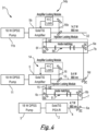
- Figure 4 presents an alternative laser system in accordance with an embodiment of the present invention, as generally depicted by reference numeral 31.
- the continuous-wave output field 12 is now employed as a seed optical field for a second optical amplifier 5b i.e. the continuous-wave output field 12 is employed as a seed optical field for the second optical amplifier 5b resulting in the second optical amplifier 5b also being slaved to the master Ti:sapphire laser 2.
- a fourth dichroic mirror 6d is employed to redirect the optical field 12 into the second optical amplifier 5b.
- a second injection locking module 7b to also be located within the optical path between the first and second slave optical amplifiers 5 and 5b to ensure that the mode of the seed optical field 12 matches that of the second optical amplifier 5b. It is also beneficial for the stable operation of the laser system 31 to frequency lock the resonance condition of the second optical amplifier 5b to the seed optical field 12, in a similar manner to that described above.
- the output field 32 of the second optical amplifier 5b is therefore combined with the output field 12 of the first optical amplifier 5b, and hence the output of the master Ti:sapphire laser 2, such that the laser system 31 provides a single output exhibiting a single transverse and longitudinal mode, single polarisation and a high phase-coherence with the first 4 and second 12 seed optical fields.
- the output field 32 has a power ⁇ 14 W which is effectively the sum of the powers of the output field 4 of the master Ti:sapphire laser 2, the output field 12 of the first optical amplifier 5 and the output field of the second optical amplifier 5b.
- the wavelength of the output field 32 is again tuneable over a 400 nm wavelength range (around 660 nm to 1060nm) as controlled by the operating wavelength of the master Ti:sapphire laser 2.
- the above described laser system 1 could in fact be scaled up by to provide an output field having a power equal to the sum of the power of the output field 4 of the master laser 2 and N additional optical amplifiers 5.
- phase locked injection-locked laser system have also been disclosed. These systems have the advantage that they provide a single output exhibiting a single transverse and longitudinal mode, a single polarisation and a high phase-coherence with the respective seed optical fields.
- An advantage of the disclosed laser systems is the fact that the output field of the injection-locked laser system is highly scalable thus providing a means for increasing the power of the generated output field.
- a further advantage of the disclosed laser system resides in the fact that the generated output field is tuneable over a 400 nm wavelength range (around 660 nm to 1060nm) as controlled by the operating wavelength of the master laser 2. This is a result of the fact that Ti;Sapphire gain media are employed within the master laser 2 and the one or more optical amplifiers 5 located in series with the master laser 2.
- Nd:YAG laser systems of the prior art are only tuneable over a range of around 0.05nm.
- the present laser system able to be employed within optical traps where it is necessary to be able to tune the laser source to different atomic wavelengths depending on the particular atom required to be trapped.
- a method and system for combining two or more optical fields is disclosed.
- a first continuous-wave high powered output field generated by a solid-state master laser is injected into a first solid state optical amplifier to produce a single output field from the laser system that exhibits a high phase-coherence with the output field of the master laser.
- the power of the output field equals the sum of powers of the master laser and that generated by the first optical amplifier, while exhibiting similar beams characteristics to that produced by the output field of the master laser i.e. it exhibits low noise, in a single transverse and longitudinal mode Gaussian beam, and has a single polarisation.
- the laser system is highly scalable in that N optical amplifiers may be located in series with the master laser to provide a single low noise, high power output field.
Landscapes
- Physics & Mathematics (AREA)
- Electromagnetism (AREA)
- Engineering & Computer Science (AREA)
- Plasma & Fusion (AREA)
- Optics & Photonics (AREA)
- Chemical & Material Sciences (AREA)
- Crystallography & Structural Chemistry (AREA)
- Inorganic Chemistry (AREA)
- Lasers (AREA)
Applications Claiming Priority (2)
| Application Number | Priority Date | Filing Date | Title |
|---|---|---|---|
| GB1810706.0A GB2575627B (en) | 2018-06-29 | 2018-06-29 | Laser System for Coherently Combining Multiple Laser Sources |
| PCT/GB2019/051831 WO2020002933A1 (en) | 2018-06-29 | 2019-06-27 | Laser system for coherently combining multiple laser sources |
Publications (3)
| Publication Number | Publication Date |
|---|---|
| EP3815201A1 EP3815201A1 (en) | 2021-05-05 |
| EP3815201C0 EP3815201C0 (en) | 2024-06-26 |
| EP3815201B1 true EP3815201B1 (en) | 2024-06-26 |
Family
ID=63143819
Family Applications (1)
| Application Number | Title | Priority Date | Filing Date |
|---|---|---|---|
| EP19745724.5A Active EP3815201B1 (en) | 2018-06-29 | 2019-06-27 | Laser system for coherently combining multiple laser sources |
Country Status (6)
| Country | Link |
|---|---|
| US (1) | US20210273398A1 (https=) |
| EP (1) | EP3815201B1 (https=) |
| JP (1) | JP7532263B2 (https=) |
| CA (1) | CA3104423A1 (https=) |
| GB (1) | GB2575627B (https=) |
| WO (1) | WO2020002933A1 (https=) |
Families Citing this family (2)
| Publication number | Priority date | Publication date | Assignee | Title |
|---|---|---|---|---|
| US12038465B2 (en) | 2022-03-11 | 2024-07-16 | The Mitre Corporation | Self-locked Rydberg atom electric field sensor |
| CN116131081B (zh) * | 2023-04-13 | 2023-07-18 | 中国人民解放军国防科技大学 | 脉冲时序激光功率放大装置及时序可控多激光系统 |
Citations (3)
| Publication number | Priority date | Publication date | Assignee | Title |
|---|---|---|---|---|
| US6483858B1 (en) * | 1999-11-23 | 2002-11-19 | Southeastern University Research Assn. | Injection mode-locking Ti-sapphire laser system |
| WO2003049239A2 (en) * | 2001-11-30 | 2003-06-12 | Positive Light, Inc. | Solid state system and method for generating ultraviolet light |
| WO2019073202A1 (en) * | 2017-10-13 | 2019-04-18 | M Squared Lasers Limited | LASER SYSTEM |
Family Cites Families (15)
| Publication number | Priority date | Publication date | Assignee | Title |
|---|---|---|---|---|
| US3646469A (en) * | 1970-03-20 | 1972-02-29 | United Aircraft Corp | Travelling wave regenerative laser amplifier |
| US3646468A (en) * | 1970-03-20 | 1972-02-29 | United Aircraft Corp | Servo aided injection phase-locked laser oscillator |
| US4649351A (en) | 1984-10-19 | 1987-03-10 | Massachusetts Institute Of Technology | Apparatus and method for coherently adding laser beams |
| US4757268A (en) | 1985-05-22 | 1988-07-12 | Hughes Aircraft Company | Energy scalable laser amplifier |
| US5027360A (en) * | 1990-06-13 | 1991-06-25 | Stanford University | High power continuous wave injection-locked solid state laser |
| US5592327A (en) * | 1994-12-16 | 1997-01-07 | Clark-Mxr, Inc. | Regenerative amplifier incorporating a spectral filter within the resonant cavity |
| JPH11317567A (ja) * | 1998-05-01 | 1999-11-16 | Sony Corp | レーザー光発生方法及びその装置 |
| JP2001230478A (ja) * | 2000-02-15 | 2001-08-24 | Mitsubishi Heavy Ind Ltd | 紫外レーザ発振器 |
| US7457326B2 (en) | 2003-01-17 | 2008-11-25 | Hrl Laboratories, Llc | Method and apparatus for coherently combining multiple laser oscillators |
| JP4945934B2 (ja) * | 2005-06-21 | 2012-06-06 | ソニー株式会社 | 光学システム、検査装置、処理装置および測定装置 |
| US7848370B2 (en) | 2007-01-26 | 2010-12-07 | Telaris Inc. | Electronically phase-locked laser systems |
| US9865986B2 (en) * | 2013-12-19 | 2018-01-09 | The Regents Of The University Of Michigan | Coherent combining pulse bursts in time domain |
| JPWO2016103483A1 (ja) * | 2014-12-26 | 2017-10-05 | 学校法人東京理科大学 | チタンサファイヤレーザ装置、及び露光装置用レーザ装置、並びにチタンサファイヤ増幅器 |
| CN107735914B (zh) * | 2015-07-14 | 2020-06-26 | 极光先进雷射株式会社 | 准分子激光装置 |
| GB2570519B (en) * | 2018-01-30 | 2022-05-11 | M Squared Lasers Ltd | Injection-locked laser system |
-
2018
- 2018-06-29 GB GB1810706.0A patent/GB2575627B/en active Active
-
2019
- 2019-06-27 WO PCT/GB2019/051831 patent/WO2020002933A1/en not_active Ceased
- 2019-06-27 JP JP2020573035A patent/JP7532263B2/ja active Active
- 2019-06-27 EP EP19745724.5A patent/EP3815201B1/en active Active
- 2019-06-27 US US17/256,057 patent/US20210273398A1/en not_active Abandoned
- 2019-06-27 CA CA3104423A patent/CA3104423A1/en active Pending
Patent Citations (3)
| Publication number | Priority date | Publication date | Assignee | Title |
|---|---|---|---|---|
| US6483858B1 (en) * | 1999-11-23 | 2002-11-19 | Southeastern University Research Assn. | Injection mode-locking Ti-sapphire laser system |
| WO2003049239A2 (en) * | 2001-11-30 | 2003-06-12 | Positive Light, Inc. | Solid state system and method for generating ultraviolet light |
| WO2019073202A1 (en) * | 2017-10-13 | 2019-04-18 | M Squared Lasers Limited | LASER SYSTEM |
Non-Patent Citations (2)
| Title |
|---|
| APPLIED PHYSICS. B, vol. 31, 1983, pages 97 - 105 * |
| OPTICS COMMUNICATION, vol. 35, no. 3, 1980, pages 441 - 444 * |
Also Published As
| Publication number | Publication date |
|---|---|
| JP2021533555A (ja) | 2021-12-02 |
| GB2575627B (en) | 2023-03-01 |
| WO2020002933A1 (en) | 2020-01-02 |
| GB2575627A (en) | 2020-01-22 |
| EP3815201C0 (en) | 2024-06-26 |
| EP3815201A1 (en) | 2021-05-05 |
| JP7532263B2 (ja) | 2024-08-13 |
| US20210273398A1 (en) | 2021-09-02 |
| CA3104423A1 (en) | 2020-01-02 |
| GB201810706D0 (en) | 2018-08-15 |
Similar Documents
| Publication | Publication Date | Title |
|---|---|---|
| US7599413B2 (en) | Self-contained module for injecting signal into slave laser without any modifications or adaptations to it | |
| US5974060A (en) | Multi-mode laser oscillator with large intermode spacing | |
| US10505335B2 (en) | Method and a system for pulsed excitation of a nonlinear medium for photon pair generation | |
| CN110854659B (zh) | 双频法拉第半导体激光器及其实现方法 | |
| JPH01222234A (ja) | 光混合によるコヒーレント光放射の生成方法及び装置 | |
| EP3815201B1 (en) | Laser system for coherently combining multiple laser sources | |
| US10418783B1 (en) | Semiconductor laser with intra-cavity electro-optic modulator | |
| US8194708B2 (en) | Laser | |
| JP2013161609A (ja) | レーザーコンプトン散乱装置 | |
| Stry et al. | Compact tunable diode laser with diffraction-limited 1 Watt for atom cooling and trapping | |
| Laurain et al. | Recent advances in power scaling of high-power optically-pumped semiconductor lasers for ultrashort pulse generation and continuous wave single frequency operation | |
| WO2020009708A1 (en) | Semiconductor laser with intra-cavity electro-optic modulator | |
| Freitag et al. | Diode-pumped solid-state lasers as light sources of Michelson-type graviational wave detectors | |
| US11962127B2 (en) | External cavity semiconductor laser | |
| Wang et al. | Wavelength tunable single-frequency Cr: ZnSe laser | |
| Amthor et al. | An injection-locked, single-mode, continuous wave Ti: Sapphire laser | |
| Hoehler et al. | High peak power GaSb-based VECSELs | |
| Priante et al. | 1178 nm Membrane External-Cavity Surface-Emitting Lasers for Sodium Guide-Star Applications | |
| Rapaport et al. | High-brightness alexandrite laser | |
| CN121461063A (zh) | 耗散克尔孤子光频梳光源激发装置 | |
| Wu et al. | Tunable pulse-burst laser system for high-speed imaging diagnostics | |
| CN120389278A (zh) | 一种窄线宽的稳频激光器 | |
| EP3132512A2 (en) | Improved passively mode-locking semiconductor disk laser (sdl) | |
| Depenheuer et al. | A pulsed laser system with large spectral coverage extended by non-linear frequency conversion | |
| WO2021095523A1 (ja) | 垂直外部共振器型面発光レーザ |
Legal Events
| Date | Code | Title | Description |
|---|---|---|---|
| STAA | Information on the status of an ep patent application or granted ep patent |
Free format text: STATUS: UNKNOWN |
|
| STAA | Information on the status of an ep patent application or granted ep patent |
Free format text: STATUS: THE INTERNATIONAL PUBLICATION HAS BEEN MADE |
|
| PUAI | Public reference made under article 153(3) epc to a published international application that has entered the european phase |
Free format text: ORIGINAL CODE: 0009012 |
|
| STAA | Information on the status of an ep patent application or granted ep patent |
Free format text: STATUS: REQUEST FOR EXAMINATION WAS MADE |
|
| 17P | Request for examination filed |
Effective date: 20210118 |
|
| AK | Designated contracting states |
Kind code of ref document: A1 Designated state(s): AL AT BE BG CH CY CZ DE DK EE ES FI FR GB GR HR HU IE IS IT LI LT LU LV MC MK MT NL NO PL PT RO RS SE SI SK SM TR |
|
| DAV | Request for validation of the european patent (deleted) | ||
| DAX | Request for extension of the european patent (deleted) | ||
| GRAP | Despatch of communication of intention to grant a patent |
Free format text: ORIGINAL CODE: EPIDOSNIGR1 |
|
| STAA | Information on the status of an ep patent application or granted ep patent |
Free format text: STATUS: GRANT OF PATENT IS INTENDED |
|
| RIC1 | Information provided on ipc code assigned before grant |
Ipc: H01S 3/08045 20230101ALN20231222BHEP Ipc: H01S 3/08031 20230101ALN20231222BHEP Ipc: H01S 3/23 20060101ALI20231222BHEP Ipc: H01S 3/10 20060101ALI20231222BHEP Ipc: H01S 3/00 20060101ALI20231222BHEP Ipc: H01S 3/0941 20060101ALI20231222BHEP Ipc: H01S 3/13 20060101ALI20231222BHEP Ipc: H01S 3/08 20060101ALI20231222BHEP Ipc: H01S 3/083 20060101ALI20231222BHEP Ipc: H01S 3/094 20060101ALI20231222BHEP Ipc: H01S 3/16 20060101AFI20231222BHEP |
|
| INTG | Intention to grant announced |
Effective date: 20240119 |
|
| GRAS | Grant fee paid |
Free format text: ORIGINAL CODE: EPIDOSNIGR3 |
|
| GRAA | (expected) grant |
Free format text: ORIGINAL CODE: 0009210 |
|
| STAA | Information on the status of an ep patent application or granted ep patent |
Free format text: STATUS: THE PATENT HAS BEEN GRANTED |
|
| AK | Designated contracting states |
Kind code of ref document: B1 Designated state(s): AL AT BE BG CH CY CZ DE DK EE ES FI FR GR HR HU IE IS IT LI LT LU LV MC MK MT NL NO PL PT RO RS SE SI SK SM TR |
|
| RBV | Designated contracting states (corrected) |
Designated state(s): AL AT BE BG CH CY CZ DE DK EE ES FI FR GR HR HU IE IS IT LI LT LU LV MC MK MT NL NO PL PT RO RS SE SI SK SM TR |
|
| REG | Reference to a national code |
Ref country code: CH Ref legal event code: EP |
|
| REG | Reference to a national code |
Ref country code: DE Ref legal event code: R096 Ref document number: 602019054218 Country of ref document: DE |
|
| U01 | Request for unitary effect filed |
Effective date: 20240722 |
|
| U07 | Unitary effect registered |
Designated state(s): AT BE BG DE DK EE FI FR IT LT LU LV MT NL PT SE SI Effective date: 20240801 |
|
| PG25 | Lapsed in a contracting state [announced via postgrant information from national office to epo] |
Ref country code: HR Free format text: LAPSE BECAUSE OF FAILURE TO SUBMIT A TRANSLATION OF THE DESCRIPTION OR TO PAY THE FEE WITHIN THE PRESCRIBED TIME-LIMIT Effective date: 20240626 |
|
| PG25 | Lapsed in a contracting state [announced via postgrant information from national office to epo] |
Ref country code: GR Free format text: LAPSE BECAUSE OF FAILURE TO SUBMIT A TRANSLATION OF THE DESCRIPTION OR TO PAY THE FEE WITHIN THE PRESCRIBED TIME-LIMIT Effective date: 20240927 |
|
| PG25 | Lapsed in a contracting state [announced via postgrant information from national office to epo] |
Ref country code: NO Free format text: LAPSE BECAUSE OF FAILURE TO SUBMIT A TRANSLATION OF THE DESCRIPTION OR TO PAY THE FEE WITHIN THE PRESCRIBED TIME-LIMIT Effective date: 20240926 Ref country code: HR Free format text: LAPSE BECAUSE OF FAILURE TO SUBMIT A TRANSLATION OF THE DESCRIPTION OR TO PAY THE FEE WITHIN THE PRESCRIBED TIME-LIMIT Effective date: 20240626 Ref country code: GR Free format text: LAPSE BECAUSE OF FAILURE TO SUBMIT A TRANSLATION OF THE DESCRIPTION OR TO PAY THE FEE WITHIN THE PRESCRIBED TIME-LIMIT Effective date: 20240927 Ref country code: RS Free format text: LAPSE BECAUSE OF FAILURE TO SUBMIT A TRANSLATION OF THE DESCRIPTION OR TO PAY THE FEE WITHIN THE PRESCRIBED TIME-LIMIT Effective date: 20240926 |
|
| PG25 | Lapsed in a contracting state [announced via postgrant information from national office to epo] |
Ref country code: PL Free format text: LAPSE BECAUSE OF FAILURE TO SUBMIT A TRANSLATION OF THE DESCRIPTION OR TO PAY THE FEE WITHIN THE PRESCRIBED TIME-LIMIT Effective date: 20240626 |
|
| PG25 | Lapsed in a contracting state [announced via postgrant information from national office to epo] |
Ref country code: IS Free format text: LAPSE BECAUSE OF FAILURE TO SUBMIT A TRANSLATION OF THE DESCRIPTION OR TO PAY THE FEE WITHIN THE PRESCRIBED TIME-LIMIT Effective date: 20241026 |
|
| PG25 | Lapsed in a contracting state [announced via postgrant information from national office to epo] |
Ref country code: CZ Free format text: LAPSE BECAUSE OF FAILURE TO SUBMIT A TRANSLATION OF THE DESCRIPTION OR TO PAY THE FEE WITHIN THE PRESCRIBED TIME-LIMIT Effective date: 20240626 |
|
| PG25 | Lapsed in a contracting state [announced via postgrant information from national office to epo] |
Ref country code: RO Free format text: LAPSE BECAUSE OF FAILURE TO SUBMIT A TRANSLATION OF THE DESCRIPTION OR TO PAY THE FEE WITHIN THE PRESCRIBED TIME-LIMIT Effective date: 20240626 Ref country code: SK Free format text: LAPSE BECAUSE OF FAILURE TO SUBMIT A TRANSLATION OF THE DESCRIPTION OR TO PAY THE FEE WITHIN THE PRESCRIBED TIME-LIMIT Effective date: 20240626 |
|
| PG25 | Lapsed in a contracting state [announced via postgrant information from national office to epo] |
Ref country code: ES Free format text: LAPSE BECAUSE OF FAILURE TO SUBMIT A TRANSLATION OF THE DESCRIPTION OR TO PAY THE FEE WITHIN THE PRESCRIBED TIME-LIMIT Effective date: 20240626 Ref country code: SM Free format text: LAPSE BECAUSE OF FAILURE TO SUBMIT A TRANSLATION OF THE DESCRIPTION OR TO PAY THE FEE WITHIN THE PRESCRIBED TIME-LIMIT Effective date: 20240626 |
|
| PG25 | Lapsed in a contracting state [announced via postgrant information from national office to epo] |
Ref country code: SM Free format text: LAPSE BECAUSE OF FAILURE TO SUBMIT A TRANSLATION OF THE DESCRIPTION OR TO PAY THE FEE WITHIN THE PRESCRIBED TIME-LIMIT Effective date: 20240626 Ref country code: SK Free format text: LAPSE BECAUSE OF FAILURE TO SUBMIT A TRANSLATION OF THE DESCRIPTION OR TO PAY THE FEE WITHIN THE PRESCRIBED TIME-LIMIT Effective date: 20240626 Ref country code: RO Free format text: LAPSE BECAUSE OF FAILURE TO SUBMIT A TRANSLATION OF THE DESCRIPTION OR TO PAY THE FEE WITHIN THE PRESCRIBED TIME-LIMIT Effective date: 20240626 Ref country code: PL Free format text: LAPSE BECAUSE OF FAILURE TO SUBMIT A TRANSLATION OF THE DESCRIPTION OR TO PAY THE FEE WITHIN THE PRESCRIBED TIME-LIMIT Effective date: 20240626 Ref country code: IS Free format text: LAPSE BECAUSE OF FAILURE TO SUBMIT A TRANSLATION OF THE DESCRIPTION OR TO PAY THE FEE WITHIN THE PRESCRIBED TIME-LIMIT Effective date: 20241026 Ref country code: ES Free format text: LAPSE BECAUSE OF FAILURE TO SUBMIT A TRANSLATION OF THE DESCRIPTION OR TO PAY THE FEE WITHIN THE PRESCRIBED TIME-LIMIT Effective date: 20240626 Ref country code: CZ Free format text: LAPSE BECAUSE OF FAILURE TO SUBMIT A TRANSLATION OF THE DESCRIPTION OR TO PAY THE FEE WITHIN THE PRESCRIBED TIME-LIMIT Effective date: 20240626 |
|
| REG | Reference to a national code |
Ref country code: CH Ref legal event code: PL |
|
| U21 | Renewal fee for the european patent with unitary effect paid with additional fee |
Year of fee payment: 6 Effective date: 20250128 |
|
| PG25 | Lapsed in a contracting state [announced via postgrant information from national office to epo] |
Ref country code: MC Free format text: LAPSE BECAUSE OF FAILURE TO SUBMIT A TRANSLATION OF THE DESCRIPTION OR TO PAY THE FEE WITHIN THE PRESCRIBED TIME-LIMIT Effective date: 20240626 |
|
| PG25 | Lapsed in a contracting state [announced via postgrant information from national office to epo] |
Ref country code: MC Free format text: LAPSE BECAUSE OF FAILURE TO SUBMIT A TRANSLATION OF THE DESCRIPTION OR TO PAY THE FEE WITHIN THE PRESCRIBED TIME-LIMIT Effective date: 20240626 |
|
| PG25 | Lapsed in a contracting state [announced via postgrant information from national office to epo] |
Ref country code: IE Free format text: LAPSE BECAUSE OF NON-PAYMENT OF DUE FEES Effective date: 20240627 |
|
| PG25 | Lapsed in a contracting state [announced via postgrant information from national office to epo] |
Ref country code: CH Free format text: LAPSE BECAUSE OF NON-PAYMENT OF DUE FEES Effective date: 20240630 |
|
| PLBE | No opposition filed within time limit |
Free format text: ORIGINAL CODE: 0009261 |
|
| STAA | Information on the status of an ep patent application or granted ep patent |
Free format text: STATUS: NO OPPOSITION FILED WITHIN TIME LIMIT |
|
| 26N | No opposition filed |
Effective date: 20250327 |
|
| PG25 | Lapsed in a contracting state [announced via postgrant information from national office to epo] |
Ref country code: CY Free format text: LAPSE BECAUSE OF FAILURE TO SUBMIT A TRANSLATION OF THE DESCRIPTION OR TO PAY THE FEE WITHIN THE PRESCRIBED TIME-LIMIT; INVALID AB INITIO Effective date: 20190627 |
|
| U21 | Renewal fee for the european patent with unitary effect paid with additional fee |
Year of fee payment: 7 Effective date: 20251222 |
|
| PG25 | Lapsed in a contracting state [announced via postgrant information from national office to epo] |
Ref country code: HU Free format text: LAPSE BECAUSE OF FAILURE TO SUBMIT A TRANSLATION OF THE DESCRIPTION OR TO PAY THE FEE WITHIN THE PRESCRIBED TIME-LIMIT; INVALID AB INITIO Effective date: 20190627 |