EP3813633B1 - Endoscope - Google Patents
Endoscope Download PDFInfo
- Publication number
- EP3813633B1 EP3813633B1 EP19825639.8A EP19825639A EP3813633B1 EP 3813633 B1 EP3813633 B1 EP 3813633B1 EP 19825639 A EP19825639 A EP 19825639A EP 3813633 B1 EP3813633 B1 EP 3813633B1
- Authority
- EP
- European Patent Office
- Prior art keywords
- shaft
- endoscope
- channel
- handle
- distal
- Prior art date
- Legal status (The legal status is an assumption and is not a legal conclusion. Google has not performed a legal analysis and makes no representation as to the accuracy of the status listed.)
- Active
Links
Images


Classifications
-
- A—HUMAN NECESSITIES
- A61—MEDICAL OR VETERINARY SCIENCE; HYGIENE
- A61B—DIAGNOSIS; SURGERY; IDENTIFICATION
- A61B1/00—Instruments for performing medical examinations of the interior of cavities or tubes of the body by visual or photographical inspection, e.g. endoscopes; Illuminating arrangements therefor
- A61B1/012—Instruments for performing medical examinations of the interior of cavities or tubes of the body by visual or photographical inspection, e.g. endoscopes; Illuminating arrangements therefor characterised by internal passages or accessories therefor
- A61B1/018—Instruments for performing medical examinations of the interior of cavities or tubes of the body by visual or photographical inspection, e.g. endoscopes; Illuminating arrangements therefor characterised by internal passages or accessories therefor for receiving instruments
-
- A—HUMAN NECESSITIES
- A61—MEDICAL OR VETERINARY SCIENCE; HYGIENE
- A61B—DIAGNOSIS; SURGERY; IDENTIFICATION
- A61B1/00—Instruments for performing medical examinations of the interior of cavities or tubes of the body by visual or photographical inspection, e.g. endoscopes; Illuminating arrangements therefor
- A61B1/00002—Operational features of endoscopes
- A61B1/00011—Operational features of endoscopes characterised by signal transmission
- A61B1/00018—Operational features of endoscopes characterised by signal transmission using electrical cables
-
- A—HUMAN NECESSITIES
- A61—MEDICAL OR VETERINARY SCIENCE; HYGIENE
- A61B—DIAGNOSIS; SURGERY; IDENTIFICATION
- A61B1/00—Instruments for performing medical examinations of the interior of cavities or tubes of the body by visual or photographical inspection, e.g. endoscopes; Illuminating arrangements therefor
- A61B1/00002—Operational features of endoscopes
- A61B1/00039—Operational features of endoscopes provided with input arrangements for the user
- A61B1/00042—Operational features of endoscopes provided with input arrangements for the user for mechanical operation
-
- A—HUMAN NECESSITIES
- A61—MEDICAL OR VETERINARY SCIENCE; HYGIENE
- A61B—DIAGNOSIS; SURGERY; IDENTIFICATION
- A61B1/00—Instruments for performing medical examinations of the interior of cavities or tubes of the body by visual or photographical inspection, e.g. endoscopes; Illuminating arrangements therefor
- A61B1/00064—Constructional details of the endoscope body
- A61B1/00066—Proximal part of endoscope body, e.g. handles
-
- A—HUMAN NECESSITIES
- A61—MEDICAL OR VETERINARY SCIENCE; HYGIENE
- A61B—DIAGNOSIS; SURGERY; IDENTIFICATION
- A61B1/00—Instruments for performing medical examinations of the interior of cavities or tubes of the body by visual or photographical inspection, e.g. endoscopes; Illuminating arrangements therefor
- A61B1/00064—Constructional details of the endoscope body
- A61B1/00071—Insertion part of the endoscope body
- A61B1/0008—Insertion part of the endoscope body characterised by distal tip features
- A61B1/00094—Suction openings
-
- A—HUMAN NECESSITIES
- A61—MEDICAL OR VETERINARY SCIENCE; HYGIENE
- A61B—DIAGNOSIS; SURGERY; IDENTIFICATION
- A61B1/00—Instruments for performing medical examinations of the interior of cavities or tubes of the body by visual or photographical inspection, e.g. endoscopes; Illuminating arrangements therefor
- A61B1/00112—Connection or coupling means
- A61B1/00114—Electrical cables in or with an endoscope
-
- A—HUMAN NECESSITIES
- A61—MEDICAL OR VETERINARY SCIENCE; HYGIENE
- A61B—DIAGNOSIS; SURGERY; IDENTIFICATION
- A61B1/00—Instruments for performing medical examinations of the interior of cavities or tubes of the body by visual or photographical inspection, e.g. endoscopes; Illuminating arrangements therefor
- A61B1/00112—Connection or coupling means
- A61B1/00121—Connectors, fasteners and adapters, e.g. on the endoscope handle
- A61B1/00124—Connectors, fasteners and adapters, e.g. on the endoscope handle electrical, e.g. electrical plug-and-socket connection
-
- A—HUMAN NECESSITIES
- A61—MEDICAL OR VETERINARY SCIENCE; HYGIENE
- A61B—DIAGNOSIS; SURGERY; IDENTIFICATION
- A61B1/00—Instruments for performing medical examinations of the interior of cavities or tubes of the body by visual or photographical inspection, e.g. endoscopes; Illuminating arrangements therefor
- A61B1/005—Flexible endoscopes
- A61B1/0051—Flexible endoscopes with controlled bending of insertion part
- A61B1/0052—Constructional details of control elements, e.g. handles
-
- A—HUMAN NECESSITIES
- A61—MEDICAL OR VETERINARY SCIENCE; HYGIENE
- A61B—DIAGNOSIS; SURGERY; IDENTIFICATION
- A61B1/00—Instruments for performing medical examinations of the interior of cavities or tubes of the body by visual or photographical inspection, e.g. endoscopes; Illuminating arrangements therefor
- A61B1/012—Instruments for performing medical examinations of the interior of cavities or tubes of the body by visual or photographical inspection, e.g. endoscopes; Illuminating arrangements therefor characterised by internal passages or accessories therefor
- A61B1/015—Control of fluid supply or evacuation
-
- A—HUMAN NECESSITIES
- A61—MEDICAL OR VETERINARY SCIENCE; HYGIENE
- A61B—DIAGNOSIS; SURGERY; IDENTIFICATION
- A61B1/00—Instruments for performing medical examinations of the interior of cavities or tubes of the body by visual or photographical inspection, e.g. endoscopes; Illuminating arrangements therefor
- A61B1/04—Instruments for performing medical examinations of the interior of cavities or tubes of the body by visual or photographical inspection, e.g. endoscopes; Illuminating arrangements therefor combined with photographic or television appliances
- A61B1/05—Instruments for performing medical examinations of the interior of cavities or tubes of the body by visual or photographical inspection, e.g. endoscopes; Illuminating arrangements therefor combined with photographic or television appliances characterised by the image sensor, e.g. camera, being in the distal end portion
-
- A—HUMAN NECESSITIES
- A61—MEDICAL OR VETERINARY SCIENCE; HYGIENE
- A61B—DIAGNOSIS; SURGERY; IDENTIFICATION
- A61B1/00—Instruments for performing medical examinations of the interior of cavities or tubes of the body by visual or photographical inspection, e.g. endoscopes; Illuminating arrangements therefor
- A61B1/303—Instruments for performing medical examinations of the interior of cavities or tubes of the body by visual or photographical inspection, e.g. endoscopes; Illuminating arrangements therefor for the vagina, i.e. vaginoscopes
-
- A—HUMAN NECESSITIES
- A61—MEDICAL OR VETERINARY SCIENCE; HYGIENE
- A61B—DIAGNOSIS; SURGERY; IDENTIFICATION
- A61B1/00—Instruments for performing medical examinations of the interior of cavities or tubes of the body by visual or photographical inspection, e.g. endoscopes; Illuminating arrangements therefor
- A61B1/00002—Operational features of endoscopes
- A61B1/00043—Operational features of endoscopes provided with output arrangements
- A61B1/00045—Display arrangement
- A61B1/00052—Display arrangement positioned at proximal end of the endoscope body
-
- A—HUMAN NECESSITIES
- A61—MEDICAL OR VETERINARY SCIENCE; HYGIENE
- A61B—DIAGNOSIS; SURGERY; IDENTIFICATION
- A61B1/00—Instruments for performing medical examinations of the interior of cavities or tubes of the body by visual or photographical inspection, e.g. endoscopes; Illuminating arrangements therefor
- A61B1/00064—Constructional details of the endoscope body
- A61B1/00105—Constructional details of the endoscope body characterised by modular construction
-
- A—HUMAN NECESSITIES
- A61—MEDICAL OR VETERINARY SCIENCE; HYGIENE
- A61B—DIAGNOSIS; SURGERY; IDENTIFICATION
- A61B1/00—Instruments for performing medical examinations of the interior of cavities or tubes of the body by visual or photographical inspection, e.g. endoscopes; Illuminating arrangements therefor
- A61B1/00131—Accessories for endoscopes
- A61B1/00135—Oversleeves mounted on the endoscope prior to insertion
-
- A—HUMAN NECESSITIES
- A61—MEDICAL OR VETERINARY SCIENCE; HYGIENE
- A61B—DIAGNOSIS; SURGERY; IDENTIFICATION
- A61B1/00—Instruments for performing medical examinations of the interior of cavities or tubes of the body by visual or photographical inspection, e.g. endoscopes; Illuminating arrangements therefor
- A61B1/00163—Optical arrangements
- A61B1/00174—Optical arrangements characterised by the viewing angles
-
- A—HUMAN NECESSITIES
- A61—MEDICAL OR VETERINARY SCIENCE; HYGIENE
- A61B—DIAGNOSIS; SURGERY; IDENTIFICATION
- A61B1/00—Instruments for performing medical examinations of the interior of cavities or tubes of the body by visual or photographical inspection, e.g. endoscopes; Illuminating arrangements therefor
- A61B1/06—Instruments for performing medical examinations of the interior of cavities or tubes of the body by visual or photographical inspection, e.g. endoscopes; Illuminating arrangements therefor with illuminating arrangements
- A61B1/0661—Endoscope light sources
- A61B1/0676—Endoscope light sources at distal tip of an endoscope
-
- A—HUMAN NECESSITIES
- A61—MEDICAL OR VETERINARY SCIENCE; HYGIENE
- A61B—DIAGNOSIS; SURGERY; IDENTIFICATION
- A61B1/00—Instruments for performing medical examinations of the interior of cavities or tubes of the body by visual or photographical inspection, e.g. endoscopes; Illuminating arrangements therefor
- A61B1/06—Instruments for performing medical examinations of the interior of cavities or tubes of the body by visual or photographical inspection, e.g. endoscopes; Illuminating arrangements therefor with illuminating arrangements
- A61B1/0661—Endoscope light sources
- A61B1/0684—Endoscope light sources using light emitting diodes [LED]
-
- A—HUMAN NECESSITIES
- A61—MEDICAL OR VETERINARY SCIENCE; HYGIENE
- A61B—DIAGNOSIS; SURGERY; IDENTIFICATION
- A61B1/00—Instruments for performing medical examinations of the interior of cavities or tubes of the body by visual or photographical inspection, e.g. endoscopes; Illuminating arrangements therefor
- A61B1/307—Instruments for performing medical examinations of the interior of cavities or tubes of the body by visual or photographical inspection, e.g. endoscopes; Illuminating arrangements therefor for the urinary organs, e.g. urethroscopes, cystoscopes
Definitions
- the present invention relates generally to medical devices. More particularly, the present invention is related to endoscopes suitable for hysterectomy and other purposes.
- Endoscopic systems of the invention intended for hysterectomy typically comprise a base station having an image display, a disposable endoscope component with an image sensor, a re-usable handle component that is connected to an image processor in base station, and a fluid management system integrated with the base station and handle component.
- the endoscope component and the re-useable handle are typically referred to as a hysteroscope.
- hysteroscopes and other endoscopes provide for the introduction of interventional tools through a working channel in the shaft of the scope.
- the size of the working channel of a hysteroscope is limited by the need to introduce at least a distal portion of the shaft through the patient's cervix.
- hysteroscopes may have a shaft rotatable relative to the handle, and that shaft will often carry a camera and light source that need to be externally connected through the handle.
- US 2017/0319047 describes a hysteroscopy device with an image capturing structure located at a distal end of an elongated member and communicating video signals with a monitor.
- the hysteroscopic device comprises a rotatable shaft and slack compensation for the electrical leads between the image capturing structure and a proximal connector in the handle.
- the elongated member and the image capturing structure are dimensioned for insertion into the patient's uterus through the cervix.
- US 2018/160893 describes an endoscope having a shaft extending along a longitudinal axis to a distal housing. An image sensor is carried by the distal housing and a channel extends through the shaft and distal housing.
- a distal portion of the channel is adjustable or curved to accommodate the introduction of a tool while maintaining a reduced shaft diameter.
- a diagonal dimension of the image sensor when combined with the channel diameter is greater than a shaft diameter.
- the distal housing may be flexible to accommodate passage of a straight tool through a curved distal portion of a working channel.
- a hysteroscope or other endoscopic system comprises a shaft having an outer shaft diameter, a distal shaft portion, a proximal shaft portion, and a longitudinal axis there between.
- a handle is coupled to the proximal portion of the shaft, and an image sensor with a diagonal dimension is carried by the distal portion of the shaft.
- a channel extends through at least the distal shaft portion and has a channel diameter.
- a section of the channel in the distal portion of the shaft is re-configurable between a constricted shape or geometry and a non-constricted shape or geometry to accommodate a tool introduced there through.
- the combined diagonal dimension and channel diameter may be greater than the outer shaft diameter.
- the handle will typically be detachably coupled to the shaft so that the handle is reusable and the shaft is disposable, but at least some aspects of the present disclosure will be found in endoscopes comprising fixed handle-shaft structures as well.
- the diagonal dimension will be at least 50% of the outer shaft diameter, typically being at least 60%, or greater.
- the channel diameter will also be at least 50% of the outer shaft diameter, more often being at least 60% of the outer shaft diameter, or greater.
- the endoscopes of the present disclosure will be provided in systems which further comprise a fluid inflow source for providing fluid flow through an inflow channel in the shaft to an outlet in the distal portion of the shaft.
- a fluid inflow source for providing fluid flow through an inflow channel in the shaft to an outlet in the distal portion of the shaft.
- such systems will further comprise a negative pressure source for providing fluid outflows through the outflow channel in the shaft and an opening in the distal shaft portion.
- the systems may comprises a controller for controlling fluid flows through the inflow and outflow channels and at least one actuator in the handle for adjusting fluid inflows and outflows.
- the controller may be configured with algorithms for operating the fluid inflow source and the negative pressure source to maintain fluid within a set pressure range in a working space, such as the uterine cavity.
- a hysteroscope or other endoscope comprises a handle having an interior, an axis, and an electrical connector fixed to the handle.
- a shaft is removably or otherwise coupled to the handle and configured to rotate, typically reversibly rotate, about a longitudinal axis relative to the handle through an arc of about 180° or greater.
- An electronic image sensor is carried at a distal end of the shaft, and one or more electrical leads extend from the image sensor to the electrical connector in the handle.
- the electrical lead(s) are flexible and configured with a "slack" portion in the interior of the handle to accommodate rotation of the shaft.
- slack it is meant that the length of the electrical lead(s) is greater than the distance between the electrical connector and the point of attachment of the electrical lead(s) to the shaft so that the shaft may be rotated without over tensioning the electrical lead(s).
- the slack portion may be formed as any one of a coil, a spiral, a folded structure, a serpentine structure, or the like.
- one end of the slack portion will be coupled to and extend around the axis of the rotating shaft assembly, typically being carried on a spool secured to the shaft assembly.
- the spool is usually aligned concentric or co-axially with the axis of the shaft so that as the shaft is rotated, the spool may take up or let out the flexible electrical leads as needed.
- the electrical leads may comprise the flex circuits.
- a light emitter may be carried at the distal end of the shaft and second electrical lead(s) may extend from the light emitter to a second electrical connector fixed in the handle.
- the second electrical leads are configured with a second slack portion to accommodate rotation of the shaft.
- the second shaft portion may also be carried on a second spool and may comprise a flex circuit.
- a channel may be formed in the shaft where a portion of the channel is re-configurable between a constricted shape and a non-constricted shape to accommodate introduction to a tool through the channel.
- the combined diagonal dimension and channel diameter will typically be greater than an outer shaft diameter.
- Other specific aspects of the re-configurable channel described above with respect to the earlier embodiment may also be found in the endoscopes of the second aspect herein.
- an endoscope comprises a handle and an elongated shaft.
- the elongated shaft is mounted to rotate, typically reversibly, at least 180° about a longitudinal axis of the handle.
- An electronic image sensor is carried near a distal end of the shaft, and electrical leads extend from the image sensor to the handle.
- the electrical leads are configured to coil and uncoil (spool and unspool) over the shaft as the shaft is rotated in opposite directions about the longitudinal axis.
- the electrical leads may comprise a flex circuit and at least a portion of the flex circuit may have a cross-sectional area that is less than 5% of the cross-sectional area of the shaft assembly.
- an endoscope comprises a handle in a elongated shaft mounted to rotate by at least 180° about a longitudinal axis of the handle.
- a flow channel extends though the shaft assembly to a port in a distal end of the shaft.
- the flow channel has a proximal channel portion fixed in the handle and a distal channel portion that rotates together with the shaft.
- a fluid-tight housing intermediate the proximal and distal channel portions is configured to provide a fluid-tight path through the channel portions within the full rotational range of the shaft.
- the rotating shaft may include an annular flow channel that rotates in the housing.
- the endoscope may still further include a second flow channel extending through the handle and shaft assembly, where the second flow channel has a proximal channel portion fixed in the handle component and a distal channel portion that rotates in the shaft as the flow channel rotates in the housing.
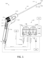
- FIG. 1 illustrates a hysteroscopic treatment system 50 which comprises multiple components including an endoscopic viewing system 100 and a fluid management system 105 housed in a base unit or console 108.
- the base unit 108 also carries a controller 110A and power source for operating the system 50 and can include an image processor 110B for processing signals from an image sensor carried by the endoscopic viewing system.
- a display 112 can be coupled to the base unit 108 for viewing images provided by the endoscopic viewing system 100.
- the endoscopic viewing system 100 of FIGS. 1 and 2 includes a re-usable handle component 120 with a finger-actuated control pad 122 and a disposable single-use endoscope component 125 with an elongated endoscope shaft 126 that carries a distal electronic imaging sensor 128 (see FIGS. 1 and 7A ).
- the fluid management system 105 includes a first peristaltic inflow pump 140A and second peristaltic outflow pump 140B, a fluid source 142 and fluid collection reservoir 144 which can include a fluid deficit measurement subsystem as is known in the art. Each of the systems and subsystems will be described in more detail below.
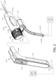
- the endoscopic viewing system 100 includes a handle component 120 and a detachable single-use endoscope component 125.
- the single-use endoscope component 125 can be seen as an assembly of a proximal handle housing 145 which carries a rotating shaft assembly 150 that is configured to rotate the handle housing 145.
- the rotating shaft assembly 150 includes a proximal cylindrical grip 152 that is coupled to a molded rotating core 155 that in turn is coupled to elongated outer sleeve 160 that extends to the distal working end 162 the endoscope component 125 ( FIG. 1 ).
- the rotating shaft assembly 150 rotates around a rotational axis 165.
- a working channel 170 extends about axis 165 through the rotating shaft assembly 150 from a proximal port 172 (see FIGS. 2 and 6 ).
- the working channel sleeve 174 that carries the working channel 170 can be seen in FIGS. 3A , 3B and 5 .
- the shaft assembly 150 rotates about the central longitudinal axis 165 of the working channel 170.
- the outer sleeve 160 has a central longitudinal axis 175 that is offset from the longitudinal axis 165 around which the shaft assembly 150 rotates.
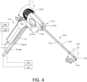
- FIG. 4 shows that the grip 152 has a visual marker 178 that is aligned with the offset distal tip section 185 to allow the operator to know the orientation of the image sensor 128 by observation of the grip 152.
- the endoscope shaft 126 and more particularly the outer sleeve 160 extends in a straight proximal sleeve portion 180 to an offset distal tip section 185 with an axis 182 that is also from 2 to 10 mm offset from the central axis 175 of the outer sleeve 160 ( FIG. 7A ).
- the outer sleeve 160 has a transition section 186 that extends at an angle ranging between 10° and 45° over a length of 5 to 20 mm between the straight proximal sleeve section 180 and the offset distal tip section 185.
- the imaging sensor 128 is disposed at the distal end of the offset tip section 185 (see FIG. 7A ).
- the endoscope component 125 and more in particular the working channel 170 is adapted to receive an elongate tool 188 that can be introduced through the working channel 170.
- the elongated outer sleeve 160 in each of the straight, transition and distal tip sections (180, 186 and 185, respectively) has a diameter ranging between 4 mm and 10 mm with an overall length configured for use in hysteroscopy. More commonly, the diameter of endoscope shaft 126 is from 5 mm to 6 mm in diameter.
- the endoscope shaft 126 with the angled transition section 186 and offset distal tip section185 can be introduced through a patient's cervical canal without dilation beyond the dilation necessary for the profile or diameter SD of the straight proximal sleeve section 180.
- the tissue around the patient's cervical canal conforms to the angles in the endoscope shaft 126 as the shaft is being advanced through the cervical canal.
- the handle housing 145 of endoscope component 125 is adapted for sliding, detachable engagement with the handle component 120 as can be best seen in FIGS. 2 and 4 .
- the operator can grip the pistol grip handle component 120 with one hand and rotate the cylindrical rotating grip 152 with the fingers of the other hand to rotate the endoscope shaft and image sensor 128 to orient the viewing angle of the image sensor 128 and a tool 188 to any desired rotational angle.
- the rotating shaft assembly 150 can be rotated at least 180° and more often at least 270° ( FIGS. 3B and 5 ). In one variation, the shaft assembly 150 can be rotated 360° so as to orient the image sensor 128 in any superior, lateral or downward direction relative to the handle housing 145.
- the handle housing 145 carries a projecting electrical connector 190A that is adapted to couple to a mating electrical connector 190B in the handle component 120.
- FIG. 2 illustrates that the endoscope component 125 is configured for axial sliding engagement with the handle component 120, it should be appreciated that the angled pistol grip portion 192 of the handle component 120 could plug into the endoscope component 125 in a different arrangement, such as a male-female plug connector or a threaded connector aligned with the axis 194 of the angled grip portion 192.
- the endoscope component 125 comprises a sterile device for use in the sterile field, while the handle component 120 may not be sterilized and is typically adapted for use for use in a non-sterile field.
- a cable 195 extends from the handle component 120 to the base unit 108, imaging processor 110B and controller 110A which includes a power source (see FIG. 1 ).
- the endoscope component 125 includes fluid inflow tubing 200A and fluid outflow tubing 200B that communicate with the fluid management system 105 which is shown schematically in FIG. 1 .
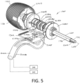
- the endoscope handle housing 145 can consist of two injection molded plastic shell elements, 204a and 204b (see FIG. 4 ), and FIG. 3A shows one shell element 204a removed to show the interior of the handle housing 145. It can be seen that both the inflow tubing 200A and outflow tubing 200B are coupled to an injection molded flow channel housing 205 with an interior bore 208 that is configured to receive a rotating core 155 of the rotating shaft assembly 150.
- FIG. 3B is another view similar to that of FIG. 3A with the second shell element 204b removed and the flow channel housing 205 also removed (phantom view) to illustrate how the stationary inflow and outflow tubing, 200A and 200B, communicate with the inflow and outflow pathways in the rotating shaft assembly 150 which rotates at least 180°.
- the rotating core 155 is centrally aligned with the axis 165 of working channel 170 and is further coupled to the off-center elongated outer sleeve 160 of the endoscope shaft 126.
- the proximal end 212 of the rotating core 155 is fixed to the grip 152 for rotating the rotating core 155 in the flow channel housing 205.
- the rotating core 155 includes first, second and third flanges 218a, 218b and 218c which define annular flow channels 220 and 222 therebetween. It can be seen that annular channel 220 is disposed between the first and second flanges 218a and 218b. Annular channel 222 is disposed between the second and third flanges 218b and 218c. Each of the first, second and third flanges 218a, 218b and 218c carry an outer O-ring 224a, 224b and 224c. From the views of FIGS.
- each of the annular flow channels 222 and 220 can rotate up to 360° and communicate with the stationary distal ends of the inflow tubing 200A and outflow tubing 200B.
- FIG. 3B further shows how the annular flow channels 222 in 220 communicate with separate flow pathways that extend through the interior of the elongated sleeve 160 to the working end 162 of the endoscope shaft 126.
- the fluid inflow pathway can be seen in FIG. 3B which extends through annular gaps AG around the exterior of inner sleeve portion 235 of the rotating core 155 within the second annular channel 222.
- Such annular gaps AG extend distally to communicate with the interior bore 242 of the outer sleeve 160.
- the pathway within said interior bore 242 transitions to the inflow sleeve 244 with distal outlet 245 as shown in FIGS. 7A-7B .
- the fluid outflow pathway also can be seen in FIG. 3B wherein an opening 250 is provided in the inner surface of annular space 220 of the rotating core 155 which communicates with the interior working channel 170.
- the outflow pathway from a working space in one variation comprises the working channel 170 which is fully open for fluid outflows when there is no tool 188 in the working channel.
- a tool seal 252 is shown in the proximal region of the working channel 170 that seals the channel 170 and also permits the tool 188 to be introduced therethrough.
- Many types of seals are known such in the art as silicone sleeve seals, flap seals and the like.
- the working channel 170 as outflow passageway is adapted for diagnostic procedures when using the endoscope without a tool in the working channel.
- the endoscope shaft 126 can be navigated through a patient's end cervical canal with the inflow and outflow pumps 140A and 140B (see FIG. 1 ) operating to provide continuous irrigation through the distal tip section 185 of the endoscope component 125 together with endoscopic viewing by means of image sensor 128.
- the inflow and outflow pumps 140A and 140B see FIG. 1
- Such a variation will thus allow fluid inflows through annular channel 222 and fluid outflows through the working channel 170 and annular channel 220.
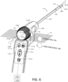
- the endoscope shaft 126 has a small insertion profile or configuration that consists of the outer diameter of the elongated outer sleeve 160 which includes the proximal straight section 180, the angled transition section 186 and the distal tip section 185 ( FIG. 7A ). It can be seen in FIG. 7A that the distal tip section 185 carries carries an image sensor 128 and two LEDs 260 which require an electrical connection to base unit 108, the controller 110A and imaging processor 110B.
- FIG. 7A shows the flex circuit ribbon 265 extending from the image sensor 128 proximally within outer sleeve 160. In one variation shown in FIGS.
- a second flex circuit ribbon 270 is provided to power the LEDs 260.
- the first flex circuit ribbon 265 could potentially carry electrical leads to the image sensor 128 and to the two LEDs 260.
- the rotating shaft assembly 150 includes a first or distal spool 280 around which the flex circuit ribbon 265 can be coiled or spooled.
- the distal spool 280 is formed as a part of the rotating core 155 of the rotating shaft assembly 150.
- Any suitable length of the flex circuit ribbon 265 can be provided as needed to allow for at least 180° rotation, or more often, 360° of rotation of the rotating shaft assembly 150 relative to the handle housing 145.
- a second or proximal spool 285 comprises a portion of the rotating core 155 and is adapted for receiving a slack length of the second flex circuit ribbon 270 that extends to the two LEDs 260.
- the proximal ends 265', 270' of the flex circuit ribbons 265, 270 are coupled to electrical connector 190A by plug connector 288a and 288b. While the variation of FIGS.
- 3A-3B shows the endoscope handle accommodating the flex circuit ribbon 265 in a spool 280, it should be appreciated that the slack portion of the flex circuit ribbon can be configured with at least one of a coiled form, spiral form or folded form without a spool.
- electrical leads extending to the image sensor 128 are in a cable or ribbon that has a cross-section that is less than 5% or the cross-section of the endoscope shaft 126.
- the endoscope comprises a shaft carrying a distal image sensor, a working channel extending through the shaft wherein the working channel in a distal shaft portion is re-configurable between a constricted shape and a non-constricted shape to accommodate a tool introduced therethrough, wherein the combined diagonal dimension DD of the sensor and the diameter WCD of the working channel 170 is greater than the shaft diameter SD in its insertion configuration or profile (see FIGS. 4 , 6 and 7A ).
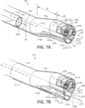
- FIG. 7B next shows the distal working channel portion 170' in its second expanded configuration as when a physician inserts an elongated tool 188 (phantom view) through the working channel 170.
- a tool 188 will initially slide along the hinge portion 298 of the lower sleeve portion 296 and then stretch the elastomeric sleeve 310 to open distal working channel portion 170' to allow the tool 188 to extend through the working channel.
- the elastomeric sleeve 310 will be stretched or deformed to a tensioned position as shown in FIG. 7B as a tool is inserted through the distal working channel portion 170'.
- the elastomeric sleeve 310 When the tool 188 is withdrawn from the working channel portion 170', the elastomeric sleeve 310 will return from the tensioned position of FIG. 7B to the repose or non-tensioned position of FIG. 7A to return the working channel portion 170' to the constricted configuration FIG. 7A .
- the endoscope component 125 corresponding to the disclosure allows for the use of an image sensor 128 having a large diagonal dimension relative to the insertion profile or diameter of the endoscope shaft 126 while at the same time providing a working channel 170 that has a large working channel diameter WCD relative to the insertion profile or diameter of the endoscope shaft assembly 126.
- the endoscope component 125 comprises endoscope shaft 126 having a shaft diameter SD extending to a distal sleeve section 185, an image sensor 128 with a diagonal dimension DD carried by the distal sleeve section 185 and a working channel 170 having a diameter WCD extending through the elongated shaft 126, wherein the working channel portion 170' in the distal end of the shaft 126 is adjustable in shape to accommodate a tool 188 introduced therethrough and wherein the combination or the sensor's diagonal dimension DD and the working channel diameter WCD is greater than the shaft diameter SD (see FIG. 7A ).
- the sensor diagonal dimension DD is greater than 50% of the shaft diameter SD or greater than 60% of the shaft diameter.
- the working channel diameter WCD is greater than 30% of the shaft diameter, greater than 40% of the shaft diameter or greater than 50% of the shaft diameter.
- the working channel portion 170' in the distal end is adjustable between a first cross-sectional dimension and a second cross-section dimension.
- the working channel portion 170' in the distal region of the endoscope shaft 126 is adjustable between a partially constricted shapes and a non-constricted shape.
- the distal tip section 185 of the endoscope shaft 126 has an axial dimension D1 ranging from 5 mm to 20 mm.
- the angled transition sleeve section 186 extends over a similar axial dimension D2 ranging from 5 mm to 20 mm.
- the central axis 182 of distal tip section 185 can be parallel to and offset from the longitudinal axis 175 of the straight shaft section 180 by a distance ranging from 1 mm to 10 mm.
- the image sensor 128 is carried in a sensor housing 340 that also carries a lens assembly 345 as is known in the art.
- the housing 340 also carries one or more light emitters, in the variation shown in FIGS. 7A and 7B , two LEDs indicated at 260 are shown carried in opposing sides of the sensor housing 340.
- the distalmost surface 350 of the lens assembly 345 and the LEDs 260 are disposed distally outward from the distal surface 352 of distal tip section 185 as shown in FIG. 8 .
- the distance indicated at D3 in FIG. 7 can range from 0.2 mm to 2.0 mm.
- FIG. 7A another aspect of the disclosure comprises an optional dedicated fluid pressure sensing channel 360 that extends through a thin wall sleeve (not shown) in the endoscope shaft 126.
- the distal end of the pressure sensing channel 360 is open in the distal surface 352 of the endoscope shaft 126.
- the pressure sensing channel 360 can extend to disposable pressure sensor in the handle housing 145 (not shown) Such a disposable pressure sensor then can have electrical leads coupled through the electrical connector 190A in the handle housing 145 thereby send electrical signals indicating pressure to the controller 110A ( FIG. 1 ).
- the disposable endoscope component 125 carries a single-use pressure sensor coupled by a detachable connector to a remote controller 110A.
- the wall of the pressure sensing channel 360 consist of a hydrophobic material, which can be any suitable polymer such as PFTE, having an interior diameter ranging from 0.25 mm to 2.5 mm. Often, the diameter of channel 360 is between 0.5 mm and 1.5 mm. It has been found that a hydrophobic surface in a pressure sensing channel 360 will prevent the migration of fluid into the channel and thereby trap an air column in the channel communicating with the pressure sensor. The compressibility of the air column in the pressure sensing channel 360 is not significantly affect the sensed pressure since the channel diameter is very small.
- a metal sleeve can be coated with a hydrophobic surface or an ultrahydrophobic surface.
- the handle component 120 has an angled pistol grip portion 192 with an axis 194 that is angled from 10° to 90° away from the axis 175 of the endoscope shaft 126.
- the grip portion 192 includes a finger or thumb-actuated control pad 122 that carries actuator buttons for operating all the functions of the treatment system, for parallel to and offset from the longitudinal axis 175 of the straight shaft section 180 by a distance ranging from 1 mm to 10 mm.
- the image sensor 128 is carried in a sensor housing 340 that also carries a lens assembly 345 as is known in the art.
- the housing 340 also carries one or more light emitters, in the variation shown in FIGS. 7A and 7B , two LEDs indicated at 260 are shown carried in opposing sides of the sensor housing 340.
- the distalmost surface 350 of the lens assembly 345 and the LEDs 260 are disposed distally outward from the distal surface 352 of distal tip section 185 as shown in FIG. 8 .
- the distance indicated at D3 in FIG. 7 can range from 0.2 mm to 2.0 mm.
- FIG. 7A another aspect of the invention comprises an optional dedicated fluid pressure sensing channel 360 that extends through a thin wall sleeve (not shown) in the endoscope shaft 126.
- the distal end of the pressure sensing channel 360 is open in the distal surface 352 of the endoscope shaft 126.
- the pressure sensing channel 360 can extend to disposable pressure sensor in the handle housing 145 (not shown) Such a disposable pressure sensor then can have electrical leads coupled through the electrical connector 190A in the handle housing 145 thereby send electrical signals indicating pressure to the controller 110A ( FIG. 1 ).
- the disposable endoscope component 125 carries a single-use pressure sensor coupled by a detachable connector to a remote controller 110A.
- the wall of the pressure sensing channel 360 consist of a hydrophobic material, which can be any suitable polymer such as PFTE, having an interior diameter ranging from 0.25 mm to 2.5 mm. Often, the diameter of channel 360 is between 0.5 mm and 1.5 mm. It has been found that a hydrophobic surface in a pressure sensing channel 360 will prevent the migration of fluid into the channel and thereby trap an air column in the channel communicating with the pressure sensor. The compressibility of the air column in the pressure sensing channel 360 is not significantly affect the sensed pressure since the channel diameter is very small.
- a metal sleeve can be coated with a hydrophobic surface or an ultrahydrophobic surface.
- the handle component 120 has an angled pistol grip portion 192 with an axis 194 that is angled from 10° to 90° away from the axis 175 of the endoscope shaft 126.
- the grip portion 192 includes a finger or thumb-actuated control pad 122 that carries actuator buttons for operating all the functions of the treatment system, for example, including (i) operating the fluid management system 105, (ii) capturing images or videos from sensor 128, (iii) adjusting light intensity from the LEDs 260, etc.
- the control unit 108 typically carries the image processor 110B. However, the interior of the handle component 120 also could carry the image processor 110B or a processing component thereof.
- FIG. 4 illustrated the handle component 120 and endoscope component 125 from a different angle where it can be seen that the grip portion 192 has a recessed channel 385 therein that is adapted to receive and lock in place the inflow and outflow tubing, 200A and 200B, so as to integrate the tubing set with the pistol grip 192 during use.
- This feature is important so that the inflow and outflow tubing will not interfere with operation of the endoscope component 125 or a tool introduced through the working channel 170.
- the pistol grip 192 can have a single recessed channel 385 to receive both the inflow and outflow tubing or two recessed channels for separately receiving the inflow tubing and the outflow tubing.
- the enlarged view of the assembled handle component 120 and endoscope component 125 shows the control pad 122 with four actuator buttons or switches which are adapted to operate the system.
- actuator 402 is adapted for turning on and off irrigation, or in other words actuating the fluid management system 105 to provide fluid inflow and fluid outflows.
- Actuator 404 is adapted for image or video capture. In a variation, momentary pressing the actuator 404 will capture a single image and longer pressure on the actuator will operate a video recording.
- the actuator or scrolling button 406 has a scrolling function, wherein pressing the scrolling button 406 will cycle through various subsystems, wherein each subsystem then can be further adjusted by the central button or up/down actuator 410, which is adapted for increasing, decreasing or otherwise changing an operating parameter of any selected subsystem.
- the scrolling button 406 can be actuated to cycle through the following subsystems and features: (i) fluid inflow/outflow rate from the fluid management system 105; (ii) the set pressure which is to be maintained by fluid management system 105; (iii) fluid deficit alarm which is calculated by the fluid management system 105; (iv) optional selection of still image capture or video capture, and (v) LED light intensity.
- the physician can actuate the central up/down actuator 410 to adjust an operating parameter of the selected subsystem.
- the selection of subsystems as well as the real-time operating parameters of each subsystem will be displayed on a video monitor or display 112 as shown in FIG. 1 .
- the physician may operate the scrolling button 406 to scroll through and select any subsystem or feature while observing such as selection on the display 112, and then actuate the up/down actuator 410 to adjust an operating parameter which also can be observed on the display 112.
- the controller 110A includes a control algorithm for operating the control pad 122 which provides a jump back to a default condition after the scroll button or actuator 406 has been used by the physician.
- the default condition will be a selected default subsystem which is actuatable by the central up/down actuator 410.
- the default subsystem is the fluid inflow/outflow rate, which may be the subsystem most commonly actuated by the physician to control fluid flow into and out of a working space.
- the physician may use the scrolling button 406 to select any subsystem for adjustment of an operating parameter.
- the control algorithm will jump back to the default subsystem, which may be the fluid inflow/outflow rate.
- the predetermined time interval, or timeout, for the control algorithm to jump back to the default condition may be anywhere from 1 second to 10 seconds, more often between 2 seconds and 5 seconds.
- the assembly of the handle component 120 with endoscope component 125 is shown with a plane P to illustrate the sterile field 415 and the non-sterile field 420 relative to the endoscope assembly.
- the disposable endoscope component 125 is sterilized and the physician or nurse would remove the component 125 from sterile packaging which would then define a sterile field 415.
- the endoscope component 125 then would be mated with the handle component 120 which defines the non-sterile field 420.
- a plastic film or other plastic housing could cover the handle portion 120.
- a method of the disclosure can also be understood from FIG. 6 . It can be understood that the physician must insert the tool 188 into the working channel 170 in a manner that would insure the sterility of the tool.
- the grip 152 which is sterile has a large diameter recess R therein which tapers into the proximal port 172 of the working channel 170.
- the diameter of the recess R is at least 15 mm and often greater than 20 mm.
- the depth of the recess can range from 5 mm to 20 mm or more.
- the physician can easily insert the distal end 425 of a tool 188 into the mouth of the large diameter recess R without any risk of contacting the non-sterile handle portion 120. Thereafter, the physician can move the tool distal end 425 distally over the surface 428 of the recess R and into and through the port 172 of the working channel 170. By using this method, the physician can be assured that the tool 188 will not contact the non-sterile field 420.
Landscapes
- Health & Medical Sciences (AREA)
- Life Sciences & Earth Sciences (AREA)
- Surgery (AREA)
- Engineering & Computer Science (AREA)
- Biomedical Technology (AREA)
- Molecular Biology (AREA)
- Pathology (AREA)
- Radiology & Medical Imaging (AREA)
- Nuclear Medicine, Radiotherapy & Molecular Imaging (AREA)
- Biophysics (AREA)
- Physics & Mathematics (AREA)
- Heart & Thoracic Surgery (AREA)
- Medical Informatics (AREA)
- Optics & Photonics (AREA)
- Animal Behavior & Ethology (AREA)
- General Health & Medical Sciences (AREA)
- Public Health (AREA)
- Veterinary Medicine (AREA)
- Mechanical Engineering (AREA)
- Gynecology & Obstetrics (AREA)
- Reproductive Health (AREA)
- Endoscopes (AREA)
- Instruments For Viewing The Inside Of Hollow Bodies (AREA)
Claims (10)
- Endoscope comprenant :un arbre (150) ayant un diamètre d'arbre externe, une partie d'arbre distale, une partie d'arbre proximale et un axe longitudinal entre elles, dans lequel l'arbre est configuré pour tourner d'au moins environ 180° autour de l'axe ;une poignée (152) couplée à la partie proximale de l'arbre (150) ;un connecteur électrique fixé à la poignée (152)un capteur d'image électronique avec une dimension diagonale porté par la partie distale de l'arbre (150) ;des fils électriques s'étendant du capteur d'image au connecteur fixé dans la poignée (152), dans lequel les fils électriques sont flexibles et configurés avec une partie lâche à l'intérieur de la poignée (152) pour s'adapter à la rotation de l'arbre (150) ; etun canal (170) s'étendant à travers au moins la partie d'arbre distale et ayant un diamètre de canal,dans lequel une section du canal (170) dans la partie distale peut être reconfigurée entre une forme rétrécie et une forme non rétrécie pour recevoir un outil introduit à travers celle-ci et dans lequel la dimension diagonale et le diamètre de canal combinés sont supérieurs au diamètre d'arbre externe,dans lequel une extrémité de la partie lâche s'étend autour de l'axe longitudinal de l'arbre de rotation et est portée sur une bobine (280) et la bobine (280) est concentrique avec l'axe longitudinal de l'arbre.
- Endoscope selon la revendication 1, dans lequel ladite dimension diagonale est au moins 50 % du diamètre d'arbre externe, de préférence au moins 60 % du diamètre d'arbre externe.
- Endoscope selon la revendication 1 ou 2, dans lequel ledit diamètre de canal est au moins 50 % du diamètre d'arbre externe, de préférence au moins 60 % du diamètre d'arbre externe.
- Endoscope selon l'une quelconque des revendications précédentes, comprenant en outre une source d'entrée de fluide (142) destinée à fournir des écoulements de fluide à travers un canal d'entrée dans l'arbre (150) vers une sortie dans la partie d'arbre distale.
- Endoscope selon la revendication 4, comprenant en outre une source de pression négative (140B) destinée à fournir des sorties de fluide à travers un canal de sortie dans l'arbre (150) avec une ouverture dans la partie d'arbre distale et un dispositif de commande (110A) destiné à commander des écoulements de fluide à travers les canaux d'entrée et de sortie, et au moins un actionneur (122) dans la poignée (152) destiné à ajuster les entrées et sorties de fluide.
- Endoscope selon la revendication 5, dans lequel le dispositif de commande (110A) est configuré pour faire fonctionner la source d'entrée de fluide (142) et la source de pression négative (140B) conçue pour maintenir une pression de fluide dans une plage de pression définie dans un espace de travail.
- Endoscope selon l'une quelconque des revendications précédentes, dans lequel la partie lâche a au moins une forme parmi une forme enroulée, une forme en spirale ou une forme pliée.
- Endoscope selon l'une quelconque des revendications précédentes, dans lequel les fils électriques (265) comprennent un circuit flexible.
- Endoscope selon l'une quelconque des revendications précédentes, comprenant en outre un émetteur de lumière (260) porté au niveau d'une extrémité distale de l'arbre (150) et des deuxièmes fils électriques (270) s'étendant de l'émetteur de lumière (260) à un deuxième connecteur fixé dans la poignée (152), dans lequel les deuxièmes fils électriques (270) sont configurés avec une deuxième partie lâche à l'intérieur de la poignée (152) pour s'adapter à la rotation de l'arbre (150).
- Endoscope selon la revendication 9, dans lequel une extrémité de la deuxième partie lâche est portée sur une deuxième bobine (285) et dans lequel les deuxièmes fils électriques (270) comprennent un circuit flexible.
Applications Claiming Priority (2)
| Application Number | Priority Date | Filing Date | Title |
|---|---|---|---|
| US16/022,521 US10433717B1 (en) | 2018-06-28 | 2018-06-28 | Endoscope having size-adjustable working channel |
| PCT/US2019/039996 WO2020006517A1 (fr) | 2018-06-28 | 2019-06-28 | Endoscope et procédé d'utilisation |
Publications (3)
| Publication Number | Publication Date |
|---|---|
| EP3813633A1 EP3813633A1 (fr) | 2021-05-05 |
| EP3813633A4 EP3813633A4 (fr) | 2022-03-16 |
| EP3813633B1 true EP3813633B1 (fr) | 2025-03-26 |
Family
ID=68101673
Family Applications (1)
| Application Number | Title | Priority Date | Filing Date |
|---|---|---|---|
| EP19825639.8A Active EP3813633B1 (fr) | 2018-06-28 | 2019-06-28 | Endoscope |
Country Status (5)
| Country | Link |
|---|---|
| US (3) | US10433717B1 (fr) |
| EP (1) | EP3813633B1 (fr) |
| JP (1) | JP7386242B2 (fr) |
| CN (1) | CN112996424B (fr) |
| WO (1) | WO2020006517A1 (fr) |
Families Citing this family (15)
| Publication number | Priority date | Publication date | Assignee | Title |
|---|---|---|---|---|
| US11096560B2 (en) | 2016-09-23 | 2021-08-24 | Meditrina, Inc. | Endoscope with multiple image sensors |
| CN112004453B (zh) * | 2018-03-13 | 2024-08-27 | 梅迪特瑞纳公司 | 内窥镜及使用方法 |
| US10433717B1 (en) | 2018-06-28 | 2019-10-08 | Meditrina, Inc. | Endoscope having size-adjustable working channel |
| BR112021020675A2 (pt) * | 2019-04-18 | 2022-01-04 | Ivy Diagnostics 2021 Ltd | Espéculo de ar |
| EP4157059A4 (fr) * | 2020-05-29 | 2024-09-04 | Noah Medical Corporation | Procédés et systèmes pour endoscope jetable |
| CN111803007A (zh) * | 2020-06-18 | 2020-10-23 | 珠海普生医疗科技有限公司 | 一种内窥镜手柄及内窥镜 |
| US11259695B2 (en) | 2020-07-21 | 2022-03-01 | Meditrina, Inc. | Endoscope and method of use |
| US12070196B2 (en) * | 2020-11-23 | 2024-08-27 | Medos International Sarl | Arthroscopic medical implements and assemblies |
| GB2609654B (en) * | 2021-08-12 | 2024-04-17 | Keymed Medical & Industrial Equipment Ltd | Fluid management system |
| CN116803328A (zh) * | 2022-03-25 | 2023-09-26 | 奥林巴斯医疗株式会社 | 医疗装置和处置器具的定位方法 |
| US12496147B2 (en) | 2022-05-05 | 2025-12-16 | Meditrina, Inc. | Medical robotic system |
| US11707190B1 (en) | 2022-05-27 | 2023-07-25 | Meditrina, Inc. | Medical robotic system |
| CN115054185B (zh) * | 2022-06-15 | 2024-04-12 | 湖南省华芯医疗器械有限公司 | 一种内窥镜器械管、远端可扩张的插入部、手柄及内窥镜 |
| WO2024030941A1 (fr) * | 2022-08-05 | 2024-02-08 | Gyrus Acmi, Inc. D/B/A Olympus Surgical Technologies America | Endoscope avec canal de travail extensible |
| EP4523600A1 (fr) * | 2023-09-14 | 2025-03-19 | Ambu A/S | Système de visualisation médicale |
Family Cites Families (36)
| Publication number | Priority date | Publication date | Assignee | Title |
|---|---|---|---|---|
| JPS5568350A (en) * | 1978-11-20 | 1980-05-23 | Olympus Optical Co | Connector for endoscope |
| US4759346A (en) * | 1987-02-17 | 1988-07-26 | Olympus Optical Co., Ltd. | Endoscope device |
| JPH063496B2 (ja) * | 1988-07-06 | 1994-01-12 | 富士写真光機株式会社 | 電子内視鏡 |
| JPH02140133A (ja) * | 1988-11-21 | 1990-05-29 | Olympus Optical Co Ltd | 歯根用電子内視鏡装置 |
| US5569157A (en) * | 1993-05-07 | 1996-10-29 | Olympus Optical Co., Ltd. | Endoscope |
| JP3370914B2 (ja) * | 1997-12-05 | 2003-01-27 | 富士写真光機株式会社 | 内視鏡管路の流量制御装置 |
| US6095971A (en) | 1997-10-22 | 2000-08-01 | Fuji Photo Optical Co., Ltd. | Endoscope fluid controller |
| DE10035899A1 (de) * | 1999-07-23 | 2001-03-29 | Kersten Zaar | Kabeltrommel für ein Video-Endoskop |
| JP4681752B2 (ja) * | 2001-05-08 | 2011-05-11 | Hoya株式会社 | 内視鏡の曲げ剛性調整具 |
| US6522826B2 (en) * | 2001-05-11 | 2003-02-18 | Fibersense Technology Corporation | System and method of winding a fog coil |
| DE60332362D1 (de) * | 2002-09-30 | 2010-06-10 | Power Medical Interventions Llc | Eigenständiges sterilisierbares chirurgisches system |
| WO2005082227A1 (fr) * | 2004-02-27 | 2005-09-09 | Olympus Corporation | Endoscope et système endoscopique |
| WO2005110194A1 (fr) * | 2004-05-14 | 2005-11-24 | Olympus Corporation | Dispositif d'insertion |
| US7384308B2 (en) * | 2005-01-10 | 2008-06-10 | Perceptron, Inc. | Detachable coupling for a remote inspection device |
| JP2006247290A (ja) * | 2005-03-14 | 2006-09-21 | Olympus Corp | 内視鏡カバー及び内視鏡カバーを備えた内視鏡装置 |
| US7955255B2 (en) * | 2006-04-20 | 2011-06-07 | Boston Scientific Scimed, Inc. | Imaging assembly with transparent distal cap |
| DE102007009292A1 (de) * | 2007-02-16 | 2008-08-21 | Karl Storz Gmbh & Co. Kg | Videoendoskop |
| KR100960262B1 (ko) * | 2008-08-14 | 2010-06-07 | 한전케이피에스 주식회사 | 촬상소자를 이용한 형상 연성회로 박막형 내시경장치 |
| US20110009694A1 (en) * | 2009-07-10 | 2011-01-13 | Schultz Eric E | Hand-held minimally dimensioned diagnostic device having integrated distal end visualization |
| US9375139B2 (en) * | 2010-07-29 | 2016-06-28 | Cannuflow, Inc. | Arthroscopic system |
| US9211140B2 (en) * | 2010-11-24 | 2015-12-15 | Kyphon Sarl | Dynamically expandable cannulae and systems and methods for performing percutaneous surgical procedures employing same |
| WO2013099390A1 (fr) * | 2011-12-28 | 2013-07-04 | オリンパスメディカルシステムズ株式会社 | Endoscope |
| CN104135907B (zh) * | 2012-02-27 | 2016-09-28 | 奥林巴斯株式会社 | 具有操作输入部的插入装置 |
| EP2950701B1 (fr) * | 2013-02-01 | 2021-03-10 | DEKA Products Limited Partnership | Endoscope équipé d'une caméra avec fonction panoramique |
| US10616491B2 (en) * | 2013-02-01 | 2020-04-07 | Deka Products Limited Partnership | Endoscope with pannable camera and related method |
| US9943218B2 (en) * | 2013-10-01 | 2018-04-17 | Endochoice, Inc. | Endoscope having a supply cable attached thereto |
| WO2016044640A1 (fr) * | 2014-09-18 | 2016-03-24 | Omniguide, Inc. | Pièce à main laparoscopique pour guides d'ondes |
| US9968249B2 (en) * | 2014-09-29 | 2018-05-15 | Clearmind Biomedical, Inc. | Endocranial endoscope |
| EP3220797A1 (fr) * | 2014-11-17 | 2017-09-27 | Lina Medical ApS | Dispositif destiné à être utilisé dans l'hystéroscopie |
| US11096560B2 (en) | 2016-09-23 | 2021-08-24 | Meditrina, Inc. | Endoscope with multiple image sensors |
| US20180160893A1 (en) | 2016-12-12 | 2018-06-14 | Meditrina, Inc. | Endoscope and method of use |
| US20180184892A1 (en) | 2017-01-04 | 2018-07-05 | Meditrina, Inc. | Endoscope and method of use |
| US20180326144A1 (en) | 2017-05-12 | 2018-11-15 | Meditrina, Inc. | Endoscope system and method of use |
| CN107374575B (zh) * | 2017-07-21 | 2024-01-12 | 泗洪县正心医疗技术有限公司 | 摄像头可外旋的电子内窥镜 |
| US11712149B2 (en) * | 2018-02-14 | 2023-08-01 | Suzhou Acuvu Medical Technology Co, Ltd. | Endoscopy devices and methods of use |
| US10433717B1 (en) | 2018-06-28 | 2019-10-08 | Meditrina, Inc. | Endoscope having size-adjustable working channel |
-
2018
- 2018-06-28 US US16/022,521 patent/US10433717B1/en active Active
-
2019
- 2019-06-28 EP EP19825639.8A patent/EP3813633B1/fr active Active
- 2019-06-28 WO PCT/US2019/039996 patent/WO2020006517A1/fr not_active Ceased
- 2019-06-28 CN CN201980056113.4A patent/CN112996424B/zh active Active
- 2019-06-28 JP JP2021522923A patent/JP7386242B2/ja active Active
- 2019-09-05 US US16/562,069 patent/US11019987B2/en active Active
-
2021
- 2021-05-04 US US17/307,936 patent/US11717141B2/en active Active
Also Published As
| Publication number | Publication date |
|---|---|
| WO2020006517A1 (fr) | 2020-01-02 |
| CN112996424A (zh) | 2021-06-18 |
| EP3813633A1 (fr) | 2021-05-05 |
| EP3813633A4 (fr) | 2022-03-16 |
| US10433717B1 (en) | 2019-10-08 |
| JP2021531929A (ja) | 2021-11-25 |
| US11019987B2 (en) | 2021-06-01 |
| US20200000326A1 (en) | 2020-01-02 |
| US20210251475A1 (en) | 2021-08-19 |
| US11717141B2 (en) | 2023-08-08 |
| CN112996424B (zh) | 2025-04-04 |
| JP7386242B2 (ja) | 2023-11-24 |
Similar Documents
| Publication | Publication Date | Title |
|---|---|---|
| EP3813633B1 (fr) | Endoscope | |
| US12124022B2 (en) | Endoscope and method of use | |
| US11937787B2 (en) | Endoscope and method of use | |
| US12114836B2 (en) | Deflectable endoscope and method of use | |
| US11432717B2 (en) | Endoscope and method of use | |
| US11998172B2 (en) | Endoscope and method of use | |
| US11889992B2 (en) | Endoscope and method of use | |
| US20210219816A1 (en) | Endoscopic imaging and control system | |
| US11607112B2 (en) | Endoscope and method of use | |
| US12156640B2 (en) | Endoscope and method of use |
Legal Events
| Date | Code | Title | Description |
|---|---|---|---|
| STAA | Information on the status of an ep patent application or granted ep patent |
Free format text: STATUS: THE INTERNATIONAL PUBLICATION HAS BEEN MADE |
|
| PUAI | Public reference made under article 153(3) epc to a published international application that has entered the european phase |
Free format text: ORIGINAL CODE: 0009012 |
|
| STAA | Information on the status of an ep patent application or granted ep patent |
Free format text: STATUS: REQUEST FOR EXAMINATION WAS MADE |
|
| 17P | Request for examination filed |
Effective date: 20201224 |
|
| AK | Designated contracting states |
Kind code of ref document: A1 Designated state(s): AL AT BE BG CH CY CZ DE DK EE ES FI FR GB GR HR HU IE IS IT LI LT LU LV MC MK MT NL NO PL PT RO RS SE SI SK SM TR |
|
| DAV | Request for validation of the european patent (deleted) | ||
| DAX | Request for extension of the european patent (deleted) | ||
| A4 | Supplementary search report drawn up and despatched |
Effective date: 20220215 |
|
| RIC1 | Information provided on ipc code assigned before grant |
Ipc: A61B 1/303 20060101ALI20220209BHEP Ipc: A61B 1/00 20060101ALI20220209BHEP Ipc: A61B 1/015 20060101ALI20220209BHEP Ipc: A61B 1/05 20060101ALI20220209BHEP Ipc: A61B 1/018 20060101ALI20220209BHEP Ipc: A61B 1/005 20060101AFI20220209BHEP |
|
| P01 | Opt-out of the competence of the unified patent court (upc) registered |
Effective date: 20230526 |
|
| GRAP | Despatch of communication of intention to grant a patent |
Free format text: ORIGINAL CODE: EPIDOSNIGR1 |
|
| STAA | Information on the status of an ep patent application or granted ep patent |
Free format text: STATUS: GRANT OF PATENT IS INTENDED |
|
| INTG | Intention to grant announced |
Effective date: 20241017 |
|
| GRAS | Grant fee paid |
Free format text: ORIGINAL CODE: EPIDOSNIGR3 |
|
| GRAA | (expected) grant |
Free format text: ORIGINAL CODE: 0009210 |
|
| STAA | Information on the status of an ep patent application or granted ep patent |
Free format text: STATUS: THE PATENT HAS BEEN GRANTED |
|
| AK | Designated contracting states |
Kind code of ref document: B1 Designated state(s): AL AT BE BG CH CY CZ DE DK EE ES FI FR GB GR HR HU IE IS IT LI LT LU LV MC MK MT NL NO PL PT RO RS SE SI SK SM TR |
|
| REG | Reference to a national code |
Ref country code: GB Ref legal event code: FG4D |
|
| REG | Reference to a national code |
Ref country code: CH Ref legal event code: EP |
|
| REG | Reference to a national code |
Ref country code: DE Ref legal event code: R096 Ref document number: 602019067856 Country of ref document: DE |
|
| REG | Reference to a national code |
Ref country code: IE Ref legal event code: FG4D |
|
| PG25 | Lapsed in a contracting state [announced via postgrant information from national office to epo] |
Ref country code: RS Free format text: LAPSE BECAUSE OF FAILURE TO SUBMIT A TRANSLATION OF THE DESCRIPTION OR TO PAY THE FEE WITHIN THE PRESCRIBED TIME-LIMIT Effective date: 20250626 |
|
| PG25 | Lapsed in a contracting state [announced via postgrant information from national office to epo] |
Ref country code: FI Free format text: LAPSE BECAUSE OF FAILURE TO SUBMIT A TRANSLATION OF THE DESCRIPTION OR TO PAY THE FEE WITHIN THE PRESCRIBED TIME-LIMIT Effective date: 20250326 |
|
| PGFP | Annual fee paid to national office [announced via postgrant information from national office to epo] |
Ref country code: DE Payment date: 20250627 Year of fee payment: 7 |
|
| PGFP | Annual fee paid to national office [announced via postgrant information from national office to epo] |
Ref country code: GB Payment date: 20250627 Year of fee payment: 7 |
|
| REG | Reference to a national code |
Ref country code: LT Ref legal event code: MG9D |
|
| PG25 | Lapsed in a contracting state [announced via postgrant information from national office to epo] |
Ref country code: NO Free format text: LAPSE BECAUSE OF FAILURE TO SUBMIT A TRANSLATION OF THE DESCRIPTION OR TO PAY THE FEE WITHIN THE PRESCRIBED TIME-LIMIT Effective date: 20250626 |
|
| PG25 | Lapsed in a contracting state [announced via postgrant information from national office to epo] |
Ref country code: HR Free format text: LAPSE BECAUSE OF FAILURE TO SUBMIT A TRANSLATION OF THE DESCRIPTION OR TO PAY THE FEE WITHIN THE PRESCRIBED TIME-LIMIT Effective date: 20250326 |
|
| PG25 | Lapsed in a contracting state [announced via postgrant information from national office to epo] |
Ref country code: LV Free format text: LAPSE BECAUSE OF FAILURE TO SUBMIT A TRANSLATION OF THE DESCRIPTION OR TO PAY THE FEE WITHIN THE PRESCRIBED TIME-LIMIT Effective date: 20250326 |
|
| PGFP | Annual fee paid to national office [announced via postgrant information from national office to epo] |
Ref country code: FR Payment date: 20250625 Year of fee payment: 7 |
|
| PG25 | Lapsed in a contracting state [announced via postgrant information from national office to epo] |
Ref country code: BG Free format text: LAPSE BECAUSE OF FAILURE TO SUBMIT A TRANSLATION OF THE DESCRIPTION OR TO PAY THE FEE WITHIN THE PRESCRIBED TIME-LIMIT Effective date: 20250326 Ref country code: GR Free format text: LAPSE BECAUSE OF FAILURE TO SUBMIT A TRANSLATION OF THE DESCRIPTION OR TO PAY THE FEE WITHIN THE PRESCRIBED TIME-LIMIT Effective date: 20250627 |
|
| REG | Reference to a national code |
Ref country code: NL Ref legal event code: MP Effective date: 20250326 |
|
| PG25 | Lapsed in a contracting state [announced via postgrant information from national office to epo] |
Ref country code: NL Free format text: LAPSE BECAUSE OF FAILURE TO SUBMIT A TRANSLATION OF THE DESCRIPTION OR TO PAY THE FEE WITHIN THE PRESCRIBED TIME-LIMIT Effective date: 20250326 |
|
| PG25 | Lapsed in a contracting state [announced via postgrant information from national office to epo] |
Ref country code: SE Free format text: LAPSE BECAUSE OF FAILURE TO SUBMIT A TRANSLATION OF THE DESCRIPTION OR TO PAY THE FEE WITHIN THE PRESCRIBED TIME-LIMIT Effective date: 20250326 |
|
| REG | Reference to a national code |
Ref country code: AT Ref legal event code: MK05 Ref document number: 1778197 Country of ref document: AT Kind code of ref document: T Effective date: 20250326 |
|
| PG25 | Lapsed in a contracting state [announced via postgrant information from national office to epo] |
Ref country code: SM Free format text: LAPSE BECAUSE OF FAILURE TO SUBMIT A TRANSLATION OF THE DESCRIPTION OR TO PAY THE FEE WITHIN THE PRESCRIBED TIME-LIMIT Effective date: 20250326 |
|
| PG25 | Lapsed in a contracting state [announced via postgrant information from national office to epo] |
Ref country code: ES Free format text: LAPSE BECAUSE OF FAILURE TO SUBMIT A TRANSLATION OF THE DESCRIPTION OR TO PAY THE FEE WITHIN THE PRESCRIBED TIME-LIMIT Effective date: 20250326 Ref country code: PT Free format text: LAPSE BECAUSE OF FAILURE TO SUBMIT A TRANSLATION OF THE DESCRIPTION OR TO PAY THE FEE WITHIN THE PRESCRIBED TIME-LIMIT Effective date: 20250728 |
|
| PG25 | Lapsed in a contracting state [announced via postgrant information from national office to epo] |
Ref country code: IT Free format text: LAPSE BECAUSE OF FAILURE TO SUBMIT A TRANSLATION OF THE DESCRIPTION OR TO PAY THE FEE WITHIN THE PRESCRIBED TIME-LIMIT Effective date: 20250326 Ref country code: PL Free format text: LAPSE BECAUSE OF FAILURE TO SUBMIT A TRANSLATION OF THE DESCRIPTION OR TO PAY THE FEE WITHIN THE PRESCRIBED TIME-LIMIT Effective date: 20250326 |
|
| PG25 | Lapsed in a contracting state [announced via postgrant information from national office to epo] |
Ref country code: AT Free format text: LAPSE BECAUSE OF FAILURE TO SUBMIT A TRANSLATION OF THE DESCRIPTION OR TO PAY THE FEE WITHIN THE PRESCRIBED TIME-LIMIT Effective date: 20250326 |
|
| PG25 | Lapsed in a contracting state [announced via postgrant information from national office to epo] |
Ref country code: EE Free format text: LAPSE BECAUSE OF FAILURE TO SUBMIT A TRANSLATION OF THE DESCRIPTION OR TO PAY THE FEE WITHIN THE PRESCRIBED TIME-LIMIT Effective date: 20250326 |
|
| PG25 | Lapsed in a contracting state [announced via postgrant information from national office to epo] |
Ref country code: RO Free format text: LAPSE BECAUSE OF FAILURE TO SUBMIT A TRANSLATION OF THE DESCRIPTION OR TO PAY THE FEE WITHIN THE PRESCRIBED TIME-LIMIT Effective date: 20250326 |
|
| PG25 | Lapsed in a contracting state [announced via postgrant information from national office to epo] |
Ref country code: SK Free format text: LAPSE BECAUSE OF FAILURE TO SUBMIT A TRANSLATION OF THE DESCRIPTION OR TO PAY THE FEE WITHIN THE PRESCRIBED TIME-LIMIT Effective date: 20250326 |
|
| PG25 | Lapsed in a contracting state [announced via postgrant information from national office to epo] |
Ref country code: IS Free format text: LAPSE BECAUSE OF FAILURE TO SUBMIT A TRANSLATION OF THE DESCRIPTION OR TO PAY THE FEE WITHIN THE PRESCRIBED TIME-LIMIT Effective date: 20250726 |
|
| REG | Reference to a national code |
Ref country code: DE Ref legal event code: R097 Ref document number: 602019067856 Country of ref document: DE |
|
| PG25 | Lapsed in a contracting state [announced via postgrant information from national office to epo] |
Ref country code: DK Free format text: LAPSE BECAUSE OF FAILURE TO SUBMIT A TRANSLATION OF THE DESCRIPTION OR TO PAY THE FEE WITHIN THE PRESCRIBED TIME-LIMIT Effective date: 20250326 |
|
| PG25 | Lapsed in a contracting state [announced via postgrant information from national office to epo] |
Ref country code: CZ Free format text: LAPSE BECAUSE OF FAILURE TO SUBMIT A TRANSLATION OF THE DESCRIPTION OR TO PAY THE FEE WITHIN THE PRESCRIBED TIME-LIMIT Effective date: 20250326 |
|
| REG | Reference to a national code |
Ref country code: CH Ref legal event code: H13 Free format text: ST27 STATUS EVENT CODE: U-0-0-H10-H13 (AS PROVIDED BY THE NATIONAL OFFICE) Effective date: 20260127 |
|
| PG25 | Lapsed in a contracting state [announced via postgrant information from national office to epo] |
Ref country code: MC Free format text: LAPSE BECAUSE OF FAILURE TO SUBMIT A TRANSLATION OF THE DESCRIPTION OR TO PAY THE FEE WITHIN THE PRESCRIBED TIME-LIMIT Effective date: 20250326 |
|
| PLBE | No opposition filed within time limit |
Free format text: ORIGINAL CODE: 0009261 |
|
| STAA | Information on the status of an ep patent application or granted ep patent |
Free format text: STATUS: NO OPPOSITION FILED WITHIN TIME LIMIT |
|
| REG | Reference to a national code |
Ref country code: CH Ref legal event code: L10 Free format text: ST27 STATUS EVENT CODE: U-0-0-L10-L00 (AS PROVIDED BY THE NATIONAL OFFICE) Effective date: 20260211 |
|
| PG25 | Lapsed in a contracting state [announced via postgrant information from national office to epo] |
Ref country code: LU Free format text: LAPSE BECAUSE OF NON-PAYMENT OF DUE FEES Effective date: 20250628 |
|
| REG | Reference to a national code |
Ref country code: BE Ref legal event code: MM Effective date: 20250630 |
|
| 26N | No opposition filed |
Effective date: 20260105 |
|
| PG25 | Lapsed in a contracting state [announced via postgrant information from national office to epo] |
Ref country code: IE Free format text: LAPSE BECAUSE OF NON-PAYMENT OF DUE FEES Effective date: 20250628 |
|
| PG25 | Lapsed in a contracting state [announced via postgrant information from national office to epo] |
Ref country code: BE Free format text: LAPSE BECAUSE OF NON-PAYMENT OF DUE FEES Effective date: 20250630 |
|
| PG25 | Lapsed in a contracting state [announced via postgrant information from national office to epo] |
Ref country code: CH Free format text: LAPSE BECAUSE OF NON-PAYMENT OF DUE FEES Effective date: 20250630 |