EP3812825A1 - Lightguide device and laser processing device - Google Patents
Lightguide device and laser processing device Download PDFInfo
- Publication number
- EP3812825A1 EP3812825A1 EP19824873.4A EP19824873A EP3812825A1 EP 3812825 A1 EP3812825 A1 EP 3812825A1 EP 19824873 A EP19824873 A EP 19824873A EP 3812825 A1 EP3812825 A1 EP 3812825A1
- Authority
- EP
- European Patent Office
- Prior art keywords
- light
- polygon mirror
- laser
- light guide
- laser light
- Prior art date
- Legal status (The legal status is an assumption and is not a legal conclusion. Google has not performed a legal analysis and makes no representation as to the accuracy of the status listed.)
- Granted
Links
- 230000003287 optical effect Effects 0.000 claims abstract description 63
- 230000001678 irradiating effect Effects 0.000 description 26
- 238000000034 method Methods 0.000 description 13
- 230000032258 transport Effects 0.000 description 13
- 230000005540 biological transmission Effects 0.000 description 3
- 230000033001 locomotion Effects 0.000 description 3
- 239000000463 material Substances 0.000 description 3
- 238000002679 ablation Methods 0.000 description 2
- 239000004918 carbon fiber reinforced polymer Substances 0.000 description 2
- 230000000694 effects Effects 0.000 description 2
- 238000001704 evaporation Methods 0.000 description 2
- 238000003754 machining Methods 0.000 description 2
- 238000002844 melting Methods 0.000 description 2
- 230000008018 melting Effects 0.000 description 2
- 230000001131 transforming effect Effects 0.000 description 2
- 238000011144 upstream manufacturing Methods 0.000 description 2
- 238000013459 approach Methods 0.000 description 1
- 239000012141 concentrate Substances 0.000 description 1
- 230000007423 decrease Effects 0.000 description 1
- 238000005516 engineering process Methods 0.000 description 1
- 230000010355 oscillation Effects 0.000 description 1
- 230000000737 periodic effect Effects 0.000 description 1
- 230000010356 wave oscillation Effects 0.000 description 1
Images


Classifications
-
- B—PERFORMING OPERATIONS; TRANSPORTING
- B23—MACHINE TOOLS; METAL-WORKING NOT OTHERWISE PROVIDED FOR
- B23K—SOLDERING OR UNSOLDERING; WELDING; CLADDING OR PLATING BY SOLDERING OR WELDING; CUTTING BY APPLYING HEAT LOCALLY, e.g. FLAME CUTTING; WORKING BY LASER BEAM
- B23K26/00—Working by laser beam, e.g. welding, cutting or boring
- B23K26/02—Positioning or observing the workpiece, e.g. with respect to the point of impact; Aligning, aiming or focusing the laser beam
- B23K26/06—Shaping the laser beam, e.g. by masks or multi-focusing
- B23K26/064—Shaping the laser beam, e.g. by masks or multi-focusing by means of optical elements, e.g. lenses, mirrors or prisms
- B23K26/0643—Shaping the laser beam, e.g. by masks or multi-focusing by means of optical elements, e.g. lenses, mirrors or prisms comprising mirrors
-
- B—PERFORMING OPERATIONS; TRANSPORTING
- B23—MACHINE TOOLS; METAL-WORKING NOT OTHERWISE PROVIDED FOR
- B23K—SOLDERING OR UNSOLDERING; WELDING; CLADDING OR PLATING BY SOLDERING OR WELDING; CUTTING BY APPLYING HEAT LOCALLY, e.g. FLAME CUTTING; WORKING BY LASER BEAM
- B23K26/00—Working by laser beam, e.g. welding, cutting or boring
- B23K26/02—Positioning or observing the workpiece, e.g. with respect to the point of impact; Aligning, aiming or focusing the laser beam
- B23K26/04—Automatically aligning, aiming or focusing the laser beam, e.g. using the back-scattered light
- B23K26/046—Automatically focusing the laser beam
-
- B—PERFORMING OPERATIONS; TRANSPORTING
- B23—MACHINE TOOLS; METAL-WORKING NOT OTHERWISE PROVIDED FOR
- B23K—SOLDERING OR UNSOLDERING; WELDING; CLADDING OR PLATING BY SOLDERING OR WELDING; CUTTING BY APPLYING HEAT LOCALLY, e.g. FLAME CUTTING; WORKING BY LASER BEAM
- B23K26/00—Working by laser beam, e.g. welding, cutting or boring
- B23K26/02—Positioning or observing the workpiece, e.g. with respect to the point of impact; Aligning, aiming or focusing the laser beam
- B23K26/06—Shaping the laser beam, e.g. by masks or multi-focusing
- B23K26/062—Shaping the laser beam, e.g. by masks or multi-focusing by direct control of the laser beam
- B23K26/0622—Shaping the laser beam, e.g. by masks or multi-focusing by direct control of the laser beam by shaping pulses
- B23K26/0624—Shaping the laser beam, e.g. by masks or multi-focusing by direct control of the laser beam by shaping pulses using ultrashort pulses, i.e. pulses of 1ns or less
-
- B—PERFORMING OPERATIONS; TRANSPORTING
- B23—MACHINE TOOLS; METAL-WORKING NOT OTHERWISE PROVIDED FOR
- B23K—SOLDERING OR UNSOLDERING; WELDING; CLADDING OR PLATING BY SOLDERING OR WELDING; CUTTING BY APPLYING HEAT LOCALLY, e.g. FLAME CUTTING; WORKING BY LASER BEAM
- B23K26/00—Working by laser beam, e.g. welding, cutting or boring
- B23K26/08—Devices involving relative movement between laser beam and workpiece
- B23K26/082—Scanning systems, i.e. devices involving movement of the laser beam relative to the laser head
- B23K26/0821—Scanning systems, i.e. devices involving movement of the laser beam relative to the laser head using multifaceted mirrors, e.g. polygonal mirror
-
- B—PERFORMING OPERATIONS; TRANSPORTING
- B23—MACHINE TOOLS; METAL-WORKING NOT OTHERWISE PROVIDED FOR
- B23K—SOLDERING OR UNSOLDERING; WELDING; CLADDING OR PLATING BY SOLDERING OR WELDING; CUTTING BY APPLYING HEAT LOCALLY, e.g. FLAME CUTTING; WORKING BY LASER BEAM
- B23K26/00—Working by laser beam, e.g. welding, cutting or boring
- B23K26/36—Removing material
- B23K26/38—Removing material by boring or cutting
-
- B—PERFORMING OPERATIONS; TRANSPORTING
- B23—MACHINE TOOLS; METAL-WORKING NOT OTHERWISE PROVIDED FOR
- B23K—SOLDERING OR UNSOLDERING; WELDING; CLADDING OR PLATING BY SOLDERING OR WELDING; CUTTING BY APPLYING HEAT LOCALLY, e.g. FLAME CUTTING; WORKING BY LASER BEAM
- B23K26/00—Working by laser beam, e.g. welding, cutting or boring
- B23K26/36—Removing material
- B23K26/40—Removing material taking account of the properties of the material involved
- B23K26/402—Removing material taking account of the properties of the material involved involving non-metallic material, e.g. isolators
-
- G—PHYSICS
- G02—OPTICS
- G02B—OPTICAL ELEMENTS, SYSTEMS OR APPARATUS
- G02B17/00—Systems with reflecting surfaces, with or without refracting elements
- G02B17/02—Catoptric systems, e.g. image erecting and reversing system
- G02B17/06—Catoptric systems, e.g. image erecting and reversing system using mirrors only, i.e. having only one curved mirror
-
- G—PHYSICS
- G02—OPTICS
- G02B—OPTICAL ELEMENTS, SYSTEMS OR APPARATUS
- G02B26/00—Optical devices or arrangements for the control of light using movable or deformable optical elements
- G02B26/08—Optical devices or arrangements for the control of light using movable or deformable optical elements for controlling the direction of light
- G02B26/10—Scanning systems
- G02B26/12—Scanning systems using multifaceted mirrors
- G02B26/121—Mechanical drive devices for polygonal mirrors
-
- G—PHYSICS
- G02—OPTICS
- G02B—OPTICAL ELEMENTS, SYSTEMS OR APPARATUS
- G02B26/00—Optical devices or arrangements for the control of light using movable or deformable optical elements
- G02B26/08—Optical devices or arrangements for the control of light using movable or deformable optical elements for controlling the direction of light
- G02B26/10—Scanning systems
- G02B26/12—Scanning systems using multifaceted mirrors
- G02B26/125—Details of the optical system between the polygonal mirror and the image plane
-
- G—PHYSICS
- G02—OPTICS
- G02B—OPTICAL ELEMENTS, SYSTEMS OR APPARATUS
- G02B26/00—Optical devices or arrangements for the control of light using movable or deformable optical elements
- G02B26/08—Optical devices or arrangements for the control of light using movable or deformable optical elements for controlling the direction of light
- G02B26/10—Scanning systems
- G02B26/12—Scanning systems using multifaceted mirrors
- G02B26/129—Systems in which the scanning light beam is repeatedly reflected from the polygonal mirror
-
- G—PHYSICS
- G02—OPTICS
- G02B—OPTICAL ELEMENTS, SYSTEMS OR APPARATUS
- G02B7/00—Mountings, adjusting means, or light-tight connections, for optical elements
- G02B7/18—Mountings, adjusting means, or light-tight connections, for optical elements for prisms; for mirrors
- G02B7/182—Mountings, adjusting means, or light-tight connections, for optical elements for prisms; for mirrors for mirrors
- G02B7/1821—Mountings, adjusting means, or light-tight connections, for optical elements for prisms; for mirrors for mirrors for rotating or oscillating mirrors
-
- B—PERFORMING OPERATIONS; TRANSPORTING
- B23—MACHINE TOOLS; METAL-WORKING NOT OTHERWISE PROVIDED FOR
- B23K—SOLDERING OR UNSOLDERING; WELDING; CLADDING OR PLATING BY SOLDERING OR WELDING; CUTTING BY APPLYING HEAT LOCALLY, e.g. FLAME CUTTING; WORKING BY LASER BEAM
- B23K2103/00—Materials to be soldered, welded or cut
- B23K2103/16—Composite materials, e.g. fibre reinforced
-
- G—PHYSICS
- G02—OPTICS
- G02B—OPTICAL ELEMENTS, SYSTEMS OR APPARATUS
- G02B26/00—Optical devices or arrangements for the control of light using movable or deformable optical elements
- G02B26/08—Optical devices or arrangements for the control of light using movable or deformable optical elements for controlling the direction of light
- G02B26/10—Scanning systems
- G02B26/12—Scanning systems using multifaceted mirrors
- G02B26/125—Details of the optical system between the polygonal mirror and the image plane
- G02B26/126—Details of the optical system between the polygonal mirror and the image plane including curved mirrors
Definitions
- the present invention mainly relates to a light guide device for scanning a light using a mirror having a plurality of reflective surfaces.
- PTL 1 and PTL 2 disclose an optical scanning apparatus included in the above devices.
- the optical scanning apparatus of PTL 1 comprises a light projecting means and an optical reflection means.
- the light projecting means has a polygon mirror. A Light incident from a certain direction is reflected on a reflective surface of each side of a regular polygon shape of the rotating polygon mirror. This causes the polygon mirror to emit light while rotating.
- the optical reflection means reflects the light emitted from the light projecting means by a plurality of reflective part. The optical reflection means guides the light to any irradiated point on the scanning line.
- the optical axis corrector of PTL 1 scans light by using a polygon mirror.
- the optical axis corrector has a function of correcting the position of the optical axis of the irradiation light.
- the optical axis corrector comprises a position sensor, a movable mirror, and a control unit.
- the position sensor detects the misalignment of an optical axis of an irradiation light.
- the movable mirror changes the position of the optical axis of the light incident on the polygon mirror by changing the angle of the mirror.
- the control unit changes the angle of the movable mirror so that the misalignment detected by the position sensor is reduced based on the misalignment.
- PTL 1 does not disclose a configuration to achieve that. Since the purpose of PTL 2 is to correct the misalignment of the optical axis, PTL 2 does not disclose a configuration suitable for the above desire.
- the present invention has been made in view of the above circumstances, and its main object is to provide a light guide device capable of distributing a position of an irradiated area in a line width direction without moving an irradiation target.
- the light guide device includes a first light guide part, a polygon mirror, a second light guide part, and an adjustment part.
- the first light guide part reflects and guides a light emitted from a light source.
- the polygon mirror is configured to be rotatable.
- the polygon mirror includes a plurality of reflective parts, the reflective parts being arranged to form a regular polygonal reflective surface when viewed in a rotation axis direction. The light guided by the first light guide part is reflected by the rotating reflective part.
- the second light guide part reflects the light reflected by the reflective part of the polygon mirror and guides the light so that the light is irradiated to an irradiation target at each of the reflective parts
- the adjustment part changes at least one of a position and an orientation of an optical component included in the first light guide part. Thereby, the adjustment part adjusts a position of an optical axis of a light incident on the polygon mirror in a rotation axis direction.
- the reflective part of the polygon mirror is configured to reflect the incident light so that the optical axis of the incident light is offset in the rotation axis direction.
- the adjustment part adjusts the position of the optical axis of the light incident on the polygon mirror in the rotation axis direction.
- the irradiation target is irradiated with the light while a position of the light irradiated on the irradiation target in a line width direction.
- the position of the optical axis of the light incident on the reflective part differs in the rotation axis direction
- the position of the light irradiated on the irradiation target also differs. Therefore, the position of the irradiated area can be distributed in the width direction without moving the irradiation target.
- a light guide device capable of distributing a position of an irradiated area in a width direction without moving an irradiation target.
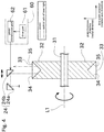
- Fig. 1 is a perspective view of the laser processing device 1.
- the laser processing device 1 is a device for processing a workpiece (irradiation target) 100 by irradiating the workpiece 100 with a laser light.
- the workpiece 100 in this embodiment is a plate shape object, for example, CFRP (carbon fiber reinforced plastic).
- CFRP carbon fiber reinforced plastic
- the workpiece 100 may be made of other materials.
- the workpiece 100 is not limited to plate shaped object.
- the workpiece 100 may be in the form of a block, for example.
- the thickness direction of the workpiece 100 is defined as the plate thickness direction.
- the laser processing device 1 of the present embodiment performs ablation processing by evaporating the workpiece 100 by irradiating the workpiece 100 with the laser light.
- the laser processing device 1 may perform thermal processing by melting the workpiece 100 by the heat of the laser light.
- the laser processing device 1 processes the workpiece 100 by cutting it with a laser light.
- the processing performed by the laser processing device 1 on the workpiece 100 is not limited to cutting, the laser processing device 1 may, for example, perform a process of removing the surface of the workpiece 100 along a predetermined shape.
- the laser light may be visible light or electromagnetic wave which has wavelength band other than visible light.
- the meaning of a word "light” includes not only visible light but also various electromagnetic waves with a wider wavelength band.
- the laser processing device 1 is provided with a transport unit 11, a laser generator (light source) 12, and a light guide device 13.
- the transport unit 11 is a belt conveyor.
- the transport unit 11 transports the workpiece 100 place on the transport unit 10 in a predetermined direction.
- the transport unit 11 can transport the workpiece 100 in a transport direction and can stop it at a predetermined position.
- the transport unit 11 transports the workpiece 100 and stops the workpiece 100 at a position to perform laser processing.
- the transport unit 11 may be a roller conveyor, or it may be configured to grasp and transport the workpiece 100.
- the transport unit 11 may be omitted, and the workpiece 100, which is fixed so as not to move, may be processed by irradiating a laser light onto the workpiece 100.
- the laser generator 12 generates a pulsed laser with a short time width by using pulsed oscillation. Although a time interval of the pulsed laser is not limited, the laser generator 12 generates the laser light at short time intervals, such as on the order of nanoseconds, picoseconds, or femtoseconds, for example.
- the laser generator 12 may generate a CW laser by using continuous wave oscillation.
- the light guide device 13 guides the laser light generated by the laser generator 12 and irradiates the workpiece 100.
- the light guide device 13 cuts the workpiece 100 by guiding the laser light so that the focused laser light is irradiated on the surface of the workpiece 100.
- the light guide device 13 includes a first light guide part 20, a polygon mirror 30, and a second light guide part 40. At least some of these optical components are located inside a housing of the light guide device 13.
- the first light guide part 20 includes optical components that guide the laser light generated by the laser generator 12 to the polygon mirror 30.
- the first light guide part 20 is provided with an introductory lens 21, an introductory prism 22, a first introductory mirror 23, and a second introductory mirror 24, in order from the laser generator 12 side along the optical path of the laser light.
- the introductory lens 21 focuses the laser light generated by the laser generator 12 at the focus point.
- the introductory prism 22, the first introductory mirror 23, and the second introductory mirror 24 guide the laser light passed through the introductory lens 21 to the polygon mirror 30.
- the introductory prism 22, the first introductory mirror 23, and the second introductory mirror 24 comprise an optical unit.
- the optical unit bends the optical path upstream of the polygon mirror 30 to provide an optical path length necessary to position the focus point on the surface of the workpiece 100.
- the optical components comprising the first light guide part 20 shown in this embodiment can be omitted accordingly.
- Other prisms or mirrors may be added between the introductory lens 21 and the polygon mirror 30, as appropriate.
- the polygon mirror 30 is formed as a whole in a regular polygonal shape (in this embodiment, a regular octagonal shape).
- the polygon mirror 30 can be rotated at a constant angular speed, for example, by transmission of power from the electric motor (not shown).
- the rotation axis direction of the polygon mirror 30 is the same as the viewpoint direction (viewing angle) of Fig. 2 (i.e., the viewpoint direction for the polygon mirror 30 to appear as a regular polygon).
- the laser light generated by the laser generator 12 and reflected by the polygon mirror 30 is guided by the second light guide part 40 and irradiated on the workpiece 100.
- the irradiation position of the laser light is changed according to the angle of the reflective surface of the polygon mirror 30.
- the laser light from the laser generator 12 is deflected and the reflection angle of the laser light at the polygon mirror 30 is changed.
- This causes a laser light to be scanned on the workpiece 100.
- Scan is to change the irradiation position of light such as laser light in a certain direction.
- the irradiated area contains irradiation of the plurality of laser lights is expanded in a specific direction as the laser light is scanned.
- the scanning direction of the laser light is simply referred to as the "scanning direction".
- the workpiece 100 is cut along the scanning direction.
- the polygon mirror 30 emits laser light introduced by the second introductory mirror 24 and the polygon mirror 30 rotates so that the laser light introduced by the second introductory mirror 24 is moved at a constant angularly speed.
- the second light guide part 40 reflects the light emitted from the polygon mirror 30 and guides the light to the scanning line 91. As the rotation angle of the polygon mirror 30 changes, the irradiation position moves sequentially in the scanning direction along the scanning line 91 on the workpiece 100.
- the second light guide part 40 has a plurality of reflective surfaces, which reflect the laser light reflected by the polygon mirror 30 and guide it to the surface of the workpiece 100 as appropriate.
- the second light guide part 40 has a plurality of first irradiating mirrors 41 and a plurality of second irradiating mirrors 42.
- Fig. 3 is a schematic figure showing a positional relationship between a deflection center C, a first irradiating mirror 41, a second irradiating mirror 42, and a scanning line 91.
- the focus point of the laser light draws an arc-shaped trajectory as the rotation angle of the polygon mirror 30 changes by an amount corresponding to one side of the regular polygon.
- the center of this trajectory is the deflection center C, where the laser light is deflected by the polygon mirror 30, and the radius of the trajectory is the optical path length from said deflection center C to the focus point.
- the scanning line 91 extends in a straight line in the scanning direction, unlike the arc-shaped trajectory.
- the optical path length from the deflection center C mentioned above to any irradiation position on the scanning line 91 is not constant and varies according to the irradiation position.
- a second light guide part 40 is provided to solve this problem, reflecting the laser light from the polygon mirror 30 at least twice before the workpiece 100 (scanning line 91).
- the second light guide part 40 is arranged so that the optical path length from the reflective surface of the polygon mirror 30 to any irradiation position on the scanning line 91 on the workpiece 100 is approximately constant for all irradiation positions, respectively.
- the second light guide part 40 in the present embodiment has a first irradiating mirror 41 which reflects the laser light from the polygon mirror 30, and a second irradiating mirror 42 which further reflects the laser light from the first irradiating mirror 41.
- the second light guide part 40 reflects the laser light from the polygon mirror 30 twice.
- the second light guide part 40 includes a first irradiating mirror 41 and a second irradiating mirror 42.
- the second light guide part 40 may be configured with optical components arranged such that the laser light is reflected three or more times.
- the focus point of trajectory of the laser light is an arc (hereinafter referred to as a virtual arc) around the deflection center C as the emitting angle of light output changes.
- the radius R of the virtual arc is the optical path length from the deflection center C to the focus point.
- the first irradiating mirror 41 and the second irradiating mirror 42 bend the optical path from the deflection center C to the focus point, thereby transforming the virtual arc to extend generally in a straight line in the scanning direction on the workpiece 100.
- the positions of the divided arcs DA1, DA2,..., which split the virtual arcs are transformed by the second light guide part 40 so that the orientation of each of its strings VC1, VC2,... is approximately equal to the scanning line 91.
- the first irradiating mirror 41 and the second irradiating mirror 42 each have a plurality of reflective surfaces.
- the split angle range is a range of the emitting angle of the laser light from the polygon mirror 30 divided into multiple ranges.
- a split arc DA1, DA2, ... is a trajectory drawn by a point (focus point) at a certain distance from the laser generator 12 along the light as the emitting angle of the light changes in the split angle range. In such a way that the split arcs VC1, VC2, ... of the split arcs DA1, DA2, ... are in the same direction as the scanning direction (so that they line up in the scanning direction), the first irradiating mirror 41 and the second irradiating mirror 42 reflect the light multiple times.
- the specific method for transforming the position of the virtual arc to match the scanning line 91 will be briefly described. First, by dividing the virtual arc into equally spaced portions, a plurality of split arcs DA1, DA2,... are obtained. Next, we obtain a plurality of virtual strings VC1, VC2, ... corresponding to each of the plurality of split arcs DA1, DA2, ... Next, the positions and directions of the reflective surfaces possessed by the first irradiating mirror 41 and the second irradiating mirror 42 respectively are determined so that a plurality of virtual strings VC1, VC2, ... are sequentially lined up in a straight line in the scanning direction on the workpiece 100.
- the two points at both ends of the split arc DA1, DA2,... are relocated on the scanning line 91, and the split arc DA1, DA2,... (i.e., the curve connecting two points) is relocated downstream in the optical axis direction from the scanning line 91.
- the focus point of the laser light moves along the split arc DA1, DA2, ... with the position transformed in this way.
- the split arcs DA1, DA2,... approximate the corresponding virtual strings VC1, VC2,... with high accuracy. Therefore, the optical path length from the deflection center C of the polygon mirror 30 to any irradiation position on the scanning line 91 is approximately constant over all irradiation positions. Since the split arcs DA1, DA2,... are in high accuracy approximation with the corresponding virtual strings VC1, VC2,..., the behavior of the focus point in the respective split arcs DA1, DA2,... approximates with high accuracy the constant velocity linear motion along the scanning line 91.
- the distance between the midpoint of the virtual string VC1, VC2, ... and the midpoint of the split arc DA1, DA2, ... decreases, and the locus of focus point approaches the virtual string VC1, VC2, ... This allows for a high degree of consistency in optical path length.
- the number of divisions can be determined as appropriate depending on the error allowed by the light guide device 13.
- the second light guide part 40 allows the surface of the workpiece 100 to be properly processed by the second light guide part 40 because the focus point of the laser light is located on the surface of the workpiece 100.
- the beam diameter at the processing point is very small because the workpiece 100 is processed with a short-pulse laser light to concentrate the energy. Therefore, depending on the material and thickness of the workpiece 100, it may be necessary to irradiate the laser light at the same position multiple times. However, in this case, the shape of the groove formed in the workpiece 100 by the laser light may be curved, causing process saturation and making it impossible to cut.
- the process saturation is a phenomenon in which the energy of the laser does not transfer to ablation, but changes to heat.
- the workpiece 100 is processed by distributing the scanning line 91, which is the irradiation position of the laser light, by the light guide device 13.
- This configuration will be described below with reference to Fig. 4 and Fig. 5 .
- Fig. 4 shows a cross-sectional view of a configuration in which the optical axis of the laser light incident on the polygon mirror 30 is changed along the rotation axis direction.
- Fig. 5 shows that by changing the optical axis of the laser light incident on the polygon mirror 30 along the rotation axis direction, the amount of offset of the reflected light with respect to the incident light is changed.
- the polygon mirror 30 has a rotation shaft 31, a plurality of supports 32, and a plurality of reflective parts 33.
- the rotation shaft 31 is a shaft and the like for rotating the polygon mirror 30, as described above.
- the rotation shaft 31 is driven by the above-described electric motor (not shown) with the rotation axis line L1 as the rotation center.
- the direction parallel to the rotation axis line L1 is called the rotation axis direction.
- the plurality of supports 32 are fixed to the rotation shaft 31 and rotate integrally with the rotation shaft 31.
- the direction that spreads outward radially around the rotation axis line L1 is called the radial direction.
- One side in the radial direction that extends away from the rotation axis line L1 is referred to as the outside of the radial direction, and the other side in the radial direction approaching the rotation axis line L1 is referred to as the inside of the radial direction.
- the supports 32 are arranged in such a way that when viewed in the rotation axis direction, the outer edges in the radial direction constitute each side of a regular polygon.
- the support 32 is provided in the same number as the vertices of the regular polygon mirror 30.
- a triangular-shaped groove is formed at the outer end of the support 32 in the radial direction, as shown in FIG. 4 and Fig. 5 , and a reflective part 33 is disposed in this groove.
- the reflective part 33 is a right-angle isosceles triangle-shaped prism with a base angle of 45 degrees.
- the reflective part 33 is arranged so that the oblique side is perpendicular to the incident laser light.
- the two sides except the oblique side of the reflective part 33 function as the first reflective surfaces 34 and second reflective surface 35, respectively.
- the travel direction of the laser light incident on the reflective part 33 is changed by reflection as shown by the chain line in Fig. 4 .
- the explanation of the change in the scanning direction among the changes in the travel direction of the laser light will be omitted.
- the laser light incident on the reflective part 33 travels inside of the radial direction.
- the laser light is reflected at the first reflective surface 34, which changes the travel direction by 90 degrees, and the reflected laser light travel to the second reflective surface 35.
- the laser light is reflected again at the second reflective surface 35, which changes the travel direction by 90 degrees. That is, the incident and reflected light of the laser light are parallel, and their positions of the rotation axis direction are different.
- the second introductory mirror 24 comprises a first bend mirror 24a and a second bend mirror 24b.
- the second bend mirror 24b is disposed so that the angle of the second bend mirror 24b is parallel to the first reflective surface 34.
- the second bend mirror 24b is disposed to form 45 degrees with respect to both the plate thickness direction and the rotation axis direction.
- the first bend mirror 24a is disposed so that the disposal angle of the first bend mirror 24a is perpendicular to the disposal angle of the second bend mirror 24b.
- the laser light emitted from the first introductory mirror 23 is injected into the first bend mirror 24a.
- This laser light is reflected by the first bend mirror 24a, which changes the travel direction by 90 degrees and travel to the second bend mirror 24b.
- the laser light is then reflected again by the second bend mirror 24b, which changes the travel direction by 90 degrees. That is, the laser light incident to the second introductory mirror 24 and the laser light reflected by the second introductory mirror 24 are parallel to each other and have different positions in the rotation axis direction.
- the second bend mirror 24b of this embodiment is configured to move in the rotation axis direction.
- the laser processing device 1 is equipped with an adjustment part 60.
- the adjustment part 60 has a drive part 61 and a power transmission part 62.
- the power generated by the drive part 61 is transmitted to the second bend mirror 24b via the power transmission part 62, which moves the second bend mirror 24b in the rotation axis direction.
- the position of the second bend mirror 24b in the rotation axis direction By changing the position of the second bend mirror 24b in the rotation axis direction, the position where the laser light is reflected in the rotation axis direction is changed. Therefore, the position of the optical axis of the light incident on the polygon mirror 30 (first reflective surface 34) also changes. Specifically, as shown in Fig. 5 , when the position of the second bend mirror 24b in the rotation axis direction changes a distance L to one side (the right side of Fig. 5 ), the incident position of the first reflective surface 34 changes a distance L to one side. Therefore, the reflection position of the second reflective surface 35 changes a distance L to the other side. Thus, by moving the second bend mirror 24b in the rotation axis direction, the position of the optical axis of the laser light emitted from the polygon mirror 30 (second reflective surface 35) in the rotation axis direction can be changed.
- the rotation axis direction of the polygon mirror 30 is the same as the line width direction (width direction) of the irradiated area of the laser light on the workpiece 100. Therefore, if the position of the reflective part 33 is different, the laser light will be irradiated at a distributed (change in position) position in the line width direction.
- the irradiated area of each pulse of laser light reflected by one reflective part 33 of the polygon mirror 30 is circular in shape. By combining these circular irradiated areas in the same direction, a linearly spread irradiated area in a certain direction is achieved.
- the second bend mirror 24b By moving the second bend mirror 24b in the rotation axis direction, the position of the laser light irradiated on the workpiece 100 in the line width direction is changed, as shown in the lower view of Fig. 6 . Therefore, the apparent line width of the irradiated area of the laser light can be made wider. This allows for a wider processing width. In addition, since the laser light can be prevented from being continuously irradiated at the same position only, the above-mentioned process saturation is unlikely to occur, and the workpiece 100 can be reliably cut in a short time.
- the timing and amount of movement of the second bend mirror 24b can be various.
- the second bend mirror 24b is used as following.
- a processing width is set in advance in the laser processing device 1.
- the second bend mirror 24b is moved so that the apparent line width above is equal to the processing width.
- Periodic means moving the second bend mirror 24b by a predetermined amount of movement according to the rotation phase or time of the polygon mirror 30, and repeating the same.
- the purpose of this embodiment is not to align the irradiated position of the laser light (that is, not to correct the misalignment). Therefore, unlike PTL 2, a sensor to detect the position of the laser light is not required.
- the adjustment part 60 has only the function of adjusting the position in the rotation axis direction of the laser light incident on the reflective part 33 in synchronization with the rotational phase of the polygon mirror 30 (i.e., in accordance with a prepared program in advance). In other words, the laser processing device 1 does not have a function such as that of PTL 2 to change the position of the laser light in response to the sensor.
- the position of the optical axis of the laser light incident on the first reflective surface 34 may be set for each reflective part 33 of the polygon mirror 30. Specifically, after reflecting the laser light at one reflective part 33 of the polygon mirror 30, the second bend mirror 24b is moved to reflect the laser light at the next reflective part 33.
- a function can be achieved by a program that can set the position of the laser light in the width direction at any number of passes (at any timing).
- the position of the surface of the workpiece 100 (i.e., the processing position) is changed by evaporating or melting the workpiece 100 by the laser light to remove it.
- the processing position changes in the direction of the thickness of the plate and, in detail, downstream of the direction of laser irradiation.
- the position of the focus point of the laser light relative to the processing position of the workpiece 100 is changed to bring the focus point and processing position closer relative to each other.
- the method of changing the relative position of the focus point of the laser light includes, for example, a method of moving the workpiece 100 upstream in the direction of the laser irradiation. This allows the laser light to be focused at the processing position, thus allowing the workpiece 100 to be processed efficiently.
- the width of the processing grooves is narrow. Therefore, when the focus point is changed, the laser light may hit the edge E when the processing groove becomes deeper. In this case, energy is consumed at this edge E, which may reduce the heat density at the focus point and cause process saturation, making it difficult to process.
- the width of the processing groove can be widened and the apparent line width of the irradiated area of the laser light can be adjusted. Therefore, by varying the focus point, the beam in the middle of the apparent line width is less affected by the edge E. As a result, process saturation can be prevented and processing can continue properly.
- the depth of the current processing groove of the workpiece 100 In order to control the focus point of the laser light relative to the processing position of the workpiece 100 according to the depth of the processing groove of the workpiece 100, the depth of the current processing groove of the workpiece 100 must be estimated or detected. Specifically, it is possible to estimate the depth of the processing groove of the workpiece 100 based on the number of times the laser is irradiated and the time elapsed since the start of processing, or the depth of the processing groove of the workpiece 100 can be detected by detecting the shape of the workpiece 100 by light or sound waves or the like. By using the depth of the processing groove obtained in this way, the focus point of the laser light can be adjusted according to the depth of the processing groove. The number of times the focus point position may be changed once or multiple times for a single laser process (in this embodiment, one workpiece 100 is cut).
- the light guide device 13 of this embodiment includes the first light guide part 20, the polygon mirror 30, the second light guide part 40, and the adjustment part 60.
- the first light guide part 20 reflects and guides the laser light emitted from the laser generator 12.
- the polygon mirror 30 is configured to be rotatable.
- the polygon mirror 30 has a plurality of reflective parts 33 disposed so as to constitute a regular polygonal reflective surface when viewed in the rotation axis direction.
- the laser light guided by the first light guide part 20 is reflected by the rotating reflective part 33.
- the second light guide part 40 reflects the laser light reflected at the reflective part 33 of the polygon mirror 30 and guides the light so that the laser light is irradiated to the workpiece 100 at each of the reflective parts 33.
- the adjustment part 60 adjusts the position of the light incident on the polygon mirror 30 in the rotation axis direction of the optical axis by changing at least one of the positions and orientations of the optical components included in the first light guide part 20.
- the reflective part 33 of the polygon mirror 30 is configured to reflect the incident laser light so that the optical axis of the incident light is offset in the rotation axis direction.
- the adjustment part adjusts the position of the optical axis of the light incident on the polygon mirror 30 in the rotation axis direction, thereby changing a position of the light irradiated on the workpiece 100 in a line width direction of the light, the workpiece 100 is irradiated with the light while a position of the light irradiated on the workpiece 100 in the line width direction.
- the position of the optical axis of the light incident on the reflective part 33 differs in the rotation axis direction
- the position of the light irradiated on the workpiece 100 also differs. Therefore, the position of the irradiated area can be distributed in the width direction without moving the workpiece 100.
- the adjustment part 60 changes the position of the optical axis of the light incident on the polygon mirror 30 in the rotation axis direction based on a preset value.
- the adjustment part periodically changes the position of the optical axis of the light incident on the polygon mirror 30 in the rotation axis direction.
- the laser processing device 1 of this embodiment includes the light guide device 13 and the laser generator 12.
- the laser generator 12 generates the laser light.
- the workpiece 100 is plate shaped.
- the workpiece 100 is irradiated with a laser light multiple times so that the irradiated areas overlap.
- the laser processing device 1 brings the focus point of the laser light relatively close to the processing position of the workpiece 100, depending on the depth of the processing groove of the workpiece 100.
- the position in the rotation axis direction can be adjusted for all reflective parts 33 provided by the polygon mirror 30. In fact, it is not necessary to adjust the position of all the reflective parts 33. However, the position of all the reflective parts 33 in the rotation axis direction may be adjusted.
- the position of the second introductory mirror 24 among the first light guide part 20 is changed.
- the position or orientation of the optical components different from the second introductory mirror 24 may be changed to change the position of the laser light in the rotation axis direction of the optical axis.
- the reflective part 33 is a prism, but it may be configured with a mirror disposed at a position corresponding to the first reflective surface 34 and the second reflective surface 35, respectively.
- the light guide device 13 can also be applied to other devices, such as an image forming apparatus, for example.
- the image forming device is a device that forms a toner image by irradiating a photosensitive drum with light.
- a light source other than a laser light e.g., an LED lamp
Abstract
Description
- The present invention mainly relates to a light guide device for scanning a light using a mirror having a plurality of reflective surfaces.
- Conventionally, a technology of scanning a light from a light source along a scanning line which is a straight line has been widely used in image forming devices and laser processing devices.
PTL 1 and PTL 2 disclose an optical scanning apparatus included in the above devices. - The optical scanning apparatus of
PTL 1 comprises a light projecting means and an optical reflection means. The light projecting means has a polygon mirror. A Light incident from a certain direction is reflected on a reflective surface of each side of a regular polygon shape of the rotating polygon mirror. This causes the polygon mirror to emit light while rotating. The optical reflection means reflects the light emitted from the light projecting means by a plurality of reflective part. The optical reflection means guides the light to any irradiated point on the scanning line. - The optical axis corrector of
PTL 1 scans light by using a polygon mirror. The optical axis corrector has a function of correcting the position of the optical axis of the irradiation light. Specifically, the optical axis corrector comprises a position sensor, a movable mirror, and a control unit. The position sensor detects the misalignment of an optical axis of an irradiation light. The movable mirror changes the position of the optical axis of the light incident on the polygon mirror by changing the angle of the mirror. The control unit changes the angle of the movable mirror so that the misalignment detected by the position sensor is reduced based on the misalignment. -
- PTL1: Japanese Patent No.
5401629 - PTL2: Japanese Patent Application Laid-Open No.
1993-307148 - In the situation where the irradiated area is processed by irradiating the irradiation target with the light so that the irradiated area is circular or point-shaped, or in the situation where information on the irradiation target is read, it may be desirable to disperse (offset) the position of the irradiated area without moving the irradiation target.
PTL 1 does not disclose a configuration to achieve that. Since the purpose of PTL 2 is to correct the misalignment of the optical axis, PTL 2 does not disclose a configuration suitable for the above desire. - The present invention has been made in view of the above circumstances, and its main object is to provide a light guide device capable of distributing a position of an irradiated area in a line width direction without moving an irradiation target.
- Problems to be solved by the present invention are as described above. Solutions to the problems and advantageous effects thereof will now be described.
- An aspect of the present invention provides a light guide device as follows. The light guide device includes a first light guide part, a polygon mirror, a second light guide part, and an adjustment part. The first light guide part reflects and guides a light emitted from a light source. The polygon mirror is configured to be rotatable. The polygon mirror includes a plurality of reflective parts, the reflective parts being arranged to form a regular polygonal reflective surface when viewed in a rotation axis direction. The light guided by the first light guide part is reflected by the rotating reflective part. The second light guide part reflects the light reflected by the reflective part of the polygon mirror and guides the light so that the light is irradiated to an irradiation target at each of the reflective parts The adjustment part changes at least one of a position and an orientation of an optical component included in the first light guide part. Thereby, the adjustment part adjusts a position of an optical axis of a light incident on the polygon mirror in a rotation axis direction. The reflective part of the polygon mirror is configured to reflect the incident light so that the optical axis of the incident light is offset in the rotation axis direction. The adjustment part adjusts the position of the optical axis of the light incident on the polygon mirror in the rotation axis direction. This changes a position of the light irradiated on the irradiation target in a line width direction of the light. The irradiation target is irradiated with the light while a position of the light irradiated on the irradiation target in a line width direction.
- As a result, if the position of the optical axis of the light incident on the reflective part differs in the rotation axis direction, the position of the light irradiated on the irradiation target also differs. Therefore, the position of the irradiated area can be distributed in the width direction without moving the irradiation target.
- According to the present invention, it is possible to realize a light guide device capable of distributing a position of an irradiated area in a width direction without moving an irradiation target.
-
- [
Fig. 1 ] A perspective view of a laser processing device according to one embodiment of the present invention. - [
Fig. 2 ] A figure of an optical path of a laser light emitted from a laser generator to a workpiece. - [
Fig. 3 ] A schematic figure showing a positional relationship between deflection center of a polygon mirror, a first irradiating mirror, a second irradiating mirror, and a position of a scanning line. - [
Fig. 4 ] A cross-sectional view of a configuration in which an optical axis of a laser light incident on a polygon mirror is changed along a rotation axis direction. - [
Fig. 5 ] A figure showing that an amount of offset of the reflected light is changed relative to an incident light by changing an optical axis of a laser light incident on a polygon mirror along a rotation axis direction. - [
Fig. 6 ] A figure for explaining becoming wider of an apparent line width of a laser light. - [
Fig. 7 ] A figure showing that a position of a focus point of a laser light is changed in a thickness direction depending on a processing status of a workpiece. - Next, embodiments of the present invention will be described with reference to the drawings. First, the configuration of a
laser processing device 1 will be described with reference toFig. 1. Fig. 1 is a perspective view of thelaser processing device 1. Thelaser processing device 1 is a device for processing a workpiece (irradiation target) 100 by irradiating theworkpiece 100 with a laser light. - The
workpiece 100 in this embodiment is a plate shape object, for example, CFRP (carbon fiber reinforced plastic). Theworkpiece 100 may be made of other materials. Theworkpiece 100 is not limited to plate shaped object. Theworkpiece 100 may be in the form of a block, for example. The thickness direction of theworkpiece 100 is defined as the plate thickness direction. - The
laser processing device 1 of the present embodiment performs ablation processing by evaporating theworkpiece 100 by irradiating theworkpiece 100 with the laser light. Thelaser processing device 1 may perform thermal processing by melting theworkpiece 100 by the heat of the laser light. Thelaser processing device 1 processes theworkpiece 100 by cutting it with a laser light. The processing performed by thelaser processing device 1 on theworkpiece 100 is not limited to cutting, thelaser processing device 1 may, for example, perform a process of removing the surface of theworkpiece 100 along a predetermined shape. - The laser light may be visible light or electromagnetic wave which has wavelength band other than visible light. In this embodiment, the meaning of a word "light" includes not only visible light but also various electromagnetic waves with a wider wavelength band.
- As shown in
Fig. 1 , thelaser processing device 1 is provided with atransport unit 11, a laser generator (light source) 12, and alight guide device 13. - The
transport unit 11 is a belt conveyor. Thetransport unit 11 transports theworkpiece 100 place on the transport unit 10 in a predetermined direction. Thetransport unit 11 can transport theworkpiece 100 in a transport direction and can stop it at a predetermined position. Thetransport unit 11 transports theworkpiece 100 and stops theworkpiece 100 at a position to perform laser processing. Thetransport unit 11 may be a roller conveyor, or it may be configured to grasp and transport theworkpiece 100. Thetransport unit 11 may be omitted, and theworkpiece 100, which is fixed so as not to move, may be processed by irradiating a laser light onto theworkpiece 100. - The
laser generator 12 generates a pulsed laser with a short time width by using pulsed oscillation. Although a time interval of the pulsed laser is not limited, thelaser generator 12 generates the laser light at short time intervals, such as on the order of nanoseconds, picoseconds, or femtoseconds, for example. Thelaser generator 12 may generate a CW laser by using continuous wave oscillation. - The
light guide device 13 guides the laser light generated by thelaser generator 12 and irradiates theworkpiece 100. Thelight guide device 13 cuts theworkpiece 100 by guiding the laser light so that the focused laser light is irradiated on the surface of theworkpiece 100. - Referring to
Fig. 2 andFig. 3 , thelight guide device 13 will be described in detail below. As shown inFig. 2 , thelight guide device 13 includes a firstlight guide part 20, apolygon mirror 30, and a secondlight guide part 40. At least some of these optical components are located inside a housing of thelight guide device 13. - The first
light guide part 20 includes optical components that guide the laser light generated by thelaser generator 12 to thepolygon mirror 30. The firstlight guide part 20 is provided with anintroductory lens 21, anintroductory prism 22, a firstintroductory mirror 23, and a secondintroductory mirror 24, in order from thelaser generator 12 side along the optical path of the laser light. - The
introductory lens 21 focuses the laser light generated by thelaser generator 12 at the focus point. Theintroductory prism 22, the firstintroductory mirror 23, and the secondintroductory mirror 24 guide the laser light passed through theintroductory lens 21 to thepolygon mirror 30. Theintroductory prism 22, the firstintroductory mirror 23, and the secondintroductory mirror 24 comprise an optical unit. The optical unit bends the optical path upstream of thepolygon mirror 30 to provide an optical path length necessary to position the focus point on the surface of theworkpiece 100. The optical components comprising the firstlight guide part 20 shown in this embodiment can be omitted accordingly. Other prisms or mirrors may be added between theintroductory lens 21 and thepolygon mirror 30, as appropriate. - As shown in
Fig. 2 , thepolygon mirror 30 is formed as a whole in a regular polygonal shape (in this embodiment, a regular octagonal shape). Thepolygon mirror 30 can be rotated at a constant angular speed, for example, by transmission of power from the electric motor (not shown). The rotation axis direction of thepolygon mirror 30 is the same as the viewpoint direction (viewing angle) ofFig. 2 (i.e., the viewpoint direction for thepolygon mirror 30 to appear as a regular polygon). - The laser light generated by the
laser generator 12 and reflected by thepolygon mirror 30 is guided by the secondlight guide part 40 and irradiated on theworkpiece 100. The irradiation position of the laser light is changed according to the angle of the reflective surface of thepolygon mirror 30. In other words, as thepolygon mirror 30 rotates, the laser light from thelaser generator 12 is deflected and the reflection angle of the laser light at thepolygon mirror 30 is changed. This causes a laser light to be scanned on theworkpiece 100. Scan is to change the irradiation position of light such as laser light in a certain direction. In the present embodiment, the irradiated area contains irradiation of the plurality of laser lights is expanded in a specific direction as the laser light is scanned. In the following, the scanning direction of the laser light is simply referred to as the "scanning direction". Theworkpiece 100 is cut along the scanning direction. - The
polygon mirror 30 emits laser light introduced by the secondintroductory mirror 24 and thepolygon mirror 30 rotates so that the laser light introduced by the secondintroductory mirror 24 is moved at a constant angularly speed. The secondlight guide part 40 reflects the light emitted from thepolygon mirror 30 and guides the light to thescanning line 91. As the rotation angle of thepolygon mirror 30 changes, the irradiation position moves sequentially in the scanning direction along thescanning line 91 on theworkpiece 100. - The second
light guide part 40 has a plurality of reflective surfaces, which reflect the laser light reflected by thepolygon mirror 30 and guide it to the surface of theworkpiece 100 as appropriate. The secondlight guide part 40 has a plurality of first irradiating mirrors 41 and a plurality of second irradiating mirrors 42. - The arrangement and function of the second
light guide part 40 will be described below with reference toFig. 3. Fig. 3 is a schematic figure showing a positional relationship between a deflection center C, afirst irradiating mirror 41, asecond irradiating mirror 42, and ascanning line 91. - If the second
light guide part 40 is not present, as shown in the upper view ofFig. 3 , the focus point of the laser light (a point distance away from thelaser generator 12 along the optical path) draws an arc-shaped trajectory as the rotation angle of thepolygon mirror 30 changes by an amount corresponding to one side of the regular polygon. The center of this trajectory is the deflection center C, where the laser light is deflected by thepolygon mirror 30, and the radius of the trajectory is the optical path length from said deflection center C to the focus point. On the other hand, thescanning line 91 extends in a straight line in the scanning direction, unlike the arc-shaped trajectory. As a result, the distance from the irradiation position on thescanning line 91 to the focus point changes according to the irradiation position. Therefore, considering the optical path length from the deflection center C mentioned above to any irradiation position on thescanning line 91, the optical path length is not constant and varies according to the irradiation position. - A second
light guide part 40 is provided to solve this problem, reflecting the laser light from thepolygon mirror 30 at least twice before the workpiece 100 (scanning line 91). The secondlight guide part 40 is arranged so that the optical path length from the reflective surface of thepolygon mirror 30 to any irradiation position on thescanning line 91 on theworkpiece 100 is approximately constant for all irradiation positions, respectively. - The second
light guide part 40 in the present embodiment has afirst irradiating mirror 41 which reflects the laser light from thepolygon mirror 30, and asecond irradiating mirror 42 which further reflects the laser light from thefirst irradiating mirror 41. In other words, the secondlight guide part 40 reflects the laser light from thepolygon mirror 30 twice. The secondlight guide part 40 includes afirst irradiating mirror 41 and asecond irradiating mirror 42. The secondlight guide part 40 may be configured with optical components arranged such that the laser light is reflected three or more times. - As described above, if the
first irradiating mirror 41 and thesecond irradiating mirror 42 were not present, the focus point of trajectory of the laser light is an arc (hereinafter referred to as a virtual arc) around the deflection center C as the emitting angle of light output changes. The radius R of the virtual arc is the optical path length from the deflection center C to the focus point. Thefirst irradiating mirror 41 and thesecond irradiating mirror 42 bend the optical path from the deflection center C to the focus point, thereby transforming the virtual arc to extend generally in a straight line in the scanning direction on theworkpiece 100. In detail, the positions of the divided arcs DA1, DA2,..., which split the virtual arcs are transformed by the secondlight guide part 40 so that the orientation of each of its strings VC1, VC2,... is approximately equal to thescanning line 91. - The
first irradiating mirror 41 and thesecond irradiating mirror 42 each have a plurality of reflective surfaces. The split angle range is a range of the emitting angle of the laser light from thepolygon mirror 30 divided into multiple ranges. A split arc DA1, DA2, ... is a trajectory drawn by a point (focus point) at a certain distance from thelaser generator 12 along the light as the emitting angle of the light changes in the split angle range. In such a way that the split arcs VC1, VC2, ... of the split arcs DA1, DA2, ... are in the same direction as the scanning direction (so that they line up in the scanning direction), thefirst irradiating mirror 41 and thesecond irradiating mirror 42 reflect the light multiple times. - The specific method for transforming the position of the virtual arc to match the
scanning line 91 will be briefly described. First, by dividing the virtual arc into equally spaced portions, a plurality of split arcs DA1, DA2,... are obtained. Next, we obtain a plurality of virtual strings VC1, VC2, ... corresponding to each of the plurality of split arcs DA1, DA2, ... Next, the positions and directions of the reflective surfaces possessed by thefirst irradiating mirror 41 and thesecond irradiating mirror 42 respectively are determined so that a plurality of virtual strings VC1, VC2, ... are sequentially lined up in a straight line in the scanning direction on theworkpiece 100. - When the
scanning line 91 is formed in this manner, the two points at both ends of the split arc DA1, DA2,... are relocated on thescanning line 91, and the split arc DA1, DA2,... (i.e., the curve connecting two points) is relocated downstream in the optical axis direction from thescanning line 91. The focus point of the laser light moves along the split arc DA1, DA2, ... with the position transformed in this way. - When the virtual arc is divided to multiple split arcs DA1, DA2,..., the split arcs DA1, DA2,... approximate the corresponding virtual strings VC1, VC2,... with high accuracy. Therefore, the optical path length from the deflection center C of the
polygon mirror 30 to any irradiation position on thescanning line 91 is approximately constant over all irradiation positions. Since the split arcs DA1, DA2,... are in high accuracy approximation with the corresponding virtual strings VC1, VC2,..., the behavior of the focus point in the respective split arcs DA1, DA2,... approximates with high accuracy the constant velocity linear motion along thescanning line 91. - As the number of divisions of the split arc DA1, DA2, ... increases, the distance between the midpoint of the virtual string VC1, VC2, ... and the midpoint of the split arc DA1, DA2, ... decreases, and the locus of focus point approaches the virtual string VC1, VC2, ... This allows for a high degree of consistency in optical path length. The number of divisions can be determined as appropriate depending on the error allowed by the
light guide device 13. - Thus, the second
light guide part 40 allows the surface of theworkpiece 100 to be properly processed by the secondlight guide part 40 because the focus point of the laser light is located on the surface of theworkpiece 100. - In the present embodiment, the beam diameter at the processing point is very small because the
workpiece 100 is processed with a short-pulse laser light to concentrate the energy. Therefore, depending on the material and thickness of theworkpiece 100, it may be necessary to irradiate the laser light at the same position multiple times. However, in this case, the shape of the groove formed in theworkpiece 100 by the laser light may be curved, causing process saturation and making it impossible to cut. The process saturation is a phenomenon in which the energy of the laser does not transfer to ablation, but changes to heat. - Considering the above, in the present embodiment, the
workpiece 100 is processed by distributing thescanning line 91, which is the irradiation position of the laser light, by thelight guide device 13. This configuration will be described below with reference toFig. 4 andFig. 5 .Fig. 4 shows a cross-sectional view of a configuration in which the optical axis of the laser light incident on thepolygon mirror 30 is changed along the rotation axis direction.Fig. 5 shows that by changing the optical axis of the laser light incident on thepolygon mirror 30 along the rotation axis direction, the amount of offset of the reflected light with respect to the incident light is changed. - As shown in
Fig. 4 , thepolygon mirror 30 has arotation shaft 31, a plurality ofsupports 32, and a plurality ofreflective parts 33. - The
rotation shaft 31 is a shaft and the like for rotating thepolygon mirror 30, as described above. Therotation shaft 31 is driven by the above-described electric motor (not shown) with the rotation axis line L1 as the rotation center. The direction parallel to the rotation axis line L1 is called the rotation axis direction. - The plurality of
supports 32 are fixed to therotation shaft 31 and rotate integrally with therotation shaft 31. The direction that spreads outward radially around the rotation axis line L1 is called the radial direction. One side in the radial direction that extends away from the rotation axis line L1 is referred to as the outside of the radial direction, and the other side in the radial direction approaching the rotation axis line L1 is referred to as the inside of the radial direction. The supports 32 are arranged in such a way that when viewed in the rotation axis direction, the outer edges in the radial direction constitute each side of a regular polygon. Thesupport 32 is provided in the same number as the vertices of theregular polygon mirror 30. A triangular-shaped groove is formed at the outer end of thesupport 32 in the radial direction, as shown inFIG. 4 andFig. 5 , and areflective part 33 is disposed in this groove. - The
reflective part 33 is a right-angle isosceles triangle-shaped prism with a base angle of 45 degrees. Thereflective part 33 is arranged so that the oblique side is perpendicular to the incident laser light. The two sides except the oblique side of thereflective part 33 function as the firstreflective surfaces 34 and secondreflective surface 35, respectively. - With this configuration, the travel direction of the laser light incident on the
reflective part 33 is changed by reflection as shown by the chain line inFig. 4 . In the following, the explanation of the change in the scanning direction among the changes in the travel direction of the laser light will be omitted. As shown inFig. 4 , the laser light incident on thereflective part 33 travels inside of the radial direction. The laser light is reflected at the firstreflective surface 34, which changes the travel direction by 90 degrees, and the reflected laser light travel to the secondreflective surface 35. The laser light is reflected again at the secondreflective surface 35, which changes the travel direction by 90 degrees. That is, the incident and reflected light of the laser light are parallel, and their positions of the rotation axis direction are different. - In the
laser processing device 1 of the present embodiment, the position of the optical axis of the light incident on the polygon mirror 30 (the first reflective surface 34) in the rotation axis direction can be adjusted. Specifically, as shown inFig. 4 , the secondintroductory mirror 24 comprises afirst bend mirror 24a and asecond bend mirror 24b. InFig. 4 (i.e., when viewed in the scanning direction), thesecond bend mirror 24b is disposed so that the angle of thesecond bend mirror 24b is parallel to the firstreflective surface 34. In other words, thesecond bend mirror 24b is disposed to form 45 degrees with respect to both the plate thickness direction and the rotation axis direction. Thefirst bend mirror 24a is disposed so that the disposal angle of thefirst bend mirror 24a is perpendicular to the disposal angle of thesecond bend mirror 24b. - The laser light emitted from the first
introductory mirror 23 is injected into thefirst bend mirror 24a. This laser light is reflected by thefirst bend mirror 24a, which changes the travel direction by 90 degrees and travel to thesecond bend mirror 24b. The laser light is then reflected again by thesecond bend mirror 24b, which changes the travel direction by 90 degrees. That is, the laser light incident to the secondintroductory mirror 24 and the laser light reflected by the secondintroductory mirror 24 are parallel to each other and have different positions in the rotation axis direction. - The
second bend mirror 24b of this embodiment is configured to move in the rotation axis direction. Specifically, as shown inFig. 4 , thelaser processing device 1 is equipped with anadjustment part 60. Theadjustment part 60 has adrive part 61 and apower transmission part 62. The power generated by thedrive part 61 is transmitted to thesecond bend mirror 24b via thepower transmission part 62, which moves thesecond bend mirror 24b in the rotation axis direction. - By changing the position of the
second bend mirror 24b in the rotation axis direction, the position where the laser light is reflected in the rotation axis direction is changed. Therefore, the position of the optical axis of the light incident on the polygon mirror 30 (first reflective surface 34) also changes. Specifically, as shown inFig. 5 , when the position of thesecond bend mirror 24b in the rotation axis direction changes a distance L to one side (the right side ofFig. 5 ), the incident position of the firstreflective surface 34 changes a distance L to one side. Therefore, the reflection position of the secondreflective surface 35 changes a distance L to the other side. Thus, by moving thesecond bend mirror 24b in the rotation axis direction, the position of the optical axis of the laser light emitted from the polygon mirror 30 (second reflective surface 35) in the rotation axis direction can be changed. - The rotation axis direction of the
polygon mirror 30 is the same as the line width direction (width direction) of the irradiated area of the laser light on theworkpiece 100. Therefore, if the position of thereflective part 33 is different, the laser light will be irradiated at a distributed (change in position) position in the line width direction. - Specifically, as shown in the upper view of
Fig. 6 , the irradiated area of each pulse of laser light reflected by onereflective part 33 of thepolygon mirror 30 is circular in shape. By combining these circular irradiated areas in the same direction, a linearly spread irradiated area in a certain direction is achieved. - By moving the
second bend mirror 24b in the rotation axis direction, the position of the laser light irradiated on theworkpiece 100 in the line width direction is changed, as shown in the lower view ofFig. 6 . Therefore, the apparent line width of the irradiated area of the laser light can be made wider. This allows for a wider processing width. In addition, since the laser light can be prevented from being continuously irradiated at the same position only, the above-mentioned process saturation is unlikely to occur, and theworkpiece 100 can be reliably cut in a short time. - The timing and amount of movement of the
second bend mirror 24b can be various. For example, thesecond bend mirror 24b is used as following. A processing width is set in advance in thelaser processing device 1. Thesecond bend mirror 24b is moved so that the apparent line width above is equal to the processing width. For example, by periodically moving thesecond bend mirror 24b, theworkpiece 100 can be processed evenly. Periodic means moving thesecond bend mirror 24b by a predetermined amount of movement according to the rotation phase or time of thepolygon mirror 30, and repeating the same. - The purpose of this embodiment is not to align the irradiated position of the laser light (that is, not to correct the misalignment). Therefore, unlike PTL 2, a sensor to detect the position of the laser light is not required. The
adjustment part 60 has only the function of adjusting the position in the rotation axis direction of the laser light incident on thereflective part 33 in synchronization with the rotational phase of the polygon mirror 30 (i.e., in accordance with a prepared program in advance). In other words, thelaser processing device 1 does not have a function such as that of PTL 2 to change the position of the laser light in response to the sensor. - If the
second bend mirror 24b can move at a high speed and the position control can be performed accurately, the position of the optical axis of the laser light incident on the firstreflective surface 34 may be set for eachreflective part 33 of thepolygon mirror 30. Specifically, after reflecting the laser light at onereflective part 33 of thepolygon mirror 30, thesecond bend mirror 24b is moved to reflect the laser light at the nextreflective part 33. Such a function can be achieved by a program that can set the position of the laser light in the width direction at any number of passes (at any timing). - Next, referring to
Fig. 7 , the configuration that brings the focus point of the laser light relatively close to the processing position of theworkpiece 100 according to the processing status of theworkpiece 100 will be described. - As shown in
Fig. 7 , the position of the surface of the workpiece 100 (i.e., the processing position) is changed by evaporating or melting theworkpiece 100 by the laser light to remove it. Specifically, the processing position changes in the direction of the thickness of the plate and, in detail, downstream of the direction of laser irradiation. - Therefore, in this embodiment, the position of the focus point of the laser light relative to the processing position of the
workpiece 100 is changed to bring the focus point and processing position closer relative to each other. The method of changing the relative position of the focus point of the laser light includes, for example, a method of moving theworkpiece 100 upstream in the direction of the laser irradiation. This allows the laser light to be focused at the processing position, thus allowing theworkpiece 100 to be processed efficiently. - In the conventional configuration where the irradiated area of the laser light cannot be changed in the line width direction, the width of the processing grooves is narrow. Therefore, when the focus point is changed, the laser light may hit the edge E when the processing groove becomes deeper. In this case, energy is consumed at this edge E, which may reduce the heat density at the focus point and cause process saturation, making it difficult to process.
- In contrast, in the present embodiment, since the irradiated area of the laser light is varied in the line width direction, the width of the processing groove can be widened and the apparent line width of the irradiated area of the laser light can be adjusted. Therefore, by varying the focus point, the beam in the middle of the apparent line width is less affected by the edge E. As a result, process saturation can be prevented and processing can continue properly.
- In order to control the focus point of the laser light relative to the processing position of the
workpiece 100 according to the depth of the processing groove of theworkpiece 100, the depth of the current processing groove of theworkpiece 100 must be estimated or detected. Specifically, it is possible to estimate the depth of the processing groove of theworkpiece 100 based on the number of times the laser is irradiated and the time elapsed since the start of processing, or the depth of the processing groove of theworkpiece 100 can be detected by detecting the shape of theworkpiece 100 by light or sound waves or the like. By using the depth of the processing groove obtained in this way, the focus point of the laser light can be adjusted according to the depth of the processing groove. The number of times the focus point position may be changed once or multiple times for a single laser process (in this embodiment, oneworkpiece 100 is cut). - As described above, the
light guide device 13 of this embodiment includes the firstlight guide part 20, thepolygon mirror 30, the secondlight guide part 40, and theadjustment part 60. The firstlight guide part 20 reflects and guides the laser light emitted from thelaser generator 12. Thepolygon mirror 30 is configured to be rotatable. Thepolygon mirror 30 has a plurality ofreflective parts 33 disposed so as to constitute a regular polygonal reflective surface when viewed in the rotation axis direction. The laser light guided by the firstlight guide part 20 is reflected by the rotatingreflective part 33. The secondlight guide part 40 reflects the laser light reflected at thereflective part 33 of thepolygon mirror 30 and guides the light so that the laser light is irradiated to theworkpiece 100 at each of thereflective parts 33. Theadjustment part 60 adjusts the position of the light incident on thepolygon mirror 30 in the rotation axis direction of the optical axis by changing at least one of the positions and orientations of the optical components included in the firstlight guide part 20. Thereflective part 33 of thepolygon mirror 30 is configured to reflect the incident laser light so that the optical axis of the incident light is offset in the rotation axis direction. The adjustment part adjusts the position of the optical axis of the light incident on thepolygon mirror 30 in the rotation axis direction, thereby changing a position of the light irradiated on theworkpiece 100 in a line width direction of the light, theworkpiece 100 is irradiated with the light while a position of the light irradiated on theworkpiece 100 in the line width direction. - As a result, if the position of the optical axis of the light incident on the
reflective part 33 differs in the rotation axis direction, the position of the light irradiated on theworkpiece 100 also differs. Therefore, the position of the irradiated area can be distributed in the width direction without moving theworkpiece 100. - In the
laser processing device 1 of the present embodiment, theadjustment part 60 changes the position of the optical axis of the light incident on thepolygon mirror 30 in the rotation axis direction based on a preset value. - This allows the laser light to be emitted with the required apparent line width according to the required specifications.
- In the
laser processing device 1 of the present embodiment, the adjustment part periodically changes the position of the optical axis of the light incident on thepolygon mirror 30 in the rotation axis direction. - This makes it possible to irradiate the laser light evenly over an irradiated area of apparent line width.
- The
laser processing device 1 of this embodiment includes thelight guide device 13 and thelaser generator 12. Thelaser generator 12 generates the laser light. - This makes it possible to process various materials efficiently, since the laser light can be irradiated in the line width direction in a distributed manner.
- In the
laser processing device 1 of this embodiment, theworkpiece 100 is plate shaped. Theworkpiece 100 is irradiated with a laser light multiple times so that the irradiated areas overlap. Thelaser processing device 1 brings the focus point of the laser light relatively close to the processing position of theworkpiece 100, depending on the depth of the processing groove of theworkpiece 100. - This allows the focus point to be brought closer to the machining position even if the machining operation of the
workpiece 100 progresses and the processing groove becomes deeper. - While a preferred embodiment of the present invention have been described above, the configurations described above may be modified, for example, as follows.
- In the above embodiment, the position in the rotation axis direction can be adjusted for all
reflective parts 33 provided by thepolygon mirror 30. In fact, it is not necessary to adjust the position of all thereflective parts 33. However, the position of all thereflective parts 33 in the rotation axis direction may be adjusted. - In this embodiment, by adjusting the position of the second
introductory mirror 24 among the firstlight guide part 20, the position of the laser light incident on thepolygon mirror 30 in the rotation axis direction of the optical axis is changed. Instead, the position or orientation of the optical components different from the second introductory mirror 24 (for example, theintroductory prism 22, the firstintroductory mirror 23, and other optical components) may be changed to change the position of the laser light in the rotation axis direction of the optical axis. - In this embodiment, the
reflective part 33 is a prism, but it may be configured with a mirror disposed at a position corresponding to the firstreflective surface 34 and the secondreflective surface 35, respectively. - Although the above embodiment describes an example of applying the
light guide device 13 to thelaser processing device 1, thelight guide device 13 can also be applied to other devices, such as an image forming apparatus, for example. The image forming device is a device that forms a toner image by irradiating a photosensitive drum with light. In this case, a light source other than a laser light (e.g., an LED lamp) can be used as a light source. -
- 1
- laser processing device
- 12
- laser generator (light source)
- 13
- light guide device
- 20
- first light guide part
- 30
- polygon mirror
- 31
- rotation axis
- 32
- support
- 33
- reflective part
- 40
- second light guide part
- 60
- adjustment part
- 100
- workpiece (irradiation target)
Claims (5)
- A light guide device (13) comprising:a first light guide part (20) that reflects and guides light emitted from a light source (12);a polygon mirror (30) that is configured to be rotatable and includes a plurality of reflective parts (33), the reflective parts (33) being arranged to form a regular polygonal reflective surface when viewed in a rotation axis (31) direction, the polygon mirror (30) reflecting the light guided by the first light guide part (20) by the reflective part (33) while rotating;a second light guide part (40) that reflects the light reflected by the reflective part (33) of the polygon mirror (30) and guides the light so that the light is irradiated to an irradiation target (100) at each of the reflective parts (33); andan adjustment part (60) that adjusts a position of an optical axis of a light incident on the polygon mirror (30) in a rotation axis (31) direction by changing at least one of a position and an orientation of an optical component included in the first light guide part (20), whereinthe reflective part (33) of the polygon mirror (30) is configured to reflect the incident light so that the optical axis of the incident light is offset in the rotation axis (31) direction, andthe adjustment part (60) adjusts the position of the optical axis of the light incident on the polygon mirror (30) in the rotation axis (31) direction, thereby changing a position of the light irradiated on the irradiation target (100) in a line width direction of the light, the irradiation target (100) is irradiated with the light while a position of the light irradiated on the irradiation target (100) in the line width direction.
- The light guide device (13) according to claim 1, wherein
the adjustment part (60) changes the position of the optical axis of the light incident on the polygon mirror (30) in the rotation axis (31) direction based on a preset value. - The light guide device (13) according to claim 1 or 2, wherein
the adjustment part (60) periodically changes the position of the optical axis of the light incident on the polygon mirror (30) in the rotation axis (31) direction. - A laser processing device (1) comprising:the light guide device (13) of claim 1; andthe light source (12) generating a laser light.
- The laser processing device (1) according to claim 4, wherein
the irradiation target (100) is a plate,
the laser processing device (1) irradiates the irradiation target (100) with the laser light at a plurality of times so that the irradiated area overlaps in the line width direction, and
the focus point of the laser light is brought closer to an irradiated position relatively depending on a depth of a processing groove of the irradiation target (100).
Applications Claiming Priority (2)
| Application Number | Priority Date | Filing Date | Title |
|---|---|---|---|
| JP2018119598A JP7136602B2 (en) | 2018-06-25 | 2018-06-25 | Light guide device and laser processing device |
| PCT/JP2019/024303 WO2020004178A1 (en) | 2018-06-25 | 2019-06-19 | Lightguide device and laser processing device |
Publications (3)
| Publication Number | Publication Date |
|---|---|
| EP3812825A1 true EP3812825A1 (en) | 2021-04-28 |
| EP3812825A4 EP3812825A4 (en) | 2022-04-27 |
| EP3812825B1 EP3812825B1 (en) | 2023-08-02 |
Family
ID=68985029
Family Applications (1)
| Application Number | Title | Priority Date | Filing Date |
|---|---|---|---|
| EP19824873.4A Active EP3812825B1 (en) | 2018-06-25 | 2019-06-19 | Lightguide device and laser processing device |
Country Status (9)
| Country | Link |
|---|---|
| US (1) | US20210260692A1 (en) |
| EP (1) | EP3812825B1 (en) |
| JP (1) | JP7136602B2 (en) |
| KR (1) | KR102497109B1 (en) |
| CN (1) | CN112352187B (en) |
| IL (1) | IL279540B2 (en) |
| RU (1) | RU2754523C1 (en) |
| TW (1) | TWI698661B (en) |
| WO (1) | WO2020004178A1 (en) |
Cited By (1)
| Publication number | Priority date | Publication date | Assignee | Title |
|---|---|---|---|---|
| CN113634873A (en) * | 2021-08-31 | 2021-11-12 | 西安交通大学 | Laser processing rear wall combined protection method and system based on interferometry |
Families Citing this family (1)
| Publication number | Priority date | Publication date | Assignee | Title |
|---|---|---|---|---|
| JP7221345B2 (en) * | 2021-03-19 | 2023-02-13 | 株式会社東京精密 | Wafer edge modification apparatus and modification method |
Family Cites Families (20)
| Publication number | Priority date | Publication date | Assignee | Title |
|---|---|---|---|---|
| JPS541629B2 (en) | 1973-08-31 | 1979-01-26 | ||
| US4160894A (en) * | 1975-05-14 | 1979-07-10 | Winkler & Dunnebier Maschinenfabrik Und Eisengiesserei Kg | Method and apparatus for the focal form cutting of a moving web of material by a laser beam |
| JPS6424217A (en) * | 1987-07-20 | 1989-01-26 | Canon Kk | Scanning optical system |
| US5041831A (en) * | 1988-04-26 | 1991-08-20 | Hewlett-Packard Company | Indirect D/A converter |
| JPH0328818A (en) * | 1988-12-29 | 1991-02-07 | Ricoh Co Ltd | Scanning optical device |
| JP3140558B2 (en) | 1992-04-28 | 2001-03-05 | 旭光学工業株式会社 | Optical axis correction device for laser light |
| JPH10166167A (en) * | 1996-12-03 | 1998-06-23 | Komatsu Ltd | Laser marking method and its device |
| JPH11149052A (en) * | 1997-11-17 | 1999-06-02 | Matsushita Electric Ind Co Ltd | Scanning device |
| JP4177051B2 (en) * | 2002-08-29 | 2008-11-05 | 古河電気工業株式会社 | Variable optical attenuator and optical component |
| EP1721695A4 (en) * | 2004-03-05 | 2009-04-01 | Olympus Corp | Laser processing equipment |
| WO2010062481A1 (en) * | 2008-11-02 | 2010-06-03 | David Chaum | Near to eye display system and appliance |
| JP5518612B2 (en) | 2010-07-20 | 2014-06-11 | 株式会社ディスコ | Optical apparatus and laser processing apparatus including the same |
| KR101494564B1 (en) * | 2011-03-08 | 2015-02-17 | 카와사키 주코교 카부시키 카이샤 | Optical scanning device and laser machining device |
| JP2013116488A (en) * | 2011-12-04 | 2013-06-13 | Kiyoyuki Kondo | Beam machining apparatus and method for machining substrate using the same |
| JP5997522B2 (en) * | 2012-07-06 | 2016-09-28 | 川崎重工業株式会社 | Optical scanning apparatus and laser processing apparatus |
| PT2818420T (en) | 2013-06-26 | 2016-10-14 | Becton Dickinson Rowa Germany Gmbh | Method for reliably filling a transport box comprising a plurality of holding compartments using medication packages dispensed by an automated storage with a sequentially dispensing output/input station and output/input station therefor |
| JP6877951B2 (en) * | 2016-10-21 | 2021-05-26 | 川崎重工業株式会社 | Light irradiation device and light reader |
| JP6785636B2 (en) * | 2016-12-09 | 2020-11-18 | 川崎重工業株式会社 | Polygon mirror rotating device |
| TWI620038B (en) * | 2017-01-11 | 2018-04-01 | 財團法人工業技術研究院 | Exposing method and system and laser direct imaging system |
| KR102479589B1 (en) * | 2017-03-22 | 2022-12-20 | 코닝 인코포레이티드 | Separation Methods of Glass Webs |
-
2018
- 2018-06-25 JP JP2018119598A patent/JP7136602B2/en active Active
-
2019
- 2019-06-19 WO PCT/JP2019/024303 patent/WO2020004178A1/en unknown
- 2019-06-19 CN CN201980042831.6A patent/CN112352187B/en active Active
- 2019-06-19 EP EP19824873.4A patent/EP3812825B1/en active Active
- 2019-06-19 RU RU2021101098A patent/RU2754523C1/en active
- 2019-06-19 US US17/250,247 patent/US20210260692A1/en active Pending
- 2019-06-19 KR KR1020207035833A patent/KR102497109B1/en active IP Right Grant
- 2019-06-19 IL IL279540A patent/IL279540B2/en unknown
- 2019-06-24 TW TW108121909A patent/TWI698661B/en active
Cited By (2)
| Publication number | Priority date | Publication date | Assignee | Title |
|---|---|---|---|---|
| CN113634873A (en) * | 2021-08-31 | 2021-11-12 | 西安交通大学 | Laser processing rear wall combined protection method and system based on interferometry |
| CN113634873B (en) * | 2021-08-31 | 2023-07-07 | 西安交通大学 | Interferometry-based laser processing rear wall combined protection method and system |
Also Published As
| Publication number | Publication date |
|---|---|
| KR102497109B1 (en) | 2023-02-07 |
| JP7136602B2 (en) | 2022-09-13 |
| JP2020003518A (en) | 2020-01-09 |
| IL279540B2 (en) | 2023-09-01 |
| TW202014755A (en) | 2020-04-16 |
| WO2020004178A1 (en) | 2020-01-02 |
| IL279540B1 (en) | 2023-05-01 |
| EP3812825A4 (en) | 2022-04-27 |
| US20210260692A1 (en) | 2021-08-26 |
| KR20210008094A (en) | 2021-01-20 |
| IL279540A (en) | 2021-01-31 |
| CN112352187A (en) | 2021-02-09 |
| EP3812825B1 (en) | 2023-08-02 |
| RU2754523C1 (en) | 2021-09-02 |
| CN112352187B (en) | 2022-09-16 |
| TWI698661B (en) | 2020-07-11 |
Similar Documents
| Publication | Publication Date | Title |
|---|---|---|
| USRE44886E1 (en) | Method and apparatus for improving laser hole resolution | |
| EP3812825B1 (en) | Lightguide device and laser processing device | |
| EP3812826B1 (en) | Lightguide device and laser processing device | |
| CN112689785A (en) | Laser scanning device and laser processing device | |
| WO2023282223A1 (en) | Laser beam scanning device and laser beam scanning method | |
| CN117850023A (en) | Light reflection device, light guide device, and light scanning device | |
| TWI834211B (en) | Laser scanning device and laser scanning method | |
| CN113574440B (en) | Light guide device | |
| WO2023282222A1 (en) | Laser welding method | |
| JP7193367B2 (en) | Polygon mirror, light guiding device and optical scanning device | |
| RU2778820C1 (en) | Light-guiding device | |
| CN117858780A (en) | Laser processing method |
Legal Events
| Date | Code | Title | Description |
|---|---|---|---|
| STAA | Information on the status of an ep patent application or granted ep patent |
Free format text: STATUS: THE INTERNATIONAL PUBLICATION HAS BEEN MADE |
|
| STAA | Information on the status of an ep patent application or granted ep patent |
Free format text: STATUS: THE INTERNATIONAL PUBLICATION HAS BEEN MADE |
|
| PUAI | Public reference made under article 153(3) epc to a published international application that has entered the european phase |
Free format text: ORIGINAL CODE: 0009012 |
|
| STAA | Information on the status of an ep patent application or granted ep patent |
Free format text: STATUS: REQUEST FOR EXAMINATION WAS MADE |
|
| 17P | Request for examination filed |
Effective date: 20210115 |
|
| AK | Designated contracting states |
Kind code of ref document: A1 Designated state(s): AL AT BE BG CH CY CZ DE DK EE ES FI FR GB GR HR HU IE IS IT LI LT LU LV MC MK MT NL NO PL PT RO RS SE SI SK SM TR |
|
| AX | Request for extension of the european patent |
Extension state: BA ME |
|
| DAV | Request for validation of the european patent (deleted) | ||
| DAX | Request for extension of the european patent (deleted) | ||
| A4 | Supplementary search report drawn up and despatched |
Effective date: 20220330 |
|
| RIC1 | Information provided on ipc code assigned before grant |
Ipc: B23K 26/064 20140101ALI20220324BHEP Ipc: B23K 26/12 20140101ALI20220324BHEP Ipc: B23K 26/082 20140101ALI20220324BHEP Ipc: B23K 26/046 20140101ALI20220324BHEP Ipc: G02B 26/12 20060101AFI20220324BHEP |
|
| GRAP | Despatch of communication of intention to grant a patent |
Free format text: ORIGINAL CODE: EPIDOSNIGR1 |
|
| STAA | Information on the status of an ep patent application or granted ep patent |
Free format text: STATUS: GRANT OF PATENT IS INTENDED |
|
| RIC1 | Information provided on ipc code assigned before grant |
Ipc: B23K 103/16 20060101ALN20230401BHEP Ipc: B23K 26/402 20140101ALI20230401BHEP Ipc: B23K 26/38 20140101ALI20230401BHEP Ipc: B23K 26/06 20140101ALI20230401BHEP Ipc: B23K 26/0622 20140101ALI20230401BHEP Ipc: B23K 26/046 20140101ALI20230401BHEP Ipc: B23K 26/082 20140101ALI20230401BHEP Ipc: B23K 26/12 20140101ALI20230401BHEP Ipc: B23K 26/064 20140101ALI20230401BHEP Ipc: G02B 26/12 20060101AFI20230401BHEP |
|
| INTG | Intention to grant announced |
Effective date: 20230510 |
|
| RAP3 | Party data changed (applicant data changed or rights of an application transferred) |
Owner name: KAWASAKI JUKOGYO KABUSHIKI KAISHA |
|
| RIN1 | Information on inventor provided before grant (corrected) |
Inventor name: OOGUSHI, OSAMI Inventor name: NAKAZAWA, MUTSUHIRO |
|
| GRAS | Grant fee paid |
Free format text: ORIGINAL CODE: EPIDOSNIGR3 |
|
| GRAA | (expected) grant |
Free format text: ORIGINAL CODE: 0009210 |
|
| STAA | Information on the status of an ep patent application or granted ep patent |
Free format text: STATUS: THE PATENT HAS BEEN GRANTED |
|
| AK | Designated contracting states |
Kind code of ref document: B1 Designated state(s): AL AT BE BG CH CY CZ DE DK EE ES FI FR GB GR HR HU IE IS IT LI LT LU LV MC MK MT NL NO PL PT RO RS SE SI SK SM TR |
|
| REG | Reference to a national code |
Ref country code: GB Ref legal event code: FG4D |
|
| REG | Reference to a national code |
Ref country code: CH Ref legal event code: EP |
|
| REG | Reference to a national code |
Ref country code: DE Ref legal event code: R096 Ref document number: 602019034222 Country of ref document: DE |
|
| REG | Reference to a national code |
Ref country code: IE Ref legal event code: FG4D |
|
| REG | Reference to a national code |
Ref country code: NL Ref legal event code: FP |
|
| REG | Reference to a national code |
Ref country code: LT Ref legal event code: MG9D |
|
| REG | Reference to a national code |
Ref country code: AT Ref legal event code: MK05 Ref document number: 1595442 Country of ref document: AT Kind code of ref document: T Effective date: 20230802 |
|
| PG25 | Lapsed in a contracting state [announced via postgrant information from national office to epo] |
Ref country code: GR Free format text: LAPSE BECAUSE OF FAILURE TO SUBMIT A TRANSLATION OF THE DESCRIPTION OR TO PAY THE FEE WITHIN THE PRESCRIBED TIME-LIMIT Effective date: 20231103 |
|
| PG25 | Lapsed in a contracting state [announced via postgrant information from national office to epo] |
Ref country code: IS Free format text: LAPSE BECAUSE OF FAILURE TO SUBMIT A TRANSLATION OF THE DESCRIPTION OR TO PAY THE FEE WITHIN THE PRESCRIBED TIME-LIMIT Effective date: 20231202 |
|
| PG25 | Lapsed in a contracting state [announced via postgrant information from national office to epo] |
Ref country code: SE Free format text: LAPSE BECAUSE OF FAILURE TO SUBMIT A TRANSLATION OF THE DESCRIPTION OR TO PAY THE FEE WITHIN THE PRESCRIBED TIME-LIMIT Effective date: 20230802 Ref country code: RS Free format text: LAPSE BECAUSE OF FAILURE TO SUBMIT A TRANSLATION OF THE DESCRIPTION OR TO PAY THE FEE WITHIN THE PRESCRIBED TIME-LIMIT Effective date: 20230802 Ref country code: PT Free format text: LAPSE BECAUSE OF FAILURE TO SUBMIT A TRANSLATION OF THE DESCRIPTION OR TO PAY THE FEE WITHIN THE PRESCRIBED TIME-LIMIT Effective date: 20231204 Ref country code: NO Free format text: LAPSE BECAUSE OF FAILURE TO SUBMIT A TRANSLATION OF THE DESCRIPTION OR TO PAY THE FEE WITHIN THE PRESCRIBED TIME-LIMIT Effective date: 20231102 Ref country code: LV Free format text: LAPSE BECAUSE OF FAILURE TO SUBMIT A TRANSLATION OF THE DESCRIPTION OR TO PAY THE FEE WITHIN THE PRESCRIBED TIME-LIMIT Effective date: 20230802 Ref country code: LT Free format text: LAPSE BECAUSE OF FAILURE TO SUBMIT A TRANSLATION OF THE DESCRIPTION OR TO PAY THE FEE WITHIN THE PRESCRIBED TIME-LIMIT Effective date: 20230802 Ref country code: IS Free format text: LAPSE BECAUSE OF FAILURE TO SUBMIT A TRANSLATION OF THE DESCRIPTION OR TO PAY THE FEE WITHIN THE PRESCRIBED TIME-LIMIT Effective date: 20231202 Ref country code: HR Free format text: LAPSE BECAUSE OF FAILURE TO SUBMIT A TRANSLATION OF THE DESCRIPTION OR TO PAY THE FEE WITHIN THE PRESCRIBED TIME-LIMIT Effective date: 20230802 Ref country code: GR Free format text: LAPSE BECAUSE OF FAILURE TO SUBMIT A TRANSLATION OF THE DESCRIPTION OR TO PAY THE FEE WITHIN THE PRESCRIBED TIME-LIMIT Effective date: 20231103 Ref country code: FI Free format text: LAPSE BECAUSE OF FAILURE TO SUBMIT A TRANSLATION OF THE DESCRIPTION OR TO PAY THE FEE WITHIN THE PRESCRIBED TIME-LIMIT Effective date: 20230802 Ref country code: AT Free format text: LAPSE BECAUSE OF FAILURE TO SUBMIT A TRANSLATION OF THE DESCRIPTION OR TO PAY THE FEE WITHIN THE PRESCRIBED TIME-LIMIT Effective date: 20230802 |
|
| PG25 | Lapsed in a contracting state [announced via postgrant information from national office to epo] |
Ref country code: PL Free format text: LAPSE BECAUSE OF FAILURE TO SUBMIT A TRANSLATION OF THE DESCRIPTION OR TO PAY THE FEE WITHIN THE PRESCRIBED TIME-LIMIT Effective date: 20230802 |