EP3812709A1 - Positionsmessvorrichtung - Google Patents
Positionsmessvorrichtung Download PDFInfo
- Publication number
- EP3812709A1 EP3812709A1 EP19204435.2A EP19204435A EP3812709A1 EP 3812709 A1 EP3812709 A1 EP 3812709A1 EP 19204435 A EP19204435 A EP 19204435A EP 3812709 A1 EP3812709 A1 EP 3812709A1
- Authority
- EP
- European Patent Office
- Prior art keywords
- signal
- measuring device
- position measuring
- elements
- duty cycle
- Prior art date
- Legal status (The legal status is an assumption and is not a legal conclusion. Google has not performed a legal analysis and makes no representation as to the accuracy of the status listed.)
- Granted
Links
Images


Classifications
-
- G—PHYSICS
- G01—MEASURING; TESTING
- G01D—MEASURING NOT SPECIALLY ADAPTED FOR A SPECIFIC VARIABLE; ARRANGEMENTS FOR MEASURING TWO OR MORE VARIABLES NOT COVERED IN A SINGLE OTHER SUBCLASS; TARIFF METERING APPARATUS; MEASURING OR TESTING NOT OTHERWISE PROVIDED FOR
- G01D5/00—Mechanical means for transferring the output of a sensing member; Means for converting the output of a sensing member to another variable where the form or nature of the sensing member does not constrain the means for converting; Transducers not specially adapted for a specific variable
- G01D5/26—Mechanical means for transferring the output of a sensing member; Means for converting the output of a sensing member to another variable where the form or nature of the sensing member does not constrain the means for converting; Transducers not specially adapted for a specific variable characterised by optical transfer means, i.e. using infrared, visible, or ultraviolet light
- G01D5/32—Mechanical means for transferring the output of a sensing member; Means for converting the output of a sensing member to another variable where the form or nature of the sensing member does not constrain the means for converting; Transducers not specially adapted for a specific variable characterised by optical transfer means, i.e. using infrared, visible, or ultraviolet light with attenuation or whole or partial obturation of beams of light
- G01D5/34—Mechanical means for transferring the output of a sensing member; Means for converting the output of a sensing member to another variable where the form or nature of the sensing member does not constrain the means for converting; Transducers not specially adapted for a specific variable characterised by optical transfer means, i.e. using infrared, visible, or ultraviolet light with attenuation or whole or partial obturation of beams of light the beams of light being detected by photocells
- G01D5/347—Mechanical means for transferring the output of a sensing member; Means for converting the output of a sensing member to another variable where the form or nature of the sensing member does not constrain the means for converting; Transducers not specially adapted for a specific variable characterised by optical transfer means, i.e. using infrared, visible, or ultraviolet light with attenuation or whole or partial obturation of beams of light the beams of light being detected by photocells using displacement encoding scales
- G01D5/34776—Absolute encoders with analogue or digital scales
- G01D5/34792—Absolute encoders with analogue or digital scales with only digital scales or both digital and incremental scales
-
- G—PHYSICS
- G01—MEASURING; TESTING
- G01D—MEASURING NOT SPECIALLY ADAPTED FOR A SPECIFIC VARIABLE; ARRANGEMENTS FOR MEASURING TWO OR MORE VARIABLES NOT COVERED IN A SINGLE OTHER SUBCLASS; TARIFF METERING APPARATUS; MEASURING OR TESTING NOT OTHERWISE PROVIDED FOR
- G01D5/00—Mechanical means for transferring the output of a sensing member; Means for converting the output of a sensing member to another variable where the form or nature of the sensing member does not constrain the means for converting; Transducers not specially adapted for a specific variable
- G01D5/12—Mechanical means for transferring the output of a sensing member; Means for converting the output of a sensing member to another variable where the form or nature of the sensing member does not constrain the means for converting; Transducers not specially adapted for a specific variable using electric or magnetic means
- G01D5/244—Mechanical means for transferring the output of a sensing member; Means for converting the output of a sensing member to another variable where the form or nature of the sensing member does not constrain the means for converting; Transducers not specially adapted for a specific variable using electric or magnetic means influencing characteristics of pulses or pulse trains; generating pulses or pulse trains
- G01D5/24471—Error correction
- G01D5/24476—Signal processing
-
- G—PHYSICS
- G01—MEASURING; TESTING
- G01D—MEASURING NOT SPECIALLY ADAPTED FOR A SPECIFIC VARIABLE; ARRANGEMENTS FOR MEASURING TWO OR MORE VARIABLES NOT COVERED IN A SINGLE OTHER SUBCLASS; TARIFF METERING APPARATUS; MEASURING OR TESTING NOT OTHERWISE PROVIDED FOR
- G01D5/00—Mechanical means for transferring the output of a sensing member; Means for converting the output of a sensing member to another variable where the form or nature of the sensing member does not constrain the means for converting; Transducers not specially adapted for a specific variable
- G01D5/12—Mechanical means for transferring the output of a sensing member; Means for converting the output of a sensing member to another variable where the form or nature of the sensing member does not constrain the means for converting; Transducers not specially adapted for a specific variable using electric or magnetic means
- G01D5/244—Mechanical means for transferring the output of a sensing member; Means for converting the output of a sensing member to another variable where the form or nature of the sensing member does not constrain the means for converting; Transducers not specially adapted for a specific variable using electric or magnetic means influencing characteristics of pulses or pulse trains; generating pulses or pulse trains
- G01D5/245—Mechanical means for transferring the output of a sensing member; Means for converting the output of a sensing member to another variable where the form or nature of the sensing member does not constrain the means for converting; Transducers not specially adapted for a specific variable using electric or magnetic means influencing characteristics of pulses or pulse trains; generating pulses or pulse trains using a variable number of pulses in a train
- G01D5/2451—Incremental encoders
-
- G—PHYSICS
- G01—MEASURING; TESTING
- G01D—MEASURING NOT SPECIALLY ADAPTED FOR A SPECIFIC VARIABLE; ARRANGEMENTS FOR MEASURING TWO OR MORE VARIABLES NOT COVERED IN A SINGLE OTHER SUBCLASS; TARIFF METERING APPARATUS; MEASURING OR TESTING NOT OTHERWISE PROVIDED FOR
- G01D5/00—Mechanical means for transferring the output of a sensing member; Means for converting the output of a sensing member to another variable where the form or nature of the sensing member does not constrain the means for converting; Transducers not specially adapted for a specific variable
- G01D5/12—Mechanical means for transferring the output of a sensing member; Means for converting the output of a sensing member to another variable where the form or nature of the sensing member does not constrain the means for converting; Transducers not specially adapted for a specific variable using electric or magnetic means
- G01D5/244—Mechanical means for transferring the output of a sensing member; Means for converting the output of a sensing member to another variable where the form or nature of the sensing member does not constrain the means for converting; Transducers not specially adapted for a specific variable using electric or magnetic means influencing characteristics of pulses or pulse trains; generating pulses or pulse trains
- G01D5/24428—Error prevention
- G01D5/24433—Error prevention by mechanical means
- G01D5/24438—Special design of the sensing element or scale
Definitions
- the invention relates to a position measuring device for determining a position of a first object relative to a second object that is movable with respect to the first object.
- sensors are used as position measuring devices in order to determine a position of a first object in space or in relation to a stationary second object.
- the sensors can be based on an optical, capacitive, inductive or magnetic measuring principle.
- a sensor usually comprises a transmitter, a modulator, a receiver and an evaluation unit.
- the transmitter provides an excitation beam or an excitation wave which is directed in the direction of the modulator.
- the modulator which is usually connected to the first object and moves with the first object, modulates an original state of the exciter beam or the exciter wave as a function of a movement of the first object.
- the modulated and changed state of the exciter beam or the exciter wave is detected by the receiver and preferably converted into cosine and sine signals for the evaluation unit.
- the evaluation unit evaluates the cosine and sine signals and derives position signals of the first object from them.
- the transmitter, the modulator and the receiver In order to ensure a highly accurate determination of the position of the first object, the transmitter, the modulator and the receiver must be arranged very precisely to one another in the sensor, with a very small relative movement of the modulator with respect to the receiver, such as an eccentricity of the modulator the receiver in the case of a rotary encoder as a sensor, can already lead to a measurement error that cannot be neglected when determining the position of the first object.
- One possibility is, for example, to carry out a diametrical measurement, in particular of an angular position of the first object.
- the angular position is determined at two positions related to the first object and then a mean value and a position difference are formed. From this, based on a deviation between the two angular position values, the eccentricity of the first object relative to the second object can be determined and taken into account in determining the correct position of the first object.
- Another known possibility for determining the eccentricity of the first object consists in arranging additional receivers and in particular providing a corresponding code track on the modulator for the additional receiver so that additional measurement signals of the position of the first object are detected, which differ due to the eccentricity .
- the eccentricity can be determined directly from this. With the determined eccentricity, the current position of the first object can be corrected, for example using a conversion table.
- the object is achieved by a position measuring device having the features of claim 1.
- the position measuring device for determining a position of a first object relative to a second object that is movable with respect to the first object comprises a measuring standard connected to the first object, which is designed such that first and second signal-modulating elements are arranged adjacent to one another on the measuring standard wherein each first and second element has a respective orientation, and the first elements along their orientation change in their circumference such that a ratio of a width between the widths of the first element and the second element along the orientation of the first and the second element respectively. second element changed.
- the position measuring device comprises a receiving unit connected to the second object, which generates a first and a second sine signal and a first and a second cosine signal, and an evaluation unit for evaluating the signals from the receiving unit.
- the evaluation unit is designed to perform a first difference formation from the first sine signal and the first cosine signal to obtain a first difference signal and a second difference formation from the second sine signal and the second cosine signal to obtain a second difference signal.
- the evaluation unit also performs a sum and / or a third difference formation from the first and second difference signal and compares a result of the sum and / or the third difference formation in order to determine and a change in a duty cycle resulting from the changing ratio of the width to derive a position signal that is dependent on the change in the duty cycle.
- the position measuring device has to be equipped with, for example, only one scanning chip or one receiving unit in order to ensure a highly accurate position determination.
- an existing position measuring device can be retrofitted with the evaluation unit according to the invention, so that the measuring accuracy of an existing position measuring device can be improved.
- duty cycle is understood to mean a ratio between the pulse duration and the period duration of a periodic sequence of signal pulses. This means, a duty cycle of 0.5 results in a sequence of symmetrical signal pulses. The more the duty cycle deviates from the value 0.5, the more asymmetrical the signal pulses in the sequence become.
- the second elements change along their orientation opposite to the first elements in their circumference, with the first elements becoming slimmer along their orientation and the second elements widening along their orientation.
- narrowing or widening is to be understood as meaning that a width of a respective first or second element continuously decreases or increases along its alignment, so that an area of the first or second element becomes smaller or larger overall.
- the first object is a shaft and the material measure is a code disk or the first object is a rail and the material measure is a linear scale.
- the orientation of the first and second elements is directed radially in the case of a code disk or, in the case of a linear scale, the orientation of the first and second elements is directed perpendicular to a direction of movement of the scale. This advantageously makes it possible to detect a negative or positive deviation of the duty cycle from a duty cycle of 0.5.
- the receiving unit advantageously comprises photodetectors or magnetic sensors, so that the position measuring device can in particular be built on an optical, magnetic, capacitive or inductive measuring principle.
- the first signal-modulating element is translucent and the second signal-modulating element is opaque or the first element is light-reflecting and the second element is light-absorbing, with one area of the first element increasing along the alignment and the area of the second signal-modulating element decreasing in the opposite direction.
- the first signal-modulating element advantageously comprises a magnet and the second element a non-magnetic surface or the first element an electrode surface and the second element a non-electrifying surface, wherein in particular a magnetic field of the magnet or the electrode surface decreases along the alignment and the area of the second element enlarged in the opposite direction.
- the duty cycle of the measuring standard changes continuously between 0 and 1, in particular 0.3 and 0.7, based on the alignment of the first and second elements, so that the eccentricity of the measuring standard on the first object can be precisely determined can.
- the first sine signal is preferably phase-shifted by 90 ° with respect to the first cosine signal and the second sine signal is phase-shifted by 90 ° with respect to the second cosine signal.
- the second cosine signal is 180 ° out of phase with the first cosine signal and the second sine signal is 180 ° out of phase with the first sine signal.
- the evaluation unit is preferably designed to compare the determined values of the resulting duty cycle with values at an average duty cycle of 0.5 of the measuring standard, so that a positive or negative deviation of the duty cycle can be determined.
- the position measuring device according to the invention can be configured in a similar manner by further features and shows similar advantages. Such further features are described by way of example, but not conclusively, in the subclaims that follow the independent claim.
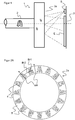
- FIG. 1 is a schematic representation of a basic structure of a position measuring device 1 in the form of a rotary encoder that detects a rotational angle position.
- the rotary encoder comprises a first object 2 in the form of a shaft, the position of which is to be determined in relation to a stationary second object 3 in the form of a circuit board.
- a measuring standard 2a is connected to the shaft, which rotates with the shaft with respect to the board and transmits modulated signals to a receiving unit E provided on the board in accordance with a rotation of the shaft.
- a reflective measuring arrangement of the position measuring device 1 is shown.
- the position measuring device 1 can, however, also be built on the transmitting measuring principle.
- a transmitter S is provided on the board, which in this exemplary embodiment emits an excitation light beam onto the measuring standard 2a, the excitation light beam being reflected back by the measuring standard 2a as the modulated signals.
- the material measure 2a is designed such that on the material measure 2a first and second signal-modulating elements 4 and 5, as on the Figures 2A and 2B shown, are arranged adjacent to one another.
- Each first and second element 4 and 5 has a respective orientation AR.
- the first elements 4 change in their circumference along their orientation AR in such a way that a ratio of a width between the width Br1 of the first element 4 and the width Br2 of the second element 5 along the orientation AR of the first or second element 4 or respectively 5 changed.
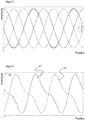
- the receiving unit E connected to the second object 3 generates a first and a second sine signal A1 and A2, as in FIG Figure 5 shown.
- the receiving unit E also generates first and second cosine signals B1 and B2, as in FIG Figure 5 shown.
- the position measuring device 1 comprises an evaluation unit, not shown, which evaluates the signals from the receiving unit E.
- the evaluation unit is designed such that the evaluation unit generates a first difference A1-B1, as in FIG Figure 6 shown, performs from the first sine signal A1 and the first cosine signal B1 to obtain a first difference signal ⁇ 1.
- the evaluation unit also performs a second difference formation A2-B2, as in FIG Figure 6 shown, from the second sine signal A2 and the second cosine signal B2 through to obtain a second difference signal ⁇ 2.
- the evaluation unit performs a summation ⁇ 1 + ⁇ 2, a third difference formation ⁇ 1- ⁇ 2, or a summation and third difference formation ⁇ 1 + ⁇ 2 and ⁇ 1- ⁇ 2 from the first and second difference signals ⁇ 1 and ⁇ 2.
- the evaluation unit compares a result of the summation ⁇ 1 + ⁇ 2, the third difference formation ⁇ 1- ⁇ 2, or the summation and third difference formation ⁇ 1 + ⁇ 2 and ⁇ 1- ⁇ 2 in order to determine a change in a duty cycle resulting from the changing ratio of the width. From this, the evaluation unit derives a position signal of the first object 2, which is dependent on this change in the duty cycle.
- the shape according to the invention of the measuring standard 2a causes a change in the duty cycle of the measuring standard 2a, so that the summation ⁇ 1 + ⁇ 2 and the differences in the signals A1, A2, B1 and B2 this change becomes visible and determinable.
- a position signal can be calculated without the influence of the eccentricity.
- the result of the summation ⁇ 1 + ⁇ 2 and / or the third difference formation ⁇ 1- ⁇ 2 can be compared with a reference position signal at an average duty cycle of 0.5 of the material measure 2a, so that an influence of the change in the duty cycle on the position signal can be determined even more precisely can.
- the erroneous influence of the eccentricity on the position signal can already be calculated from the summation ⁇ 1 + ⁇ 2 or the third difference formation ⁇ 1- ⁇ 2.
- the combination of the summation ⁇ 1 + ⁇ 2 and the third difference formation ⁇ 1- ⁇ 2 leads to an even more precise determination of the position signal, so that the position measuring device 1 can function even more precisely.
- the shape of the material measure 2a is preferably designed such that the second elements 5 change in their circumference along their orientation AR opposite to the first elements 4.
- the first elements 4 narrow along their alignment AR and the second elements 5 widen along their alignment AR.
- FIGS. 2A and 2 B each show preferred exemplary embodiments of a material measure 2a of the position measuring device 1 according to FIG Figure 1 , wherein in these exemplary embodiments the measuring standard 2a is designed in the form of a code disk.
- the first and second signal modulating elements 4 and 5 are aligned radially.
- the first element 4 has a frustoconical shape which is directed into the orientation AR of the first element 4.
- the area of the first element 4 decreases continuously.
- a width Br1 of the first element 4 decreases as the radius increases.
- the second signal-modulating elements 5 are arranged alternately adjacent to the first elements 4, each second element 5 likewise having a frusto-conical shape and being arranged in a radially directed manner.
- the area of every second element 5 increases opposite to the area of an adjacent first element 4 as the radius of the measuring standard 2a increases. In other words, the width Br2 of the second elements 5 increases as the radius of the material measure 2a increases.
- the duty cycle of the material measure 2a changes continuously between 0.0 and 1.0, in particular between 0.3 and 0.7, based on the alignment AR of the first and second elements 4 and 5, the duty cycle at the inner radius of the material measure 2a 0.0, in particular 0.3, and 1.0, in particular 0.7, at the outer radius.
- the signal-modulating first and second elements 4 and 5 also have a frusto-conical shape, the first and second elements 4 and 5 not, as with the first and second elements 4 and 5 the previous material measure 2a, are arranged exactly radially aligned.
- the first and second elements 4 and 5 are each arranged inclined to a radius of the material measure 2a.
- the arrangement of the first and second elements 4 and 5 has a saw blade-like shape in an overall view of the material measure 2a.
- the width Br1 of each first element 4 along its alignment AR continuously decreases with increasing radius of the measuring standard 2a and the width Br2 of each adjacent second element 5 increases in the opposite direction, with an increase in the width Br2 of the second elements 5 being greater than a decrease in the Width Br1 of the first elements 4 is, so that a change in the duty cycle of the measuring standard 2a of the Figure 2B from the change in the duty cycle of the measuring standard 2a Figure 2A differs.
- the evaluation unit can determine the eccentricity of the material measure 2a compared to the second on the basis of the characteristic change in the duty cycle Determine object 3 with the receiving unit E even more clearly and precisely.
- FIG. 3 a basic structure of another exemplary embodiment of the position measuring device 1 is shown schematically in the form of a linear displacement sensor.
- the displacement sensor consists of a movable first object 2 in the form of a scale with a measuring standard 2a, the first object 2 moving relative to a stationary second object 3.
- the mobility of the objects with respect to one another can also be provided in reverse as described.
- the first object 2 is arranged to be stationary and the second object 3 is arranged to be movable.
- the first object 2 can be the floor on which the measuring standard 2a is applied
- the second object 3 can be a sensor attached to a carriage, which moves with the carriage over the floor based on the detection of the measuring standard 2a determines the position of the car.
- a receiving unit E is arranged on the second object 3 and detects the measuring standard 2a.
- the material measure 2a has first and second signal-modulating elements 4 and 5, which are arranged alternately adjacent to one another on the measure 2a.
- the material measure 2a moves along a direction of movement B, shown as a double arrow, with respect to the first object 3.
- the first and second elements 4 and 5 also have a frusto-conical shape, the orientation AR of the first and second elements 4 and 5 being perpendicular to the direction of movement B of the material measure 2a is oriented. This changes a Duty cycle of the position measuring device 1 when the material measure 2a inclines or tilts with respect to the direction of movement B and thus with respect to the receiving unit E.
- the determination of the position of the scale or the material measure 2a remains precise due to the detection and consideration of the change in the duty cycle by the evaluation unit despite the possible inclination or tilting of the scale with respect to the receiving unit E.
- the width Br1 of the first elements 4 continuously decreases along the alignment AR, so that the effective area of the first elements 4 becomes smaller with increasing length along the alignment AR.
- the width Br2 of the second elements 5, on the other hand, increases continuously along the alignment AR, so that the effective area of the second elements 5 opposite to the first elements 4 increases with increasing length along the alignment AR.
- the change in the ratio of the width Br1 of the first elements 4 to the width Br2 of the second elements 5 causes the change in the duty cycle when the scale is inclined or tilted relative to the receiving unit E, this change being caused by the evaluation unit with the differences A1-B1 , A2-B2, the summation ⁇ 1 + ⁇ 2 and / or the difference formation ⁇ 1- ⁇ 2 is calculated.
- the receiving unit E includes photodetectors or magnetic sensors, depending on the embodiment.
- Photodetectors are a position measuring device 1 based on an optical measuring principle
- magnetic sensors are a position measuring device 1 based on a magnetic, capacitive or inductive measuring principle.
- the material measure 2a of an optical position measuring device 1 has light-permeable first signal-modulating elements 4 and light-impermeable second signal-modulating elements 5 or light-reflecting first elements 4 and light-absorbing second elements 5.
- an area of the first element 4 increases along the orientation AR and the area of the second element 5 decreases along the orientation AR.
- the first signal-modulating element 4 comprises a magnet and the second signal-modulating element 5 comprises a non-magnetic surface or the first element 4 comprises an electrode surface and the second element 5 comprises a non-electrifying surface.
- a magnetic field of the magnet or the electrode surface of the first element 4 decreases and the surface of the second element 5 increases in the opposite direction.
- the modulated signals of the measuring standard 2a are received by the receiving unit E and, as in FIG Figure 5 shown, recorded.
- the signals are called periodic oscillations in the Figure 5 reproduced, the first sine signal A1 being phase shifted by 90 ° with respect to the first cosine signal B1 and the second sine signal A2 being phase shifted by 90 ° with respect to the cosine signal B2.
- the first and second sine signals A1 and A2 or the first and second cosine signals B1 and B2 are phase-shifted by 180 ° with respect to one another.
- the evaluation unit of the position measuring device 1 forms a first difference signal ⁇ 1 from the first sine and cosine signals A1 and B1 and a second difference signal ⁇ 2 from the second sine and cosine signals A2 and B2.
- the course of the first and second difference signals ⁇ 1 and ⁇ 2 from the first and second difference formation is shown in FIG Figure 6 shown.
- This has the advantage that an offset of the individual phases of the signals is reduced. Furthermore, an influence of the change in the duty cycle due to the eccentricity of the material measure 2a can be seen from the curves. If the measuring standard 2a has moved by approximately one period of the signals A1, A2, B1 and B2, then the amplitude of the signals A1, A2, B1 and B2 can be determined. In addition, measured values of the signals A1, A2, B1 and B2 of at least half a period should be available so that the eccentricity of the material measure 2a can be clearly determined.
- the evaluation unit From the first and second difference signals ⁇ 1 and ⁇ 2, the evaluation unit performs a summation ⁇ 1 + ⁇ 2 and / or a third difference formation ⁇ 1- ⁇ 2.
- the results of the summation ⁇ 1 + ⁇ 2 and / or the third difference formation ⁇ 1- ⁇ 2 become compared with each other, so that the change in the duty cycle due to the changing ratio of the widths Br1 and Br2 of the first and second elements 4 and 5 is determined.
- the evaluation unit derives the position signals of the first object 2, in which the eccentricity of the material measure 2a is also taken into account.
- the evaluation unit preferably compares the results of the summation ⁇ 1 + ⁇ 2 and / or the third difference formation ⁇ 1- ⁇ 2 with values at an average duty cycle of 0.5 of the measuring standard, so that a positive or negative deviation of the duty cycle can be determined.
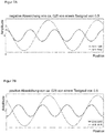
- the curves of the summation ⁇ 1 + ⁇ 2 with the negative and positive deviation have a phase shift of 180 ° with respect to one another, the curves of the third difference formation ⁇ 1- ⁇ 2 agreeing with one another.
- the curves of the summations ⁇ 1 + ⁇ 2 have a significantly higher amplitude compared to a curve (not shown) for the mean duty cycle of 0.5. This simplifies the derivation of the deviation of the position signals due to the eccentricity.
Landscapes
- Physics & Mathematics (AREA)
- General Physics & Mathematics (AREA)
- Engineering & Computer Science (AREA)
- Signal Processing (AREA)
- Length Measuring Devices With Unspecified Measuring Means (AREA)
- Transmission And Conversion Of Sensor Element Output (AREA)
Abstract
Description
- Die Erfindung betrifft eine Positionsmessvorrichtung zur Bestimmung einer Position eines ersten Objekts relativ zu einem gegenüber dem ersten Objekt beweglichen zweiten Objekt gemäß dem Anspruch 1.
- In vielfältigen Industrieanwendungen werden Sensoren als Positionsmessvorrichtungen eingesetzt, um eine Position eines ersten Objektes im Raum oder in Bezug zu einem stationären zweiten Objekt zu bestimmen. Hierbei können die Sensoren auf einem optischen, kapazitiven, induktiven oder magnetischen Messprinzip beruhen.
- Hierbei umfasst ein Sensor üblicherweise einen Sender, einen Modulator, einen Empfänger und eine Auswerteeinheit. Der Sender stellt einen Erregerstrahl bzw. eine Erregerwelle bereit, der bzw. die in Richtung des Modulators gerichtet ist. Der Modulator, der üblicherweise mit dem ersten Objekt verbunden ist und sich mit dem ersten Objekt bewegt, moduliert in Abhängigkeit von einer Bewegung des ersten Objektes einen ursprünglichen Zustand des Erregerstrahls bzw. der Erregerwelle. Der modulierte und geänderte Zustand des Erregerstrahls bzw. der Erregerwelle wird vom Empfänger detektiert und vorzugsweise in Cosinus- und Sinus-Signale für die Auswerteeinheit umgewandelt. Die Auswerteeinheit wertet die Cosinus- und Sinus-Signale aus und leitet daraus Positionssignale des ersten Objektes her.
- Um eine hochgenaue Bestimmung der Position des ersten Objektes zu gewährleisten, müssen der Sender, der Modulator und der Empfänger sehr genau zueinander im Sensor angeordnet werden, wobei eine sehr geringe Relativbewegung des Modulators gegenüber dem Empfänger, wie beispielsweise eine Exzentrizität des Modulators gegenüber dem Empfänger bei einem Drehgeber als Sensor, bereits zu einem nicht zu vernachlässigenden Messfehler bei der Bestimmung der Position des ersten Objektes führen kann.
- Es sind unterschiedliche Methoden bekannt, diesen Messfehler zu bestimmen und damit die Messgenauigkeit des Sensors bzw. der Positionsmessvorrichtung zu erhöhen.
- Eine Möglichkeit besteht beispielsweise darin, eine diametrale Messung insbesondere einer Winkelposition des ersten Objektes durchzuführen. Hierbei wird an zwei zu dem ersten Objekt bezogenen Positionen die Winkelposition bestimmt und dann ein Mittelwert und eine Positionsdifferenz gebildet. Daraus kann basierend auf einer Abweichung zwischen den zwei Winkelpositionswerten die Exzentrizität des ersten Objektes gegenüber dem zweiten Objekt ermittelt und in der Bestimmung der korrekten Position des ersten Objektes berücksichtigt werden.
- Eine weitere bekannte Möglichkeit zur Ermittlung der Exzentrizität des ersten Objektes besteht in einer Anordnung zusätzlicher Empfänger und insbesondere ein Vorsehen einer entsprechenden Codespur auf dem Modulator für den zusätzlichen Empfänger, so dass zusätzliche Messsignale der Position des ersten Objektes detektiert werden, die sich aufgrund der Exzentrizität unterscheiden. Hieraus kann die Exzentrizität direkt ermittelt werden. Mit der ermittelten Exzentrizität kann die aktuelle Position des ersten Objektes, beispielweise durch eine Umsetzungstabelle, korrigiert werden.
- Diese Vorgehensweisen weisen den Nachteil auf, dass zusätzliche Komponenten, insbesondere Abtastchips bzw. Empfänger oder Codespuren auf dem Modulator, verwendet werden müssen, wodurch die Komplexität des Sensors bzw. der Positionsmessvorrichtung erhöht wird. Demzufolge erhöht sich ebenfalls der Preis des Sensors bzw. der Positionsmessvorrichtung.
- Es ist eine Aufgabe der Erfindung, eine Positionsmessvorrichtung zur Bestimmung einer Position eines ersten Objekts relativ zu einem gegenüber dem ersten Objekt beweglichen zweiten Objekt zur Verfügung zu stellen, die eine verbesserte Messgenauigkeit gewährleistet.
- Die Aufgabe wird erfindungsgemäß durch eine Positionsmessvorrichtung mit den Merkmalen des Anspruchs 1 gelöst.
- Mit anderen Worten, die Positionsmessvorrichtung zur Bestimmung einer Position eines ersten Objektes relativ zu einem gegenüber dem ersten Objekt beweglichen zweiten Objekt umfasst eine mit dem ersten Objekt verbundene Maßverkörperung, die derart ausgebildet ist, dass auf der Maßverkörperung erste und zweite signalmodulierende Elemente benachbart zueinander angeordnet sind, wobei jedes erste und zweite Element eine jeweilige Ausrichtung aufweist, und die ersten Elemente entlang ihre Ausrichtung sich in ihrem Umfang derart verändern, dass sich ein Verhältnis einer Breite zwischen jeweils der Breite des ersten Elements und des zweiten Elements entlang der Ausrichtung des ersten bzw. zweiten Elements verändert. Ferner umfasst die Positionsmessvorrichtung eine mit dem zweiten Objekt verbundene Empfangseinheit, die ein erstes und ein zweites Sinus-Signal und ein erstes und ein zweites Cosinus-Signal erzeugt, und eine Auswerteeinheit zum Auswerten der Signale der Empfangseinheit. Die Auswerteeinheit ist ausgelegt, eine erste Differenzenbildung aus dem ersten Sinus-Signal und dem ersten Cosinus-Signal zum Erhalt eines ersten Differenzsignals und eine zweite Differenzenbildung aus dem zweiten Sinus-Signal und dem zweiten Cosinus-Signal zum Erhalt eines zweiten Differenzsignals durchzuführen. Die Auswerteeinheit führt ferner eine Summen- und/oder eine dritte Differenzenbildung aus dem ersten und zweiten Differenzsignal durch und vergleicht ein Ergebnis der Summen- und/oder der dritten Differenzenbildung, um eine Änderung eines aufgrund des verändernden Verhältnisses der Breite resultierenden Tastgrades zu ermitteln und ein von der Änderung des Tastgrades abhängiges Positionssignal abzuleiten.
- Hierdurch ergibt sich der Vorteil, dass die Positionsmessvorrichtung mit beispielsweise nur einem Abtastchip bzw. einer Empfangseinheit ausgestattet werden muss, um eine hochgenaue Positionsbestimmung zu gewährleisten. Ferner kann eine bestehende Positionsmessvorrichtung mit der erfindungsgemäßen Auswerteeinheit nachträglich ausgerüstet werden, so dass die Messgenauigkeit einer bestehenden Positionsmessvorrichtung verbessert werden kann.
- In diesem Zusammenhang wird unter Tastgrad ein Verhältnis zwischen der Impulsdauer zur Periodendauer einer periodischen Folge von Signalimpulsen verstanden. Das heißt, bei einem Tastgrad von 0,5 ergibt sich eine Folge aus symmetrischen Signalimpulsen. Je mehr der Tastgrad von dem Wert 0,5 abweicht, desto unsymmetrischer werden die Signalimpulse der Folge.
- Gemäß einem bevorzugten Ausführungsbeispiel verändern sich die zweiten Elemente entlang ihre Ausrichtung entgegengesetzt zu den ersten Elementen in ihrem Umfang, wobei sich die ersten Elemente entlang ihrer Ausrichtung verschlanken und sich die zweiten Elemente entlang ihrer Ausrichtung verbreitern. Hierbei ist unter Verschlanken bzw. Verbreitern zu verstehen, dass eine Breite eines jeweiligen ersten bzw. zweiten Elements entlang ihrer Ausrichtung kontinuierlich abnimmt bzw. zunimmt, so dass eine Fläche des ersten bzw. zweiten Elements insgesamt kleiner bzw. größer wird.
- Gemäß einem weiteren bevorzugten Ausführungsbeispiel sind das erste Objekt eine Welle und die Maßverkörperung eine Codescheibe oder das erste Objekt eine Schiene und die Maßverkörperung ein linearer Maßstab. Das heißt, dass eine Bestimmung sowohl einer Winkelposition als auch einer linearen Position exakt möglich ist, da ein Messfehler aufgrund einer Exzentrizität ermittelt und berücksichtigt werden kann.
- Weiterhin ist gemäß einem weiteren bevorzugten Ausführungsbeispiel bei einer Codescheibe die Ausrichtung der ersten und zweiten Elemente radial gerichtet oder bei einem linearen Maßstab die Ausrichtung der ersten und zweiten Elemente senkrecht zu einer Bewegungsrichtung des Maßstabs gerichtet. Hierdurch ist es vorteilhafterweise möglich, eine negative oder positive Abweichung des Tastgrades von einem Tastgrad von 0,5 zu detektieren.
- Vorteilhafterweise umfasst die Empfangseinheit Fotodetektoren oder Magnetsensoren, so dass die Positionsmessvorrichtung insbesondere auf einem optischen, magnetischen, kapazitiven oder induktiven Messprinzip aufgebaut werden kann. Hierbei sind insbesondere das erste signalmodulierende Element lichtdurchlässig und das zweite signalmodulierende Element lichtundurchlässig oder das erste Element lichtreflektierend und das zweite Element lichtabsorbierend, wobei vorzugsweise sich eine Fläche des ersten Elements entlang der Ausrichtung vergrößert und sich die Fläche des zweiten signalmodulierenden Elements entgegengesetzt verkleinert.
- Andererseits umfassen vorteilhafterweise das erste signalmodulierende Element einen Magnet und das zweite Element eine nicht magnetische Fläche oder das erste Element eine Elektrodenfläche und das zweite Element eine nicht elektrisierende Fläche, wobei insbesondere ein Magnetfeld des Magneten oder der Elektrodenfläche entlang der Ausrichtung abnimmt und sich die Fläche des zweiten Elements entgegengesetzt vergrößert.
- Weiterhin verändert sich, gemäß einem weiteren bevorzugten Ausführungsbeispiel, der Tastgrad der Maßverkörperung bezogen auf die Ausrichtung der ersten und zweiten Elemente kontinuierlich zwischen 0 und 1, insbesondere 0,3 und 0,7, so dass die Exzentrizität der Maßverkörperung am ersten Objekt genau bestimmt werden kann. Hierbei sind vorzugsweise das erste Sinus-Signal um 90° phasenversetzt zu dem ersten Cosinus-Signal und das zweite Sinus-Signal um 90° phasenversetzt zu dem zweiten Cosinus-Signal. Insbesondere sind das zweite Cosinus-Signal um 180° phasenversetzt zu dem ersten Cosinus-Signal und das zweite Sinus-Signal um 180° phasenversetzt zu dem ersten Sinus-Signal.
- Dadurch ist eine eindeutige Unterscheidung zwischen den Signalen gegeben, die zu einem auswertbaren Signalverlauf aus der Summen- und/oder dritten Differenzenbildung führt.
- Zusätzlich ist die Auswerteeinheit vorzugsweise ausgelegt, die ermittelten Werte des resultierenden Tastgrades mit Werten bei einem mittleren Tastgrad von 0,5 der Maßverkörperung zu vergleichen, so dass eine positive oder negative Abweichung des Tastgrades bestimmbar ist.
- Die erfindungsgemäße Positionsmessvorrichtung kann auf ähnliche Weise durch weitere Merkmale ausgestaltet werden und zeigt dabei ähnliche Vorteile. Derartige weitere Merkmale sind beispielhaft, aber nicht abschließend in den sich an den unabhängigen Anspruch anschließenden Unteransprüchen beschrieben.
- Die Erfindung wird nachstehend auch hinsichtlich weiterer Vorteile und Merkmale unter Bezugnahme auf die beigefügten Zeichnungen anhand von Ausführungsbeispiele erläutert. Die Figur der Zeichnungen zeigt in:
- Fig. 1
- eine schematische Darstellung eines Grundaufbaus einer Positionsmessvorrichtung in Form eines Drehgebers,
- Fig. 2A
- eine schematische Darstellung eines ersten Ausführungsbeispiels einer erfindungsgemäßen Maßverkörperung der Positionsmessvorrichtung in der Figur 1,
- Fig. 2B
- eine schematische Darstellung eines zweiten Ausführungsbeispiels der Maßverkörperung der Positionsmessvorrichtung in der
Figur 1 , - Fig. 3
- eine schematische Darstellung eines Grundaufbaus der Positionsmessvorrichtung in Form eines linearen Wegsensors,
- Fig. 4
- eine schematische Darstellung eines Ausführungsbeispiels eines erfindungsgemäßen Maßstabs der Positionsmessvorrichtung in der
Figur 3 , - Fig. 5
- eine schematische Darstellung der Verläufe der Signale der Empfangseinheit der Positionsmessvorrichtung ohne eine Abweichung vom Tastgrad 0,5,
- Fig. 6
- eine schematische Darstellung der Verläufe der ersten und zweiten Differenzsignale bei einer Abweichung vom Tastgrad 0,5 von 0,25, und
- Fig. 7A,
- 7B eine schematische Darstellung der Verläufe der Summen- und dritten Differenzenbildung bei einer negativen bzw. positiven Abweichung vom Tastgrad von 0,5.
- In der
Figur 1 ist eine schematische Darstellung eines Grundaufbaus einer Positionsmessvorrichtung 1 in Form eines Drehgebers dargestellt, der eine Drehwinkelposition erfasst. Der Drehgeber umfasst ein erstes Objekt 2 in Form einer Welle, dessen Position gegenüber eines stationären zweiten Objektes 3 in Form einer Platine bestimmt werden soll. Mit der Welle ist eine Maßverkörperung 2a verbunden, die sich mit der Welle gegenüber der Platine dreht und entsprechend einer Drehung der Welle modulierte Signale an eine auf der Platine vorgesehene Empfangseinheit E übermittelt. Beim dem dargestellten Ausführungsbeispiel ist eine reflexive Messanordnung der Positionsmessvorrichtung 1 gezeigt. Die Positionsmessvorrichtung 1 kann jedoch auch auf dem transmittierenden Messprinzip aufgebaut sein. - Hierbei ist auf der Platine ein Sender S vorgesehen, der in diesem Ausführungsbeispiel einen Erregerlichtstrahl auf die Maßverkörperung 2a aussendet, wobei der Erregerlichtstrahl von der Maßverkörperung 2a als die modulierten Signale zurückreflektiert wird. Erfindungsgemäß ist die Maßverkörperung 2a derart ausgebildet, dass auf der Maßverkörperung 2a erste und zweite signalmodulierende Elemente 4 und 5, wie auf den
Figuren 2A und 2B dargestellt, benachbart zueinander angeordnet sind. Jedes erste und zweite Element 4 und 5 weist eine jeweilige Ausrichtung AR auf. Die ersten Elemente 4 verändern sich entlang ihre Ausrichtung AR in ihrem Umfang derart, dass sich ein Verhältnis einer Breite zwischen jeweils der Breite Br1 des ersten Elements 4 und der Breite Br2 des zweiten Elements 5 entlang der Ausrichtung AR des ersten bzw. zweiten Elements 4 bzw. 5 verändert. - Die mit dem zweiten Objekt 3 verbundene Empfangseinheit E erzeugt ein erstes und ein zweites Sinus-Signal A1 und A2, wie in der
Figur 5 dargestellt. Die Empfangseinheit E erzeugt ferner ein erstes und zweites Cosinus-Signal B1 und B2, wie in derFigur 5 dargestellt. - Die Positionsmessvorrichtung 1 umfasst eine nicht dargestellte Auswerteeinheit, die die Signale der Empfangseinheit E auswertet. Hierbei ist die Auswerteeinheit derart ausgelegt, dass die Auswerteeinheit eine erste Differenzenbildung A1-B1, wie in der
Figur 6 dargestellt, aus dem ersten Sinus-Signal A1 und dem ersten Cosinus-Signal B1 durchführt, um ein erstes Differenzsignal Δ1 zu erhalten. Die Auswerteeinheit führt weiterhin eine zweite Differenzenbildung A2-B2, wie in derFigur 6 dargestellt, aus dem zweiten Sinus-Signal A2 und dem zweiten Cosinus-Signal B2 durch, um ein zweites Differenzsignal Δ2 zu erhalten. - Weiterhin führt die Auswerteeinheit eine Summenbildung Δ1+Δ2, eine dritte Differenzenbildung Δ1-Δ2, oder eine Summen- und dritte Differenzenbildung Δ1+Δ2 und Δ1-Δ2 aus dem ersten und zweiten Differenzsignal Δ1 und Δ2 durch. Die Auswerteeinheit vergleicht ein Ergebnis der Summenbildung Δ1+Δ2, der dritten Differenzenbildung Δ1-Δ2, oder der Summen- und dritten Differenzenbildung Δ1+Δ2 und Δ1-Δ2 um eine Änderung eines aufgrund des verändernden Verhältnisses der Breite resultierenden Tastgrades zu ermitteln. Hieraus leitet die Auswerteeinheit ein Positionssignal des ersten Objektes 2 ab, das von dieser Änderung des Tastgrades abhängig ist.
- Mit anderen Worten, bei einem Vorhandensein einer Exzentrizität zwischen der Maßverkörperung und der Empfangseinheit E, bewirkt die erfindungsgemäße Form der Maßverkörperung 2a eine Änderung des Tastgrades der Maßverkörperung 2a, so dass durch die Summenbildung Δ1+Δ2 und die Differenzenbildungen der Signale A1, A2, B1 und B2 diese Änderung ersichtlich und bestimmbar wird. Mittels eines Vergleichs des Ergebnisses der Summenbildung Δ1+Δ2 und/oder der dritten Differenzenbildung Δ1-Δ2 kann ein Positionssignal ohne den Einfluss der Exzentrizität errechnet werden. Insbesondere kann das Ergebnis der Summenbildung Δ1+Δ2 und/oder der dritten Differenzenbildung Δ1-Δ2 mit einem Bezugspositionssignal bei einem mittleren Tastgrad von 0,5 der Maßverkörperung 2a verglichen werden, so dass ein Einfluss der Änderung des Tastgrades auf das Positionssignal noch genauer bestimmt werden kann.
- Aus der Summenbildung Δ1+Δ2 oder der dritten Differenzenbildung Δ1-Δ2 ist bereits der fehlerhafte Einfluss der Exzentrizität auf das Positionssignal errechenbar. Die Kombination aus der Summenbildung Δ1+Δ2 und der dritten Differenzenbildung Δ1-Δ2 führt zu einer noch präziseren Bestimmung des Positionssignals, so dass die Positionsmessvorrichtung 1 noch präziser funktionieren kann.
- Die Form der Maßverkörperung 2a ist vorzugsweise derart ausgebildet, dass sich die zweiten Elemente 5 entlang ihrer Ausrichtung AR entgegengesetzt zu den ersten Elementen 4 in ihrem Umfang verändern. Insbesondere verschlanken sich die ersten Elemente 4 entlang ihrer Ausrichtung AR und verbreitern sich die zweiten Elemente 5 entlang ihrer Ausrichtung AR.
- Die
Figuren 2A und2B zeigen jeweils bevorzugte Ausführungsbeispiele einer Maßverkörperung 2a der Positionsmessvorrichtung 1 gemäß derFigur 1 , wobei in diesen Ausführungsbeispielen die Maßverkörperung 2a in Form einer Codescheibe ausgebildet ist. - Bei der Maßverkörperung 2a bzw. Codescheibe in der
Figur 2A sind die ersten und zweiten signalmodulierenden Elemente 4 und 5 radial ausgerichtet. Das erste Element 4 weist eine stumpf-kegelförmige Form auf, die in die Ausrichtung AR des ersten Elements 4 gerichtet ist. Mit zunehmendem Radius der Maßverkörperung 2a nimmt die Fläche des ersten Elements 4 kontinuierlich ab. Mit anderen Worten eine Breite Br1 des ersten Elements 4 nimmt mit zunehmendem Radius ab. - Die zweiten signalmodulierenden Elemente 5 sind abwechselnd benachbart zu den ersten Elementen 4 angeordnet, wobei jedes zweite Element 5 ebenfalls eine stumpf-kegelförmige Form aufweist und radial gerichtet angeordnet ist. Die Fläche jedes zweiten Elements 5 nimmt entgegengesetzt zu der Fläche eines benachbarten ersten Elements 4 mit zunehmendem Radius der Maßverkörperung 2a zu. Das heißt mit anderen Worten, die Breite Br2 der zweiten Elemente 5 nimmt mit zunehmendem Radius der Maßverkörperung 2a zu.
- Hierdurch verändert sich vorzugsweise der Tastgrad der Maßverkörperung 2a bezogen auf die Ausrichtung AR der ersten und zweiten Elemente 4 und 5 kontinuierlich zwischen 0,0 und 1,0, insbesondere zwischen 0,3 und 0,7, wobei der Tastgrad am Innenradius der Maßverkörperung 2a 0,0, insbesondere 0,3, und am Außenradius 1,0, insbesondere 0,7, beträgt.
- Bei dem weiteren bevorzugten Ausführungsbeispiel der Maßverkörperung 2a in der Figur 2B weisen die signalmodulierenden ersten und zweiten Elemente 4 und 5 ebenfalls eine stumpf-kegelförmige Form, wobei die ersten und zweiten Elemente 4 und 5 nicht, wie bei den ersten und zweiten Elemente 4 und 5 der vorherigen Maßverkörperung 2a, exakt radial ausgerichtet angeordnet sind. Die ersten und zweiten Elemente 4 und 5 sind jeweils geneigt zu einem Radius der Maßverkörperung 2a angeordnet.
- Die Anordnung der ersten und zweiten Elemente 4 und 5 weist in einer Gesamtbetrachtung der Maßverkörperung 2a ein Sägeblatt ähnliche Form auf.
- Hierbei nehmen die Breite Br1 eines jeden ersten Elements 4 entlang dessen Ausrichtung AR mit zunehmendem Radius der Maßverkörperung 2a kontinuierlich ab und die Breite Br2 eines jeden benachbarten zweiten Elements 5 entgegengesetzt zu, wobei eine Zunahme der Breite Br2 der zweiten Elemente 5 größer als eine Abnahme der Breite Br1 der ersten Elemente 4 ist, so dass eine Änderung des Tastgrades der Maßverkörperung 2a der
Figur 2B sich von der Änderung des Tastgrades der Maßverkörperung 2a derFigur 2A unterscheidet. - Mittels der zusätzlichen Neigung der ersten und zweiten Elemente 4 und 5 gegenüber dem Radius der Maßverkörperung 2a und der unterschiedlichen Ab- bzw. Zunahme der Breite Br1 bzw. Br2 kann die Auswerteeinheit auf Basis der charakteristischen Änderung des Tastgrades die Exzentrizität der Maßverkörperung 2a gegenüber dem zweiten Objekt 3 mit der Empfangseinheit E noch eindeutiger und genauer bestimmen.
- In der
Figur 3 ist schematisch ein Grundaufbau eines anderen Ausführungsbeispiels der Positionsmessvorrichtung 1 in Form eines linearen Wegsensors dargestellt. Der Wegsensor besteht aus einem beweglichen ersten Objekt 2 in Form eines Maßstabs mit einer Maßverkörperung 2a, wobei sich das erste Objekt 2 gegenüber einem stationären zweiten Objekt 3 bewegt. - In diesem Zusammenhang sei erwähnt, dass die Beweglichkeit der Objekte zueinander auch umgekehrt wie beschrieben vorgesehen sein kann. Das heißt, dass das erste Objekt 2 stationär und das zweite Objekt 3 beweglich angeordnet sind. In diesem Ausführungsbeispiel können beispielsweise das erste Objekt 2 der Boden sein, auf dem die Maßverkörperung 2a aufgebracht ist, und das zweite Objekt 3 einen an einem Wagen befestigten Sensor sein, der sich mit dem Wagen über den Boden hinwegbewegt und dabei anhand der Erfassung der Maßverkörperung 2a die Position des Wagens ermittelt.
- An dem zweiten Objekt 3 ist eine Empfangseinheit E angeordnet, die die Maßverkörperung 2a erfasst.
- Wie in der
Figur 4 als schematische Draufsicht auf die Maßverkörperung 2a bzw. auf den Maßstab dargestellt, weist die Maßverkörperung 2a erste und zweite signalmodulierende Elemente 4 und 5 auf, die abwechselnd benachbart zueinander auf der Maßverkörperung 2a angeordnet sind. Die Maßverkörperung 2a bewegt sich entlang einer als Doppelpfeil dargestellten Bewegungsrichtung B gegenüber dem ersten Objekt 3. - Die ersten und zweiten Elemente 4 und 5 weisen, wie bei den vorher beschriebenen Elementen 4 und 5 der Codescheibe, ebenfalls eine stumpf-kegelförmige Form auf, wobei die Ausrichtung AR der ersten und zweiten Elemente 4 und 5 senkrecht zu der Bewegungsrichtung B der Maßverkörperung 2a orientiert ist. Hierdurch verändert sich ein Tastgrad der Positionsmessvorrichtung 1, wenn sich die Maßverkörperung 2a gegenüber der Bewegungsrichtung B und damit gegenüber der Empfangseinheit E neigt bzw. kippt.
- Die Bestimmung der Position des Maßstabs bzw. der Maßverkörperung 2a bleibt durch die Erfassung und Berücksichtigung der Änderung des Tastgrades durch die Auswerteinheit trotz der möglichen Neigung bzw. Kippung des Maßstabs gegenüber der Empfangseinheit E präzise.
- Die Breite Br1 der ersten Elemente 4 nimmt entlang der Ausrichtung AR kontinuierlich ab, so dass die effektive Fläche der ersten Elemente 4 mit zunehmender Länge entlang der Ausrichtung AR kleiner wird. Die Breite Br2 der zweiten Elemente 5 nimmt hingegen entlang der Ausrichtung AR kontinuierlich zu, so dass die effektive Fläche der zweiten Elemente 5 entgegengesetzt zu den ersten Elementen 4 mit zunehmender Länge entlang der Ausrichtung AR größer wird.
- Die Änderung des Verhältnisses der Breite Br1 der ersten Elemente 4 zu der Breite Br2 der zweiten Elemente 5 bewirkt die Änderung des Tastgrades bei Vorhandensein der Neigung bzw. Kippung des Maßstabs gegenüber der Empfangseinheit E, wobei diese Änderung durch die Auswerteeinheit mit den Differenzenbildungen A1-B1, A2-B2, der Summenbildung Δ1+Δ2 und/oder der Differenzenbildung Δ1-Δ2 errechnet wird.
- Die Empfangseinheit E umfasst je nach Ausführungsbeispiel Fotodetektoren oder Magnetsensoren. Bei Fotodetektoren handelt es sich um eine auf optischem Messprinzip basierende Positionsmessvorrichtung 1 und bei Magnetsensoren handelt es sich um eine auf magnetischem, kapazitivem oder induktivem Messprinzip basierende Positionsmessvorrichtung 1.
- Die Maßverkörperung 2a einer optischen Positionsmessvorrichtung 1 weist lichtdurchlässige erste signalmodulierende Elemente 4 und lichtundurchlässige zweite signalmodulierende Elemente 5 oder lichtreflektierende erste Elemente 4 und lichtabsorbierende zweite Elemente 5 auf. Insbesondere vergrößert sich eine Fläche des ersten Elements 4 entlang der Ausrichtung AR und verkleinert sich die Fläche des zweiten Elements 5 entlang der Ausrichtung AR.
- Bei einer auf magnetischem, kapazitivem oder induktivem Messprinzip basierenden Positionsmessvorrichtung 1 umfasst das erste signalmodulierende Element 4 einen Magnet und das zweite signalmodulierende Element 5 eine nicht magnetische Fläche oder das erste Element 4 eine Elektrodenfläche und das zweite Element 5 eine nicht elektrisierende Fläche. Hierbei nimmt insbesondere ein Magnetfeld des Magneten oder der Elektrodenfläche des ersten Elements 4 ab und sich die Fläche des zweiten Elements 5 entgegengesetzt vergrößert.
- Die modulierten Signale der Maßverkörperung 2a werden von der Empfangseinheit E empfangen und, wie in der
Figur 5 dargestellt, erfasst. Die Signale werden als periodische Schwingungen in derFigur 5 wiedergegeben, wobei das erste Sinus-Signal A1 um 90° phasenversetzt zu dem ersten Cosinus-Signal B1 und das zweite Sinus-Signal A2 um 90° phasenversetzt zu dem Cosinus-Signal B2 sind. Vor allem sind das erste und zweite Sinus-Signal A1 und A2 bzw. das erste und zweite Cosinus-Signal B1 und B2 um 180° zueinander phasenversetzt. - Die Auswerteeinheit der erfindungsgemäßen Positionsmessvorrichtung 1 bildet aus den ersten Sinus- und Cosinus-Signal A1 und B1 ein erstes Differenzensignal Δ1 und aus den zweiten Sinus- und Cosinus-Signal A2 und B2 ein zweites Differenzensignal Δ2. Der Verlauf der ersten und zweiten Differenzensignale Δ1 und Δ2 aus der ersten und zweiten Differenzenbildung ist in der
Figur 6 dargestellt. Hieraus ergibt sich der Vorteil, dass ein Offset der Einzelphasen der Signale reduziert wird. Ferner ist aus den Kurven ein Einfluss der Änderung des Tastgrades aufgrund der Exzentrizität der Maßverkörperung 2a sichtbar. Wenn sich die Maßverkörperung 2a um ca. eine Periode der Signale A1, A2, B1 und B2 bewegt hat, dann sind die Amplitude der Signale A1, A2, B1 und B2 ermittelbar. Zusätzlich sollten Messwerte der Signale A1, A2, B1 und B2 von mindestens einer halben Periode vorhanden sein, damit eine eindeutige Ermittlung der Exzentrizität der Maßverkörperung 2a durchführbar ist. - Aus den ersten und zweiten Differenzensignale Δ1 und Δ2 führt die Auswerteeinheit eine Summenbildung Δ1+Δ2 und/oder eine dritte Differenzenbildung Δ1-Δ2 durch. Die Ergebnisse der Summenbildung Δ1+Δ2 und/oder der dritten Differenzenbildung Δ1-Δ2 werden miteinander verglichen, so dass die Änderung des Tastgrades aufgrund des verändernden Verhältnisses der Breite Br1 und Br2 der ersten und zweiten Elemente 4 und 5 ermittelt wird. In Abhängigkeit von dieser Änderung des Tastgrades leitet die Auswerteeinheit die Positionssignale des ersten Objektes 2 ab, bei denen die Exzentrizität der Maßverkörperung 2a mitberücksichtigt ist.
- Ferner vergleicht die Auswerteeinheit vorzugsweise die Ergebnisse der Summenbildung Δ1+Δ2 und/oder der dritten Differenzenbildung Δ1-Δ2 mit Werten bei einem mittleren Tastgrad von 0,5 der Maßverkörperung, so dass eine positive oder negative Abweichung des Tastgrades bestimmbar ist.
- In den
Figuren 7A und 7B ist beispielshaft jeweils das Ergebnis der Summenbildung Δ1+Δ2 und der dritten Differenzenbildung Δ1-Δ2 bezogen auf ein Tastgrad von 0,5 grafisch dargestellt, wobei in derFigur 7A die Abweichung um -0,25 von dem Tastgrad von 0,5 und in derFigur 7B die Abweichung um +0,25 von dem Tastgrad von 0,5 beträgt. - Die Kurven der Summenbildungen Δ1+Δ2 mit der negativen und positiven Abweichung weisen eine Phasenverschiebung von 180° zueinander auf, wobei die Kurven der dritten Differenzenbildung Δ1-Δ2 miteinander übereinstimmen. Zusätzlich weisen die Kurven der Summenbildungen Δ1+Δ2 eine wesentlich höhere Amplitude gegenüber einer nicht dargestellten Kurve für den mittleren Tastgrad von 0,5 auf. Hierdurch ist das Ableiten der Abweichung der Positionssignale aufgrund der Exzentrizität vereinfacht.
-
- 1
- Positionsmessvorrichtung
- 2
- Erstes Objekt
- 2a
- Maßverkörperung
- 3
- Zweites Objekt
- 4
- Erstes signalmodulierende Element
- 5
- Zweites signalmodulierende Element
- AR
- Ausrichtung
- B
- Bewegungsrichtung
- Br1, Br2
- Breite des ersten und zweiten Elements
- E
- Empfangseinheit
- S
- Sender
Claims (13)
- Positionsmessvorrichtung (1) zur Bestimmung einer Position eines ersten Objekts (2) relativ zu einem gegenüber dem ersten Objekt (2) beweglichen zweiten Objekt (3), umfassend:- eine mit dem ersten Objekt (2) verbundene Maßverkörperung (2a), die derart ausgebildet ist, dass auf der Maßverkörperung (2a) erste und zweite signalmodulierende Elemente (4, 5) benachbart zueinander angeordnet sind, wobei jedes erste und zweite Element (4, 5) eine jeweilige Ausrichtung (AR) aufweist, und die ersten Elemente (4) entlang ihre Ausrichtung (AR) sich in ihrem Umfang derart verändern, dass sich ein Verhältnis einer Breite (Br1, Br2) zwischen jeweils der Breite des ersten Elements (4) und des zweiten Elements (5) entlang der Ausrichtung (AR) des ersten bzw. zweiten Elements (4, 5) verändert,- eine mit dem zweiten Objekt (3) verbundene Empfangseinheit (E), die ein erstes und ein zweites Sinus-Signal (A1, A2) und ein erstes und ein zweites Cosinus-Signal (B1, B2) erzeugt, und- eine Auswerteeinheit zum Auswerten der Signale der Empfangseinheit (E), wobei die Auswerteeinheit ausgelegt ist:eine erste Differenzenbildung aus dem ersten Sinus-Signal und dem ersten Cosinus-Signal zum Erhalt eines ersten Differenzsignals (Δ1) und eine zweite Differenzenbildung aus dem zweiten Sinus-Signal und dem zweiten Cosinus-Signal zum Erhalt eines zweiten Differenzsignals (Δ2) durchzuführen,eine Summen- und/oder eine dritte Differenzenbildung (Δ1+Δ2, Δ1-Δ2) aus dem ersten und zweiten Differenzsignal (Δ1, Δ2) durchzuführen, undein Ergebnis der Summen- und/oder der dritten Differenzenbildung (Δ1+Δ2, Δ1-Δ2) zu vergleichen, um eine Änderung eines aufgrund des verändernden Verhältnisses der Breite (Br1, Br2) resultierenden Tastgrades zu ermitteln und ein von der Änderung des Tastgrades abhängiges Positionssignal abzuleiten.
- Positionsmessvorrichtung (1) nach Anspruch 1, wobei sich die zweiten Elemente (5) entlang ihrer Ausrichtung (AR) entgegengesetzt zu den ersten Elementen (4) in ihrem Umfang verändern, und wobei die ersten Elemente (4) sich entlang ihrer Ausrichtung (AR) verschlanken und die zweiten Elemente (5) sich entlang ihrer Ausrichtung (AR) verbreitern.
- Positionsmessvorrichtung (1) nach Anspruch 1 oder 2, wobei das erste Objekt (2) eine Welle und die Maßverkörperung (2a) eine Codescheibe sind oder das erste Objekt (2) eine Schiene und die Maßverkörperung (2a) ein linearer Maßstab sind.
- Positionsmessvorrichtung (1) nach Anspruch 3, wobei bei einer Codescheibe die Ausrichtung (AR) der ersten und zweiten Elemente (4, 5) radial gerichtet ist oder bei einem linearen Maßstab die Ausrichtung (AR) der ersten und zweiten Elemente (4, 5) senkrecht zu einer Bewegungsrichtung (B) des Maßstabs gerichtet ist.
- Positionsmessvorrichtung (1) nach einem der vorhergehenden Ansprüche 1 bis 4, wobei die Empfangseinheit (E) Fotodetektoren oder Magnetsensoren umfasst.
- Positionsmessvorrichtung (1) nach einem der vorhergehenden Ansprüche 1 bis 5, wobei das erste signalmodulierende Element (4) lichtdurchlässig und das zweite signalmodulierende Element (5) lichtundurchlässig oder das erste Element (4) lichtreflektierend und das zweite Element (5) lichtabsorbierend sind.
- Positionsmessvorrichtung (1) nach Anspruch 6, wobei sich eine Fläche des ersten Elements (4) entlang der Ausrichtung vergrößert und sich die Fläche des zweiten signalmodulierenden Elements (5) entgegengesetzt verkleinert.
- Positionsmessvorrichtung (1) nach einem der Ansprüche 1 bis 5, wobei das erste signalmodulierende Element (4) einen Magnet und das zweite Element (5) eine nicht magnetische Fläche oder das erste Element (4) eine Elektrodenfläche und das zweite Element (5) eine nicht elektrisierende Fläche umfassen.
- Positionsmessvorrichtung (1) nach Anspruch 8, wobei ein Magnetfeld des Magneten oder der Elektrodenfläche entlang der Ausrichtung (AR) abnimmt und sich die Fläche des zweiten Elements entgegengesetzt vergrößert.
- Positionsmessvorrichtung (1) nach einem der Ansprüche 1 bis 9, wobei sich der Tastgrad der Maßverkörperung (2a) bezogen auf die Ausrichtung (AR) der ersten und zweiten Elemente (4, 5) zwischen 0 und 1, insbesondere 0,3 und 0,7, kontinuierlich verändert.
- Positionsmessvorrichtung (1) nach einem der Ansprüche 1 bis 10, wobei das erste Sinus-Signal um 90° phasenversetzt zu dem ersten Cosinus-Signal und das zweite Sinus-Signal um 90° phasenversetzt zu dem zweiten Cosinus-Signal sind.
- Positionsmessvorrichtung (1) nach Anspruch 11, wobei das zweite Cosinus-Signal um 180° phasenversetzt zu dem ersten Cosinus-Signal und das zweite Sinus-Signal um 180° phasenversetzt zu dem ersten Sinus-Signal sind.
- Positionsmessvorrichtung (1) nach einem der Ansprüche 1 bis 12, wobei die Auswerteeinheit ausgelegt ist, die ermittelten Werte des resultierenden Tastgrades mit Werten bei einem mittleren Tastgrad von 0,5 der Maßverkörperung zu vergleichen, so dass eine positive oder negative Abweichung des Tastgrades bestimmbar ist.
Priority Applications (1)
| Application Number | Priority Date | Filing Date | Title |
|---|---|---|---|
| EP19204435.2A EP3812709B1 (de) | 2019-10-21 | 2019-10-21 | Positionsmessvorrichtung |
Applications Claiming Priority (1)
| Application Number | Priority Date | Filing Date | Title |
|---|---|---|---|
| EP19204435.2A EP3812709B1 (de) | 2019-10-21 | 2019-10-21 | Positionsmessvorrichtung |
Publications (2)
| Publication Number | Publication Date |
|---|---|
| EP3812709A1 true EP3812709A1 (de) | 2021-04-28 |
| EP3812709B1 EP3812709B1 (de) | 2021-08-04 |
Family
ID=68392705
Family Applications (1)
| Application Number | Title | Priority Date | Filing Date |
|---|---|---|---|
| EP19204435.2A Active EP3812709B1 (de) | 2019-10-21 | 2019-10-21 | Positionsmessvorrichtung |
Country Status (1)
| Country | Link |
|---|---|
| EP (1) | EP3812709B1 (de) |
Citations (5)
| Publication number | Priority date | Publication date | Assignee | Title |
|---|---|---|---|---|
| DE4402401A1 (de) * | 1994-01-27 | 1995-08-03 | Heidenhain Gmbh Dr Johannes | Winkelmeßeinrichtung mit mehreren Abtaststellen |
| JP2005024493A (ja) * | 2003-07-02 | 2005-01-27 | Nissan Motor Co Ltd | レゾルバの異常検出装置 |
| US20090206827A1 (en) * | 2006-11-21 | 2009-08-20 | Hitachi Metals, Ltd. | Rotation-angle-detecting apparatus, rotating machine, and rotation-angle-detecting method |
| EP2466266A2 (de) * | 2010-12-15 | 2012-06-20 | Canon Kabushiki Kaisha | Absolutdrehcodierer |
| EP3451526A1 (de) * | 2016-04-28 | 2019-03-06 | Mitsubishi Electric Corporation | Fehlerbestimmungsvorrichtung für eine steuerungsvorrichtung einer rotierenden maschine und fehlerbestimmungsverfahren |
-
2019
- 2019-10-21 EP EP19204435.2A patent/EP3812709B1/de active Active
Patent Citations (5)
| Publication number | Priority date | Publication date | Assignee | Title |
|---|---|---|---|---|
| DE4402401A1 (de) * | 1994-01-27 | 1995-08-03 | Heidenhain Gmbh Dr Johannes | Winkelmeßeinrichtung mit mehreren Abtaststellen |
| JP2005024493A (ja) * | 2003-07-02 | 2005-01-27 | Nissan Motor Co Ltd | レゾルバの異常検出装置 |
| US20090206827A1 (en) * | 2006-11-21 | 2009-08-20 | Hitachi Metals, Ltd. | Rotation-angle-detecting apparatus, rotating machine, and rotation-angle-detecting method |
| EP2466266A2 (de) * | 2010-12-15 | 2012-06-20 | Canon Kabushiki Kaisha | Absolutdrehcodierer |
| EP3451526A1 (de) * | 2016-04-28 | 2019-03-06 | Mitsubishi Electric Corporation | Fehlerbestimmungsvorrichtung für eine steuerungsvorrichtung einer rotierenden maschine und fehlerbestimmungsverfahren |
Also Published As
| Publication number | Publication date |
|---|---|
| EP3812709B1 (de) | 2021-08-04 |
Similar Documents
| Publication | Publication Date | Title |
|---|---|---|
| DE19818799C2 (de) | Verfahren und Vorrichtung zum Messen von Winkeln | |
| EP3563116B1 (de) | Wegsensor | |
| EP2420803A1 (de) | Vorrichtung zum Erfassen des Verdrehwinkels einer Welle und /oder eines an der Welle auftretenden Drehmoments und Verfahren zum Betreiben der Vorrichtung | |
| DE10158223A1 (de) | Drehwinkel-Messgerät | |
| EP2944925B1 (de) | Inkrementale Positionsmesseinrichtung mit auswählbaren Referenzmarken | |
| EP2063230B1 (de) | Optische Positionsmesseinrichtung | |
| EP0493385A1 (de) | Hochauflösender encoder. | |
| AT410485B (de) | Positionsmesseinrichtung | |
| DE60033075T3 (de) | Kodierer | |
| EP1632754B1 (de) | Verfahren und Vorrichtung zum genauen Bestimmen eines Drehwinkels | |
| DE102021102053B4 (de) | Bestimmung einer Position | |
| DE102005021300B4 (de) | Drehgeber | |
| EP2385353A1 (de) | Magnetischer Encoder, insbesondere zur Verwendung in einem Messsystem zur Messung der Absolut-Position eines gegenüber einem Referenzkörper verschiebbaren oder verdrehbaren Körpers, und Messsystem | |
| DE10213508B4 (de) | Bewegungserfassungsvorrichtung unter Verwendung einer magnetoresistiven Einheit | |
| DE102009055189A1 (de) | Drehwinkelsensoranordnung und Verfahren zur Feststellung der Drehposition einer Welle | |
| EP3812709B1 (de) | Positionsmessvorrichtung | |
| EP0569613B1 (de) | Anordnung zur berührungsfreien Erfassung der Drehzahl oder Position eines drehbaren Geberteils | |
| DE10157565B4 (de) | Drehschalteinheit mit zusätzlicher Schaltfunktion | |
| EP0566923B1 (de) | Vorrichtung zum berührungslosen Messen der axialen Lage eines rotierenden Körpers | |
| EP0699896A2 (de) | Schrittmotor mit Lagesensor | |
| EP1511973B1 (de) | Verfahren und anordnung zur erfassung der bewegung eines elements | |
| DE102016208649A1 (de) | Vorrichtung und Verfahren zum Erfassen einer Lageänderung eines Signalgeberrads | |
| EP0341412A1 (de) | Lagecodierter Winkelgeber | |
| DE102009005536B4 (de) | Drehwinkelsensor | |
| DE10240705A1 (de) | Drehzahlmeßsystem |
Legal Events
| Date | Code | Title | Description |
|---|---|---|---|
| PUAI | Public reference made under article 153(3) epc to a published international application that has entered the european phase |
Free format text: ORIGINAL CODE: 0009012 |
|
| STAA | Information on the status of an ep patent application or granted ep patent |
Free format text: STATUS: REQUEST FOR EXAMINATION WAS MADE |
|
| 17P | Request for examination filed |
Effective date: 20210121 |
|
| AK | Designated contracting states |
Kind code of ref document: A1 Designated state(s): AL AT BE BG CH CY CZ DE DK EE ES FI FR GB GR HR HU IE IS IT LI LT LU LV MC MK MT NL NO PL PT RO RS SE SI SK SM TR |
|
| AX | Request for extension of the european patent |
Extension state: BA ME |
|
| GRAP | Despatch of communication of intention to grant a patent |
Free format text: ORIGINAL CODE: EPIDOSNIGR1 |
|
| STAA | Information on the status of an ep patent application or granted ep patent |
Free format text: STATUS: GRANT OF PATENT IS INTENDED |
|
| INTG | Intention to grant announced |
Effective date: 20210514 |
|
| GRAS | Grant fee paid |
Free format text: ORIGINAL CODE: EPIDOSNIGR3 |
|
| GRAA | (expected) grant |
Free format text: ORIGINAL CODE: 0009210 |
|
| STAA | Information on the status of an ep patent application or granted ep patent |
Free format text: STATUS: THE PATENT HAS BEEN GRANTED |
|
| AK | Designated contracting states |
Kind code of ref document: B1 Designated state(s): AL AT BE BG CH CY CZ DE DK EE ES FI FR GB GR HR HU IE IS IT LI LT LU LV MC MK MT NL NO PL PT RO RS SE SI SK SM TR |
|
| REG | Reference to a national code |
Ref country code: GB Ref legal event code: FG4D Free format text: NOT ENGLISH |
|
| REG | Reference to a national code |
Ref country code: AT Ref legal event code: REF Ref document number: 1417413 Country of ref document: AT Kind code of ref document: T Effective date: 20210815 |
|
| REG | Reference to a national code |
Ref country code: CH Ref legal event code: EP |
|
| REG | Reference to a national code |
Ref country code: DE Ref legal event code: R096 Ref document number: 502019001956 Country of ref document: DE |
|
| REG | Reference to a national code |
Ref country code: IE Ref legal event code: FG4D Free format text: LANGUAGE OF EP DOCUMENT: GERMAN |
|
| REG | Reference to a national code |
Ref country code: LT Ref legal event code: MG9D |
|
| REG | Reference to a national code |
Ref country code: NL Ref legal event code: MP Effective date: 20210804 |
|
| PG25 | Lapsed in a contracting state [announced via postgrant information from national office to epo] |
Ref country code: SE Free format text: LAPSE BECAUSE OF FAILURE TO SUBMIT A TRANSLATION OF THE DESCRIPTION OR TO PAY THE FEE WITHIN THE PRESCRIBED TIME-LIMIT Effective date: 20210804 Ref country code: RS Free format text: LAPSE BECAUSE OF FAILURE TO SUBMIT A TRANSLATION OF THE DESCRIPTION OR TO PAY THE FEE WITHIN THE PRESCRIBED TIME-LIMIT Effective date: 20210804 Ref country code: ES Free format text: LAPSE BECAUSE OF FAILURE TO SUBMIT A TRANSLATION OF THE DESCRIPTION OR TO PAY THE FEE WITHIN THE PRESCRIBED TIME-LIMIT Effective date: 20210804 Ref country code: LT Free format text: LAPSE BECAUSE OF FAILURE TO SUBMIT A TRANSLATION OF THE DESCRIPTION OR TO PAY THE FEE WITHIN THE PRESCRIBED TIME-LIMIT Effective date: 20210804 Ref country code: BG Free format text: LAPSE BECAUSE OF FAILURE TO SUBMIT A TRANSLATION OF THE DESCRIPTION OR TO PAY THE FEE WITHIN THE PRESCRIBED TIME-LIMIT Effective date: 20211104 Ref country code: FI Free format text: LAPSE BECAUSE OF FAILURE TO SUBMIT A TRANSLATION OF THE DESCRIPTION OR TO PAY THE FEE WITHIN THE PRESCRIBED TIME-LIMIT Effective date: 20210804 Ref country code: HR Free format text: LAPSE BECAUSE OF FAILURE TO SUBMIT A TRANSLATION OF THE DESCRIPTION OR TO PAY THE FEE WITHIN THE PRESCRIBED TIME-LIMIT Effective date: 20210804 Ref country code: NO Free format text: LAPSE BECAUSE OF FAILURE TO SUBMIT A TRANSLATION OF THE DESCRIPTION OR TO PAY THE FEE WITHIN THE PRESCRIBED TIME-LIMIT Effective date: 20211104 Ref country code: PT Free format text: LAPSE BECAUSE OF FAILURE TO SUBMIT A TRANSLATION OF THE DESCRIPTION OR TO PAY THE FEE WITHIN THE PRESCRIBED TIME-LIMIT Effective date: 20211206 |
|
| PG25 | Lapsed in a contracting state [announced via postgrant information from national office to epo] |
Ref country code: PL Free format text: LAPSE BECAUSE OF FAILURE TO SUBMIT A TRANSLATION OF THE DESCRIPTION OR TO PAY THE FEE WITHIN THE PRESCRIBED TIME-LIMIT Effective date: 20210804 Ref country code: LV Free format text: LAPSE BECAUSE OF FAILURE TO SUBMIT A TRANSLATION OF THE DESCRIPTION OR TO PAY THE FEE WITHIN THE PRESCRIBED TIME-LIMIT Effective date: 20210804 Ref country code: GR Free format text: LAPSE BECAUSE OF FAILURE TO SUBMIT A TRANSLATION OF THE DESCRIPTION OR TO PAY THE FEE WITHIN THE PRESCRIBED TIME-LIMIT Effective date: 20211105 |
|
| PG25 | Lapsed in a contracting state [announced via postgrant information from national office to epo] |
Ref country code: NL Free format text: LAPSE BECAUSE OF FAILURE TO SUBMIT A TRANSLATION OF THE DESCRIPTION OR TO PAY THE FEE WITHIN THE PRESCRIBED TIME-LIMIT Effective date: 20210804 |
|
| PG25 | Lapsed in a contracting state [announced via postgrant information from national office to epo] |
Ref country code: DK Free format text: LAPSE BECAUSE OF FAILURE TO SUBMIT A TRANSLATION OF THE DESCRIPTION OR TO PAY THE FEE WITHIN THE PRESCRIBED TIME-LIMIT Effective date: 20210804 |
|
| REG | Reference to a national code |
Ref country code: DE Ref legal event code: R097 Ref document number: 502019001956 Country of ref document: DE |
|
| PG25 | Lapsed in a contracting state [announced via postgrant information from national office to epo] |
Ref country code: SM Free format text: LAPSE BECAUSE OF FAILURE TO SUBMIT A TRANSLATION OF THE DESCRIPTION OR TO PAY THE FEE WITHIN THE PRESCRIBED TIME-LIMIT Effective date: 20210804 Ref country code: SK Free format text: LAPSE BECAUSE OF FAILURE TO SUBMIT A TRANSLATION OF THE DESCRIPTION OR TO PAY THE FEE WITHIN THE PRESCRIBED TIME-LIMIT Effective date: 20210804 Ref country code: RO Free format text: LAPSE BECAUSE OF FAILURE TO SUBMIT A TRANSLATION OF THE DESCRIPTION OR TO PAY THE FEE WITHIN THE PRESCRIBED TIME-LIMIT Effective date: 20210804 Ref country code: EE Free format text: LAPSE BECAUSE OF FAILURE TO SUBMIT A TRANSLATION OF THE DESCRIPTION OR TO PAY THE FEE WITHIN THE PRESCRIBED TIME-LIMIT Effective date: 20210804 Ref country code: CZ Free format text: LAPSE BECAUSE OF FAILURE TO SUBMIT A TRANSLATION OF THE DESCRIPTION OR TO PAY THE FEE WITHIN THE PRESCRIBED TIME-LIMIT Effective date: 20210804 Ref country code: AL Free format text: LAPSE BECAUSE OF FAILURE TO SUBMIT A TRANSLATION OF THE DESCRIPTION OR TO PAY THE FEE WITHIN THE PRESCRIBED TIME-LIMIT Effective date: 20210804 |
|
| PLBE | No opposition filed within time limit |
Free format text: ORIGINAL CODE: 0009261 |
|
| STAA | Information on the status of an ep patent application or granted ep patent |
Free format text: STATUS: NO OPPOSITION FILED WITHIN TIME LIMIT |
|
| REG | Reference to a national code |
Ref country code: BE Ref legal event code: MM Effective date: 20211031 |
|
| PG25 | Lapsed in a contracting state [announced via postgrant information from national office to epo] |
Ref country code: MC Free format text: LAPSE BECAUSE OF FAILURE TO SUBMIT A TRANSLATION OF THE DESCRIPTION OR TO PAY THE FEE WITHIN THE PRESCRIBED TIME-LIMIT Effective date: 20210804 |
|
| 26N | No opposition filed |
Effective date: 20220506 |
|
| PG25 | Lapsed in a contracting state [announced via postgrant information from national office to epo] |
Ref country code: LU Free format text: LAPSE BECAUSE OF NON-PAYMENT OF DUE FEES Effective date: 20211021 Ref country code: BE Free format text: LAPSE BECAUSE OF NON-PAYMENT OF DUE FEES Effective date: 20211031 |
|
| PG25 | Lapsed in a contracting state [announced via postgrant information from national office to epo] |
Ref country code: FR Free format text: LAPSE BECAUSE OF NON-PAYMENT OF DUE FEES Effective date: 20211031 |
|
| PG25 | Lapsed in a contracting state [announced via postgrant information from national office to epo] |
Ref country code: IE Free format text: LAPSE BECAUSE OF NON-PAYMENT OF DUE FEES Effective date: 20211021 |
|
| REG | Reference to a national code |
Ref country code: CH Ref legal event code: PL |
|
| PG25 | Lapsed in a contracting state [announced via postgrant information from national office to epo] |
Ref country code: CY Free format text: LAPSE BECAUSE OF FAILURE TO SUBMIT A TRANSLATION OF THE DESCRIPTION OR TO PAY THE FEE WITHIN THE PRESCRIBED TIME-LIMIT Effective date: 20210804 |
|
| PG25 | Lapsed in a contracting state [announced via postgrant information from national office to epo] |
Ref country code: LI Free format text: LAPSE BECAUSE OF NON-PAYMENT OF DUE FEES Effective date: 20221031 Ref country code: HU Free format text: LAPSE BECAUSE OF FAILURE TO SUBMIT A TRANSLATION OF THE DESCRIPTION OR TO PAY THE FEE WITHIN THE PRESCRIBED TIME-LIMIT; INVALID AB INITIO Effective date: 20191021 Ref country code: CH Free format text: LAPSE BECAUSE OF NON-PAYMENT OF DUE FEES Effective date: 20221031 |
|
| PG25 | Lapsed in a contracting state [announced via postgrant information from national office to epo] |
Ref country code: SI Free format text: LAPSE BECAUSE OF FAILURE TO SUBMIT A TRANSLATION OF THE DESCRIPTION OR TO PAY THE FEE WITHIN THE PRESCRIBED TIME-LIMIT Effective date: 20210804 |
|
| PG25 | Lapsed in a contracting state [announced via postgrant information from national office to epo] |
Ref country code: MK Free format text: LAPSE BECAUSE OF FAILURE TO SUBMIT A TRANSLATION OF THE DESCRIPTION OR TO PAY THE FEE WITHIN THE PRESCRIBED TIME-LIMIT Effective date: 20210804 |
|
| GBPC | Gb: european patent ceased through non-payment of renewal fee |
Effective date: 20231021 |
|
| PG25 | Lapsed in a contracting state [announced via postgrant information from national office to epo] |
Ref country code: TR Free format text: LAPSE BECAUSE OF FAILURE TO SUBMIT A TRANSLATION OF THE DESCRIPTION OR TO PAY THE FEE WITHIN THE PRESCRIBED TIME-LIMIT Effective date: 20210804 |
|
| PG25 | Lapsed in a contracting state [announced via postgrant information from national office to epo] |
Ref country code: GB Free format text: LAPSE BECAUSE OF NON-PAYMENT OF DUE FEES Effective date: 20231021 |
|
| PG25 | Lapsed in a contracting state [announced via postgrant information from national office to epo] |
Ref country code: GB Free format text: LAPSE BECAUSE OF NON-PAYMENT OF DUE FEES Effective date: 20231021 |
|
| PG25 | Lapsed in a contracting state [announced via postgrant information from national office to epo] |
Ref country code: MT Free format text: LAPSE BECAUSE OF FAILURE TO SUBMIT A TRANSLATION OF THE DESCRIPTION OR TO PAY THE FEE WITHIN THE PRESCRIBED TIME-LIMIT Effective date: 20210804 |
|
| REG | Reference to a national code |
Ref country code: AT Ref legal event code: MM01 Ref document number: 1417413 Country of ref document: AT Kind code of ref document: T Effective date: 20241021 |
|
| PGFP | Annual fee paid to national office [announced via postgrant information from national office to epo] |
Ref country code: DE Payment date: 20251020 Year of fee payment: 7 |
|
| PG25 | Lapsed in a contracting state [announced via postgrant information from national office to epo] |
Ref country code: AT Free format text: LAPSE BECAUSE OF NON-PAYMENT OF DUE FEES Effective date: 20241021 |
|
| PGFP | Annual fee paid to national office [announced via postgrant information from national office to epo] |
Ref country code: IT Payment date: 20251031 Year of fee payment: 7 |
|
| PGFP | Annual fee paid to national office [announced via postgrant information from national office to epo] |
Ref country code: AT Payment date: 20260410 Year of fee payment: 5 |