EP3812621A1 - Getriebe, verwendung eines getriebes und verfahren für ein getriebe - Google Patents
Getriebe, verwendung eines getriebes und verfahren für ein getriebe Download PDFInfo
- Publication number
- EP3812621A1 EP3812621A1 EP20198068.7A EP20198068A EP3812621A1 EP 3812621 A1 EP3812621 A1 EP 3812621A1 EP 20198068 A EP20198068 A EP 20198068A EP 3812621 A1 EP3812621 A1 EP 3812621A1
- Authority
- EP
- European Patent Office
- Prior art keywords
- transmission
- shaft
- power
- switching group
- switching
- Prior art date
- Legal status (The legal status is an assumption and is not a legal conclusion. Google has not performed a legal analysis and makes no representation as to the accuracy of the status listed.)
- Granted
Links
Images


Classifications
-
- F—MECHANICAL ENGINEERING; LIGHTING; HEATING; WEAPONS; BLASTING
- F16—ENGINEERING ELEMENTS AND UNITS; GENERAL MEASURES FOR PRODUCING AND MAINTAINING EFFECTIVE FUNCTIONING OF MACHINES OR INSTALLATIONS; THERMAL INSULATION IN GENERAL
- F16H—GEARING
- F16H37/00—Combinations of mechanical gearings, not provided for in groups F16H1/00 - F16H35/00
- F16H37/02—Combinations of mechanical gearings, not provided for in groups F16H1/00 - F16H35/00 comprising essentially only toothed or friction gearings
- F16H37/06—Combinations of mechanical gearings, not provided for in groups F16H1/00 - F16H35/00 comprising essentially only toothed or friction gearings with a plurality of driving or driven shafts; with arrangements for dividing torque between two or more intermediate shafts
- F16H37/08—Combinations of mechanical gearings, not provided for in groups F16H1/00 - F16H35/00 comprising essentially only toothed or friction gearings with a plurality of driving or driven shafts; with arrangements for dividing torque between two or more intermediate shafts with differential gearing
- F16H37/0833—Combinations of mechanical gearings, not provided for in groups F16H1/00 - F16H35/00 comprising essentially only toothed or friction gearings with a plurality of driving or driven shafts; with arrangements for dividing torque between two or more intermediate shafts with differential gearing with arrangements for dividing torque between two or more intermediate shafts, i.e. with two or more internal power paths
-
- F—MECHANICAL ENGINEERING; LIGHTING; HEATING; WEAPONS; BLASTING
- F16—ENGINEERING ELEMENTS AND UNITS; GENERAL MEASURES FOR PRODUCING AND MAINTAINING EFFECTIVE FUNCTIONING OF MACHINES OR INSTALLATIONS; THERMAL INSULATION IN GENERAL
- F16H—GEARING
- F16H37/00—Combinations of mechanical gearings, not provided for in groups F16H1/00 - F16H35/00
- F16H37/02—Combinations of mechanical gearings, not provided for in groups F16H1/00 - F16H35/00 comprising essentially only toothed or friction gearings
- F16H37/04—Combinations of toothed gearings only
- F16H37/042—Combinations of toothed gearings only change gear transmissions in group arrangement
- F16H37/046—Combinations of toothed gearings only change gear transmissions in group arrangement with an additional planetary gear train, e.g. creep gear, overdrive
-
- F—MECHANICAL ENGINEERING; LIGHTING; HEATING; WEAPONS; BLASTING
- F16—ENGINEERING ELEMENTS AND UNITS; GENERAL MEASURES FOR PRODUCING AND MAINTAINING EFFECTIVE FUNCTIONING OF MACHINES OR INSTALLATIONS; THERMAL INSULATION IN GENERAL
- F16H—GEARING
- F16H37/00—Combinations of mechanical gearings, not provided for in groups F16H1/00 - F16H35/00
- F16H37/02—Combinations of mechanical gearings, not provided for in groups F16H1/00 - F16H35/00 comprising essentially only toothed or friction gearings
- F16H37/04—Combinations of toothed gearings only
- F16H37/042—Combinations of toothed gearings only change gear transmissions in group arrangement
-
- B—PERFORMING OPERATIONS; TRANSPORTING
- B60—VEHICLES IN GENERAL
- B60Y—INDEXING SCHEME RELATING TO ASPECTS CROSS-CUTTING VEHICLE TECHNOLOGY
- B60Y2200/00—Type of vehicle
- B60Y2200/20—Off-Road Vehicles
- B60Y2200/22—Agricultural vehicles
- B60Y2200/221—Tractors
-
- F—MECHANICAL ENGINEERING; LIGHTING; HEATING; WEAPONS; BLASTING
- F16—ENGINEERING ELEMENTS AND UNITS; GENERAL MEASURES FOR PRODUCING AND MAINTAINING EFFECTIVE FUNCTIONING OF MACHINES OR INSTALLATIONS; THERMAL INSULATION IN GENERAL
- F16H—GEARING
- F16H37/00—Combinations of mechanical gearings, not provided for in groups F16H1/00 - F16H35/00
- F16H37/02—Combinations of mechanical gearings, not provided for in groups F16H1/00 - F16H35/00 comprising essentially only toothed or friction gearings
- F16H37/04—Combinations of toothed gearings only
- F16H2037/049—Forward-reverse units with forward and reverse gears for achieving multiple forward and reverse gears, e.g. for working machines
-
- F—MECHANICAL ENGINEERING; LIGHTING; HEATING; WEAPONS; BLASTING
- F16—ENGINEERING ELEMENTS AND UNITS; GENERAL MEASURES FOR PRODUCING AND MAINTAINING EFFECTIVE FUNCTIONING OF MACHINES OR INSTALLATIONS; THERMAL INSULATION IN GENERAL
- F16H—GEARING
- F16H2200/00—Transmissions for multiple ratios
- F16H2200/003—Transmissions for multiple ratios characterised by the number of forward speeds
- F16H2200/0078—Transmissions for multiple ratios characterised by the number of forward speeds the gear ratio comprising twelve or more forward speeds
-
- F—MECHANICAL ENGINEERING; LIGHTING; HEATING; WEAPONS; BLASTING
- F16—ENGINEERING ELEMENTS AND UNITS; GENERAL MEASURES FOR PRODUCING AND MAINTAINING EFFECTIVE FUNCTIONING OF MACHINES OR INSTALLATIONS; THERMAL INSULATION IN GENERAL
- F16H—GEARING
- F16H2200/00—Transmissions for multiple ratios
- F16H2200/20—Transmissions using gears with orbital motion
- F16H2200/2002—Transmissions using gears with orbital motion characterised by the number of sets of orbital gears
- F16H2200/2007—Transmissions using gears with orbital motion characterised by the number of sets of orbital gears with two sets of orbital gears
Definitions
- the invention relates to a transmission with at least a first and a second shaft, wherein at least a first and a second switching group are arranged between the first and the second shaft, each of the switching groups having at least two individually switchable transmission units for transmitting a torque, which differ in terms of their transmission ratio differ from each other.
- Such transmissions are usually used as so-called powershift transmissions in agricultural machinery and serve to transmit mechanical power from a drive motor to a drive train of the corresponding vehicle. It is crucial here that the gears are designed in such a way that, on the one hand, a large spread is ensured and, at the same time, the inertia to be synchronized is as low as possible. For this reason, such transmissions usually have a large number of gears in order to be able to bridge the large spread.
- These individual gears are implemented by shifting the two shift groups to one another, the first shift group usually also being referred to as a gear shift group and the second shift group as a range shift group. If at least both switching groups have at least two transmission units, a total of four gears can be implemented, the minimum number of gears resulting from the product of the number of both switching groups.
- a gear is always understood to be a combination of connected transmission units of the first and second switching groups, which together generate a certain transmission ratio between the first and second shaft.
- the present invention is based on the object of specifying a transmission which, compared with the previously known transmissions, is characterized by a large number of gears and, at the same time, a small number of clutches.
- the first switching group can be brought into operative connection with the first shaft via a planetary stage, the planetary group being designed such that a mechanical power introduced via the first shaft via a first and / or about a second
- the power path which can be coupled or uncoupled can be transmitted to the second shaft, with at least one transmission unit of the first switching group being assigned to each power path, and wherein in at least one switching state of the first switching group, the power flow runs via at least one transmission unit of the first and second power path.
- the first switching group is designed in such a way that the power can be transmitted not only via just one, but via at least two power paths, the power being transmitted accordingly via an assigned transmission unit in each case.
- Gear pairs for example, come into consideration as the transmission unit, the transmission ratio of such a gear pair being obtained from the difference in diameter between the individual gear wheels.
- the gears of these gear pairs are also referred to as drive gear and output gear, with a torque being transmitted from the drive gear to the output gear.
- Such a transmission ratio can of course also be implemented with a gear pair.
- the first switching group has at least two outer shaft sections that coaxially surround the first shaft, with at least one of the transmission units being arranged on one of the outer shaft sections and wherein a first outer shaft section is assigned to the first power path and a second outer shaft section is assigned to the second power path is. Accordingly, at least two transmission units are arranged on two outer shaft sections which can be rotated independently of one another. This makes it possible for both power paths to be switched on at the same time, since the speed of both outer shaft sections can be decoupled from one another.
- the planetary stage preferably has a power input and at least two power outputs, each of which is connected to one of the power paths, with a planetary coupling being arranged between the two power outputs of the planetary stage, which in a coupled state, the two Power outputs directly with one another connects.
- Planetary stages usually have a large number of wheels rotating around one another, which can serve either as a power input or also as a power output.
- the gears can be equipped as sun gears, planet gears and ring gears, with ring gears in particular not being an essential part of such a planetary gear stage.
- the sun gear is located in the center of the planetary stage and is rotated by the planet gears, the planet gears being connected to one another via a planet carrier. Accordingly, the sun gear, the planet carrier and also the ring gear can serve as a power input or a power output.
- there is a connection to the corresponding shaft with two power outputs of the planetary stage each being connected or connectable to an outer shaft section and the power input being connected to the first shaft directly or with the integration of an additional transmission unit.
- This additional transmission unit can be used, for example, to implement a sub-translation or a translation.
- a preferred embodiment of the planetary stage provides at least two sun gears arranged next to one another and two planetary gear sets arranged next to one another, each planetary gear set consisting of a planet carrier and individual planet gears.
- the planet carriers are directly coupled to one another and, moreover, are connected to one of the outer shaft sections as a first power output.
- the second power output is realized via a sun gear which is correspondingly connected to the other outer shaft section.
- the other sun gear serves as the power input, so that one sun gear is provided as the power input and one sun gear is provided as the power output.
- the two sun gears and planetary gear sets arranged next to one another are also preferably designed in such a way that they differ from one another with regard to their gear ratio.
- the sun gear in the power input is preferably made larger than in the power output and the planetary gears in the power input are correspondingly made smaller than in the power output.
- the planetary clutch is designed as a multi-disc clutch with an inner and an outer disc carrier, the disc carriers each being connected to one of the power outputs of the planetary stage and one of the power paths, in particular to one of the outer shaft sections.
- the outer disk carrier is preferably connected to the planet carrier of the planetary stage and the inner disk carrier is connected to the sun gear of the planetary stage, which functions as a power output.
- each transmission unit of the first switching group is preferably assigned a clutch, which is also preferably designed as a multi-plate clutch and via which the transmission unit can be coupled or decoupled.
- a clutch in particular a multi-disc clutch, is also preferably provided between the first shaft and the power input of the planetary stage.
- This has the advantage that a reversing unit can be arranged between the first shaft and the planetary stage in a simple manner, which is also designed to be couplable and which, in the coupled state, reverses the direction of rotation of the planetary stage. In such a case, the coupling between the first shaft and the power input of the planetary stage is released.
- B. on the sun gear of the planetary stage is connected to an outer shaft section which surrounds the first shaft coaxially.
- This outer shaft section is therefore not only connected to the coupling, which establishes a connection between the first shaft and the power input, but also a reversing transmission unit, which is part of the reversing unit and reverses the direction of rotation.
- This reversing transmission unit can be designed, for example, in the form of a three-part gear set and can correspondingly via a reversing clutch, e.g. B. a multi-plate clutch, be coupled or decoupled. Accordingly, this reversing clutch is only actuated when a reversal of the direction of rotation is required, in which case the clutch between the first shaft and the power input or the outer shaft section of the first power input is decoupled at the same time.
- the reversing unit is arranged in front of the planetary stage and thus also in front of the two switching groups, so that even with a reversed direction of rotation, e.g. B. the full number when reversing Gears is available and thus the gear ratio spread is filled as completely as possible even in reverse operation.
- a reversed direction of rotation e.g. B. the full number when reversing Gears is available and thus the gear ratio spread is filled as completely as possible even in reverse operation.
- a third shaft is arranged between the first and second shaft, the first switching group being arranged between the first and second shaft and the second switching group being arranged between the second and third shaft.
- the second and the third shaft can, for example, be arranged coaxially next to one another or parallel to one another.
- an arrangement coaxial with one another one speaks of a so-called two-shaft arrangement and with a parallel arrangement of a three-shaft arrangement, since all three shafts are aligned parallel to one another, so that they accordingly extend in a direction perpendicular to the axis of rotation of the individual shafts the installation space is larger compared to a two-shaft arrangement.
- the second switching group is preferably designed with at least one synchronization unit. With the help of such a synchronization unit, the power path of the second switching group can be preselected. This means that the synchronization units determine which power path of the second switching group is to be used for transmission.
- the second switching group is preferably designed in the form of a double clutch transmission, so that the transmission units are divided into two separate sub-transmissions. The switching of the translation units is then carried out via the switching of the synchronization units. B. a multi-plate clutch can be switched on. Switching the synchronization units is also referred to as preselecting.
- a synchronizing unit similar to a multi-plate clutch, two coaxially arranged and rotatable shafts are contacted at the end via a synchronizer ring, the synchronizer ring forming a frictional connection between the individual shafts and synchronizing the rotational speeds.
- the synchronization units can also be designed so that they each have several z. B. can preselect two performance paths. Accordingly, the synchronization units then z. B. three switching states, wherein in a first switching state a first transmission unit, in a second switching state a second transmission unit and in a third switching state no transmission unit can be coupled.
- the first and / or the second switching group preferably have at least three, preferably at least four transmission units. B. five, six or more transmission units can be provided. With an exemplary number of four transmission units in the first switching group, a total of seven switching states result for the first switching group, since two transmission units can be switched with one another in each case in a different power path.
- the second switching group preferably only transmits the mechanical power via one power path, so that a total of 28 gears are possible with four transmission units in the second switching group. This number of gears is preferably available both in forward travel and in reverse travel. With only three transmission units both in the first and in the second switching group, there is a total of 15 gears in both forward and reverse travel.
- the invention also relates to the use of a transmission according to the invention in an agricultural machine, in particular a tractor according to claim 12 and a method for operating a transmission according to the invention according to claim 13.
- the switching states of the first switching group are run through in such a way that either only one transmission unit of the first power path or one transmission unit in each case both in the first and at least in the second power path are switched on alternately.
- the planetary clutch between the power outputs of the planetary stage is preferably not coupled.
- the switching states of the first switching group are run through one after the other and only then are the switching states of the second switching group run through. This means that when the transmission is upshifted, all the shifting states of the first shifting group are first passed through, only then is the second shifting group brought into a new shifting state and the individual shifting states of the first shifting group are passed through again. This sequence is retained until the last switching state is reached in the second switching group.
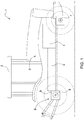
- the Fig. 1 shows an agricultural machine 1 in the form of a tractor with a cab 2 and a drive train 3, the drive train 3 comprising a drive motor 4 and a transmission 5.
- the drive motor 4 is designed as an internal combustion engine.
- a travel drive 8 is provided, which has an axle drive 9 and a permanently driven rear vehicle axle 6.
- the travel drive 8 comprises a front vehicle axle 7 that is driven as required.
- the transmission 5 according to the invention is in the Fig. 2 and 3 shown, with the Fig. 2 illustrated embodiment to a so-called two-shaft design and in the Fig. 3 is a so-called three-wave design.
- Fig. 2 three shafts 10, 20, 30 are provided, which are arranged parallel to one another and wherein the first shaft 10 and the second shaft 20 via a first switching group 40 and the second shaft 20 and the third shaft 30 via a second switching group 50 in connection with one another stand.
- the first shaft 10 is driven by the drive motor 4 and accordingly has a speed that is matched to the drive motor 4.
- a multi-plate clutch FWD is provided, via which the first shaft 10 can be coupled directly to an input outer shaft section 11.
- This input outer shaft section 11 surrounds the first shaft 10 on the circumference and, in a coupled state of the multi-plate clutch FWD, has the same speed as the first shaft 10.
- output outer shaft sections 45, 46 two further outer shaft sections are provided on the first shaft 10, which are referred to below as output outer shaft sections 45, 46.
- the second output outer shaft section 46 encloses both the first shaft 10 and the first output outer shaft section 45.
- the output outer shaft sections 45, 46 can be connected to the input outer shaft section 11 via a planetary arrangement 60, so that each of the two output outer shaft sections 45, 46 form its own power path of the first switching group 40 can, via which a mechanical power can be transmitted to the second shaft 20 in each case or together.
- the planetary arrangement 60 consists on the one hand of a planetary stage 61 and a planetary clutch 62, the planetary stage 61 having two sun gears arranged next to one another and two planet gears arranged next to one another, each with a planet carrier.
- the two planet carriers are directly coupled to one another and connected to the input outer shaft section 11 via a first sun gear.
- the planetary carriers are connected to the outer disk carrier of the planetary clutch 62 and the output-side sun gear is connected to the inner disk carrier of the planetary clutch 62.
- the inner disk carrier of the planetary clutch 62 is again connected to the first output outer shaft section 45 and the outer disk carrier is connected to the second output outer shaft section 46.
- Both output outer shaft sections 45, 46 each have two transmission units 41, 42, 43, 44 in the form of gear pairs, the drive gears of the transmission units 41, 42 being arranged on the first output outer shaft section 45 and the drive gears of the transmission units 43, 44 on the second output outer shaft section 46 .
- the output gears of the transmission units 41, 42, 43, 44 are arranged on the second shaft 20.
- either the transmission units 41, 42, 43, 44 can be switched individually or in each case in combination of a transmission unit 41, 42 of the first output outer shaft section 45 with a transmission unit 43, 44 of the second output outer shaft section 46, in which case the mechanical power is transmitted to the second shaft 20 via two power paths.
- Each transmission unit 41, 42, 43, 44 is also assigned a respective multi-plate clutch 41 ', 42', 43 ', 44'.
- the second switching group 50 is designed as a classic spur gear set in the form of a double clutch transmission.
- the double shift transmission contains two sub-transmissions, on each of which different transmission units 53, 55, 57 are arranged.
- auxiliary shafts 51a, 51b are provided to implement the partial transmissions.
- the secondary shaft 51b coincides with the output shaft 30.
- the auxiliary shaft 51a is driven via the output gear of the transmission unit with the drive gear 44, this drive gear 44 always rotating regardless of the position of the planetary clutch 62 and thus the auxiliary shaft 51 can always be driven.
- the individual sub-transmissions can be switched on by the multi-plate clutches 56a, 56b.
- synchronization units 54, 58 are provided, which on the one hand provide a gear as a direct clutch and at the same time also enable the individual transmission units 53, 55, 57 to be connected.
- the Fig. 3 shows the transmission according to the invention according to FIG Fig. 2 in a three-shaft arrangement, the third shaft 30 now no longer being arranged coaxially to the second shaft 20, but rather parallel to the first and the second shaft 10, 20. In such a configuration, a secondary shaft 51 is no longer required. However, the essential components remain essentially the same.
- the switching of the transmission unit 57 also requires the synchronization unit 58 to be switched to the corresponding position so that the mechanical power can be transmitted to the auxiliary shaft 51b or the output shaft 30. According to the Fig. 3 this is not necessary.
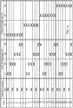
- the Fig. 4 shows the switching matrix for the forward operation of the agricultural machine 1 with a transmission according to FIG Fig. 2 .
- the switching matrix shows that only one transmission unit 41, 42, 43, 44 is switched alternately in the first switching group 40 and in a subsequent gear two transmission units 41, 42, 43, 44, the two transmission units 41, 42, 43, 44 are assigned to different output outer shaft sections 45, 46 and thus two different power paths. A total of seven gears are thus possible with four transmission units 41, 42, 43, 44.
- the circuit of the second switching group 50 is arranged downstream of the first switching group 40.
- the synchronization unit 58 can connect either the transmission unit 53 or the transmission unit 57.
- the synchronization unit 59 shifts either the transmission unit 57 or, in a direct gear, the auxiliary shaft 51b or the output shaft 30.
Landscapes
- Engineering & Computer Science (AREA)
- General Engineering & Computer Science (AREA)
- Mechanical Engineering (AREA)
- Structure Of Transmissions (AREA)
Abstract
Description
- Die Erfindung betrifft ein Getriebe mit zumindest einer ersten und einer zweiten Welle, wobei zumindest eine erste und eine zweite Schaltgruppe zwischen der ersten und der zweiten Welle angeordnet sind, wobei jede der Schaltgruppen zumindest zwei einzeln schaltbare Übertragungseinheiten zur Übertragung eines Drehmomentes aufweist, die sich hinsichtlich ihres Übersetzungsverhältnisses voneinander unterscheiden.
- Derartige Getriebe kommen üblicherweise als sogenannte Lastschaltgetriebe bei Landmaschinen zum Einsatz und dienen der Übertragung einer mechanischen Leistung von einem Antriebsmotor auf einen Antriebsstrang des entsprechenden Fahrzeuges. Hierbei ist es entscheidend, dass die Getriebe derart ausgelegt sind, dass einerseits eine große Spreizung gewährleistet wird und zugleich die zu synchronisierende Massenträgheit möglichst gering ist. Aus diesem Grunde weisen derartige Getriebe üblicherweise eine Vielzahl von Gängen auf, um die große Spreizung überbrücken zu können. Diese einzelnen Gänge werden durch die Schaltung der beiden Schaltgruppen zueinander realisiert, wobei die erste Schaltgruppe üblicherweise auch als Gangschaltgruppe und die zweite Schaltgruppe als Bereichsschaltgruppe bezeichnet wird. Sofern zumindest beide Schaltgruppen zumindest zwei Übertragungseinheiten aufweisen, lassen sich insgesamt vier Gänge realisieren, wobei sich die Mindestanzahl der Gänge aus dem Produkt der Anzahl beider Schaltgruppen ergibt.
- Ausgehend von diesem Stand der Technik ist es stets ein Bestreben, die Anzahl der Gänge zu erhöhen, um die Übergänge hinsichtlich der Übersetzungsverhältnisse zwischen den einzelnen Gängen möglichst fließend innerhalb der Spreizung ausbilden zu können. Darüber hinaus sollen diese Gänge auch möglichst unter Last schaltbar sein. Als Gang wird im Rahmen der Erfindung stets eine Kombination aus zugeschalteten Übertragungseinheiten der ersten und der zweiten Schaltgruppe verstanden, die zusammen ein bestimmtes Übersetzungsverhältnis zwischen der ersten und der zweiten Welle erzeugen.
- Der vorliegenden Erfindung liegt die Aufgabe zugrunde, ein Getriebe anzugeben, das sich gegenüber den bislang bekannten Getrieben durch eine große Anzahl von Gängen und einer zugleich geringen Anzahl von Kupplungen auszeichnet.
- Diese Aufgabe wird gelöst durch ein Getriebe gemäß Anspruch 1. Erfindungsgemäß kann die erste Schaltgruppe über eine Planetenstufe mit der ersten Welle in Wirkverbindung gebracht werden, wobei die Planetengruppe derart ausgebildet ist, dass eine über die erste Welle eingebrachte mechanische Leistung über einen ersten und/oder über einen zweiten zu- oder abkoppelbaren Leistungspfad auf die zweite Welle übertragbar ist, wobei jedem Leistungspfad zumindest eine Übertragungseinheit der ersten Schaltgruppe zugeordnet ist und wobei in zumindest einem Schaltzustand der ersten Schaltgruppe der Leistungsfluss über zumindest jeweils eine Übertragungseinheit des ersten und des zweiten Leistungspfades verläuft.
- Demnach ist die erste Schaltgruppe derart ausgebildet, dass die Leistung nicht nur über lediglich eine, sondern über zumindest zwei Leistungspfade übertragen werden kann, wobei die Übertragung der Leistung entsprechend über jeweils eine zugeordnete Übertragungseinheit erfolgt. Als Übertragungseinheit kommen beispielsweise Zahnradpaare in Betracht, wobei sich das Übersetzungsverhältnis eines solchen Zahnradpaares aus dem Durchmesserunterschied der einzelnen Zahnräder zueinander ergibt. Im Rahmen der Erfindung werden die Zahnräder dieser Zahnradpaare auch als Antriebszahnrad und als Abtriebszahnrad bezeichnet, wobei ein Drehmoment von dem Antriebszahnrad auf das Abtriebszahnrad übertragen wird. Bei einer Direktkupplung werden die beiden Wellen unmittelbar miteinander gekoppelt, sodass folglich das Übersetzungsverhältnis einen Wert von i=1 annimmt, wobei der Wert i für das Übersetzungsverhältnis steht und sich aus dem Verhältnis der Drehzahl der Antriebswelle zu der Drehzahl der Abtriebswelle ergibt. Ein solches Übersetzungsverhältnis kann selbstverständlich auch mit einem Zahnradpaar realisiert werden.
- In einer bevorzugten Ausgestaltung der Erfindung weist die erste Schaltgruppe zumindest zwei Außenwellenabschnitte auf, die die erste Welle koaxial umgeben, wobei jeweils zumindest eine der Übertragungseinheiten auf einem der Außenwellenabschnitte angeordnet ist und wobei ein erster Außenwellenabschnitt dem ersten Leistungspfad und ein zweiter Außenwellenabschnitt dem zweiten Leistungspfad zugeordnet ist. Demnach sind zumindest zwei Übertragungseinheiten auf zwei unabhängig voneinander rotierbaren Außenwellenabschnitten angeordnet. Hierdurch ist es möglich, dass beide Leistungspfade gleichzeitig zugeschaltet werden können, da die Drehzahl beider Außenwellenabschnitte voneinander entkoppelt werden kann.
- Für die Einbindung dieser Außenwellenabschnitte in die einzelnen Leistungspfade weist die Planetenstufe bevorzugt einen Leistungseingang und zumindest zwei Leistungsausgänge auf, die jeweils mit einem der Leistungspfade in Verbindung stehen, wobei zwischen den beiden Leistungsausgängen der Planetenstufe eine Planetenkupplung angeordnet ist, die in einem zugekoppelten Zustand die beiden Leistungsausgänge unmittelbar miteinander verbindet. Planetenstufen weisen üblicherweise eine Vielzahl einander umlaufender Räder auf, die entweder als Leistungseingang oder aber auch als Leistungsausgang dienen können. Beispielsweise können die Räder als Sonnenräder, Planetenräder und Hohlräder ausgestattet sein, wobei insbesondere Hohlräder keinen zwingenden Bestandteil einer solchen Planetenradstufe darstellen. Das Sonnenrad befindet sich im Zentrum der Planetenstufe und wird von den Planetenrädern umlaufen, wobei die Planetenräder über einen Planetenträger miteinander verbunden sind. Demnach können das Sonnenrad, der Planetenträger und auch das Hohlrad als Leistungseingang oder als Leistungsausgang dienen. Hierzu erfolgt eine Anbindung an die entsprechende Welle, wobei im Rahmen der Erfindung jeweils zwei Leistungsausgänge der Planetenstufe jeweils mit einem Außenwellenabschnitt verbunden bzw. verbindbar sind und wobei der Leistungseingang unmittelbar oder unter Einbindung einer zusätzlichen Übertragungseinheit mit der ersten Welle verbunden ist. Über diese zusätzliche Übertragungseinheit kann beispielsweise eine Unter- oder auch eine Übersetzung realisiert werden.
- Eine bevorzugte Ausgestaltung der Planetenstufe sieht zumindest zwei nebeneinander angeordnete Sonnenräder und zwei nebeneinander angeordnete Planetenradsätze vor, wobei jeder Planetenradsatz aus einem Planetenträger und einzelnen Planetenrädern besteht. Die Planetenträger sind unmittelbar miteinander gekoppelt und darüber hinaus als ein erster Leistungsausgang mit einem der Außenwellenabschnitte verbunden. Der zweite Leistungsausgang wird über ein Sonnenrad verwirklicht, das entsprechend mit dem anderen Außenwellenabschnitt verbunden ist. Als Leistungseingang dient das andere Sonnenrad, sodass jeweils ein Sonnenrad als Leistungseingang und ein Sonnenrad als Leistungsausgang vorgesehen ist. Die beiden nebeneinander angeordneten Sonnenräder und Planetenradsätze sind ferner bevorzugt so ausgelegt, dass diese sich hinsichtlich ihres Übersetzungsverhältnisses voneinander unterscheiden. So ist bevorzugt das Sonnenrad im Leistungseingang größer ausgebildet als im Leistungsausgang und die Planetenräder im Leistungseingang sind entsprechend kleiner ausgebildet als im Leistungsausgang.
- Durch Zukopplung der Planetenkupplung wird erreicht, dass beide Leistungsausgänge und damit beide Außenwellenabschnitte die gleiche Drehzahl aufweisen. Demnach erfolgt eine Zukopplung nur dann, wenn lediglich eine Übertragungseinheit zugeschaltet bzw. wenn die Leistung nur über einen Leistungspfad übermittelt werden soll. Sofern in beiden Leistungspfaden eine Zukopplung jeweils einer Übertragungseinheit erfolgen soll, muss die Planetenkupplung entkoppelt werden, sodass die beiden Drehzahlen der Außenwellenabschnitte bzw. in den beiden Leistungspfaden voneinander unabhängig sind. Gemäß einer bevorzugten Ausgestaltung ist die Planetenkupplung als Lamellenkupplung mit einem Innen- und einem Außenlamellenträger ausgeführt, wobei die Lamellenträger jeweils mit einem der Leistungsausgänge der Planetenstufe und einem der Leistungspfade, insbesondere mit einem der Außenwellenabschnitte, in Verbindung stehen. Bevorzugt ist der äußere Lamellenträger mit dem Planetenträger der Planetenstufe und der innere Lamellenträger mit dem als Leistungsausgang fungierenden Sonnenrad der Planetenstufe verbunden.
- Auch ist bevorzugt jeder Übertragungseinheit der ersten Schaltgruppe eine Kupplung zugeordnet, die ebenfalls bevorzugt als Lamellenkupplung ausgebildet ist und über die die Übertragungseinheit zu- oder entkoppelt werden kann.
- Auch zwischen der ersten Welle und dem Leistungseingang der Planetenstufe ist bevorzugt eine Kupplung, insbesondere eine Lamellenkupplung, vorgesehen. Dies hat den Vorteil, dass in einer einfachen Art und Weise eine Reversiereinheit zwischen der ersten Welle und der Planetenstufe angeordnet werden kann, die ebenfalls koppelbar ausgebildet ist und die im zugekoppelten Zustand eine Umkehrung der Drehrichtung der Planetenstufe bewirkt. In einem solchen Fall wird die Kupplung zwischen der ersten Welle und dem Leistungseingang der Planetenstufe gelöst, wobei vorzugsweise auch der Leistungseingang, z. B. an dem Sonnenrad der Planetenstufe, mit einem Außenwellenabschnitt verbunden ist, der die erste Welle koaxial umschließt. An diesen Außenwellenabschnitt schließt demnach nicht nur die Kupplung an, die eine Verbindung zwischen der ersten Welle und dem Leistungseingang bewirkt, sondern auch eine Reversierübertragungseinheit, die Teil der Reversiereinheit ist und eine Umkehrung der Drehrichtung bewirkt. Diese Reversierübertragungseinheit kann beispielsweise in Form eines dreiteiligen Zahnradsatzes ausgebildet sein und kann entsprechend über eine Reversierkupplung, z. B. eine Lamellenkupplung, zu- oder entkoppelt werden. Demnach wird diese Reversierkupplung nur dann betätigt, wenn eine Umkehrung der Drehrichtung erforderlich ist, wobei dann zugleich die Kupplung zwischen der ersten Welle und dem Leistungseingang bzw. dem Außenwellenabschnitt des ersten Leistungseinganges entkoppelt ist.
- Insgesamt hat es sich als besonders vorteilhaft erwiesen, wenn die Reversiereinheit vor der Planetenstufe und damit auch vor den beiden Schaltgruppen angeordnet ist, sodass auch bei einer reversierten Drehrichtung, z. B. bei einer Rückwärtsfahrt die volle Anzahl an Gängen zur Verfügung steht und somit auch im Rückwärtsbetrieb die Getriebespreizung möglichst lückenlos ausgefüllt wird.
- Gemäß einer Weiterbildung der Erfindung ist eine dritte Welle zwischen der ersten und der zweiten Welle angeordnet, wobei die erste Schaltgruppe zwischen der ersten und der zweiten Welle und die zweite Schaltgruppe zwischen der zweiten und der dritten Welle angeordnet sind. Die zweite und die dritte Welle können beispielsweise koaxial nebeneinander oder parallel zueinander angeordnet sein. Bei einer Anordnung koaxial zueinander spricht man von einer sogenannten Zwei-Wellen-Anordnung und bei einer parallelen Anordnung von einer Drei-Wellen-Anordnung, da alle drei Wellen parallel zueinander ausgerichtet sind, sodass sich entsprechend in einer senkrecht zur Drehachse der einzelnen Wellen erstreckenden Richtung der Bauraum im Vergleich zu einer Zwei-Wellen-Anordnung größer ist.
- Bevorzugt ist die zweite Schaltgruppe mit zumindest einer Synchronisiereinheit ausgebildet. Mit Hilfe einer solchen Synchronisierungseinheit kann der Leistungspfad der zweiten Schaltgruppe vorgewählt werden. Das bedeutet, dass die Synchronisierungseinheiten bestimmen, über welchen Leistungspfad der zweiten Schaltgruppe übertragen werden soll. Die zweite Schaltgruppe ist hierzu bevorzugt in Form eines Doppelkupplungsgetriebes ausgebildet, so dass die Übertragungseinheiten in zwei separate Teilgetriebe aufgeteilt sind. Die Schaltung der Übersetzungseinheiten erfolgt dann über die Schaltung der Synchronisiereinheiten, wobei die Teilgetriebe über jeweils eine Kupplung z. B. eine Lamellenkupplung zugeschaltet werden. Das Schalten der Synchronisiereinheiten wird auch als Vorwählen bezeichnet.
- Bei einer Synchronisiereinheit werden ähnlich wie bei einer Lamellenkupplung zwei koaxial zueinander angeordnete und rotierbare Wellen über einen Synchronring stirnseitig kontaktiert, wobei der Synchronring einen Reibschluss zwischen den einzelnen Wellen ausbildet und zu einer Synchronisierung der Rotationsgeschwindigkeiten führt.
- Hierbei können die Synchronisiereinheiten auch so ausgebildet sein, dass diese jeweils mehrere z. B. zwei Leistungspfade vorwählen können. Demnach weisen die Synchronisiereinheiten dann z. B. drei Schaltzustände auf, wobei in einem ersten Schaltzustand eine erste Übertragungseinheit, in einem zweiten Schaltzustand eine zweite Übertragungseinheit und in einem dritten Schaltzustand keine Übertragungseinheit zukoppelt werden kann.
- Bevorzugt weisen die erste und/oder die zweite Schaltgruppe zumindest drei, vorzugsweise zumindest vier Übertragungseinheiten auf, wobei aber auch jeweils weitere Übertragungseinheiten, z. B. fünf, sechs oder mehr Übertragungseinheiten, vorgesehen sein können. Bei einer exemplarischen Anzahl von vier Übertragungseinheiten in der ersten Schaltgruppe ergeben sich für die erste Schaltgruppe insgesamt sieben Schaltzustände, da auch jeweils zwei Übertragungseinheiten in jeweils einem unterschiedlichen Leistungspfad miteinander geschaltet werden können. Die zweite Schaltgruppe übertragt die mechanische Leistung bevorzugt lediglich über einen Leistungspfad, sodass bei entsprechend auf vier Übertragungseinheiten in der zweiten Schaltgruppe insgesamt 28 Gänge möglich sind. Diese Anzahl von Gängen steht hierbei bevorzugt sowohl in einer Vorwärtsfahrt als auch in einer Rückwärtsfahrt zur Verfügung. Bei lediglich drei Übertragungseinheiten sowohl in der ersten als auch in der zweiten Schaltgruppe ergibt sich insgesamt eine Anzahl von 15 Gängen sowohl in der Vorwärts- als auch in der Rückwärtsfahrt.
- Gegenstand der Erfindung ist auch die Verwendung eines erfindungsgemäßen Getriebes in einer Landmaschine, insbesondere einen Traktor gemäß Patentanspruch 12 sowie ein Verfahren zum Betrieb eines erfindungsgemäßen Getriebes gemäß Anspruch 13.
- Gemäß diesem Verfahren werden die Schaltzustände der ersten Schaltgruppe derart durchlaufen, dass abwechselnd entweder nur eine Übertragungseinheit des ersten Leistungspfades oder jeweils eine Übertragungseinheit sowohl im ersten als auch zumindest im zweiten Leistungspfad zugeschaltet sind. Bevorzugt ist hierbei bei einer gemeinsamen Schaltung des ersten und des zweiten Leistungspfades die Planetenkupplung zwischen den Leistungsausgängen der Planetenstufe nicht zugekoppelt.
- Gemäß einer bevorzugten Weiterbildung des Verfahrens werden nacheinander erst die Schaltzustände der ersten Schaltgruppe und erst danach die Schaltzustände der zweiten Schaltgruppe durchlaufen. Dies bedeutet, dass bei einem Hochschalten des Getriebes zunächst erst alle Schaltzustände der ersten Schaltgruppe durchlaufen werden, erst dann wird die zweite Schaltgruppe in einen neuen Schaltzustand gebracht und die einzelnen Schaltzustände der ersten Schaltgruppe noch einmal durchlaufen. Diese Reihenfolge wird beibehalten, bis auch der letzte Schaltzustand in der zweiten Schaltgruppe erreicht ist.
- Im Folgenden wird die Erfindung anhand eines exemplarischen Ausführungsbeispiels näher erläutert. Es zeigen:
- Fig. 1
- eine Landmaschine mit einem Antriebsstrang, der ein erfindungsgemäßes Getriebe umfasst,
- Fig. 2
- ein erfindungsgemäßes Getriebe im Zwei-Wellen-Design,
- Fig. 3
- ein erfindungsgemäßes Getriebe im Drei-Wellen-Design,
- Fig. 4
- eine Schaltmatrix für den Vorwärtsbetrieb des erfindungsgemäßen Getriebes gemäß der
Figur 2 . - Die
Fig. 1 zeigt eine Landmaschine 1 in Gestalt eines Traktors mit einer Kabine 2 und einem Antriebsstrang 3, wobei der Antriebsstrang 3 einen Antriebsmotor 4 und ein Getriebe 5 umfasst. Der Antriebsmotor 4 ist als Verbrennungskraftmaschine ausgeführt. Ferner ist ein Fahrantrieb 8 vorgesehen, der ein Achsgetriebe 9 und eine permanent angetriebene hintere Fahrzeugachse 6 aufweist. Zusätzlich umfasst der Fahrantrieb 8 eine bedarfsweise angetriebene vordere Fahrzeugachse 7. - Das erfindungsgemäße Getriebe 5 ist in den
Fig. 2 und3 dargestellt, wobei es sich bei der in derFig. 2 dargestellten Ausführungsform um ein sogenanntes Zwei-Wellen-Design und in derFig. 3 um ein sogenanntes Drei-Wellen-Design handelt. - Gemäß der
Fig. 2 sind drei Wellen 10, 20, 30 vorgesehen, die parallel zueinander angeordnet sind und wobei jeweils die erste Welle 10 und die zweite Welle 20 über eine erste Schaltgruppe 40 und die zweite Welle 20 und die dritte Welle 30 über eine zweite Schaltgruppe 50 miteinander in Verbindung stehen. Die erste Welle 10 wird von dem Antriebsmotor 4 angetrieben und weist demnach eine dem Antriebsmotor 4 angeglichene Drehzahl auf. Am hinteren Ende der ersten Welle 10 ist eine Lamellenkupplung FWD vorgesehen, über die die erste Welle 10 mit einem Eingangsaußenwellenabschnitt 11 direkt gekoppelt werden kann. Dieser Eingangsaußenwellenabschnitt 11 umschließt die erste Welle 10 umfangseitig und weist in einem zugekoppelten Zustand der Lamellenkupplung FWD die gleiche Drehzahl auf wie auch die erste Welle 10. - Darüber hinaus sind zwei weitere Außenwellenabschnitte auf der ersten Welle 10 vorgesehen, die im Folgenden als Ausgangsaußenwellenabschnitte 45, 46 bezeichnet werden. Der zweite Ausgangsaußenwellenabschnitt 46 umschließt hierbei sowohl die erste Welle 10 als auch den ersten Ausgangsaußenwellenabschnitt 45. Die Ausgangsaußenwellenabschnitte 45, 46 sind über eine Planetenanordnung 60 mit dem Eingangsaußenwellenabschnitt 11 verbindbar, sodass jeder der beiden Ausgangsaußenwellenabschnitte 45, 46 einen eigenen Leistungspfad der ersten Schaltgruppe 40 bilden kann, über die jeweils oder gemeinsam eine mechanische Leistung auf die zweite Welle 20 übertragbar ist.
- Die Planetenanordnung 60 besteht einerseits aus einer Planetenstufe 61 sowie einer Planetenkupplung 62, wobei die Planetenstufe 61 zwei nebeneinander angeordnete Sonnenräder und zwei nebeneinander angeordnete Planetenräder mit jeweils einem Planetenträger aufweist. Die beiden Planetenträger sind hierbei unmittelbar miteinander gekoppelt und über ein erstes Sonnenrad mit dem Eingangsaußenwellenabschnitt 11 verbunden. Ausgangsseitig sind die Planetenträger mit dem äußeren Lamellenträger der Planetenkupplung 62 und das ausgangsseitige Sonnenrad mit dem inneren Lamellenträger der Planetenkupplung 62 verbunden. Bei einer weiteren Betrachtung wird deutlich, dass wiederum der innere Lamellenträger der Planetenkupplung 62 mit dem ersten Ausgangsaußenwellenabschnitt 45 und der äußere Lamellenträger mit dem zweiten Ausgangsaußenwellenabschnitt 46 verbunden ist.
- Beide Ausgangsaußenwellenabschnitte 45, 46 weisen jeweils zwei Übertragungseinheiten 41, 42, 43, 44 in Form von Zahnradpaaren auf, wobei die Antriebszahnräder der Übertragungseinheiten 41,42 auf dem ersten Ausgangsaußenwellenabschnitt 45 und die Antriebszahnräder der Übertragungseinheiten 43, 44 auf dem zweiten Ausgangsaußenwellenabschnitt 46 angeordnet sind. Die Abtriebszahnräder der Übertragungseinheiten 41, 42, 43, 44 sind auf der zweiten Welle 20 angeordnet sind. Durch eine solche Ausgestaltung können entweder die Übertragungseinheiten 41, 42, 43, 44 einzeln geschaltet oder aber auch jeweils in Kombination einer Übertragungseinheit 41, 42 des ersten Ausgangsaußenwellenabschnittes 45 mit einer Übertragungseinheit 43, 44 des zweiten Ausgangsaußenwellenabschnittes 46 geschaltet werden, wobei dann die mechanische Leistung über zwei Leistungspfade auf die zweite Welle 20 übertragen wird. Jeder Übertragungseinheit 41, 42, 43, 44 ist darüber hinaus jeweils eine Lamellenkupplung 41', 42', 43', 44' zugeordnet.
- Die zweite Schaltgruppe 50 ist als klassischer Stirnradsatz in Form eines Doppelkupplungsgetriebes ausgebildet. Das Doppelschaltgetriebe beinhaltet zwei Teilgetriebe, an denen jeweils unterschiedliche Übertragungseinheiten 53, 55, 57 angeordnet sind. Ferner sind zur Realisierung der Teilgetriebe Nebenwellen 51a, 51b vorgesehen. Die Nebenwelle 51b fällt hierbei mit der Abtriebswelle 30 zusammen. Die Nebenwelle 51a wird angetrieben über das Abtriebszahnrad der Übertragungseinheit mit dem Antriebszahnrad 44, wobei dieses Antriebszahnrad 44 unabhängig von der Stellung der Planetenkupplung 62 immer in Rotation ist und somit auch stets die Nebenwelle 51 angetrieben werden kann. Die einzelnen Teilgetriebe können durch die Lamellenkupplungen 56a, 56b zugeschaltet werden.
- Ferner sind Synchronisiereinheiten 54, 58 vorgesehen, die einerseits einen Gang als Direktkupplung bereitstellen und zugleich auch eine Anbindung der einzelnen Übertragungseinheiten 53, 55, 57 ermöglichen.
- Die
Fig. 3 zeigt das erfindungsgemäße Getriebe gemäß derFig. 2 in einer Drei-Wellen-Anordnung, wobei die dritte Welle 30 nunmehr nicht mehr koaxial zur zweiten Welle 20, sondern parallel zu der ersten und der zweiten Welle 10, 20 angeordnet ist. Bei einer solchen Ausgestaltung ist eine Nebenwelle 51 nicht mehr erforderlich. Die wesentlichen Komponenten bleiben jedoch im Wesentlichen gleich. Im Unterschied zu dem Getriebe gemäß derFig. 2 setzt das Schalten der Übertragungseinheit 57 zusätzlich das Schalten der Synchronisierungseinheit 58 in die entsprechende Stellung voraus, damit die mechanische Leistung auf die Nebenwelle 51b bzw. die Ausgangswelle 30 übertragen werden kann. Gemäß derFig. 3 ist dies nicht erforderlich. - Die
Fig. 4 zeigt die Schaltmatrix für den Vorwärtsbetrieb der Landmaschine 1 mit einem Getriebe gemäß derFig. 2 . Anhand der Schaltmatrix ist sichtbar, dass jeweils abwechselnd immer erst nur eine Übertragungseinheit 41, 42, 43, 44 in der ersten Schaltgruppe 40 geschaltet wird und in einem darauffolgenden Gang jeweils zwei Übertragungseinheiten 41, 42, 43, 44, wobei die beiden Übertragungseinheiten 41, 42, 43, 44 unterschiedlichen Ausgangsaußenwellenabschnitten 45, 46 und damit zwei unterschiedlichen Leistungspfaden zugeordnet sind. Insgesamt sind somit bei vier Übertragungseinheiten 41, 42, 43, 44 insgesamt sieben Gänge möglich. Die Schaltung der zweiten Schaltgruppe 50 ist der ersten Schaltgruppe 40 nachgeordnet. Die Synchronisierungseinheit 58 kann hierbei entweder die Übertragungseinheit 53 oder die Übertragungseinheit 57 zuschalten. Im Gegensatz dazu schaltet die Synchronisierungseinheit 59 entweder die Übertragungseinheit 57 oder in einem Direktgang die Nebenwelle 51b bzw. die Ausgangswelle 30.
Claims (15)
- Getriebe (5) mit zumindest einer ersten und einer zweiten Welle (10, 30), wobei zumindest eine erste und eine zweite Schaltgruppe (40, 50) zwischen der ersten und der zweiten Welle (10, 30) angeordnet sind, wobei jede der Schaltgruppen (40, 50) zumindest zwei einzeln schaltbare Übertragungseinheiten aufweist, die sich hinsichtlich ihres Übersetzungsverhältnisses voneinander unterscheiden, dadurch gekennzeichnet, dass
die erste Schaltgruppe (40) über eine Planetenstufe (60) mit der ersten Welle (10) in Wirkverbindung gebracht werden kann, die derart ausgebildet ist, dass eine über die erste Welle (10) eingebrachte mechanische Leistung über einen ersten und/oder über einen zweiten zu- oder abkoppelbaren Leistungspfad auf die zweite Welle (30) übertragbar ist,
wobei jedem Leistungspfad zumindest eine Übertragungseinheit der ersten Schaltgruppe (40) zugeordnet ist und wobei in zumindest einem Schaltzustand der ersten Schaltgruppe (40) der Leistungsfluss über zumindest jeweils eine Übertragungseinheit des ersten und des zweiten Leistungspfades verläuft. - Getriebe nach Anspruch 1,
wobei die erste Schaltgruppe (40) zumindest zwei Außenwellenabschnitte (45, 46) aufweist, die die erste Welle (10) koaxial umgeben,
wobei jeweils zumindest eine der Übertragungseinheiten einem der Außenwellenabschnitte (45, 46) zugeordnet ist, und
wobei ein erster Außenwellenabschnitt (45) dem ersten Leistungspfad und ein zweiter Außenwellenabschnitt (46) dem zweiten Leistungspfad zugeordnet ist. - Getriebe nach Anspruch 1 oder 2,
wobei die Planetenstufe einen Leistungseingang und zumindest zwei Leistungsausgänge aufweist, die jeweils mit einem der Leistungspfade in Verbindung stehen,
wobei zwischen den beiden Leistungsausgängen der Planetenstufe (60) eine Planetenkupplung (62) angeordnet ist, die in einem zugekoppelten Zustand die beiden Leistungsausgänge unmittelbar miteinander verbindet. - Getriebe nach Anspruch 3,
wobei der erste Leistungsausgang mit dem ersten Außenwellenabschnitt (45) und der zweite Leistungsausgang mit dem zweiten Außenwellenabschnitt (46) verbunden sind. - Getriebe nach Anspruch 3 oder 4,
wobei die Planetenkupplung (62) eine Lamellenkupplung mit einem Innen- und einem Außenlamellenträger ist,
wobei die Lamellenträger jeweils mit einem der Leistungsausgänge der Planetenstufe (62) und einem der Leistungspfade, insbesondere mit einem der Außenwellenabschnitte (45, 46) in Verbindung stehen. - Getriebe nach einem der Ansprüche 1 bis 5,
wobei die Übertragungseinheiten zumindest teilweise als Zahnradpaare und/oder als Direktkupplung ausgebildet sind. - Getriebe nach einem der Ansprüche 1 bis 6,
wobei zwischen der ersten Welle (10) und der Planetenstufe (60) eine koppelbare Reversiereinheit (70) angeordnet ist, die im zugekoppelten Zustand eine Umkehrung der Drehrichtung der Planetenstufe (60) bewirkt. - Getriebe nach einem der Ansprüche 1 bis 7,
wobei eine dritte Welle (20) zwischen der ersten (10) und der zweiten Welle (30) angeordnet ist, wobei die erste Schaltgruppe (40) zwischen der ersten und der zweiten Welle (10, 20) und die zweite Schaltgruppe (50) zwischen der zweiten und der dritten Welle (20, 30) angeordnet sind. - Getriebe nach einem der Ansprüche 1 bis 8,
wobei zumindest jeder Übertragungseinheit der ersten Schaltgruppe (40) eine Kupplung, insbesondere eine Lamellenkupplung, zugeordnet ist, über die die Übertragungseinheit zu- oder abgekoppelt werden kann. - Getriebe nach einem der Ansprüche 1 bis 9,
wobei die Übertragungseinheiten der zweiten Schaltgruppe (50) zumindest teilweise über eine Synchronisiereinheit (59, 58) zu- oder abgekoppelt werden können. - Getriebe nach einem der Ansprüche 1 bis 10,
wobei die erste und/oder die zweite Schaltgruppe (40, 50) zumindest drei, vorzugsweise zumindest vier Übertragungseinheiten aufweist. - Verwendung eines Getriebes (5) gemäß einem der Ansprüche 1 bis 11 in einer Landmaschine (1), insbesondere einem Traktor.
- Verfahren zum Betrieb eines Getriebes (5) nach einem der Ansprüche 1 bis 11, wobei die Schaltzustände der ersten Schaltgruppe (40) derart durchlaufen werden, dass abwechselnd entweder nur eine Übertragungseinheit des ersten Leistungspfades oder jeweils eine Übertragungseinheit sowohl im ersten als auch zumindest im zweiten Leistungspfad zugeschaltet sind.
- Verfahren nach Anspruch 13, wobei bei einer gemeinsamen Schaltung des ersten und des zweiten Leistungspfades die Planetenkupplung (62) zwischen den Leistungsausgängen der Planetenstufe nicht zugekoppelt ist.
- Verfahren nach Anspruch 13 oder 14, wobei nacheinander erst die Schaltzustände der ersten Schaltgruppe (40) und erst danach die Schaltzustände der zweiten Schaltgruppe (50) durchlaufen werden.
Applications Claiming Priority (1)
| Application Number | Priority Date | Filing Date | Title |
|---|---|---|---|
| DE102019216300.9A DE102019216300A1 (de) | 2019-10-23 | 2019-10-23 | Getriebe, Verwendung eines Getriebes und Verfahren für ein Getriebe |
Publications (2)
| Publication Number | Publication Date |
|---|---|
| EP3812621A1 true EP3812621A1 (de) | 2021-04-28 |
| EP3812621B1 EP3812621B1 (de) | 2022-09-28 |
Family
ID=72658966
Family Applications (1)
| Application Number | Title | Priority Date | Filing Date |
|---|---|---|---|
| EP20198068.7A Active EP3812621B1 (de) | 2019-10-23 | 2020-09-24 | Getriebe, verwendung eines getriebes und verfahren für ein getriebe |
Country Status (3)
| Country | Link |
|---|---|
| US (1) | US11187310B2 (de) |
| EP (1) | EP3812621B1 (de) |
| DE (1) | DE102019216300A1 (de) |
Families Citing this family (5)
| Publication number | Priority date | Publication date | Assignee | Title |
|---|---|---|---|---|
| DE102019216299A1 (de) | 2019-10-23 | 2021-04-29 | Deere & Company | Schaltgruppe für Lastschaltgetriebe |
| DE102019216303A1 (de) * | 2019-10-23 | 2021-04-29 | Deere & Company | Getriebe |
| DE102020121209A1 (de) | 2020-08-12 | 2022-02-17 | Deere & Company | Lastschaltgetriebe und Fahrzeug |
| DE102021207657B4 (de) | 2021-07-19 | 2023-03-16 | Zf Friedrichshafen Ag | Getriebeanordnung und Hybridgetriebeanordnung für ein Kraftfahrzeug |
| US12044296B2 (en) | 2021-12-20 | 2024-07-23 | Deere & Company | Power shift transmission |
Citations (3)
| Publication number | Priority date | Publication date | Assignee | Title |
|---|---|---|---|---|
| DE102011084037A1 (de) * | 2011-09-02 | 2013-03-07 | Schaeffler Technologies AG & Co. KG | Kraftfahrzeuggetriebe |
| DE102014226469A1 (de) * | 2014-12-18 | 2016-06-23 | Zf Friedrichshafen Ag | Umlaufrädergetriebe |
| EP3109509A1 (de) * | 2015-06-25 | 2016-12-28 | Deere & Company | Getriebeanordnung |
Family Cites Families (9)
| Publication number | Priority date | Publication date | Assignee | Title |
|---|---|---|---|---|
| JP4968494B2 (ja) | 2001-03-05 | 2012-07-04 | アイシン・エィ・ダブリュ株式会社 | 車両用変速機 |
| DE10260179A1 (de) | 2002-12-20 | 2004-07-01 | Zf Friedrichshafen Ag | Mehrganggetriebe in Vorgelenebauweise mit Leistungsverzweigung |
| US8596157B2 (en) | 2010-08-25 | 2013-12-03 | Deere & Company | Powershift transmission with twenty-four forward modes |
| DE102012021599B4 (de) * | 2012-10-30 | 2018-10-04 | Audi Ag | Schaltvorrichtung für ein Doppelkupplungsgetriebe |
| DE102012220829A1 (de) * | 2012-11-15 | 2014-05-15 | Zf Friedrichshafen Ag | Verfahren zum Betreiben einer Antriebseinheit für ein Hybridfahrzeug |
| US9879761B2 (en) | 2014-10-30 | 2018-01-30 | Deere & Company | Powershift transmission with twenty-seven forward modes |
| DE102015208164A1 (de) | 2015-05-04 | 2016-11-10 | Deere & Company | Getriebeanordnung |
| DE102015208166A1 (de) | 2015-05-04 | 2016-11-10 | Deere & Company | Getriebeanordnung |
| US10086686B2 (en) | 2016-01-14 | 2018-10-02 | Deere & Company | Transmission with a mode selection apparatus |
-
2019
- 2019-10-23 DE DE102019216300.9A patent/DE102019216300A1/de not_active Withdrawn
-
2020
- 2020-09-24 EP EP20198068.7A patent/EP3812621B1/de active Active
- 2020-10-12 US US17/068,178 patent/US11187310B2/en active Active
Patent Citations (3)
| Publication number | Priority date | Publication date | Assignee | Title |
|---|---|---|---|---|
| DE102011084037A1 (de) * | 2011-09-02 | 2013-03-07 | Schaeffler Technologies AG & Co. KG | Kraftfahrzeuggetriebe |
| DE102014226469A1 (de) * | 2014-12-18 | 2016-06-23 | Zf Friedrichshafen Ag | Umlaufrädergetriebe |
| EP3109509A1 (de) * | 2015-06-25 | 2016-12-28 | Deere & Company | Getriebeanordnung |
Also Published As
| Publication number | Publication date |
|---|---|
| EP3812621B1 (de) | 2022-09-28 |
| US11187310B2 (en) | 2021-11-30 |
| US20210123511A1 (en) | 2021-04-29 |
| DE102019216300A1 (de) | 2021-05-12 |
Similar Documents
| Publication | Publication Date | Title |
|---|---|---|
| EP3812621B1 (de) | Getriebe, verwendung eines getriebes und verfahren für ein getriebe | |
| DE102006058831B4 (de) | Mehrganggetriebe mit Differentialzahnradsatz und Vorgelegewellen-Zahnradanordnung | |
| EP2914874B1 (de) | Doppelkupplungsgetriebe | |
| DE102021211734B3 (de) | Drei- oder Vierganggetriebe für einen elektrischen Antrieb | |
| DE102014209970A1 (de) | Getriebe für ein Kraftfahrzeug | |
| DE102014004691B4 (de) | Geschwindigkeits-Wechselgetriebe für ein Kraftfahrzeug | |
| EP3532325A1 (de) | Hybridantriebsstrang für ein hybridgetriebenes kraftfahrzeug | |
| EP3259499A1 (de) | Doppelkupplungsgetriebe für ein kraftfahrzeug | |
| DE102019207925A1 (de) | Nebenabtriebsgetriebe und landwirtschaftliche Arbeitsmaschine | |
| WO2018145882A1 (de) | Doppelkupplungsgetriebe mit brückenkupplung | |
| DE102010061919A1 (de) | Zahnräderwechselgetriebe, umfassend eine Splitgruppe | |
| DE102016111282B4 (de) | Doppelkupplungsgetriebe mit Brückenkupplung | |
| DE102019204891B4 (de) | Leistungsverzweigungsgetriebe sowie Verfahren zum Betrieb eines Leistungsverzweigungsgetriebes und Antriebsstrang | |
| EP3812618A1 (de) | Schaltgruppe für lastschaltgetriebe | |
| EP3472490B1 (de) | Doppelkupplungsgetriebe mit brückenkupplung | |
| DE102022207638A1 (de) | Kraftfahrzeuggetriebe | |
| EP2864661B1 (de) | Getriebe-kupplungseinheit und verfahren zur steuerung einer getriebeanordnung damit | |
| EP3770465A1 (de) | Getriebe | |
| DE102023206307B4 (de) | Lastschaltbares Getriebe und Verfahren zum Schalten eines lastschaltbaren Getriebes | |
| DE102020203795A1 (de) | Doppelkupplungsgetriebe und Hybrid-Antriebsstrang | |
| DE102024208112A1 (de) | Doppelkupplungsgetriebe für ein Kraftfahrzeug | |
| DE102021205932A1 (de) | Getriebe und Antriebsstrang für ein Kraftfahrzeug | |
| WO2016128156A1 (de) | Doppelkupplungsgetriebe sowie verfahren zum betreiben eines doppelkupplungsgetriebes | |
| DE102019216121A1 (de) | Getriebe für ein Kraftfahrzeug | |
| DE102020203791A1 (de) | Doppelkupplungsgetriebe und Hybrid-Antriebsstrang |
Legal Events
| Date | Code | Title | Description |
|---|---|---|---|
| PUAI | Public reference made under article 153(3) epc to a published international application that has entered the european phase |
Free format text: ORIGINAL CODE: 0009012 |
|
| STAA | Information on the status of an ep patent application or granted ep patent |
Free format text: STATUS: THE APPLICATION HAS BEEN PUBLISHED |
|
| AK | Designated contracting states |
Kind code of ref document: A1 Designated state(s): AL AT BE BG CH CY CZ DE DK EE ES FI FR GB GR HR HU IE IS IT LI LT LU LV MC MK MT NL NO PL PT RO RS SE SI SK SM TR |
|
| AX | Request for extension of the european patent |
Extension state: BA ME |
|
| STAA | Information on the status of an ep patent application or granted ep patent |
Free format text: STATUS: REQUEST FOR EXAMINATION WAS MADE |
|
| 17P | Request for examination filed |
Effective date: 20211028 |
|
| RBV | Designated contracting states (corrected) |
Designated state(s): AL AT BE BG CH CY CZ DE DK EE ES FI FR GB GR HR HU IE IS IT LI LT LU LV MC MK MT NL NO PL PT RO RS SE SI SK SM TR |
|
| RIC1 | Information provided on ipc code assigned before grant |
Ipc: F16H 37/08 20060101ALI20220328BHEP Ipc: F16H 37/04 20060101AFI20220328BHEP |
|
| GRAP | Despatch of communication of intention to grant a patent |
Free format text: ORIGINAL CODE: EPIDOSNIGR1 |
|
| STAA | Information on the status of an ep patent application or granted ep patent |
Free format text: STATUS: GRANT OF PATENT IS INTENDED |
|
| INTG | Intention to grant announced |
Effective date: 20220510 |
|
| GRAS | Grant fee paid |
Free format text: ORIGINAL CODE: EPIDOSNIGR3 |
|
| GRAA | (expected) grant |
Free format text: ORIGINAL CODE: 0009210 |
|
| STAA | Information on the status of an ep patent application or granted ep patent |
Free format text: STATUS: THE PATENT HAS BEEN GRANTED |
|
| AK | Designated contracting states |
Kind code of ref document: B1 Designated state(s): AL AT BE BG CH CY CZ DE DK EE ES FI FR GB GR HR HU IE IS IT LI LT LU LV MC MK MT NL NO PL PT RO RS SE SI SK SM TR |
|
| REG | Reference to a national code |
Ref country code: GB Ref legal event code: FG4D Free format text: NOT ENGLISH |
|
| REG | Reference to a national code |
Ref country code: CH Ref legal event code: EP |
|
| REG | Reference to a national code |
Ref country code: AT Ref legal event code: REF Ref document number: 1521418 Country of ref document: AT Kind code of ref document: T Effective date: 20221015 |
|
| REG | Reference to a national code |
Ref country code: DE Ref legal event code: R096 Ref document number: 502020001770 Country of ref document: DE |
|
| REG | Reference to a national code |
Ref country code: IE Ref legal event code: FG4D Free format text: LANGUAGE OF EP DOCUMENT: GERMAN |
|
| REG | Reference to a national code |
Ref country code: LT Ref legal event code: MG9D |
|
| PG25 | Lapsed in a contracting state [announced via postgrant information from national office to epo] |
Ref country code: SE Free format text: LAPSE BECAUSE OF FAILURE TO SUBMIT A TRANSLATION OF THE DESCRIPTION OR TO PAY THE FEE WITHIN THE PRESCRIBED TIME-LIMIT Effective date: 20220928 Ref country code: RS Free format text: LAPSE BECAUSE OF FAILURE TO SUBMIT A TRANSLATION OF THE DESCRIPTION OR TO PAY THE FEE WITHIN THE PRESCRIBED TIME-LIMIT Effective date: 20220928 Ref country code: NO Free format text: LAPSE BECAUSE OF FAILURE TO SUBMIT A TRANSLATION OF THE DESCRIPTION OR TO PAY THE FEE WITHIN THE PRESCRIBED TIME-LIMIT Effective date: 20221228 Ref country code: LV Free format text: LAPSE BECAUSE OF FAILURE TO SUBMIT A TRANSLATION OF THE DESCRIPTION OR TO PAY THE FEE WITHIN THE PRESCRIBED TIME-LIMIT Effective date: 20220928 Ref country code: LT Free format text: LAPSE BECAUSE OF FAILURE TO SUBMIT A TRANSLATION OF THE DESCRIPTION OR TO PAY THE FEE WITHIN THE PRESCRIBED TIME-LIMIT Effective date: 20220928 Ref country code: FI Free format text: LAPSE BECAUSE OF FAILURE TO SUBMIT A TRANSLATION OF THE DESCRIPTION OR TO PAY THE FEE WITHIN THE PRESCRIBED TIME-LIMIT Effective date: 20220928 |
|
| REG | Reference to a national code |
Ref country code: NL Ref legal event code: MP Effective date: 20220928 |
|
| PG25 | Lapsed in a contracting state [announced via postgrant information from national office to epo] |
Ref country code: HR Free format text: LAPSE BECAUSE OF FAILURE TO SUBMIT A TRANSLATION OF THE DESCRIPTION OR TO PAY THE FEE WITHIN THE PRESCRIBED TIME-LIMIT Effective date: 20220928 Ref country code: GR Free format text: LAPSE BECAUSE OF FAILURE TO SUBMIT A TRANSLATION OF THE DESCRIPTION OR TO PAY THE FEE WITHIN THE PRESCRIBED TIME-LIMIT Effective date: 20221229 |
|
| PG25 | Lapsed in a contracting state [announced via postgrant information from national office to epo] |
Ref country code: SM Free format text: LAPSE BECAUSE OF FAILURE TO SUBMIT A TRANSLATION OF THE DESCRIPTION OR TO PAY THE FEE WITHIN THE PRESCRIBED TIME-LIMIT Effective date: 20220928 Ref country code: RO Free format text: LAPSE BECAUSE OF FAILURE TO SUBMIT A TRANSLATION OF THE DESCRIPTION OR TO PAY THE FEE WITHIN THE PRESCRIBED TIME-LIMIT Effective date: 20220928 Ref country code: PT Free format text: LAPSE BECAUSE OF FAILURE TO SUBMIT A TRANSLATION OF THE DESCRIPTION OR TO PAY THE FEE WITHIN THE PRESCRIBED TIME-LIMIT Effective date: 20230130 Ref country code: ES Free format text: LAPSE BECAUSE OF FAILURE TO SUBMIT A TRANSLATION OF THE DESCRIPTION OR TO PAY THE FEE WITHIN THE PRESCRIBED TIME-LIMIT Effective date: 20220928 Ref country code: CZ Free format text: LAPSE BECAUSE OF FAILURE TO SUBMIT A TRANSLATION OF THE DESCRIPTION OR TO PAY THE FEE WITHIN THE PRESCRIBED TIME-LIMIT Effective date: 20220928 |
|
| PG25 | Lapsed in a contracting state [announced via postgrant information from national office to epo] |
Ref country code: SK Free format text: LAPSE BECAUSE OF FAILURE TO SUBMIT A TRANSLATION OF THE DESCRIPTION OR TO PAY THE FEE WITHIN THE PRESCRIBED TIME-LIMIT Effective date: 20220928 Ref country code: PL Free format text: LAPSE BECAUSE OF FAILURE TO SUBMIT A TRANSLATION OF THE DESCRIPTION OR TO PAY THE FEE WITHIN THE PRESCRIBED TIME-LIMIT Effective date: 20220928 Ref country code: IS Free format text: LAPSE BECAUSE OF FAILURE TO SUBMIT A TRANSLATION OF THE DESCRIPTION OR TO PAY THE FEE WITHIN THE PRESCRIBED TIME-LIMIT Effective date: 20230128 Ref country code: EE Free format text: LAPSE BECAUSE OF FAILURE TO SUBMIT A TRANSLATION OF THE DESCRIPTION OR TO PAY THE FEE WITHIN THE PRESCRIBED TIME-LIMIT Effective date: 20220928 |
|
| REG | Reference to a national code |
Ref country code: DE Ref legal event code: R097 Ref document number: 502020001770 Country of ref document: DE |
|
| PG25 | Lapsed in a contracting state [announced via postgrant information from national office to epo] |
Ref country code: NL Free format text: LAPSE BECAUSE OF FAILURE TO SUBMIT A TRANSLATION OF THE DESCRIPTION OR TO PAY THE FEE WITHIN THE PRESCRIBED TIME-LIMIT Effective date: 20220928 Ref country code: AL Free format text: LAPSE BECAUSE OF FAILURE TO SUBMIT A TRANSLATION OF THE DESCRIPTION OR TO PAY THE FEE WITHIN THE PRESCRIBED TIME-LIMIT Effective date: 20220928 |
|
| PG25 | Lapsed in a contracting state [announced via postgrant information from national office to epo] |
Ref country code: DK Free format text: LAPSE BECAUSE OF FAILURE TO SUBMIT A TRANSLATION OF THE DESCRIPTION OR TO PAY THE FEE WITHIN THE PRESCRIBED TIME-LIMIT Effective date: 20220928 |
|
| PLBE | No opposition filed within time limit |
Free format text: ORIGINAL CODE: 0009261 |
|
| STAA | Information on the status of an ep patent application or granted ep patent |
Free format text: STATUS: NO OPPOSITION FILED WITHIN TIME LIMIT |
|
| 26N | No opposition filed |
Effective date: 20230629 |
|
| PG25 | Lapsed in a contracting state [announced via postgrant information from national office to epo] |
Ref country code: SI Free format text: LAPSE BECAUSE OF FAILURE TO SUBMIT A TRANSLATION OF THE DESCRIPTION OR TO PAY THE FEE WITHIN THE PRESCRIBED TIME-LIMIT Effective date: 20220928 |
|
| REG | Reference to a national code |
Ref country code: CH Ref legal event code: PL |
|
| PG25 | Lapsed in a contracting state [announced via postgrant information from national office to epo] |
Ref country code: LU Free format text: LAPSE BECAUSE OF NON-PAYMENT OF DUE FEES Effective date: 20230924 |
|
| REG | Reference to a national code |
Ref country code: BE Ref legal event code: MM Effective date: 20230930 |
|
| PG25 | Lapsed in a contracting state [announced via postgrant information from national office to epo] |
Ref country code: LU Free format text: LAPSE BECAUSE OF NON-PAYMENT OF DUE FEES Effective date: 20230924 Ref country code: IT Free format text: LAPSE BECAUSE OF FAILURE TO SUBMIT A TRANSLATION OF THE DESCRIPTION OR TO PAY THE FEE WITHIN THE PRESCRIBED TIME-LIMIT Effective date: 20220928 Ref country code: MC Free format text: LAPSE BECAUSE OF FAILURE TO SUBMIT A TRANSLATION OF THE DESCRIPTION OR TO PAY THE FEE WITHIN THE PRESCRIBED TIME-LIMIT Effective date: 20220928 |
|
| REG | Reference to a national code |
Ref country code: IE Ref legal event code: MM4A |
|
| PG25 | Lapsed in a contracting state [announced via postgrant information from national office to epo] |
Ref country code: IE Free format text: LAPSE BECAUSE OF NON-PAYMENT OF DUE FEES Effective date: 20230924 |
|
| PG25 | Lapsed in a contracting state [announced via postgrant information from national office to epo] |
Ref country code: CH Free format text: LAPSE BECAUSE OF NON-PAYMENT OF DUE FEES Effective date: 20230930 |
|
| PG25 | Lapsed in a contracting state [announced via postgrant information from national office to epo] |
Ref country code: IE Free format text: LAPSE BECAUSE OF NON-PAYMENT OF DUE FEES Effective date: 20230924 Ref country code: CH Free format text: LAPSE BECAUSE OF NON-PAYMENT OF DUE FEES Effective date: 20230930 |
|
| PG25 | Lapsed in a contracting state [announced via postgrant information from national office to epo] |
Ref country code: BE Free format text: LAPSE BECAUSE OF NON-PAYMENT OF DUE FEES Effective date: 20230930 |
|
| PG25 | Lapsed in a contracting state [announced via postgrant information from national office to epo] |
Ref country code: BG Free format text: LAPSE BECAUSE OF FAILURE TO SUBMIT A TRANSLATION OF THE DESCRIPTION OR TO PAY THE FEE WITHIN THE PRESCRIBED TIME-LIMIT Effective date: 20220928 |
|
| PG25 | Lapsed in a contracting state [announced via postgrant information from national office to epo] |
Ref country code: BG Free format text: LAPSE BECAUSE OF FAILURE TO SUBMIT A TRANSLATION OF THE DESCRIPTION OR TO PAY THE FEE WITHIN THE PRESCRIBED TIME-LIMIT Effective date: 20220928 |
|
| GBPC | Gb: european patent ceased through non-payment of renewal fee |
Effective date: 20240924 |
|
| PG25 | Lapsed in a contracting state [announced via postgrant information from national office to epo] |
Ref country code: GB Free format text: LAPSE BECAUSE OF NON-PAYMENT OF DUE FEES Effective date: 20240924 |
|
| PG25 | Lapsed in a contracting state [announced via postgrant information from national office to epo] |
Ref country code: CY Free format text: LAPSE BECAUSE OF FAILURE TO SUBMIT A TRANSLATION OF THE DESCRIPTION OR TO PAY THE FEE WITHIN THE PRESCRIBED TIME-LIMIT; INVALID AB INITIO Effective date: 20200924 |
|
| PG25 | Lapsed in a contracting state [announced via postgrant information from national office to epo] |
Ref country code: HU Free format text: LAPSE BECAUSE OF FAILURE TO SUBMIT A TRANSLATION OF THE DESCRIPTION OR TO PAY THE FEE WITHIN THE PRESCRIBED TIME-LIMIT; INVALID AB INITIO Effective date: 20200924 |
|
| PGFP | Annual fee paid to national office [announced via postgrant information from national office to epo] |
Ref country code: DE Payment date: 20250820 Year of fee payment: 6 |
|
| PGFP | Annual fee paid to national office [announced via postgrant information from national office to epo] |
Ref country code: FR Payment date: 20250925 Year of fee payment: 6 Ref country code: AT Payment date: 20251020 Year of fee payment: 5 |
|
| PG25 | Lapsed in a contracting state [announced via postgrant information from national office to epo] |
Ref country code: TR Free format text: LAPSE BECAUSE OF FAILURE TO SUBMIT A TRANSLATION OF THE DESCRIPTION OR TO PAY THE FEE WITHIN THE PRESCRIBED TIME-LIMIT Effective date: 20220928 |