EP3812324A1 - Sheet-feeding device and sheet-feeding method - Google Patents
Sheet-feeding device and sheet-feeding method Download PDFInfo
- Publication number
- EP3812324A1 EP3812324A1 EP19847472.8A EP19847472A EP3812324A1 EP 3812324 A1 EP3812324 A1 EP 3812324A1 EP 19847472 A EP19847472 A EP 19847472A EP 3812324 A1 EP3812324 A1 EP 3812324A1
- Authority
- EP
- European Patent Office
- Prior art keywords
- roll
- sheet
- support shaft
- rotation
- control
- Prior art date
- Legal status (The legal status is an assumption and is not a legal conclusion. Google has not performed a legal analysis and makes no representation as to the accuracy of the status listed.)
- Withdrawn
Links
Images



Classifications
-
- B—PERFORMING OPERATIONS; TRANSPORTING
- B65—CONVEYING; PACKING; STORING; HANDLING THIN OR FILAMENTARY MATERIAL
- B65H—HANDLING THIN OR FILAMENTARY MATERIAL, e.g. SHEETS, WEBS, CABLES
- B65H19/00—Changing the web roll
- B65H19/10—Changing the web roll in unwinding mechanisms or in connection with unwinding operations
- B65H19/18—Attaching, e.g. pasting, the replacement web to the expiring web
- B65H19/1805—Flying splicing, i.e. the expiring web moving during splicing contact
-
- B—PERFORMING OPERATIONS; TRANSPORTING
- B65—CONVEYING; PACKING; STORING; HANDLING THIN OR FILAMENTARY MATERIAL
- B65H—HANDLING THIN OR FILAMENTARY MATERIAL, e.g. SHEETS, WEBS, CABLES
- B65H19/00—Changing the web roll
- B65H19/10—Changing the web roll in unwinding mechanisms or in connection with unwinding operations
- B65H19/18—Attaching, e.g. pasting, the replacement web to the expiring web
- B65H19/1805—Flying splicing, i.e. the expiring web moving during splicing contact
- B65H19/181—Flying splicing, i.e. the expiring web moving during splicing contact taking place on the replacement roll
- B65H19/1821—Flying splicing, i.e. the expiring web moving during splicing contact taking place on the replacement roll the replacement web being accelerated or running prior to splicing contact
-
- B—PERFORMING OPERATIONS; TRANSPORTING
- B65—CONVEYING; PACKING; STORING; HANDLING THIN OR FILAMENTARY MATERIAL
- B65H—HANDLING THIN OR FILAMENTARY MATERIAL, e.g. SHEETS, WEBS, CABLES
- B65H26/00—Warning or safety devices, e.g. automatic fault detectors, stop-motions, for web-advancing mechanisms
- B65H26/08—Warning or safety devices, e.g. automatic fault detectors, stop-motions, for web-advancing mechanisms responsive to a predetermined diameter
-
- B—PERFORMING OPERATIONS; TRANSPORTING
- B29—WORKING OF PLASTICS; WORKING OF SUBSTANCES IN A PLASTIC STATE IN GENERAL
- B29C—SHAPING OR JOINING OF PLASTICS; SHAPING OF MATERIAL IN A PLASTIC STATE, NOT OTHERWISE PROVIDED FOR; AFTER-TREATMENT OF THE SHAPED PRODUCTS, e.g. REPAIRING
- B29C65/00—Joining or sealing of preformed parts, e.g. welding of plastics materials; Apparatus therefor
- B29C65/48—Joining or sealing of preformed parts, e.g. welding of plastics materials; Apparatus therefor using adhesives, i.e. using supplementary joining material; solvent bonding
-
- B—PERFORMING OPERATIONS; TRANSPORTING
- B29—WORKING OF PLASTICS; WORKING OF SUBSTANCES IN A PLASTIC STATE IN GENERAL
- B29C—SHAPING OR JOINING OF PLASTICS; SHAPING OF MATERIAL IN A PLASTIC STATE, NOT OTHERWISE PROVIDED FOR; AFTER-TREATMENT OF THE SHAPED PRODUCTS, e.g. REPAIRING
- B29C65/00—Joining or sealing of preformed parts, e.g. welding of plastics materials; Apparatus therefor
- B29C65/78—Means for handling the parts to be joined, e.g. for making containers or hollow articles, e.g. means for handling sheets, plates, web-like materials, tubular articles, hollow articles or elements to be joined therewith; Means for discharging the joined articles from the joining apparatus
- B29C65/7858—Means for handling the parts to be joined, e.g. for making containers or hollow articles, e.g. means for handling sheets, plates, web-like materials, tubular articles, hollow articles or elements to be joined therewith; Means for discharging the joined articles from the joining apparatus characterised by the feeding movement of the parts to be joined
- B29C65/7861—In-line machines, i.e. feeding, joining and discharging are in one production line
- B29C65/7867—In-line machines, i.e. feeding, joining and discharging are in one production line using carriers, provided with holding means, said carriers moving in a closed path
-
- B—PERFORMING OPERATIONS; TRANSPORTING
- B29—WORKING OF PLASTICS; WORKING OF SUBSTANCES IN A PLASTIC STATE IN GENERAL
- B29C—SHAPING OR JOINING OF PLASTICS; SHAPING OF MATERIAL IN A PLASTIC STATE, NOT OTHERWISE PROVIDED FOR; AFTER-TREATMENT OF THE SHAPED PRODUCTS, e.g. REPAIRING
- B29C65/00—Joining or sealing of preformed parts, e.g. welding of plastics materials; Apparatus therefor
- B29C65/78—Means for handling the parts to be joined, e.g. for making containers or hollow articles, e.g. means for handling sheets, plates, web-like materials, tubular articles, hollow articles or elements to be joined therewith; Means for discharging the joined articles from the joining apparatus
- B29C65/7858—Means for handling the parts to be joined, e.g. for making containers or hollow articles, e.g. means for handling sheets, plates, web-like materials, tubular articles, hollow articles or elements to be joined therewith; Means for discharging the joined articles from the joining apparatus characterised by the feeding movement of the parts to be joined
- B29C65/7888—Means for handling of moving sheets or webs
- B29C65/7894—Means for handling of moving sheets or webs of continuously moving sheets or webs
-
- B—PERFORMING OPERATIONS; TRANSPORTING
- B29—WORKING OF PLASTICS; WORKING OF SUBSTANCES IN A PLASTIC STATE IN GENERAL
- B29C—SHAPING OR JOINING OF PLASTICS; SHAPING OF MATERIAL IN A PLASTIC STATE, NOT OTHERWISE PROVIDED FOR; AFTER-TREATMENT OF THE SHAPED PRODUCTS, e.g. REPAIRING
- B29C66/00—General aspects of processes or apparatus for joining preformed parts
- B29C66/40—General aspects of joining substantially flat articles, e.g. plates, sheets or web-like materials; Making flat seams in tubular or hollow articles; Joining single elements to substantially flat surfaces
- B29C66/41—Joining substantially flat articles ; Making flat seams in tubular or hollow articles
- B29C66/43—Joining a relatively small portion of the surface of said articles
-
- B—PERFORMING OPERATIONS; TRANSPORTING
- B65—CONVEYING; PACKING; STORING; HANDLING THIN OR FILAMENTARY MATERIAL
- B65H—HANDLING THIN OR FILAMENTARY MATERIAL, e.g. SHEETS, WEBS, CABLES
- B65H2511/00—Dimensions; Position; Numbers; Identification; Occurrences
- B65H2511/10—Size; Dimensions
- B65H2511/11—Length
- B65H2511/114—Remaining length of web roll
-
- B—PERFORMING OPERATIONS; TRANSPORTING
- B65—CONVEYING; PACKING; STORING; HANDLING THIN OR FILAMENTARY MATERIAL
- B65H—HANDLING THIN OR FILAMENTARY MATERIAL, e.g. SHEETS, WEBS, CABLES
- B65H2511/00—Dimensions; Position; Numbers; Identification; Occurrences
- B65H2511/10—Size; Dimensions
- B65H2511/14—Diameter, e.g. of roll or package
-
- B—PERFORMING OPERATIONS; TRANSPORTING
- B65—CONVEYING; PACKING; STORING; HANDLING THIN OR FILAMENTARY MATERIAL
- B65H—HANDLING THIN OR FILAMENTARY MATERIAL, e.g. SHEETS, WEBS, CABLES
- B65H2513/00—Dynamic entities; Timing aspects
- B65H2513/10—Speed
-
- B—PERFORMING OPERATIONS; TRANSPORTING
- B65—CONVEYING; PACKING; STORING; HANDLING THIN OR FILAMENTARY MATERIAL
- B65H—HANDLING THIN OR FILAMENTARY MATERIAL, e.g. SHEETS, WEBS, CABLES
- B65H2513/00—Dynamic entities; Timing aspects
- B65H2513/10—Speed
- B65H2513/11—Speed angular
Definitions
- the present invention relates to a sheet supply apparatus and a sheet supply method for continuously supplying a sheet from a roll of sheet.
- This sort of sheet supply apparatus includes a joining mechanism for joining the sheet of the first roll (a supply roll) in a supply state of supplying the sheet to the sheet of the second roll (a standby roll) in a standby state of suspending the supply of the sheet when a residual length of the sheet of the first roll reaches a predetermined residual length or shorter.
- an instructive signal instructing the joining mechanism to operate is output.
- the joining mechanism joins the respective sheets of the first and second rolls to each other by a pressing operation of pressing the sheet of the first roll to an adhesive provided on an outer peripheral surface of the second roll in a state where a support shaft of the second roll rotates so that a peripheral speed of the second roll coincides with a running speed of the sheet run from the first roll.
- the instructive signal is output for the joining operation when the residual length of the sheet of the first roll reaches the predetermined residual length or shorter.
- the adhesive on the outer peripheral surface of the second roll does not always arrive at a pressing position where the joining mechanism performs the pressing operation at a constant time. Therefore, a period of elapsed time until the joining mechanism performs the pressing operation after the instructive signal is output is variable, and thus the length of the sheet unwound from the first roll during the period of elapsed time is not uniform. As a result, the residual length of the sheet of the first roll becomes variable in the joining of the sheets via the adhesive.
- the conventional sheet supply apparatus has a problem that it is difficult to lead the residual length of the sheet of the first roll to a predetermined target residual wound length when joining the sheets to each other via the adhesive.
- Patent Literature 1 Registered Japanese Utility-Model publication No. 2568743
- the present invention has been accomplished in view of the aforementioned problem, and an object of the present invention is to provide a sheet supply apparatus and a sheet supply method for leading a residual length of a sheet of a first roll to a predetermined target residual wound length when joining the sheet of the first roll and a sheet of a second roll to each other via an adhesive on an outer peripheral surface of the second roll.
- a sheet supply apparatus is a sheet supply apparatus for sequentially unwinding a sheet from a first roll of sheet and a second roll of sheet for sheet supply.
- the sheet supply apparatus includes: a first support shaft which rotatably supports the first roll at a center position thereof; a second support shaft which rotatably supports the second roll at a center position thereof; a joining mechanism which joins the respective sheets of the first roll and the second roll to each other by a pressing operation of pressing the sheet run from the first roll rotating in association with rotation of the first support shaft to an adhesive provided on an outer peripheral surface of the second roll rotating in association with rotation of the second support shaft; and a controller which controls the rotation of each of the first support shaft and the second support shaft so that a target joining portion of the sheet run from the first roll is joined to the adhesive on the outer peripheral surface of the second roll owing to the pressing operation by the joining mechanism when a residual length of the sheet of the first roll reaches a predetermined target residual wound length.
- the controller includes: a residual length calculation section which calculates a radius of the first roll that changes in accordance with the sheet supply from the first roll, and calculates a residual length of the sheet of the first roll from a result of the radius calculation; a residual length monitoring section which monitors the residual length of the sheet of the first roll that has been calculated by the residual calculation section, and outputs a control instructive signal when the residual length of the sheet reaches a watch length that is a sum of a predetermined length and the target residual wound length; a first shaft control section which controls the rotation of the first support shaft in response to the control instructive signal so that the sheet is unwound from the first roll for the sheet supply at a predetermined running speed; and a second shaft control section which controls the rotation of the second support shaft in response to the control instructive signal.
- the second shaft control section is configured to regulate a rotational speed of the second support shaft so that a peripheral speed of the second roll coincides with the running speed of the sheet of the first roll, and the adhesive on the outer peripheral surface of the second roll arrives at a pressing position where the joining mechanism performs the pressing operation when the target joining portion of the sheet of the first roll meets the pressing position.
- a sheet supply method is a sheet supply method for sequentially unwinding a sheet from a first roll of sheet and a second roll of sheet for sheet supply by using a sheet supply apparatus including: a first support shaft which rotatably supports the first roll of sheet at a center position thereof; a second support shaft which rotatably supports the second roll of sheet at a center position thereof; and a joining mechanism which joins the respective sheets of the first roll and the second roll to each other by a pressing operation of pressing the sheet run from the first roll to an adhesive provided on an outer peripheral surface of the second roll.
- the sheet supply method includes: a sheet supply step of unwinding the sheet from the first roll at a predetermined running speed by rotating the first support shaft for sheet supply; a rotational speed regulation step of regulating a rotational speed of the second support shaft so that a peripheral speed of the second roll coincides with the running speed of the sheet of the first roll and the adhesive on the outer peripheral surface of the second roll arrives at a pressing position where the pressing operation is performed by the joining mechanism when a target joining portion of the sheet unwound from the first roll meets the pressing position, a residual length of the sheet of the first roll reaching a predetermined target residual wound length at the target joining portion; and a joining step of causing the joining mechanism to perform the pressing operation so that the target joining portion of the sheet of the first roll is joined to the adhesive on the outer peripheral surface of the second roll.
- a residual length of a sheet of a first roll to a predetermined target residual wound length when joining respective sheets of the first roll and a second roll to each other via an adhesive on an outer peripheral surface of the second roll.
- Fig. 1 is a partial cross-sectional front view of a sheet supply apparatus 1.
- Fig. 2 is a block diagram showing an electrical configuration of a controller 80 which controls operations of the sheet supply apparatus 1.
- a lateral direction in Fig. 1 is defined as an "X direction”
- a vertical direction in Fig. 1 is defined as a “Z direction”
- a direction (i.e., a depth direction of the paper sheet in Fig. 1 ) perpendicularly intersecting the X and Z directions is defined as a "Y direction”.
- the sheet supply apparatus 1 is an apparatus for sequentially unwinding a sheet S from a first roll R1 of sheet S and a second roll R2 of sheet S.
- the sheet supply apparatus 1 includes a base 50, a support mechanism 10, a joining mechanism 20, a drive part 70, a tension adjusting mechanism 30, and a controller 80.
- the support mechanism 10 is mounted on the base 50, and supports the first and second rolls R1, R2.
- the joining mechanism 20 is attached to the base 50 and joins the sheet run from the first roll R1 to the sheet S of the second roll R2.
- the drive part 70 supplies the sheet S run from the first roll R1 or the second roll R2 to a downstream location of the sheet supply apparatus 1.
- the tension adjusting mechanism 30 serves as a control mechanism which executes a feedback control via the controller 80 so that the sheet S is unwound from the first roll R1 or the second roll R2 at a predetermined running speed by detecting a tension of the sheet S at an upstream position of the drive part 70 and regulating a supply speed of the sheet depending on the tension.
- the controller 80 controls the support mechanism 10 and the joining mechanism 20.
- the first roll R1 is in a supply state of supplying the sheet S
- the second roll R2 is in a standby state of suspending supply of the sheet S.
- the sheet supply apparatus 1 can continuously supply the sheet S to a line in a downstream location of the sheet supply apparatus 1 by permitting the joining mechanism 20 to join the sheet S of the second roll R2 (the standby roll) and the sheet S of the first roll R1 (the supply roll) to each other, and to cut the sheet S run from the first roll R1 at an upstream position of a joining portion where the sheets S have been joined to each other.
- the controller 80 sets a new roll to be mounted onto a first support shaft 11 as a next standby roll in place of the first roll R1 whose sheet has been cut, and further sets the second roll R2 from which the sheet supply is started as a next supply roll.
- the roll setting shift is repeatedly executed in this manner at every time when the joining mechanism 20 performs the joining operation.
- the second roll R2 has an outer peripheral surface provided with an adhesive H (e.g., a double-sided tape) to adhere the sheet S of the second roll R2 and the sheet S of the first roll R1 to each other. Structural elements of the sheet supply apparatus 1 will be described below.
- an adhesive H e.g., a double-sided tape
- the base 50 includes a mount plate 51 placed on a predetermined setting surface, a plurality of pillars 52 extending in the Z direction, and a beam 53 extending in the X direction. As shown in Fig. 1 , the pillars 52 stand on the mount plate 51 to face each other in the X direction.
- the beam 53 has the opposite ends which are fixedly attached to corresponding upper ends of the pillars 52.
- the support mechanism 10 is attached to the base 50 rotatably about a rotary shaft 13 extending in the Y direction.
- the support mechanism 10 includes the rotary shaft 13, a rotary member 17 which is rotatable about the rotary shaft 13, and the first support shaft 11 and a second support shaft 12 provided to the rotary member 17 for rotatably supporting the first and second rolls R1, R2 at their respective center positions.
- the rotary member 17 extends in a direction orthogonal to the rotary shaft 13.
- the first support shaft 11 is provided at one end portion of the rotary member 17 that is on one side with respect to the rotary shaft 13, and the second support shaft 12 is provided at the other end portion of the rotary member 17 that is on the other side with respect to the rotary shaft 13.
- the first and second support shafts 11, 12 are supported on the rotary member 17 by one end thereof and extend in the Y direction (forward of the paper sheet).
- the first and second rolls R1, R2 can be mounted onto the support mechanism 10 by inserting the first and second support shafts 11, 12 through the centers of the first and second rolls R1, R2 from their respective free ends.
- the support mechanism 10 further includes a rotary member driving source 18, a first shaft driving source 19A, and a second shaft driving source 19B.
- the rotary member driving source 18 generates a drive force to rotate the rotary member 17.
- the first shaft driving source 19A generates a drive force to rotate the first support shaft 11 around its axis.
- the second shaft driving source 19B generates a drive force to drive the second support shaft 12 around its axis.
- Each of the rotary member driving source 18, the first shaft driving source 19A, and the second shaft driving source 19B includes, for example, a motor.
- the rotary drive force of the motor is transmitted to the rotary shaft 13, and the first and second support shafts 11, 12 via a power transmission mechanism including a belt and a pulley. Consequently, the rotary shaft 13, and the first and the second support shafts 11, 12 can rotate around respective axes at a predetermined speed.
- the rotary member 17 can be held in any posture in an ordinary operation where the sheet S is supplied to the line in the downstream location.
- the rotary member 17 may be held in a posture such that the first roll R1 (the supply roll) is at a higher position and closer to the joining mechanism 20 than the second roll R2 (the standby roll) in the Z direction.
- the rotary member 17 is caused to rotate about the rotary shaft 13 to move the second or standby roll R2 closer to the joining mechanism 20 as shown in Fig. 1 (to reach a splice position).
- the joining mechanism 20 includes a joining unit 23, a unit driving source 27 ( Fig. 2 ), a pressing roller 24, a cutter 25, a radius detector 21, and an adhesive detector 22.
- the joining unit 23 is movable in the X direction along the beam 53.
- the unit driving source 27 generates a drive force to move the joining unit 23.
- the pressing roller 24 presses an intermediate portion of the sheet S run from the first roll R1 onto the outer peripheral surface of the second roll R2 toward the center of the second roll R2.
- the cutter 25 cuts the sheet S run from the first roll R1.
- the radius detector 21 detects a distance (a radius, specifically, a radius of the second roll R2) from the center of the second roll R2 to the outer peripheral surface thereof.
- the adhesive detector 22 detects a circumferential position of the adhesive H provided on the outer peripheral surface of the second roll R2 in the rotational direction of the second roll R2.
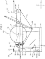
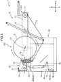
- Fig. 3 is a schematic view showing a state where the sheet S of the first roll R1 is pressed onto the outer peripheral surface of the second roll R2 in the joining mechanism 20.
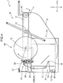
- Fig. 4 is a schematic view showing a state where the sheet S of the first roll R1 is cut in the joining mechanism 20.
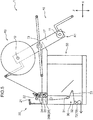
- Fig. 5 is a schematic view showing a state where the sheet S of the first roll R1 is wound up in the joining mechanism 20.
- the unit driving source 27 includes, for example, a servomotor, and the drive force thereof is transmitted to the joining unit 23 via a power transmission mechanism including a belt and a pulley. Owing to the transmitted drive force, it is possible to move the joining unit 23 forward to be closer to the second roll R2 at the splice position and backward to be away from the second roll R2.
- the pressing roller 24 has an axis extending in the Y direction, and is attached to the joining unit 23. Hence, the pressing roller 24 shifts forward and backward together with the joining unit 23 while kept in parallel to the axis of the second roll R2.
- This configuration achieves a joining operation of joining the sheets S via the adhesive H by causing the pressing roller 24 to press the intermediate portion of the sheet S run from the first roll R1 onto the outer peripheral surface of the second roll R2.
- the joining mechanism 20 performs the joining operation of joining the respective sheets S of the first roll R1 and the second roll R2 to each other by causing the pressing roller 24 to perform the pressing operation of pressing the sheet S run from the first roll R1 rotating in association with the rotation of the first support shaft 11 to the adhesive H provided on the outer peripheral surface of the second roll R2 rotating in association with the rotation of the second support shaft 12 (see Fig. 3 ).
- the cutter 25 has a cutter blade 25B rotatable about an axis extending in the Y direction, and a cutter driving source 25A ( Fig. 2 ) which generates a drive force to rotate the cutter blade 25B.
- the cutter 25 is also attached to the joining unit 23, and thus shifts forward and backward together with the joining unit 23.
- the cutter 25 can cut the sheet S run from the first roll R1 at an upstream position of the joining portion where the sheets S have been joined to each other after the joining operation (see Fig. 4 ).
- the first roll R1 is reversely rotated to wind up the portion of the sheet S that is upstream of the cutting position (see Fig. 5 ).
- the radius detector 21 includes, for example, a laser sensor. As shown in Fig. 1 , the radius detector 21 is fixedly held at a higher position than the joining unit 23 via a bracket 26 standing on the beam 53.
- the adhesive detector 22 includes, for example, a color sensor (a line sensor or an area sensor).
- the adhesive detector 22 is further attached to the joining unit 23, and thus shifts forward and backward together with the joining unit 23.
- the drive part 70 is arranged at a most downstream position in a sheet conveyance direction in the sheet supply apparatus 1.
- the drive part 70 includes a driving roller 72 having an axis extending in the Y direction so as to support the sheet S, and a roller driving source 71 ( Fig. 2 ) which generates a drive force to rotate the driving roller 72 around the axis at a predetermined speed.
- the roller driving source 71 includes, for example, a motor.
- a conveyance speed is regulated to supply the sheet S to the line in the downstream location at a predetermined conveyance speed by adjusting the rotational speed of the driving roller 72 via the output from the roller driving source 71.
- the rotational speed of the first support shaft 11 is regulated so that the sheet S is unwound from the first roll R1 at a predetermined running speed.
- the tension adjusting mechanism 30 is provided between the joining unit 23 and the driving roller 72 in the sheet conveyance direction.
- the tension adjusting mechanism 30 executes a feedback control via the controller 80 so that the sheet S is unwound from the first roll R1 at the predetermined running speed.
- the tension adjusting mechanism 30 has a pair of fixed rollers 31, 32, and a movable roller 33 which is disposed between the pair of fixed rollers 31, 32 and moved depending on a tension of the sheet S.
- the sheet S run from the first roll R1 can be supported on the fixed rollers 31, 32, and the movable roller 33.
- the movable roller 33 When the tension of the sheet S is lower than a predetermined set value, the movable roller 33 is moved to increase a path length of the sheet S. Conversely, when the tension of the sheet is higher than the set value, the movable roller 33 is moved to decrease the path length of the sheet S.
- the tension adjusting mechanism 30 further includes a position detection sensor 34 ( Fig. 2 ) for detecting the position of the movable roller 33.
- a result of the detection obtained by the position detection sensor 34 is sent to the controller 80.
- the controller 80 regulates the rotational speed of the first support shaft 11 based on the detection result. In other words, positional information of the movable roller 33 is fed back for the rotation control of the first support shaft 11. Owing to the feedback, the tension is changed to place the movable roller 33 at a predetermined setting position by adjusting the supply speed of the sheet S run from the first roll R1 by way of acceleration or deceleration. This consequently makes it possible to regulate the rotational speed of the first support shaft 11 so that the sheet S is unwound from the first roll R1 at the predetermined running speed.
- the controller 80 includes a CPU (Central Processing Unit), a RAM (Random Access Memory), a ROM (Read Only Memory) and the like in combination.
- the controller 80 controls the support mechanism 10 and the joining mechanism 20 when the residual length of the sheet S of the first roll R1 reaches a predetermined residual length or shorter in the state where the sheet S is supplied from the first roll R1 (supply roll).
- the controller 80 controls the support mechanism 10 and the joining mechanism 20 so that a target joining portion of the sheet S run from the first roll R1 is joined to the adhesive H on the outer peripheral surface of the second roll R2.
- the target joining portion of the sheet S of the first roll R1 represents a portion to be joined to the adhesive H on the second roll R2 where a residual length of the sheet S of the first roll R1 reaches a predetermined target residual wound length.
- the controller 80 includes a rotary member control section 81, a first shaft control section 82A, a second shaft control section 82B, a unit control section 83, a cutter control section 84, a roller control section 85, a radius determination section 86, an adhesive position determination section 87, a residual length calculation section 88, and a residual length monitoring section 89.
- the rotary member control section 81 controls rotation and stop of the motor constituting the rotary member driving source 18.
- the first shaft control section 82A controls rotation and stop of the motor constituting the first shaft driving source 19A.
- the second shaft control section 82B controls rotation and stop of the motor constituting the second shaft driving source 19B.
- the unit control section 83 controls drive and rotation of the servomotor constituting the unit driving source 27. Consequently, the joining unit 23 is controlled to move closer to or away from the second roll R2 at the splice position.
- the cutter control section 84 controls the drive of the cutter driving source 25A. Hence, the rotation of the cutter blade 25B of the cutter 25 is controlled.
- the roller control section 85 controls rotation and stop of the motor constituting the roller driving source 71. In this way, the rotation of the driving roller 72 is controlled.
- the radius determination section 86 determines radiuses of the second roll R2 at a plurality of locations in the rotational direction of the second roll R2 based on the detection result from the radius detector 21 in a state where the second roll R2 (the standby roll) is rotated in association with the rotation of the second support shaft 12 owing to the second shaft driving source 19B, and further determines a mean radius of the second roll R2 based on the determined radiuses.
- the adhesive position determination section 87 determines a circumferential position of the adhesive H on the outer peripheral surface of the second roll R2 (the standby roll) based on the detection result from the adhesive detector 22.
- the residual length calculation section 88 calculates the residual length of the sheet S of the first roll R1 in a state where the sheet S is unwound from the first roll R1 (the supply roll) rotating in association with the rotation of the first support shaft 11 at the predetermined running speed. Specifically, the residual length calculation section 88 calculates a radius of the first roll R1 based on the running speed of the sheet S of the first roll R1, and a rotational speed of the first support shaft 11. Furthermore, the residual length calculation section 88 calculates a sheet thickness of the sheet S unwound from the first roll R1 in accordance with a reduction in the radius of the first roll R1 for each rotation thereof. Moreover, the residual length calculation section 88 calculates the residual length of the sheet S of the first roll R1 based on the radius of the first roll R1 and the sheet thickness of the sheet S.
- the residual length monitoring section 89 monitors the residual length of the sheet S of the first roll R1 calculated by the residual length calculation section 88, and outputs a control instructive signal for instructing rotation control for each of the first support shaft 11 and the second support shaft 12 to the first shaft control section 82A and the second shaft control section 82B in accordance with the residual length of the sheet.
- the operation of the residual length monitoring section 89 will be described in detail later.
- the controller 80 executes controls described below in the ordinary operation where the sheet is supplied to the downstream location, and in the sheet joining.
- the controller 80 controls the first support shaft 11 and the drive part 70 to supply the sheet S of the first roll R1 (the supply roll) from the drive part 70 to the downstream location at the predetermined conveyance speed set for the line in the downstream location.
- the controller 80 controls the first support shaft 11 by using the feedback from the tension adjusting mechanism 30 so that the running speed of the sheet S unwound from the first roll R1 coincides with the supply speed of the sheet S from the drive part 70.
- the controller 80 controls the first support shaft 11, the second support shaft 12, and the joining mechanism 20 so that the target joining portion of the sheet S run from the first roll R1 is joined to the adhesive H on the outer peripheral surface of the second roll R2 by causing the pressing roller 24 in the joining mechanism 20 to perform the pressing operation, the residual length of the sheet of the first roll R1 reaching a predetermined target residual wound length at the target joining portion.
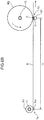
- Fig. 6A is a view schematically showing a state where the sheet S of the first roll R1 is unwound from the first roll R1.
- Fig. 6B is a view explaining a processing of controlling rotation of the second support shaft 12 to be executed by the controller. 80.
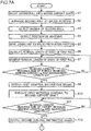
- Figs. 7A and 7B is a flowchart showing a sequence of the processing executed by the controller 80.
- a current sheet is supplied from the first roll R1 supported on the first support shaft 11, and a new second roll R2 is mounted onto the second support shaft 12, i.e., a case where the first roll R1 serves as the supply roll, and the second roll R2 serves as the standby roll.
- a sheet supply step is executed in the ordinary operation where the sheet S is supplied from the first roll R1 to the line in the downstream location prior to the execution of the sheet joining operation.
- the controller 80 controls the first support shaft 11 and the drive part 70 so that the sheet S is unwound from the first roll R1 at the predetermined running speed.
- the controller 80 calculates the radius of the first roll R1 based on the conveyance length of the sheet S in the line for each rotation of the first roll R1.
- a calculation mode for the radius of the first roll R1 is referred to as an "actual measurement mode".
- the controller 80 (the first shaft control section 82A) regulates the rotational speed of the first support shaft 11 based on the radius of the first roll R1 calculated in the actual measurement mode, and the detection result from the position detection sensor 34 concerning the position of the movable roller 33 in the tension adjusting mechanism 30.
- the controller 80 calculates the radius of the first roll R1 based on the conveyance length of the sheet S for each rotation of the first roll R1, and regulates the rotational speed of the first support shaft 11 based on the calculation result.
- a target residual wound length La and a management length Lb concerning the residual length of the sheet S of the first roll R1 are set in response to an operation of input performed by an operator to an operation part 90 (see Fig. 6A ).
- the target residual wound length La of the sheet S of the first roll R1 represents a target value of the residual length of the sheet S of the first roll R1 after the respective sheets S of the first roll R1 and the second roll R2 are joined to each other.
- the management length Lb of the sheet S of the first roll R1 is set at a combination of an adjusted length Lb1 and a peripheral speed regulating length Lb2.
- the peripheral speed regulating length Lb2 represents a conveyance length of the sheet S of the first roll R1 that is presumed to be supplied under a first rotation control executed by the second shaft control section 82B to the second support shaft 12, which will be described in detail later.
- the rotational speed of the second support shaft 12 is regulated so that the peripheral speed of the second roll R2 coincides with the running speed of the sheet S of the first roll R1 under the first rotation control executed by the second shaft control section 82B.
- the adjusted length Lb1 represents a conveyance length of the sheet S of the first roll R1 that is presumed to be supplied under a second rotation control executed by the second shaft control section 82B to the second support shaft 12, which will be described in detail later.
- the rotational speed of the second support shaft 12 is regulated by way of acceleration or deceleration under the second rotation control executed by the second shaft control section 82B.
- the management length Lb that is the combination of the adjusted length Lb1 and the peripheral speed regulating length Lb2 is set at, for example, 75 m.
- the adjusted length Lb1 is set at, for example, 10 m to 50 m, specifically, at 25.4 m.
- the controller 80 controls the rotation of the rotary member 17 so that the second support shaft 12 is moved to a mount position opposite to a splice position where the second support shaft 12 moves closer to the joining mechanism 20 (step S1). In this manner, the operator mounts the second roll R2 onto the second support shaft 12 disposed at the mount position.
- the controller 80 controls the rotation of the rotary member 17 so that the second support shaft 12 is moved to the splice position where the second support shaft 12 is closer to the joining mechanism 20 (step S2).
- the controller 80 (the second shaft control section 82B) rotates the second roll R2 by rotating the second support shaft 12.
- the radius detector 21 starts to detect the radiuses of the second roll R2 (step S3).
- the controller 80 (the second shaft control section 82B) stops the rotation of the second support shaft 12.
- the controller 80 (the unit control section 83) causes the joining unit 23 mounted with the adhesive detector 22 to move closer to a position at a predetermined distance from the maximal radius. Thereafter, the controller 80 (the second shaft control section 82B) rotates the second roll R2 by rotating the second support shaft 12. In this state, the adhesive detector 22 detects the position of the adhesive H on the outer peripheral surface of the second roll R2 (step S4).
- the controller 80 determines the position of the adhesive H on the outer peripheral surface of the second roll R2 in the circumferential direction of the second roll R2, that is, determines the position in the rotational direction with respect to the second support shaft 12, based on the detection result from the adhesive detector 22.
- the controller 80 (the second shaft control section 82B) stops the rotation of the second support shaft 12 so that the adhesive H moves to a predetermined position in the rotational direction of the second roll R2 based on the determined position of the adhesive H.
- the controller 80 moves the joining unit 23 to a splice preparation position (step S5).
- the splice preparation position is set in such a manner that the pressing roller 24 is kept away from the second roll R2 without coming into contact therewith irrespective of difference in the radiuses of the second roll R2 in the rotational direction thereof.
- the controller 80 calculates the residual length of the sheet S of the first roll R1 in a state where the sheet S is unwound from the first roll R1 at a predetermined running speed (residual length calculation step S6).
- the controller 80 calculates the residual length of the sheet S of the first roll R1 based on the radius of the first roll R1 and the sheet thickness each changing in accordance with the supply of the sheet S from the first roll R1, as described above.
- the calculation of the residual length of the sheet S of the first roll R1 is continuously executed for each rotation of the first support shaft 11.
- the controller 80 (the residual length monitoring section 89) monitors the residual length of the sheet S of the first roll R1 calculated for each rotation of the first support shaft 11 (residual length monitoring step S7).
- the monitoring of the residual length of the sheet S of the first roll R1 is also continuously executed for each rotation of the first support shaft 11 in the same manner as the calculation of the sheet residual length.
- the controller 80 determines whether the residual length of the sheet S of the first roll R1 reaches a first watch residual length (the target residual wound length La + the management length Lb) that is a sum of the management length Lb and the target residual wound length La (step S8). When determining that the residual length reaches the first watch residual length, the controller 80 (the residual length monitoring section 89) outputs a first control instructive signal for instructing rotation control for the second support shaft 12 (step S9, see Fig. 6A ).
- the controller 80 executes the first rotation control to the second support shaft 12 by starting the rotation of the second support shaft 12 supporting the second roll R2 (first rotational speed regulation step S10).
- the controller 80 starts the rotation of the second support shaft 12, and regulates the rotational speed of the second support shaft 12 in accordance with the mean radius of the second roll R2 based on the detection result from the radius detector 21 so that the peripheral speed of the second roll R2 coincides with the running speed of the sheet S of the first roll R1 under the first rotation control.
- the controller 80 After outputting the first control instructive signal, the controller 80 (the residual length monitoring section 89) determines whether the residual length of the sheet S of the first roll R1 reaches a second watch residual length (the target residual wound length La + the adjusted length Lb1) that is a sum of the adjusted length Lb1 (a predetermined length) and the target residual wound length La (step S11). When determining that the residual length reaches the second watch residual length, the controller 80 (the residual length monitoring section 89) outputs a second control instructive signal for instructing the rotation control for each of the first support shaft 11 and the second support shaft 12 (step S12, see Fig. 6A ).
- Steps S13, S14, and S15 are executed after the second control instructive signal is output in the step S12.
- the controller 80 shifts the setting of the calculation mode for the radius of the first roll R1 from the "actual measurement mode” to a "presumption mode", and regulates the rotational speed of the first support shaft 11 based on a presumed radius value calculated in the "presumption mode” so that the running speed of the sheet S from the first roll R1 is constant.
- the "presumption mode” represents a radius calculation mode where a radius of the first roll R1 that changes each rotation of the first roll R1 is calculated and presumed based on its change caused by the supply of the sheet S from R1, and a presumed radius value obtained by the presumption is set as a radius for regulating the rotational speed of the first support shaft, the change caused by the supply of the sheet S having been referred to in the residual length calculation step S6 and the residual length monitoring step S7 of calculating the residual length of the sheet of the first roll R1.
- the controller 80 controls, in the step S13, the rotation of the first support shaft 11 by shifting from the control: using the radius of the first roll R1 (i.e., the radius based on the conveyance length of the sheet S for each rotation of the first roll R1) calculated in the "actual measurement mode”; and based on the detection result from the position detection sensor 34 to the control using the presumed radius value of the first roll R1 calculated in the "presumption mode”.
- the controller 80 (the first shaft control section 82A) then regulates the rotational speed of the first support shaft 11 so that the running speed of the sheet S from the first roll R1 is constant by using the presumed radius value calculated in the "presumption mode".
- the rotational speed of the first support shaft 11 is regulated based on the presumed radius value of the first roll R1 calculated in the "presumption mode" during a period of time from the step S13 executed after the second control instructive signal is output to the step S19 in which the joining mechanism 20 performs the joining operation.
- the feedback control of the tension adjusting mechanism 30 is executed for the control of regulating the rotational speed of the first support shaft 11 based on the presumed radius value of the first roll R1 calculated in the "presumption mode” in the same manner as the regulation in the "actual calculation mode".
- the feedback control of the tension adjusting mechanism 30 achieves a smaller erroneous difference between the running speed of the sheet S from the first roll R1 and the supply speed of the sheet S at the drive part 70.
- the controller 80 executes preparation for operating the joining unit 23. Specifically, the controller 80 (the unit control section 83) sets a time for moving the joining unit 23 so that the pressing roller 24 performs the pressing operation. Additionally, the controller 80 (the cutter control section 84) sets a time for controlling the cutter blade 25B of the cutter 25 to rotate at a time when the pressing roller 24 performs the pressing operation.
- the controller 80 executes the second rotation control to the second support shaft 12 supporting the second roll R2 subsequent to the first rotation control (second rotation speed regulating step).
- the controller 80 regulates the rotational speed of the second support shaft 12 by way of acceleration or deceleration so that the adhesive H on the outer peripheral surface of the second roll R2 arrives at a pressing position Tp where the pressing roller 24 in the joining mechanism 20 performs the pressing operation when a target joining portion Tr of the sheet S run from the first roll R1 meets the pressing position Tp, and the peripheral speed of the second roll R2 coincides with the running speed of the sheet S of the first roll R1, the residual length of the sheet S of the first roll R1 reaching the target residual wound length La at the target joining portion Tr. (see Fig. 6 ).
- a target residual wound length position Tm where the residual length of the sheet S of the first roll R1 reaches the target residual wound length La agrees with an unwinding start position Ts of the first roll R1.
- the target joining portion Tr of the sheet S of the first roll R1 is downstream of the target residual wound length position Tm at a distance of a predetermined reference length LL.
- the reference length LL corresponds to a path length from the unwinding start position Ts of the first roll R1 to the pressing position Tp, and is substantially uniform.
- the adhesive H locates at any circumferential position of the second roll R2 on the outer peripheral surface thereof.
- the circumferential position of the adhesive H is understood from its position in the rotational direction with respect to the second support shaft 12 as detected by the adhesive detector 22.
- the rotational speed of the second support shaft 12 is maintained in the case where the adhesive H in the rotational direction of the second roll R2 arrives at the pressing position Tp when the target joining portion Tr of the sheet S of the first roll R1 meets the pressing position Tp in the state where the peripheral speed of the second roll R2 coincides with the running speed of the sheet S of the first roll R1.
- the rotational speed of the second support shaft 12 is restored and maintained such that the peripheral speed of the second support shaft 12 coincides with the running speed of the sheet S of the first roll R1 when the adhesive H arrives at the pressing position Tp and the target joining portion Tr of the sheet S of the first roll R1 meets the pressing position Tp owing to the acceleration or deceleration.
- the rotational speed regulation by way of the acceleration or deceleration may be executed for a plurality of times until the target joining portion Tr meets the pressing position Tp.
- the controller 80 moves the joining unit 23 to cause the pressing roller 24 to perform the pressing operation when the target joining portion Tr of the sheet S of the first roll R1 meets the pressing position Tp and the adhesive H on the outer peripheral surface of the second roll R2 arrives at the pressing position Tp at the same time (joining processing step S16). Consequently, the target joining portion Tr of the sheet S of the first roll R1 is joined to the adhesive H on the outer peripheral surface of the second roll R2.
- the controller 80 (the cutter control section 84) further rotates the cutter blade 25B of the cutter 25 at a time when the pressing roller 24 performs the pressing operation (step S17), thereby cutting the sheet S from the first roll R1. After the sheet S is cut from the first roll R1, supply of the sheet S from the second roll R2 is started. At this time, the controller 80 shifts the roll setting (step S18). Specifically, the controller 80 sets a new roll mounted onto the first support shaft 11 as a next standby roll in place of the first roll R1 whose sheet has been cut, and sets the second roll R2 from which the sheet supply is started as a next supply roll.
- the controller 80 executes a post-operation after the joining operation (step S19). Specifically, the controller 80 (the unit control section 83) moves the joining unit 23 backward. The controller 80 (the first shaft control section 82A) then winds up a portion of the sheet S that is upstream of the cutting position by reversely rotating the first roll R1.
- the controller 80 sets the calculation mode for the radius of the second roll R2 serving as the supply roll at the "actual measurement mode" (step S20).
- the controller 80 calculates the radius of the second roll R2 based on a conveyance length of the sheet S in the line for each rotation of the second roll R2.
- the controller 80 regulates the rotational speed of the second support shaft 12 based on the radius of the second roll R2 calculated in the actual measurement mode and the detection result from the position detection sensor 34 concerning the position of the movable roller 33 in the tension adjusting mechanism 30.
- the sheet joining operation is restored to the ordinary operation (step S21).
- the first shaft control section 82A controls the rotation of the first support shaft 11 supporting the first roll or supply roll R1
- the second shaft control section 82B controls the rotation of the second support shaft 12 supporting the second roll or standby roll R2.
- the first shaft control section 82A controls the rotation of the first support shaft 11 so that the sheet S is unwound from the first roll R1 at the predetermined running speed.
- the second shaft control section 82B executes the first rotation control of regulating the rotational speed of the second support shaft 12 so that the peripheral speed of the second roll R2 coincides with the running speed of the sheet S of the first roll R1, and thereafter executes the second rotation control subsequent to the first rotation control.
- the second shaft control section 82B regulates the rotational speed of the second support shaft 12 by way of acceleration or deceleration under the second rotation control subsequent to the first rotation control. This makes it possible to regulate the rotational speed of the second support shaft 12 so that the adhesive H on the outer peripheral surface of the second roll R2 arrives at the pressing position Tp when the target joining portion Tr of the sheet S of the first roll R1 meets the pressing position Tp, the residual length of the sheet S of the first roll R1 reaching the predetermined target residual wound length La at the target joining portion Tr.
- the respective sheets of the first roll R1 and the second roll R2 can be joined to each other in such a manner that the target joining portion Tr of the sheet S of the first roll R1 is joined to the adhesive H on the outer peripheral surface of the second roll R2.
- the residual length of the sheet S of the first roll R1 can reach the predetermined target residual wound length La in the joining of the sheets to each other via the adhesive H on the outer peripheral surface of the second roll R2.
- the first shaft control section 82A regulates the rotational speed of the first support shaft 11 supporting the first roll R1 (step S13), and the second shaft control section 82B executes at least the second rotation control among the first rotation control and the second rotation control to the second support shaft 12 supporting the second roll R2 (step S15).
- execution of the rotation control for the first support shaft 11 based on the radius of the first roll R1 calculated in the "actual measurement mode" with reference to the conveyance length of the sheet S for each rotation of the first roll R1 may cause frequent fluctuation in the running speed of the sheet S for each rotation due to the acceleration or deceleration.
- the target joining portion Tr of the sheet S of the first roll R1 cannot always meet the pressing position Tp at a constant time.
- there is a concern that a difference may occur between the time when the target joining portion Tr of the sheet S of the first roll R1 meets the pressing position Tp and the time when the adhesive H on the outer peripheral surface of the second roll R2 arrives at the pressing position Tp, which results in unreliable joining at the target joining portion Tr.
- the first shaft control section 82A regulates, based on the presumed radius value of the first roll R1 that is calculated in the "presumption mode" and changes in accordance with the supply of the sheet S, the rotational speed of the first support shaft 11 in response to the second control instructive signal output from the residual length monitoring section 89 so that the running speed of the sheet S from the first roll R1 is constant during a period of time until the pressing roller 24 in the joining mechanism 20 performs the pressing operation after the residual length monitoring section 89 outputs the second instructive signal (step S13).
- the regulation contributes to suppression of fluctuation in the time when the target joining portion Tr of the sheet S of the first roll R1 meets the pressing position Tp.
- the second shaft control section 82B can regulate the rotational speed of the second support shaft 12 in response to the second control instructive signal output from the residual length monitoring section 89 so that the adhesive H on the outer peripheral surface of the second roll R2 arrives at the pressing position Tp when the target joining portion Tr of the sheet S of the first roll R1 meets the pressing position Tp (step S15). Accordingly, the target joining portion Tr of the sheet S of the first roll R1 can be reliably joined to the adhesive H on the outer peripheral surface of the second roll R2.
- the second shaft control section 82B executes the first rotation control by starting the rotation of the second support shaft 12 after the first control instructive signal is output and before the second control instructive signal is output (step S10), and executes the second rotation control subsequent to the first rotation control after the second control instructive signal is output (step S15).
- the second shaft control section 82B executes the first rotation control by starting the rotation of the second support shaft 12 before the residual length monitoring section 89 outputs the second control instruction signal. This establishes the state where the rotational speed of the second support shaft 12 is regulated so that the peripheral speed of the second roll R2 coincides with the running speed of the sheet S of the first roll R1 before the second control instructive signal is output. In this case, it is sufficient to regulate the rotational speed of the second support shaft 12 based on the position of the adhesive H in the rotational direction of the second roll R2 under the second rotation control executed by the second shaft control section 82B subsequent to the first rotation control after the second instructive signal is output.
- the adhesive H on the outer peripheral surface of the second roll R2 can more accurately arrive at the pressing position Tp when the target joining portion Tr of the sheet S of the first roll R1 meets the pressing position Tp under the second rotation control executed by the second shaft control section 82B. Accordingly, the residual length of the sheet S of the first roll R1 can more reliably reach the predetermined target residual wound length La in the joining of the sheets to each other via the adhesive H on the outer peripheral surface of the second roll R2.
- the second shaft control section 82B controls the rotation of the second support shaft 12 supporting the second or standby roll R2 by executing the first rotation control before the second instructive signal is output and executing the second rotation control after the second control instructive signal is output, but should not be limited to this configuration.
- the second shaft control section 82B may be configured to stop the rotation of the second support shaft 12 supporting the second or standby roll R2 before the residual length monitoring section 89 outputs the second control instructive signal, and execute both the first rotation control and the second rotation control after the second control instructive signal is output. Under the first rotation control, the second shaft control section 82B regulates at least one of a rotation start time and a rotational acceleration so that the adhesive H moves to a predetermined position in the rotational direction of the second roll R2, when the peripheral speed of the second roll R2 reaches the running speed of the sheet S of the first roll R1 by starting the rotation of the second support shaft 12.
- the second shaft control section 82B regulates the rotational speed of the second support shaft 12 by way of acceleration or deceleration, if necessary, so that the adhesive H at the predetermined position arrives at the pressing position Tp when the target joining portion Tr of the sheet S of the first roll R1 meets the pressing position Tp under the second rotation control subsequent to the first rotation control.
- the rotation of the second support shaft 12 is stopped before the residual length monitoring section 89 outputs the second control instructive signal.
- the adhesive H locates at a position at a predetermined angle in the rotational direction of the second roll R2 when the second control instructive signal is output.
- the position of the adhesive H in the rotational direction of the second roll R2 is determined when the rotation control for the second support shaft 12 is started.
- the predetermined position can be set in such a manner that, for example, a distance from the predetermined position to the pressing position Tp equals to a distance between the target joining portion Tr of the sheet S of the first roll R1 and the pressing position Tp at the finish of the first rotation control.
- the adhesive H at the predetermined position can consequently arrive at the pressing position Tp or move closest thereto only with a tolerant deviation when the target joining portion Tr of the sheet S of the first roll R1 meets the pressing position Tp under the second rotation control executed subsequent to the first rotation control. Accordingly, it is sufficient to regulate the rotational speed of the second support shaft 12 by a small amount. This shortens the time required to regulate the rotational speed of the second support shaft 12 under the second rotation control. Further, the adhesive H on the outer peripheral surface of the second roll R2 can more accurately arrive at the pressing position Tp when the target joining portion Tr of the sheet S of the first roll R1 meets the pressing position Tp.
- the second shaft control section 82B may be configured to regulate the rotational speed of the second support shaft 12 so that the peripheral speed of the second roll R2 reaches the running speed of the sheet S of the first roll R1 and the adhesive H on the outer peripheral surface of the second roll R2 arrives at the pressing position Tp when the target joining portion Tr of the sheet S of the first roll R1 meets the pressing position Tp.
- the second shaft control section 82B adjusts at least one of a rotation start time and a rotational acceleration of the second support shaft 12.
- the peripheral speed of the second roll R2 coincides with the running speed of the sheet S of the first roll R1 and the adhesive H on the outer peripheral surface of the second roll R2 arrives at the pressing position Tp when the target joining portion Tr of the sheet S of the first roll R1 meets the pressing position Tp.
- the joining mechanism 20 can more rapidly perform the joining operation of joining the respective sheets of the first roll R1 and the second roll R2 to each other. Consequently, it is possible to expedite sheet supply shift from the first roll R1 to the second roll R2.
- the rotary member 17 includes the first support shaft 11 and the second support shaft 12.
- the rotary member 17 may include three or more support shafts for rotatably supporting the rollers at their respective center positions.
- the joining unit 23 is moved in the X direction (lateral direction) to thereby cause the pressing roller 24 to press the sheet S of the first roll R1 onto the outer peripheral surface of the second roll R2 in the joining operation by the joining mechanism 20.
- the joining unit 23 should not be limited to this configuration.
- the joining unit 23 may be moved in the Z direction (vertical direction) in the joining operation by the joining mechanism 20.
- Described in the embodiment is the configuration independently including the radius detector 21 for detecting the radius of the second roll or standby roll R2, and the adhesive detector 22 for detecting the position of the adhesive H on the outer peripheral surface of the second roll R2.
- a single detector may be adopted to detect the radius of the second roll R2 and the position of the adhesive H.
- the above-described embodiment mainly includes the invention having the following configurations.
- a sheet supply apparatus is an apparatus for sequentially unwinding a sheet from a first roll of sheet and a second roll of sheet for sheet supply.
- the sheet supply apparatus includes: a first support shaft which rotatably supports the first roll at a center position thereof; a second support shaft which rotatably supports the second roll at a center position thereof; a joining mechanism which joins the respective sheets of the first roll and the second roll to each other by a pressing operation of pressing the sheet run from the first roll rotating in association with rotation of the first support shaft to an adhesive provided on an outer peripheral surface of the second roll rotating in association with rotation of the second support shaft; and a controller which controls the rotation of each of the first support shaft and the second support shaft so that a target joining portion of the sheet run from the first roll is joined to the adhesive on the outer peripheral surface of the second roll by the pressing operation of the joining mechanism when a residual length of the sheet of the first roll reaches a predetermined target residual wound length.
- the controller includes: a residual length calculation section which calculates a radius of the first roll that changes in accordance with the sheet supply from the first roll, and calculates a residual length of the sheet of the first roll from a result of the radius calculation; a residual length monitoring section which monitors the residual length of the sheet of the first roll that has been calculated by the residual calculation section, and outputs a control instructive signal when the residual length of the sheet reaches a watch length that is a sum of a predetermined length and the target residual wound length; a first shaft control section which controls the rotation of the first support shaft in response to the control instructive signal so that the sheet is unwound from the first roll for the sheet supply at a predetermined running speed; and a second shaft control section which controls the rotation of the second support shaft in response to the control instructive signal, the second shaft control section being configured to regulate a rotational speed of the second support shaft so that a peripheral speed of the second roll coincides with the running speed of the sheet of the first roll, and the adhesive on the outer peripheral surface of the second roll
- the second shaft control section regulates the rotational speed of the second support shaft in response to the control instructive signal output from the residual length monitoring section so that the adhesive on the outer peripheral surface of the second roll arrives at the pressing position when the target joining portion of the sheet of the first roll meets the pressing position, the residual length of the sheet of the first roll reaching a predetermined target residual wound length at the target joining portion.
- the second shaft control section may be configured to execute: a first rotation control of regulating the rotational speed of the second support shaft so that the peripheral speed of the second roll coincides with the running speed of the sheet of the first roll; and a second rotation control of regulating the rotational speed of the second support shaft so that the adhesive on the outer peripheral surface of the second roll arrives at the pressing position when the target joining portion of the sheet of the first roll meets the pressing position, and the peripheral speed of the second roll coincides with the running speed of the sheet of the first roll, after the first rotation control.
- the second shaft control section executes the first rotation control of regulating the rotational speed of the second support shaft so that the peripheral speed of the second roll coincides with the running speed of the sheet of the first roll, and thereafter executes the second rotation control. Accordingly, it is possible to regulate the rotational speed of the second support shaft so that the adhesive on the outer peripheral surface of the second roll arrives at the pressing position when the target joining portion of the first roll meets the pressing position, and the peripheral speed of the second roll coincides with the running speed of the sheet of the first roll.
- the second shaft control section may be configured to execute the first rotation control by starting the rotation of the second support shaft before the residual length monitoring section outputs the control instructive signal, and executes the second rotation control subsequent to the first rotation control after the residual length monitoring section outputs the control instructive signal.
- the second shaft control section executes the first rotation control by starting the rotation of the second support shaft before the residual length monitoring section outputs the control instructive signal. This establishes the state where the rotational speed of the second support shaft is regulated so that the peripheral speed of the second roll coincides with the running speed of the sheet of the first roll before the control instructive signal is output. In this case, it is sufficient to regulate the rotational speed of the second support shaft based on the position of the adhesive in the rotational direction of the second roll under the second rotation control executed by the second shaft control section subsequent to the first rotation control after the control instructive signal is output. Therefore, it is possible to expedite the time to finish the regulation of the rotational speed of the second support shaft under the second rotation control.
- the adhesive on the outer peripheral surface of the second roll can more accurately arrive at the pressing position when the target joining portion of the sheet of the first roll meets the pressing position under the second rotation control executed by the second shaft control section. Accordingly, the residual length of the sheet of the first roll can more reliably reach the predetermined target residual wound length in the joining of the sheets to each other via the adhesive on the outer peripheral surface of the second roll.
- the second shaft control section may be configured to stop the rotation of the second support shaft before the residual length monitoring section outputs the control instructive signal, and execute the first rotation control and the second rotation control after the residual length monitoring section outputs the control instructive signal.
- the second shaft control section adjusts at least one of a rotation start time and a rotational acceleration of the second support shaft so that the adhesive moves to a predetermined position in a rotational direction of the second roll, when the peripheral speed of the second roll reaches the running speed of the sheet of the first roll by starting the rotation of the second support shaft under the first rotation control, and regulates the rotational speed of the second support shaft by way of acceleration or deceleration so that the adhesive at the predetermined position arrives at the pressing position when the target joining portion of the sheet of the first roll meets the pressing position under the second rotation control subsequent to the first rotation control.
- the rotation of the second support shaft is stopped before the residual length monitoring section outputs the second control instructive signal.
- the adhesive locates at a position at a predetermined angle in the rotational direction of the second roll when the control instructive signal is output.
- the position of the adhesive in the rotational direction of the second roll is determined when the rotation control for the second support shaft is started.
- the second shaft control section may be configured to regulate the rotational speed of the second support shaft so that the peripheral speed of the second roll reaches the running speed of the sheet of the first roll and the adhesive on the outer peripheral surface of the second roll arrives at the pressing position when the target joining portion of the sheet of the first roll meets the pressing position.
- the peripheral speed of the second roll coincides with the running speed of the sheet of the first roll, and the adhesive on the outer peripheral surface of the second roll arrives at the pressing position when the target joining portion of the sheet of the first roll meets the pressing position.
- the joining mechanism can more rapidly perform the joining operation of joining the respective sheets of the first roll and the second roll to each other. Consequently, it is possible to expedite the sheet supply shift from the first roll to the second roll.
- the first shaft control section may be configured to shift the control for the rotation of the first support shaft in response to the control instructive signal from a control using a sheet conveyance length by each rotation of the first roll to a control using the radius of the first roll which the residual length calculation section refers to when the residual length calculation section calculates the residual length of the sheet of the first roll, and regulate the rotational speed of the first support shaft based on a presumed radius value calculated on a change in the radius of the first roll so that the running speed of the sheet from the first roll is constant.
- Execution of the rotation control for the first support shaft based on the conveyance length of the sheet for each rotation of the first roll may cause frequent fluctuation in the running speed of the sheet for each rotation due to the acceleration or deceleration.
- the target joining portion Tr of the sheet S of the first roll R1 cannot always meet the pressing position Tp at a constant time.
- a difference may occur between the time when the target joining portion of the sheet of the first roll meets the pressing position and the time when the adhesive on the outer peripheral surface of the second roll arrives at the pressing position, which results in unreliable joining at the target joining portion.
- the first shaft control section controls the rotation of the first support shaft in response to the control instructive signal output from the residual length monitoring section by shifting from the control using the conveyance length of the sheet for each rotation of the first roll to the control using the presumed radius value obtained by calculating and presuming the radius of the first roll that changes in accordance with the supply of the sheet.
- the first shaft control section then regulates the rotational speed of the first support shaft so that the running speed of the sheet from the first roll is constant based on the presumed radius value of the first roll that changes in accordance with the supply of the sheet.
- the regulation contributes to suppression of fluctuation in the time when the target joining portion of the sheet of the first roll meets the pressing position. Accordingly, the target joining portion of the sheet of the first roll can be reliably joined to the adhesive on the outer peripheral surface of the second roll.
- a sheet supply method is a sheet supply method for sequentially unwinding a sheet from a first roll of sheet and a second roll of sheet for sheet supply by using a sheet supply apparatus including: a first support shaft which rotatably supports the first roll of sheet at a center position thereof; a second support shaft which rotatably supports the second roll of sheet at a center position thereof; and a joining mechanism which joins the respective sheets of the first roll and the second roll to each other by a pressing operation of pressing the sheet run from the first roll to an adhesive provided on an outer peripheral surface of the second roll.
- the sheet supply method includes: a sheet supply step of unwinding the sheet from the first roll at a predetermined running speed by rotating the first support shaft for sheet supply; a rotational speed regulation step of regulating a rotational speed of the second support shaft so that a peripheral speed of the second roll coincides with the running speed of the sheet of the first roll, and the adhesive on the outer peripheral surface of the second roll arrives at a pressing position where the pressing operation is performed by the joining mechanism when a target joining portion of the sheet unwound from the first roll meets the pressing position, a residual length of the sheet of the first roll reaching a predetermined target residual wound length at the target joining portion; and a joining step of causing the joining mechanism to perform the pressing operation so that the target joining portion of the sheet of the first roll is joined to the adhesive on the outer peripheral surface of the second roll.
- the first support shaft is rotated to unwind the sheet from the first roll at the predetermined running speed.
- the rotational speed of the second support shaft supporting the second roll is regulated in the rotational speed regulation step.
- the rotational speed of the second support shaft is regulated so that the peripheral speed of the second roll coincides with the running speed of the sheet of the first roll, and the adhesive on the outer peripheral surface of the second roll arrives at the pressing position when the target joining portion of the sheet of the first roll meets the pressing position.
- the respective sheets of the first roll and the second roll can be joined to each other in such a manner that the target joining portion of the sheet of the first roll is joined to the adhesive on the outer peripheral surface of the second roll.
- the residual length of the sheet of the first roll can reach the predetermined target residual wound length in the joining of the sheets to each other via the adhesive on the outer peripheral surface of the second roll.
- the present invention makes it possible to lead a residual length of a sheet of a first roll to a predetermined target residual wound length in joining of the sheets of the first roll and a second roll to each other via an adhesive on outer peripheral surface of the second roll.
Landscapes
- Replacement Of Web Rolls (AREA)
Abstract
Description
- The present invention relates to a sheet supply apparatus and a sheet supply method for continuously supplying a sheet from a roll of sheet.
- There have been conventionally known sheet supply apparatus for sequentially unwinding a sheet from a first roll of sheet and a second roll of sheet for sheet supply (for example, see Patent Literature 1). This sort of sheet supply apparatus includes a joining mechanism for joining the sheet of the first roll (a supply roll) in a supply state of supplying the sheet to the sheet of the second roll (a standby roll) in a standby state of suspending the supply of the sheet when a residual length of the sheet of the first roll reaches a predetermined residual length or shorter.
- When the residual length of the sheet of the first roll reaches the predetermined length or shorter, an instructive signal instructing the joining mechanism to operate is output. In response, the joining mechanism joins the respective sheets of the first and second rolls to each other by a pressing operation of pressing the sheet of the first roll to an adhesive provided on an outer peripheral surface of the second roll in a state where a support shaft of the second roll rotates so that a peripheral speed of the second roll coincides with a running speed of the sheet run from the first roll.
- As described above, the instructive signal is output for the joining operation when the residual length of the sheet of the first roll reaches the predetermined residual length or shorter. Here, the adhesive on the outer peripheral surface of the second roll does not always arrive at a pressing position where the joining mechanism performs the pressing operation at a constant time. Therefore, a period of elapsed time until the joining mechanism performs the pressing operation after the instructive signal is output is variable, and thus the length of the sheet unwound from the first roll during the period of elapsed time is not uniform. As a result, the residual length of the sheet of the first roll becomes variable in the joining of the sheets via the adhesive. To avoid the variable residual length, it is necessary to output the instructive signal while maintaining a maximal supply length of the sheet, and hence the residual length is always wastefully excessive. Concisely, the conventional sheet supply apparatus has a problem that it is difficult to lead the residual length of the sheet of the first roll to a predetermined target residual wound length when joining the sheets to each other via the adhesive.
- Patent Literature 1: Registered Japanese Utility-Model publication No.
2568743 - The present invention has been accomplished in view of the aforementioned problem, and an object of the present invention is to provide a sheet supply apparatus and a sheet supply method for leading a residual length of a sheet of a first roll to a predetermined target residual wound length when joining the sheet of the first roll and a sheet of a second roll to each other via an adhesive on an outer peripheral surface of the second roll.
- A sheet supply apparatus according to one aspect of the present invention is a sheet supply apparatus for sequentially unwinding a sheet from a first roll of sheet and a second roll of sheet for sheet supply. The sheet supply apparatus includes: a first support shaft which rotatably supports the first roll at a center position thereof; a second support shaft which rotatably supports the second roll at a center position thereof; a joining mechanism which joins the respective sheets of the first roll and the second roll to each other by a pressing operation of pressing the sheet run from the first roll rotating in association with rotation of the first support shaft to an adhesive provided on an outer peripheral surface of the second roll rotating in association with rotation of the second support shaft; and a controller which controls the rotation of each of the first support shaft and the second support shaft so that a target joining portion of the sheet run from the first roll is joined to the adhesive on the outer peripheral surface of the second roll owing to the pressing operation by the joining mechanism when a residual length of the sheet of the first roll reaches a predetermined target residual wound length. The controller includes: a residual length calculation section which calculates a radius of the first roll that changes in accordance with the sheet supply from the first roll, and calculates a residual length of the sheet of the first roll from a result of the radius calculation; a residual length monitoring section which monitors the residual length of the sheet of the first roll that has been calculated by the residual calculation section, and outputs a control instructive signal when the residual length of the sheet reaches a watch length that is a sum of a predetermined length and the target residual wound length; a first shaft control section which controls the rotation of the first support shaft in response to the control instructive signal so that the sheet is unwound from the first roll for the sheet supply at a predetermined running speed; and a second shaft control section which controls the rotation of the second support shaft in response to the control instructive signal. The second shaft control section is configured to regulate a rotational speed of the second support shaft so that a peripheral speed of the second roll coincides with the running speed of the sheet of the first roll, and the adhesive on the outer peripheral surface of the second roll arrives at a pressing position where the joining mechanism performs the pressing operation when the target joining portion of the sheet of the first roll meets the pressing position.
- A sheet supply method according to another aspect of the present invention is a sheet supply method for sequentially unwinding a sheet from a first roll of sheet and a second roll of sheet for sheet supply by using a sheet supply apparatus including: a first support shaft which rotatably supports the first roll of sheet at a center position thereof; a second support shaft which rotatably supports the second roll of sheet at a center position thereof; and a joining mechanism which joins the respective sheets of the first roll and the second roll to each other by a pressing operation of pressing the sheet run from the first roll to an adhesive provided on an outer peripheral surface of the second roll. The sheet supply method includes: a sheet supply step of unwinding the sheet from the first roll at a predetermined running speed by rotating the first support shaft for sheet supply; a rotational speed regulation step of regulating a rotational speed of the second support shaft so that a peripheral speed of the second roll coincides with the running speed of the sheet of the first roll and the adhesive on the outer peripheral surface of the second roll arrives at a pressing position where the pressing operation is performed by the joining mechanism when a target joining portion of the sheet unwound from the first roll meets the pressing position, a residual length of the sheet of the first roll reaching a predetermined target residual wound length at the target joining portion; and a joining step of causing the joining mechanism to perform the pressing operation so that the target joining portion of the sheet of the first roll is joined to the adhesive on the outer peripheral surface of the second roll.
- According to the present invention, it is possible to lead a residual length of a sheet of a first roll to a predetermined target residual wound length when joining respective sheets of the first roll and a second roll to each other via an adhesive on an outer peripheral surface of the second roll.
- The object, features, and advantages of the present invention will be further clarified by the following detailed description and the accompanying drawings.
-
-
Fig. 1 is a partial cross-sectional front view schematically showing a configuration of a sheet supply apparatus according to an embodiment of the present invention. -
Fig. 2 is a block diagram showing an electrical configuration of a controller which controls operations of the sheet supply apparatus. -
Fig. 3 is a schematic view showing a state where a sheet of a first roll is pressed onto an outer peripheral surface of a second roll in a joining mechanism provided in the sheet supply apparatus. -
Fig. 4 is a schematic view showing a state where the sheet of the first roll is cut in the joining mechanism. -
Fig. 5 is a schematic view showing a state where the sheet of the first roll is wound up in the joining mechanism. -
Fig. 6A is a view schematically showing a state where the sheet of the first roll is unwound from the first roll. -
Fig. 6B is a view explaining a processing of controlling rotation of a second support shaft to be executed by the controller. -
Fig. 7A is a flowchart showing a sequence of the processing executed by the controller. -
Fig. 7B is a flowchart showing another sequence of the processing executed by the controller. - Hereinafter, a sheet supply apparatus and a sheet supply method according to an embodiment of the present invention will be described with reference to the accompanying drawings. It should be noted that the following embodiment will be described as examples without limiting the technical scope of the present invention.
-
Fig. 1 is a partial cross-sectional front view of asheet supply apparatus 1.Fig. 2 is a block diagram showing an electrical configuration of acontroller 80 which controls operations of thesheet supply apparatus 1. Hereinafter, a lateral direction inFig. 1 is defined as an "X direction", a vertical direction inFig. 1 is defined as a "Z direction", and a direction (i.e., a depth direction of the paper sheet inFig. 1 ) perpendicularly intersecting the X and Z directions is defined as a "Y direction". - The
sheet supply apparatus 1 is an apparatus for sequentially unwinding a sheet S from a first roll R1 of sheet S and a second roll R2 of sheet S. As shown inFig. 1 , thesheet supply apparatus 1 includes abase 50, asupport mechanism 10, ajoining mechanism 20, adrive part 70, atension adjusting mechanism 30, and acontroller 80. Thesupport mechanism 10 is mounted on thebase 50, and supports the first and second rolls R1, R2. Thejoining mechanism 20 is attached to thebase 50 and joins the sheet run from the first roll R1 to the sheet S of the second roll R2. Thedrive part 70 supplies the sheet S run from the first roll R1 or the second roll R2 to a downstream location of thesheet supply apparatus 1. Thetension adjusting mechanism 30 serves as a control mechanism which executes a feedback control via thecontroller 80 so that the sheet S is unwound from the first roll R1 or the second roll R2 at a predetermined running speed by detecting a tension of the sheet S at an upstream position of thedrive part 70 and regulating a supply speed of the sheet depending on the tension. Thecontroller 80 controls thesupport mechanism 10 and thejoining mechanism 20. - In
Fig. 1 , the first roll R1 is in a supply state of supplying the sheet S, and the second roll R2 is in a standby state of suspending supply of the sheet S. Thesheet supply apparatus 1 can continuously supply the sheet S to a line in a downstream location of thesheet supply apparatus 1 by permitting thejoining mechanism 20 to join the sheet S of the second roll R2 (the standby roll) and the sheet S of the first roll R1 (the supply roll) to each other, and to cut the sheet S run from the first roll R1 at an upstream position of a joining portion where the sheets S have been joined to each other. After thejoining mechanism 20 performs the joining operation, thecontroller 80 sets a new roll to be mounted onto afirst support shaft 11 as a next standby roll in place of the first roll R1 whose sheet has been cut, and further sets the second roll R2 from which the sheet supply is started as a next supply roll. The roll setting shift is repeatedly executed in this manner at every time when thejoining mechanism 20 performs the joining operation. - As shown in
Fig. 1 , the second roll R2 has an outer peripheral surface provided with an adhesive H (e.g., a double-sided tape) to adhere the sheet S of the second roll R2 and the sheet S of the first roll R1 to each other. Structural elements of thesheet supply apparatus 1 will be described below. - The
base 50 includes amount plate 51 placed on a predetermined setting surface, a plurality ofpillars 52 extending in the Z direction, and abeam 53 extending in the X direction. As shown inFig. 1 , thepillars 52 stand on themount plate 51 to face each other in the X direction. Thebeam 53 has the opposite ends which are fixedly attached to corresponding upper ends of thepillars 52. - The
support mechanism 10 is attached to the base 50 rotatably about arotary shaft 13 extending in the Y direction. Specifically, thesupport mechanism 10 includes therotary shaft 13, arotary member 17 which is rotatable about therotary shaft 13, and thefirst support shaft 11 and asecond support shaft 12 provided to therotary member 17 for rotatably supporting the first and second rolls R1, R2 at their respective center positions. - The
rotary member 17 extends in a direction orthogonal to therotary shaft 13. Thefirst support shaft 11 is provided at one end portion of therotary member 17 that is on one side with respect to therotary shaft 13, and thesecond support shaft 12 is provided at the other end portion of therotary member 17 that is on the other side with respect to therotary shaft 13. The first andsecond support shafts rotary member 17 by one end thereof and extend in the Y direction (forward of the paper sheet). In this configuration, the first and second rolls R1, R2 can be mounted onto thesupport mechanism 10 by inserting the first andsecond support shafts - As shown in
Fig. 2 , thesupport mechanism 10 further includes a rotarymember driving source 18, a firstshaft driving source 19A, and a secondshaft driving source 19B. The rotarymember driving source 18 generates a drive force to rotate therotary member 17. The firstshaft driving source 19A generates a drive force to rotate thefirst support shaft 11 around its axis. The secondshaft driving source 19B generates a drive force to drive thesecond support shaft 12 around its axis. Each of the rotarymember driving source 18, the firstshaft driving source 19A, and the secondshaft driving source 19B includes, for example, a motor. The rotary drive force of the motor is transmitted to therotary shaft 13, and the first andsecond support shafts rotary shaft 13, and the first and thesecond support shafts - Meanwhile, although unillustrated, the
rotary member 17 can be held in any posture in an ordinary operation where the sheet S is supplied to the line in the downstream location. For instance, therotary member 17 may be held in a posture such that the first roll R1 (the supply roll) is at a higher position and closer to the joiningmechanism 20 than the second roll R2 (the standby roll) in the Z direction. Further, when joining the respective sheets S of the first and second rolls R1, R2 to each other, therotary member 17 is caused to rotate about therotary shaft 13 to move the second or standby roll R2 closer to the joiningmechanism 20 as shown inFig. 1 (to reach a splice position). - The joining
mechanism 20 includes a joiningunit 23, a unit driving source 27 (Fig. 2 ), apressing roller 24, acutter 25, aradius detector 21, and anadhesive detector 22. The joiningunit 23 is movable in the X direction along thebeam 53. Theunit driving source 27 generates a drive force to move the joiningunit 23. Thepressing roller 24 presses an intermediate portion of the sheet S run from the first roll R1 onto the outer peripheral surface of the second roll R2 toward the center of the second roll R2. Thecutter 25 cuts the sheet S run from the first roll R1. Theradius detector 21 detects a distance (a radius, specifically, a radius of the second roll R2) from the center of the second roll R2 to the outer peripheral surface thereof. Theadhesive detector 22 detects a circumferential position of the adhesive H provided on the outer peripheral surface of the second roll R2 in the rotational direction of the second roll R2. - The configuration of the joining
mechanism 20 will be described with reference toFigs. 3 to 5 in addition toFigs. 1 and2 .Fig. 3 is a schematic view showing a state where the sheet S of the first roll R1 is pressed onto the outer peripheral surface of the second roll R2 in the joiningmechanism 20.Fig. 4 is a schematic view showing a state where the sheet S of the first roll R1 is cut in the joiningmechanism 20.Fig. 5 is a schematic view showing a state where the sheet S of the first roll R1 is wound up in the joiningmechanism 20. - The
unit driving source 27 includes, for example, a servomotor, and the drive force thereof is transmitted to the joiningunit 23 via a power transmission mechanism including a belt and a pulley. Owing to the transmitted drive force, it is possible to move the joiningunit 23 forward to be closer to the second roll R2 at the splice position and backward to be away from the second roll R2. - The
pressing roller 24 has an axis extending in the Y direction, and is attached to the joiningunit 23. Hence, the pressingroller 24 shifts forward and backward together with the joiningunit 23 while kept in parallel to the axis of the second roll R2. This configuration achieves a joining operation of joining the sheets S via the adhesive H by causing thepressing roller 24 to press the intermediate portion of the sheet S run from the first roll R1 onto the outer peripheral surface of the second roll R2. In other words, the joiningmechanism 20 performs the joining operation of joining the respective sheets S of the first roll R1 and the second roll R2 to each other by causing thepressing roller 24 to perform the pressing operation of pressing the sheet S run from the first roll R1 rotating in association with the rotation of thefirst support shaft 11 to the adhesive H provided on the outer peripheral surface of the second roll R2 rotating in association with the rotation of the second support shaft 12 (seeFig. 3 ). - The
cutter 25 has acutter blade 25B rotatable about an axis extending in the Y direction, and acutter driving source 25A (Fig. 2 ) which generates a drive force to rotate thecutter blade 25B. Thecutter 25 is also attached to the joiningunit 23, and thus shifts forward and backward together with the joiningunit 23. Thecutter 25 can cut the sheet S run from the first roll R1 at an upstream position of the joining portion where the sheets S have been joined to each other after the joining operation (seeFig. 4 ). After thecutter 25 cuts the sheet S of the first roll R1 after the joining operation, the first roll R1 is reversely rotated to wind up the portion of the sheet S that is upstream of the cutting position (seeFig. 5 ). - The
radius detector 21 includes, for example, a laser sensor. As shown inFig. 1 , theradius detector 21 is fixedly held at a higher position than the joiningunit 23 via abracket 26 standing on thebeam 53. - The
adhesive detector 22 includes, for example, a color sensor (a line sensor or an area sensor). Theadhesive detector 22 is further attached to the joiningunit 23, and thus shifts forward and backward together with the joiningunit 23. - The
drive part 70 is arranged at a most downstream position in a sheet conveyance direction in thesheet supply apparatus 1. Thedrive part 70 includes a drivingroller 72 having an axis extending in the Y direction so as to support the sheet S, and a roller driving source 71 (Fig. 2 ) which generates a drive force to rotate the drivingroller 72 around the axis at a predetermined speed. Theroller driving source 71 includes, for example, a motor. A conveyance speed is regulated to supply the sheet S to the line in the downstream location at a predetermined conveyance speed by adjusting the rotational speed of the drivingroller 72 via the output from theroller driving source 71. In this case, the rotational speed of thefirst support shaft 11 is regulated so that the sheet S is unwound from the first roll R1 at a predetermined running speed. - The
tension adjusting mechanism 30 is provided between the joiningunit 23 and the drivingroller 72 in the sheet conveyance direction. Thetension adjusting mechanism 30 executes a feedback control via thecontroller 80 so that the sheet S is unwound from the first roll R1 at the predetermined running speed. As shown inFig. 1 , thetension adjusting mechanism 30 has a pair of fixedrollers movable roller 33 which is disposed between the pair of fixedrollers rollers movable roller 33. When the tension of the sheet S is lower than a predetermined set value, themovable roller 33 is moved to increase a path length of the sheet S. Conversely, when the tension of the sheet is higher than the set value, themovable roller 33 is moved to decrease the path length of the sheet S. - The
tension adjusting mechanism 30 further includes a position detection sensor 34 (Fig. 2 ) for detecting the position of themovable roller 33. A result of the detection obtained by theposition detection sensor 34 is sent to thecontroller 80. Thecontroller 80 regulates the rotational speed of thefirst support shaft 11 based on the detection result. In other words, positional information of themovable roller 33 is fed back for the rotation control of thefirst support shaft 11. Owing to the feedback, the tension is changed to place themovable roller 33 at a predetermined setting position by adjusting the supply speed of the sheet S run from the first roll R1 by way of acceleration or deceleration. This consequently makes it possible to regulate the rotational speed of thefirst support shaft 11 so that the sheet S is unwound from the first roll R1 at the predetermined running speed. - The
controller 80 includes a CPU (Central Processing Unit), a RAM (Random Access Memory), a ROM (Read Only Memory) and the like in combination. Thecontroller 80 controls thesupport mechanism 10 and the joiningmechanism 20 when the residual length of the sheet S of the first roll R1 reaches a predetermined residual length or shorter in the state where the sheet S is supplied from the first roll R1 (supply roll). Specifically, thecontroller 80 controls thesupport mechanism 10 and the joiningmechanism 20 so that a target joining portion of the sheet S run from the first roll R1 is joined to the adhesive H on the outer peripheral surface of the second roll R2. The target joining portion of the sheet S of the first roll R1 represents a portion to be joined to the adhesive H on the second roll R2 where a residual length of the sheet S of the first roll R1 reaches a predetermined target residual wound length. - As shown in
Fig. 2 , thecontroller 80 includes a rotarymember control section 81, a firstshaft control section 82A, a secondshaft control section 82B, aunit control section 83, a cutter control section 84, aroller control section 85, aradius determination section 86, an adhesiveposition determination section 87, a residuallength calculation section 88, and a residuallength monitoring section 89. - The rotary
member control section 81 controls rotation and stop of the motor constituting the rotarymember driving source 18. Thus, the rotation of therotary member 17 about therotary shaft 13 is controlled. The firstshaft control section 82A controls rotation and stop of the motor constituting the firstshaft driving source 19A. In this way, the rotation of thefirst support shaft 11 supporting the first roll R1 is controlled. The secondshaft control section 82B controls rotation and stop of the motor constituting the secondshaft driving source 19B. In this way, the rotation of thesecond support shaft 12 supporting the second roll R2 is controlled. Theunit control section 83 controls drive and rotation of the servomotor constituting theunit driving source 27. Consequently, the joiningunit 23 is controlled to move closer to or away from the second roll R2 at the splice position. - The cutter control section 84 controls the drive of the
cutter driving source 25A. Hence, the rotation of thecutter blade 25B of thecutter 25 is controlled. Theroller control section 85 controls rotation and stop of the motor constituting theroller driving source 71. In this way, the rotation of the drivingroller 72 is controlled. - The
radius determination section 86 determines radiuses of the second roll R2 at a plurality of locations in the rotational direction of the second roll R2 based on the detection result from theradius detector 21 in a state where the second roll R2 (the standby roll) is rotated in association with the rotation of thesecond support shaft 12 owing to the secondshaft driving source 19B, and further determines a mean radius of the second roll R2 based on the determined radiuses. The adhesiveposition determination section 87 determines a circumferential position of the adhesive H on the outer peripheral surface of the second roll R2 (the standby roll) based on the detection result from theadhesive detector 22. - The residual
length calculation section 88 calculates the residual length of the sheet S of the first roll R1 in a state where the sheet S is unwound from the first roll R1 (the supply roll) rotating in association with the rotation of thefirst support shaft 11 at the predetermined running speed. Specifically, the residuallength calculation section 88 calculates a radius of the first roll R1 based on the running speed of the sheet S of the first roll R1, and a rotational speed of thefirst support shaft 11. Furthermore, the residuallength calculation section 88 calculates a sheet thickness of the sheet S unwound from the first roll R1 in accordance with a reduction in the radius of the first roll R1 for each rotation thereof. Moreover, the residuallength calculation section 88 calculates the residual length of the sheet S of the first roll R1 based on the radius of the first roll R1 and the sheet thickness of the sheet S. - The residual
length monitoring section 89 monitors the residual length of the sheet S of the first roll R1 calculated by the residuallength calculation section 88, and outputs a control instructive signal for instructing rotation control for each of thefirst support shaft 11 and thesecond support shaft 12 to the firstshaft control section 82A and the secondshaft control section 82B in accordance with the residual length of the sheet. The operation of the residuallength monitoring section 89 will be described in detail later. - The
controller 80 executes controls described below in the ordinary operation where the sheet is supplied to the downstream location, and in the sheet joining. First, for the sheet supply in the ordinary operation, the controller 80 (the firstshaft control section 82A and the roller control section 85) controls thefirst support shaft 11 and thedrive part 70 to supply the sheet S of the first roll R1 (the supply roll) from thedrive part 70 to the downstream location at the predetermined conveyance speed set for the line in the downstream location. At this time, thecontroller 80 controls thefirst support shaft 11 by using the feedback from thetension adjusting mechanism 30 so that the running speed of the sheet S unwound from the first roll R1 coincides with the supply speed of the sheet S from thedrive part 70. - Further, in the sheet joining where the residual length of the sheet S of the first roll R1 reaches the predetermined residual length or shorter, the controller 80 (the first
shaft control section 82A, the secondshaft control section 82B, and the unit control section 83) controls thefirst support shaft 11, thesecond support shaft 12, and the joiningmechanism 20 so that the target joining portion of the sheet S run from the first roll R1 is joined to the adhesive H on the outer peripheral surface of the second roll R2 by causing thepressing roller 24 in the joiningmechanism 20 to perform the pressing operation, the residual length of the sheet of the first roll R1 reaching a predetermined target residual wound length at the target joining portion. - Hereinafter, a sheet supply method will be described in accordance with a sequence of a processing executed by the
controller 80 in the sheet joining with reference toFigs. 6A ,6B ,7A , and7B .Fig. 6A is a view schematically showing a state where the sheet S of the first roll R1 is unwound from the first roll R1.Fig. 6B is a view explaining a processing of controlling rotation of thesecond support shaft 12 to be executed by the controller. 80. Each ofFigs. 7A and7B is a flowchart showing a sequence of the processing executed by thecontroller 80. Described below is a case where a current sheet is supplied from the first roll R1 supported on thefirst support shaft 11, and a new second roll R2 is mounted onto thesecond support shaft 12, i.e., a case where the first roll R1 serves as the supply roll, and the second roll R2 serves as the standby roll. - A sheet supply step is executed in the ordinary operation where the sheet S is supplied from the first roll R1 to the line in the downstream location prior to the execution of the sheet joining operation. In the sheet supply step, the controller 80 (the first
shaft control section 82A, the roller control section 85) controls thefirst support shaft 11 and thedrive part 70 so that the sheet S is unwound from the first roll R1 at the predetermined running speed. Besides, in the sheet supply step, the controller 80 (the firstshaft control section 82A) calculates the radius of the first roll R1 based on the conveyance length of the sheet S in the line for each rotation of the first roll R1. A calculation mode for the radius of the first roll R1 is referred to as an "actual measurement mode". The controller 80 (the firstshaft control section 82A) regulates the rotational speed of thefirst support shaft 11 based on the radius of the first roll R1 calculated in the actual measurement mode, and the detection result from theposition detection sensor 34 concerning the position of themovable roller 33 in thetension adjusting mechanism 30. In the "actual measurement mode", thecontroller 80 calculates the radius of the first roll R1 based on the conveyance length of the sheet S for each rotation of the first roll R1, and regulates the rotational speed of thefirst support shaft 11 based on the calculation result. When an erroneous difference occurs between the regulated running speed of the sheet S from the first roll R1 and the supply speed of the sheet S from thedrive part 70, a part of the erroneous difference is absorbed by way of the feedback control of thetension adjusting mechanism 30. - In the sheet supply step, a target residual wound length La and a management length Lb concerning the residual length of the sheet S of the first roll R1 are set in response to an operation of input performed by an operator to an operation part 90 (see
Fig. 6A ). The target residual wound length La of the sheet S of the first roll R1 represents a target value of the residual length of the sheet S of the first roll R1 after the respective sheets S of the first roll R1 and the second roll R2 are joined to each other. - The management length Lb of the sheet S of the first roll R1 is set at a combination of an adjusted length Lb1 and a peripheral speed regulating length Lb2. The peripheral speed regulating length Lb2 represents a conveyance length of the sheet S of the first roll R1 that is presumed to be supplied under a first rotation control executed by the second
shaft control section 82B to thesecond support shaft 12, which will be described in detail later. Although described in detail later, the rotational speed of thesecond support shaft 12 is regulated so that the peripheral speed of the second roll R2 coincides with the running speed of the sheet S of the first roll R1 under the first rotation control executed by the secondshaft control section 82B. The adjusted length Lb1 represents a conveyance length of the sheet S of the first roll R1 that is presumed to be supplied under a second rotation control executed by the secondshaft control section 82B to thesecond support shaft 12, which will be described in detail later. Although described in detail later, the rotational speed of thesecond support shaft 12 is regulated by way of acceleration or deceleration under the second rotation control executed by the secondshaft control section 82B. The management length Lb that is the combination of the adjusted length Lb1 and the peripheral speed regulating length Lb2 is set at, for example, 75 m. The adjusted length Lb1 is set at, for example, 10 m to 50 m, specifically, at 25.4 m. - In response to an operation performed by the operator to the
operation part 90 for causing thesheet supply apparatus 1 to execute the joining operation, the controller 80 (the rotary member control section 81) controls the rotation of therotary member 17 so that thesecond support shaft 12 is moved to a mount position opposite to a splice position where thesecond support shaft 12 moves closer to the joining mechanism 20 (step S1). In this manner, the operator mounts the second roll R2 onto thesecond support shaft 12 disposed at the mount position. - After mounting the second roll R2 onto the
second support shaft 12, the operator performs another operation of input to indicate finish of the mounting to theoperation part 90. In response, the controller 80 (the rotary member control section 81) controls the rotation of therotary member 17 so that thesecond support shaft 12 is moved to the splice position where thesecond support shaft 12 is closer to the joining mechanism 20 (step S2). - After the
second support shaft 12 supporting the second roll R2 is moved to the splice position, the controller 80 (the secondshaft control section 82B) rotates the second roll R2 by rotating thesecond support shaft 12. In this state, theradius detector 21 starts to detect the radiuses of the second roll R2 (step S3). After theradius detector 21 detects distances of the second roll R2 (radiuses, specifically, radiuses of the second roll R2) from a roll center to a plurality of locations in a circumferential direction of the second roll R2 for each rotation of the second roll R2, the controller 80 (the secondshaft control section 82B) stops the rotation of thesecond support shaft 12. - After the radiuses to the plurality of locations in the circumferential direction of the second roll R2 are detected, the controller 80 (the unit control section 83) causes the joining
unit 23 mounted with theadhesive detector 22 to move closer to a position at a predetermined distance from the maximal radius. Thereafter, the controller 80 (the secondshaft control section 82B) rotates the second roll R2 by rotating thesecond support shaft 12. In this state, theadhesive detector 22 detects the position of the adhesive H on the outer peripheral surface of the second roll R2 (step S4). The controller 80 (the adhesive position determination section 87) then determines the position of the adhesive H on the outer peripheral surface of the second roll R2 in the circumferential direction of the second roll R2, that is, determines the position in the rotational direction with respect to thesecond support shaft 12, based on the detection result from theadhesive detector 22. The controller 80 (the secondshaft control section 82B) stops the rotation of thesecond support shaft 12 so that the adhesive H moves to a predetermined position in the rotational direction of the second roll R2 based on the determined position of the adhesive H. - Subsequently, the controller 80 (the unit control section 83) moves the joining
unit 23 to a splice preparation position (step S5). The splice preparation position is set in such a manner that thepressing roller 24 is kept away from the second roll R2 without coming into contact therewith irrespective of difference in the radiuses of the second roll R2 in the rotational direction thereof. - Next, the controller 80 (the residual length calculation section 88) calculates the residual length of the sheet S of the first roll R1 in a state where the sheet S is unwound from the first roll R1 at a predetermined running speed (residual length calculation step S6). Here, the controller 80 (the residual length calculation section 88) calculates the residual length of the sheet S of the first roll R1 based on the radius of the first roll R1 and the sheet thickness each changing in accordance with the supply of the sheet S from the first roll R1, as described above. The calculation of the residual length of the sheet S of the first roll R1 is continuously executed for each rotation of the
first support shaft 11. - The controller 80 (the residual length monitoring section 89) monitors the residual length of the sheet S of the first roll R1 calculated for each rotation of the first support shaft 11 (residual length monitoring step S7). The monitoring of the residual length of the sheet S of the first roll R1 is also continuously executed for each rotation of the
first support shaft 11 in the same manner as the calculation of the sheet residual length. - The controller 80 (the residual length monitoring section 89) determines whether the residual length of the sheet S of the first roll R1 reaches a first watch residual length (the target residual wound length La + the management length Lb) that is a sum of the management length Lb and the target residual wound length La (step S8). When determining that the residual length reaches the first watch residual length, the controller 80 (the residual length monitoring section 89) outputs a first control instructive signal for instructing rotation control for the second support shaft 12 (step S9, see
Fig. 6A ). - In response to the output first control instructive signal, the controller 80 (the second
shaft control section 82B) executes the first rotation control to thesecond support shaft 12 by starting the rotation of thesecond support shaft 12 supporting the second roll R2 (first rotational speed regulation step S10). The controller 80 (the secondshaft control section 82B) starts the rotation of thesecond support shaft 12, and regulates the rotational speed of thesecond support shaft 12 in accordance with the mean radius of the second roll R2 based on the detection result from theradius detector 21 so that the peripheral speed of the second roll R2 coincides with the running speed of the sheet S of the first roll R1 under the first rotation control. This leads to the supply of the sheet S from the first roll R1 by a length corresponding to the peripheral speed regulating length Lb2 during a period of time until the peripheral speed of the second roll R2 reaches the running speed of the sheet S of the first roll R1 after the rotation of thesecond support shaft 12 is started. - After outputting the first control instructive signal, the controller 80 (the residual length monitoring section 89) determines whether the residual length of the sheet S of the first roll R1 reaches a second watch residual length (the target residual wound length La + the adjusted length Lb1) that is a sum of the adjusted length Lb1 (a predetermined length) and the target residual wound length La (step S11). When determining that the residual length reaches the second watch residual length, the controller 80 (the residual length monitoring section 89) outputs a second control instructive signal for instructing the rotation control for each of the
first support shaft 11 and the second support shaft 12 (step S12, seeFig. 6A ). - Steps S13, S14, and S15 are executed after the second control instructive signal is output in the step S12.
- In the step S13, the controller 80 (the first
shaft control section 82A) shifts the setting of the calculation mode for the radius of the first roll R1 from the "actual measurement mode" to a "presumption mode", and regulates the rotational speed of thefirst support shaft 11 based on a presumed radius value calculated in the "presumption mode" so that the running speed of the sheet S from the first roll R1 is constant. The "presumption mode" represents a radius calculation mode where a radius of the first roll R1 that changes each rotation of the first roll R1 is calculated and presumed based on its change caused by the supply of the sheet S from R1, and a presumed radius value obtained by the presumption is set as a radius for regulating the rotational speed of the first support shaft, the change caused by the supply of the sheet S having been referred to in the residual length calculation step S6 and the residual length monitoring step S7 of calculating the residual length of the sheet of the first roll R1. Specifically, the controller 80 (the firstshaft control section 82A) controls, in the step S13, the rotation of thefirst support shaft 11 by shifting from the control: using the radius of the first roll R1 (i.e., the radius based on the conveyance length of the sheet S for each rotation of the first roll R1) calculated in the "actual measurement mode"; and based on the detection result from theposition detection sensor 34 to the control using the presumed radius value of the first roll R1 calculated in the "presumption mode". The controller 80 (the firstshaft control section 82A) then regulates the rotational speed of thefirst support shaft 11 so that the running speed of the sheet S from the first roll R1 is constant by using the presumed radius value calculated in the "presumption mode". The rotational speed of thefirst support shaft 11 is regulated based on the presumed radius value of the first roll R1 calculated in the "presumption mode" during a period of time from the step S13 executed after the second control instructive signal is output to the step S19 in which the joiningmechanism 20 performs the joining operation. Here, the feedback control of thetension adjusting mechanism 30 is executed for the control of regulating the rotational speed of thefirst support shaft 11 based on the presumed radius value of the first roll R1 calculated in the "presumption mode" in the same manner as the regulation in the "actual calculation mode". The feedback control of thetension adjusting mechanism 30 achieves a smaller erroneous difference between the running speed of the sheet S from the first roll R1 and the supply speed of the sheet S at thedrive part 70. - In the step S14, the controller 80 (the
unit control section 83, the cutter control section 84) executes preparation for operating the joiningunit 23. Specifically, the controller 80 (the unit control section 83) sets a time for moving the joiningunit 23 so that thepressing roller 24 performs the pressing operation. Additionally, the controller 80 (the cutter control section 84) sets a time for controlling thecutter blade 25B of thecutter 25 to rotate at a time when thepressing roller 24 performs the pressing operation. - In the step S15, the controller 80 (the second
shaft control section 82B) executes the second rotation control to thesecond support shaft 12 supporting the second roll R2 subsequent to the first rotation control (second rotation speed regulating step). Under the second rotation control subsequent to the first rotation control, the controller 80 (the secondshaft control section 82B) regulates the rotational speed of thesecond support shaft 12 by way of acceleration or deceleration so that the adhesive H on the outer peripheral surface of the second roll R2 arrives at a pressing position Tp where thepressing roller 24 in the joiningmechanism 20 performs the pressing operation when a target joining portion Tr of the sheet S run from the first roll R1 meets the pressing position Tp, and the peripheral speed of the second roll R2 coincides with the running speed of the sheet S of the first roll R1, the residual length of the sheet S of the first roll R1 reaching the target residual wound length La at the target joining portion Tr. (seeFig. 6 ). - As shown in
Fig. 6B , a target residual wound length position Tm where the residual length of the sheet S of the first roll R1 reaches the target residual wound length La agrees with an unwinding start position Ts of the first roll R1. Besides, the target joining portion Tr of the sheet S of the first roll R1 is downstream of the target residual wound length position Tm at a distance of a predetermined reference length LL. The reference length LL corresponds to a path length from the unwinding start position Ts of the first roll R1 to the pressing position Tp, and is substantially uniform. - At the start of the second rotation control, the adhesive H locates at any circumferential position of the second roll R2 on the outer peripheral surface thereof. The circumferential position of the adhesive H is understood from its position in the rotational direction with respect to the
second support shaft 12 as detected by theadhesive detector 22. Moreover, the rotational speed of thesecond support shaft 12 is maintained in the case where the adhesive H in the rotational direction of the second roll R2 arrives at the pressing position Tp when the target joining portion Tr of the sheet S of the first roll R1 meets the pressing position Tp in the state where the peripheral speed of the second roll R2 coincides with the running speed of the sheet S of the first roll R1. When a distance between the pressing position Tp and the adhesive H at a downstream position in the rotational direction of the second roll R2 equals to or shorter than a semicircle of the second roll R2, the rotation of thesecond support shaft 12 is decelerated. When the distance between the pressing position Tp and the adhesive H at the downstream position in the rotational direction of the second roll R2 is longer than the semicircle of the second roll R2, the rotation of thesecond support shaft 12 is accelerated. The rotational speed of thesecond support shaft 12 is restored and maintained such that the peripheral speed of thesecond support shaft 12 coincides with the running speed of the sheet S of the first roll R1 when the adhesive H arrives at the pressing position Tp and the target joining portion Tr of the sheet S of the first roll R1 meets the pressing position Tp owing to the acceleration or deceleration. The rotational speed regulation by way of the acceleration or deceleration may be executed for a plurality of times until the target joining portion Tr meets the pressing position Tp. - As shown in
Fig. 6B , the controller 80 (the unit control section 83) moves the joiningunit 23 to cause thepressing roller 24 to perform the pressing operation when the target joining portion Tr of the sheet S of the first roll R1 meets the pressing position Tp and the adhesive H on the outer peripheral surface of the second roll R2 arrives at the pressing position Tp at the same time (joining processing step S16). Consequently, the target joining portion Tr of the sheet S of the first roll R1 is joined to the adhesive H on the outer peripheral surface of the second roll R2. - The controller 80 (the cutter control section 84) further rotates the
cutter blade 25B of thecutter 25 at a time when thepressing roller 24 performs the pressing operation (step S17), thereby cutting the sheet S from the first roll R1. After the sheet S is cut from the first roll R1, supply of the sheet S from the second roll R2 is started. At this time, thecontroller 80 shifts the roll setting (step S18). Specifically, thecontroller 80 sets a new roll mounted onto thefirst support shaft 11 as a next standby roll in place of the first roll R1 whose sheet has been cut, and sets the second roll R2 from which the sheet supply is started as a next supply roll. - Subsequently, the controller 80 (the first
shaft control section 82A, the unit control section 83) executes a post-operation after the joining operation (step S19). Specifically, the controller 80 (the unit control section 83) moves the joiningunit 23 backward. The controller 80 (the firstshaft control section 82A) then winds up a portion of the sheet S that is upstream of the cutting position by reversely rotating the first roll R1. - Thereafter, the controller 80 (the second
shaft control section 82B) sets the calculation mode for the radius of the second roll R2 serving as the supply roll at the "actual measurement mode" (step S20). In this step S20, the controller 80 (the secondshaft control section 82B) calculates the radius of the second roll R2 based on a conveyance length of the sheet S in the line for each rotation of the second roll R2. The controller 80 (the secondshaft control section 82B) regulates the rotational speed of thesecond support shaft 12 based on the radius of the second roll R2 calculated in the actual measurement mode and the detection result from theposition detection sensor 34 concerning the position of themovable roller 33 in thetension adjusting mechanism 30. The sheet joining operation is restored to the ordinary operation (step S21). - As described above, in the sheet joining in the
sheet supply apparatus 1 according to the embodiment, the firstshaft control section 82A controls the rotation of thefirst support shaft 11 supporting the first roll or supply roll R1, and the secondshaft control section 82B controls the rotation of thesecond support shaft 12 supporting the second roll or standby roll R2. The firstshaft control section 82A controls the rotation of thefirst support shaft 11 so that the sheet S is unwound from the first roll R1 at the predetermined running speed. The secondshaft control section 82B executes the first rotation control of regulating the rotational speed of thesecond support shaft 12 so that the peripheral speed of the second roll R2 coincides with the running speed of the sheet S of the first roll R1, and thereafter executes the second rotation control subsequent to the first rotation control. - The second
shaft control section 82B regulates the rotational speed of thesecond support shaft 12 by way of acceleration or deceleration under the second rotation control subsequent to the first rotation control. This makes it possible to regulate the rotational speed of thesecond support shaft 12 so that the adhesive H on the outer peripheral surface of the second roll R2 arrives at the pressing position Tp when the target joining portion Tr of the sheet S of the first roll R1 meets the pressing position Tp, the residual length of the sheet S of the first roll R1 reaching the predetermined target residual wound length La at the target joining portion Tr. Hence, when thepressing roller 24 in the joiningmechanism 20 performs the pressing operation, the respective sheets of the first roll R1 and the second roll R2 can be joined to each other in such a manner that the target joining portion Tr of the sheet S of the first roll R1 is joined to the adhesive H on the outer peripheral surface of the second roll R2. As a result, the residual length of the sheet S of the first roll R1 can reach the predetermined target residual wound length La in the joining of the sheets to each other via the adhesive H on the outer peripheral surface of the second roll R2. - Moreover, with respect to the time when the residual
length monitoring section 89 outputs the second control instructive signal in accordance with the residual length of the sheet S of the first roll R1 (step S12), the firstshaft control section 82A regulates the rotational speed of thefirst support shaft 11 supporting the first roll R1 (step S13), and the secondshaft control section 82B executes at least the second rotation control among the first rotation control and the second rotation control to thesecond support shaft 12 supporting the second roll R2 (step S15). - Here, execution of the rotation control for the
first support shaft 11 based on the radius of the first roll R1 calculated in the "actual measurement mode" with reference to the conveyance length of the sheet S for each rotation of the first roll R1 may cause frequent fluctuation in the running speed of the sheet S for each rotation due to the acceleration or deceleration. Thus, the target joining portion Tr of the sheet S of the first roll R1 cannot always meet the pressing position Tp at a constant time. In this case, there is a concern that a difference may occur between the time when the target joining portion Tr of the sheet S of the first roll R1 meets the pressing position Tp and the time when the adhesive H on the outer peripheral surface of the second roll R2 arrives at the pressing position Tp, which results in unreliable joining at the target joining portion Tr. - To avoid the difference, in the sheet joining operation, the first
shaft control section 82A regulates, based on the presumed radius value of the first roll R1 that is calculated in the "presumption mode" and changes in accordance with the supply of the sheet S, the rotational speed of thefirst support shaft 11 in response to the second control instructive signal output from the residuallength monitoring section 89 so that the running speed of the sheet S from the first roll R1 is constant during a period of time until thepressing roller 24 in the joiningmechanism 20 performs the pressing operation after the residuallength monitoring section 89 outputs the second instructive signal (step S13). The regulation contributes to suppression of fluctuation in the time when the target joining portion Tr of the sheet S of the first roll R1 meets the pressing position Tp. Further, the secondshaft control section 82B can regulate the rotational speed of thesecond support shaft 12 in response to the second control instructive signal output from the residuallength monitoring section 89 so that the adhesive H on the outer peripheral surface of the second roll R2 arrives at the pressing position Tp when the target joining portion Tr of the sheet S of the first roll R1 meets the pressing position Tp (step S15). Accordingly, the target joining portion Tr of the sheet S of the first roll R1 can be reliably joined to the adhesive H on the outer peripheral surface of the second roll R2. - Moreover, the second
shaft control section 82B executes the first rotation control by starting the rotation of thesecond support shaft 12 after the first control instructive signal is output and before the second control instructive signal is output (step S10), and executes the second rotation control subsequent to the first rotation control after the second control instructive signal is output (step S15). - In this aspect, the second
shaft control section 82B executes the first rotation control by starting the rotation of thesecond support shaft 12 before the residuallength monitoring section 89 outputs the second control instruction signal. This establishes the state where the rotational speed of thesecond support shaft 12 is regulated so that the peripheral speed of the second roll R2 coincides with the running speed of the sheet S of the first roll R1 before the second control instructive signal is output. In this case, it is sufficient to regulate the rotational speed of thesecond support shaft 12 based on the position of the adhesive H in the rotational direction of the second roll R2 under the second rotation control executed by the secondshaft control section 82B subsequent to the first rotation control after the second instructive signal is output. Therefore, it is possible to expedite the time to finish the regulation of the rotational speed of thesecond support shaft 12 under the second rotation control. This contributes to a rapid decrease in disturbances such as fluctuated supply of the sheet S from the first roll R1. Consequently, the adhesive H on the outer peripheral surface of the second roll R2 can more accurately arrive at the pressing position Tp when the target joining portion Tr of the sheet S of the first roll R1 meets the pressing position Tp under the second rotation control executed by the secondshaft control section 82B. Accordingly, the residual length of the sheet S of the first roll R1 can more reliably reach the predetermined target residual wound length La in the joining of the sheets to each other via the adhesive H on the outer peripheral surface of the second roll R2. - The embodiment of the present invention is described heretofore, but the present invention should not be limited thereto, and various modifications are available.
- (1) In the embodiment, the second
shaft control section 82B controls the rotation of thesecond support shaft 12 supporting the second or standby roll R2 by executing the first rotation control before the second instructive signal is output and executing the second rotation control after the second control instructive signal is output, but should not be limited to this configuration. - The second
shaft control section 82B may be configured to stop the rotation of thesecond support shaft 12 supporting the second or standby roll R2 before the residuallength monitoring section 89 outputs the second control instructive signal, and execute both the first rotation control and the second rotation control after the second control instructive signal is output. Under the first rotation control, the secondshaft control section 82B regulates at least one of a rotation start time and a rotational acceleration so that the adhesive H moves to a predetermined position in the rotational direction of the second roll R2, when the peripheral speed of the second roll R2 reaches the running speed of the sheet S of the first roll R1 by starting the rotation of thesecond support shaft 12. Moreover, the secondshaft control section 82B regulates the rotational speed of thesecond support shaft 12 by way of acceleration or deceleration, if necessary, so that the adhesive H at the predetermined position arrives at the pressing position Tp when the target joining portion Tr of the sheet S of the first roll R1 meets the pressing position Tp under the second rotation control subsequent to the first rotation control. - In this aspect, the rotation of the
second support shaft 12 is stopped before the residuallength monitoring section 89 outputs the second control instructive signal. Hence, the adhesive H locates at a position at a predetermined angle in the rotational direction of the second roll R2 when the second control instructive signal is output. In other words, the position of the adhesive H in the rotational direction of the second roll R2 is determined when the rotation control for thesecond support shaft 12 is started. Thus, it is easier to move the adhesive H to the predetermined position in the rotational direction of the second roll R2 when the peripheral speed of the second roll R2 reaches the running speed of the sheet S of the first roll R1 owing to the regulation of the rotational speed of the second support shaft under the first rotation control executed after the second control instructive signal is output. The predetermined position can be set in such a manner that, for example, a distance from the predetermined position to the pressing position Tp equals to a distance between the target joining portion Tr of the sheet S of the first roll R1 and the pressing position Tp at the finish of the first rotation control. The adhesive H at the predetermined position can consequently arrive at the pressing position Tp or move closest thereto only with a tolerant deviation when the target joining portion Tr of the sheet S of the first roll R1 meets the pressing position Tp under the second rotation control executed subsequent to the first rotation control. Accordingly, it is sufficient to regulate the rotational speed of thesecond support shaft 12 by a small amount. This shortens the time required to regulate the rotational speed of thesecond support shaft 12 under the second rotation control. Further, the adhesive H on the outer peripheral surface of the second roll R2 can more accurately arrive at the pressing position Tp when the target joining portion Tr of the sheet S of the first roll R1 meets the pressing position Tp. - (2) Besides, the second
shaft control section 82B may be configured to regulate the rotational speed of thesecond support shaft 12 so that the peripheral speed of the second roll R2 reaches the running speed of the sheet S of the first roll R1 and the adhesive H on the outer peripheral surface of the second roll R2 arrives at the pressing position Tp when the target joining portion Tr of the sheet S of the first roll R1 meets the pressing position Tp. The secondshaft control section 82B adjusts at least one of a rotation start time and a rotational acceleration of thesecond support shaft 12. - In this aspect, the peripheral speed of the second roll R2 coincides with the running speed of the sheet S of the first roll R1 and the adhesive H on the outer peripheral surface of the second roll R2 arrives at the pressing position Tp when the target joining portion Tr of the sheet S of the first roll R1 meets the pressing position Tp. In this manner, the joining
mechanism 20 can more rapidly perform the joining operation of joining the respective sheets of the first roll R1 and the second roll R2 to each other. Consequently, it is possible to expedite sheet supply shift from the first roll R1 to the second roll R2. - (3) Described in the embodiment is the configuration in which the
rotary member 17 includes thefirst support shaft 11 and thesecond support shaft 12. However, therotary member 17 may include three or more support shafts for rotatably supporting the rollers at their respective center positions. - (4) Described in the embodiment is the configuration in which the joining
unit 23 is moved in the X direction (lateral direction) to thereby cause thepressing roller 24 to press the sheet S of the first roll R1 onto the outer peripheral surface of the second roll R2 in the joining operation by the joiningmechanism 20. However, the joiningunit 23 should not be limited to this configuration. For example, the joiningunit 23 may be moved in the Z direction (vertical direction) in the joining operation by the joiningmechanism 20. - (5) Described in the embodiment is the configuration independently including the
radius detector 21 for detecting the radius of the second roll or standby roll R2, and theadhesive detector 22 for detecting the position of the adhesive H on the outer peripheral surface of the second roll R2. Alternatively, a single detector may be adopted to detect the radius of the second roll R2 and the position of the adhesive H. - The above-described embodiment mainly includes the invention having the following configurations.
- A sheet supply apparatus according to one aspect of the present invention is an apparatus for sequentially unwinding a sheet from a first roll of sheet and a second roll of sheet for sheet supply. The sheet supply apparatus includes: a first support shaft which rotatably supports the first roll at a center position thereof; a second support shaft which rotatably supports the second roll at a center position thereof; a joining mechanism which joins the respective sheets of the first roll and the second roll to each other by a pressing operation of pressing the sheet run from the first roll rotating in association with rotation of the first support shaft to an adhesive provided on an outer peripheral surface of the second roll rotating in association with rotation of the second support shaft; and a controller which controls the rotation of each of the first support shaft and the second support shaft so that a target joining portion of the sheet run from the first roll is joined to the adhesive on the outer peripheral surface of the second roll by the pressing operation of the joining mechanism when a residual length of the sheet of the first roll reaches a predetermined target residual wound length. The controller includes: a residual length calculation section which calculates a radius of the first roll that changes in accordance with the sheet supply from the first roll, and calculates a residual length of the sheet of the first roll from a result of the radius calculation; a residual length monitoring section which monitors the residual length of the sheet of the first roll that has been calculated by the residual calculation section, and outputs a control instructive signal when the residual length of the sheet reaches a watch length that is a sum of a predetermined length and the target residual wound length; a first shaft control section which controls the rotation of the first support shaft in response to the control instructive signal so that the sheet is unwound from the first roll for the sheet supply at a predetermined running speed; and a second shaft control section which controls the rotation of the second support shaft in response to the control instructive signal, the second shaft control section being configured to regulate a rotational speed of the second support shaft so that a peripheral speed of the second roll coincides with the running speed of the sheet of the first roll, and the adhesive on the outer peripheral surface of the second roll arrives at a pressing position where the joining mechanism performs the pressing operation when the target joining portion of the sheet of the first roll meets the pressing position.
- According to the sheet supply apparatus, the second shaft control section regulates the rotational speed of the second support shaft in response to the control instructive signal output from the residual length monitoring section so that the adhesive on the outer peripheral surface of the second roll arrives at the pressing position when the target joining portion of the sheet of the first roll meets the pressing position, the residual length of the sheet of the first roll reaching a predetermined target residual wound length at the target joining portion. Hence, when the joining mechanism performs the pressing operation, the respective sheets of the first roll and the second roll can be joined to each other in such a manner that the target joining portion of the sheet of the first roll is joined to the adhesive on the outer peripheral surface of the second roll. As a result, the residual length of the sheet of the first roll can reach a predetermined target residual wound length in the joining of the sheets to each other via the adhesive on the outer peripheral surface of the second roll.
- In the sheet supply apparatus, the second shaft control section may be configured to execute: a first rotation control of regulating the rotational speed of the second support shaft so that the peripheral speed of the second roll coincides with the running speed of the sheet of the first roll; and a second rotation control of regulating the rotational speed of the second support shaft so that the adhesive on the outer peripheral surface of the second roll arrives at the pressing position when the target joining portion of the sheet of the first roll meets the pressing position, and the peripheral speed of the second roll coincides with the running speed of the sheet of the first roll, after the first rotation control.
- In this aspect, the second shaft control section executes the first rotation control of regulating the rotational speed of the second support shaft so that the peripheral speed of the second roll coincides with the running speed of the sheet of the first roll, and thereafter executes the second rotation control. Accordingly, it is possible to regulate the rotational speed of the second support shaft so that the adhesive on the outer peripheral surface of the second roll arrives at the pressing position when the target joining portion of the first roll meets the pressing position, and the peripheral speed of the second roll coincides with the running speed of the sheet of the first roll.
- In the sheet supply apparatus, the second shaft control section may be configured to execute the first rotation control by starting the rotation of the second support shaft before the residual length monitoring section outputs the control instructive signal, and executes the second rotation control subsequent to the first rotation control after the residual length monitoring section outputs the control instructive signal.
- In this aspect, the second shaft control section executes the first rotation control by starting the rotation of the second support shaft before the residual length monitoring section outputs the control instructive signal. This establishes the state where the rotational speed of the second support shaft is regulated so that the peripheral speed of the second roll coincides with the running speed of the sheet of the first roll before the control instructive signal is output. In this case, it is sufficient to regulate the rotational speed of the second support shaft based on the position of the adhesive in the rotational direction of the second roll under the second rotation control executed by the second shaft control section subsequent to the first rotation control after the control instructive signal is output. Therefore, it is possible to expedite the time to finish the regulation of the rotational speed of the second support shaft under the second rotation control. This contributes to a rapid decrease in disturbances such as fluctuated supply of the sheet from the first roll. Consequently, the adhesive on the outer peripheral surface of the second roll can more accurately arrive at the pressing position when the target joining portion of the sheet of the first roll meets the pressing position under the second rotation control executed by the second shaft control section. Accordingly, the residual length of the sheet of the first roll can more reliably reach the predetermined target residual wound length in the joining of the sheets to each other via the adhesive on the outer peripheral surface of the second roll.
- In the sheet supply apparatus, the second shaft control section may be configured to stop the rotation of the second support shaft before the residual length monitoring section outputs the control instructive signal, and execute the first rotation control and the second rotation control after the residual length monitoring section outputs the control instructive signal. In this configuration, the second shaft control section adjusts at least one of a rotation start time and a rotational acceleration of the second support shaft so that the adhesive moves to a predetermined position in a rotational direction of the second roll, when the peripheral speed of the second roll reaches the running speed of the sheet of the first roll by starting the rotation of the second support shaft under the first rotation control, and regulates the rotational speed of the second support shaft by way of acceleration or deceleration so that the adhesive at the predetermined position arrives at the pressing position when the target joining portion of the sheet of the first roll meets the pressing position under the second rotation control subsequent to the first rotation control.
- In this aspect, the rotation of the second support shaft is stopped before the residual length monitoring section outputs the second control instructive signal. Hence, the adhesive locates at a position at a predetermined angle in the rotational direction of the second roll when the control instructive signal is output. In other words, the position of the adhesive in the rotational direction of the second roll is determined when the rotation control for the second support shaft is started. Thus, it is easier to move the adhesive to the predetermined position in the rotational direction of the second roll when the peripheral speed of the second roll reaches the running speed of the sheet of the first roll owing to the regulation of the rotational speed of the second support shaft under the first rotation control executed after the second control instructive signal is output. Accordingly, it is sufficient to regulate the rotational speed of the second support shaft so that the adhesive at the predetermined position arrives at the pressing position when the target joining portion of the sheet of the first roll meets the pressing position under the second rotation control executed subsequent to the first rotation control. This shortens the time required to regulate the rotational speed of the second support shaft under the second rotation control. Further, the adhesive on the outer peripheral surface of the second roll can more accurately arrive at the pressing position when the target joining portion of the sheet of the first roll meets the pressing position.
- In the sheet supply apparatus, the second shaft control section may be configured to regulate the rotational speed of the second support shaft so that the peripheral speed of the second roll reaches the running speed of the sheet of the first roll and the adhesive on the outer peripheral surface of the second roll arrives at the pressing position when the target joining portion of the sheet of the first roll meets the pressing position.
- In this aspect, the peripheral speed of the second roll coincides with the running speed of the sheet of the first roll, and the adhesive on the outer peripheral surface of the second roll arrives at the pressing position when the target joining portion of the sheet of the first roll meets the pressing position. In this manner, the joining mechanism can more rapidly perform the joining operation of joining the respective sheets of the first roll and the second roll to each other. Consequently, it is possible to expedite the sheet supply shift from the first roll to the second roll.
- In the sheet supply apparatus, the first shaft control section may be configured to shift the control for the rotation of the first support shaft in response to the control instructive signal from a control using a sheet conveyance length by each rotation of the first roll to a control using the radius of the first roll which the residual length calculation section refers to when the residual length calculation section calculates the residual length of the sheet of the first roll, and regulate the rotational speed of the first support shaft based on a presumed radius value calculated on a change in the radius of the first roll so that the running speed of the sheet from the first roll is constant.
- Execution of the rotation control for the first support shaft based on the conveyance length of the sheet for each rotation of the first roll may cause frequent fluctuation in the running speed of the sheet for each rotation due to the acceleration or deceleration. Thus, the target joining portion Tr of the sheet S of the first roll R1 cannot always meet the pressing position Tp at a constant time. In this case, a difference may occur between the time when the target joining portion of the sheet of the first roll meets the pressing position and the time when the adhesive on the outer peripheral surface of the second roll arrives at the pressing position, which results in unreliable joining at the target joining portion.
- To avoid the difference, the first shaft control section controls the rotation of the first support shaft in response to the control instructive signal output from the residual length monitoring section by shifting from the control using the conveyance length of the sheet for each rotation of the first roll to the control using the presumed radius value obtained by calculating and presuming the radius of the first roll that changes in accordance with the supply of the sheet. The first shaft control section then regulates the rotational speed of the first support shaft so that the running speed of the sheet from the first roll is constant based on the presumed radius value of the first roll that changes in accordance with the supply of the sheet. The regulation contributes to suppression of fluctuation in the time when the target joining portion of the sheet of the first roll meets the pressing position. Accordingly, the target joining portion of the sheet of the first roll can be reliably joined to the adhesive on the outer peripheral surface of the second roll.
- A sheet supply method according to another aspect of the present invention is a sheet supply method for sequentially unwinding a sheet from a first roll of sheet and a second roll of sheet for sheet supply by using a sheet supply apparatus including: a first support shaft which rotatably supports the first roll of sheet at a center position thereof; a second support shaft which rotatably supports the second roll of sheet at a center position thereof; and a joining mechanism which joins the respective sheets of the first roll and the second roll to each other by a pressing operation of pressing the sheet run from the first roll to an adhesive provided on an outer peripheral surface of the second roll. The sheet supply method includes: a sheet supply step of unwinding the sheet from the first roll at a predetermined running speed by rotating the first support shaft for sheet supply; a rotational speed regulation step of regulating a rotational speed of the second support shaft so that a peripheral speed of the second roll coincides with the running speed of the sheet of the first roll, and the adhesive on the outer peripheral surface of the second roll arrives at a pressing position where the pressing operation is performed by the joining mechanism when a target joining portion of the sheet unwound from the first roll meets the pressing position, a residual length of the sheet of the first roll reaching a predetermined target residual wound length at the target joining portion; and a joining step of causing the joining mechanism to perform the pressing operation so that the target joining portion of the sheet of the first roll is joined to the adhesive on the outer peripheral surface of the second roll.
- According to the sheet supply method, in the sheet supply step, the first support shaft is rotated to unwind the sheet from the first roll at the predetermined running speed. In the state where the sheet is unwound from the first roll, the rotational speed of the second support shaft supporting the second roll is regulated in the rotational speed regulation step. In the rotational speed regulation step, the rotational speed of the second support shaft is regulated so that the peripheral speed of the second roll coincides with the running speed of the sheet of the first roll, and the adhesive on the outer peripheral surface of the second roll arrives at the pressing position when the target joining portion of the sheet of the first roll meets the pressing position. When the joining mechanism performs the pressing operation in the joining step, the respective sheets of the first roll and the second roll can be joined to each other in such a manner that the target joining portion of the sheet of the first roll is joined to the adhesive on the outer peripheral surface of the second roll. As a result, the residual length of the sheet of the first roll can reach the predetermined target residual wound length in the joining of the sheets to each other via the adhesive on the outer peripheral surface of the second roll.
- Conclusively, the present invention makes it possible to lead a residual length of a sheet of a first roll to a predetermined target residual wound length in joining of the sheets of the first roll and a second roll to each other via an adhesive on outer peripheral surface of the second roll.
Claims (7)
- A sheet supply apparatus for sequentially unwinding a sheet from a first roll of sheet and a second roll of sheet for sheet supply, the sheet supply apparatus comprising:a first support shaft which rotatably supports the first roll at a center position thereof;a second support shaft which rotatably supports the second roll at a center position thereof;a joining mechanism which joins the respective sheets of the first roll and the second roll to each other by a pressing operation of pressing the sheet run from the first roll rotating in association with rotation of the first support shaft to an adhesive provided on an outer peripheral surface of the second roll rotating in association with rotation of the second support shaft; anda controller which controls the rotation of each of the first support shaft and the second support shaft so that a target joining portion of the sheet run from the first roll is joined to the adhesive on the outer peripheral surface of the second roll owing to the pressing operation by the joining mechanism when a residual length of the sheet of the first roll reaches a predetermined target residual wound length, whereinthe controller includes:a residual length calculation section which calculates a radius of the first roll that changes in accordance with the sheet supply from the first roll, and calculates a residual length of the sheet of the first roll from a result of the radius calculation;a residual length monitoring section which monitors the residual length of the sheet of the first roll that has been calculated by the residual calculation section, and outputs a control instructive signal when the residual length of the sheet reaches a watch length that is a sum of a predetermined length and the target residual wound length;a first shaft control section which controls the rotation of the first support shaft in response to the control instructive signal so that the sheet is unwound from the first roll for the sheet supply at a predetermined running speed; anda second shaft control section which controls the rotation of the second support shaft in response to the control instructive signal,the second shaft control section being configured to regulate a rotational speed of the second support shaft so that a peripheral speed of the second roll coincides with the running speed of the sheet of the first roll, and the adhesive on the outer peripheral surface of the second roll arrives at a pressing position where the joining mechanism performs the pressing operation when the target joining portion of the sheet of the first roll meets the pressing position.
- A sheet supply apparatus according to claim 1, wherein
the second shaft control section executes:a first rotation control of regulating the rotational speed of the second support shaft so that the peripheral speed of the second roll coincides with the running speed of the sheet of the first roll; anda second rotation control of regulating the rotational speed of the second support shaft so that the adhesive on the outer peripheral surface of the second roll arrives at the pressing position when the target joining portion of the sheet of the first roll meets the pressing position, and the peripheral speed of the second roll coincides with the running speed of the sheet of the first roll, after the first rotation control. - A sheet supply apparatus according to claim 2, wherein
the second shaft control section executes the first rotation control by starting the rotation of the second support shaft before the residual length monitoring section outputs the control instructive signal, and executes the second rotation control subsequent to the first rotation control after the residual length monitoring section outputs the control instructive signal. - A sheet supply apparatus according to claim 2, wherein
the second shaft control section is configured tostop the rotation of the second support shaft before the residual length monitoring section outputs the control instructive signal, and execute the first rotation control and the second rotation control after the residual length monitoring section outputs the control instructive signal,adjust at least one of a rotation start time and a rotational acceleration of the second support shaft so that the adhesive moves to a predetermined position in a rotational direction of the second roll, when the peripheral speed of the second roll reaches the running speed of the sheet of the first roll by starting the rotation of the second support shaft under the first rotation control, andregulate the rotational speed of the second support shaft by way of acceleration or deceleration so that the adhesive at the predetermined position arrives at the pressing position when the target joining portion of the sheet of the first roll meets the pressing position under the second rotation control subsequent to the first rotation control. - A sheet supply apparatus according to claim 1, wherein
the second shaft control section regulates the rotational speed of the second support shaft so that the peripheral speed of the second roll reaches the running speed of the sheet of the first roll and the adhesive on the outer peripheral surface of the second roll arrives at the pressing position when the target joining portion of the sheet of the first roll meets the pressing position. - A sheet supply apparatus according to any one of claims 1 to 5, wherein
the first shaft control section controls the rotation of the first support shaft by shifting, based on the control instructive signal, from a control using a sheet conveyance length by each rotation of the first roll to a control using the radius of the first roll which the residual length calculation section refers to when the residual length calculation section calculates the residual length of the sheet of the first roll, and regulating the rotational speed of the first support shaft based on a presumed radius value calculated on a change in the radius of the first roll so that the running speed of the sheet from the first roll is constant. - A sheet supply method for sequentially unwinding a sheet from a first roll of sheet and a second roll of sheet for sheet supply by using a sheet supply apparatus including: a first support shaft which rotatably supports the first roll of sheet at a center position thereof; a second support shaft which rotatably supports the second roll of sheet at a center position thereof; and a joining mechanism which joins the respective sheets of the first roll and the second roll to each other by a pressing operation of pressing the sheet run from the first roll to an adhesive provided on an outer peripheral surface of the second roll, the sheet supply method comprising:a sheet supply step of unwinding the sheet from the first roll at a predetermined running speed by rotating the first support shaft for sheet supply;a rotational speed regulation step of regulating a rotational speed of the second support shaft so that a peripheral speed of the second roll coincides with the running speed of the sheet of the first roll and the adhesive on the outer peripheral surface of the second roll arrives at a pressing position where the pressing operation is performed by the joining mechanism when a target joining portion of the sheet unwound from the first roll meets the pressing position, a residual length of the sheet of the first roll reaching a predetermined target residual wound length at the target joining portion; anda joining step of causing the joining mechanism to perform the pressing operation so that the target joining portion of the sheet of the first roll is joined to the adhesive on the outer peripheral surface of the second roll.
Applications Claiming Priority (2)
| Application Number | Priority Date | Filing Date | Title |
|---|---|---|---|
| JP2018148517 | 2018-08-07 | ||
| PCT/JP2019/029139 WO2020031705A1 (en) | 2018-08-07 | 2019-07-25 | Sheet-feeding device and sheet-feeding method |
Publications (2)
| Publication Number | Publication Date |
|---|---|
| EP3812324A1 true EP3812324A1 (en) | 2021-04-28 |
| EP3812324A4 EP3812324A4 (en) | 2022-03-23 |
Family
ID=69414119
Family Applications (1)
| Application Number | Title | Priority Date | Filing Date |
|---|---|---|---|
| EP19847472.8A Withdrawn EP3812324A4 (en) | 2018-08-07 | 2019-07-25 | SHEET FEED SYSTEM AND SHEET FEED METHOD |
Country Status (6)
| Country | Link |
|---|---|
| US (1) | US11634294B2 (en) |
| EP (1) | EP3812324A4 (en) |
| JP (1) | JP7080979B2 (en) |
| CN (1) | CN112368226B (en) |
| BR (1) | BR112021001562A2 (en) |
| WO (1) | WO2020031705A1 (en) |
Families Citing this family (1)
| Publication number | Priority date | Publication date | Assignee | Title |
|---|---|---|---|---|
| US12049372B2 (en) * | 2020-06-26 | 2024-07-30 | Paper Converting Machine Company | Method for producing coreless roll products |
Family Cites Families (10)
| Publication number | Priority date | Publication date | Assignee | Title |
|---|---|---|---|---|
| JP2568743B2 (en) | 1990-09-07 | 1997-01-08 | 松下電器産業株式会社 | Voltage controlled oscillator |
| JP2568743Y2 (en) | 1992-07-09 | 1998-04-15 | 株式会社小森コーポレーション | Remaining paper length meter |
| JPH08175712A (en) | 1994-12-27 | 1996-07-09 | Sony Corp | Long flexible strip feeding device |
| JP3446170B2 (en) * | 1995-02-08 | 2003-09-16 | 東芝機械株式会社 | Splice position control device |
| JPH10203697A (en) * | 1997-01-20 | 1998-08-04 | Sony Corp | Web joining apparatus and web joining method using the same |
| JP2002338098A (en) | 2001-02-22 | 2002-11-27 | Fuji Photo Film Co Ltd | Web joining device |
| JP3974916B2 (en) * | 2005-01-07 | 2007-09-12 | 日立マクセル株式会社 | Web joining device |
| JP2008056390A (en) | 2006-08-30 | 2008-03-13 | Komori Corp | Belt-like body threading method and apparatus |
| JP2017149551A (en) * | 2016-02-26 | 2017-08-31 | 東レエンジニアリング株式会社 | Wind-off device |
| JP6642198B2 (en) | 2016-03-30 | 2020-02-05 | 大日本印刷株式会社 | Workpiece supply device |
-
2019
- 2019-07-25 JP JP2020536447A patent/JP7080979B2/en not_active Expired - Fee Related
- 2019-07-25 EP EP19847472.8A patent/EP3812324A4/en not_active Withdrawn
- 2019-07-25 CN CN201980045530.9A patent/CN112368226B/en active Active
- 2019-07-25 US US17/252,507 patent/US11634294B2/en active Active
- 2019-07-25 WO PCT/JP2019/029139 patent/WO2020031705A1/en not_active Ceased
- 2019-07-25 BR BR112021001562-0A patent/BR112021001562A2/en not_active Application Discontinuation
Also Published As
| Publication number | Publication date |
|---|---|
| CN112368226A (en) | 2021-02-12 |
| CN112368226B (en) | 2023-03-14 |
| US11634294B2 (en) | 2023-04-25 |
| WO2020031705A1 (en) | 2020-02-13 |
| JPWO2020031705A1 (en) | 2021-06-03 |
| BR112021001562A2 (en) | 2021-04-20 |
| JP7080979B2 (en) | 2022-06-06 |
| US20210261372A1 (en) | 2021-08-26 |
| EP3812324A4 (en) | 2022-03-23 |
Similar Documents
| Publication | Publication Date | Title |
|---|---|---|
| US6886772B2 (en) | Web splicing method and web splicing apparatus | |
| US11634294B2 (en) | Sheet-feeding device and sheet-feeding method | |
| US11352231B2 (en) | Sheet supply device and sheet supply method | |
| US11618644B2 (en) | Sheet-feeding device and sheet-feeding method | |
| US11420838B2 (en) | Sheet supply device and sheet supply method | |
| US20210061606A1 (en) | Sheet supply method and sheet supply device | |
| JP7084506B2 (en) | Sheet supply device and sheet supply method | |
| JP3786505B2 (en) | Bank amount control method, roll kneading device used therein, and roll kneading device group | |
| KR102265739B1 (en) | Position control device for material rolling with easily return to the base point | |
| JP6886044B2 (en) | Sheet supply device and sheet supply method | |
| JP2931066B2 (en) | Wire saw tension control device | |
| JPH09172795A (en) | Winder control device |
Legal Events
| Date | Code | Title | Description |
|---|---|---|---|
| STAA | Information on the status of an ep patent application or granted ep patent |
Free format text: STATUS: THE INTERNATIONAL PUBLICATION HAS BEEN MADE |
|
| PUAI | Public reference made under article 153(3) epc to a published international application that has entered the european phase |
Free format text: ORIGINAL CODE: 0009012 |
|
| STAA | Information on the status of an ep patent application or granted ep patent |
Free format text: STATUS: REQUEST FOR EXAMINATION WAS MADE |
|
| 17P | Request for examination filed |
Effective date: 20210121 |
|
| AK | Designated contracting states |
Kind code of ref document: A1 Designated state(s): AL AT BE BG CH CY CZ DE DK EE ES FI FR GB GR HR HU IE IS IT LI LT LU LV MC MK MT NL NO PL PT RO RS SE SI SK SM TR |
|
| AX | Request for extension of the european patent |
Extension state: BA ME |
|
| DAV | Request for validation of the european patent (deleted) | ||
| DAX | Request for extension of the european patent (deleted) | ||
| A4 | Supplementary search report drawn up and despatched |
Effective date: 20220222 |
|
| RIC1 | Information provided on ipc code assigned before grant |
Ipc: B65H 26/08 20060101ALI20220216BHEP Ipc: B65H 21/00 20060101ALI20220216BHEP Ipc: B65H 19/18 20060101AFI20220216BHEP |
|
| STAA | Information on the status of an ep patent application or granted ep patent |
Free format text: STATUS: THE APPLICATION HAS BEEN WITHDRAWN |
|
| 18W | Application withdrawn |
Effective date: 20240723 |