EP3811759B1 - Mulchgerät zur bearbeitung von auf einem feld stehenden pflanzenstoppeln mit pendelwinkelbegrenzung - Google Patents
Mulchgerät zur bearbeitung von auf einem feld stehenden pflanzenstoppeln mit pendelwinkelbegrenzung Download PDFInfo
- Publication number
- EP3811759B1 EP3811759B1 EP20197876.4A EP20197876A EP3811759B1 EP 3811759 B1 EP3811759 B1 EP 3811759B1 EP 20197876 A EP20197876 A EP 20197876A EP 3811759 B1 EP3811759 B1 EP 3811759B1
- Authority
- EP
- European Patent Office
- Prior art keywords
- tools
- shaft
- pendulum
- rotation
- axis
- Prior art date
- Legal status (The legal status is an assumption and is not a legal conclusion. Google has not performed a legal analysis and makes no representation as to the accuracy of the status listed.)
- Active
Links
Images



Classifications
-
- A—HUMAN NECESSITIES
- A01—AGRICULTURE; FORESTRY; ANIMAL HUSBANDRY; HUNTING; TRAPPING; FISHING
- A01D—HARVESTING; MOWING
- A01D34/00—Mowers; Mowing apparatus of harvesters
- A01D34/835—Mowers; Mowing apparatus of harvesters specially adapted for particular purposes
- A01D34/8355—Mowers; Mowing apparatus of harvesters specially adapted for particular purposes for cutting up or crushing remaining standing stalks, e.g. stubble
-
- A—HUMAN NECESSITIES
- A01—AGRICULTURE; FORESTRY; ANIMAL HUSBANDRY; HUNTING; TRAPPING; FISHING
- A01D—HARVESTING; MOWING
- A01D34/00—Mowers; Mowing apparatus of harvesters
- A01D34/01—Mowers; Mowing apparatus of harvesters characterised by features relating to the type of cutting apparatus
- A01D34/412—Mowers; Mowing apparatus of harvesters characterised by features relating to the type of cutting apparatus having rotating cutters
- A01D34/63—Mowers; Mowing apparatus of harvesters characterised by features relating to the type of cutting apparatus having rotating cutters having cutters rotating about a vertical axis
- A01D34/73—Cutting apparatus
- A01D34/736—Flail type
Definitions
- the invention relates to a mulching device for processing plant stubble in a field according to the preamble of claim 1, a harvesting attachment equipped therewith and a harvesting machine equipped therewith.
- mulching devices are installed beneath harvesting headers for the purpose of shredding and/or shredding the plant stumps remaining in the field after harvesting, either to protect the tires of vehicles driving on the field, to improve the decomposition of plant residues or to destroy the overwintering area of the European corn borer ( Ostrinia nubilalis ) .
- the mulching devices comprise blunt or cutting tools which are rigidly or freely pivoting connected to a support which is attached to a shaft which extends at least approximately vertically (EP 3 272 199 A1 ) or by positive locking features on the tool and the bushing used for bearing, in addition to the effect of centrifugal force, preloaded in an approximately radial alignment ( DE 10 2016 213 919 A1 ).
- the EP 0 365 019 A1 , US 3 762 137 A and US 9 010 078 B2 show mulchers with tools suspended in a pendulum motion on a rotating mount.
- the tools When the mount is rotating, the tools are aligned approximately radially due to centrifugal force, and their forward rotation angle is limited by the mount's features.
- the mount When the mount is stationary, the tools can also strike each other.
- a cutting arrangement which, during the harvesting of grain, is used to chop the stalks remaining after the ears have been cut. It comprises flail knives mounted in a pendulum-like manner on a holder rotating about the vertical axis. Stops are provided on the knives and on the holder which limit the forward rotation of the flail knives in the direction of rotation. This ensures that the flail knives, due to the effect of centrifugal force, are at a maximum angle of attack which lags behind the radius in order to ensure a desired relative position of the cutting edge during cutting.
- the US 4 062 171 A shows a lawnmower with blades mounted on a rotating support in a freely pivoting manner, which have a section equipped with a cutting edge extending outwards from the pivot axis when the support rotates, and an inner section extending inwards from the pivot axis when the support rotates.
- the inner sections rest against one another. This enables the blades move backwards when they hit an obstacle and the blade that moves backwards also turns the other blade backwards to avoid hitting the obstacle.
- a disadvantage of tools rigidly attached to the holder is that impact of the tool against a foreign object, e.g. a stone, often results in damage to the gear that drives the shaft.
- Freely swinging tools which are radially aligned with a bushing attached to the holder by centrifugal force during operation and rotate relative to the bushing, can, e.g., when impacting a corn stalk or a foreign object, be set into a continuous swinging motion that leads to wear on the bushing and the blade.
- This swinging motion is avoided in the arrangements according to DE 10 2016 213 919 A1 and DE 10 2005 023 012 A1 Although this is reduced, it requires specially shaped bearings for the knives on the holder or separate stops on the knife and on the holder.
- the present invention aims to provide a mulching device that is improved compared to the prior art, a harvesting attachment equipped therewith and a harvesting machine equipped therewith.
- a mulching device for cultivating plant stubble in a field in particular for attachment to a harvesting head, comprises a holder which is connected to a shaft and can be set in a rotational movement by the shaft, two tools which are attached diametrically opposite one another to the holder and which are mounted on the holder in a freely pendulum manner by means of pendulum bearings with pendulum axes running parallel to the axis of rotation of the shaft, and means for limiting the pendulum angle of the tools in the direction of rotation of the shaft to a maximum angle, which means comprise cooperating areas of the tools.
- the limitation of the pendulum angle of the tools i.e. the angle by which the tools can oscillate around the pendulum axis in the direction of rotation (leading the shaft and the holder), is carried out by the tools, the cooperating (abutting) areas.
- the desired limitation of the pendulum angle which is used to prevent the aforementioned wear, is achieved without great effort.
- the means for limiting the oscillation angle of the tools are configured to limit the maximum angle assumed by the tools when the shaft is rotating, to a position that lags behind a precisely radial alignment. This dampens the oscillating motion, as centrifugal force prevents the tools from being brought into the radial alignment, where they are at a local minimum of the acting forces and from which they can perform the undesired oscillating motion.
- the tools comprise a distal part which extends outwards from the pendulum bearing in the position assumed by the tools when the shaft is rotating, and a proximal part which extends inwards from the pendulum bearing in the position assumed by the tools when the shaft is rotating, the cooperating regions being provided on the proximal parts.
- the interacting areas comprise a hook that interacts with the proximal part of the other tool.
- the hook rests against a surface of the other tool located between the inner end of the proximal part and the pendulum bearing.
- the hooks can form a central opening through which an imaginary extension of the shaft's rotational axis extends.
- the tools at the outer end of the distal section may be provided with cutting edges and/or impact bodies which are manufactured in one piece with the rest of the tool or connected to it in any way.
- the two tools can be identical in construction and rotated by 180° relative to each other with respect to an axis extending transversely to the longitudinal axis of the shaft.
- the pendulum bearings can also allow a limited pendulum movement of the tools around a horizontal axis of rotation oriented tangentially to the direction of rotation of the mulcher.
- the agricultural harvesting machine 10 shown in the form of a self-propelled forage harvester is built on a frame 12 which is carried by front and rear wheels 14 and 16.
- the front wheels 14 serve as the main drive wheels, while the rear wheels 16 are steerable.
- the harvesting machine 10 is operated from a driver's cab 18, from which a harvesting attachment 20 is visible.
- Material picked up from the ground by the harvesting attachment 20, e.g., corn, is fed via an intake housing 30 to a chopper drum (not shown) inside the harvesting machine 10, which chops it into small pieces and feeds it to a conveyor device (also not shown).
- a secondary shredding device (not shown) can be arranged between the chopper drum and the conveyor device.
- the invention is illustrated here on a forage harvester, it can also be used on combine harvesters with associated harvesting attachments in the form of corn headers. In the following, directions such as in front, behind, to the side, and above refer to the forward direction of the harvesting machine 10 and the harvesting attachment 20, which in the Figure 1 runs to the left.
- the harvesting attachment 20 which is fastened in the forward direction to the front of the harvesting machine 10, is used to pick up the crop.
- the harvesting attachment 20 is in the position shown Embodiment of a known maize header, which comprises a central section 38 and two side sections 40 arranged laterally to the left and right of the central section 38 (with respect to the forward direction of the harvester 10).
- the side sections 40 are attached to the central section 38 so that they can be pivoted upwards for road transport and can be hydraulically pivoted down for harvesting so that they run parallel to the central section 38 during harvesting. They can then be pivoted up again.
- Figure 1 shows the side parts 40 in the raised state.
- the harvesting header 20 is equipped in a conventional manner with stalk dividers 36, the harvesting units 32, divider tips 34, cover plates, and conveyor means to feed the harvested material to the chopper drum of the harvesting machine 10.
- the harvesting header 20 draws in the stalks of the crop in an upright position, cuts them off, and feeds them to the intake housing 30, from which they are conveyed to the chopper drum of the harvesting machine 10.
- the harvesting header 20 comprises a support frame having a lower cross member 42 and an upper cross member 44.
- the lower cross member 42 extends at the bottom rear of the harvesting header 20 and comprises three segments, one of which is assigned to the central section 38 and one to each side section 40.
- Gear housings 46 are bolted to the front of the lower cross member 42, each serving to drive a harvesting unit 32.
- the upper cross member 44 extends laterally above the inlet of the feeder housing 30 across its width. It is connected to hook-shaped support elements, which are partially engaged under by complementary support elements of the feeder housing 30 and serve to attach the harvesting header 20 to the harvester 10. It is connected to the lower cross member 42 by vertically extending supports and connecting plates.
- the support frame with the cross members 42, 44 and the vertically extending supports and connecting plates thus forms a skeleton of the harvesting header 20, which supports all other elements of the harvesting header 20.
- a mulching device 50 is mounted at the rear of each harvesting unit 32.
- the mulching device 50 is with its rotation axis arranged laterally rearward of the rotation axis of the associated harvesting unit 32. This is where the plants enter during normal harvesting operation. If a harvesting unit 32 harvests several rows of plants, several mulchers 50 can be assigned to it, whose rotation axes are arranged rearward of the expected entry points of the rows of plants. It would also be conceivable to distribute the mulchers 50 seamlessly or with small gaps across the entire working width of the harvesting header 20.
- the mulching device 50 comprises two diametrically opposed tools 54, which are connected to a central holder 56 via pendulum bearings 58, oscillating around the vertical axis.
- the holder 56 is in turn connected to a shaft 60 (see Figure 3 ), the axis of rotation of which extends parallel to the axes about which the tools are pivotably mounted by the pendulum bearings 58 on the holder 56.
- the shaft 60 is connected at its lower end to the bracket 56 and at its upper end to a gear 62, which is driven by the drive shaft 48.
- the shaft 60 is mounted relative to the drive shaft 48 and the lower cross member 42 so as to be freely pivotable about the axis of the drive shaft 48.
- a cover 64 which covers the mulcher to the rear and upwards behind the shaft 60, encloses the shaft 60 and moves with the shaft 60 and the mulcher 50, contouring the ground, about the axis of the drive shaft 48. Further details can be found in the EP 3 272 199 A1 described, the disclosure of which is incorporated by reference into these documents.
- the holder 56 comprises an upper part 68, which is connected to the shaft 60, and a lower part 66.
- the tools 54 are positioned between the two parts 66, 68.
- the two parts 66, 68 are connected to each other by the pendulum bearings 58.
- the tools 54 each comprise a distal portion 70, which extends radially outward from the pendulum bearings 58 (when the shaft 60 rotates and the tools 54 are pulled outward by centrifugal force and not influenced by foreign objects), and a proximal portion 72, which extends inward from the pendulum bearings 58 (when the shaft 60 rotates and the tools 54 are pulled outward by centrifugal force and not influenced by foreign objects), and whose details and uses are explained below.
- striking bodies 74 At the outer end of the distal portion 70 are arranged striking bodies 74, which serve to break up plant stubble remaining in the field after harvesting.
- the striking bodies 74 are designed as cylinders with outer edges that rise inwards and upwards, but could have any other shape and/or be replaced by cutting edges. or supplemented. While the distal part 70 and the proximal part 72 of the tool 54 are preferably manufactured as a single piece, the impact bodies can be manufactured as separate elements and connected detachably (e.g., by screws) or permanently to the distal part 70, or can also be manufactured as a single piece with the rest of the tool 54, e.g., as a milled, cast, or forged part.
- the two tools are identical in construction and, when mounted, are rotated by 180° relative to each other with respect to an axis extending transversely to the longitudinal axis of the shaft, as shown in the Figures 3 to 5 This eliminates the need for two different tools 54 for the mulcher 50, which simplifies spare parts management.
- FIG. 4 in which the mulching device 50 is shown in a top or bottom view, in particular to illustrate the shape and function of the proximal parts 72.
- the proximal parts 72 extend inwards from the pendulum bearing 58 and beyond the axis of rotation of the shaft 60.
- the leading edge 80 of the proximal part 72 is straight, while the trailing edge 82, extending inwards, approaches the leading edge 80 in a straight line.
- the proximal part 72 is shaped as a hook 84, i.e.
- the trailing edge 82 initially extends away from the leading edge 80 and forms a stop which bears against the trailing edge 82 of the proximal part 72 of the other tool 54.
- the adjacent areas of the hook 84 on the one hand and the trailing edge 80 of the proximal part 72 of the other tool 54 on the other hand are aligned parallel to each other in order to achieve the largest possible contact surface.
- the proximal parts 72 form a recess in their center through which a nut 76 is accessible, which serves to fasten the shaft 60 to the holder 56.
- the tools 54 can be preloaded into an almost radial alignment by positive locking features on the tool 54 and the bushing used in the pendulum bearing 58, in addition to the effect of centrifugal force, as shown in the DE 10 2016 213 919 A1 described, the disclosure of which is incorporated by reference into these documents.
- the pendulum bearings 58 in addition to the rotation of the tools 54 about the axis running parallel to the axis of rotation of the shaft 60, also allow a limited pendulum movement of the tools about a horizontal axis of rotation oriented tangentially to the direction of rotation of the mulching device 50.
Landscapes
- Life Sciences & Earth Sciences (AREA)
- Environmental Sciences (AREA)
- Harvester Elements (AREA)
Description
- Die Erfindung betrifft ein Mulchgerät zur Bearbeitung von Pflanzenstoppeln auf einem Feld gemäß dem Oberbegriff des Anspruchs 1, einen damit ausgestatteten Erntevorsatz sowie eine damit ausgestattete Erntemaschine.
- Unterhalb von Erntevorsätzen zur Getreide- oder Maisernte werden in vielen Fällen Mulchgeräte zur Zerkleinerung und/oder Zerfaserung der nach der Ernte auf dem Feld verbleibenden Pflanzenstümpfe angebracht, sei es zur Schonung der Reifen der auf dem Feld fahrenden Fahrzeuge, zur Verbesserung der Verrottung der Pflanzenreste oder zur Vernichtung des Überwinterungsraumes des Maiszünslers (Ostrinia nubilalis).
- Die Mulchgeräte umfassen stumpfe oder schneidende Werkzeuge, die starr oder frei pendelnd mit einer Halterung verbunden sind, welche an einer sich zumindest näherungsweise vertikal erstreckenden Welle angebracht ist (
EP 3 272 199 A1 ) oder durch formschlüssige Merkmale am Werkzeug und der zur Lagerung dienenden Buchse, zusätzlich zur Wirkung der Fliehkraft, in eine etwa radiale Ausrichtung vorgespannt werden (DE 10 2016 213 919 A1 ). - Die
EP 0 365 019 A1 ,US 3 762 137 A undUS 9 010 078 B2 - In der
DE 10 2005 023 012 A1 wird eine Schneidanordnung beschrieben, die bei der Ernte von Getreide dazu dient, die nach dem Abtrennen der Ähren verbleibenden Halme zu zerkleinern und pendelnd an einer um die die Hochachse rotierenden Halterung angebrachte Schlägelmesser umfasst. Es sind Anschläge an den Messern und an der Halterung vorgesehen, die eine Drehung der Schlägelmesser in der Drehrichtung nach vorn begrenzen, um zu erreichen, dass sich die Schlägelmesser durch die Wirkung der Fliehkraft maximal in einem Anstellwinkel befinden, der gegenüber dem Radius nachläuft, um eine gewünschte Relativlage der Schneide während des Schnittes sicherzustellen. - Die
US 4 062 171 A zeigt einen Rasenmäher mit an einer in Drehung versetzbaren Halterung frei pendelnd angebrachten Messern, die einen sich bei drehender Halterung von der Pendelachse nach außen erstreckenden, mit einer Schneide ausgestatten Abschnitt und einen inneren Abschnitt aufweisen, der sich bei drehender Halterung von der Pendelachse nach innen erstreckt. Bei rotierender Halterung liegen die inneren Abschnitte aneinander an. Dadurch wird ermöglicht, dass die Messer bei Anprall an ein Hindernis nach hinten ausweichen und das jeweils ausweichende Messer auch das andere Messer nach hinten dreht, um einen Anprall an das Hindernis zu vermeiden. - Bei den starr an der Halterung angebrachten Werkzeugen ist als nachteilig anzusehen, dass ein Aufprall des Werkzeugs gegen einen Fremdkörper, z.B. einen Stein, in vielen Fällen eine Beschädigung des zum Antrieb der Welle dienenden Getriebes zur Folge hat. Frei pendelnde Werkzeuge, die während des Betriebes durch die Fliehkraft gegenüber einer an der Halterung angebrachten Buchse radial ausgerichtet werden und sich gegenüber der Buchse drehen, können, z.B. beim Anprall gegen einen Maisstängel oder einen Fremdkörper in eine fortdauernde Pendelbewegung versetzt werden, die zu Verschleiß an der Buchse und am Messer führt. Diese Pendelbewegung wird bei den Anordnungen nach
DE 10 2016 213 919 A1 undDE 10 2005 023 012 A1 zwar vermindert, jedoch benötigt man dafür speziell geformte Lagerungen der Messer an der Halterung oder separate Anschläge am Messer und an der Halterung. - Die vorliegende Erfindung hat sich zum Ziel gesetzt, ein gegenüber dem Stand der Technik verbessertes Mulchgerät, einen damit ausgestatteten Erntevorsatz sowie eine damit ausgestattete Erntemaschine bereitzustellen.
- Diese Aufgabe wird erfindungsgemäß durch die Lehre der Patentansprüche 1, 5 und 6 gelöst, wobei in den weiteren Patentansprüchen Merkmale aufgeführt sind, die die Lösung in vorteilhafter Weise weiterentwickeln.
- Ein Mulchgerät zur Bearbeitung von Pflanzenstoppeln auf einem Feld, insbesondere zur Anbringung an einem Erntevorsatz, umfasst eine Halterung, die mit einer Welle verbunden und durch die Welle in eine Rotationsbewegung versetzbar ist, zwei diametral gegenüberliegend an der Halterung angebrachte Werkzeuge, die durch Pendellagerungen mit parallel zur Drehachse der Welle verlaufenden Pendelachsen frei pendelnd an der Halterung gelagert sind, sowie Mittel zur Begrenzung des Pendelwinkels der Werkzeuge in der Drehrichtung der Welle auf einen maximalen Winkel, welche Mittel zusammenwirkende Bereiche der Werkzeuge umfassen.
- Mit anderen Worten erfolgt die Begrenzung des Pendelwinkels der Werkzeuge, d.h. des Winkels, um den die Werkzeuge um die Pendelachse in der Drehrichtung (gegenüber der Welle und der Halterung voreilend) pendeln können, durch die Werkzeuge, die zusammenwirkende (aneinander anschlagende) Bereiche aufweisen. Auf diese Weise erreicht man die gewünschte Begrenzung des Pendelwinkels, die man zur Vermeidung des oben erwähnten Verschleißes nutzt, ohne größeren Aufwand.
- Die Mittel zur Begrenzung des Pendelwinkels der Werkzeuge sind konfiguriert, den in einer bei rotierender Welle eingenommenen, maximalen Winkel der Werkzeuge in eine gegenüber einer genau radialen Ausrichtung nachlaufende Stellung zu begrenzen. Dadurch erreicht man eine Dämpfung der Pendelbewegung, denn die Werkzeuge können durch die Fliehkraft nicht in die radiale Ausrichtung gebracht werden, in der sie sich in einem lokalen Minimum der wirkenden Kräfte befinden und von der aus sie die ungewünschte Pendelbewegung durchführen können.
- Die Werkzeuge umfassen einen distalen Teil, der in der bei rotierender Welle eingenommenen Stellung der Werkzeuge sich von der Pendellagerung nach außen erstreckt, und einen proximalen Teil, der sich in der bei rotierender Welle eingenommenen Stellung der Werkzeuge von der Pendellagerung nach innen erstreckt, wobei die zusammenwirkenden Bereiche an den proximalen Teilen vorgesehen sind.
- Die zusammenwirkenden Bereiche umfassen einen Haken, der mit dem proximalen Teil des jeweils anderen Werkzeugs zusammenwirkt. Der Haken liegt jeweils an einer Fläche des anderen Werkzeugs an, die sich zwischen dem inneren Ende des proximalen Teils und der Pendellagerung befindet. Die Haken können eine mittige Öffnung bilden, durch die sich eine gedachte Verlängerung der Drehachse der Welle erstreckt.
- Die Werkzeuge am äußeren Ende des distalen Bereichs mit Schneiden und/oder Schlagkörpern versehen sein, die einteilig mit dem übrigen Werkzeug hergestellt oder in beliebiger Weise damit verbunden sind.
- Die beiden Werkzeuge können baugleich und bezüglich einer sich quer zur Längsachse der Welle erstreckende Achse zueinander um 180° gedreht sein.
- Die Pendellagerungen können, zusätzlich zur Drehung der Werkzeuge um die parallel zur Drehachse der Welle verlaufenden Achse, auch eine begrenzte Pendelbewegung der Werkzeuge um eine horizontale, tangential zur Drehrichtung des Mulchers orientierte Drehachse erlauben.
- In den Zeichnungen wird ein nachfolgend näher beschriebenes Ausführungsbeispiel dargestellt. Es zeigen:
- Fig. 1
- eine Seitenansicht einer Erntemaschine mit einem daran angebrachten Emtevorsatz, an dem Mulchgeräte angebracht sind,
- Fig. 2
- eine perspektivische Ansicht eines Mulchgeräts von vorn und unten,
- Fig. 3
- eine perspektivische Ansicht der Halterung und der Werkzeuge des Mulchgeräts,
- Fig. 4
- einen Schnitt durch die Halterung und die Werkzeuge entlang der Linie 4-4 der
Figur 3 , - Fig. 5
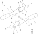
- einen Schnitt gemäß
Figur 4 , jedoch bei stehender Halterung und aus der bei rotierender Welle eingenommenen Stellung heraus gedrehten Werkzeugen, - Fig. 6
- einen vertikalen Schnitt durch die Halterung und die Werkzeuge, und
- Fig. 7
- einen vertikalen Schnitt durch die Halterung und die in vertikaler Richtung verstellten Werkzeuge.
- Eine in der
Figur 1 gezeigte landwirtschaftliche Erntemaschine 10 in der Art eines selbstfahrenden Feldhäckslers baut sich auf einem Rahmen 12 auf, der von vorderen und rückwärtigen Rädern 14 und 16 getragen wird. Die vorderen Räder 14 dienen als Hauptantriebsräder, während die rückwärtigen Räder 16 lenkbar sind. Die Bedienung der Erntemaschine 10 erfolgt von einer Fahrerkabine 18 aus, von der aus ein Erntevorsatz 20 einsehbar ist. Mittels des Erntevorsatzes 20 vom Boden aufgenommenes Gut, z. B. Mais, wird über ein Einzugsgehäuse 30 einer nicht eingezeichneten Häckseltrommel im Innern der Erntemaschine 10 zugeführt, die es in kleine Stücke häckselt und es einer (ebenfalls nicht eingezeichneten) Fördervorrichtung aufgibt. Das Gut verläßt die Erntemaschine 10 zu einem nebenher fahrenden Anhänger über einen um die Hochachse drehbaren und höhenverstellbaren Auswurfkrümmer 28. Zwischen der Häckseltrommel und der Fördervorrichtung kann eine nicht eingezeichnete Nachzerkleinerungsvorrichtung angeordnet sein. Obwohl die Erfindung hier an einem Feldhäcksler dargestellt wird, kann sie auch an Mähdreschern mit zugehörigen Erntevorsätzen in Form von Maispflückem Verwendung finden. Im Folgenden beziehen sich Richtungsangaben, wie vor, hinter, seitlich und oberhalb auf die Vorwärtsrichtung der Erntemaschine 10 und des Erntevorsatzes 20, die in derFigur 1 nach links verläuft. - Zum Aufnehmen des Ernteguts dient der Erntevorsatz 20, der in Vorwärtsrichtung an der Frontseite der Erntemaschine 10 befestigt ist. Der Erntevorsatz 20 ist in der der dargestellten Ausführungsform ein an sich bekannter Maismähvorsatz, der einen Mittelteil 38 und zwei (bezüglich der Vorwärtsrichtung der Erntemaschine 10) seitlich links und rechts neben dem Mittelteil 38 angeordneten Seitenteile 40 umfasst. Die Seitenteile 40 sind zum Straßentransport nach oben schwenkbar am Mittelteil 38 befestigt und können zum Emteeinsatz hydraulisch heruntergeschwenkt werden, so dass sie beim Erntebetrieb parallel zum Mittelteil 38 verlaufen. Anschließend können sie wieder hinauf geschwenkt werden. Die
Figur 1 zeigt die Seitenteile 40 in hochgeschwenktem Zustand. Am Mittelteil 38 sind in der vorliegenden Ausführungsform vier Emteeinheiten 32 mit unteren Schneidscheiben zum Abschneiden der Pflanzen und oberen Förderscheiben zum Abtransport der Pflanzen angebracht, während an beiden Seitenteilen 40 jeweils zwei Ernteeinheiten 32 angebracht sind. Der Erntevorsatz 20 ist in an sich bekannter Weise mit Halmteilern 36, den Emteeinheiten 32, Teilerspitzen 34, Abdeckplatten und Fördermitteln ausgestattet, um das geerntete Gut der Häckseltrommel der Erntemaschine 10 zuzuführen. Der Erntevorsatz 20 zieht im Betrieb die Stängel des Mähguts in aufrechter Stellung ein, schneidet sie ab und führt sie dem Einzugsgehäuse 30 zu, vom dem zur Häckseltrommel der Erntemaschine 10 gefördert werden. - Der Erntevorsatz 20 umfasst einen Trägerrahmen, der einen unteren Querträger 42 und einen oberen Querträger 44 aufweist. Der untere Querträger 42 erstreckt sich unten an der Rückseite des Erntevorsatzes 20 und umfasst drei Segmente, von denen jeweils eines dem Mittelteil 38 und eines jedem Seitenteil 40 zugeordnet ist. An der Vorderseite des unteren Querträgers 42 sind Getriebegehäuse 46 angeschraubt, die zum Antrieb jeweils einer Ernteeinheit 32 dienen. Eine Antriebswelle 48 zum Antrieb der Emteeinheiten 32 über in den Getriebegehäusen 46 angeordnete Getriebe, die auch zum Antrieb der weiteren Fördermittel des Erntevorsatzes 20 dient und von einer Abtriebswelle der Erntemaschine 10 angetrieben wird, erstreckt sich in seitlicher Richtung innerhalb des hohlen unteren Querträgers 42.
- Der obere Querträger 44 erstreckt sich in seitlicher Richtung oberhalb des Einlasses des Einzugsgehäuses 30 über dessen Breite. Er ist mit hakenförmigen Tragelementen verbunden, die von komplementären Tragelementen des Einzugsgehäuses 30 teilweise untergriffen werden und zur Befestigung des Erntevorsatzes 20 an der Erntemaschine 10 dienen. Er ist durch sich vertikal erstreckende Träger und Verbindungsbleche mit dem unteren Querträger 42 verbunden. Der Trägerrahmen mit den Querträgern 42, 44 und den sich vertikal erstreckenden Trägem und Verbindungsblechen bildet somit ein Skelett des Erntevorsatzes 20, das alle weiteren Elemente des Erntevorsatzes 20 trägt.
- Rückwärtig jeder Ernteeinheit 32 ist jeweils ein Mulchgerät 50 angebracht. Das Mulchgerät 50 ist mit seiner Drehachse in seitlicher Richtung rückwärtig von der Drehachse der zugehörigen Emteeinheit 32 angeordnet. Dort laufen im normalen Emtebetrieb die Pflanzen ein. Falls eine Emteeinheit 32 mehrere Pflanzenreihen aberntet, können ihr mehrere Mulchgeräte 50 zugeordnet werden, deren Drehachsen rückwärtig der zu erwartenden Einlaufstellen der Pflanzenreihen angeordnet sind. Es wäre auch denkbar, die Mulchgeräte 50 lückenlos oder mit kleinen Lücken über die ganze Arbeitsbreite des Erntevorsatzes 20 zu verteilen.
- Es wird nun auf die
Figur 2 verwiesen. Das Mulchgerät 50 umfasst zwei sich diametral gegenüber liegende Werkzeuge 54, die über Pendellagerungen 58 um die Hochachse pendelnd mit einer mittigen Halterung 56 verbunden sind. Die Halterung 56 ist ihrerseits mit einer Welle 60 (s.Figur 3 ) verbunden, deren Drehachse sich parallel zu den Achsen erstreckt, um welche die Werkzeuge durch die Pendellagerungen 58 an der Halterung 56 schwenkbar gelagert sind. - Die Welle 60 ist an ihrem unteren Ende mit der Halterung 56 verbunden und an ihrem oberen Ende mit einem Getriebe 62 antriebsverbunden, das durch die Antriebswelle 48 antreibbar ist. Die Welle 60 ist gegenüber der Antriebswelle 48 und dem unteren Querträger 42 um die Achse der Antriebswelle 48 frei schwenkbar gelagert. Eine Abdeckung 64, die das Mulchgerät nach hinten und rückwärtig der Welle 60 nach oben hin abdeckt, umschließt die Welle 60 und bewegt sich mit der Welle 60 und dem Mulchgerät 50 bodenkopierend um die Achse der Antriebswelle 48. Weitere Einzelheiten hierzu sind in der
EP 3 272 199 A1 beschrieben, deren Offenbarung durch Verweis mit in die vorliegenden Unterlagen aufgenommen wird. - Die Halterung 56 umfasst einen oberen Teil 68, der mit der Welle 60 verbunden ist, sowie einen unteren Teil 66. Zwischen den beiden Teilen 66, 68 sind die Werkzeuge 54 positioniert. Die beiden Teile 66, 68 sind untereinander durch die Pendellagerungen 58 verbunden.
- Die Werkzeuge 54 umfassen jeweils einen distalen Teil 70, der sich (wenn sich die Welle 60 dreht und die Werkzeuge 54 durch die Fliehkraft nach außen gezogen und nicht durch Fremdkörper beeinflusst werden) in radialer Richtung von den Pendellagerungen 58 nach außen erstreckt, und einen proximalen Teil 72, der sich (wenn sich die Welle 60 dreht und die Werkzeuge 54 durch die Fliehkraft nach außen gezogen und nicht durch Fremdkörper beeinflusst werden) von den Pendellagerungen 58 nach innen erstreckt und dessen Details und Nutzen nachfolgend erläutert werden. Am äußeren Ende des distalen Teils 70 sind Schlagkörper 74 angeordnet, die zum Zerschlagen von Pflanzenstoppeln dienen, die nach dem Abernten auf dem Feld stehen bleiben. Die Schlagkörper 74 sind als Zylinder mit nach innen und oben ansteigenden Außenkanten ausgeführt, könnten aber eine beliebige andere Form aufweisen und/oder durch Schneiden ersetzt oder ergänzt werden. Während der distale Teil 70 und der proximale Teil 72 des Werkzeugs 54 vorzugsweise einteilig hergestellt sind, können die Schlagkörper als separate Elemente hergestellt und lösbar (z.B. durch Schrauben) oder unlösbar mit dem distalen Teil 70 verbunden sein oder ebenfalls einteilig mit dem übrigen Werkzeug 54 hergestellt sein, z.B. als Fräs-, Guss- oder Schmiedeteil.
- Die beiden Werkzeuge sind baugleich und im montierten Zustand bezüglich einer sich quer zur Längsachse der Welle erstreckende Achse zueinander um 180° gedreht, wie in den
Figuren 3 bis 5 erkennbar ist. Man benötigt somit nicht zwei verschiedene Werkzeuge 54 für das Mulchgerät 50, was die Ersatzteilhaltung vereinfacht. - Es wird nun auf die
Figur 4 verwiesen, in welcher das Mulchgerät 50 in einer Ober- oder Unteransicht gezeigt ist, um insbesondere die Form und Aufgabe der proximalen Teile 72 darzustellen. Die proximalen Teile 72 erstrecken sich von der Pendellagerung 58 ausgehend nach innen und bis über die Drehachse der Welle 60 hinaus. Dabei ist die bezüglich der Drehrichtung im normalen Betrieb, die durch die Pfeile 78 veranschaulicht wird, vorlaufende Kante 80 des proximalen Teils 72 jeweils geradlinig, während sich die nachlaufende Kante 82 nach innen verlaufend der vorlaufenden Kante 80 geradlinig annähert. Jenseits der Drehachse der Welle ist der proximale Teils 72 als Haken 84 ausgeformt, d.h. die nachlaufende Kante 82 erstreckt sich dort zunächst wieder von der vorlaufenden Kante 80 hinweg und bildet einen Anschlag, der an der nachlaufenden Kante 82 des proximalen Teil 72 des jeweils anderen Werkzeugs 54 anliegt. Die aneinander liegenden Bereiche des Hakens 84 einerseits und der nachlaufenden Kante 80 des proximalen Teils 72 des anderen Werkzeugs 54 andererseits sind parallel zueinander ausgerichtet, um eine möglichst große Anlagefläche zu erzielen. - Man erhält auf diese Weise einen Anschlag zwischen den beiden proximalen Teilen 72 der beiden Werkzeuge 54, der den möglichen Winkel begrenzt, den die Werkzeuge 54 um die Pendelachsen 58 drehen können, und zwar in der vorlaufenden Richtung, wie sie durch die Pfeile 78 dargestellt ist. Die Werkzeuge 54 können sich somit nicht genau radial erstrecken, wie man anhand der
Figur 4 erkennt, ohne aneinander anzuschlagen. Dadurch wird die unerwünschte Pendelbewegung der Werkzeuge 54 um die Pendelachsen 58 vermieden. Entgegen der Drehrichtung können die Werkzeuge 54 jedoch, z.B. beim Aufprall gegen einen Fremdkörper, problemlos ausweichen, wie in derFigur 5 gezeigt. - Die proximalen Teile 72 bilden in ihrer Mitte eine Aussparung, durch die eine Mutter 76 zugänglich ist, die zur Befestigung der Welle 60 an der Halterung 56 dient.
- Die Werkzeuge 54 können durch formschlüssige Merkmale am Werkzeug 54 und der in der Pendellagerung 58 zur Lagerung verwendeten Buchse, zusätzlich zur Wirkung der Fliehkraft, in eine fast radiale Ausrichtung vorgespannt werden, wie in der
DE 10 2016 213 919 A1 beschrieben, deren Offenbarung durch Verweis mit in die vorliegenden Unterlagen aufgenommen wird. - Wie in den
Figuren 6 und 7 gezeigt, erlauben die Pendellagerungen 58, zusätzlich zur Drehung der Werkzeuge 54 um die parallel zur Drehachse der Welle 60 verlaufenden Achse, auch eine begrenzte Pendelbewegung der Werkzeuge um eine horizontale, tangential zur Drehrichtung des Mulchgeräts 50 orientierte Drehachse.
Claims (6)
- Mulchgerät (50) zur Bearbeitung von Pflanzenstoppeln auf einem Feld, insbesondere zur Anbringung an einem Erntevorsatz (20), umfassend eine Halterung (56), die mit einer Welle (60) verbunden und durch die Welle (60) in eine Rotationsbewegung versetzbar ist, zwei diametral gegenüberliegend an der Halterung (56) angebrachte Werkzeuge (54), die durch Pendellagerungen (58) mit parallel zur Drehachse der Welle (60) verlaufenden Pendelachsen frei pendelnd an der Halterung (56) gelagert sind, sowie Mittel zur Begrenzung des sich bei rotierender Welle (60) durch die Fliehkraft ergebenden Pendelwinkels der Werkzeuge (54) in der Drehrichtung der Welle (60) auf einen maximalen Winkel, welche Mittel konfiguriert sind, den bei rotierender Welle (60) fliehkraftbedingt eingenommenen, maximalen Winkel der Werkzeuge (54) in eine gegenüber einer genau radialen Ausrichtung der Werkzeuge (54) nachlaufende Stellung zu begrenzen, wobei die Mittel zur Begrenzung des Pendelwinkels der Werkzeuge (54) Bereiche der Werkzeuge (54) umfassen, die bei rotierender Welle (60) zusammenwirken, wobei die Werkzeuge (54) einen distalen Teil (70), der sich in der bei rotierender Welle (60) eingenommenen Stellung der Werkzeuge (54) von der Pendellagerung (58) nach außen erstreckt, und einen proximalen Teil (72) umfassen, der sich in der bei rotierender Welle (60) eingenommenen Stellung der Werkzeuge (54) von der Pendellagerung nach innen erstreckt, und wobei die zusammenwirkenden Bereiche an den proximalen Teilen (70,72) vorgesehen sind, dadurch gekennzeichnet, dass die zusammenwirkenden Bereiche einen Haken (84) umfassen, der mit dem proximalen Teil (72) des jeweils anderen Werkzeugs (54) zusammenwirkt und dass der Haken (84) jeweils an einer Fläche des anderen Werkzeugs (54) anliegt, die sich zwischen dem inneren Ende des proximalen Teils (72) und der Pendellagerung (58) befindet.
- Mulchgerät (50) nach Anspruch 1, wobei die Werkzeuge (54) am äußeren Ende des distalen Bereichs (70) mit Schneiden und/oder Schlagkörpem (74) versehen sind.
- Mulchgerät (50) nach einem der vorhergehenden Ansprüche, wobei die beiden Werkzeuge (54) baugleich und bezüglich einer sich quer zur Längsachse der Welle erstreckende Achse zueinander um 180° gedreht sind.
- Mulchgerät (50) nach einem der vorhergehenden Ansprüche, wobei die Pendellagerungen (58), zusätzlich zur Drehung der Werkzeuge (54) um die parallel zur Drehachse der Welle (60) verlaufenden Achse, auch eine begrenzte Pendelbewegung der Werkzeuge um eine horizontale, tangential zur Drehrichtung des Mulchgeräts (50) orientierte Drehachse erlauben.
- Erntevorsatz (20) mit einem Mulchgerät (50) nach einem der vorhergehenden Ansprüche.
- Selbstfahrende Erntemaschine (10) mit einem Erntevorsatz (20) nach Anspruch 5.
Applications Claiming Priority (1)
| Application Number | Priority Date | Filing Date | Title |
|---|---|---|---|
| DE102019216223.1A DE102019216223A1 (de) | 2019-10-22 | 2019-10-22 | Mulchgerät zur Bearbeitung von auf einem Feld stehenden Pflanzenstoppeln mit Pendelwinkelbegrenzung |
Publications (2)
| Publication Number | Publication Date |
|---|---|
| EP3811759A1 EP3811759A1 (de) | 2021-04-28 |
| EP3811759B1 true EP3811759B1 (de) | 2025-04-23 |
Family
ID=72644052
Family Applications (1)
| Application Number | Title | Priority Date | Filing Date |
|---|---|---|---|
| EP20197876.4A Active EP3811759B1 (de) | 2019-10-22 | 2020-09-23 | Mulchgerät zur bearbeitung von auf einem feld stehenden pflanzenstoppeln mit pendelwinkelbegrenzung |
Country Status (2)
| Country | Link |
|---|---|
| EP (1) | EP3811759B1 (de) |
| DE (1) | DE102019216223A1 (de) |
Families Citing this family (1)
| Publication number | Priority date | Publication date | Assignee | Title |
|---|---|---|---|---|
| DE102020206950A1 (de) | 2020-06-03 | 2021-12-09 | Deere & Company | Werkzeug für ein Mulchgerät zur Bearbeitung von Pflanzenstoppeln auf einem Feld |
Citations (1)
| Publication number | Priority date | Publication date | Assignee | Title |
|---|---|---|---|---|
| EP0365019B1 (de) * | 1988-10-19 | 1993-03-24 | BISO GmbH Maschinenfabrik | Pflückvorrichtung zum Ernten von Halmfrüchten, insbesondere Mais |
Family Cites Families (6)
| Publication number | Priority date | Publication date | Assignee | Title |
|---|---|---|---|---|
| US3762137A (en) * | 1972-10-02 | 1973-10-02 | D Veretto | Stalk shredder |
| US4062171A (en) * | 1976-08-30 | 1977-12-13 | Massey-Ferguson Inc. | Cutter blade assembly |
| DE102005023012B4 (de) | 2005-05-19 | 2008-06-05 | ESM Ennepetaler Schneid- und Mähtechnik GmbH & Co KG | Verfahren und Vorrichtung zum Abschneiden und Zerschneiden von insbesondere hoch wachsendem Schnittgut |
| US9010078B2 (en) * | 2012-08-09 | 2015-04-21 | Randy MacDonald | Weed trimmer with a wingnut plate |
| DE102017207337A1 (de) | 2016-07-20 | 2018-01-25 | Deere & Company | Mulchgerät zur Bearbeitung von auf einem Feld stehenden Pflanzenstümpfen |
| DE102016213919A1 (de) | 2016-07-28 | 2018-02-01 | Deere & Company | Aufhängung eines Messers eines Stängelhäckslers für ein Maiserntegerät |
-
2019
- 2019-10-22 DE DE102019216223.1A patent/DE102019216223A1/de active Pending
-
2020
- 2020-09-23 EP EP20197876.4A patent/EP3811759B1/de active Active
Patent Citations (1)
| Publication number | Priority date | Publication date | Assignee | Title |
|---|---|---|---|---|
| EP0365019B1 (de) * | 1988-10-19 | 1993-03-24 | BISO GmbH Maschinenfabrik | Pflückvorrichtung zum Ernten von Halmfrüchten, insbesondere Mais |
Also Published As
| Publication number | Publication date |
|---|---|
| EP3811759A1 (de) | 2021-04-28 |
| DE102019216223A1 (de) | 2021-04-22 |
Similar Documents
| Publication | Publication Date | Title |
|---|---|---|
| EP3272199B1 (de) | Mulchgerät zur bearbeitung von auf einem feld stehenden pflanzenstümpfen | |
| EP3269223B1 (de) | Erntevorsatz mit einer mulcheinrichtung | |
| EP3622798B1 (de) | Anordnung zur steuerung der höhe und/oder neigung eines erntevorsatzes zur ernte stängelartigen ernteguts | |
| EP3420804B1 (de) | Häckselmesser für einen strohhäcksler | |
| EP3391724B1 (de) | Mulchgerät zur bearbeitung von auf einem feld stehenden pflanzenstümpfen mit verstellbarer position und/oder bodenandruckkraft | |
| EP1671532B1 (de) | Häckseltrommel | |
| DE102017222587B4 (de) | Mulchgerät zur Bearbeitung von auf einem Feld stehenden Pflanzenstümpfen mit verstellbarer Position und/oder Bodenandruckkraft | |
| EP2965611A1 (de) | Stängelhäcksler für ein maiserntegerät | |
| EP1479282A1 (de) | Häckselmesser für einen Strohhäcksler | |
| EP3354126B1 (de) | Häckselmund und häckseltrommel für einen feldhäcksler | |
| EP3469865B1 (de) | Mulchgerät mit schlegel- und sichelmähwerk | |
| EP0030568B1 (de) | Schneidwerk zum Beschneiden von Hecken und Büschen oder dergleichen | |
| EP2792232B1 (de) | Aufnahmeeinrichtung für Häcksler für Schnittgut | |
| EP3881665B1 (de) | Mulchgerät zur bearbeitung von pflanzenstoppeln | |
| EP1566092A1 (de) | Erntegerät mit einem Stängelhäcksler | |
| EP3811759A1 (de) | Mulchgerät zur bearbeitung von auf einem feld stehenden pflanzenstoppeln mit pendelwinkelbegrenzung | |
| DE102016213919A1 (de) | Aufhängung eines Messers eines Stängelhäckslers für ein Maiserntegerät | |
| DE102005055621B3 (de) | Maschine zur Ernte stängelartiger Pflanzen | |
| DE3011450A1 (de) | Fahrbare maeh- und konditioniermaschine fuer die gewinnung von ernteschnittgut | |
| DE102016214324A1 (de) | Erntevorsatz mit einem Mulchgerät zur Bearbeitung von auf einem Feld stehenden Pflanzenstümpfen | |
| DE102009028410B4 (de) | Strohhäcksler eines Mähdreschers | |
| DE102016208511B4 (de) | Maschine zur Ernte stängelartiger Pflanzen mit einer Schneidenanordnung zum Zerkleinern der Stoppeln | |
| DE102015217852B4 (de) | Erntevorsatz mit Mulchgeräten | |
| EP3545741B1 (de) | Mulchmesser für ein mähgerät | |
| EP3918903B1 (de) | Werkzeug für ein mulchgerät zur bearbeitung von pflanzenstoppeln auf einem feld |
Legal Events
| Date | Code | Title | Description |
|---|---|---|---|
| PUAI | Public reference made under article 153(3) epc to a published international application that has entered the european phase |
Free format text: ORIGINAL CODE: 0009012 |
|
| STAA | Information on the status of an ep patent application or granted ep patent |
Free format text: STATUS: THE APPLICATION HAS BEEN PUBLISHED |
|
| AK | Designated contracting states |
Kind code of ref document: A1 Designated state(s): AL AT BE BG CH CY CZ DE DK EE ES FI FR GB GR HR HU IE IS IT LI LT LU LV MC MK MT NL NO PL PT RO RS SE SI SK SM TR |
|
| AX | Request for extension of the european patent |
Extension state: BA ME |
|
| STAA | Information on the status of an ep patent application or granted ep patent |
Free format text: STATUS: REQUEST FOR EXAMINATION WAS MADE |
|
| 17P | Request for examination filed |
Effective date: 20211028 |
|
| RBV | Designated contracting states (corrected) |
Designated state(s): AL AT BE BG CH CY CZ DE DK EE ES FI FR GB GR HR HU IE IS IT LI LT LU LV MC MK MT NL NO PL PT RO RS SE SI SK SM TR |
|
| STAA | Information on the status of an ep patent application or granted ep patent |
Free format text: STATUS: EXAMINATION IS IN PROGRESS |
|
| 17Q | First examination report despatched |
Effective date: 20221005 |
|
| GRAP | Despatch of communication of intention to grant a patent |
Free format text: ORIGINAL CODE: EPIDOSNIGR1 |
|
| STAA | Information on the status of an ep patent application or granted ep patent |
Free format text: STATUS: GRANT OF PATENT IS INTENDED |
|
| INTG | Intention to grant announced |
Effective date: 20241223 |
|
| GRAS | Grant fee paid |
Free format text: ORIGINAL CODE: EPIDOSNIGR3 |
|
| GRAA | (expected) grant |
Free format text: ORIGINAL CODE: 0009210 |
|
| STAA | Information on the status of an ep patent application or granted ep patent |
Free format text: STATUS: THE PATENT HAS BEEN GRANTED |
|
| AK | Designated contracting states |
Kind code of ref document: B1 Designated state(s): AL AT BE BG CH CY CZ DE DK EE ES FI FR GB GR HR HU IE IS IT LI LT LU LV MC MK MT NL NO PL PT RO RS SE SI SK SM TR |
|
| REG | Reference to a national code |
Ref country code: GB Ref legal event code: FG4D Free format text: NOT ENGLISH |
|
| REG | Reference to a national code |
Ref country code: CH Ref legal event code: EP |
|
| REG | Reference to a national code |
Ref country code: DE Ref legal event code: R096 Ref document number: 502020010878 Country of ref document: DE |
|
| REG | Reference to a national code |
Ref country code: IE Ref legal event code: FG4D Free format text: LANGUAGE OF EP DOCUMENT: GERMAN |
|
| REG | Reference to a national code |
Ref country code: NL Ref legal event code: MP Effective date: 20250423 |
|
| PG25 | Lapsed in a contracting state [announced via postgrant information from national office to epo] |
Ref country code: NL Free format text: LAPSE BECAUSE OF FAILURE TO SUBMIT A TRANSLATION OF THE DESCRIPTION OR TO PAY THE FEE WITHIN THE PRESCRIBED TIME-LIMIT Effective date: 20250423 |
|
| PG25 | Lapsed in a contracting state [announced via postgrant information from national office to epo] |
Ref country code: PT Free format text: LAPSE BECAUSE OF FAILURE TO SUBMIT A TRANSLATION OF THE DESCRIPTION OR TO PAY THE FEE WITHIN THE PRESCRIBED TIME-LIMIT Effective date: 20250825 Ref country code: ES Free format text: LAPSE BECAUSE OF FAILURE TO SUBMIT A TRANSLATION OF THE DESCRIPTION OR TO PAY THE FEE WITHIN THE PRESCRIBED TIME-LIMIT Effective date: 20250423 Ref country code: FI Free format text: LAPSE BECAUSE OF FAILURE TO SUBMIT A TRANSLATION OF THE DESCRIPTION OR TO PAY THE FEE WITHIN THE PRESCRIBED TIME-LIMIT Effective date: 20250423 |
|
| PGFP | Annual fee paid to national office [announced via postgrant information from national office to epo] |
Ref country code: DE Payment date: 20250820 Year of fee payment: 6 |
|
| REG | Reference to a national code |
Ref country code: LT Ref legal event code: MG9D |
|
| PG25 | Lapsed in a contracting state [announced via postgrant information from national office to epo] |
Ref country code: NO Free format text: LAPSE BECAUSE OF FAILURE TO SUBMIT A TRANSLATION OF THE DESCRIPTION OR TO PAY THE FEE WITHIN THE PRESCRIBED TIME-LIMIT Effective date: 20250723 Ref country code: GR Free format text: LAPSE BECAUSE OF FAILURE TO SUBMIT A TRANSLATION OF THE DESCRIPTION OR TO PAY THE FEE WITHIN THE PRESCRIBED TIME-LIMIT Effective date: 20250724 |
|
| PG25 | Lapsed in a contracting state [announced via postgrant information from national office to epo] |
Ref country code: PL Free format text: LAPSE BECAUSE OF FAILURE TO SUBMIT A TRANSLATION OF THE DESCRIPTION OR TO PAY THE FEE WITHIN THE PRESCRIBED TIME-LIMIT Effective date: 20250423 |
|
| PG25 | Lapsed in a contracting state [announced via postgrant information from national office to epo] |
Ref country code: BG Free format text: LAPSE BECAUSE OF FAILURE TO SUBMIT A TRANSLATION OF THE DESCRIPTION OR TO PAY THE FEE WITHIN THE PRESCRIBED TIME-LIMIT Effective date: 20250423 |
|
| PG25 | Lapsed in a contracting state [announced via postgrant information from national office to epo] |
Ref country code: HR Free format text: LAPSE BECAUSE OF FAILURE TO SUBMIT A TRANSLATION OF THE DESCRIPTION OR TO PAY THE FEE WITHIN THE PRESCRIBED TIME-LIMIT Effective date: 20250423 |
|
| PG25 | Lapsed in a contracting state [announced via postgrant information from national office to epo] |
Ref country code: RS Free format text: LAPSE BECAUSE OF FAILURE TO SUBMIT A TRANSLATION OF THE DESCRIPTION OR TO PAY THE FEE WITHIN THE PRESCRIBED TIME-LIMIT Effective date: 20250723 |
|
| PG25 | Lapsed in a contracting state [announced via postgrant information from national office to epo] |
Ref country code: IS Free format text: LAPSE BECAUSE OF FAILURE TO SUBMIT A TRANSLATION OF THE DESCRIPTION OR TO PAY THE FEE WITHIN THE PRESCRIBED TIME-LIMIT Effective date: 20250823 |
|
| PG25 | Lapsed in a contracting state [announced via postgrant information from national office to epo] |
Ref country code: LV Free format text: LAPSE BECAUSE OF FAILURE TO SUBMIT A TRANSLATION OF THE DESCRIPTION OR TO PAY THE FEE WITHIN THE PRESCRIBED TIME-LIMIT Effective date: 20250423 |
|
| REG | Reference to a national code |
Ref country code: CH Ref legal event code: W10 Free format text: ST27 STATUS EVENT CODE: U-0-0-W10-W00 (AS PROVIDED BY THE NATIONAL OFFICE) Effective date: 20251119 |
|
| RAP4 | Party data changed (patent owner data changed or rights of a patent transferred) |
Owner name: DEERE & COMPANY |
|
| PG25 | Lapsed in a contracting state [announced via postgrant information from national office to epo] |
Ref country code: DK Free format text: LAPSE BECAUSE OF FAILURE TO SUBMIT A TRANSLATION OF THE DESCRIPTION OR TO PAY THE FEE WITHIN THE PRESCRIBED TIME-LIMIT Effective date: 20250423 Ref country code: SM Free format text: LAPSE BECAUSE OF FAILURE TO SUBMIT A TRANSLATION OF THE DESCRIPTION OR TO PAY THE FEE WITHIN THE PRESCRIBED TIME-LIMIT Effective date: 20250423 |
|
| PG25 | Lapsed in a contracting state [announced via postgrant information from national office to epo] |
Ref country code: CZ Free format text: LAPSE BECAUSE OF FAILURE TO SUBMIT A TRANSLATION OF THE DESCRIPTION OR TO PAY THE FEE WITHIN THE PRESCRIBED TIME-LIMIT Effective date: 20250423 |
|
| PG25 | Lapsed in a contracting state [announced via postgrant information from national office to epo] |
Ref country code: EE Free format text: LAPSE BECAUSE OF FAILURE TO SUBMIT A TRANSLATION OF THE DESCRIPTION OR TO PAY THE FEE WITHIN THE PRESCRIBED TIME-LIMIT Effective date: 20250423 |
|
| REG | Reference to a national code |
Ref country code: DE Ref legal event code: R097 Ref document number: 502020010878 Country of ref document: DE |
|
| PG25 | Lapsed in a contracting state [announced via postgrant information from national office to epo] |
Ref country code: SK Free format text: LAPSE BECAUSE OF FAILURE TO SUBMIT A TRANSLATION OF THE DESCRIPTION OR TO PAY THE FEE WITHIN THE PRESCRIBED TIME-LIMIT Effective date: 20250423 Ref country code: RO Free format text: LAPSE BECAUSE OF FAILURE TO SUBMIT A TRANSLATION OF THE DESCRIPTION OR TO PAY THE FEE WITHIN THE PRESCRIBED TIME-LIMIT Effective date: 20250423 |
|
| PG25 | Lapsed in a contracting state [announced via postgrant information from national office to epo] |
Ref country code: IT Free format text: LAPSE BECAUSE OF FAILURE TO SUBMIT A TRANSLATION OF THE DESCRIPTION OR TO PAY THE FEE WITHIN THE PRESCRIBED TIME-LIMIT Effective date: 20250423 |
|
| PLBE | No opposition filed within time limit |
Free format text: ORIGINAL CODE: 0009261 |
|
| STAA | Information on the status of an ep patent application or granted ep patent |
Free format text: STATUS: NO OPPOSITION FILED WITHIN TIME LIMIT |
|
| REG | Reference to a national code |
Ref country code: CH Ref legal event code: L10 Free format text: ST27 STATUS EVENT CODE: U-0-0-L10-L00 (AS PROVIDED BY THE NATIONAL OFFICE) Effective date: 20260304 |
|
| 26N | No opposition filed |
Effective date: 20260126 |
|
| REG | Reference to a national code |
Ref country code: CH Ref legal event code: H13 Free format text: ST27 STATUS EVENT CODE: U-0-0-H10-H13 (AS PROVIDED BY THE NATIONAL OFFICE) Effective date: 20260425 |