EP3811704B1 - Accès au canal par modèle d'accès au canal organisé de manière hiérarchique - Google Patents
Accès au canal par modèle d'accès au canal organisé de manière hiérarchique Download PDFInfo
- Publication number
- EP3811704B1 EP3811704B1 EP19732972.5A EP19732972A EP3811704B1 EP 3811704 B1 EP3811704 B1 EP 3811704B1 EP 19732972 A EP19732972 A EP 19732972A EP 3811704 B1 EP3811704 B1 EP 3811704B1
- Authority
- EP
- European Patent Office
- Prior art keywords
- channel access
- access pattern
- resources
- network
- frequency
- Prior art date
- Legal status (The legal status is an assumption and is not a legal conclusion. Google has not performed a legal analysis and makes no representation as to the accuracy of the status listed.)
- Active
Links
- 238000004891 communication Methods 0.000 claims description 277
- 238000000034 method Methods 0.000 claims description 83
- 238000012546 transfer Methods 0.000 claims description 21
- 238000004590 computer program Methods 0.000 claims description 14
- 230000005540 biological transmission Effects 0.000 description 117
- 238000010586 diagram Methods 0.000 description 51
- 230000000694 effects Effects 0.000 description 49
- 230000000737 periodic effect Effects 0.000 description 27
- 230000006870 function Effects 0.000 description 17
- 230000011664 signaling Effects 0.000 description 13
- 238000013461 design Methods 0.000 description 11
- 230000000875 corresponding effect Effects 0.000 description 9
- 230000008901 benefit Effects 0.000 description 8
- 238000004088 simulation Methods 0.000 description 8
- 230000002123 temporal effect Effects 0.000 description 8
- 238000001514 detection method Methods 0.000 description 7
- 238000009826 distribution Methods 0.000 description 7
- 230000008859 change Effects 0.000 description 4
- 238000013507 mapping Methods 0.000 description 4
- 241001136792 Alle Species 0.000 description 3
- 238000000342 Monte Carlo simulation Methods 0.000 description 3
- 125000004122 cyclic group Chemical group 0.000 description 3
- 238000000926 separation method Methods 0.000 description 3
- 230000009897 systematic effect Effects 0.000 description 3
- VIEYMVWPECAOCY-UHFFFAOYSA-N 7-amino-4-(chloromethyl)chromen-2-one Chemical compound ClCC1=CC(=O)OC2=CC(N)=CC=C21 VIEYMVWPECAOCY-UHFFFAOYSA-N 0.000 description 2
- 230000009286 beneficial effect Effects 0.000 description 2
- 238000004364 calculation method Methods 0.000 description 2
- 238000012937 correction Methods 0.000 description 2
- 230000007423 decrease Effects 0.000 description 2
- 230000001419 dependent effect Effects 0.000 description 2
- 238000005265 energy consumption Methods 0.000 description 2
- 230000009467 reduction Effects 0.000 description 2
- 230000001105 regulatory effect Effects 0.000 description 2
- 230000001360 synchronised effect Effects 0.000 description 2
- 238000009827 uniform distribution Methods 0.000 description 2
- 241000271946 Bitis gabonica Species 0.000 description 1
- 235000008694 Humulus lupulus Nutrition 0.000 description 1
- 230000003044 adaptive effect Effects 0.000 description 1
- 230000002411 adverse Effects 0.000 description 1
- 230000001174 ascending effect Effects 0.000 description 1
- 230000006399 behavior Effects 0.000 description 1
- 230000002457 bidirectional effect Effects 0.000 description 1
- 230000015572 biosynthetic process Effects 0.000 description 1
- 230000002596 correlated effect Effects 0.000 description 1
- 238000011161 development Methods 0.000 description 1
- 230000018109 developmental process Effects 0.000 description 1
- 238000006073 displacement reaction Methods 0.000 description 1
- 238000007429 general method Methods 0.000 description 1
- 230000001788 irregular Effects 0.000 description 1
- 230000007774 longterm Effects 0.000 description 1
- 238000007726 management method Methods 0.000 description 1
- 238000012986 modification Methods 0.000 description 1
- 230000004048 modification Effects 0.000 description 1
- 230000003287 optical effect Effects 0.000 description 1
- 238000005457 optimization Methods 0.000 description 1
- 238000013439 planning Methods 0.000 description 1
- 230000008569 process Effects 0.000 description 1
- 238000012545 processing Methods 0.000 description 1
- 238000011084 recovery Methods 0.000 description 1
- 238000013468 resource allocation Methods 0.000 description 1
- 230000008054 signal transmission Effects 0.000 description 1
- 210000002023 somite Anatomy 0.000 description 1
- 238000012384 transportation and delivery Methods 0.000 description 1
Images


Classifications
-
- H—ELECTRICITY
- H04—ELECTRIC COMMUNICATION TECHNIQUE
- H04W—WIRELESS COMMUNICATION NETWORKS
- H04W48/00—Access restriction; Network selection; Access point selection
- H04W48/08—Access restriction or access information delivery, e.g. discovery data delivery
- H04W48/12—Access restriction or access information delivery, e.g. discovery data delivery using downlink control channel
-
- H—ELECTRICITY
- H04—ELECTRIC COMMUNICATION TECHNIQUE
- H04W—WIRELESS COMMUNICATION NETWORKS
- H04W72/00—Local resource management
- H04W72/04—Wireless resource allocation
- H04W72/044—Wireless resource allocation based on the type of the allocated resource
- H04W72/0446—Resources in time domain, e.g. slots or frames
-
- H—ELECTRICITY
- H04—ELECTRIC COMMUNICATION TECHNIQUE
- H04B—TRANSMISSION
- H04B1/00—Details of transmission systems, not covered by a single one of groups H04B3/00 - H04B13/00; Details of transmission systems not characterised by the medium used for transmission
- H04B1/69—Spread spectrum techniques
- H04B1/713—Spread spectrum techniques using frequency hopping
- H04B1/7143—Arrangements for generation of hop patterns
-
- H—ELECTRICITY
- H04—ELECTRIC COMMUNICATION TECHNIQUE
- H04W—WIRELESS COMMUNICATION NETWORKS
- H04W72/00—Local resource management
- H04W72/04—Wireless resource allocation
- H04W72/044—Wireless resource allocation based on the type of the allocated resource
- H04W72/0453—Resources in frequency domain, e.g. a carrier in FDMA
-
- H—ELECTRICITY
- H04—ELECTRIC COMMUNICATION TECHNIQUE
- H04W—WIRELESS COMMUNICATION NETWORKS
- H04W72/00—Local resource management
- H04W72/50—Allocation or scheduling criteria for wireless resources
- H04W72/51—Allocation or scheduling criteria for wireless resources based on terminal or device properties
-
- H—ELECTRICITY
- H04—ELECTRIC COMMUNICATION TECHNIQUE
- H04W—WIRELESS COMMUNICATION NETWORKS
- H04W72/00—Local resource management
- H04W72/50—Allocation or scheduling criteria for wireless resources
- H04W72/54—Allocation or scheduling criteria for wireless resources based on quality criteria
- H04W72/541—Allocation or scheduling criteria for wireless resources based on quality criteria using the level of interference
-
- H—ELECTRICITY
- H04—ELECTRIC COMMUNICATION TECHNIQUE
- H04B—TRANSMISSION
- H04B1/00—Details of transmission systems, not covered by a single one of groups H04B3/00 - H04B13/00; Details of transmission systems not characterised by the medium used for transmission
- H04B1/69—Spread spectrum techniques
- H04B1/713—Spread spectrum techniques using frequency hopping
- H04B1/715—Interference-related aspects
Definitions
- Embodiments of the present invention relate to a controller for a subscriber of a communication system, to a base station of a communication system, to an endpoint of the communication system and to the communication system, the communication system communicating wirelessly in a frequency band which is used by a plurality of communication systems for communication .
- Some embodiments relate to channel access via hierarchically organized channel access patterns.
- Interference from participants within their own radio network is often avoided by a coordinated (e.g. by a base station), conflict-free allocation of radio resources. This occurs e.g. in the mobile radio standards GSM, UMTS and LTE, where (outside the initial network registration phase) collisions between radio users within the same network can be completely avoided by so-called "scheduling".
- Each network is assigned a specific usable frequency range (possibly consisting of several frequency channels) from the entire available frequency band.
- Locally neighboring networks use different frequency ranges, which means that direct interference between participants in locally neighboring networks does not occur.
- this method also represents a form of coordination between networks.
- a network can determine an unused or e.g. the least used frequency range from a set of predetermined frequency ranges by measuring the load and then occupy or switch there.
- TSMA Telegram Splitting Multiple Access
- the frequency range that can be used by a network is subdivided into a predetermined number of frequency channels, with a data packet being transmitted divided into a plurality of partial data packets, which are typically sent at different times and on different frequency channels.
- the hopping pattern used for the transmission of the partial data packets plays a special role here, as shown in [2], for example.
- a particularly high utilization of networks can be achieved if there are as many different hopping patterns as possible, which contain only the fewest possible and also short overlapping sequences.
- the networks may use different hopping patterns relative to each other.
- each network In mutually coordinated networks it is possible to assign each network an individual hopping pattern which has as little overlap as possible with the hopping patterns of other networks within the reception range.
- the entirety of all available hopping patterns can be tabulated as a set (of hopping patterns) from which the cross-network coordinating entity assigns one or more individual hopping patterns to each network.
- a set of suitable hopping patterns can be calculated in advance according to suitable optimization criteria.
- the U.S. 2015/163814 A1 refers to a wireless fire detection system in which an area to be monitored, which is equipped with appropriate sensors, is served by several so-called gateways.
- the gateways each serve those sensors that are arranged in a reception area of the respective gateway.
- the gateways used a common hopping pattern, which is, however, applied with different offsets, so that the hopping patterns used by the gateways are versions of each other that are shifted in time.
- the U.S. 2009/074033 A1 refers to the generation of a hopping pattern that should have as little interference as possible with neighboring systems.
- the base station can listen to the frequency channels in a transmission-free time and adjust the hopping pattern used by the communication system such that frequency channels in which interference was detected are excluded from a new hopping pattern generated in this way.
- the new hopping pattern obtained in this way is communicated to the node using a so-called management message.
- the present invention is therefore based on the object of creating a concept that increases the transmission reliability between users of a communication system when the users of the communication system access a frequency band which is used for wireless communication by a number of communication systems that are not coordinated with one another.
- channel access patterns are mentioned that indicate usable frequency and/or time hopping based allocations of resources. However, only channel access patterns specifying usable frequency and time hopping based allocations of resources fall within the scope of the claims.
- Embodiments provide an endpoint of a communication system, wherein the communication system operates in a frequency band [eg, a license-free and/or license-free frequency band; e.g. ISM band] communicates wirelessly, which is used by a plurality of communication systems for communication, the endpoint being designed to receive a signal [e.g. a beacon signal], the signal having information about a network-specific channel access pattern, the network-specific channel access pattern indicates a frequency-based and/or time jump-based occupancy of resources in the frequency band that can be used for communication in the communication system [e.g. a time sequence of frequency resources that can be used for communication in the communication system (e.g.
- the endpoint being designed to To transmit data using a relative channel access pattern [e.g. to send or receive], the relative channel access pattern being an occupancy of resources to be used for the transmission from the usable frequency and/or time jump-based occupancy of resources of the network rk-specific channel access pattern indicates [eg the relative channel access pattern indicates which of the network-specific channel access pattern for the communication of the communication system released or usable resources are actually to be used for the transmission of data by the endpoint].
- a relative channel access pattern e.g. to send or receive
- the relative channel access pattern being an occupancy of resources to be used for the transmission from the usable frequency and/or time jump-based occupancy of resources of the network rk-specific channel access pattern indicates [eg the relative channel access pattern indicates which of the network-specific channel access pattern for the communication of the communication system released or usable resources are actually to be used for the transmission of data by the endpoint].
- the allocation of resources of the relative channel access pattern to be used for the transmission is a subset of the usable frequency and time jump-based allocation of resources of the network-specific channel access pattern [eg wherein the relative channel access pattern has only a subset of the resources of the network-specific channel access pattern].
- the relative channel access pattern may differ from another relative channel access pattern based on which another subscriber [e.g. endpoint and/or base station; e.g. base station to another subscriber] of the communication system transmits data [e.g. sends and/or receives], wherein the other relative channel access pattern specifies an allocation of resources to be used for the transmission by the other subscriber from the usable frequency and/or time jump-based allocation of resources of the network-specific channel access pattern.
- another subscriber e.g. endpoint and/or base station; e.g. base station to another subscriber
- the other relative channel access pattern specifies an allocation of resources to be used for the transmission by the other subscriber from the usable frequency and/or time jump-based allocation of resources of the network-specific channel access pattern.
- the network-specific channel access pattern can use the frequency- and/or time-jump-based occupancy of resources of the frequency band in frequency channels [e.g. into which the frequency band is divided] and assigned time slots or in frequency channel indices and assigned time slot indices.
- the network specific channel access pattern in frequency direction [e.g. per timeslot or timeslot index] a plurality of adjacent or spaced apart resources [e.g. frequency channels or frequency channel indices] of the frequency band.
- the relative channel access pattern in frequency direction may be at most a subset [e.g. at most one resource, i.e. one or no resource] of the plurality of contiguous or spaced apart resources of the network-specific channel access pattern.
- the relative channel access pattern for at least one time jump [e.g. for at least one time slot or time slot index] in the frequency direction can specify a different resource from the plurality of adjacent or spaced-apart resources of the network-specific channel access pattern than a different relative channel access pattern based on which another participant [e.g endpoint and/or base station; eg base station to another participant] of the communication system transmits data [eg transmits and/or receives], the other relative channel access pattern being one for transmission by the other participant indicates using allocation of resources from the usable frequency and / or time jump-based allocation of resources of the network-specific channel access pattern.
- At least two resources e.g. Frequency channels or frequency channel indices] of the plurality of resources that are adjacent or spaced apart from one another in the frequency direction can be assigned different symbol rates and/or different numbers of symbols.
- the plurality of adjacent resources in frequency direction may be a block [e.g. cluster] of contiguous resources, where different parts of the block of contiguous resources are assigned different symbol rates and/or different numbers of symbols.
- the endpoint may be configured to retrieve the relative channel access pattern from a set [e.g. supply] of M relative channel access patterns, the M relative channel access patterns specifying an allocation of resources to be used for the transmission from the usable frequency and/or time jump-based allocation of resources of the network-specific channel access pattern, the M relative channel access patterns being different [e.g. differ from a resource in at least the allocation].
- the endpoint may be configured to randomly select the relative channel access pattern from the set of M relative channel access patterns.
- the endpoint may be configured to select the relative channel access pattern from the set of M relative channel access patterns based on an intrinsic parameter.
- the immanent parameter can be a digital signature of the telegram [e.g. B. CMAC (One-key MAC)] or a code word for the detection of transmission errors [e.g. a CRC].
- a digital signature of the telegram e.g. B. CMAC (One-key MAC)
- a code word for the detection of transmission errors e.g. a CRC.
- the endpoint can be configured to select the relative channel access pattern from a Select set of relative channel access patterns with different transmission properties [e.g. different latency, or different robustness against interference].
- the endpoint may be configured to transmit as data a data packet divided into a plurality of sub-data packets according to the relative channel access pattern [e.g. to send or to receive], the plurality of sub-data packets each having only part of the data packet.
- the information may include a state of a number sequence generator [e.g. a periodic number sequence generator or a deterministic random number generator] for generating a number sequence, the number sequence determining the channel access pattern.
- a number sequence generator e.g. a periodic number sequence generator or a deterministic random number generator
- the information may be a number [e.g. a timeslot index and/or a beacon index] a sequence of numbers [e.g. a periodic time slot index sequence and/or periodic beacon index sequence], the sequence of numbers determining the channel access pattern.
- a number e.g. a timeslot index and/or a beacon index
- a sequence of numbers e.g. a periodic time slot index sequence and/or periodic beacon index sequence
- a base station of a communication system the communication system operating in a frequency band [eg a license-free and/or license-free frequency band; e.g. ISM band] communicates wirelessly, which is used by a plurality of communication systems for communication, the base station being designed to send a signal [e.g. a beacon signal], the signal having information about a network-specific channel access pattern, the network-specific channel access pattern indicates a frequency-based and/or time jump-based occupancy of resources in the frequency band that can be used for communication in the communication system [e.g. a time sequence of frequency resources that can be used for communication in the communication system (e.g. distributed over the frequency band)], the base station being designed to to transmit [e.g.
- a frequency band e.g. a license-free and/or license-free frequency band; e.g. ISM band
- the base station being designed to send a signal [e.g. a beacon signal]
- the signal having information about a network-specific channel access pattern
- the relative channel access pattern includes an allocation of resources to be used for the transmission from the usable frequency- and/or time-jump-based allocation of resources of the n network-specific channel access pattern indicates [eg indicates the relative channel access pattern, which of the network-specific channel access pattern for the Communication of the communication system released or usable resources are actually to be used for the transmission of data by the base station].
- the allocation of resources of the relative channel access pattern to be used for the transmission is a subset of the usable frequency and time hopping based allocation of resources of the network-specific channel access pattern [e.g. wherein the relative channel access pattern has only a subset of the resources of the network-specific channel access pattern].
- the base station does not know in advance which relative hopping pattern will be used by an endpoint.
- the base station can be configured to detect the relative hopping pattern used by means of a detection [e.g. B. by correlation and threshold value decision].
- the relative channel access pattern may differ from another relative channel access pattern based on which the base station transmits other data [e.g. sends and/or receives, e.g. sends to another participant and receives from another participant], where the other relative channel access pattern has an allocation of resources to be used for the transmission from the usable frequency- and/or time-jump-based allocation of resources of the network-specific channel access pattern indicates.
- the network-specific channel access pattern can use the frequency- and/or time-jump-based occupancy of resources of the frequency band in frequency channels [e.g. into which the frequency band is divided] and assigned time slots or in frequency channel indices and assigned time slot indices.
- the network specific channel access pattern in frequency direction [e.g. per timeslot or timeslot index] a plurality of adjacent or spaced apart resources [e.g. frequency channels or frequency channel indices] of the frequency band.
- the relative channel access pattern in frequency direction can be at most a subset [eg at most one resource, ie one or no resource] indicate the plurality of adjacent or spaced apart resources of the network specific channel access pattern.
- the relative channel access pattern may vary for at least one time hop [e.g. for at least one timeslot or timeslot index] specify in frequency direction a different resource of the plurality of adjacent or spaced resources of the network-specific channel access pattern than a different relative channel access pattern based on which the base station transmits different data [e.g. sends and/or receives, e.g. sends to another participant and receives from another participant], the other relative channel access pattern specifying an allocation of resources to be used for the transmission from the usable frequency and/or time jump-based allocation of resources of the network-specific channel access pattern .
- At least two resources e.g. Frequency channels or frequency channel indices] of the plurality of resources that are adjacent or spaced apart from one another in the frequency direction can be assigned different symbol rates and/or a different number of symbols.
- the plurality of adjacent resources in the frequency direction may be a block [e.g. cluster] of contiguous resources, where different parts of the block of contiguous resources are assigned different symbol rates and/or different numbers of symbols.
- the base station may be configured to select the relative channel access pattern from a set [e.g. supply] of M relative channel access patterns, the M relative channel access patterns specifying an allocation of resources to be used for the transmission from the usable frequency and/or time jump-based allocation of resources of the network-specific channel access pattern, the M relative channel access patterns being different [e.g. differ from a resource in at least the allocation].
- the base station may be configured to randomly select the relative channel access pattern from the set of M relative channel access patterns.
- the base station may be configured to select the relative channel access pattern from the set of M relative channel access patterns based on an intrinsic parameter.
- the immanent parameter can be a digital signature of the telegram [e.g. B. CMAC (One-key MAC)] or a code word for the detection of transmission errors [e.g. a CRC].
- a digital signature of the telegram e.g. B. CMAC (One-key MAC)
- a code word for the detection of transmission errors e.g. a CRC.
- the base station may be configured to adjust the relative channel access pattern depending on transmission property requirements [e.g. latency, or robustness against interference] from a set of relative channel access patterns with different transmission characteristics [e.g. different latency, or different robustness against interference].
- transmission property requirements e.g. latency, or robustness against interference
- the base station may be configured to adjust the relative channel access pattern depending on transmission property requirements [e.g. latency, or robustness to interference].
- the base station may be configured to transmit as data a data packet divided into a plurality of sub-data packets according to the relative channel access pattern [e.g. to send or to receive], the plurality of sub-data packets each having only part of the data packet.
- the information may include a state of a number sequence generator [e.g. a periodic number sequence generator or a deterministic random number generator] for generating a number sequence, the number sequence determining the channel access pattern.
- a number sequence generator e.g. a periodic number sequence generator or a deterministic random number generator
- the information may be a number [e.g. a timeslot index and/or a beacon index] a sequence of numbers [e.g. a periodic time slot index sequence and/or periodic beacon index sequence], the sequence of numbers determining the channel access pattern.
- a number e.g. a timeslot index and/or a beacon index
- a sequence of numbers e.g. a periodic time slot index sequence and/or periodic beacon index sequence
- the method further comprises a step of transmitting data using a relative channel access pattern, wherein the relative channel access pattern indicates an allocation of resources to be used for the transmission from the usable frequency- and/or time-jump-based allocation of resources of the network-specific channel access pattern [e.g. indicates the relative channel access pattern, which of the resources released or usable by the network-specific channel access pattern for the communication of the communication system are actually to be used for the transmission of data by the endpoint].
- the relative channel access pattern indicates an allocation of resources to be used for the transmission from the usable frequency- and/or time-jump-based allocation of resources of the network-specific channel access pattern [e.g. indicates the relative channel access pattern, which of the resources released or usable by the network-specific channel access pattern for the communication of the communication system are actually to be used for the transmission of data by the endpoint].
- a signal e.g. a beacon signal
- the signal having information about a network-specific channel access pattern
- the network-specific channel access pattern being usable for the communication of the communication system frequency and/or time jump-based occupancy of resources of the
- the method further comprises a step of transmitting data using a relative channel access pattern, wherein the relative channel access pattern specifies an allocation of resources to be used for the transmission from the usable frequency and/or time jump-based allocation of resources of the network-specific channel access pattern [e.g. the relative Channel access pattern indicates which of the resources released or usable by the network-specific channel access pattern for the communication of the communication system are actually to be used for the transmission of data by the base station].
- the relative channel access pattern specifies an allocation of resources to be used for the transmission from the usable frequency and/or time jump-based allocation of resources of the network-specific channel access pattern [e.g. the relative Channel access pattern indicates which of the resources released or usable by the network-specific channel access pattern for the communication of the communication system are actually to be used for the transmission of data by the base station].
- FIG. 1 For exemplary embodiments, create a controller for a subscriber in a communication system, the communication system communicating wirelessly in a frequency band which is used by a plurality of communication systems for communication, the controller being designed to determine a network-specific channel access pattern, the network-specific channel access pattern having a the communication of the communication system usable frequency and / or time jump-based allocation of resources of the frequency band, wherein the controller is designed to determine a relative channel access pattern, wherein the relative channel access pattern is to be used for a transmission of data of the subscriber occupancy of resources from the usable frequency and / or time jump-based allocation of resources of the network-specific channel access pattern indicates.
- the allocation of resources of the relative channel access pattern to be used for the transmission is a subset of the usable frequency and time hopping based allocation of resources of the network-specific channel access pattern [e.g. wherein the relative channel access pattern has only a subset of the resources of the network-specific channel access pattern].
- the relative channel access pattern may differ from another relative channel access pattern based on which the subscriber transmits other data [e.g. transmits and/or receives] or based on which another participant [e.g. endpoint and/or base station] of the communication system transmits data [e.g. transmits and/or receives], wherein the other relative channel access pattern specifies an allocation of resources to be used for the transmission from the usable frequency and/or time jump-based allocation of resources of the network-specific channel access pattern.
- the network-specific channel access pattern can use the frequency- and/or time-jump-based occupancy of resources of the frequency band in frequency channels [e.g. into which the frequency band is divided] and assigned time slots or in frequency channel indices and assigned time slot indices.
- the network-specific channel access pattern in the frequency direction [eg per time slot or time slot index] can have a plurality of adjacent or spaced apart resources [e.g. frequency channels or frequency channel indices] of the frequency band.
- the relative channel access pattern in frequency direction may be at most a subset [e.g. at most one resource, i.e. one or no resource] of the plurality of contiguous or spaced apart resources of the network-specific channel access pattern.
- the relative channel access pattern may indicate a different resource of the plurality of adjacent or spaced resources of the network-specific channel access pattern in frequency direction than a different relative channel access pattern based on which the subscriber transmits different data [e.g. transmits and/or receives] or based on which another participant [e.g. endpoint and/or base station] of the communication system transmits data [e.g. transmits and/or receives], wherein the other relative channel access pattern specifies an allocation of resources to be used for the transmission from the usable frequency and/or time jump-based allocation of resources of the network-specific channel access pattern.
- At least two resources e.g. Frequency channels or frequency channel indices] of the plurality of resources that are adjacent or spaced apart from one another in the frequency direction can be assigned different symbol rates and/or different numbers of symbols.
- the plurality of adjacent resources in the frequency direction may be a block [e.g. cluster] of contiguous resources, where different parts of the block of contiguous resources are assigned different symbol rates and/or different numbers of symbols.
- the controller can be configured to select the relative channel access pattern depending on the requirements of the data to be transmitted for transmission properties [e.g. latency or robustness against interference] from a set of relative channel access patterns with different transmission properties [e.g. different latency or different robustness against interference ] to select.
- transmission properties e.g. latency or robustness against interference
- the controller can be configured to change the relative channel access pattern depending on requirements of the data to be transmitted in terms of transmission properties [e.g. latency, or robustness to interference].
- the controller can be designed to determine the channel access pattern pseudo-randomly as a function of a state of a number sequence generator for generating a number sequence or a number in a number sequence.
- the controller can be designed to determine the channel access pattern as a function of the state of the number sequence generator or a number of the number sequence derived from the state of the number sequence generator.
- based on the state of the number sequence generator based on the state of the number sequence generator [e.g. immediately] following states of the number sequence generator can be determined, wherein the controller can be designed to determine the channel access pattern as a function of the following states of the number sequence generator or subsequent numbers of the number sequence derived therefrom.
- the controller may be configured to change the channel access pattern depending on an individual information of the communication system [e.g. an inherent information of the communication system, such as a network-specific identifier].
- the controller may be configured to allocate a resource [e.g. frequency channel and/or time slot, or frequency channel index and/or time slot index] of the channel access pattern.
- a resource e.g. frequency channel and/or time slot, or frequency channel index and/or time slot index
- FIG. 1 For exemplary embodiments, create a method for operating a subscriber of a communication system, the communication system communicating wirelessly in a frequency band which is used by a plurality of communication systems for communication.
- the method includes a step of determining a network-specific channel access pattern, the network-specific channel access pattern specifying a frequency- and/or time-jump-based occupancy of resources in the frequency band that can be used for the communication of the communication system.
- the method also includes a step of determining a relative channel access pattern, wherein the relative channel access pattern indicates an allocation of resources to be used for a transmission of data from the user from the usable frequency and/or time jump-based allocation of resources of the network-specific channel access pattern.
- Exemplary embodiments increase the performance of a digital radio transmission system by reducing the mutual interference between different users within a radio network (intra-network interference) and between radio networks that are uncoordinated with one another (inter-network interference).
- this effect is achieved by using relative channel access patterns within a network, which are arranged hierarchically below the network-specific channel access patterns and, in combination with these, mean that there are as few radio resources as possible in packet data transmission using the TSMA method that are be used by several participants (within or outside of their own network). This leads to a reduction in the collisions of partial data packets.
- the benefit of the invention increases with an increasing number of available relative channel access patterns, since the probability that at least two users will use the same channel access pattern at the same time (full collision of the partial data packets) decreases accordingly.
- the increased performance has the effect either (for a given load) in the form of a reduced packet error rate or (for a given packet error rate) in the form of higher utilization of the networks.
- FIG. 1 shows a schematic block diagram of a communication arrangement 100 with a first communication system 102_1, according to an embodiment of the present invention.
- the first communication system 102_1 may have a base station 104_1 and one or more endpoints 106_1-106_n, where n is a natural number greater than or equal to one. in the in 1
- the first communication system 102_1 has four endpoints 106_1-106_4 for illustration purposes, but the first communication system 104_1 can also have 1, 10, 100, 1,000, 10,000 or even 100,000 endpoints.
- the first communication system 102_1 can be designed to communicate wirelessly in a frequency band (e.g. a license-free and/or license-free frequency band, e.g. ISM band) which is used by a plurality of communication systems for communication.
- the frequency band can have a significantly larger bandwidth (e.g. larger by a factor of at least two) than the reception filter of the subscribers of the first communication system 102_1.
- first communication system 102_1 - as shown in 1 is indicated - for example, a second communication system 102_2 and a third communication system 102_3, wherein these three communication systems 102_1, 102_2 and 102_3 can use the same frequency band for wireless communication.
- the first communication system 102_1 can be designed to use different frequencies or frequency channels of the frequency band (e.g. into which the frequency band is divided) based on a channel access pattern in sections (e.g. time slots) for the communication, regardless of whether this is from another communication system (e.g. the second communication system 102_2 and/or the third communication system 102_3), the channel access pattern differing from another channel access pattern, based on which at least one other communication system of the plurality of other communication systems (e.g. the second communication system 102_2) accesses the frequency band .
- a channel access pattern in sections e.g. time slots
- the signals of mutually uncoordinated communication systems (eg the first communication system 102_1 and the second communication system 102_2) can thus be separated from one another by different channel access patterns, so that mutual disruption by interference is avoided or minimized.
- participant in the first communication system 102_1 such as a base station 104_1 and a plurality of endpoints 106_1-106_4, based on a first channel access pattern (e.g. which indicates a frequency-hopping-based occupancy (e.g. of resources) of the frequency band that can be used for the communication of the first communication system 102_1) wirelessly among one another communicate while subscribers of the second communication system 102_2, such as a base station 104_2 and a plurality of endpoints 106_5-106_8, based on a second channel access pattern (e.g. which indicates a frequency-hopping-based occupancy (e.g.
- the first channel access pattern and the second channel access pattern are different (e.g. have an overlap in the resources used of less than 20%, ideally no overlap n).
- the communication systems e.g. the first communication system 102_1 and the second communication system 102_2 are not coordinated with one another.
- the first communication system 102_1 is therefore not aware of which channel access pattern is used by another communication system (e.g. the second communication system 102_2).
- Exemplary embodiments thus relate to a communication arrangement 100 of radio networks (or communication systems) 102_1, 102_2 which are uncoordinated with one another and possibly also unsynchronized with one another for data transmission and which access a shared frequency band.
- radio networks 102_1, 102_2 which are uncoordinated with one another and possibly also unsynchronized with one another for data transmission and which access a shared frequency band.
- the frequency band can be broken down into (partial) frequency channels, with a frequency channel being a real subset of the entire frequency band.
- the totality of all available frequency channels constitutes the frequency band used.
- a message can be transmitted, e.g. using the telegram splitting method, one after the other over a sequence of different frequency channels.
- exemplary embodiments are of particular use.
- Networks (or communication systems) 102_1, 102_2 are often arranged locally such that transmission signals from participants in a network (eg communication system 102_2) can also be received by participants in other nearby networks (eg communication system 102_1). They therefore appear there as interference signals (interference) which can fundamentally impair the performance of a radio transmission system, as is shown in 2 is shown.
- interference interference
- FIG. 2 shows in detail 2 a schematic view of two mutually uncoordinated networks 102_1, 102_2, each with a base station (BS 1) 104_1, (BS 2) 104_2 and four associated terminals 106_1-106_4, 106_5-106_8.
- 2 shows an exemplary network topology for two networks 102_1, 102_2 with base stations (BS 1) 104_1, (BS 2) 104_2 and four terminals 106_1-106_4, 106_5-106_8.
- the red dashed arrows 108 symbolize examples of potential interference signals, ie the radio subscribers can receive the transmission signals of the subscribers from the respective other network as interference signals.
- a large number of networks can be within reception range of one another, so that the participants (base stations or end devices) can be exposed to a considerable number of interference from other networks.
- the frequency band as a shared resource is divided into individual, non-overlapping frequency channels, the effect of the interference signals can be significantly reduced.
- a part of the frequency band (a set of frequency channels) can be exclusively assigned to each network, so that mutual interference (interference) can be minimized. This is not possible in completely uncoordinated networks.
- mutual interference between multiple networks is reduced by channel access to the shared frequency band being different in terms of frequency and time, preferably as “orthogonally” as possible and with a (pseudo)random character .
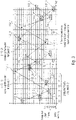
- FIG. 3 shows in detail 3 in a diagram a division of the frequency band into resources and a frequency and defined by two different channel access patterns time jump-based allocation of the resources of the frequency band.
- the ordinate describes the frequency channel indices and the abscissa describes the time slot indices.
- participants in the first communication system 102_1 can communicate wirelessly with one another based on the first channel access pattern 110_1, which specifies a frequency-hopping-based allocation of resources in the frequency band that can be used for the communication of the first communication system 102_1, while participants in the second communication system 102_2 can communicate with one another based on the second channel access pattern 110_2, which indicates a frequency hopping-based occupancy of resources of the frequency band that can be used for the communication of the second communication system 102_2, communicate wirelessly with one another, the first channel access pattern and the second channel access pattern being different (e.g. having an overlap of less than 20%, ideally having no overlap).
- the first channel access pattern and the second channel access pattern being different (e.g. having an overlap of less than 20%, ideally having no overlap).
- 3 shows an overview of all fundamentally available resources in frequency and time in the form of a grid (schematic representation of the frequency channels and time slots as well as exemplary channel access patterns), with an individual resource element in the first communication network 102_1 being determined by assigning a frequency channel index and a time slot index.
- the resources that can be occupied by the first communication network 102_1 are the resource elements identified by the reference symbol 112_1.
- the set of all resources that can be used within a communication network represents a channel access pattern 110_1.
- the channel access pattern of another communication network e.g.
- the second communication network 102_2) is in 3 entered by way of example (all resource elements identified by reference numbers 112_2, which are connected by arrows), which is not anchored in the same frequency and time grid as the first communication network 102_1 (resource elements are shifted in frequency and time from the basic grid of the first communication network 102_1).
- the design of the channel access pattern thus also means a specification of the actively usable resource reserve for this communication network (or communication system).
- Exemplary embodiments of base stations, end points and/or communication systems are described below that use channel access patterns for communication that meet at least one of the criteria a) to e) mentioned above. Furthermore, exemplary embodiments of the generation of such channel access patterns are described below.
- FIG. 4 shows a schematic block diagram of a communication system 102 with a base station 104 and a plurality of endpoints 106_1-106_4, according to an embodiment.
- the communication system 102 may include a base station and four endpoints 106_1-106_4.
- the present invention is not limited to such exemplary embodiments, rather the communication system can have one or more end points 106_1-106_n, where n is a natural number greater than or equal to one.
- the communication system may have 1, 10, 100, 1,000, 10,000, or even 100,000 endpoints.
- the communication system 102 works in an uncoordinated manner in relation to the other communication systems that use the same frequency band.
- the base station 104 can be configured to transmit a signal 120, the signal 120 having information about a channel access pattern 110, wherein the channel access pattern indicates a frequency and/or time jump-based occupancy (e.g. of resources) of the frequency band that can be used for the communication of the communication system 102 (e.g. a chronological sequence of frequency resources that can be used for the communication of the communication system (e.g. distributed over the frequency band), wherein the Information describes a state of a number sequence generator for generating a number sequence, the number sequence determining the channel access pattern.
- the channel access pattern indicates a frequency and/or time jump-based occupancy (e.g. of resources) of the frequency band that can be used for the communication of the communication system 102 (e.g. a chronological sequence of frequency resources that can be used for the communication of the communication system (e.g. distributed over the frequency band)
- the Information describes a state of a number sequence generator for generating a number sequence, the number sequence determining the channel access pattern.
- the state of the number sequence generator can be an internal state of the number sequence generator, it being possible for a number of the number sequence to be derived from the internal state of the number sequence generator.
- internal states of the number sequence generator that follow the internal state of the number sequence generator can also be determined, from which subsequent numbers in the number sequence can also be derived.
- At least one of the end points 106_1-106_4 can be configured to receive the signal 120 with the information about the channel access pattern 110, and to determine the channel access pattern 110 based on the information about the channel access pattern, the information being a state of a number sequence generator for describes generation of a sequence of numbers, the sequence of numbers determining the channel access pattern.
- the base station 104 and/or at least one of the endpoints 106_1-106_4 may be configured to pseudo-randomly determine the channel access pattern depending on the state of the sequence generator, such as using a pseudo-random mapping function.
- the base station 104 and/or at least one of the endpoints 106_1-106_4 can be designed to pseudo-randomly determine the channel access pattern depending on individual information of the communication system (eg intrinsic information of the communication system, such as a network-specific identifier).
- the channel access patterns are generated by the base station 104 and can be based on the signal with the information 120 about the channel access pattern from at least one (or all) of the in 4 Endpoints 106_1-106_4 shown are determined, for example by a respective controller (control device, control unit) 130, which is implemented in the base station 104 and/or in the endpoints 106_1-106_4.
- the channel access pattern is specified (exclusively) by the base station 104, while the end points 106_1-106_4 only “know” the channel access pattern, i.e. generate it using the same method as the base station 104.
- the following description assumes a radio transmission system (or a communication arrangement) with several independent, mutually uncoordinated communication networks, the participants of which are mutually within receiving range, so that transmission signals from participants in one network can potentially be considered as interference signals for participants in other networks.
- information data or signaling information
- base station which provides the non-coordinating participants in the network (hereinafter referred to as “terminals” or “end points”) with information about the channel access pattern used within the network can transmit.
- This information can, for example, be transmitted via regularly transmitted beacon signals, but it can also be transmitted at irregular intervals or, if necessary, dedicated to individual end devices or groups of end devices.
- the entire frequency band available for transmission is divided into a large number of individual frequency channels, which can each be accessed individually or in subsets (groups of frequency channels).
- channel access in the form of sending a signal can be done both by terminals and by the base station.
- channel access must be in an im Channel access patterns provided resource not necessarily done if, for example, no data or other information is pending for transmission.
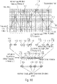
- figure 5 13 shows a schematic block diagram of a controller 130 for generating a channel access pattern, according to an embodiment of the present invention.
- the controller 130 can have a memory 132, a periodic number generator 134 for generating a periodic number sequence Z, a randomizing sequencer 136 and a frequency/time sequencer 138.
- the memory (e.g. a register) 132 can be designed to hold a network-specific identifier ID 140, e.g. a (individual) bit sequence, which does not change.
- the periodic number generator 134 can be designed to provide its state 142 or a number 142′ of the periodic sequence of numbers derived from its state.
- the randomizing allocator 136 can be designed to determine a pseudo-random number R 144 depending on the state 142 of the number sequence generator 134 or the number 142 ′ of the periodic number sequence derived therefrom and the network-specific identifier ID 140 .
- the frequency/time allocator 138 can be designed to determine frequency information f 146 and time information t 148 based on the pseudo-random number R 144 .
- the frequency information f 146 and the time information t 148 can describe or define a frequency channel and a time slot (or a frequency channel index and a time slot index) and thus a resource of the channel access pattern.
- the controller 130 can, for example - as described in 4 is indicated - implemented in the base station 104 and/or in the one or more endpoint(s) 106_1-106-4 to calculate the individual (or network individual) channel access pattern used by the communication system 102.
- figure 5 12 shows the basic structure for generating channel access patterns, according to an embodiment of the present invention.
- the channel access pattern is generated iteratively, ie the in figure 5 blocks shown are called once per generation of a single channel access information item. A channel access pattern with N channel accesses is thus generated by calling N times.
- number is used. This is generally discrete information that can be presented in different ways (e.g. in decimal form, as a binary sequence or similar).
- the network-specific identifier is a fixed number that is specified by an external entity (e.g. when configuring the network or the coordinating base station). Ideally, it differs from network to network. For example, it could be a unique, sufficiently long base station ID, unique network ID or a sufficiently long hash about it. This size is fixed and is the only one in the arrangement shown that does not vary from call to call.
- the periodic number generator 134 generates a sequence of numbers Z that is repeated periodically with the periodicity P. It has an internal state S n from which the next generated number and the next internal state S n+1 can be determined unambiguously.
- the decisive feature is that the entire periodic sequence for any time step can already be derived from a single internal state (which exists at any time step).
- a simple exemplary embodiment is, for example, a modulo P counter which periodically supplies the sequence of numbers 0,1,2...(P-1).
- a further exemplary embodiment is a deterministic random number generator (pseudo random number generator), for example implemented in the form of a feedback shift register (LFSR).
- LFSR feedback shift register
- a third embodiment is a finite field (Galois field) with P elements.
- the assignment is as random as possible, ie a mathematically correlated input sequence (consisting of ID, Z) generates an output sequence R that is as uncorrelated as possible.
- the sequence of the elements of the number R is of a pseudo-random nature. It should vary from network to network to minimize channel access pattern overlap.
- the time slots are indexed in chronologically ascending order, since "jumps back" in time are not permitted. Further information on the allocation of the time slots can be found in Section 3.
- the sequence of the 2-tuples (f,t) or (fi,ti) is based on the sequence of the elements of R and defines the channel access pattern.
- the arrangement shown generates a channel access pattern which depends both on a time-invariant, network-specific identifier and on a state-dependent (and thus time-changeable) periodic number generator (periodicity P).
- the network-specific identifier can be used to ensure that networks with different network-specific identifiers always generate different sequences of R, even if their number generator is in the same state. In this way it can be ensured that different networks do not generate identical channel access patterns and thus, in the worst case, end up in a "permanent collision" of the channel accesses.
- a terminal device To determine the channel access pattern used in the network, a terminal device requires both the network-specific identifier and the respective status of the periodic number generator.
- the end device receives the network-specific identifier when it first registers with the network. This is advantageously transmitted by means of beacon signals (beacon) sent out regularly by the base station and made accessible to all authorized terminals.
- the network-specific identifier can also be made known to the end device in the course of the initial configuration (with delivery), i.e. before the first commissioning in the network.
- the state of the periodic number generator can be communicated either in a regular beacon signal and/or in separate, dedicated state signaling resources.
- a number generator with periodicity P has P internal states, so that ⁇ log 2 ( P ) ⁇ bits must be transmitted to transmit the respective state.
- the amount of information (number of bits) transmitted per status signaling can thus be controlled by the selected periodicity of the number generator as required.
- the information transmitted for the status signaling can be transmitted in the form of a plurality of pieces of information, with the transmission being able to take place at different frequencies.
- the periodic number generator (Z) is a counter
- the more significant bits (most significant bits (MSBs)) of the counter could be separated from the less significant bits (least significant bits (LSBs)) are transmitted and also with a different frequency (e.g. less frequently).
- LSBs least significant bits
- a terminal which is aware of the state of the number generator at at least one point in time can determine the entire channel access pattern for any point in time/time slot in the future. It is thus possible for the terminal device to deactivate the transceiver unit, for example, in an energy-saving idle state and, when the transceiver unit is subsequently activated, to predict the section of the channel access pattern that is then valid from the last previously known state.
- the status information can therefore be sent by the base station at comparatively large time intervals.
- the method described here has the advantage that a comparatively large state space for the (pseudo-random) number R is spanned by the combination of a network-specific identifier and a periodic number generator. This prevents the channel access patterns of networks with different network-specific identifiers from being identical, which means that a systematic collision of the channel accesses of different networks that are not coordinated with one another can be minimized. This proves to be particularly advantageous with the Telegram Splitting Multiple Access (TSMA) method.
- TSMA Telegram Splitting Multiple Access
- a periodic number generator 134 is required. This is replaced as follows in the following exemplary embodiment.
- beacon transmission can be provided with a counter which corresponds to a beacon sequence index.
- This beacon sequence index is referred to herein as the "beacon index”.
- time slots in a time slot-based system are provided with a time slot index counter (increasing in the time direction) (see also 3 ). This is referred to herein as the "timeslot index".
- the beacon index is reset to zero at certain intervals specified in the system, so that it has a periodicity having. The same applies to the time slot index (which, for example, starts again at zero after a beacon transmission).
- 6 13 shows a schematic block diagram of a controller 130 for generating a channel access pattern, according to an embodiment of the present invention.
- the controller 130 may include a memory 132, a first buffer 135_1, a second buffer 135_2, a randomizing allocator 136, and a frequency/time allocator 138.
- the memory (e.g. a register) 132 can be designed to hold a network-specific identifier ID 140, e.g. a (individual) bit sequence, which does not change.
- the first buffer (e.g. a register) 135_1 can be designed to hold a periodic beacon index Z1 143_1.
- the second buffer (e.g. a register) 135_2 can be designed to hold a periodic time slot index Z2 143_2.
- the randomizing allocator 136 can be designed to determine a pseudo-random number R 144 as a function of the periodic beacon index Z1 143_1 , the periodic time slot index Z2 143_2 and the network-specific identifier ID 140 .
- the frequency/time allocator 138 can be designed to determine frequency information f 146 and time information t 148 based on the pseudo-random number R 144 .
- the frequency information f 146 and the time information t 148 can describe or define a frequency channel and a time slot (or a frequency channel index and a time slot index) and thus a resource of the channel access pattern.
- 6 shows a modified basic structure for generating channel access patterns with beacon index and timeslot index.
- an exemplary embodiment is shown in which, compared to that in figure 5
- the periodic number generator (output Z) 134 was replaced by the two blocks "periodic beacon index” (output Z1) 135_1 and “periodic time slot index” (output Z2) 135_2. All other blocks are functionally unchanged (the randomizing mapper now has three inputs).
- the frequency range (or frequency band) is divided into discrete frequency channels and that transmission is based on the TSMA method.
- Mobile radio channels usually have a signal attenuation that varies over the frequency. If, according to the TSMA method, a data packet is transmitted in the form of several partial data packets and the underlying mobile radio channel is not known in the transmitter, the error rate of the transmission can be reduced on average or even minimized by the individual partial data packets being transmitted over the entire frequency range as far as possible distributed (use of frequency diversity).
- a suitable method can be used ensure that there is a minimum distance between two consecutive frequency channels of the channel access pattern.
- the frequency/timing time allocator 138 (see figure 5 or 6 ) therefore be designed to determine frequency information f and time information t based on the pseudo-random number R, the frequency information f indicating a distance between two consecutive frequency channels.
- the frequency/time allocator 138 in figure 5 or 6 which independently defines absolute frequency channels from access to access on the basis of the pseudo-random number R, can alternatively also determine distances between two consecutive frequency channels.
- the frequency/time allocator 138 (see figure 5 or 6 ) be designed to determine frequency information and time information based on the pseudo-random number R, the frequency information indicating a distance ⁇ fi n between two consecutive frequency channels.
- controller 130 can have a mapper 150, which can be designed to map the distance ⁇ fi n between two consecutive frequency channels to a frequency channel index fi, for example by a combiner (e.g. adder) 152 and a delay element 154.
- a mapper 150 can be designed to map the distance ⁇ fi n between two consecutive frequency channels to a frequency channel index fi, for example by a combiner (e.g. adder) 152 and a delay element 154.
- 7 shows the generation of frequency hops with a minimum and/or maximum hop width.
- the frequency / time allocator 138 of figure 5 or 6 is now replaced by a frequency difference/point in time allocator 138, which no longer supplies absolute frequency channel indices at its immediate output, but rather frequency channel index differences.
- ⁇ fi max ⁇ fi ⁇ fi min for ⁇ fi>0
- ⁇ fi max ⁇ (- ⁇ fi) ⁇ fi min for ⁇ fi ⁇ 0.
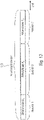
- FIG. 12 shows in a diagram a frequency-based and time jump-based occupancy of the resources 112 of the frequency band defined by a channel access pattern 110 and a projection of the channel access pattern 110 onto a time axis, according to an embodiment of the present invention.
- the ordinate describes the frequency channel indices and the abscissa describes the time slot indices.
- 9 shows in the upper part an example of a channel access pattern 110 in the dimensions of frequency and time (resource elements 112) and in the lower part its projection onto the time dimension. It can be seen that not every time slot is part of the channel access pattern 110.
- the time dimension in the form of the time slot index
- the time dimension is therefore also available for the generation of a pseudo-random channel access pattern 110 .
- the activity rate thus determines the (temporal) density of the resources 112 offered in the channel access pattern 110.
- the time slots selected for a given activity rate for channel access can be pseudo-randomly selected from a suitable part of the pseudo-random number R (see figure 5 or 6 ) are determined.
- an integer r n can be derived from the associated pseudo-random number R n , which can assume values between r min and r max , ie r min ⁇ r n ⁇ r max .
- R n pseudo-random number
- FIG. 10 shows in detail 10 in a diagram, resource elements 112 of a channel access pattern 110 projected onto a time axis, resulting in unused time slots, according to an embodiment.
- 10 12 shows an example sequence of used and unused time slots, according to an embodiment.
- the method presented in the above exemplary embodiment has the advantage that minimum and maximum distances between the time slots active in the channel access pattern 110 can be specified.
- the specification of minimum distances can be particularly advantageous for battery-powered devices in which pauses in transmission of a certain Minimum length between two consecutive transmissions (recovery phase) increase battery life.
- groups of consecutive time slots are specified periodically, within each of which an active time slot of the channel access pattern is placed. This is for an activity rate of 1/4 (25%) in 11 shown as an example.
- 11 12 shows an example sequence of used and unused time slots, according to an embodiment.
- the time slots can be grouped into clusters 114 (in the example of 11 of length 4) are grouped. Exactly one time slot of the channel access pattern 110 is placed in each cluster 114 .
- the position of the time slots included in the channel access pattern 110 within the cluster 114 can be determined by a displacement v n which is derived from the pseudo-random number R n and which can assume integer values between 0 and (cluster length-1).
- areas that cannot be used can be introduced between the clusters 114 . These can consist of one or more time slots, as shown in 12 is illustrated.
- 12 shows an exemplary sequence of used and unused time slots with non-allocable time slots, according to an embodiment.
- the permissible range of the shift variable v n is reduced to the value range from 0 to (cluster length-1-length of the non-assignable area) due to the time slots that cannot be used.
- the clusters 114 may need to be of different lengths to achieve the desired activity rate.
- the value range of v n varies according to the respective cluster length. For example, to set an activity rate of 40%, clusters of length two and length three can alternate.
- Data packets that are to reach the recipient as quickly as possible require channel accesses that follow each other as closely as possible during transmission, i.e. a comparatively high activity rate in the channel access pattern.
- the activity rate ie the frequency of channel access
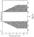
- a channel access pattern can be designed in such a way that it has areas with different activity rates. This is in 13 shown as an example.
- end devices can then, for example, transmit in the area that is suitable for them.
- FIG. 13 shows in detail 13 a temporal division of a channel access pattern 110 into areas of different activity rates A 1 , A 2 and A 3 , according to an embodiment.
- 13 shows an example of a channel access pattern with three areas of different activity rates within the channel access pattern 110.
- Networks (or communication systems) 102 may have different load situations at different times.
- the actively usable resource reserve for this network can be defined via the design of the channel access pattern 110 (i.e. its activity rate or average temporal density).
- a battery-operated base station e.g. in a PAN network, possibly in repeater mode
- PAN network possibly in repeater mode
- a battery-operated base station which operates the receiver during all active resources of the channel access pattern and thus uses energy.
- the mean activity rate ie the temporal density of the resources offered by the channel access pattern 110, to the prevailing load conditions. If the activity rate of the channel access pattern 110 is changed, this is signaled accordingly to the participants in the network, for which e.g. the beacon signal (or also dedicated signaling resources) comes into question.
- a terminal device 106 If a terminal device 106 is in a longer idle state (power-saving mode), it may happen that it does not receive the signaling information sent out by the base station 104 during the idle state about a possibly changed channel access pattern. In such a scenario, it may make sense for a channel access pattern 110 to provide a minimum pool of (basic) resources that are available at all times and without special signaling, and an additional pool of resources that can be added depending on the load and is subject to appropriate signaling .
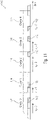
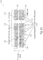
- Resources that are additionally added to the channel access pattern in the above sense can, for example, be arranged chronologically after the basic resources or also be arranged interleaved with them in the time/frequency grid, as is shown in 14 is shown.
- FIG. 14 shows in detail 14 in a diagram a defined by a channel access pattern 110 frequency and time jump-based occupancy of the resources 112 of the frequency band, where the channel access pattern 110 additionally has resources 112* that can be activated on demand, according to an embodiment of the present invention.
- the ordinate describes the frequency channel indices and the abscissa describes the time slot indices.
- 14 shows an example of entangled basic and additional resources.
- users may be able to decide for themselves which frequency ranges they use within the frequency band without regulatory restrictions. This can mean that certain areas of the available frequency band are occupied more by external users than others and are therefore exposed to greater interference.
- a base station 104 detects such a medium or long-term asymmetric utilization of the frequency band (e.g. through frequency-channel signal-to-interference power estimates based on received signals), the above-average heavily occupied area of the frequency band can be avoided for use by its own network, by not including the associated frequency channels in the channel access pattern. This is in the frequency/timing allocator (see figure 5 or 6 ) must be taken into account and is signaled to all network participants in a suitable manner.
- the group of frequency channels excluded can be described, for example, by a corresponding starting and ending frequency channel index or by a starting frequency channel index and a following channel number.
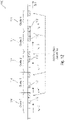
- FIG. 15 shows in a diagram a frequency-based and time jump-based occupancy of the resources 112 of the frequency band defined by a channel access pattern 110, wherein a frequency range 115 of the frequency band that is regularly subject to more interference is not occupied by the channel access pattern 110, according to an embodiment of the present invention.
- the ordinate describes the frequency channel indices and the abscissa describes the time slot indices.
- 15 shows an example for excluding strongly disturbed frequency channels from the channel access pattern.
- a base station 104 may be able to receive on a number of frequency channels at the same time (frequency channel bundling).
- frequency channel bundling it is advantageous, especially in the case of systems with higher loads, to increase the number of resource elements offered within the network in the frequency dimension accordingly and to include several frequency channels within a time slot in the channel access pattern, as is shown in 16 is shown.
- a channel access pattern 110 defines a frequency-based and time-jump-based occupancy of the resources 112 of the frequency band, with resources 112 being bundled in the frequency domain, according to an embodiment.
- the ordinate describes the frequency channel indices and the abscissa describes the time slot indices.
- 16 shows an exemplary representation of the channel access pattern 110 when bundling three adjacent frequency channels to form resource clusters.
- the bundling of three frequency channels is shown as an example.
- Each group of resource elements of a time slot can be referred to as a "resource cluster”.
- the channel access pattern 110 can be supplemented by information about the number of frequency channels that constitute a resource cluster.
- the frequency channels grouped into resource clusters do not necessarily have to be directly adjacent.
- the following shows how one or more participants in a communication system 102 using a relative channel access pattern to a Selection of the resources released by the network-specific channel access pattern 110 for the communication system 102 can access.
- FIG. 17 shows a schematic block diagram of a communication system 102 with a base station 104 and two endpoints 106_1-106_2, according to an embodiment of the present invention.
- the communication system 102 shown has, for example, a base station 104 and two endpoints 106_1-106_2.
- the present invention is not limited to such exemplary embodiments, rather the communication system 102 can have one or more endpoints 106_1-106_n, where n is a natural number greater than or equal to one.
- the communication system may have 1, 10, 100, 1,000, 10,000, or even 100,000 endpoints.
- the communication system 102 works in an uncoordinated manner in relation to the other communication systems that use the same frequency band.
- the base station 104 is designed to transmit a signal 120, the signal 120 having information about a network-specific channel access pattern 110, the network-specific channel access pattern 110 having a frequency and /or indicates time jump-based occupancy of resources of the frequency band, while the end points 106_1-106_2 are designed to receive the signal 120 and to determine the network-specific channel access pattern 110 based on the information about the network-specific channel access pattern (see e.g figure 5 and 6 ).
- the participants e.g. base station 104 and endpoint 106_1
- the participants can use a relative channel access pattern which indicates which of the network-specific channel access patterns 110 for the communication of the Communication system 102 released or usable resources are actually to be used for the transmission of data.
- the base station 104 may be configured to transmit (e.g., transmit to and/or receive from endpoint 106_1) data 160 (e.g., a signal including data 160) using a relative channel access pattern. wherein the relative channel access pattern indicates an occupancy of resources to be used for the transmission from the usable frequency and/or time jump-based occupancy of resources of the network-specific channel access pattern 110 .
- the endpoint 106_1 may be configured to transmit (e.g., receive from and/or transmit to the base station 104) data 160 (e.g., a signal comprising the data 160) using the relative channel access pattern, where the relative Channel access pattern indicates an allocation of resources to be used for the transmission from the usable frequency and/or time jump-based allocation of resources of the network-specific channel access pattern.
- data 160 e.g., a signal comprising the data 160
- the relative Channel access pattern indicates an allocation of resources to be used for the transmission from the usable frequency and/or time jump-based allocation of resources of the network-specific channel access pattern.
- a different relative channel access pattern can be used for mutual communication between other participants (e.g. base station 104 and endpoint 106_2) of the communication system 102, which indicates which of the resources released or usable by the network-specific channel access pattern 110 for the communication of the communication system 102 are actually available for the transmission of the data where the relative channel access pattern (e.g. from endpoint 106_1) and the other relative channel access pattern (e.g. from endpoint 106_2) are different.
- the relative channel access pattern e.g. from endpoint 106_1
- the other relative channel access pattern e.g. from endpoint 106_2
- the base station 104 may be further configured to transmit data 162 (e.g. a signal with the data 162) using a different relative channel access pattern (e.g. to send to the other endpoint 106_2 and/or from the other endpoint 106_2 to receive), wherein the other relative channel access pattern indicates an allocation of resources to be used for the transmission from the usable frequency and/or time jump-based allocation of resources of the network-specific channel access pattern, the relative channel access pattern and the other relative channel access pattern being different.
- data 162 e.g. a signal with the data 162
- a different relative channel access pattern e.g. to send to the other endpoint 106_2 and/or from the other endpoint 106_2 to receive
- the other relative channel access pattern indicates an allocation of resources to be used for the transmission from the usable frequency and/or time jump-based allocation of resources of the network-specific channel access pattern, the relative channel access pattern and the other relative channel access pattern being different.
- the other endpoint 106_2 can be configured to transmit data 162 (e.g. a signal with the data 162) using the other relative channel access pattern (e.g. to receive from the base station 104 and/or to transmit to the base station 104), wherein the other relative channel access pattern indicates an occupancy of resources to be used for the transmission from the usable frequency and/or time jump-based occupancy of resources of the network-specific channel access pattern, the relative channel access pattern and the other relative channel access pattern being different.
- data 162 e.g. a signal with the data 162
- the other relative channel access pattern indicates an occupancy of resources to be used for the transmission from the usable frequency and/or time jump-based occupancy of resources of the network-specific channel access pattern, the relative channel access pattern and the other relative channel access pattern being different.
- the relative channel access patterns can be determined by the participants (e.g. the base station 104 and at least one of the endpoints 106_1-106_2), for example by the controller 130 implemented in the participants.
- the following exemplary embodiments refer to the exemplary embodiments described in Section A, which, when there are several uncoordinated radio networks (e.g. LPWAN, PAN) in mutual reception range, design access to a shared frequency band in such a way that the cross-network, mutual interference of the participants or their adverse effects on transmission security are reduced or even minimized.
- LPWAN low-power wide area network
- PAN personal area network
- TSMA Telegram Splitting Multiple Access
- base station referred to as “PAN coordinator” in the context of the IEEE standard [2]
- PAN coordinator provides the non-coordinating participants of the network
- endpoints can convey information about the channel access pattern used within the network.
- the channel access patterns described above define a set of radio resources (resource elements) that are fundamentally available for transmission within a network for a specific period of time. you define thus the range of resources specified by the base station (valid for the period under consideration) to which the end devices can access.
- competition-free access a terminal is assigned uniquely specified radio resources for exclusive use by the coordinating entity (base station).
- the coordinating entity base station
- the terminal has a range of radio resources available, from which the terminal uses its own initiative, i.e. without individual resource allocation, if required. It is characteristic here that other end devices can also access the same offer, so that conflicts can arise when accessing the shared radio resources. The aim is to reduce or even avoid these conflicts as far as possible.
- Exemplary embodiments thus deal with techniques that make the distribution of the existing resources (which have been defined by the base station) as effective as possible, so that the interference between the participants within the network is reduced or even minimized.
- Exemplary embodiments provide that there is a stock of relative channel access patterns known to both the base station and the terminals of the network, from which the terminal uses one, for example, for each transmission.
- the selection of a relative channel access pattern from the available pool can be based on various criteria and is described in more detail below.
- the actively used relative channel access pattern of a network participant thus consists of a subset of the network-specific channel access pattern.
- the use of the exemplary embodiments described here is particularly advantageous for data transmission using the TSMA method, in which a data packet is transmitted divided into a number of partial data packets.
- the following representation assumes that the frequency band is divided into a number of discrete frequency channels and that the accesses within a network are also discretized in terms of time in the form of time slots .
- FIG. 18 shows in a diagram a frequency- and time-jump-based usable occupancy of resources 112 of the frequency band indicated by a network-specific channel access pattern 110, an occupancy of resources 118 to be used for transmission indicated by a relative channel access pattern 116 from the usable occupancy of resources 112 of the network-specific channel access pattern 110, as well as projections of the channel access patterns 110, 116 on time axes before and after removal of unused resources (eg time slots), according to an embodiment.
- the ordinate describes the frequency channel indices and the abscissa describes the time slot indices.
- the network-specific channel access pattern 110 defines the distribution of the resources 112 of the frequency band (e.g. each defined by time slot and frequency channel, or time slot index and frequency channel index), which are used by the communication system 102 and thus by the participants (base station 104 and end points 106_1-106_2) of communication system 102 can be used for mutual communication, while relative channel access pattern 116 indicates those resources 118 from usable resources 112 that are used by a subset of the participants (e.g., a limited group of participants, e.g., by two participants, such as base station 104 and Endpoint 106_1) of the communication system 102 are actually used for mutual communication.
- a subset of the participants e.g., a limited group of participants, e.g., by two participants, such as base station 104 and Endpoint 106_1 of the communication system 102 are actually used for mutual communication.
- 18 shows a schematic exemplary representation of the network-specific and relative channel access pattern (hierarchical structure of channel access). while showing 18 in the upper part, for example, the distribution of the radio resources in a discrete time/frequency grid into a large number of resource elements.
- a resource element is described by a frequency channel index and a time slot index.
- a network-specific channel access pattern 110 is illustrated, which is highlighted by resource elements 112 which are symbolically connected to one another by arrows.
- This network-specific channel access pattern 110 represents the supply of resource elements 122 that a network (or communication system) 102 makes available. In this example, a signal transmission is only possible on one frequency channel in a time slot.
- the two-dimensional representation is projected onto the time axis and all the time slots that are not occupied in the network-specific channel access pattern 110 are removed, the result is the "available resources" 112 according to the above representation.
- the time indexing can advantageously be done here by a relative time slot index, which is relative to the network-specific channel access pattern .
- a relative channel access pattern 116 is shown as an example, which defines a subset of the available resources (possibly also all of them). That in selected example effectively resulting channel access pattern (ie the hierarchical combination of network-specific and relative channel access pattern) is in all areas of 18 denoted by resource elements 118.
- the relative channel access pattern with its relative time slot index can be calculated back to the original discrete time grid using the mean activity rate A defined in Section A. This average activity rate is defined as the average ratio of time slots used for channel access to the total maximum available time slots. If each time slot is used, the activity rate A is therefore 1 (100%).
- a base station 102 may be able to receive on a number of frequency channels at the same time (frequency channel bundling).
- frequency channel bundling it is advantageous, particularly in the case of systems with higher loads, to correspondingly increase the number of resource elements offered within the network in the frequency dimension and to include a number of frequency channels within a time slot in the network-specific channel access pattern 110 . this is in 19 shown.
- FIG. 19 shows in detail 19 in a diagram, a frequency- and time-jump-based usable allocation of resources 112 of the frequency band bundled in the frequency domain, indicated by a network-specific channel access pattern 110, an allocation of resources 118 to be used for the transmission, indicated by a relative channel access pattern 116, from the usable allocation of resources 112 of the network-specific Channel access pattern 110, and projections of the channel access pattern 110, 116 on time axes before and after removal of unused resources (e.g. time slots).
- the ordinate describes the frequency channel indices and the abscissa describes the time slot indices.
- the network-specific channel access pattern 110 in the frequency direction is a bundling of resources 112, ie a plurality of adjacent resources 112 (e.g. frequency channels or frequency channel indices) of the frequency band, with the relative channel access pattern 116 in the frequency direction at most one Subset (e.g. at most one resource, i.e. one or no resource) of the plurality of neighboring resources 112 of the network-specific channel access pattern 110 indicates.
- 19 shows a schematic exemplary representation of the network-specific channel access pattern 110 and the relative channel access pattern 116 with gapless frequency channel bundling.
- the occupancy of the (in the example: three) frequency channels is also available as a degree of freedom.
- FIG. 20 shows in a diagram a frequency- and time-jump-based usable allocation of resources 112 of the frequency band that are spaced apart from one another in the frequency domain, indicated by a network-specific channel access pattern 110, an allocation of resources 118 to be used for transmission, indicated by a relative channel access pattern 116, from the usable allocation of resources 112 of the network-specific channel access pattern 110, an allocation of resources 119 to be used for the transmission, specified by another relative channel access pattern 117, from the usable allocation of resources 112 of the network-specific channel access pattern 110, and projections of the channel access patterns 110, 116, 117 on time axes before and after removal of unused ones Time slots or frequency channels, according to an embodiment.
- the ordinate describes the frequency channel indices and the abscissa describes the time slot indices.
- the network-specific channel access pattern 110 in the frequency direction is a bundling of resources 112, ie a plurality of spaced-apart resources 112 (e.g. frequency channels or frequency channel indices) of the frequency band, with the relative channel access pattern 116 in the frequency direction at most indicates a subset (e.g. at most one resource, i.e. one or no resource) of the plurality of spaced-apart resources 112 of the network-specific channel access pattern 110, and wherein that other relative channel access pattern 117 in the frequency direction indicates at most a subset (e.g. at most one resource, ie one or no resource) of the plurality of spaced-apart resources 112 of the network-specific channel access pattern 110, the relative channel access pattern 116 and the other relative channel access pattern 117 being different.
- resources 112 e.g. frequency channels or frequency channel indices
- 20 shows a schematic exemplary representation of the network-specific channel access pattern 110 and the relative channel access pattern 116 in the case of gapped frequency channel bundling.
- this frequency channel bundling is that, as shown in the in 20 additionally shown relative channel access pattern 117 of a second participant (e.g. user) significantly less adjacent channel interference (the channel separation of two directly adjacent channels is always problematic due to the limited filter effect, especially when one channel is received with a significantly stronger reception power than the adjacent channel) as in 19 occurs.
- a second participant e.g. user
- the advantage of in the 19 and 20 The bundling described above consists in giving access to the radio resources to more terminals within the network and within a given period of time (higher load). Alternatively, with a given load, the probability of channel access collisions can be reduced by channel bundling, since a given access volume is distributed over more potential resource elements (reduced mutual interference between the participants within the network).
- the advantage of frequency channel bundling over the use of more time slots is also greater energy efficiency, since the receiver switches on the receiver for fewer time slots given the same range of resource elements.
- a terminal has the ability to transmit on several frequency channels simultaneously, this can be provided for in the relative channel access pattern. This is illustrated in the figure below, which is limited only to the relative channel access pattern (corresponding to the lower parts of 19 and 20 ).
- 21 shows in a diagram a projection of a network-specific channel access pattern 110 and a relative channel access pattern 116 onto the time axis after the removal of unused frequency channels and time slots, the relative channel access pattern 116 in the frequency direction for at least part of the time jumps several of the resources 112 available in the frequency direction are occupied.
- the ordinate describes the relative frequency channel indices and the abscissa describes the relative time slot indices.
- 21 shows in a diagram a relative channel access pattern 116 in the case of frequency channel bundling with simultaneous transmission (eg transmission) on a plurality of frequency channels.
- the signal is generated on each frequency channel with an identical symbol rate.
- this area referred to below as a “resource cluster”
- Different symbol rates and/or a different number of symbols can be assigned to these sub-resources, as shown in 22 is illustrated.
- FIG. 22 shows in a diagram a frequency- and time-jump-based usable occupancy specified by a network-specific channel access pattern 110 of resources 112 of the frequency band bundled in the frequency domain to form blocks (or clusters) 113, with different parts 111_1-111_4 of the block 113 of related resources 112 having different symbol rates and/or or are assigned different numbers of symbols, according to one embodiment.
- the ordinate describes the frequency channel indices and the abscissa describes the time slot indices.
- 22 shows the formation of resource clusters 113 with sub-resources 111_1-111_4 with different symbol rates and number of symbols per time slot (example).
- each resource cluster 113 is divided into four independent sub-resources “A” (111_1), “B” (111_2), “C” (111_3), “D” (111_4), in which different multiples of the symbol rate f s and the number of symbols N s are used.
- A 111_1
- B 111_2
- C 111_3
- D 111_4
- different multiples of the symbol rate f s and the number of symbols N s are used.
- two consecutive accesses can take place in a time slot, for example due to the shortened symbol duration by two different participants. this is in 22 the case for the chronologically consecutive sub-resources “B” (111_2) and “C” (111_3).
- the advantage of this procedure is that within the network-specific channel access pattern 110 resources can be occupied with different symbol rates and thus transmission bandwidths as required.
- resource clusters 113 formed by frequency channel bundling can be divided into individual sub-resources in a variety of ways.
- the symbol rates used in this case do not necessarily (as in the selected example) have to be integer multiples of a basic symbol rate. The same applies to the number of symbols in the sub-resources.
- Data packets that are to reach the recipient as quickly as possible require channel accesses that follow each other as closely as possible during transmission, i.e. a comparatively high activity rate A in the network-specific channel access pattern, as described in section A.
- transmission security e.g. high robustness against external interference
- distribution of the transmission over a longer period of time can be advantageous, i.e. a comparatively low activity rate A in the network-specific channel access pattern can be beneficial.
- a temporally equalized energy consumption from the battery time-stretched transmission activity
- 23 12 is a diagram showing a projection of a network-specific channel access pattern 110 and a relative channel access pattern 116 with D resources 112 onto the time axis after removing unused resources (frequency channels and time slots), according to an embodiment.
- the ordinate describes the relative frequency channel indices and the abscissa describes the relative time slot indices.
- the number of available resource elements is to be determined based on the total frame duration T frame and the network-specific activity rate A from section A and the time duration T RE for a resource element.
- T Frame T RE • (Z / A) it depends on the application.
- T Frame should not be greater than 500 ms.
- the duration of a resource frame can easily assume values of 5 to 10 seconds.
- the network-specific activity rate A from section A is also influenced by the use case.
- duration T RE of a partial data packet or resource element still applies.
- a symbol rate f S of, for example, around 2500 sym/s and a number of 30 to 80 symbols per partial data packet values of 12 to 32 ms result for T RE .
- the number Z of resources available in the time direction can be determined from the application-specific specifications for T Frame , T RE and A. Together with the F specified frequency channels, the total resources available per resource frame then result. As in the in 24 shown in the table shown, these values can differ significantly depending on the application.
- FIG. 24 shows in detail 24 in a table a resource calculation for various exemplary use cases.
- the second design step applies the length D of each channel access pattern and the available F ⁇ Z resource elements that To determine the number M of different channel access patterns.
- M Max Z ! ⁇ f D / Z ⁇ D ! ⁇ D ! different channel access patterns of length D that differ in at least one resource element.
- M max would again increase massively.
- the number D of sub-packets should be selected as large as possible, since then the robustness to interference from other participants is greatest, regardless of whether they come from your own network or from other networks.
- a data packet is usually broken down into 10 to 30 partial data packets. If a transmission time corresponding to this number of partial data packets is not available, as is the case with some latency-critical applications, the value of D can also be smaller.
- M 1024
- 25 shows in a diagram simulation results of the packet error rate for different channel access pattern lengths M as a function of the number of simultaneously active terminals with 360 resource elements.
- the ordinate describes the packet error rate PER and the abscissa describes the number of N terminals (eg end points) active simultaneously in the resource frame.
- N 2 terminals
- 26 shows in a diagram simulation results of the packet error rate for different channel access pattern lengths M as a function of the number of simultaneously active terminals with 60 resource elements.
- the ordinate describes the packet error rate PER and the abscissa describes the number of N terminals (eg end points) active simultaneously in the resource frame.
- M max 10 14
- M 1024 proves to be sensible. If the value of M max falls below the threshold of 10 14 , M can be reduced accordingly, with simulations having to be used to check to what extent the PER performance still satisfies the requirements. for very large values of M max , M can certainly assume values that are even greater than 1024. This can be determined by appropriate simulations.
- the number M of different channel access patterns and their length D was determined.
- the individual channel access patterns are determined by means of a random number generator, as a result of which there is as little connection or similarity as possible between the M individual patterns.
- this usually means a very large detection effort.
- an attempt is made in the third design step to give the channel access patterns structural properties such as clustering or repeating patterns in order to significantly reduce the computational complexity on the receiver side.
- the PER performance, such as in the 25 and 26 shown should not deteriorate as much as possible.
- One possibility is to subdivide the resource frame into clusters 114 of the same length L, as shown in 27 is shown.
- FIG. 2 shows a flow diagram of a method 200 for operating an endpoint of a communication system, wherein the communication system communicates wirelessly in a frequency band which is used by a plurality of communication systems for communication.
- the method 200 includes a step of receiving a signal, the signal having information about a network-specific channel access pattern, the network-specific channel access pattern indicating a usable frequency and/or time jump-based occupancy of resources of the frequency band for the communication of the communication system.
- the method 200 further includes a step 204 of transmitting data using a relative channel access pattern, the relative channel access pattern specifying an allocation of resources to be used for the transmission from the usable frequency and/or time jump-based allocation of resources of the network-specific channel access pattern.
- the method 210 includes a step 212 of sending a signal, the signal having information about a network-specific channel access pattern, the network-specific channel access pattern indicating a usable frequency and/or time jump-based occupancy of resources of the frequency band for the communication of the communication system.
- the method 210 further includes a step 214 of transmitting data using a relative channel access pattern, the relative channel access pattern specifying an allocation of resources to be used for the transmission from the usable frequency and/or time jump-based allocation of resources of the network-specific channel access pattern.
- the method 220 includes a step 222 of determining a network-specific channel access pattern, the network-specific channel access pattern indicating a usable for the communication of the communication system frequency and / or time jump-based occupancy of resources of the frequency band. Furthermore, the method 220 includes a step 224 of determining a relative channel access pattern, wherein the relative channel access pattern indicates an allocation of resources to be used for a transmission of data of the subscriber from the usable frequency and/or time jump-based allocation of resources of the network-specific channel access pattern.
- Exemplary embodiments are used in systems for radio transmission of data from terminals to a base station or from one or more base stations to terminals.
- a system can be a Personal Area Network (PAN) or a Low Power Wide Area Network (LPWAN), where the end devices can be battery-powered sensors (sensor nodes), for example .
- PAN Personal Area Network
- LPWAN Low Power Wide Area Network
- sensors sensors
- Exemplary embodiments are aimed at applications in which a message (data packet) is transmitted in a radio network in several partial data packets (so-called telegram splitting method, English Telegram Splitting [1]) and in which several mutually uncoordinated radio networks access common radio resources (e.g. common frequency band). .
- the exemplary embodiments described here can be used to transmit data based on the telegram splitting method between the users of the communication system.
- data such as a telegram or data packet
- data packet is divided into a plurality of sub-data packets (or sub-data packets, or sub-packets) and the sub-data packets are split using a time and/or frequency hopping pattern in time and/or or distributed in frequency from one participant to another participant (e.g. from the base station to the endpoint, or from the endpoint to the base station) of the communication system, with the participant receiving the sub-data packets reassembling (or combining) them to to receive the data package.
- Each of the sub data packets contains only part of the data package.
- the data packet can also be channel-coded, so that not all of the sub-data packets, but rather only some of the sub-data packets, are required for error-free decoding of the data packet.
- the sub-data packets can be distributed in a subset (e.g. a selection) of the available resources of the network-specific channel access pattern.
- the sub-packets can be transmitted based on the relative channel access pattern, i.e. in the resources of the relative channel access pattern. For example, one sub-data packet can be transmitted per resource.
- aspects have been described in the context of a device, it is understood that these aspects also represent a description of the corresponding method, so that a block or a component of a device is also to be understood as a corresponding method step or as a feature of a method step. Similarly, aspects described in connection with or as a method step also constitute a description of a corresponding block or detail or feature of a corresponding device.
- Some or all of the method steps may be performed by hardware apparatus (or using a hardware apparatus), such as a microprocessor, a programmable computer, or an electronic circuit. In some embodiments, some or more of the essential process steps can be performed by such an apparatus.
- embodiments of the invention may be implemented in hardware or in software. Implementation can be performed using a digital storage medium such as a floppy disk, DVD, Blu-ray Disc, CD, ROM, PROM, EPROM, EEPROM or FLASH memory, hard disk or other magnetic or optical memory, on which electronically readable control signals are stored, which can interact or interact with a programmable computer system in such a way that the respective method is carried out. Therefore, the digital storage medium can be computer-readable.
- a digital storage medium such as a floppy disk, DVD, Blu-ray Disc, CD, ROM, PROM, EPROM, EEPROM or FLASH memory, hard disk or other magnetic or optical memory, on which electronically readable control signals are stored, which can interact or interact with a programmable computer system in such a way that the respective method is carried out. Therefore, the digital storage medium can be computer-readable.
- Some embodiments according to the invention thus include a data carrier that has electronically readable control signals that are capable of a programmable Computer system to interact in such a way that one of the methods described herein is performed.
- embodiments of the present invention can be implemented as a computer program product with a program code, wherein the program code is effective to perform one of the methods when the computer program product runs on a computer.
- the program code can also be stored on a machine-readable medium, for example.
- exemplary embodiments include the computer program for performing one of the methods described herein, the computer program being stored on a machine-readable carrier.
- an exemplary embodiment of the method according to the invention is therefore a computer program that has a program code for performing one of the methods described herein when the computer program runs on a computer.
- a further exemplary embodiment of the method according to the invention is therefore a data carrier (or a digital storage medium or a computer-readable medium) on which the computer program for carrying out one of the methods described herein is recorded.
- the data carrier, digital storage medium, or computer-readable medium is typically tangible and/or non-transitory.
- a further exemplary embodiment of the method according to the invention is therefore a data stream or a sequence of signals which represents the computer program for carrying out one of the methods described herein.
- the data stream or sequence of signals may be configured to be transferred over a data communications link, such as the Internet.
- Another embodiment includes a processing device, such as a computer or programmable logic device, configured or adapted to perform any of the methods described herein.
- a processing device such as a computer or programmable logic device, configured or adapted to perform any of the methods described herein.
- Another embodiment includes a computer on which the computer program for performing one of the methods described herein is installed.
- a further exemplary embodiment according to the invention comprises a device or a system which is designed to transmit a computer program for carrying out at least one of the methods described herein to a recipient.
- the transmission can take place electronically or optically, for example.
- the recipient may be a computer, mobile device, storage device, or similar device.
- the device or the system can, for example, comprise a file server for transmission of the computer program to the recipient.
- a programmable logic device e.g., a field programmable gate array, an FPGA
- a field programmable gate array may cooperate with a microprocessor to perform any of the methods described herein.
- the methods are performed on the part of any hardware device. This can be hardware that can be used universally, such as a computer processor (CPU), or hardware that is specific to the method, such as an ASIC.
- the devices described herein may be implemented, for example, using hardware apparatus, or using a computer, or using a combination of hardware apparatus and a computer.
- the devices described herein, or any components of the devices described herein may be implemented at least partially in hardware and/or in software (computer program).
- the methods described herein may be implemented, for example, using hardware apparatus, or using a computer, or using a combination of hardware apparatus and a computer.
Landscapes
- Engineering & Computer Science (AREA)
- Computer Networks & Wireless Communication (AREA)
- Signal Processing (AREA)
- Quality & Reliability (AREA)
- Computer Security & Cryptography (AREA)
- Mobile Radio Communication Systems (AREA)
Claims (15)
- Point d'extrémité (106_1) d'un système de communication (102),dans lequel le système de communication (102) communique sans fil dans une bande de fréquences qui est utilisée pour la communication par une pluralité de systèmes de communication,dans lequel le point d'extrémité (106_1) est conçu pour recevoir un signal (120), dans lequel le signal (120) présente une information sur un modèle d'accès au canal spécifique au réseau (110), dans lequel le modèle d'accès au canal spécifique au réseau (110) indique une occupation de ressources (112) de la bande de fréquences à base de sauts en fréquence et dans le temps utilisable pour la communication du système de communication (102),dans lequel le point d'extrémité (106_1) est conçu pour transmettre les données (160) à l'aide d'un modèle d'accès au canal (116) relatif, dans lequel le modèle d'accès au canal (116) relatif indique une occupation de ressources (118) à utiliser pour la transmission parmi l'occupation de ressources (112) à base de sauts en fréquence et dans le temps utilisable du modèle d'accès au canal spécifique au réseau (110),dans lequel l'information décrit un état (142) d'un générateur de séquence de numéros (134) destiné à générer une séquence de numéros ou dans lequel l'information décrit un numéro (143_1, 143_2) d'une séquence de numéros, dans lequel la séquence de numéros détermine le modèle d'accès au canal (110),dans lequel l'occupation de ressources (118) du modèle d'accès au canal (116) relatif à utiliser pour la transmission est une quantité partielle de l'occupation de ressources (112) à base de sauts en fréquence et dans le temps utilisable du modèle d'accès au canal spécifique au réseau (110).
- Point d'extrémité (106_1) selon l'une des revendications précédentes,dans lequel le modèle d'accès au canal (116) relatif diffère d'un autre modèle d'accès au canal (117) relatif sur base duquel un autre abonné du système de communication (102) transmet les données,dans lequel l'autre modèle d'accès au canal (117) relatif indique une occupation de ressources (119) à utiliser pour la transmission par l'autre abonné parmi l'occupation de ressources (112) à base de sauts en fréquence et dans le temps utilisable du modèle d'accès au canal spécifique au réseau (110).
- Point d'extrémité (106_1) selon l'une des revendications précédentes,
dans lequel le modèle d'accès au canal spécifique au réseau (110) indique l'occupation de ressources à base de sauts en fréquence et dans le temps (112) de la bande de fréquences en canaux de fréquence et créneaux de temps associés ou en indices de canal de fréquence et indices de créneau de temps associés utilisable pour la communication du système de communication (102). - Point d'extrémité (106_1) selon l'une des revendications précédentes,dans lequel le point d'extrémité (106_1) est conçu pour sélectionner le modèle d'accès au canal (116) relatif parmi un ensemble de M modèles d'accès au canal relatifs,dans lequel les M modèles d'accès au canal relatifs indiquent une occupation de ressources à utiliser pour la transmission parmi l'occupation de ressources (112) à base de sauts en fréquence et dans le temps utilisable du modèle d'accès au canal spécifique au réseau (110),dans lequel les M modèles d'accès aux canaux relatifs sont différents.
- Point d'extrémité (106_1) selon l'une des revendications précédentes,
dans lequel le point d'extrémité (106_1) est conçu pour transmettre, comme données (160), un paquet de données qui est divisé en une pluralité de sous-paquets de données selon le modèle d'accès au canal relatif, dans lequel la pluralité de sous-paquets de données ne présentent, chacun, qu'une partie du paquet de données. - Station de base (104) d'un système de communication (102),dans laquelle le système de communication (102) communique sans fil dans une bande de fréquences qui est utilisée pour la communication par une pluralité de systèmes de communication,dans laquelle la station de base (104) est conçue pour transmettre un signal (120), dans laquelle le signal (120) présente une information sur un modèle d'accès au canal spécifique au réseau (110), dans laquelle le modèle d'accès au canal spécifique au réseau (110) est une occupation de ressources de la bande de fréquences à base de sauts en fréquence et dans le temps utilisable pour la communication du système de communication (102),dans laquelle la station de base (104) est conçue pour transmettre les données (160) à l'aide d'un modèle d'accès au canal (116) relatif, dans laquelle le modèle d'accès au canal (116) relatif indique une occupation de ressources (118) à utiliser pour la transmission parmi l'occupation de ressources (112) à base de sauts en fréquence et dans le temps utilisable du modèle d'accès au canal spécifique au réseau,dans laquelle l'information décrit un état (142) d'un générateur de séquence de numéros (134) destiné à générer une séquence de numéros ou dans laquelle l'information décrit un numéro (143_1, 143_2) d'une séquence de numéros, dans laquelle la séquence de numéros détermine le modèle d'accès au canal (110),dans laquelle l'occupation de ressources (118) du modèle d'accès au canal (116) relatif à utiliser pour la transmission est une quantité partielle de l'occupation de ressources (112) à base de sauts en fréquence et dans le temps utilisable du modèle d'accès au canal spécifique au réseau (110).
- Station de base (104) selon l'une des revendications précédentes,dans laquelle le modèle d'accès au canal relatif (116) diffère d'un autre modèle d'accès au canal relatif (117) sur base duquel la station de base (104) transmet d'autres données,dans laquelle l'autre modèle d'accès au canal (117) relatif indique une occupation de ressources (119) à utiliser pour la transmission parmi l'occupation de ressources (112) à base de sauts en fréquence et dans le temps utilisable du modèle d'accès au canal spécifique au réseau (110).
- Station de base (104) selon l'une des revendications précédentes,
dans laquelle le modèle d'accès au canal spécifique au réseau (110) indique l'occupation de ressources (112) à base de sauts en fréquence et dans le temps de la bande de fréquences en canaux de fréquences et créneaux de temps associés ou en indices de canal de fréquence et indices de créneau de temps associés utilisable pour la communication du système de communication (102). - Station de base (104) selon l'une des revendications précédentes,
dans laquelle la station de base (104) est conçue pour générer le modèle d'accès au canal (116) relatif en fonction des conditions requises des données (160) à transmettre en ce qui concerne les propriétés de transmission. - Station de base (104) selon l'une des revendications précédentes,
dans laquelle la station de base (104) est conçue pour transmettre, comme données (160), un paquet de données qui est divisé en une pluralité de sous-paquets de données selon le modèle d'accès au canal (116) relatif, dans laquelle la pluralité de sous-paquets de données ne présentent, chacun, qu'une partie du paquet de données. - Système de communication (102), aux caractéristiques suivantes:au moins un point d'extrémité (106_1) selon l'une des revendications 1 à 5, etune station de base (104) selon l'une des revendications 6 à 10.
- Procédé (200) permettant de faire fonctionner un point d'extrémité (106_1) d'un système de communication (102), dans lequel le système de communication (102) communique sans fil dans une bande de fréquences qui est utilisée par une pluralité de systèmes de communication pour la communication, dans lequel le procédé présente le fait de:recevoir (202) un signal (120), où le signal (120) présente une information sur un modèle d'accès au canal spécifique au réseau (110), où le modèle d'accès au canal spécifique au réseau (110) indique une occupation de ressources à base de sauts en fréquence et dans le temps de la bande de fréquences utilisable pour la communication du système de communication (102), ettransmettre (204) les données (160) à l'aide d'un modèle d'accès au canal (116) relatif, où le modèle d'accès au canal (116) relatif indique une occupation de ressources (118) à utiliser pour la transmission parmi l'occupation de ressources (112) à base de sauts en fréquence et dans le temps utilisable du modèle d'accès au canal spécifique au réseau,dans lequel l'information décrit un état (142) d'un générateur de séquence de numéros (134) destiné à générer une séquence de numéros ou dans lequel l'information décrit un numéro (143_1, 143_2) d'une séquence de numéros, dans lequel la séquence de numéros détermine le modèle d'accès au canal (110),dans lequel l'occupation de ressources (118) du modèle d'accès au canal (116) relatif à utiliser pour la transmission est une quantité partielle de l'occupation de ressources (112) à base de sauts en fréquence et dans le temps utilisable du modèle d'accès au canal spécifique au réseau (110).
- Procédé (210) permettant de faire fonctionner une station de base (104) d'un système de communication (102), dans lequel le système de communication (102) communique sans fil dans une bande de fréquences qui est utilisée par une pluralité de systèmes de communication pour la communication, dans lequel le procédé présente le fait de:envoyer (212) un signal (120), où le signal (120) présente une information sur un modèle d'accès au canal spécifique au réseau (110), où le modèle d'accès au canal spécifique au réseau (110) indique une occupation de ressources (112) à base de sauts en fréquence et dans le temps de la bande de fréquences utilisable pour la communication du système de communication (102), ettransmettre (204) les données (160) à l'aide d'un modèle d'accès de canal (116) relatif, où le modèle d'accès au canal (116) relatif indique une occupation de ressources (118) à utiliser pour la transmission parmi l'occupation de ressources (112) à base de sauts en fréquence et dans le temps utilisable du modèle d'accès au canal spécifique au réseau (110),dans lequel l'information décrit un état (142) d'un générateur de séquence de numéros (134) destiné à générer une séquence de numéros ou dans lequel l'information décrit un numéro (143_1, 143_2) d'une séquence de numéros, dans lequel la séquence de numéros détermine le modèle d'accès au canal (110),dans lequel l'occupation de ressources (118) du modèle d'accès au canal (116) relatif à utiliser pour la transmission est une quantité partielle de l'occupation de ressources (112) à base de sauts en fréquence et dans le temps utilisable du modèle d'accès au canal spécifique au réseau (110).
- Programme d'ordinateur pour la mise en oeuvre du procédé selon l'une des revendications 12 à 13 lorsque le programme d'ordinateur est exécuté sur un ordinateur ou un microprocesseur.
- Contrôleur (130) pour un abonné (104, 106_1) d'un système de communication (102),dans lequel le système de communication (102) communique sans fil dans une bande de fréquences qui est utilisée pour la communication par une pluralité de systèmes de communication,dans lequel le contrôleur (130) est conçu pour déterminer un modèle d'accès au canal spécifique au réseau (110), dans lequel le modèle d'accès au canal spécifique au réseau (110) indique une occupation de ressources (112) à base de sauts en fréquence et dans le temps de la bande de fréquences utilisable pour la communication du système de communication,dans lequel le contrôleur (130) est conçu pour déterminer un modèle d'accès au canal (116) relatif, dans lequel le modèle d'accès au canal (116) relatif indique une occupation de ressources (118) à utiliser pour une transmission de données (160) de l'abonné parmi l'occupation de ressources (112) à base de sauts en fréquence et dans le temps utilisable du modèle d'accès au canal spécifique au réseau (110),dans lequel le contrôleur (130) est conçu pour déterminer de manière pseudo-aléatoire le modèle d'accès au canal (110) en fonction d'un état (142) d'un générateur de séquence de nombres (134) destiné à générer une séquence de nombres ou un nombre (143_1, 143_2) d'une séquence de nombres,dans lequel l'occupation de ressources (118) du modèle d'accès au canal (116) relatif à utiliser pour la transmission est une quantité partielle de l'occupation de ressources (112) à base de sauts en fréquence et dans le temps utilisable du modèle d'accès au canal spécifique au réseau (110).
Applications Claiming Priority (2)
| Application Number | Priority Date | Filing Date | Title |
|---|---|---|---|
| DE102018210243.0A DE102018210243A1 (de) | 2018-06-22 | 2018-06-22 | Kanalzugriff über hierarchisch organisierte kanalzugriffsmuster |
| PCT/EP2019/066288 WO2019243465A1 (fr) | 2018-06-22 | 2019-06-19 | Accès au canal par modèle d'accès au canal organisé de manière hiérarchique |
Publications (2)
| Publication Number | Publication Date |
|---|---|
| EP3811704A1 EP3811704A1 (fr) | 2021-04-28 |
| EP3811704B1 true EP3811704B1 (fr) | 2022-08-03 |
Family
ID=67003493
Family Applications (1)
| Application Number | Title | Priority Date | Filing Date |
|---|---|---|---|
| EP19732972.5A Active EP3811704B1 (fr) | 2018-06-22 | 2019-06-19 | Accès au canal par modèle d'accès au canal organisé de manière hiérarchique |
Country Status (7)
| Country | Link |
|---|---|
| US (1) | US12035224B2 (fr) |
| EP (1) | EP3811704B1 (fr) |
| KR (1) | KR20210030942A (fr) |
| CN (1) | CN112534920A (fr) |
| CA (1) | CA3104217C (fr) |
| DE (1) | DE102018210243A1 (fr) |
| WO (1) | WO2019243465A1 (fr) |
Cited By (1)
| Publication number | Priority date | Publication date | Assignee | Title |
|---|---|---|---|---|
| US20220167354A1 (en) * | 2019-08-13 | 2022-05-26 | Diehl Metering Systems Gmbh | Method for the bidirectional transmission of data, in particular sensor data, and radio-capable node |
Families Citing this family (5)
| Publication number | Priority date | Publication date | Assignee | Title |
|---|---|---|---|---|
| DE102017206236A1 (de) * | 2017-04-11 | 2018-10-11 | Fraunhofer-Gesellschaft zur Förderung der angewandten Forschung e.V. | Spezifische hoppingmuster für telegram-splitting |
| DE102018210245A1 (de) | 2018-06-22 | 2019-12-24 | Fraunhofer-Gesellschaft zur Förderung der angewandten Forschung e.V. | Erzeugung von kanalzugriffsmustern für untereinander unkoordinierte netzwerke |
| CN112788630B (zh) * | 2021-01-26 | 2023-04-07 | 北京升哲科技有限公司 | 一种信道确定方法、装置、通信设备及存储介质 |
| CN115413043B (zh) * | 2022-08-29 | 2024-03-05 | 西华大学 | 一种基于控制序列的数据链自组织接入控制方法 |
| DE102022210273B4 (de) * | 2022-09-28 | 2024-07-04 | Fraunhofer-Gesellschaft zur Förderung der angewandten Forschung eingetragener Verein | Daten-Sendeempfangsvorrichtung zum Senden und/oder Empfangen von Daten unter Verwendung eines pseudozufälligen Sprungmusters |
Family Cites Families (18)
| Publication number | Priority date | Publication date | Assignee | Title |
|---|---|---|---|---|
| US7974237B2 (en) * | 2003-12-08 | 2011-07-05 | Bryan Kattwinkel | Cost efficient spectral-reuse transceiver |
| US20070183338A1 (en) * | 2006-02-06 | 2007-08-09 | Manoneet Singh | Method and apparatus for detecting interference in a wireless communication system |
| KR101285014B1 (ko) * | 2006-03-14 | 2013-07-10 | 삼성전자주식회사 | 무선 통신 시스템에서 자원 할당 및 통신을 위한 장치 및방법과 그 시스템 |
| KR101460920B1 (ko) * | 2009-07-06 | 2014-11-13 | 애플 인크. | 레인징 채널 구조 및 방법 |
| KR20110105035A (ko) * | 2010-03-18 | 2011-09-26 | 엘지전자 주식회사 | 하이브리드 주파수 시간 도약 코드를 이용하는 초광대역 인지무선 다중 피코넷 시스템의 동작 방법 및 이를 지원하는 장치 |
| CN101964694B (zh) * | 2010-09-27 | 2013-01-30 | 北京航空航天大学 | 高吞吐量、延时敏感无线网络的低截获信号传输系统及方法 |
| DE102011082098B4 (de) | 2011-09-02 | 2014-04-10 | Fraunhofer-Gesellschaft zur Förderung der angewandten Forschung e.V. | Batteriebetriebene stationäre Sensoranordnung mit unidirektionaler Datenübertragung |
| US9706481B2 (en) * | 2013-03-15 | 2017-07-11 | Futurewei Technologies, Inc. | System and method for time-power frequency hopping for D2D discovery |
| US9717094B2 (en) * | 2013-10-01 | 2017-07-25 | Samsung Electronics Co., Ltd. | Method and apparatus for device-to-device communication |
| US9295066B2 (en) * | 2013-12-09 | 2016-03-22 | Honeywell International Inc. | Method of coexistence of multiple wireless fire systems |
| CN104811268A (zh) | 2014-01-29 | 2015-07-29 | 上海贝尔股份有限公司 | 用于分组重传的方法和设备 |
| JP6826804B2 (ja) | 2014-08-29 | 2021-02-10 | 東芝ライフスタイル株式会社 | 自律走行体 |
| CN104507168B (zh) * | 2014-12-27 | 2018-03-06 | 西安电子科技大学 | 认知Ad Hoc网络的分布式拓扑控制方法 |
| EP3125453A1 (fr) | 2015-07-30 | 2017-02-01 | Fraunhofer-Gesellschaft zur Förderung der angewandten Forschung e.V. | Procede de transmission sans fil pour un recepteur simple |
| US9786155B2 (en) * | 2016-01-27 | 2017-10-10 | Honeywell International Inc. | Employing offsets to create multiple orthogonal channel sequences in frequency hopping systems |
| DE102016205054A1 (de) * | 2016-03-24 | 2017-09-28 | Fraunhofer-Gesellschaft zur Förderung der angewandten Forschung e.V. | Telegrammaufteilungsübertragungsverfahren für bidirektionale netze |
| US10749568B2 (en) * | 2016-08-10 | 2020-08-18 | Apple Inc. | Multiband Bluetooth |
| DE102018210245A1 (de) | 2018-06-22 | 2019-12-24 | Fraunhofer-Gesellschaft zur Förderung der angewandten Forschung e.V. | Erzeugung von kanalzugriffsmustern für untereinander unkoordinierte netzwerke |
-
2018
- 2018-06-22 DE DE102018210243.0A patent/DE102018210243A1/de not_active Ceased
-
2019
- 2019-06-19 KR KR1020217002346A patent/KR20210030942A/ko unknown
- 2019-06-19 CN CN201980051799.8A patent/CN112534920A/zh active Pending
- 2019-06-19 EP EP19732972.5A patent/EP3811704B1/fr active Active
- 2019-06-19 CA CA3104217A patent/CA3104217C/fr active Active
- 2019-06-19 WO PCT/EP2019/066288 patent/WO2019243465A1/fr active Application Filing
-
2020
- 2020-12-22 US US17/130,132 patent/US12035224B2/en active Active
Cited By (1)
| Publication number | Priority date | Publication date | Assignee | Title |
|---|---|---|---|---|
| US20220167354A1 (en) * | 2019-08-13 | 2022-05-26 | Diehl Metering Systems Gmbh | Method for the bidirectional transmission of data, in particular sensor data, and radio-capable node |
Also Published As
| Publication number | Publication date |
|---|---|
| CA3104217C (fr) | 2023-06-13 |
| US12035224B2 (en) | 2024-07-09 |
| KR20210030942A (ko) | 2021-03-18 |
| EP3811704A1 (fr) | 2021-04-28 |
| CA3104217A1 (fr) | 2019-12-26 |
| CN112534920A (zh) | 2021-03-19 |
| WO2019243465A1 (fr) | 2019-12-26 |
| DE102018210243A1 (de) | 2019-12-24 |
| US20210112485A1 (en) | 2021-04-15 |
Similar Documents
| Publication | Publication Date | Title |
|---|---|---|
| EP3811704B1 (fr) | Accès au canal par modèle d'accès au canal organisé de manière hiérarchique | |
| EP3811705A1 (fr) | Génération de modèles d'accès canal pour des réseaux non coordonnés entre eux | |
| WO2018188814A2 (fr) | Modèles de saut spécifiques pour segmentation de télégrammes | |
| DE102012211210B4 (de) | Gemeinsame Frequenznutzung in einem auf dem OFDM-Verfahren beruhenden Funk-Datenaustauschsystem | |
| WO2019092184A1 (fr) | Émetteur de données et récepteur de données à faible latence pour le procédé de transmission par division de télégramme | |
| WO2017162740A1 (fr) | Procédé de transmission d'un télégramme par répartition pour les réseaux bidirectionnels | |
| WO2017162742A2 (fr) | Procédé de transmission par division de télégrammes pour des réseaux bidirectionnels | |
| WO2020048877A1 (fr) | Balise de synchronisation | |
| WO2021078816A2 (fr) | Suites binaires unipolaires à comportement de corrélation non périodique amélioré pour systèmes tsma non synchronisés | |
| EP3900247B1 (fr) | Utilisation de modèles de base à décalage cyclique permettant d'optimiser les taux de détection | |
| DE102011081269A1 (de) | Verfahren zur Netzwerkorganisation | |
| WO2020043701A1 (fr) | Information d'activation de récepteur | |
| WO2021037849A1 (fr) | Détection des signaux d'abonnés radio dans un système synchronisé | |
| EP3949682B1 (fr) | Combinaison de système d'un système radio asynchrone et synchrone | |
| WO2020048869A1 (fr) | Schémas de saut circulaires | |
| WO2021037737A1 (fr) | Séquences binaires unipolaires présentant de bonnes caractéristiques de corrélation périodique | |
| EP3874703A2 (fr) | Détection d'une séquence pilote sur des ordinateurs simples | |
| EP3991339A1 (fr) | Signalisation efficace de modèles de saut dans des ressources attribuées |
Legal Events
| Date | Code | Title | Description |
|---|---|---|---|
| STAA | Information on the status of an ep patent application or granted ep patent |
Free format text: STATUS: UNKNOWN |
|
| STAA | Information on the status of an ep patent application or granted ep patent |
Free format text: STATUS: THE INTERNATIONAL PUBLICATION HAS BEEN MADE |
|
| STAA | Information on the status of an ep patent application or granted ep patent |
Free format text: STATUS: THE INTERNATIONAL PUBLICATION HAS BEEN MADE |
|
| PUAI | Public reference made under article 153(3) epc to a published international application that has entered the european phase |
Free format text: ORIGINAL CODE: 0009012 |
|
| STAA | Information on the status of an ep patent application or granted ep patent |
Free format text: STATUS: REQUEST FOR EXAMINATION WAS MADE |
|
| 17P | Request for examination filed |
Effective date: 20201214 |
|
| AK | Designated contracting states |
Kind code of ref document: A1 Designated state(s): AL AT BE BG CH CY CZ DE DK EE ES FI FR GB GR HR HU IE IS IT LI LT LU LV MC MK MT NL NO PL PT RO RS SE SI SK SM TR |
|
| AX | Request for extension of the european patent |
Extension state: BA ME |
|
| DAV | Request for validation of the european patent (deleted) | ||
| DAX | Request for extension of the european patent (deleted) | ||
| GRAP | Despatch of communication of intention to grant a patent |
Free format text: ORIGINAL CODE: EPIDOSNIGR1 |
|
| STAA | Information on the status of an ep patent application or granted ep patent |
Free format text: STATUS: GRANT OF PATENT IS INTENDED |
|
| INTG | Intention to grant announced |
Effective date: 20220218 |
|
| RIC1 | Information provided on ipc code assigned before grant |
Ipc: H04B 1/715 20110101ALN20220204BHEP Ipc: H04W 72/08 20090101ALI20220204BHEP Ipc: H04B 1/7143 20110101ALI20220204BHEP Ipc: H04W 72/04 20090101AFI20220204BHEP |
|
| RAP3 | Party data changed (applicant data changed or rights of an application transferred) |
Owner name: FRIEDRICH-ALEXANDER-UNIVERSITAET ERLANGEN-NUERNBERG Owner name: FRAUNHOFER-GESELLSCHAFT ZUR FOERDERUNG DER ANGEWANDTEN FORSCHUNG E.V. |
|
| GRAS | Grant fee paid |
Free format text: ORIGINAL CODE: EPIDOSNIGR3 |
|
| GRAA | (expected) grant |
Free format text: ORIGINAL CODE: 0009210 |
|
| STAA | Information on the status of an ep patent application or granted ep patent |
Free format text: STATUS: THE PATENT HAS BEEN GRANTED |
|
| AK | Designated contracting states |
Kind code of ref document: B1 Designated state(s): AL AT BE BG CH CY CZ DE DK EE ES FI FR GB GR HR HU IE IS IT LI LT LU LV MC MK MT NL NO PL PT RO RS SE SI SK SM TR |
|
| REG | Reference to a national code |
Ref country code: AT Ref legal event code: REF Ref document number: 1509770 Country of ref document: AT Kind code of ref document: T Effective date: 20220815 Ref country code: CH Ref legal event code: EP |
|
| REG | Reference to a national code |
Ref country code: DE Ref legal event code: R096 Ref document number: 502019005155 Country of ref document: DE |
|
| REG | Reference to a national code |
Ref country code: IE Ref legal event code: FG4D Free format text: LANGUAGE OF EP DOCUMENT: GERMAN |
|
| REG | Reference to a national code |
Ref country code: NL Ref legal event code: FP |
|
| REG | Reference to a national code |
Ref country code: LT Ref legal event code: MG9D |
|
| PG25 | Lapsed in a contracting state [announced via postgrant information from national office to epo] |
Ref country code: SE Free format text: LAPSE BECAUSE OF FAILURE TO SUBMIT A TRANSLATION OF THE DESCRIPTION OR TO PAY THE FEE WITHIN THE PRESCRIBED TIME-LIMIT Effective date: 20220803 Ref country code: RS Free format text: LAPSE BECAUSE OF FAILURE TO SUBMIT A TRANSLATION OF THE DESCRIPTION OR TO PAY THE FEE WITHIN THE PRESCRIBED TIME-LIMIT Effective date: 20220803 Ref country code: PT Free format text: LAPSE BECAUSE OF FAILURE TO SUBMIT A TRANSLATION OF THE DESCRIPTION OR TO PAY THE FEE WITHIN THE PRESCRIBED TIME-LIMIT Effective date: 20221205 Ref country code: NO Free format text: LAPSE BECAUSE OF FAILURE TO SUBMIT A TRANSLATION OF THE DESCRIPTION OR TO PAY THE FEE WITHIN THE PRESCRIBED TIME-LIMIT Effective date: 20221103 Ref country code: LV Free format text: LAPSE BECAUSE OF FAILURE TO SUBMIT A TRANSLATION OF THE DESCRIPTION OR TO PAY THE FEE WITHIN THE PRESCRIBED TIME-LIMIT Effective date: 20220803 Ref country code: LT Free format text: LAPSE BECAUSE OF FAILURE TO SUBMIT A TRANSLATION OF THE DESCRIPTION OR TO PAY THE FEE WITHIN THE PRESCRIBED TIME-LIMIT Effective date: 20220803 Ref country code: FI Free format text: LAPSE BECAUSE OF FAILURE TO SUBMIT A TRANSLATION OF THE DESCRIPTION OR TO PAY THE FEE WITHIN THE PRESCRIBED TIME-LIMIT Effective date: 20220803 Ref country code: ES Free format text: LAPSE BECAUSE OF FAILURE TO SUBMIT A TRANSLATION OF THE DESCRIPTION OR TO PAY THE FEE WITHIN THE PRESCRIBED TIME-LIMIT Effective date: 20220803 |
|
| PG25 | Lapsed in a contracting state [announced via postgrant information from national office to epo] |
Ref country code: PL Free format text: LAPSE BECAUSE OF FAILURE TO SUBMIT A TRANSLATION OF THE DESCRIPTION OR TO PAY THE FEE WITHIN THE PRESCRIBED TIME-LIMIT Effective date: 20220803 Ref country code: IS Free format text: LAPSE BECAUSE OF FAILURE TO SUBMIT A TRANSLATION OF THE DESCRIPTION OR TO PAY THE FEE WITHIN THE PRESCRIBED TIME-LIMIT Effective date: 20221203 Ref country code: HR Free format text: LAPSE BECAUSE OF FAILURE TO SUBMIT A TRANSLATION OF THE DESCRIPTION OR TO PAY THE FEE WITHIN THE PRESCRIBED TIME-LIMIT Effective date: 20220803 Ref country code: GR Free format text: LAPSE BECAUSE OF FAILURE TO SUBMIT A TRANSLATION OF THE DESCRIPTION OR TO PAY THE FEE WITHIN THE PRESCRIBED TIME-LIMIT Effective date: 20221104 |
|
| PG25 | Lapsed in a contracting state [announced via postgrant information from national office to epo] |
Ref country code: SM Free format text: LAPSE BECAUSE OF FAILURE TO SUBMIT A TRANSLATION OF THE DESCRIPTION OR TO PAY THE FEE WITHIN THE PRESCRIBED TIME-LIMIT Effective date: 20220803 Ref country code: RO Free format text: LAPSE BECAUSE OF FAILURE TO SUBMIT A TRANSLATION OF THE DESCRIPTION OR TO PAY THE FEE WITHIN THE PRESCRIBED TIME-LIMIT Effective date: 20220803 Ref country code: DK Free format text: LAPSE BECAUSE OF FAILURE TO SUBMIT A TRANSLATION OF THE DESCRIPTION OR TO PAY THE FEE WITHIN THE PRESCRIBED TIME-LIMIT Effective date: 20220803 Ref country code: CZ Free format text: LAPSE BECAUSE OF FAILURE TO SUBMIT A TRANSLATION OF THE DESCRIPTION OR TO PAY THE FEE WITHIN THE PRESCRIBED TIME-LIMIT Effective date: 20220803 |
|
| REG | Reference to a national code |
Ref country code: DE Ref legal event code: R097 Ref document number: 502019005155 Country of ref document: DE |
|
| PG25 | Lapsed in a contracting state [announced via postgrant information from national office to epo] |
Ref country code: SK Free format text: LAPSE BECAUSE OF FAILURE TO SUBMIT A TRANSLATION OF THE DESCRIPTION OR TO PAY THE FEE WITHIN THE PRESCRIBED TIME-LIMIT Effective date: 20220803 Ref country code: EE Free format text: LAPSE BECAUSE OF FAILURE TO SUBMIT A TRANSLATION OF THE DESCRIPTION OR TO PAY THE FEE WITHIN THE PRESCRIBED TIME-LIMIT Effective date: 20220803 |
|
| PLBE | No opposition filed within time limit |
Free format text: ORIGINAL CODE: 0009261 |
|
| STAA | Information on the status of an ep patent application or granted ep patent |
Free format text: STATUS: NO OPPOSITION FILED WITHIN TIME LIMIT |
|
| P01 | Opt-out of the competence of the unified patent court (upc) registered |
Effective date: 20230524 |
|
| PG25 | Lapsed in a contracting state [announced via postgrant information from national office to epo] |
Ref country code: AL Free format text: LAPSE BECAUSE OF FAILURE TO SUBMIT A TRANSLATION OF THE DESCRIPTION OR TO PAY THE FEE WITHIN THE PRESCRIBED TIME-LIMIT Effective date: 20220803 |
|
| 26N | No opposition filed |
Effective date: 20230504 |
|
| PG25 | Lapsed in a contracting state [announced via postgrant information from national office to epo] |
Ref country code: SI Free format text: LAPSE BECAUSE OF FAILURE TO SUBMIT A TRANSLATION OF THE DESCRIPTION OR TO PAY THE FEE WITHIN THE PRESCRIBED TIME-LIMIT Effective date: 20220803 |
|
| PGFP | Annual fee paid to national office [announced via postgrant information from national office to epo] |
Ref country code: IT Payment date: 20230629 Year of fee payment: 5 Ref country code: CH Payment date: 20230702 Year of fee payment: 5 |
|
| PG25 | Lapsed in a contracting state [announced via postgrant information from national office to epo] |
Ref country code: MC Free format text: LAPSE BECAUSE OF FAILURE TO SUBMIT A TRANSLATION OF THE DESCRIPTION OR TO PAY THE FEE WITHIN THE PRESCRIBED TIME-LIMIT Effective date: 20220803 |
|
| PG25 | Lapsed in a contracting state [announced via postgrant information from national office to epo] |
Ref country code: MC Free format text: LAPSE BECAUSE OF FAILURE TO SUBMIT A TRANSLATION OF THE DESCRIPTION OR TO PAY THE FEE WITHIN THE PRESCRIBED TIME-LIMIT Effective date: 20220803 |
|
| REG | Reference to a national code |
Ref country code: BE Ref legal event code: MM Effective date: 20230630 |
|
| PG25 | Lapsed in a contracting state [announced via postgrant information from national office to epo] |
Ref country code: LU Free format text: LAPSE BECAUSE OF NON-PAYMENT OF DUE FEES Effective date: 20230619 |
|
| REG | Reference to a national code |
Ref country code: IE Ref legal event code: MM4A |
|
| PG25 | Lapsed in a contracting state [announced via postgrant information from national office to epo] |
Ref country code: LU Free format text: LAPSE BECAUSE OF NON-PAYMENT OF DUE FEES Effective date: 20230619 |
|
| PG25 | Lapsed in a contracting state [announced via postgrant information from national office to epo] |
Ref country code: IE Free format text: LAPSE BECAUSE OF NON-PAYMENT OF DUE FEES Effective date: 20230619 |
|
| PG25 | Lapsed in a contracting state [announced via postgrant information from national office to epo] |
Ref country code: IE Free format text: LAPSE BECAUSE OF NON-PAYMENT OF DUE FEES Effective date: 20230619 |
|
| PG25 | Lapsed in a contracting state [announced via postgrant information from national office to epo] |
Ref country code: BE Free format text: LAPSE BECAUSE OF NON-PAYMENT OF DUE FEES Effective date: 20230630 |
|
| PGFP | Annual fee paid to national office [announced via postgrant information from national office to epo] |
Ref country code: GB Payment date: 20240620 Year of fee payment: 6 |
|
| PGFP | Annual fee paid to national office [announced via postgrant information from national office to epo] |
Ref country code: DE Payment date: 20240617 Year of fee payment: 6 |
|
| PGFP | Annual fee paid to national office [announced via postgrant information from national office to epo] |
Ref country code: NL Payment date: 20240619 Year of fee payment: 6 |
|
| PGFP | Annual fee paid to national office [announced via postgrant information from national office to epo] |
Ref country code: FR Payment date: 20240621 Year of fee payment: 6 |