EP3811704B1 - Channel access via hierarchically organised channel access patterns - Google Patents
Channel access via hierarchically organised channel access patterns Download PDFInfo
- Publication number
- EP3811704B1 EP3811704B1 EP19732972.5A EP19732972A EP3811704B1 EP 3811704 B1 EP3811704 B1 EP 3811704B1 EP 19732972 A EP19732972 A EP 19732972A EP 3811704 B1 EP3811704 B1 EP 3811704B1
- Authority
- EP
- European Patent Office
- Prior art keywords
- channel access
- access pattern
- resources
- network
- frequency
- Prior art date
- Legal status (The legal status is an assumption and is not a legal conclusion. Google has not performed a legal analysis and makes no representation as to the accuracy of the status listed.)
- Active
Links
- 238000004891 communication Methods 0.000 claims description 277
- 238000000034 method Methods 0.000 claims description 83
- 238000012546 transfer Methods 0.000 claims description 21
- 238000004590 computer program Methods 0.000 claims description 14
- 230000005540 biological transmission Effects 0.000 description 117
- 238000010586 diagram Methods 0.000 description 51
- 230000000694 effects Effects 0.000 description 49
- 230000000737 periodic effect Effects 0.000 description 27
- 230000006870 function Effects 0.000 description 17
- 230000011664 signaling Effects 0.000 description 13
- 238000013461 design Methods 0.000 description 11
- 230000000875 corresponding effect Effects 0.000 description 9
- 230000008901 benefit Effects 0.000 description 8
- 238000004088 simulation Methods 0.000 description 8
- 230000002123 temporal effect Effects 0.000 description 8
- 238000001514 detection method Methods 0.000 description 7
- 238000009826 distribution Methods 0.000 description 7
- 230000008859 change Effects 0.000 description 4
- 238000013507 mapping Methods 0.000 description 4
- 241001136792 Alle Species 0.000 description 3
- 238000000342 Monte Carlo simulation Methods 0.000 description 3
- 125000004122 cyclic group Chemical group 0.000 description 3
- 238000000926 separation method Methods 0.000 description 3
- 230000009897 systematic effect Effects 0.000 description 3
- VIEYMVWPECAOCY-UHFFFAOYSA-N 7-amino-4-(chloromethyl)chromen-2-one Chemical compound ClCC1=CC(=O)OC2=CC(N)=CC=C21 VIEYMVWPECAOCY-UHFFFAOYSA-N 0.000 description 2
- 230000009286 beneficial effect Effects 0.000 description 2
- 238000004364 calculation method Methods 0.000 description 2
- 238000012937 correction Methods 0.000 description 2
- 230000007423 decrease Effects 0.000 description 2
- 230000001419 dependent effect Effects 0.000 description 2
- 238000005265 energy consumption Methods 0.000 description 2
- 230000009467 reduction Effects 0.000 description 2
- 230000001105 regulatory effect Effects 0.000 description 2
- 230000001360 synchronised effect Effects 0.000 description 2
- 238000009827 uniform distribution Methods 0.000 description 2
- 241000271946 Bitis gabonica Species 0.000 description 1
- 235000008694 Humulus lupulus Nutrition 0.000 description 1
- 230000003044 adaptive effect Effects 0.000 description 1
- 230000002411 adverse Effects 0.000 description 1
- 230000001174 ascending effect Effects 0.000 description 1
- 230000006399 behavior Effects 0.000 description 1
- 230000002457 bidirectional effect Effects 0.000 description 1
- 230000015572 biosynthetic process Effects 0.000 description 1
- 230000002596 correlated effect Effects 0.000 description 1
- 238000011161 development Methods 0.000 description 1
- 230000018109 developmental process Effects 0.000 description 1
- 238000006073 displacement reaction Methods 0.000 description 1
- 238000007429 general method Methods 0.000 description 1
- 230000001788 irregular Effects 0.000 description 1
- 230000007774 longterm Effects 0.000 description 1
- 238000007726 management method Methods 0.000 description 1
- 238000012986 modification Methods 0.000 description 1
- 230000004048 modification Effects 0.000 description 1
- 230000003287 optical effect Effects 0.000 description 1
- 238000005457 optimization Methods 0.000 description 1
- 238000013439 planning Methods 0.000 description 1
- 230000008569 process Effects 0.000 description 1
- 238000012545 processing Methods 0.000 description 1
- 238000011084 recovery Methods 0.000 description 1
- 238000013468 resource allocation Methods 0.000 description 1
- 230000008054 signal transmission Effects 0.000 description 1
- 210000002023 somite Anatomy 0.000 description 1
- 238000012384 transportation and delivery Methods 0.000 description 1
Images


Classifications
-
- H—ELECTRICITY
- H04—ELECTRIC COMMUNICATION TECHNIQUE
- H04W—WIRELESS COMMUNICATION NETWORKS
- H04W48/00—Access restriction; Network selection; Access point selection
- H04W48/08—Access restriction or access information delivery, e.g. discovery data delivery
- H04W48/12—Access restriction or access information delivery, e.g. discovery data delivery using downlink control channel
-
- H—ELECTRICITY
- H04—ELECTRIC COMMUNICATION TECHNIQUE
- H04W—WIRELESS COMMUNICATION NETWORKS
- H04W72/00—Local resource management
- H04W72/04—Wireless resource allocation
- H04W72/044—Wireless resource allocation based on the type of the allocated resource
- H04W72/0446—Resources in time domain, e.g. slots or frames
-
- H—ELECTRICITY
- H04—ELECTRIC COMMUNICATION TECHNIQUE
- H04B—TRANSMISSION
- H04B1/00—Details of transmission systems, not covered by a single one of groups H04B3/00 - H04B13/00; Details of transmission systems not characterised by the medium used for transmission
- H04B1/69—Spread spectrum techniques
- H04B1/713—Spread spectrum techniques using frequency hopping
- H04B1/7143—Arrangements for generation of hop patterns
-
- H—ELECTRICITY
- H04—ELECTRIC COMMUNICATION TECHNIQUE
- H04B—TRANSMISSION
- H04B7/00—Radio transmission systems, i.e. using radiation field
- H04B7/14—Relay systems
- H04B7/15—Active relay systems
-
- H—ELECTRICITY
- H04—ELECTRIC COMMUNICATION TECHNIQUE
- H04W—WIRELESS COMMUNICATION NETWORKS
- H04W72/00—Local resource management
- H04W72/04—Wireless resource allocation
- H04W72/044—Wireless resource allocation based on the type of the allocated resource
- H04W72/0453—Resources in frequency domain, e.g. a carrier in FDMA
-
- H—ELECTRICITY
- H04—ELECTRIC COMMUNICATION TECHNIQUE
- H04W—WIRELESS COMMUNICATION NETWORKS
- H04W72/00—Local resource management
- H04W72/50—Allocation or scheduling criteria for wireless resources
- H04W72/51—Allocation or scheduling criteria for wireless resources based on terminal or device properties
-
- H—ELECTRICITY
- H04—ELECTRIC COMMUNICATION TECHNIQUE
- H04W—WIRELESS COMMUNICATION NETWORKS
- H04W72/00—Local resource management
- H04W72/50—Allocation or scheduling criteria for wireless resources
- H04W72/54—Allocation or scheduling criteria for wireless resources based on quality criteria
- H04W72/541—Allocation or scheduling criteria for wireless resources based on quality criteria using the level of interference
-
- H—ELECTRICITY
- H04—ELECTRIC COMMUNICATION TECHNIQUE
- H04B—TRANSMISSION
- H04B1/00—Details of transmission systems, not covered by a single one of groups H04B3/00 - H04B13/00; Details of transmission systems not characterised by the medium used for transmission
- H04B1/69—Spread spectrum techniques
- H04B1/713—Spread spectrum techniques using frequency hopping
- H04B1/715—Interference-related aspects
Definitions
- Embodiments of the present invention relate to a controller for a subscriber of a communication system, to a base station of a communication system, to an endpoint of the communication system and to the communication system, the communication system communicating wirelessly in a frequency band which is used by a plurality of communication systems for communication .
- Some embodiments relate to channel access via hierarchically organized channel access patterns.
- Interference from participants within their own radio network is often avoided by a coordinated (e.g. by a base station), conflict-free allocation of radio resources. This occurs e.g. in the mobile radio standards GSM, UMTS and LTE, where (outside the initial network registration phase) collisions between radio users within the same network can be completely avoided by so-called "scheduling".
- Each network is assigned a specific usable frequency range (possibly consisting of several frequency channels) from the entire available frequency band.
- Locally neighboring networks use different frequency ranges, which means that direct interference between participants in locally neighboring networks does not occur.
- this method also represents a form of coordination between networks.
- a network can determine an unused or e.g. the least used frequency range from a set of predetermined frequency ranges by measuring the load and then occupy or switch there.
- TSMA Telegram Splitting Multiple Access
- the frequency range that can be used by a network is subdivided into a predetermined number of frequency channels, with a data packet being transmitted divided into a plurality of partial data packets, which are typically sent at different times and on different frequency channels.
- the hopping pattern used for the transmission of the partial data packets plays a special role here, as shown in [2], for example.
- a particularly high utilization of networks can be achieved if there are as many different hopping patterns as possible, which contain only the fewest possible and also short overlapping sequences.
- the networks may use different hopping patterns relative to each other.
- each network In mutually coordinated networks it is possible to assign each network an individual hopping pattern which has as little overlap as possible with the hopping patterns of other networks within the reception range.
- the entirety of all available hopping patterns can be tabulated as a set (of hopping patterns) from which the cross-network coordinating entity assigns one or more individual hopping patterns to each network.
- a set of suitable hopping patterns can be calculated in advance according to suitable optimization criteria.
- the U.S. 2015/163814 A1 refers to a wireless fire detection system in which an area to be monitored, which is equipped with appropriate sensors, is served by several so-called gateways.
- the gateways each serve those sensors that are arranged in a reception area of the respective gateway.
- the gateways used a common hopping pattern, which is, however, applied with different offsets, so that the hopping patterns used by the gateways are versions of each other that are shifted in time.
- the U.S. 2009/074033 A1 refers to the generation of a hopping pattern that should have as little interference as possible with neighboring systems.
- the base station can listen to the frequency channels in a transmission-free time and adjust the hopping pattern used by the communication system such that frequency channels in which interference was detected are excluded from a new hopping pattern generated in this way.
- the new hopping pattern obtained in this way is communicated to the node using a so-called management message.
- the present invention is therefore based on the object of creating a concept that increases the transmission reliability between users of a communication system when the users of the communication system access a frequency band which is used for wireless communication by a number of communication systems that are not coordinated with one another.
- channel access patterns are mentioned that indicate usable frequency and/or time hopping based allocations of resources. However, only channel access patterns specifying usable frequency and time hopping based allocations of resources fall within the scope of the claims.
- Embodiments provide an endpoint of a communication system, wherein the communication system operates in a frequency band [eg, a license-free and/or license-free frequency band; e.g. ISM band] communicates wirelessly, which is used by a plurality of communication systems for communication, the endpoint being designed to receive a signal [e.g. a beacon signal], the signal having information about a network-specific channel access pattern, the network-specific channel access pattern indicates a frequency-based and/or time jump-based occupancy of resources in the frequency band that can be used for communication in the communication system [e.g. a time sequence of frequency resources that can be used for communication in the communication system (e.g.
- the endpoint being designed to To transmit data using a relative channel access pattern [e.g. to send or receive], the relative channel access pattern being an occupancy of resources to be used for the transmission from the usable frequency and/or time jump-based occupancy of resources of the network rk-specific channel access pattern indicates [eg the relative channel access pattern indicates which of the network-specific channel access pattern for the communication of the communication system released or usable resources are actually to be used for the transmission of data by the endpoint].
- a relative channel access pattern e.g. to send or receive
- the relative channel access pattern being an occupancy of resources to be used for the transmission from the usable frequency and/or time jump-based occupancy of resources of the network rk-specific channel access pattern indicates [eg the relative channel access pattern indicates which of the network-specific channel access pattern for the communication of the communication system released or usable resources are actually to be used for the transmission of data by the endpoint].
- the allocation of resources of the relative channel access pattern to be used for the transmission is a subset of the usable frequency and time jump-based allocation of resources of the network-specific channel access pattern [eg wherein the relative channel access pattern has only a subset of the resources of the network-specific channel access pattern].
- the relative channel access pattern may differ from another relative channel access pattern based on which another subscriber [e.g. endpoint and/or base station; e.g. base station to another subscriber] of the communication system transmits data [e.g. sends and/or receives], wherein the other relative channel access pattern specifies an allocation of resources to be used for the transmission by the other subscriber from the usable frequency and/or time jump-based allocation of resources of the network-specific channel access pattern.
- another subscriber e.g. endpoint and/or base station; e.g. base station to another subscriber
- the other relative channel access pattern specifies an allocation of resources to be used for the transmission by the other subscriber from the usable frequency and/or time jump-based allocation of resources of the network-specific channel access pattern.
- the network-specific channel access pattern can use the frequency- and/or time-jump-based occupancy of resources of the frequency band in frequency channels [e.g. into which the frequency band is divided] and assigned time slots or in frequency channel indices and assigned time slot indices.
- the network specific channel access pattern in frequency direction [e.g. per timeslot or timeslot index] a plurality of adjacent or spaced apart resources [e.g. frequency channels or frequency channel indices] of the frequency band.
- the relative channel access pattern in frequency direction may be at most a subset [e.g. at most one resource, i.e. one or no resource] of the plurality of contiguous or spaced apart resources of the network-specific channel access pattern.
- the relative channel access pattern for at least one time jump [e.g. for at least one time slot or time slot index] in the frequency direction can specify a different resource from the plurality of adjacent or spaced-apart resources of the network-specific channel access pattern than a different relative channel access pattern based on which another participant [e.g endpoint and/or base station; eg base station to another participant] of the communication system transmits data [eg transmits and/or receives], the other relative channel access pattern being one for transmission by the other participant indicates using allocation of resources from the usable frequency and / or time jump-based allocation of resources of the network-specific channel access pattern.
- At least two resources e.g. Frequency channels or frequency channel indices] of the plurality of resources that are adjacent or spaced apart from one another in the frequency direction can be assigned different symbol rates and/or different numbers of symbols.
- the plurality of adjacent resources in frequency direction may be a block [e.g. cluster] of contiguous resources, where different parts of the block of contiguous resources are assigned different symbol rates and/or different numbers of symbols.
- the endpoint may be configured to retrieve the relative channel access pattern from a set [e.g. supply] of M relative channel access patterns, the M relative channel access patterns specifying an allocation of resources to be used for the transmission from the usable frequency and/or time jump-based allocation of resources of the network-specific channel access pattern, the M relative channel access patterns being different [e.g. differ from a resource in at least the allocation].
- the endpoint may be configured to randomly select the relative channel access pattern from the set of M relative channel access patterns.
- the endpoint may be configured to select the relative channel access pattern from the set of M relative channel access patterns based on an intrinsic parameter.
- the immanent parameter can be a digital signature of the telegram [e.g. B. CMAC (One-key MAC)] or a code word for the detection of transmission errors [e.g. a CRC].
- a digital signature of the telegram e.g. B. CMAC (One-key MAC)
- a code word for the detection of transmission errors e.g. a CRC.
- the endpoint can be configured to select the relative channel access pattern from a Select set of relative channel access patterns with different transmission properties [e.g. different latency, or different robustness against interference].
- the endpoint may be configured to transmit as data a data packet divided into a plurality of sub-data packets according to the relative channel access pattern [e.g. to send or to receive], the plurality of sub-data packets each having only part of the data packet.
- the information may include a state of a number sequence generator [e.g. a periodic number sequence generator or a deterministic random number generator] for generating a number sequence, the number sequence determining the channel access pattern.
- a number sequence generator e.g. a periodic number sequence generator or a deterministic random number generator
- the information may be a number [e.g. a timeslot index and/or a beacon index] a sequence of numbers [e.g. a periodic time slot index sequence and/or periodic beacon index sequence], the sequence of numbers determining the channel access pattern.
- a number e.g. a timeslot index and/or a beacon index
- a sequence of numbers e.g. a periodic time slot index sequence and/or periodic beacon index sequence
- a base station of a communication system the communication system operating in a frequency band [eg a license-free and/or license-free frequency band; e.g. ISM band] communicates wirelessly, which is used by a plurality of communication systems for communication, the base station being designed to send a signal [e.g. a beacon signal], the signal having information about a network-specific channel access pattern, the network-specific channel access pattern indicates a frequency-based and/or time jump-based occupancy of resources in the frequency band that can be used for communication in the communication system [e.g. a time sequence of frequency resources that can be used for communication in the communication system (e.g. distributed over the frequency band)], the base station being designed to to transmit [e.g.
- a frequency band e.g. a license-free and/or license-free frequency band; e.g. ISM band
- the base station being designed to send a signal [e.g. a beacon signal]
- the signal having information about a network-specific channel access pattern
- the relative channel access pattern includes an allocation of resources to be used for the transmission from the usable frequency- and/or time-jump-based allocation of resources of the n network-specific channel access pattern indicates [eg indicates the relative channel access pattern, which of the network-specific channel access pattern for the Communication of the communication system released or usable resources are actually to be used for the transmission of data by the base station].
- the allocation of resources of the relative channel access pattern to be used for the transmission is a subset of the usable frequency and time hopping based allocation of resources of the network-specific channel access pattern [e.g. wherein the relative channel access pattern has only a subset of the resources of the network-specific channel access pattern].
- the base station does not know in advance which relative hopping pattern will be used by an endpoint.
- the base station can be configured to detect the relative hopping pattern used by means of a detection [e.g. B. by correlation and threshold value decision].
- the relative channel access pattern may differ from another relative channel access pattern based on which the base station transmits other data [e.g. sends and/or receives, e.g. sends to another participant and receives from another participant], where the other relative channel access pattern has an allocation of resources to be used for the transmission from the usable frequency- and/or time-jump-based allocation of resources of the network-specific channel access pattern indicates.
- the network-specific channel access pattern can use the frequency- and/or time-jump-based occupancy of resources of the frequency band in frequency channels [e.g. into which the frequency band is divided] and assigned time slots or in frequency channel indices and assigned time slot indices.
- the network specific channel access pattern in frequency direction [e.g. per timeslot or timeslot index] a plurality of adjacent or spaced apart resources [e.g. frequency channels or frequency channel indices] of the frequency band.
- the relative channel access pattern in frequency direction can be at most a subset [eg at most one resource, ie one or no resource] indicate the plurality of adjacent or spaced apart resources of the network specific channel access pattern.
- the relative channel access pattern may vary for at least one time hop [e.g. for at least one timeslot or timeslot index] specify in frequency direction a different resource of the plurality of adjacent or spaced resources of the network-specific channel access pattern than a different relative channel access pattern based on which the base station transmits different data [e.g. sends and/or receives, e.g. sends to another participant and receives from another participant], the other relative channel access pattern specifying an allocation of resources to be used for the transmission from the usable frequency and/or time jump-based allocation of resources of the network-specific channel access pattern .
- At least two resources e.g. Frequency channels or frequency channel indices] of the plurality of resources that are adjacent or spaced apart from one another in the frequency direction can be assigned different symbol rates and/or a different number of symbols.
- the plurality of adjacent resources in the frequency direction may be a block [e.g. cluster] of contiguous resources, where different parts of the block of contiguous resources are assigned different symbol rates and/or different numbers of symbols.
- the base station may be configured to select the relative channel access pattern from a set [e.g. supply] of M relative channel access patterns, the M relative channel access patterns specifying an allocation of resources to be used for the transmission from the usable frequency and/or time jump-based allocation of resources of the network-specific channel access pattern, the M relative channel access patterns being different [e.g. differ from a resource in at least the allocation].
- the base station may be configured to randomly select the relative channel access pattern from the set of M relative channel access patterns.
- the base station may be configured to select the relative channel access pattern from the set of M relative channel access patterns based on an intrinsic parameter.
- the immanent parameter can be a digital signature of the telegram [e.g. B. CMAC (One-key MAC)] or a code word for the detection of transmission errors [e.g. a CRC].
- a digital signature of the telegram e.g. B. CMAC (One-key MAC)
- a code word for the detection of transmission errors e.g. a CRC.
- the base station may be configured to adjust the relative channel access pattern depending on transmission property requirements [e.g. latency, or robustness against interference] from a set of relative channel access patterns with different transmission characteristics [e.g. different latency, or different robustness against interference].
- transmission property requirements e.g. latency, or robustness against interference
- the base station may be configured to adjust the relative channel access pattern depending on transmission property requirements [e.g. latency, or robustness to interference].
- the base station may be configured to transmit as data a data packet divided into a plurality of sub-data packets according to the relative channel access pattern [e.g. to send or to receive], the plurality of sub-data packets each having only part of the data packet.
- the information may include a state of a number sequence generator [e.g. a periodic number sequence generator or a deterministic random number generator] for generating a number sequence, the number sequence determining the channel access pattern.
- a number sequence generator e.g. a periodic number sequence generator or a deterministic random number generator
- the information may be a number [e.g. a timeslot index and/or a beacon index] a sequence of numbers [e.g. a periodic time slot index sequence and/or periodic beacon index sequence], the sequence of numbers determining the channel access pattern.
- a number e.g. a timeslot index and/or a beacon index
- a sequence of numbers e.g. a periodic time slot index sequence and/or periodic beacon index sequence
- the method further comprises a step of transmitting data using a relative channel access pattern, wherein the relative channel access pattern indicates an allocation of resources to be used for the transmission from the usable frequency- and/or time-jump-based allocation of resources of the network-specific channel access pattern [e.g. indicates the relative channel access pattern, which of the resources released or usable by the network-specific channel access pattern for the communication of the communication system are actually to be used for the transmission of data by the endpoint].
- the relative channel access pattern indicates an allocation of resources to be used for the transmission from the usable frequency- and/or time-jump-based allocation of resources of the network-specific channel access pattern [e.g. indicates the relative channel access pattern, which of the resources released or usable by the network-specific channel access pattern for the communication of the communication system are actually to be used for the transmission of data by the endpoint].
- a signal e.g. a beacon signal
- the signal having information about a network-specific channel access pattern
- the network-specific channel access pattern being usable for the communication of the communication system frequency and/or time jump-based occupancy of resources of the
- the method further comprises a step of transmitting data using a relative channel access pattern, wherein the relative channel access pattern specifies an allocation of resources to be used for the transmission from the usable frequency and/or time jump-based allocation of resources of the network-specific channel access pattern [e.g. the relative Channel access pattern indicates which of the resources released or usable by the network-specific channel access pattern for the communication of the communication system are actually to be used for the transmission of data by the base station].
- the relative channel access pattern specifies an allocation of resources to be used for the transmission from the usable frequency and/or time jump-based allocation of resources of the network-specific channel access pattern [e.g. the relative Channel access pattern indicates which of the resources released or usable by the network-specific channel access pattern for the communication of the communication system are actually to be used for the transmission of data by the base station].
- FIG. 1 For exemplary embodiments, create a controller for a subscriber in a communication system, the communication system communicating wirelessly in a frequency band which is used by a plurality of communication systems for communication, the controller being designed to determine a network-specific channel access pattern, the network-specific channel access pattern having a the communication of the communication system usable frequency and / or time jump-based allocation of resources of the frequency band, wherein the controller is designed to determine a relative channel access pattern, wherein the relative channel access pattern is to be used for a transmission of data of the subscriber occupancy of resources from the usable frequency and / or time jump-based allocation of resources of the network-specific channel access pattern indicates.
- the allocation of resources of the relative channel access pattern to be used for the transmission is a subset of the usable frequency and time hopping based allocation of resources of the network-specific channel access pattern [e.g. wherein the relative channel access pattern has only a subset of the resources of the network-specific channel access pattern].
- the relative channel access pattern may differ from another relative channel access pattern based on which the subscriber transmits other data [e.g. transmits and/or receives] or based on which another participant [e.g. endpoint and/or base station] of the communication system transmits data [e.g. transmits and/or receives], wherein the other relative channel access pattern specifies an allocation of resources to be used for the transmission from the usable frequency and/or time jump-based allocation of resources of the network-specific channel access pattern.
- the network-specific channel access pattern can use the frequency- and/or time-jump-based occupancy of resources of the frequency band in frequency channels [e.g. into which the frequency band is divided] and assigned time slots or in frequency channel indices and assigned time slot indices.
- the network-specific channel access pattern in the frequency direction [eg per time slot or time slot index] can have a plurality of adjacent or spaced apart resources [e.g. frequency channels or frequency channel indices] of the frequency band.
- the relative channel access pattern in frequency direction may be at most a subset [e.g. at most one resource, i.e. one or no resource] of the plurality of contiguous or spaced apart resources of the network-specific channel access pattern.
- the relative channel access pattern may indicate a different resource of the plurality of adjacent or spaced resources of the network-specific channel access pattern in frequency direction than a different relative channel access pattern based on which the subscriber transmits different data [e.g. transmits and/or receives] or based on which another participant [e.g. endpoint and/or base station] of the communication system transmits data [e.g. transmits and/or receives], wherein the other relative channel access pattern specifies an allocation of resources to be used for the transmission from the usable frequency and/or time jump-based allocation of resources of the network-specific channel access pattern.
- At least two resources e.g. Frequency channels or frequency channel indices] of the plurality of resources that are adjacent or spaced apart from one another in the frequency direction can be assigned different symbol rates and/or different numbers of symbols.
- the plurality of adjacent resources in the frequency direction may be a block [e.g. cluster] of contiguous resources, where different parts of the block of contiguous resources are assigned different symbol rates and/or different numbers of symbols.
- the controller can be configured to select the relative channel access pattern depending on the requirements of the data to be transmitted for transmission properties [e.g. latency or robustness against interference] from a set of relative channel access patterns with different transmission properties [e.g. different latency or different robustness against interference ] to select.
- transmission properties e.g. latency or robustness against interference
- the controller can be configured to change the relative channel access pattern depending on requirements of the data to be transmitted in terms of transmission properties [e.g. latency, or robustness to interference].
- the controller can be designed to determine the channel access pattern pseudo-randomly as a function of a state of a number sequence generator for generating a number sequence or a number in a number sequence.
- the controller can be designed to determine the channel access pattern as a function of the state of the number sequence generator or a number of the number sequence derived from the state of the number sequence generator.
- based on the state of the number sequence generator based on the state of the number sequence generator [e.g. immediately] following states of the number sequence generator can be determined, wherein the controller can be designed to determine the channel access pattern as a function of the following states of the number sequence generator or subsequent numbers of the number sequence derived therefrom.
- the controller may be configured to change the channel access pattern depending on an individual information of the communication system [e.g. an inherent information of the communication system, such as a network-specific identifier].
- the controller may be configured to allocate a resource [e.g. frequency channel and/or time slot, or frequency channel index and/or time slot index] of the channel access pattern.
- a resource e.g. frequency channel and/or time slot, or frequency channel index and/or time slot index
- FIG. 1 For exemplary embodiments, create a method for operating a subscriber of a communication system, the communication system communicating wirelessly in a frequency band which is used by a plurality of communication systems for communication.
- the method includes a step of determining a network-specific channel access pattern, the network-specific channel access pattern specifying a frequency- and/or time-jump-based occupancy of resources in the frequency band that can be used for the communication of the communication system.
- the method also includes a step of determining a relative channel access pattern, wherein the relative channel access pattern indicates an allocation of resources to be used for a transmission of data from the user from the usable frequency and/or time jump-based allocation of resources of the network-specific channel access pattern.
- Exemplary embodiments increase the performance of a digital radio transmission system by reducing the mutual interference between different users within a radio network (intra-network interference) and between radio networks that are uncoordinated with one another (inter-network interference).
- this effect is achieved by using relative channel access patterns within a network, which are arranged hierarchically below the network-specific channel access patterns and, in combination with these, mean that there are as few radio resources as possible in packet data transmission using the TSMA method that are be used by several participants (within or outside of their own network). This leads to a reduction in the collisions of partial data packets.
- the benefit of the invention increases with an increasing number of available relative channel access patterns, since the probability that at least two users will use the same channel access pattern at the same time (full collision of the partial data packets) decreases accordingly.
- the increased performance has the effect either (for a given load) in the form of a reduced packet error rate or (for a given packet error rate) in the form of higher utilization of the networks.
- FIG. 1 shows a schematic block diagram of a communication arrangement 100 with a first communication system 102_1, according to an embodiment of the present invention.
- the first communication system 102_1 may have a base station 104_1 and one or more endpoints 106_1-106_n, where n is a natural number greater than or equal to one. in the in 1
- the first communication system 102_1 has four endpoints 106_1-106_4 for illustration purposes, but the first communication system 104_1 can also have 1, 10, 100, 1,000, 10,000 or even 100,000 endpoints.
- the first communication system 102_1 can be designed to communicate wirelessly in a frequency band (e.g. a license-free and/or license-free frequency band, e.g. ISM band) which is used by a plurality of communication systems for communication.
- the frequency band can have a significantly larger bandwidth (e.g. larger by a factor of at least two) than the reception filter of the subscribers of the first communication system 102_1.
- first communication system 102_1 - as shown in 1 is indicated - for example, a second communication system 102_2 and a third communication system 102_3, wherein these three communication systems 102_1, 102_2 and 102_3 can use the same frequency band for wireless communication.
- the first communication system 102_1 can be designed to use different frequencies or frequency channels of the frequency band (e.g. into which the frequency band is divided) based on a channel access pattern in sections (e.g. time slots) for the communication, regardless of whether this is from another communication system (e.g. the second communication system 102_2 and/or the third communication system 102_3), the channel access pattern differing from another channel access pattern, based on which at least one other communication system of the plurality of other communication systems (e.g. the second communication system 102_2) accesses the frequency band .
- a channel access pattern in sections e.g. time slots
- the signals of mutually uncoordinated communication systems (eg the first communication system 102_1 and the second communication system 102_2) can thus be separated from one another by different channel access patterns, so that mutual disruption by interference is avoided or minimized.
- participant in the first communication system 102_1 such as a base station 104_1 and a plurality of endpoints 106_1-106_4, based on a first channel access pattern (e.g. which indicates a frequency-hopping-based occupancy (e.g. of resources) of the frequency band that can be used for the communication of the first communication system 102_1) wirelessly among one another communicate while subscribers of the second communication system 102_2, such as a base station 104_2 and a plurality of endpoints 106_5-106_8, based on a second channel access pattern (e.g. which indicates a frequency-hopping-based occupancy (e.g.
- the first channel access pattern and the second channel access pattern are different (e.g. have an overlap in the resources used of less than 20%, ideally no overlap n).
- the communication systems e.g. the first communication system 102_1 and the second communication system 102_2 are not coordinated with one another.
- the first communication system 102_1 is therefore not aware of which channel access pattern is used by another communication system (e.g. the second communication system 102_2).
- Exemplary embodiments thus relate to a communication arrangement 100 of radio networks (or communication systems) 102_1, 102_2 which are uncoordinated with one another and possibly also unsynchronized with one another for data transmission and which access a shared frequency band.
- radio networks 102_1, 102_2 which are uncoordinated with one another and possibly also unsynchronized with one another for data transmission and which access a shared frequency band.
- the frequency band can be broken down into (partial) frequency channels, with a frequency channel being a real subset of the entire frequency band.
- the totality of all available frequency channels constitutes the frequency band used.
- a message can be transmitted, e.g. using the telegram splitting method, one after the other over a sequence of different frequency channels.
- exemplary embodiments are of particular use.
- Networks (or communication systems) 102_1, 102_2 are often arranged locally such that transmission signals from participants in a network (eg communication system 102_2) can also be received by participants in other nearby networks (eg communication system 102_1). They therefore appear there as interference signals (interference) which can fundamentally impair the performance of a radio transmission system, as is shown in 2 is shown.
- interference interference
- FIG. 2 shows in detail 2 a schematic view of two mutually uncoordinated networks 102_1, 102_2, each with a base station (BS 1) 104_1, (BS 2) 104_2 and four associated terminals 106_1-106_4, 106_5-106_8.
- 2 shows an exemplary network topology for two networks 102_1, 102_2 with base stations (BS 1) 104_1, (BS 2) 104_2 and four terminals 106_1-106_4, 106_5-106_8.
- the red dashed arrows 108 symbolize examples of potential interference signals, ie the radio subscribers can receive the transmission signals of the subscribers from the respective other network as interference signals.
- a large number of networks can be within reception range of one another, so that the participants (base stations or end devices) can be exposed to a considerable number of interference from other networks.
- the frequency band as a shared resource is divided into individual, non-overlapping frequency channels, the effect of the interference signals can be significantly reduced.
- a part of the frequency band (a set of frequency channels) can be exclusively assigned to each network, so that mutual interference (interference) can be minimized. This is not possible in completely uncoordinated networks.
- mutual interference between multiple networks is reduced by channel access to the shared frequency band being different in terms of frequency and time, preferably as “orthogonally” as possible and with a (pseudo)random character .
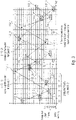
- FIG. 3 shows in detail 3 in a diagram a division of the frequency band into resources and a frequency and defined by two different channel access patterns time jump-based allocation of the resources of the frequency band.
- the ordinate describes the frequency channel indices and the abscissa describes the time slot indices.
- participants in the first communication system 102_1 can communicate wirelessly with one another based on the first channel access pattern 110_1, which specifies a frequency-hopping-based allocation of resources in the frequency band that can be used for the communication of the first communication system 102_1, while participants in the second communication system 102_2 can communicate with one another based on the second channel access pattern 110_2, which indicates a frequency hopping-based occupancy of resources of the frequency band that can be used for the communication of the second communication system 102_2, communicate wirelessly with one another, the first channel access pattern and the second channel access pattern being different (e.g. having an overlap of less than 20%, ideally having no overlap).
- the first channel access pattern and the second channel access pattern being different (e.g. having an overlap of less than 20%, ideally having no overlap).
- 3 shows an overview of all fundamentally available resources in frequency and time in the form of a grid (schematic representation of the frequency channels and time slots as well as exemplary channel access patterns), with an individual resource element in the first communication network 102_1 being determined by assigning a frequency channel index and a time slot index.
- the resources that can be occupied by the first communication network 102_1 are the resource elements identified by the reference symbol 112_1.
- the set of all resources that can be used within a communication network represents a channel access pattern 110_1.
- the channel access pattern of another communication network e.g.
- the second communication network 102_2) is in 3 entered by way of example (all resource elements identified by reference numbers 112_2, which are connected by arrows), which is not anchored in the same frequency and time grid as the first communication network 102_1 (resource elements are shifted in frequency and time from the basic grid of the first communication network 102_1).
- the design of the channel access pattern thus also means a specification of the actively usable resource reserve for this communication network (or communication system).
- Exemplary embodiments of base stations, end points and/or communication systems are described below that use channel access patterns for communication that meet at least one of the criteria a) to e) mentioned above. Furthermore, exemplary embodiments of the generation of such channel access patterns are described below.
- FIG. 4 shows a schematic block diagram of a communication system 102 with a base station 104 and a plurality of endpoints 106_1-106_4, according to an embodiment.
- the communication system 102 may include a base station and four endpoints 106_1-106_4.
- the present invention is not limited to such exemplary embodiments, rather the communication system can have one or more end points 106_1-106_n, where n is a natural number greater than or equal to one.
- the communication system may have 1, 10, 100, 1,000, 10,000, or even 100,000 endpoints.
- the communication system 102 works in an uncoordinated manner in relation to the other communication systems that use the same frequency band.
- the base station 104 can be configured to transmit a signal 120, the signal 120 having information about a channel access pattern 110, wherein the channel access pattern indicates a frequency and/or time jump-based occupancy (e.g. of resources) of the frequency band that can be used for the communication of the communication system 102 (e.g. a chronological sequence of frequency resources that can be used for the communication of the communication system (e.g. distributed over the frequency band), wherein the Information describes a state of a number sequence generator for generating a number sequence, the number sequence determining the channel access pattern.
- the channel access pattern indicates a frequency and/or time jump-based occupancy (e.g. of resources) of the frequency band that can be used for the communication of the communication system 102 (e.g. a chronological sequence of frequency resources that can be used for the communication of the communication system (e.g. distributed over the frequency band)
- the Information describes a state of a number sequence generator for generating a number sequence, the number sequence determining the channel access pattern.
- the state of the number sequence generator can be an internal state of the number sequence generator, it being possible for a number of the number sequence to be derived from the internal state of the number sequence generator.
- internal states of the number sequence generator that follow the internal state of the number sequence generator can also be determined, from which subsequent numbers in the number sequence can also be derived.
- At least one of the end points 106_1-106_4 can be configured to receive the signal 120 with the information about the channel access pattern 110, and to determine the channel access pattern 110 based on the information about the channel access pattern, the information being a state of a number sequence generator for describes generation of a sequence of numbers, the sequence of numbers determining the channel access pattern.
- the base station 104 and/or at least one of the endpoints 106_1-106_4 may be configured to pseudo-randomly determine the channel access pattern depending on the state of the sequence generator, such as using a pseudo-random mapping function.
- the base station 104 and/or at least one of the endpoints 106_1-106_4 can be designed to pseudo-randomly determine the channel access pattern depending on individual information of the communication system (eg intrinsic information of the communication system, such as a network-specific identifier).
- the channel access patterns are generated by the base station 104 and can be based on the signal with the information 120 about the channel access pattern from at least one (or all) of the in 4 Endpoints 106_1-106_4 shown are determined, for example by a respective controller (control device, control unit) 130, which is implemented in the base station 104 and/or in the endpoints 106_1-106_4.
- the channel access pattern is specified (exclusively) by the base station 104, while the end points 106_1-106_4 only “know” the channel access pattern, i.e. generate it using the same method as the base station 104.
- the following description assumes a radio transmission system (or a communication arrangement) with several independent, mutually uncoordinated communication networks, the participants of which are mutually within receiving range, so that transmission signals from participants in one network can potentially be considered as interference signals for participants in other networks.
- information data or signaling information
- base station which provides the non-coordinating participants in the network (hereinafter referred to as “terminals” or “end points”) with information about the channel access pattern used within the network can transmit.
- This information can, for example, be transmitted via regularly transmitted beacon signals, but it can also be transmitted at irregular intervals or, if necessary, dedicated to individual end devices or groups of end devices.
- the entire frequency band available for transmission is divided into a large number of individual frequency channels, which can each be accessed individually or in subsets (groups of frequency channels).
- channel access in the form of sending a signal can be done both by terminals and by the base station.
- channel access must be in an im Channel access patterns provided resource not necessarily done if, for example, no data or other information is pending for transmission.
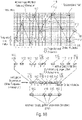
- figure 5 13 shows a schematic block diagram of a controller 130 for generating a channel access pattern, according to an embodiment of the present invention.
- the controller 130 can have a memory 132, a periodic number generator 134 for generating a periodic number sequence Z, a randomizing sequencer 136 and a frequency/time sequencer 138.
- the memory (e.g. a register) 132 can be designed to hold a network-specific identifier ID 140, e.g. a (individual) bit sequence, which does not change.
- the periodic number generator 134 can be designed to provide its state 142 or a number 142′ of the periodic sequence of numbers derived from its state.
- the randomizing allocator 136 can be designed to determine a pseudo-random number R 144 depending on the state 142 of the number sequence generator 134 or the number 142 ′ of the periodic number sequence derived therefrom and the network-specific identifier ID 140 .
- the frequency/time allocator 138 can be designed to determine frequency information f 146 and time information t 148 based on the pseudo-random number R 144 .
- the frequency information f 146 and the time information t 148 can describe or define a frequency channel and a time slot (or a frequency channel index and a time slot index) and thus a resource of the channel access pattern.
- the controller 130 can, for example - as described in 4 is indicated - implemented in the base station 104 and/or in the one or more endpoint(s) 106_1-106-4 to calculate the individual (or network individual) channel access pattern used by the communication system 102.
- figure 5 12 shows the basic structure for generating channel access patterns, according to an embodiment of the present invention.
- the channel access pattern is generated iteratively, ie the in figure 5 blocks shown are called once per generation of a single channel access information item. A channel access pattern with N channel accesses is thus generated by calling N times.
- number is used. This is generally discrete information that can be presented in different ways (e.g. in decimal form, as a binary sequence or similar).
- the network-specific identifier is a fixed number that is specified by an external entity (e.g. when configuring the network or the coordinating base station). Ideally, it differs from network to network. For example, it could be a unique, sufficiently long base station ID, unique network ID or a sufficiently long hash about it. This size is fixed and is the only one in the arrangement shown that does not vary from call to call.
- the periodic number generator 134 generates a sequence of numbers Z that is repeated periodically with the periodicity P. It has an internal state S n from which the next generated number and the next internal state S n+1 can be determined unambiguously.
- the decisive feature is that the entire periodic sequence for any time step can already be derived from a single internal state (which exists at any time step).
- a simple exemplary embodiment is, for example, a modulo P counter which periodically supplies the sequence of numbers 0,1,2...(P-1).
- a further exemplary embodiment is a deterministic random number generator (pseudo random number generator), for example implemented in the form of a feedback shift register (LFSR).
- LFSR feedback shift register
- a third embodiment is a finite field (Galois field) with P elements.
- the assignment is as random as possible, ie a mathematically correlated input sequence (consisting of ID, Z) generates an output sequence R that is as uncorrelated as possible.
- the sequence of the elements of the number R is of a pseudo-random nature. It should vary from network to network to minimize channel access pattern overlap.
- the time slots are indexed in chronologically ascending order, since "jumps back" in time are not permitted. Further information on the allocation of the time slots can be found in Section 3.
- the sequence of the 2-tuples (f,t) or (fi,ti) is based on the sequence of the elements of R and defines the channel access pattern.
- the arrangement shown generates a channel access pattern which depends both on a time-invariant, network-specific identifier and on a state-dependent (and thus time-changeable) periodic number generator (periodicity P).
- the network-specific identifier can be used to ensure that networks with different network-specific identifiers always generate different sequences of R, even if their number generator is in the same state. In this way it can be ensured that different networks do not generate identical channel access patterns and thus, in the worst case, end up in a "permanent collision" of the channel accesses.
- a terminal device To determine the channel access pattern used in the network, a terminal device requires both the network-specific identifier and the respective status of the periodic number generator.
- the end device receives the network-specific identifier when it first registers with the network. This is advantageously transmitted by means of beacon signals (beacon) sent out regularly by the base station and made accessible to all authorized terminals.
- the network-specific identifier can also be made known to the end device in the course of the initial configuration (with delivery), i.e. before the first commissioning in the network.
- the state of the periodic number generator can be communicated either in a regular beacon signal and/or in separate, dedicated state signaling resources.
- a number generator with periodicity P has P internal states, so that ⁇ log 2 ( P ) ⁇ bits must be transmitted to transmit the respective state.
- the amount of information (number of bits) transmitted per status signaling can thus be controlled by the selected periodicity of the number generator as required.
- the information transmitted for the status signaling can be transmitted in the form of a plurality of pieces of information, with the transmission being able to take place at different frequencies.
- the periodic number generator (Z) is a counter
- the more significant bits (most significant bits (MSBs)) of the counter could be separated from the less significant bits (least significant bits (LSBs)) are transmitted and also with a different frequency (e.g. less frequently).
- LSBs least significant bits
- a terminal which is aware of the state of the number generator at at least one point in time can determine the entire channel access pattern for any point in time/time slot in the future. It is thus possible for the terminal device to deactivate the transceiver unit, for example, in an energy-saving idle state and, when the transceiver unit is subsequently activated, to predict the section of the channel access pattern that is then valid from the last previously known state.
- the status information can therefore be sent by the base station at comparatively large time intervals.
- the method described here has the advantage that a comparatively large state space for the (pseudo-random) number R is spanned by the combination of a network-specific identifier and a periodic number generator. This prevents the channel access patterns of networks with different network-specific identifiers from being identical, which means that a systematic collision of the channel accesses of different networks that are not coordinated with one another can be minimized. This proves to be particularly advantageous with the Telegram Splitting Multiple Access (TSMA) method.
- TSMA Telegram Splitting Multiple Access
- a periodic number generator 134 is required. This is replaced as follows in the following exemplary embodiment.
- beacon transmission can be provided with a counter which corresponds to a beacon sequence index.
- This beacon sequence index is referred to herein as the "beacon index”.
- time slots in a time slot-based system are provided with a time slot index counter (increasing in the time direction) (see also 3 ). This is referred to herein as the "timeslot index".
- the beacon index is reset to zero at certain intervals specified in the system, so that it has a periodicity having. The same applies to the time slot index (which, for example, starts again at zero after a beacon transmission).
- 6 13 shows a schematic block diagram of a controller 130 for generating a channel access pattern, according to an embodiment of the present invention.
- the controller 130 may include a memory 132, a first buffer 135_1, a second buffer 135_2, a randomizing allocator 136, and a frequency/time allocator 138.
- the memory (e.g. a register) 132 can be designed to hold a network-specific identifier ID 140, e.g. a (individual) bit sequence, which does not change.
- the first buffer (e.g. a register) 135_1 can be designed to hold a periodic beacon index Z1 143_1.
- the second buffer (e.g. a register) 135_2 can be designed to hold a periodic time slot index Z2 143_2.
- the randomizing allocator 136 can be designed to determine a pseudo-random number R 144 as a function of the periodic beacon index Z1 143_1 , the periodic time slot index Z2 143_2 and the network-specific identifier ID 140 .
- the frequency/time allocator 138 can be designed to determine frequency information f 146 and time information t 148 based on the pseudo-random number R 144 .
- the frequency information f 146 and the time information t 148 can describe or define a frequency channel and a time slot (or a frequency channel index and a time slot index) and thus a resource of the channel access pattern.
- 6 shows a modified basic structure for generating channel access patterns with beacon index and timeslot index.
- an exemplary embodiment is shown in which, compared to that in figure 5
- the periodic number generator (output Z) 134 was replaced by the two blocks "periodic beacon index” (output Z1) 135_1 and “periodic time slot index” (output Z2) 135_2. All other blocks are functionally unchanged (the randomizing mapper now has three inputs).
- the frequency range (or frequency band) is divided into discrete frequency channels and that transmission is based on the TSMA method.
- Mobile radio channels usually have a signal attenuation that varies over the frequency. If, according to the TSMA method, a data packet is transmitted in the form of several partial data packets and the underlying mobile radio channel is not known in the transmitter, the error rate of the transmission can be reduced on average or even minimized by the individual partial data packets being transmitted over the entire frequency range as far as possible distributed (use of frequency diversity).
- a suitable method can be used ensure that there is a minimum distance between two consecutive frequency channels of the channel access pattern.
- the frequency/timing time allocator 138 (see figure 5 or 6 ) therefore be designed to determine frequency information f and time information t based on the pseudo-random number R, the frequency information f indicating a distance between two consecutive frequency channels.
- the frequency/time allocator 138 in figure 5 or 6 which independently defines absolute frequency channels from access to access on the basis of the pseudo-random number R, can alternatively also determine distances between two consecutive frequency channels.
- the frequency/time allocator 138 (see figure 5 or 6 ) be designed to determine frequency information and time information based on the pseudo-random number R, the frequency information indicating a distance ⁇ fi n between two consecutive frequency channels.
- controller 130 can have a mapper 150, which can be designed to map the distance ⁇ fi n between two consecutive frequency channels to a frequency channel index fi, for example by a combiner (e.g. adder) 152 and a delay element 154.
- a mapper 150 can be designed to map the distance ⁇ fi n between two consecutive frequency channels to a frequency channel index fi, for example by a combiner (e.g. adder) 152 and a delay element 154.
- 7 shows the generation of frequency hops with a minimum and/or maximum hop width.
- the frequency / time allocator 138 of figure 5 or 6 is now replaced by a frequency difference/point in time allocator 138, which no longer supplies absolute frequency channel indices at its immediate output, but rather frequency channel index differences.
- ⁇ fi max ⁇ fi ⁇ fi min for ⁇ fi>0
- ⁇ fi max ⁇ (- ⁇ fi) ⁇ fi min for ⁇ fi ⁇ 0.
- FIG. 12 shows in a diagram a frequency-based and time jump-based occupancy of the resources 112 of the frequency band defined by a channel access pattern 110 and a projection of the channel access pattern 110 onto a time axis, according to an embodiment of the present invention.
- the ordinate describes the frequency channel indices and the abscissa describes the time slot indices.
- 9 shows in the upper part an example of a channel access pattern 110 in the dimensions of frequency and time (resource elements 112) and in the lower part its projection onto the time dimension. It can be seen that not every time slot is part of the channel access pattern 110.
- the time dimension in the form of the time slot index
- the time dimension is therefore also available for the generation of a pseudo-random channel access pattern 110 .
- the activity rate thus determines the (temporal) density of the resources 112 offered in the channel access pattern 110.
- the time slots selected for a given activity rate for channel access can be pseudo-randomly selected from a suitable part of the pseudo-random number R (see figure 5 or 6 ) are determined.
- an integer r n can be derived from the associated pseudo-random number R n , which can assume values between r min and r max , ie r min ⁇ r n ⁇ r max .
- R n pseudo-random number
- FIG. 10 shows in detail 10 in a diagram, resource elements 112 of a channel access pattern 110 projected onto a time axis, resulting in unused time slots, according to an embodiment.
- 10 12 shows an example sequence of used and unused time slots, according to an embodiment.
- the method presented in the above exemplary embodiment has the advantage that minimum and maximum distances between the time slots active in the channel access pattern 110 can be specified.
- the specification of minimum distances can be particularly advantageous for battery-powered devices in which pauses in transmission of a certain Minimum length between two consecutive transmissions (recovery phase) increase battery life.
- groups of consecutive time slots are specified periodically, within each of which an active time slot of the channel access pattern is placed. This is for an activity rate of 1/4 (25%) in 11 shown as an example.
- 11 12 shows an example sequence of used and unused time slots, according to an embodiment.
- the time slots can be grouped into clusters 114 (in the example of 11 of length 4) are grouped. Exactly one time slot of the channel access pattern 110 is placed in each cluster 114 .
- the position of the time slots included in the channel access pattern 110 within the cluster 114 can be determined by a displacement v n which is derived from the pseudo-random number R n and which can assume integer values between 0 and (cluster length-1).
- areas that cannot be used can be introduced between the clusters 114 . These can consist of one or more time slots, as shown in 12 is illustrated.
- 12 shows an exemplary sequence of used and unused time slots with non-allocable time slots, according to an embodiment.
- the permissible range of the shift variable v n is reduced to the value range from 0 to (cluster length-1-length of the non-assignable area) due to the time slots that cannot be used.
- the clusters 114 may need to be of different lengths to achieve the desired activity rate.
- the value range of v n varies according to the respective cluster length. For example, to set an activity rate of 40%, clusters of length two and length three can alternate.
- Data packets that are to reach the recipient as quickly as possible require channel accesses that follow each other as closely as possible during transmission, i.e. a comparatively high activity rate in the channel access pattern.
- the activity rate ie the frequency of channel access
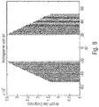
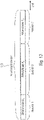
- a channel access pattern can be designed in such a way that it has areas with different activity rates. This is in 13 shown as an example.
- end devices can then, for example, transmit in the area that is suitable for them.
- FIG. 13 shows in detail 13 a temporal division of a channel access pattern 110 into areas of different activity rates A 1 , A 2 and A 3 , according to an embodiment.
- 13 shows an example of a channel access pattern with three areas of different activity rates within the channel access pattern 110.
- Networks (or communication systems) 102 may have different load situations at different times.
- the actively usable resource reserve for this network can be defined via the design of the channel access pattern 110 (i.e. its activity rate or average temporal density).
- a battery-operated base station e.g. in a PAN network, possibly in repeater mode
- PAN network possibly in repeater mode
- a battery-operated base station which operates the receiver during all active resources of the channel access pattern and thus uses energy.
- the mean activity rate ie the temporal density of the resources offered by the channel access pattern 110, to the prevailing load conditions. If the activity rate of the channel access pattern 110 is changed, this is signaled accordingly to the participants in the network, for which e.g. the beacon signal (or also dedicated signaling resources) comes into question.
- a terminal device 106 If a terminal device 106 is in a longer idle state (power-saving mode), it may happen that it does not receive the signaling information sent out by the base station 104 during the idle state about a possibly changed channel access pattern. In such a scenario, it may make sense for a channel access pattern 110 to provide a minimum pool of (basic) resources that are available at all times and without special signaling, and an additional pool of resources that can be added depending on the load and is subject to appropriate signaling .
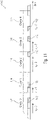
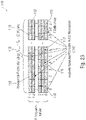
- Resources that are additionally added to the channel access pattern in the above sense can, for example, be arranged chronologically after the basic resources or also be arranged interleaved with them in the time/frequency grid, as is shown in 14 is shown.
- FIG. 14 shows in detail 14 in a diagram a defined by a channel access pattern 110 frequency and time jump-based occupancy of the resources 112 of the frequency band, where the channel access pattern 110 additionally has resources 112* that can be activated on demand, according to an embodiment of the present invention.
- the ordinate describes the frequency channel indices and the abscissa describes the time slot indices.
- 14 shows an example of entangled basic and additional resources.
- users may be able to decide for themselves which frequency ranges they use within the frequency band without regulatory restrictions. This can mean that certain areas of the available frequency band are occupied more by external users than others and are therefore exposed to greater interference.
- a base station 104 detects such a medium or long-term asymmetric utilization of the frequency band (e.g. through frequency-channel signal-to-interference power estimates based on received signals), the above-average heavily occupied area of the frequency band can be avoided for use by its own network, by not including the associated frequency channels in the channel access pattern. This is in the frequency/timing allocator (see figure 5 or 6 ) must be taken into account and is signaled to all network participants in a suitable manner.
- the group of frequency channels excluded can be described, for example, by a corresponding starting and ending frequency channel index or by a starting frequency channel index and a following channel number.
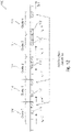
- FIG. 15 shows in a diagram a frequency-based and time jump-based occupancy of the resources 112 of the frequency band defined by a channel access pattern 110, wherein a frequency range 115 of the frequency band that is regularly subject to more interference is not occupied by the channel access pattern 110, according to an embodiment of the present invention.
- the ordinate describes the frequency channel indices and the abscissa describes the time slot indices.
- 15 shows an example for excluding strongly disturbed frequency channels from the channel access pattern.
- a base station 104 may be able to receive on a number of frequency channels at the same time (frequency channel bundling).
- frequency channel bundling it is advantageous, especially in the case of systems with higher loads, to increase the number of resource elements offered within the network in the frequency dimension accordingly and to include several frequency channels within a time slot in the channel access pattern, as is shown in 16 is shown.
- a channel access pattern 110 defines a frequency-based and time-jump-based occupancy of the resources 112 of the frequency band, with resources 112 being bundled in the frequency domain, according to an embodiment.
- the ordinate describes the frequency channel indices and the abscissa describes the time slot indices.
- 16 shows an exemplary representation of the channel access pattern 110 when bundling three adjacent frequency channels to form resource clusters.
- the bundling of three frequency channels is shown as an example.
- Each group of resource elements of a time slot can be referred to as a "resource cluster”.
- the channel access pattern 110 can be supplemented by information about the number of frequency channels that constitute a resource cluster.
- the frequency channels grouped into resource clusters do not necessarily have to be directly adjacent.
- the following shows how one or more participants in a communication system 102 using a relative channel access pattern to a Selection of the resources released by the network-specific channel access pattern 110 for the communication system 102 can access.
- FIG. 17 shows a schematic block diagram of a communication system 102 with a base station 104 and two endpoints 106_1-106_2, according to an embodiment of the present invention.
- the communication system 102 shown has, for example, a base station 104 and two endpoints 106_1-106_2.
- the present invention is not limited to such exemplary embodiments, rather the communication system 102 can have one or more endpoints 106_1-106_n, where n is a natural number greater than or equal to one.
- the communication system may have 1, 10, 100, 1,000, 10,000, or even 100,000 endpoints.
- the communication system 102 works in an uncoordinated manner in relation to the other communication systems that use the same frequency band.
- the base station 104 is designed to transmit a signal 120, the signal 120 having information about a network-specific channel access pattern 110, the network-specific channel access pattern 110 having a frequency and /or indicates time jump-based occupancy of resources of the frequency band, while the end points 106_1-106_2 are designed to receive the signal 120 and to determine the network-specific channel access pattern 110 based on the information about the network-specific channel access pattern (see e.g figure 5 and 6 ).
- the participants e.g. base station 104 and endpoint 106_1
- the participants can use a relative channel access pattern which indicates which of the network-specific channel access patterns 110 for the communication of the Communication system 102 released or usable resources are actually to be used for the transmission of data.
- the base station 104 may be configured to transmit (e.g., transmit to and/or receive from endpoint 106_1) data 160 (e.g., a signal including data 160) using a relative channel access pattern. wherein the relative channel access pattern indicates an occupancy of resources to be used for the transmission from the usable frequency and/or time jump-based occupancy of resources of the network-specific channel access pattern 110 .
- the endpoint 106_1 may be configured to transmit (e.g., receive from and/or transmit to the base station 104) data 160 (e.g., a signal comprising the data 160) using the relative channel access pattern, where the relative Channel access pattern indicates an allocation of resources to be used for the transmission from the usable frequency and/or time jump-based allocation of resources of the network-specific channel access pattern.
- data 160 e.g., a signal comprising the data 160
- the relative Channel access pattern indicates an allocation of resources to be used for the transmission from the usable frequency and/or time jump-based allocation of resources of the network-specific channel access pattern.
- a different relative channel access pattern can be used for mutual communication between other participants (e.g. base station 104 and endpoint 106_2) of the communication system 102, which indicates which of the resources released or usable by the network-specific channel access pattern 110 for the communication of the communication system 102 are actually available for the transmission of the data where the relative channel access pattern (e.g. from endpoint 106_1) and the other relative channel access pattern (e.g. from endpoint 106_2) are different.
- the relative channel access pattern e.g. from endpoint 106_1
- the other relative channel access pattern e.g. from endpoint 106_2
- the base station 104 may be further configured to transmit data 162 (e.g. a signal with the data 162) using a different relative channel access pattern (e.g. to send to the other endpoint 106_2 and/or from the other endpoint 106_2 to receive), wherein the other relative channel access pattern indicates an allocation of resources to be used for the transmission from the usable frequency and/or time jump-based allocation of resources of the network-specific channel access pattern, the relative channel access pattern and the other relative channel access pattern being different.
- data 162 e.g. a signal with the data 162
- a different relative channel access pattern e.g. to send to the other endpoint 106_2 and/or from the other endpoint 106_2 to receive
- the other relative channel access pattern indicates an allocation of resources to be used for the transmission from the usable frequency and/or time jump-based allocation of resources of the network-specific channel access pattern, the relative channel access pattern and the other relative channel access pattern being different.
- the other endpoint 106_2 can be configured to transmit data 162 (e.g. a signal with the data 162) using the other relative channel access pattern (e.g. to receive from the base station 104 and/or to transmit to the base station 104), wherein the other relative channel access pattern indicates an occupancy of resources to be used for the transmission from the usable frequency and/or time jump-based occupancy of resources of the network-specific channel access pattern, the relative channel access pattern and the other relative channel access pattern being different.
- data 162 e.g. a signal with the data 162
- the other relative channel access pattern indicates an occupancy of resources to be used for the transmission from the usable frequency and/or time jump-based occupancy of resources of the network-specific channel access pattern, the relative channel access pattern and the other relative channel access pattern being different.
- the relative channel access patterns can be determined by the participants (e.g. the base station 104 and at least one of the endpoints 106_1-106_2), for example by the controller 130 implemented in the participants.
- the following exemplary embodiments refer to the exemplary embodiments described in Section A, which, when there are several uncoordinated radio networks (e.g. LPWAN, PAN) in mutual reception range, design access to a shared frequency band in such a way that the cross-network, mutual interference of the participants or their adverse effects on transmission security are reduced or even minimized.
- LPWAN low-power wide area network
- PAN personal area network
- TSMA Telegram Splitting Multiple Access
- base station referred to as “PAN coordinator” in the context of the IEEE standard [2]
- PAN coordinator provides the non-coordinating participants of the network
- endpoints can convey information about the channel access pattern used within the network.
- the channel access patterns described above define a set of radio resources (resource elements) that are fundamentally available for transmission within a network for a specific period of time. you define thus the range of resources specified by the base station (valid for the period under consideration) to which the end devices can access.
- competition-free access a terminal is assigned uniquely specified radio resources for exclusive use by the coordinating entity (base station).
- the coordinating entity base station
- the terminal has a range of radio resources available, from which the terminal uses its own initiative, i.e. without individual resource allocation, if required. It is characteristic here that other end devices can also access the same offer, so that conflicts can arise when accessing the shared radio resources. The aim is to reduce or even avoid these conflicts as far as possible.
- Exemplary embodiments thus deal with techniques that make the distribution of the existing resources (which have been defined by the base station) as effective as possible, so that the interference between the participants within the network is reduced or even minimized.
- Exemplary embodiments provide that there is a stock of relative channel access patterns known to both the base station and the terminals of the network, from which the terminal uses one, for example, for each transmission.
- the selection of a relative channel access pattern from the available pool can be based on various criteria and is described in more detail below.
- the actively used relative channel access pattern of a network participant thus consists of a subset of the network-specific channel access pattern.
- the use of the exemplary embodiments described here is particularly advantageous for data transmission using the TSMA method, in which a data packet is transmitted divided into a number of partial data packets.
- the following representation assumes that the frequency band is divided into a number of discrete frequency channels and that the accesses within a network are also discretized in terms of time in the form of time slots .
- FIG. 18 shows in a diagram a frequency- and time-jump-based usable occupancy of resources 112 of the frequency band indicated by a network-specific channel access pattern 110, an occupancy of resources 118 to be used for transmission indicated by a relative channel access pattern 116 from the usable occupancy of resources 112 of the network-specific channel access pattern 110, as well as projections of the channel access patterns 110, 116 on time axes before and after removal of unused resources (eg time slots), according to an embodiment.
- the ordinate describes the frequency channel indices and the abscissa describes the time slot indices.
- the network-specific channel access pattern 110 defines the distribution of the resources 112 of the frequency band (e.g. each defined by time slot and frequency channel, or time slot index and frequency channel index), which are used by the communication system 102 and thus by the participants (base station 104 and end points 106_1-106_2) of communication system 102 can be used for mutual communication, while relative channel access pattern 116 indicates those resources 118 from usable resources 112 that are used by a subset of the participants (e.g., a limited group of participants, e.g., by two participants, such as base station 104 and Endpoint 106_1) of the communication system 102 are actually used for mutual communication.
- a subset of the participants e.g., a limited group of participants, e.g., by two participants, such as base station 104 and Endpoint 106_1 of the communication system 102 are actually used for mutual communication.
- 18 shows a schematic exemplary representation of the network-specific and relative channel access pattern (hierarchical structure of channel access). while showing 18 in the upper part, for example, the distribution of the radio resources in a discrete time/frequency grid into a large number of resource elements.
- a resource element is described by a frequency channel index and a time slot index.
- a network-specific channel access pattern 110 is illustrated, which is highlighted by resource elements 112 which are symbolically connected to one another by arrows.
- This network-specific channel access pattern 110 represents the supply of resource elements 122 that a network (or communication system) 102 makes available. In this example, a signal transmission is only possible on one frequency channel in a time slot.
- the two-dimensional representation is projected onto the time axis and all the time slots that are not occupied in the network-specific channel access pattern 110 are removed, the result is the "available resources" 112 according to the above representation.
- the time indexing can advantageously be done here by a relative time slot index, which is relative to the network-specific channel access pattern .
- a relative channel access pattern 116 is shown as an example, which defines a subset of the available resources (possibly also all of them). That in selected example effectively resulting channel access pattern (ie the hierarchical combination of network-specific and relative channel access pattern) is in all areas of 18 denoted by resource elements 118.
- the relative channel access pattern with its relative time slot index can be calculated back to the original discrete time grid using the mean activity rate A defined in Section A. This average activity rate is defined as the average ratio of time slots used for channel access to the total maximum available time slots. If each time slot is used, the activity rate A is therefore 1 (100%).
- a base station 102 may be able to receive on a number of frequency channels at the same time (frequency channel bundling).
- frequency channel bundling it is advantageous, particularly in the case of systems with higher loads, to correspondingly increase the number of resource elements offered within the network in the frequency dimension and to include a number of frequency channels within a time slot in the network-specific channel access pattern 110 . this is in 19 shown.
- FIG. 19 shows in detail 19 in a diagram, a frequency- and time-jump-based usable allocation of resources 112 of the frequency band bundled in the frequency domain, indicated by a network-specific channel access pattern 110, an allocation of resources 118 to be used for the transmission, indicated by a relative channel access pattern 116, from the usable allocation of resources 112 of the network-specific Channel access pattern 110, and projections of the channel access pattern 110, 116 on time axes before and after removal of unused resources (e.g. time slots).
- the ordinate describes the frequency channel indices and the abscissa describes the time slot indices.
- the network-specific channel access pattern 110 in the frequency direction is a bundling of resources 112, ie a plurality of adjacent resources 112 (e.g. frequency channels or frequency channel indices) of the frequency band, with the relative channel access pattern 116 in the frequency direction at most one Subset (e.g. at most one resource, i.e. one or no resource) of the plurality of neighboring resources 112 of the network-specific channel access pattern 110 indicates.
- 19 shows a schematic exemplary representation of the network-specific channel access pattern 110 and the relative channel access pattern 116 with gapless frequency channel bundling.
- the occupancy of the (in the example: three) frequency channels is also available as a degree of freedom.
- FIG. 20 shows in a diagram a frequency- and time-jump-based usable allocation of resources 112 of the frequency band that are spaced apart from one another in the frequency domain, indicated by a network-specific channel access pattern 110, an allocation of resources 118 to be used for transmission, indicated by a relative channel access pattern 116, from the usable allocation of resources 112 of the network-specific channel access pattern 110, an allocation of resources 119 to be used for the transmission, specified by another relative channel access pattern 117, from the usable allocation of resources 112 of the network-specific channel access pattern 110, and projections of the channel access patterns 110, 116, 117 on time axes before and after removal of unused ones Time slots or frequency channels, according to an embodiment.
- the ordinate describes the frequency channel indices and the abscissa describes the time slot indices.
- the network-specific channel access pattern 110 in the frequency direction is a bundling of resources 112, ie a plurality of spaced-apart resources 112 (e.g. frequency channels or frequency channel indices) of the frequency band, with the relative channel access pattern 116 in the frequency direction at most indicates a subset (e.g. at most one resource, i.e. one or no resource) of the plurality of spaced-apart resources 112 of the network-specific channel access pattern 110, and wherein that other relative channel access pattern 117 in the frequency direction indicates at most a subset (e.g. at most one resource, ie one or no resource) of the plurality of spaced-apart resources 112 of the network-specific channel access pattern 110, the relative channel access pattern 116 and the other relative channel access pattern 117 being different.
- resources 112 e.g. frequency channels or frequency channel indices
- 20 shows a schematic exemplary representation of the network-specific channel access pattern 110 and the relative channel access pattern 116 in the case of gapped frequency channel bundling.
- this frequency channel bundling is that, as shown in the in 20 additionally shown relative channel access pattern 117 of a second participant (e.g. user) significantly less adjacent channel interference (the channel separation of two directly adjacent channels is always problematic due to the limited filter effect, especially when one channel is received with a significantly stronger reception power than the adjacent channel) as in 19 occurs.
- a second participant e.g. user
- the advantage of in the 19 and 20 The bundling described above consists in giving access to the radio resources to more terminals within the network and within a given period of time (higher load). Alternatively, with a given load, the probability of channel access collisions can be reduced by channel bundling, since a given access volume is distributed over more potential resource elements (reduced mutual interference between the participants within the network).
- the advantage of frequency channel bundling over the use of more time slots is also greater energy efficiency, since the receiver switches on the receiver for fewer time slots given the same range of resource elements.
- a terminal has the ability to transmit on several frequency channels simultaneously, this can be provided for in the relative channel access pattern. This is illustrated in the figure below, which is limited only to the relative channel access pattern (corresponding to the lower parts of 19 and 20 ).
- 21 shows in a diagram a projection of a network-specific channel access pattern 110 and a relative channel access pattern 116 onto the time axis after the removal of unused frequency channels and time slots, the relative channel access pattern 116 in the frequency direction for at least part of the time jumps several of the resources 112 available in the frequency direction are occupied.
- the ordinate describes the relative frequency channel indices and the abscissa describes the relative time slot indices.
- 21 shows in a diagram a relative channel access pattern 116 in the case of frequency channel bundling with simultaneous transmission (eg transmission) on a plurality of frequency channels.
- the signal is generated on each frequency channel with an identical symbol rate.
- this area referred to below as a “resource cluster”
- Different symbol rates and/or a different number of symbols can be assigned to these sub-resources, as shown in 22 is illustrated.
- FIG. 22 shows in a diagram a frequency- and time-jump-based usable occupancy specified by a network-specific channel access pattern 110 of resources 112 of the frequency band bundled in the frequency domain to form blocks (or clusters) 113, with different parts 111_1-111_4 of the block 113 of related resources 112 having different symbol rates and/or or are assigned different numbers of symbols, according to one embodiment.
- the ordinate describes the frequency channel indices and the abscissa describes the time slot indices.
- 22 shows the formation of resource clusters 113 with sub-resources 111_1-111_4 with different symbol rates and number of symbols per time slot (example).
- each resource cluster 113 is divided into four independent sub-resources “A” (111_1), “B” (111_2), “C” (111_3), “D” (111_4), in which different multiples of the symbol rate f s and the number of symbols N s are used.
- A 111_1
- B 111_2
- C 111_3
- D 111_4
- different multiples of the symbol rate f s and the number of symbols N s are used.
- two consecutive accesses can take place in a time slot, for example due to the shortened symbol duration by two different participants. this is in 22 the case for the chronologically consecutive sub-resources “B” (111_2) and “C” (111_3).
- the advantage of this procedure is that within the network-specific channel access pattern 110 resources can be occupied with different symbol rates and thus transmission bandwidths as required.
- resource clusters 113 formed by frequency channel bundling can be divided into individual sub-resources in a variety of ways.
- the symbol rates used in this case do not necessarily (as in the selected example) have to be integer multiples of a basic symbol rate. The same applies to the number of symbols in the sub-resources.
- Data packets that are to reach the recipient as quickly as possible require channel accesses that follow each other as closely as possible during transmission, i.e. a comparatively high activity rate A in the network-specific channel access pattern, as described in section A.
- transmission security e.g. high robustness against external interference
- distribution of the transmission over a longer period of time can be advantageous, i.e. a comparatively low activity rate A in the network-specific channel access pattern can be beneficial.
- a temporally equalized energy consumption from the battery time-stretched transmission activity
- 23 12 is a diagram showing a projection of a network-specific channel access pattern 110 and a relative channel access pattern 116 with D resources 112 onto the time axis after removing unused resources (frequency channels and time slots), according to an embodiment.
- the ordinate describes the relative frequency channel indices and the abscissa describes the relative time slot indices.
- the number of available resource elements is to be determined based on the total frame duration T frame and the network-specific activity rate A from section A and the time duration T RE for a resource element.
- T Frame T RE • (Z / A) it depends on the application.
- T Frame should not be greater than 500 ms.
- the duration of a resource frame can easily assume values of 5 to 10 seconds.
- the network-specific activity rate A from section A is also influenced by the use case.
- duration T RE of a partial data packet or resource element still applies.
- a symbol rate f S of, for example, around 2500 sym/s and a number of 30 to 80 symbols per partial data packet values of 12 to 32 ms result for T RE .
- the number Z of resources available in the time direction can be determined from the application-specific specifications for T Frame , T RE and A. Together with the F specified frequency channels, the total resources available per resource frame then result. As in the in 24 shown in the table shown, these values can differ significantly depending on the application.
- FIG. 24 shows in detail 24 in a table a resource calculation for various exemplary use cases.
- the second design step applies the length D of each channel access pattern and the available F ⁇ Z resource elements that To determine the number M of different channel access patterns.
- M Max Z ! ⁇ f D / Z ⁇ D ! ⁇ D ! different channel access patterns of length D that differ in at least one resource element.
- M max would again increase massively.
- the number D of sub-packets should be selected as large as possible, since then the robustness to interference from other participants is greatest, regardless of whether they come from your own network or from other networks.
- a data packet is usually broken down into 10 to 30 partial data packets. If a transmission time corresponding to this number of partial data packets is not available, as is the case with some latency-critical applications, the value of D can also be smaller.
- M 1024
- 25 shows in a diagram simulation results of the packet error rate for different channel access pattern lengths M as a function of the number of simultaneously active terminals with 360 resource elements.
- the ordinate describes the packet error rate PER and the abscissa describes the number of N terminals (eg end points) active simultaneously in the resource frame.
- N 2 terminals
- 26 shows in a diagram simulation results of the packet error rate for different channel access pattern lengths M as a function of the number of simultaneously active terminals with 60 resource elements.
- the ordinate describes the packet error rate PER and the abscissa describes the number of N terminals (eg end points) active simultaneously in the resource frame.
- M max 10 14
- M 1024 proves to be sensible. If the value of M max falls below the threshold of 10 14 , M can be reduced accordingly, with simulations having to be used to check to what extent the PER performance still satisfies the requirements. for very large values of M max , M can certainly assume values that are even greater than 1024. This can be determined by appropriate simulations.
- the number M of different channel access patterns and their length D was determined.
- the individual channel access patterns are determined by means of a random number generator, as a result of which there is as little connection or similarity as possible between the M individual patterns.
- this usually means a very large detection effort.
- an attempt is made in the third design step to give the channel access patterns structural properties such as clustering or repeating patterns in order to significantly reduce the computational complexity on the receiver side.
- the PER performance, such as in the 25 and 26 shown should not deteriorate as much as possible.
- One possibility is to subdivide the resource frame into clusters 114 of the same length L, as shown in 27 is shown.
- FIG. 2 shows a flow diagram of a method 200 for operating an endpoint of a communication system, wherein the communication system communicates wirelessly in a frequency band which is used by a plurality of communication systems for communication.
- the method 200 includes a step of receiving a signal, the signal having information about a network-specific channel access pattern, the network-specific channel access pattern indicating a usable frequency and/or time jump-based occupancy of resources of the frequency band for the communication of the communication system.
- the method 200 further includes a step 204 of transmitting data using a relative channel access pattern, the relative channel access pattern specifying an allocation of resources to be used for the transmission from the usable frequency and/or time jump-based allocation of resources of the network-specific channel access pattern.
- the method 210 includes a step 212 of sending a signal, the signal having information about a network-specific channel access pattern, the network-specific channel access pattern indicating a usable frequency and/or time jump-based occupancy of resources of the frequency band for the communication of the communication system.
- the method 210 further includes a step 214 of transmitting data using a relative channel access pattern, the relative channel access pattern specifying an allocation of resources to be used for the transmission from the usable frequency and/or time jump-based allocation of resources of the network-specific channel access pattern.
- the method 220 includes a step 222 of determining a network-specific channel access pattern, the network-specific channel access pattern indicating a usable for the communication of the communication system frequency and / or time jump-based occupancy of resources of the frequency band. Furthermore, the method 220 includes a step 224 of determining a relative channel access pattern, wherein the relative channel access pattern indicates an allocation of resources to be used for a transmission of data of the subscriber from the usable frequency and/or time jump-based allocation of resources of the network-specific channel access pattern.
- Exemplary embodiments are used in systems for radio transmission of data from terminals to a base station or from one or more base stations to terminals.
- a system can be a Personal Area Network (PAN) or a Low Power Wide Area Network (LPWAN), where the end devices can be battery-powered sensors (sensor nodes), for example .
- PAN Personal Area Network
- LPWAN Low Power Wide Area Network
- sensors sensors
- Exemplary embodiments are aimed at applications in which a message (data packet) is transmitted in a radio network in several partial data packets (so-called telegram splitting method, English Telegram Splitting [1]) and in which several mutually uncoordinated radio networks access common radio resources (e.g. common frequency band). .
- the exemplary embodiments described here can be used to transmit data based on the telegram splitting method between the users of the communication system.
- data such as a telegram or data packet
- data packet is divided into a plurality of sub-data packets (or sub-data packets, or sub-packets) and the sub-data packets are split using a time and/or frequency hopping pattern in time and/or or distributed in frequency from one participant to another participant (e.g. from the base station to the endpoint, or from the endpoint to the base station) of the communication system, with the participant receiving the sub-data packets reassembling (or combining) them to to receive the data package.
- Each of the sub data packets contains only part of the data package.
- the data packet can also be channel-coded, so that not all of the sub-data packets, but rather only some of the sub-data packets, are required for error-free decoding of the data packet.
- the sub-data packets can be distributed in a subset (e.g. a selection) of the available resources of the network-specific channel access pattern.
- the sub-packets can be transmitted based on the relative channel access pattern, i.e. in the resources of the relative channel access pattern. For example, one sub-data packet can be transmitted per resource.
- aspects have been described in the context of a device, it is understood that these aspects also represent a description of the corresponding method, so that a block or a component of a device is also to be understood as a corresponding method step or as a feature of a method step. Similarly, aspects described in connection with or as a method step also constitute a description of a corresponding block or detail or feature of a corresponding device.
- Some or all of the method steps may be performed by hardware apparatus (or using a hardware apparatus), such as a microprocessor, a programmable computer, or an electronic circuit. In some embodiments, some or more of the essential process steps can be performed by such an apparatus.
- embodiments of the invention may be implemented in hardware or in software. Implementation can be performed using a digital storage medium such as a floppy disk, DVD, Blu-ray Disc, CD, ROM, PROM, EPROM, EEPROM or FLASH memory, hard disk or other magnetic or optical memory, on which electronically readable control signals are stored, which can interact or interact with a programmable computer system in such a way that the respective method is carried out. Therefore, the digital storage medium can be computer-readable.
- a digital storage medium such as a floppy disk, DVD, Blu-ray Disc, CD, ROM, PROM, EPROM, EEPROM or FLASH memory, hard disk or other magnetic or optical memory, on which electronically readable control signals are stored, which can interact or interact with a programmable computer system in such a way that the respective method is carried out. Therefore, the digital storage medium can be computer-readable.
- Some embodiments according to the invention thus include a data carrier that has electronically readable control signals that are capable of a programmable Computer system to interact in such a way that one of the methods described herein is performed.
- embodiments of the present invention can be implemented as a computer program product with a program code, wherein the program code is effective to perform one of the methods when the computer program product runs on a computer.
- the program code can also be stored on a machine-readable medium, for example.
- exemplary embodiments include the computer program for performing one of the methods described herein, the computer program being stored on a machine-readable carrier.
- an exemplary embodiment of the method according to the invention is therefore a computer program that has a program code for performing one of the methods described herein when the computer program runs on a computer.
- a further exemplary embodiment of the method according to the invention is therefore a data carrier (or a digital storage medium or a computer-readable medium) on which the computer program for carrying out one of the methods described herein is recorded.
- the data carrier, digital storage medium, or computer-readable medium is typically tangible and/or non-transitory.
- a further exemplary embodiment of the method according to the invention is therefore a data stream or a sequence of signals which represents the computer program for carrying out one of the methods described herein.
- the data stream or sequence of signals may be configured to be transferred over a data communications link, such as the Internet.
- Another embodiment includes a processing device, such as a computer or programmable logic device, configured or adapted to perform any of the methods described herein.
- a processing device such as a computer or programmable logic device, configured or adapted to perform any of the methods described herein.
- Another embodiment includes a computer on which the computer program for performing one of the methods described herein is installed.
- a further exemplary embodiment according to the invention comprises a device or a system which is designed to transmit a computer program for carrying out at least one of the methods described herein to a recipient.
- the transmission can take place electronically or optically, for example.
- the recipient may be a computer, mobile device, storage device, or similar device.
- the device or the system can, for example, comprise a file server for transmission of the computer program to the recipient.
- a programmable logic device e.g., a field programmable gate array, an FPGA
- a field programmable gate array may cooperate with a microprocessor to perform any of the methods described herein.
- the methods are performed on the part of any hardware device. This can be hardware that can be used universally, such as a computer processor (CPU), or hardware that is specific to the method, such as an ASIC.
- the devices described herein may be implemented, for example, using hardware apparatus, or using a computer, or using a combination of hardware apparatus and a computer.
- the devices described herein, or any components of the devices described herein may be implemented at least partially in hardware and/or in software (computer program).
- the methods described herein may be implemented, for example, using hardware apparatus, or using a computer, or using a combination of hardware apparatus and a computer.
Description
Ausführungsbeispiele der vorliegenden Erfindung beziehen sich auf einen Controller für einen Teilnehmer eines Kommunikationssystems, auf eine Basisstation eines Kommunikationssystems, auf einen Endpunkt des Kommunikationssystems sowie auf das Kommunikationssystem, wobei das Kommunikationssystem in einem Frequenzband drahtlos kommuniziert, welches von einer Mehrzahl von Kommunikationssystemen zur Kommunikation genutzt wird. Manche Ausführungsbeispiele beziehen sich auf einen Kanalzugriff über hierarchisch organisierte Kanalzugriffsmuster.Embodiments of the present invention relate to a controller for a subscriber of a communication system, to a base station of a communication system, to an endpoint of the communication system and to the communication system, the communication system communicating wirelessly in a frequency band which is used by a plurality of communication systems for communication . Some embodiments relate to channel access via hierarchically organized channel access patterns.
Bei der drahtlosen Kommunikation zwischen Teilnehmern eines Kommunikationssystems in einem Frequenzband, welches von einer Mehrzahl von Kommunikationssystemen zur Kommunikation genutzt wird, ist eine Vermeidung von Interferenzen zwischen den Teilnehmern des Kommunikationssystems sowie eine Vermeidung durch Störsignale anderer Kommunikationssysteme (= Kommunikation zwischen Teilnehmer anderer Kommunikationssysteme) erforderlich.In wireless communication between participants in a communication system in a frequency band which is used by a plurality of communication systems for communication, it is necessary to avoid interference between the participants in the communication system and avoid interference signals from other communication systems (= communication between participants in other communication systems).
Störungen von Teilnehmern innerhalb des eigenen Funknetzwerks (oder Kommunikationssystems) werden oftmals durch eine (z.B. durch eine Basisstation) koordinierte, konfliktfreie Zuteilung von Funkressourcen vermieden. Dies erfolgt z.B. in den Mobilfunkstandards GSM, UMTS und LTE, wo (außerhalb der initialen Netzwerk-Anmeldungsphase) Kollisionen von Funkteilnehmern innerhalb desselben Netzwerks durch sogenanntes "Scheduling" (dt. Ablaufplanung) vollständig vermieden werden können.Interference from participants within their own radio network (or communication system) is often avoided by a coordinated (e.g. by a base station), conflict-free allocation of radio resources. This occurs e.g. in the mobile radio standards GSM, UMTS and LTE, where (outside the initial network registration phase) collisions between radio users within the same network can be completely avoided by so-called "scheduling".
Störungen durch Funkteilnehmer außerhalb des eigenen Netzwerks werden oftmals durch geeignete Funknetzplanung reduziert. Hierbei wird jedem Netzwerk ein bestimmter nutzbarer Frequenzbereich (seinerseits eventuell bestehend aus mehreren Frequenzkanälen) aus dem gesamten zur Verfügung stehenden Frequenzband zugewiesen. Örtlich benachbarte Netzwerke verwenden unterschiedliche Frequenzbereiche, wodurch direkte Störungen zwischen Teilnehmern örtlich benachbarter Netzwerke nicht vorkommen. Diese Methode stellt letztlich auch eine Form der Koordination zwischen Netzwerken dar.Interference from wireless devices outside of your own network is often reduced by appropriate wireless network planning. Each network is assigned a specific usable frequency range (possibly consisting of several frequency channels) from the entire available frequency band. Locally neighboring networks use different frequency ranges, which means that direct interference between participants in locally neighboring networks does not occur. Ultimately, this method also represents a form of coordination between networks.
Wenn eine solche festgelegte Zuteilung von Frequenzbereichen oder Funkkanälen zu individuellen Netzwerken nicht möglich oder nicht praktikabel ist (wie z.B. oftmals in nicht lizenzierten Frequenzbändern), kann ein Netzwerk aus einem Satz von vorgegebenen Frequenzbereichen einen ungenutzten oder z.B. den am wenigsten genutzten durch eine Lastmessung ermitteln und diesen dann belegen bzw. dorthin wechseln.If such a fixed allocation of frequency ranges or radio channels to individual networks is not possible or impractical (e.g. often in unlicensed frequency bands), a network can determine an unused or e.g. the least used frequency range from a set of predetermined frequency ranges by measuring the load and then occupy or switch there.
Einen weiteren Fall stellt die Übertragung von Nachrichten (Datenpaketen) mittels des sog. Telegram-Splitting-Multiple-Access (TSMA, dt. Telegrammaufteilungs-Verfahren) Verfahrens dar [1]. Hier wird der von einem Netzwerk nutzbare Frequenzbereich in eine vorgegebene Anzahl von Frequenzkanälen unterteilt, wobei ein Datenpaket auf eine Mehrzahl von Teil-Datenpakten aufgeteilt übertragen wird, welche typischerweise zu unterschiedlichen Zeitpunkten und auf unterschiedlichen Frequenzkanälen gesendet werden. Hierbei spielt das für die Übertragung der Teil-Datenpakete verwendete Sprungmuster (oder Zeit-/Frequenzsprungmuster) eine besondere Rolle, wie z.B. in [2] gezeigt wird. Eine besonders hohe Auslastung von Netzwerken lässt sich erzielen, wenn es möglichst viele verschiedene Sprungmuster gibt, welche untereinander nur möglichst wenige und auch kurze Überlappungssequenzen enthalten. Um Interferenz von mehreren Netzwerken untereinander zu verringern, können die Netzwerke relativ zueinander unterschiedliche Sprungmuster verwenden. Diese Netzwerk-individuellen Sprungmuster müssen allen Teilnehmern in den jeweiligen Netzwerken bekannt sein. Zudem ist anzustreben, dass die Sprungmuster - wie oben beschrieben - nur möglichst kurze Überlappungssequenzen zueinander haben, um systematische Kollisionen zwischen Teil-Datenpaketen von Teilnehmern unterschiedlicher Netzwerke zu vermeiden.Another case is the transmission of messages (data packets) using the so-called Telegram Splitting Multiple Access (TSMA) method [1]. Here, the frequency range that can be used by a network is subdivided into a predetermined number of frequency channels, with a data packet being transmitted divided into a plurality of partial data packets, which are typically sent at different times and on different frequency channels. The hopping pattern used for the transmission of the partial data packets (or time/frequency hopping pattern) plays a special role here, as shown in [2], for example. A particularly high utilization of networks can be achieved if there are as many different hopping patterns as possible, which contain only the fewest possible and also short overlapping sequences. To reduce interference from multiple networks to each other, the networks may use different hopping patterns relative to each other. These network-specific hopping patterns must be known to all participants in the respective networks. In addition, it is desirable that the hopping patterns—as described above—have only the shortest possible overlapping sequences with one another in order to avoid systematic collisions between partial data packets from users in different networks.
In untereinander koordinierten Netzwerken ist es möglich, jedem Netzwerk ein individuelles Sprungmuster zuzuweisen, welches möglichst wenig Überlappung mit den Sprungmustern anderer Netzwerke in Empfangsreichweite hat. Die Gesamtheit aller verfügbaren Sprungmuster kann als Satz (von Sprungmustern) tabelliert werden, aus welchem die Netzwerk-übergreifende, koordinierende Instanz jedem Netzwerk ein/mehrere individuelle(s) Sprungmuster zuweist. Die Berechnung eines Satzes geeigneter Sprungmuster kann vorab nach geeigneten Optimierungskriterien erfolgen.In mutually coordinated networks it is possible to assign each network an individual hopping pattern which has as little overlap as possible with the hopping patterns of other networks within the reception range. The entirety of all available hopping patterns can be tabulated as a set (of hopping patterns) from which the cross-network coordinating entity assigns one or more individual hopping patterns to each network. A set of suitable hopping patterns can be calculated in advance according to suitable optimization criteria.
Sind Netzwerke untereinander nicht koordiniert und ggf. auch zeitlich und im Frequenzbereich nicht synchronisiert, so kann die obige Methode (tabellierte, vorberechnete Sprungmuster) zwar prinzipiell auch angewandt werden, jedoch besteht das Risiko, dass zwei Netzwerke zufällig dasselbe Sprungmuster verwenden. Um die Wahrscheinlichkeit, dass zwei (sich gegenseitig beeinflussende) Netzwerke das gleiche Sprungmuster verwenden, auf ein sinnvolles Maß zu verringern, müsste eine außerordentlich große Zahl von verfügbaren Sprungmustern existieren, insbesondere in einem Szenario mit vielen Netzwerken.If networks are not coordinated with each other and possibly also not synchronized in terms of time and frequency, the above method (tabulated, pre-calculated hopping pattern) can also be used in principle, but there is a risk that two networks accidentally use the same hopping pattern. In order to reduce the probability of two (interacting) networks using the same hopping pattern to a reasonable level, there would need to be an exceedingly large number of available hopping patterns, especially in a multi-network scenario.
Die
Die
Die
- zumindest ein weiteres Sendedatenpaket zu dem ersten Datenempfänger oder einem zweiten Datenempfänger in dem zeitlichen Abstand zwischen den mehreren für den ersten Datenempfänger bestimmten Sendedatenpaketen zu senden; oder
- ein zum Senden anstehendes Sendedatenpaket der mehreren Sendedatenpakte nicht, nur teilweise oder später zu senden, wenn zu dem Zeitpunkt des Sendes des einen Sendedatenpakets ein weiteres Sendedatenpaket zum Senden ansteht; oder
- ein zum Senden anstehendes Sendedatenpaket der mehreren Sendedatenpakte in Abhängigkeit von äußeren Gegebenheiten nicht, nur teilweise oder später zu senden; oder
- ein zum Senden anstehendes Sendedatenpaket der mehreren Sendedatenpakte nicht, nur teilweise oder später über den Kommunikationskanal zu senden, wenn zu dem Zeitpunkt des Sendens des Datenpakets eine Störung oder eine Übertragung von einem anderen Datensender erkannt wird.
- to send at least one further transmission data packet to the first data receiver or to a second data receiver in the time interval between the plurality of transmission data packets intended for the first data receiver; or
- not to send a transmission data packet of the plurality of transmission data packets that is due to be sent, only partially or later if at the time of the transmission of the one transmission data packet another transmission data packet is due to be sent; or
- not to send, only partially or later a transmission data packet of the plurality of transmission data packets that is due to be sent, depending on external circumstances; or
- not to send a transmission data packet of the plurality of transmission data packets that is due to be sent, only partially or later via the communication channel if a fault or a transmission from another data transmitter is detected at the time the data packet is transmitted.
Der vorliegenden Erfindung liegt somit die Aufgabe zugrunde, ein Konzept zu schaffen, welches die Übertragungssicherheit zwischen Teilnehmern eines Kommunikationssystems erhöht, wenn die Teilnehmer des Kommunikationssystems auf ein Frequenzband zugreifen, welches von mehreren untereinander unkoordinierten Kommunikationssysteme zur drahtlosen Kommunikation verwendet wird.The present invention is therefore based on the object of creating a concept that increases the transmission reliability between users of a communication system when the users of the communication system access a frequency band which is used for wireless communication by a number of communication systems that are not coordinated with one another.
Diese Aufgabe wird durch die unabhängigen Patentansprüche gelöst.This object is solved by the independent patent claims.
Vorteilhafte Weiterbildungen finden sich in den abhängigen Patentansprüchen.Advantageous developments can be found in the dependent patent claims.
Es sollte beachtet werden, dass in der gesamten Beschreibung Kanalzugriffsmuster erwähnt werden, die verwendbare frequenz- und/oder zeitsprungbasierte Belegungen von Ressourcen angeben. In den Umfang der Ansprüche fallen jedoch nur Kanalzugriffsmuster, die verwendbare frequenz- und zeitsprungbasierte Belegungen von Ressourcen angeben.It should be noted that throughout the description channel access patterns are mentioned that indicate usable frequency and/or time hopping based allocations of resources. However, only channel access patterns specifying usable frequency and time hopping based allocations of resources fall within the scope of the claims.
Ausführungsbeispiele schaffen einen Endpunkt eines Kommunikationssystems, wobei das Kommunikationssystem in einem Frequenzband [z.B. einem lizenzfreien und/oder genehmigungsfreien Frequenzband; z.B. ISM Band] drahtlos kommuniziert, welches von einer Mehrzahl von Kommunikationssystemen zur Kommunikation genutzt wird, wobei der Endpunkt ausgebildet ist, um ein Signal [z.B. ein Baken-Signal] zu empfangen, wobei das Signal eine Information über ein netzwerkspezifisches Kanalzugriffsmuster aufweist, wobei das netzwerkspezifische Kanalzugriffsmuster eine für die Kommunikation des Kommunikationssystems verwendbare frequenz- und/oder zeitsprungbasierte Belegung von Ressourcen des Frequenzbands angibt [z.B. eine zeitliche Abfolge von für die Kommunikation des Kommunikationssystems verwendbare (z.B. über das Frequenzband verteilte) Frequenzressourcen], wobei der Endpunkt ausgebildet ist, um Daten unter Verwendung von einem relativen Kanalzugriffsmuster zu übertragen [z.B. zu senden oder zu empfangen], wobei das relative Kanalzugriffsmuster eine für die Übertragung zu verwendende Belegung von Ressourcen aus der verwendbaren frequenz- und/oder zeitsprungbasierten Belegung von Ressourcen des netzwerkspezifischen Kanalzugriffsmusters angibt [z.B. gibt das relative Kanalzugriffsmuster an, welche der durch das netzwerkspezifische Kanalzugriffsmuster für die Kommunikation des Kommunikationssystems freigegebenen oder verwendbaren Ressourcen tatsächlich für die Übertragung von Daten durch den Endpunkt zu verwenden sind].Embodiments provide an endpoint of a communication system, wherein the communication system operates in a frequency band [eg, a license-free and/or license-free frequency band; e.g. ISM band] communicates wirelessly, which is used by a plurality of communication systems for communication, the endpoint being designed to receive a signal [e.g. a beacon signal], the signal having information about a network-specific channel access pattern, the network-specific channel access pattern indicates a frequency-based and/or time jump-based occupancy of resources in the frequency band that can be used for communication in the communication system [e.g. a time sequence of frequency resources that can be used for communication in the communication system (e.g. distributed over the frequency band)], the endpoint being designed to To transmit data using a relative channel access pattern [e.g. to send or receive], the relative channel access pattern being an occupancy of resources to be used for the transmission from the usable frequency and/or time jump-based occupancy of resources of the network rk-specific channel access pattern indicates [eg the relative channel access pattern indicates which of the network-specific channel access pattern for the communication of the communication system released or usable resources are actually to be used for the transmission of data by the endpoint].
Gemäß der Erfindung ist die für die Übertragung zu verwendende Belegung von Ressourcen des relativen Kanalzugriffsmusters eine Teilmenge der verwendbaren frequenzund zeitsprungbasierten Belegung von Ressourcen des netzwerkspezifischen Kanalzugriffsmusters sein [z.B. wobei das relative Kanalzugriffsmuster nur eine Teilmenge der Ressourcen des netzwerkspezifischen Kanalzugriffsmusters aufweist].According to the invention, the allocation of resources of the relative channel access pattern to be used for the transmission is a subset of the usable frequency and time jump-based allocation of resources of the network-specific channel access pattern [eg wherein the relative channel access pattern has only a subset of the resources of the network-specific channel access pattern].
Bei Ausführungsbeispielen kann sich das relative Kanalzugriffsmuster von einem anderen relativen Kanalzugriffsmuster, basierend auf dem ein anderer Teilnehmer [z.B. Endpunkt und/oder Basisstation; z.B. Basisstation an einen anderen Teilnehmer] des Kommunikationssystems Daten überträgt [z.B. sendet und/oder empfängt], unterscheiden, wobei das andere relative Kanalzugriffsmuster eine für die Übertragung durch den anderen Teilnehmer zu verwendende Belegung von Ressourcen aus der verwendbaren frequenz- und/oder zeitsprungbasierten Belegung von Ressourcen des netzwerkspezifischen Kanalzugriffsmusters angibt.In embodiments, the relative channel access pattern may differ from another relative channel access pattern based on which another subscriber [e.g. endpoint and/or base station; e.g. base station to another subscriber] of the communication system transmits data [e.g. sends and/or receives], wherein the other relative channel access pattern specifies an allocation of resources to be used for the transmission by the other subscriber from the usable frequency and/or time jump-based allocation of resources of the network-specific channel access pattern.
Bei Ausführungsbeispielen kann das netzwerkspezifische Kanalzugriffsmuster die für die Kommunikation des Kommunikationssystems verwendbare frequenz- und/oder zeitsprungbasierte Belegung von Ressourcen des Frequenzbands in Frequenzkanälen [z.B. in die das Frequenzband unterteilt ist] und zugeordneten Zeitschlitzen oder in Frequenzkanalindizes und zugordneten Zeitschlitzindizes angeben.In exemplary embodiments, the network-specific channel access pattern can use the frequency- and/or time-jump-based occupancy of resources of the frequency band in frequency channels [e.g. into which the frequency band is divided] and assigned time slots or in frequency channel indices and assigned time slot indices.
Bei Ausführungsbeispielen kann das netzwerkspezifische Kanalzugriffsmuster in Frequenzrichtung [z.B. pro Zeitschlitz oder Zeitschlitzindex] eine Mehrzahl von benachbarten oder voneinander beabstandeten Ressourcen [z.B. Frequenzkanälen oder Frequenzkanalindizes] des Frequenzbands angeben.In embodiments, the network specific channel access pattern in frequency direction [e.g. per timeslot or timeslot index] a plurality of adjacent or spaced apart resources [e.g. frequency channels or frequency channel indices] of the frequency band.
Bei Ausführungsbeispielen kann das relative Kanalzugriffsmuster in Frequenzrichtung höchstens eine Teilmenge [z.B. höchstens eine Ressource, d.h. eine oder keine Ressource] der Mehrzahl von benachbarten oder voneinander beabstandeten Ressourcen des netzwerkspezifischen Kanalzugriffsmusters angeben.In embodiments, the relative channel access pattern in frequency direction may be at most a subset [e.g. at most one resource, i.e. one or no resource] of the plurality of contiguous or spaced apart resources of the network-specific channel access pattern.
Bei Ausführungsbeispielen kann das relative Kanalzugriffsmuster für zumindest einen Zeitsprung [z.B. für zumindest einen Zeitschlitz oder Zeitschlitzindex] in Frequenzrichtung eine andere Ressource der Mehrzahl von benachbarten oder voneinander beabstandeten Ressourcen des netzwerkspezifischen Kanalzugriffsmusters angeben als ein anderes relatives Kanalzugriffsmuster, basierend auf dem ein anderer Teilnehmer [z.B. Endpunkt und/oder Basisstation; z.B. Basisstation an einen anderen Teilnehmers] des Kommunikationssystems Daten überträgt [z.B. sendet und/oder empfängt], wobei das andere relative Kanalzugriffsmuster eine für die Übertragung durch den anderen Teilnehmer zu verwendende Belegung von Ressourcen aus der verwendbaren frequenz- und/oder zeitsprungbasierten Belegung von Ressourcen des netzwerkspezifischen Kanalzugriffsmusters angibt.In exemplary embodiments, the relative channel access pattern for at least one time jump [e.g. for at least one time slot or time slot index] in the frequency direction can specify a different resource from the plurality of adjacent or spaced-apart resources of the network-specific channel access pattern than a different relative channel access pattern based on which another participant [e.g endpoint and/or base station; eg base station to another participant] of the communication system transmits data [eg transmits and/or receives], the other relative channel access pattern being one for transmission by the other participant indicates using allocation of resources from the usable frequency and / or time jump-based allocation of resources of the network-specific channel access pattern.
Bei Ausführungsbeispielen können zumindest zwei Ressourcen [z.B. Frequenzkanälen oder Frequenzkanalindizes] der Mehrzahl von benachbarten oder voneinander beabstandeten Ressourcen in Frequenzrichtung unterschiedliche Symbolraten und/oder unterschiedliche Anzahlen an Symbolen zugeordnet sein.In embodiments, at least two resources [e.g. Frequency channels or frequency channel indices] of the plurality of resources that are adjacent or spaced apart from one another in the frequency direction can be assigned different symbol rates and/or different numbers of symbols.
Bei Ausführungsbeispielen kann die Mehrzahl von benachbarten Ressourcen in Frequenzrichtung einen Block [z.B. Cluster] von zusammenhängenden Ressourcen bilden, wobei unterschiedlichen Teilen des Blocks von zusammenhängenden Ressourcen unterschiedliche Symbolraten und/oder unterschiedliche Anzahlen von Symbolen zugeordnet sind.In embodiments, the plurality of adjacent resources in frequency direction may be a block [e.g. cluster] of contiguous resources, where different parts of the block of contiguous resources are assigned different symbol rates and/or different numbers of symbols.
Bei Ausführungsbeispielen kann der Endpunkt ausgebildet sein, um das relative Kanalzugriffsmuster aus einem Satz [z.B. Vorrat] von M relativen Kanalzugriffsmustern auszuwählen, wobei die M relativen Kanalzugriffsmuster eine für die Übertragung zu verwendende Belegung von Ressourcen aus der verwendbaren frequenz- und/oder zeitsprungbasierten Belegung von Ressourcen des netzwerkspezifischen Kanalzugriffsmusters angeben, wobei die M relativen Kanalzugriffsmuster unterschiedlich sind [z.B. sich in zumindest der Belegung von einer Ressource unterscheiden].In embodiments, the endpoint may be configured to retrieve the relative channel access pattern from a set [e.g. supply] of M relative channel access patterns, the M relative channel access patterns specifying an allocation of resources to be used for the transmission from the usable frequency and/or time jump-based allocation of resources of the network-specific channel access pattern, the M relative channel access patterns being different [e.g. differ from a resource in at least the allocation].
Bei Ausführungsbeispielen kann der Endpunkt ausgebildet sein, um das relative Kanalzugriffsmuster zufällig aus dem Satz von M relativen Kanalzugriffsmustern auszuwählen.In embodiments, the endpoint may be configured to randomly select the relative channel access pattern from the set of M relative channel access patterns.
Bei Ausführungsbeispielen kann der Endpunkt ausgebildet sein, um das relative Kanalzugriffsmuster auf Basis eines immanenten Parameters aus dem Satz von M relativen Kanalzugriffsmustern auszuwählen.In embodiments, the endpoint may be configured to select the relative channel access pattern from the set of M relative channel access patterns based on an intrinsic parameter.
Bei Ausführungsbeispielen kann der immanente Parameter eine digitale Signatur des Telegramms [z. B. CMAC (One-key MAC)] oder ein Codewort für die Detektion von Übertragungsfehlern [z. B. eine CRC] sein.In exemplary embodiments, the immanent parameter can be a digital signature of the telegram [e.g. B. CMAC (One-key MAC)] or a code word for the detection of transmission errors [e.g. a CRC].
Bei Ausführungsbeispielen kann der Endpunkt ausgebildet sein, um das relative Kanalzugriffsmuster in Abhängigkeit von Anforderungen der zu übertragenen Daten an Übertragungseigenschaften [z.B. Latenz, oder Robustheit gegen Interferenzen] aus einem Satz von relativen Kanalzugriffsmustern mit unterschiedlichen Übertragungseigenschaften [z.B. unterschiedlicher Latenz, oder unterschiedlicher Robustheit gegen Interferenzen] auszuwählen.In exemplary embodiments, the endpoint can be configured to select the relative channel access pattern from a Select set of relative channel access patterns with different transmission properties [e.g. different latency, or different robustness against interference].
Bei Ausführungsbeispielen kann der Endpunkt ausgebildet sein, um als Daten ein Datenpaket, welches in eine Mehrzahl von Sub-Datenpaketen aufgeteilt ist, entsprechend des relativen Kanalzugriffsmuster zu übertragen [z.B. zu senden oder zu empfangen], wobei die Mehrzahl von Sub-Datenpaketen jeweils nur einen Teil des Datenpakets aufweisen.In embodiments, the endpoint may be configured to transmit as data a data packet divided into a plurality of sub-data packets according to the relative channel access pattern [e.g. to send or to receive], the plurality of sub-data packets each having only part of the data packet.
Bei Ausführungsbeispielen kann die Information einen Zustand eines Zahlenfolgengenerators [z.B. eines periodischen Zahlenfolgengenerators oder eines deterministischen Zufallszahlengenerators] zur Erzeugung einer Zahlenfolge beschreiben, wobei die Zahlenfolge das Kanalzugriffsmuster bestimmt.In embodiments, the information may include a state of a number sequence generator [e.g. a periodic number sequence generator or a deterministic random number generator] for generating a number sequence, the number sequence determining the channel access pattern.
Bei Ausführungsbeispielen kann die Information eine Zahl [z.B. ein Zeitschlitzindex und/oder ein Bakenindex] einer Zahlenfolge [z.B. einer periodischen Zeitschlitzindexfolge und/oder periodischen Bakenindexfolge] beschreiben, wobei die Zahlenfolge das Kanalzugriffsmuster bestimmt.In embodiments, the information may be a number [e.g. a timeslot index and/or a beacon index] a sequence of numbers [e.g. a periodic time slot index sequence and/or periodic beacon index sequence], the sequence of numbers determining the channel access pattern.
Weitere Ausführungsbeispiele schaffen eine Basisstation eines Kommunikationssystems, wobei das Kommunikationssystem in einem Frequenzband [z.B. einem lizenzfreien und/oder genehmigungsfreien Frequenzband; z.B. ISM Band] drahtlos kommuniziert, welches von einer Mehrzahl von Kommunikationssystemen zur Kommunikation genutzt wird, wobei die Basisstation ausgebildet ist, um ein Signal [z.B. ein Baken-Signal] zu senden, wobei das Signal eine Information über ein netzwerkspezifisches Kanalzugriffsmuster aufweist, wobei das netzwerkspezifische Kanalzugriffsmuster eine für die Kommunikation des Kommunikationssystems verwendbare frequenz- und/oder zeitsprungbasierte Belegung von Ressourcen des Frequenzbands angibt [z.B. eine zeitliche Abfolge von für die Kommunikation des Kommunikationssystems verwendbare (z.B. über das Frequenzband verteilte) Frequenzressourcen], wobei die Basisstation ausgebildet ist, um Daten unter Verwendung von einem relativen Kanalzugriffsmuster zu übertragen [z.B. zu senden oder zu empfangen], wobei das relative Kanalzugriffsmuster eine für die Übertragung zu verwendende Belegung von Ressourcen aus der verwendbaren frequenz- und/oder zeitsprungbasierten Belegung von Ressourcen des netzwerkspezifischen Kanalzugriffsmusters angibt [z.B. gibt das relative Kanalzugriffsmuster an, welche der durch das netzwerkspezifische Kanalzugriffsmuster für die Kommunikation des Kommunikationssystems freigegebenen oder verwendbaren Ressourcen tatsächlich für die Übertragung von Daten durch die Basisstation zu verwenden sind].Further exemplary embodiments provide a base station of a communication system, the communication system operating in a frequency band [eg a license-free and/or license-free frequency band; e.g. ISM band] communicates wirelessly, which is used by a plurality of communication systems for communication, the base station being designed to send a signal [e.g. a beacon signal], the signal having information about a network-specific channel access pattern, the network-specific channel access pattern indicates a frequency-based and/or time jump-based occupancy of resources in the frequency band that can be used for communication in the communication system [e.g. a time sequence of frequency resources that can be used for communication in the communication system (e.g. distributed over the frequency band)], the base station being designed to to transmit [e.g. to transmit or to receive] data using a relative channel access pattern, wherein the relative channel access pattern includes an allocation of resources to be used for the transmission from the usable frequency- and/or time-jump-based allocation of resources of the n network-specific channel access pattern indicates [eg indicates the relative channel access pattern, which of the network-specific channel access pattern for the Communication of the communication system released or usable resources are actually to be used for the transmission of data by the base station].
Gemäß der Erfindung ist die für die Übertragung zu verwendende Belegung von Ressourcen des relativen Kanalzugriffsmusters eine Teilmenge der verwendbaren frequenz- und zeitsprungbasierten Belegung von Ressourcen des netzwerkspezifischen Kanalzugriffsmusters sein [z.B. wobei das relative Kanalzugriffsmuster nur eine Teilmenge der Ressourcen des netzwerkspezifischen Kanalzugriffsmusters aufweist].According to the invention the allocation of resources of the relative channel access pattern to be used for the transmission is a subset of the usable frequency and time hopping based allocation of resources of the network-specific channel access pattern [e.g. wherein the relative channel access pattern has only a subset of the resources of the network-specific channel access pattern].
Bei Ausführungsbeispielen ist der Basisstation vorab nicht bekannt, welches relative Sprungmuster von einem Endpunkt verwendet wird.In embodiments, the base station does not know in advance which relative hopping pattern will be used by an endpoint.
Bei Ausführungsbeispielen kann die Basisstation ausgebildet sein, um das verwendete relative Sprungmuster mittels einer Detektion [z. B. durch Korrelation und Schwellwertentischeidung] zu ermitteln.In exemplary embodiments, the base station can be configured to detect the relative hopping pattern used by means of a detection [e.g. B. by correlation and threshold value decision].
Bei Ausführungsbeispielen kann sich das relative Kanalzugriffsmuster von einem anderen relativen Kanalzugriffsmuster, basierend auf dem die Basisstation andere Daten überträgt [z.B. sendet und/oder empfängt, z.B. zu einem anderen Teilnehmer sendet und von einem anderen Teilnehmer empfängt], unterscheiden, wobei das andere relative Kanalzugriffsmuster eine für die Übertragung zu verwendende Belegung von Ressourcen aus der verwendbaren frequenz- und/oder zeitsprungbasierten Belegung von Ressourcen des netzwerkspezifischen Kanalzugriffsmusters angibt.In embodiments, the relative channel access pattern may differ from another relative channel access pattern based on which the base station transmits other data [e.g. sends and/or receives, e.g. sends to another participant and receives from another participant], where the other relative channel access pattern has an allocation of resources to be used for the transmission from the usable frequency- and/or time-jump-based allocation of resources of the network-specific channel access pattern indicates.
Bei Ausführungsbeispielen kann das netzwerkspezifische Kanalzugriffsmuster die für die Kommunikation des Kommunikationssystems verwendbare frequenz- und/oder zeitsprungbasierte Belegung von Ressourcen des Frequenzbands in Frequenzkanälen [z.B. in die das Frequenzband unterteilt ist] und zugeordneten Zeitschlitzen oder in Frequenzkanalindizes und zugordneten Zeitschlitzindizes angeben.In exemplary embodiments, the network-specific channel access pattern can use the frequency- and/or time-jump-based occupancy of resources of the frequency band in frequency channels [e.g. into which the frequency band is divided] and assigned time slots or in frequency channel indices and assigned time slot indices.
Bei Ausführungsbeispielen kann das netzwerkspezifische Kanalzugriffsmuster in Frequenzrichtung [z.B. pro Zeitschlitz oder Zeitschlitzindex] eine Mehrzahl von benachbarten oder voneinander beabstandeten Ressourcen [z.B. Frequenzkanälen oder Frequenzkanalindizes] des Frequenzbands angeben.In embodiments, the network specific channel access pattern in frequency direction [e.g. per timeslot or timeslot index] a plurality of adjacent or spaced apart resources [e.g. frequency channels or frequency channel indices] of the frequency band.
Bei Ausführungsbeispielen kann das relative Kanalzugriffsmuster in Frequenzrichtung höchstens eine Teilmenge [z.B. höchstens eine Ressource, d.h. eine oder keine Ressource] der Mehrzahl von benachbarten oder voneinander beabstandeten Ressourcen des netzwerkspezifischen Kanalzugriffsmusters angeben.In embodiments, the relative channel access pattern in frequency direction can be at most a subset [eg at most one resource, ie one or no resource] indicate the plurality of adjacent or spaced apart resources of the network specific channel access pattern.
Bei Ausführungsbeispielen kann das relative Kanalzugriffsmuster für zumindest einen Zeitsprung [z.B. für zumindest einen Zeitschlitz oder Zeitschlitzindex] in Frequenzrichtung eine andere Ressource der Mehrzahl von benachbarten oder voneinander beabstandeten Ressourcen des netzwerkspezifischen Kanalzugriffsmusters angeben als ein anderes relatives Kanalzugriffsmuster, basierend auf dem die Basisstation andere Daten überträgt [z.B. sendet und/oder empfängt, z.B. zu einem anderen Teilnehmer sendet und von einem anderen Teilnehmer empfängt], wobei das andere relative Kanalzugriffsmuster eine für die Übertragung zu verwendende Belegung von Ressourcen aus der verwendbaren frequenz- und/oder zeitsprungbasierten Belegung von Ressourcen des netzwerkspezifischen Kanalzugriffsmusters angibt.In embodiments, the relative channel access pattern may vary for at least one time hop [e.g. for at least one timeslot or timeslot index] specify in frequency direction a different resource of the plurality of adjacent or spaced resources of the network-specific channel access pattern than a different relative channel access pattern based on which the base station transmits different data [e.g. sends and/or receives, e.g. sends to another participant and receives from another participant], the other relative channel access pattern specifying an allocation of resources to be used for the transmission from the usable frequency and/or time jump-based allocation of resources of the network-specific channel access pattern .
Bei Ausführungsbeispielen können zumindest zwei Ressourcen [z.B. Frequenzkanälen oder Frequenzkanalindizes] der Mehrzahl von benachbarten oder voneinander beabstandeten Ressourcen in Frequenzrichtung unterschiedliche Symbolraten und/oder eine unterschiedliche Anzahl an Symbolen zugeordnet sein.In embodiments, at least two resources [e.g. Frequency channels or frequency channel indices] of the plurality of resources that are adjacent or spaced apart from one another in the frequency direction can be assigned different symbol rates and/or a different number of symbols.
Bei Ausführungsbeispielen können die Mehrzahl von benachbarten Ressourcen in Frequenzrichtung einen Block [z.B. Cluster] von zusammenhängenden Ressourcen bilden, wobei unterschiedlichen Teilen des Blocks von zusammenhängenden Ressourcen unterschiedliche Symbolraten und/oder unterschiedliche Anzahlen von Symbolen zugeordnet sind.In embodiments, the plurality of adjacent resources in the frequency direction may be a block [e.g. cluster] of contiguous resources, where different parts of the block of contiguous resources are assigned different symbol rates and/or different numbers of symbols.
Bei Ausführungsbeispielen kann die Basisstation ausgebildet sein, um das relative Kanalzugriffsmuster aus einem Satz [z.B. Vorrat] von M relativen Kanalzugriffsmustern auszuwählen, wobei die M relativen Kanalzugriffsmuster eine für die Übertragung zu verwendende Belegung von Ressourcen aus der verwendbaren frequenz- und/oder zeitsprungbasierten Belegung von Ressourcen des netzwerkspezifischen Kanalzugriffsmusters angeben, wobei die M relativen Kanalzugriffsmuster unterschiedlich sind [z.B. sich in zumindest der Belegung von einer Ressource unterscheiden].In embodiments, the base station may be configured to select the relative channel access pattern from a set [e.g. supply] of M relative channel access patterns, the M relative channel access patterns specifying an allocation of resources to be used for the transmission from the usable frequency and/or time jump-based allocation of resources of the network-specific channel access pattern, the M relative channel access patterns being different [e.g. differ from a resource in at least the allocation].
Bei Ausführungsbeispielen kann die Basisstation ausgebildet sein, um das relative Kanalzugriffsmuster zufällig aus dem Satz von M relativen Kanalzugriffsmustern auszuwählen.In embodiments, the base station may be configured to randomly select the relative channel access pattern from the set of M relative channel access patterns.
Bei Ausführungsbeispielen kann die Basisstation ausgebildet sein, um das relative Kanalzugriffsmuster auf Basis eines immanenten Parameters aus dem Satz von M relativen Kanalzugriffsmustern auszuwählen.In embodiments, the base station may be configured to select the relative channel access pattern from the set of M relative channel access patterns based on an intrinsic parameter.
Bei Ausführungsbeispielen kann der immanente Parameter eine digitale Signatur des Telegramms [z. B. CMAC (One-key MAC)] oder ein Codewort für die Detektion von Übertragungsfehlern [z. B. eine CRC] sein.In exemplary embodiments, the immanent parameter can be a digital signature of the telegram [e.g. B. CMAC (One-key MAC)] or a code word for the detection of transmission errors [e.g. a CRC].
Bei Ausführungsbeispielen kann die Basisstation ausgebildet sein, um das relative Kanalzugriffsmuster in Abhängigkeit von Anforderungen der zu übertragenen Daten an Übertragungseigenschaften [z.B. Latenz, oder Robustheit gegen Interferenzen] aus einem Satz von relativen Kanalzugriffsmustern mit unterschiedlichen Übertragungseigenschaften [z.B. unterschiedlicher Latenz, oder unterschiedlicher Robustheit gegen Interferenzen] auszuwählen.In embodiments, the base station may be configured to adjust the relative channel access pattern depending on transmission property requirements [e.g. latency, or robustness against interference] from a set of relative channel access patterns with different transmission characteristics [e.g. different latency, or different robustness against interference].
Bei Ausführungsbeispielen kann die Basisstation ausgebildet sein, um das relative Kanalzugriffsmuster in Abhängigkeit von Anforderungen der zu übertragenen Daten an Übertragungseigenschaften [z.B. Latenz, oder Robustheit gegen Interferenzen] zu erzeugen.In embodiments, the base station may be configured to adjust the relative channel access pattern depending on transmission property requirements [e.g. latency, or robustness to interference].
Bei Ausführungsbeispielen kann die Basisstation ausgebildet sein, um als Daten ein Datenpaket, welches in eine Mehrzahl von Sub-Datenpaketen aufgeteilt ist entsprechend des relativen Kanalzugriffsmuster zu übertragen [z.B. zu senden oder zu empfangen], wobei die Mehrzahl von Sub-Datenpaketen jeweils nur einen Teil des Datenpakets aufweisen.In embodiments, the base station may be configured to transmit as data a data packet divided into a plurality of sub-data packets according to the relative channel access pattern [e.g. to send or to receive], the plurality of sub-data packets each having only part of the data packet.
Bei Ausführungsbeispielen kann die Information einen Zustand eines Zahlenfolgengenerators [z.B. eines periodischen Zahlenfolgengenerators oder eines deterministischen Zufallszahlengenerators] zur Erzeugung einer Zahlenfolge beschreiben, wobei die Zahlenfolge das Kanalzugriffsmuster bestimmt.In embodiments, the information may include a state of a number sequence generator [e.g. a periodic number sequence generator or a deterministic random number generator] for generating a number sequence, the number sequence determining the channel access pattern.
Bei Ausführungsbeispielen kann die Information eine Zahl [z.B. ein Zeitschlitzindex und/oder ein Bakenindex] einer Zahlenfolge [z.B. einer periodischen Zeitschlitzindexfolge und/oder periodischen Bakenindexfolge] beschreiben, wobei die Zahlenfolge das Kanalzugriffsmuster bestimmt.In embodiments, the information may be a number [e.g. a timeslot index and/or a beacon index] a sequence of numbers [e.g. a periodic time slot index sequence and/or periodic beacon index sequence], the sequence of numbers determining the channel access pattern.
Weitere Ausführungsbeispiele schaffen ein Kommunikationssystem mit zumindest einem der oben beschriebenen Endpunkte und einer der oben beschriebenen Basisstationen.Further exemplary embodiments provide a communication system with at least one of the endpoints described above and one of the base stations described above.
Weitere Ausführungsbeispiele schaffen ein Verfahren zum Betreiben eines Endpunkts eines Kommunikationssystems, wobei das Kommunikationssystem in einem Frequenzband [z.B. einem lizenzfreien und/oder genehmigungsfreien Frequenzband; z.B. ISM Band] drahtlos kommuniziert, welches von einer Mehrzahl von Kommunikationssystemen zur Kommunikation genutzt wird. Das Verfahren umfasst einen Schritt des Empfangens eines Signals [z.B. ein Baken-Signals], wobei das Signal eine Information über ein netzwerkspezifisches Kanalzugriffsmuster aufweist, wobei das netzwerkspezifische Kanalzugriffsmuster eine für die Kommunikation des Kommunikationssystems verwendbare frequenz- und/oder zeitsprungbasierte Belegung von Ressourcen des Frequenzbands angibt [z.B. eine zeitliche Abfolge von für die Kommunikation des Kommunikationssystems verwendbare (z.B. über das Frequenzband verteilte) Frequenzressourcen]. Das Verfahren umfasst ferner einen Schritt des Übertragens von Daten unter Verwendung eines relativen Kanalzugriffsmusters, wobei das relative Kanalzugriffsmuster eine für die Übertragung zu verwendende Belegung von Ressourcen aus der verwendbaren frequenz- und/oder zeitsprungbasierten Belegung von Ressourcen des netzwerkspezifischen Kanalzugriffsmusters angibt [z.B. gibt das relative Kanalzugriffsmuster an, welche der durch das netzwerkspezifische Kanalzugriffsmuster für die Kommunikation des Kommunikationssystems freigegebenen oder verwendbaren Ressourcen tatsächlich für die Übertragung von Daten durch den Endpunkt zu verwenden sind].Further embodiments provide a method of operating an endpoint of a communication system, the communication system operating in a frequency band [e.g. a license-free and/or license-free frequency band; e.g. ISM Band] communicates wirelessly, which is used by a plurality of communication systems for communication. The method includes a step of receiving a signal [e.g. a beacon signal], the signal having information about a network-specific channel access pattern, the network-specific channel access pattern indicating a frequency- and/or time-jump-based occupancy of resources of the frequency band that can be used for the communication of the communication system [e.g. a chronological sequence of frequency resources usable (e.g. distributed over the frequency band) for the communication of the communication system]. The method further comprises a step of transmitting data using a relative channel access pattern, wherein the relative channel access pattern indicates an allocation of resources to be used for the transmission from the usable frequency- and/or time-jump-based allocation of resources of the network-specific channel access pattern [e.g. indicates the relative channel access pattern, which of the resources released or usable by the network-specific channel access pattern for the communication of the communication system are actually to be used for the transmission of data by the endpoint].
Weitere Ausführungsbeispiele schaffen ein Verfahren zum Betreiben einer Basisstation eines Kommunikationssystems, wobei das Kommunikationssystem in einem Frequenzband [z.B. einem lizenzfreien und/oder genehmigungsfreien Frequenzband; z.B. ISM Band] drahtlos kommuniziert, welches von einer Mehrzahl von Kommunikationssystemen zur Kommunikation genutzt wird. Das Verfahren umfasst einen Schritt des Sendens eines Signals [z.B. eines Baken-Signals], wobei das Signal eine Information über ein netzwerkspezifisches Kanalzugriffsmuster aufweist, wobei das netzwerkspezifische Kanalzugriffsmuster eine für die Kommunikation des Kommunikationssystems verwendbare frequenz- und/oder zeitsprungbasierte Belegung von Ressourcen des Frequenzbands angibt [z.B. eine zeitliche Abfolge von für die Kommunikation des Kommunikationssystems verwendbare (z.B. über das Frequenzband verteilte) Frequenzressourcen]. Das Verfahren umfasst ferner einen Schritt des Übertragens von Daten unter Verwendung eines relativen Kanalzugriffsmusters, wobei das relative Kanalzugriffsmuster eine für die Übertragung zu verwendende Belegung von Ressourcen aus der verwendbaren frequenz- und/oder zeitsprungbasierten Belegung von Ressourcen des netzwerkspezifischen Kanalzugriffsmusters angibt [z.B. gibt das relative Kanalzugriffsmuster an, welche der durch das netzwerkspezifische Kanalzugriffsmuster für die Kommunikation des Kommunikationssystems freigegebenen oder verwendbaren Ressourcen tatsächlich für die Übertragung von Daten durch die Basisstation zu verwenden sind].Further exemplary embodiments provide a method for operating a base station of a communication system, the communication system being in a frequency band [eg a license-free and/or license-free frequency band; eg ISM band] communicates wirelessly, which is used by a plurality of communication systems for communication. The method comprises a step of sending a signal [e.g. a beacon signal], the signal having information about a network-specific channel access pattern, the network-specific channel access pattern being usable for the communication of the communication system frequency and/or time jump-based occupancy of resources of the frequency band indicates [eg a chronological sequence of usable (eg distributed over the frequency band) frequency resources for the communication of the communication system]. The method further comprises a step of transmitting data using a relative channel access pattern, wherein the relative channel access pattern specifies an allocation of resources to be used for the transmission from the usable frequency and/or time jump-based allocation of resources of the network-specific channel access pattern [e.g. the relative Channel access pattern indicates which of the resources released or usable by the network-specific channel access pattern for the communication of the communication system are actually to be used for the transmission of data by the base station].
Weitere Ausführungsbeispiele schaffen einen Controller für einen Teilnehmer eines Kommunikationssystems, wobei das Kommunikationssystem in einem Frequenzband drahtlos kommuniziert, welches von einer Mehrzahl von Kommunikationssystemen zur Kommunikation genutzt wird, wobei der Controller ausgebildet ist, um ein netzwerkspezifisches Kanalzugriffsmuster zu ermitteln, wobei das netzwerkspezifische Kanalzugriffsmuster eine für die Kommunikation des Kommunikationssystems verwendbare frequenz- und/oder zeitsprungbasierte Belegung von Ressourcen des Frequenzbands angibt, wobei der Controller ausgebildet ist, um ein relatives Kanalzugriffsmuster zu ermitteln, wobei das relative Kanalzugriffsmuster eine für eine Übertragung von Daten des Teilnehmers zu verwendende Belegung von Ressourcen aus der verwendbaren frequenz- und/oder zeitsprungbasierten Belegung von Ressourcen des netzwerkspezifischen Kanalzugriffsmusters angibt.Further exemplary embodiments create a controller for a subscriber in a communication system, the communication system communicating wirelessly in a frequency band which is used by a plurality of communication systems for communication, the controller being designed to determine a network-specific channel access pattern, the network-specific channel access pattern having a the communication of the communication system usable frequency and / or time jump-based allocation of resources of the frequency band, wherein the controller is designed to determine a relative channel access pattern, wherein the relative channel access pattern is to be used for a transmission of data of the subscriber occupancy of resources from the usable frequency and / or time jump-based allocation of resources of the network-specific channel access pattern indicates.
Gemäß der Erfindung ist die für die Übertragung zu verwendende Belegung von Ressourcen des relativen Kanalzugriffsmusters eine Teilmenge der verwendbaren frequenz- und zeitsprungbasierten Belegung von Ressourcen des netzwerkspezifischen Kanalzugriffsmusters sein [z.B. wobei das relative Kanalzugriffsmuster nur eine Teilmenge der Ressourcen des netzwerkspezifischen Kanalzugriffsmusters aufweist].According to the invention the allocation of resources of the relative channel access pattern to be used for the transmission is a subset of the usable frequency and time hopping based allocation of resources of the network-specific channel access pattern [e.g. wherein the relative channel access pattern has only a subset of the resources of the network-specific channel access pattern].
Bei Ausführungsbeispielen kann sich das relative Kanalzugriffsmuster von einem anderen relativen Kanalzugriffsmuster, basierend auf dem der Teilnehmer andere Daten überträgt [z.B. sendet und/oder empfängt] oder basierend auf dem ein anderer Teilnehmer [z.B. Endpunkt und/oder Basisstation] des Kommunikationssystems Daten überträgt [z.B. sendet und/oder empfängt], unterscheiden, wobei das andere relative Kanalzugriffsmuster eine für die Übertragung zu verwendende Belegung von Ressourcen aus der verwendbaren frequenz- und/oder zeitsprungbasierten Belegung von Ressourcen des netzwerkspezifischen Kanalzugriffsmusters angibt.In embodiments, the relative channel access pattern may differ from another relative channel access pattern based on which the subscriber transmits other data [e.g. transmits and/or receives] or based on which another participant [e.g. endpoint and/or base station] of the communication system transmits data [e.g. transmits and/or receives], wherein the other relative channel access pattern specifies an allocation of resources to be used for the transmission from the usable frequency and/or time jump-based allocation of resources of the network-specific channel access pattern.
Bei Ausführungsbeispielen kann das netzwerkspezifische Kanalzugriffsmuster die für die Kommunikation des Kommunikationssystems verwendbare frequenz- und/oder zeitsprungbasierte Belegung von Ressourcen des Frequenzbands in Frequenzkanälen [z.B. in die das Frequenzband unterteilt ist] und zugeordneten Zeitschlitzen oder in Frequenzkanalindizes und zugordneten Zeitschlitzindizes angiben.In exemplary embodiments, the network-specific channel access pattern can use the frequency- and/or time-jump-based occupancy of resources of the frequency band in frequency channels [e.g. into which the frequency band is divided] and assigned time slots or in frequency channel indices and assigned time slot indices.
Bei Ausführungsbeispielen kann das netzwerkspezifische Kanalzugriffsmusters in Frequenzrichtung [z.B. pro Zeitschlitz oder Zeitschlitzindex] eine Mehrzahl von benachbarten oder voneinander beabstandeten Ressourcen [z.B. Frequenzkanälen oder Frequenzkanalindizes] des Frequenzbands angeben.In exemplary embodiments, the network-specific channel access pattern in the frequency direction [eg per time slot or time slot index] can have a plurality of adjacent or spaced apart resources [e.g. frequency channels or frequency channel indices] of the frequency band.
Bei Ausführungsbeispielen kann das relative Kanalzugriffsmuster in Frequenzrichtung höchstens eine Teilmenge [z.B. höchstens eine Ressource, d.h. eine oder keine Ressource] der Mehrzahl von benachbarten oder voneinander beabstandeten Ressourcen des netzwerkspezifischen Kanalzugriffsmusters angeben.In embodiments, the relative channel access pattern in frequency direction may be at most a subset [e.g. at most one resource, i.e. one or no resource] of the plurality of contiguous or spaced apart resources of the network-specific channel access pattern.
Bei Ausführungsbeispielen kann das relative Kanalzugriffsmuster in Frequenzrichtung eine andere Ressource der Mehrzahl von benachbarten oder voneinander beabstandeten Ressourcen des netzwerkspezifischen Kanalzugriffsmusters angeben als ein anderes relatives Kanalzugriffsmuster, basierend auf dem der Teilnehmer andere Daten überträgt [z.B. sendet und/oder empfängt] oder basierend auf dem ein anderer Teilnehmer [z.B. Endpunkt und/oder Basisstation] des Kommunikationssystems Daten überträgt [z.B. sendet und/oder empfängt], wobei das andere relative Kanalzugriffsmuster eine für die Übertragung zu verwendende Belegung von Ressourcen aus der verwendbaren frequenz- und/oder zeitsprungbasierten Belegung von Ressourcen des netzwerkspezifischen Kanalzugriffsmusters angibt.In embodiments, the relative channel access pattern may indicate a different resource of the plurality of adjacent or spaced resources of the network-specific channel access pattern in frequency direction than a different relative channel access pattern based on which the subscriber transmits different data [e.g. transmits and/or receives] or based on which another participant [e.g. endpoint and/or base station] of the communication system transmits data [e.g. transmits and/or receives], wherein the other relative channel access pattern specifies an allocation of resources to be used for the transmission from the usable frequency and/or time jump-based allocation of resources of the network-specific channel access pattern.
Bei Ausführungsbeispielen können zumindest zwei Ressourcen [z.B. Frequenzkanälen oder Frequenzkanalindizes] der Mehrzahl von benachbarten oder voneinander beabstandeten Ressourcen in Frequenzrichtung unterschiedliche Symbolraten und/oder unterschiedliche Anzahlen an Symbolen zugeordnet sein.In embodiments, at least two resources [e.g. Frequency channels or frequency channel indices] of the plurality of resources that are adjacent or spaced apart from one another in the frequency direction can be assigned different symbol rates and/or different numbers of symbols.
Bei Ausführungsbeispielen können die Mehrzahl von benachbarten Ressourcen in Frequenzrichtung einen Block [z.B. Cluster] von zusammenhängenden Ressourcen bilden, wobei unterschiedlichen Teilen des Blocks von zusammenhängenden Ressourcen unterschiedliche Symbolraten und/oder unterschiedliche Anzahlen von Symbolen zugeordnet sind.In embodiments, the plurality of adjacent resources in the frequency direction may be a block [e.g. cluster] of contiguous resources, where different parts of the block of contiguous resources are assigned different symbol rates and/or different numbers of symbols.
Bei Ausführungsbeispielen kann der Controller ausgebildet sein, um das relative Kanalzugriffsmuster in Abhängigkeit von Anforderungen der zu übertragenen Daten an Übertragungseigenschaften [z.B. Latenz, oder Robustheit gegen Interferenzen] aus einem Satz von relativen Kanalzugriffsmustern mit unterschiedlichen Übertragungseigenschaften [z.B. unterschiedlicher Latenz, oder unterschiedlicher Robustheit gegen Interferenzen] auszuwählen.In embodiments, the controller can be configured to select the relative channel access pattern depending on the requirements of the data to be transmitted for transmission properties [e.g. latency or robustness against interference] from a set of relative channel access patterns with different transmission properties [e.g. different latency or different robustness against interference ] to select.
Bei Ausführungsbeispielen kann der Controller ausgebildet sein, um das relative Kanalzugriffsmuster in Abhängigkeit von Anforderungen der zu übertragenen Daten an Übertragungseigenschaften [z.B. Latenz, oder Robustheit gegen Interferenzen] zu erzeugen.In exemplary embodiments, the controller can be configured to change the relative channel access pattern depending on requirements of the data to be transmitted in terms of transmission properties [e.g. latency, or robustness to interference].
Bei Ausführungsbeispielen kann der Controller ausgebildet sein, um das Kanalzugriffsmuster in Abhängigkeit von einem Zustand eines Zahlenfolgengenerators zur Erzeugung einer Zahlenfolge oder einer Zahl einer Zahlenfolge pseudozufällig zu ermitteln.In exemplary embodiments, the controller can be designed to determine the channel access pattern pseudo-randomly as a function of a state of a number sequence generator for generating a number sequence or a number in a number sequence.
Bei Ausführungsbeispielen kann der Controller ausgebildet sein, um das Kanalzugriffsmuster in Abhängigkeit von dem Zustand des Zahlenfolgengenerators oder einer von dem Zustand des Zahlenfolgengenerators abgeleiteten Zahl der Zahlenfolge zu ermitteln.In exemplary embodiments, the controller can be designed to determine the channel access pattern as a function of the state of the number sequence generator or a number of the number sequence derived from the state of the number sequence generator.
Bei Ausführungsbeispielen können basierend auf dem Zustand des Zahlenfolgengenerators auf den Zustand des Zahlenfolgengenerators [z.B. unmittelbar] folgende Zustände des Zahlenfolgengenerators ermittelbar sein, wobei Controller ausgebildet sein kann, um in Abhängigkeit von den folgenden Zuständen des Zahlenfolgengenerators oder davon abgeleiteten folgenden Zahlen der Zahlenfolge das Kanalzugriffsmuster zu ermitteln.In embodiments, based on the state of the number sequence generator, based on the state of the number sequence generator [e.g. immediately] following states of the number sequence generator can be determined, wherein the controller can be designed to determine the channel access pattern as a function of the following states of the number sequence generator or subsequent numbers of the number sequence derived therefrom.
Bei Ausführungsbeispielen kann der Controller ausgebildet, um das Kanalzugriffsmuster in Abhängigkeit von einer individuellen Information des Kommunikationssystems [z.B. einer immanenten Information des Kommunikationssystems, wie z.B. einem netzwerkspezifischen Identifikator] zu ermitteln.In embodiments, the controller may be configured to change the channel access pattern depending on an individual information of the communication system [e.g. an inherent information of the communication system, such as a network-specific identifier].
Bei Ausführungsbeispielen kann der Controller ausgebildet sein, um
- den Zustand des Zahlenfolgengenerators, oder eine von dem Zustand des Zahlenfolgengenerators abgeleitete Zahl der Zahlenfolge, oder die Zahl der Zahlenfolge, und
- die individuelle Information des Kommunikationssystems
- the state of the sequence generator, or a number of the sequence derived from the state of the sequence generator, or the number of the sequence, and
- the individual information of the communication system
Bei Ausführungsbeispielen kann der Controller ausgebildet sein, um in Abhängigkeit von
- dem Zustand des Zahlenfolgengenerators oder einer von dem Zustand des Zahlenfolgengenerators abgeleiteten Zahl der Zahlenfolge, oder der Zahl der Zahlenfolge, und
- einer individuellen Information des Kommunikationssystems
- the state of the number sequence generator or a number of the number sequence derived from the state of the number sequence generator, or the number of the number sequence, and
- an individual information of the communication system
Bei Ausführungsbeispielen kann der Controller ausgebildet sein, um basierend auf der Pseudozufallszahl R eine Ressource [z.B. Frequenzkanal und/oder Zeitschlitz, oder Frequenzkanalindex und/oder Zeitschlitzindex] des Kanalzugriffsmusters zu ermitteln.In embodiments, the controller may be configured to allocate a resource [e.g. frequency channel and/or time slot, or frequency channel index and/or time slot index] of the channel access pattern.
Weitere Ausführungsbeispiele schaffen ein Verfahren zum Betreiben eines Teilnehmers eines Kommunikationssystems, wobei das Kommunikationssystem in einem Frequenzband drahtlos kommuniziert, welches von einer Mehrzahl von Kommunikationssystemen zur Kommunikation genutzt wird. Das Verfahren umfasst einen Schritt des Ermittelns eines netzwerkspezifischen Kanalzugriffsmusters, wobei das netzwerkspezifische Kanalzugriffsmuster eine für die Kommunikation des Kommunikationssystems verwendbare frequenz- und/oder zeitsprungbasierte Belegung von Ressourcen des Frequenzbands angibt. Das Verfahren umfasst ferner einen Schritt des Ermittelns eines relativen Kanalzugriffsmusters, wobei das relative Kanalzugriffsmuster eine für eine Übertragung von Daten des Teilnehmers zu verwendende Belegung von Ressourcen aus der verwendbaren frequenz- und/oder zeitsprungbasierten Belegung von Ressourcen des netzwerkspezifischen Kanalzugriffsmusters angibt.Further exemplary embodiments create a method for operating a subscriber of a communication system, the communication system communicating wirelessly in a frequency band which is used by a plurality of communication systems for communication. The method includes a step of determining a network-specific channel access pattern, the network-specific channel access pattern specifying a frequency- and/or time-jump-based occupancy of resources in the frequency band that can be used for the communication of the communication system. The method also includes a step of determining a relative channel access pattern, wherein the relative channel access pattern indicates an allocation of resources to be used for a transmission of data from the user from the usable frequency and/or time jump-based allocation of resources of the network-specific channel access pattern.
Ausführungsbeispiele erhöhen die Leistungsfähigkeit eines digitalen Funkübertragungssystems, indem die wechselseitige Störung zwischen verschiedenen Teilnehmern innerhalb eines Funknetzwerks (Intra-Netzwerk-Interferenz) und zwischen untereinander unkoordinierten Funknetzwerken (Inter-Netzwerk-Interferenz) reduziert werden. Dieser Effekt wird gemäß Ausführungsbeispielen durch die Nutzung von relativen Kanalzugriffsmustern innerhalb eines Netzwerks erzielt, welche hierarchisch unterhalb der netzwerkspezifischen Kanalzugriffsmuster angeordnet sind und in Kombination mit diesen dazu führen, dass es bei einer Paketdatenübertragung nach dem TSMA-Verfahren möglichst wenige Funkressourcen gibt, die gleichzeitig von mehreren Teilnehmern (innerhalb oder außerhalb des eigenen Netzwerks) genutzt werden. Dies führt zu einer Reduzierung der Kollisionen von Teil-Datenpaketen. Der Nutzen der Erfindung steigt mit zunehmender Anzahl von verfügbaren relativen Kanalzugriffsmustern, da somit die Wahrscheinlichkeit, dass mindestens zwei Teilnehmer gleichzeitig dasselbe Kanalzugriffsmuster nutzen (Vollkollision der Teil-Datenpakete), entsprechend sinkt.Exemplary embodiments increase the performance of a digital radio transmission system by reducing the mutual interference between different users within a radio network (intra-network interference) and between radio networks that are uncoordinated with one another (inter-network interference). According to exemplary embodiments, this effect is achieved by using relative channel access patterns within a network, which are arranged hierarchically below the network-specific channel access patterns and, in combination with these, mean that there are as few radio resources as possible in packet data transmission using the TSMA method that are be used by several participants (within or outside of their own network). This leads to a reduction in the collisions of partial data packets. The benefit of the invention increases with an increasing number of available relative channel access patterns, since the probability that at least two users will use the same channel access pattern at the same time (full collision of the partial data packets) decreases accordingly.
Die erhöhte Leistungsfähigkeit wirkt sich wahlweise (bei gegebener Last) in Form einer verringerten Paketfehlerrate aus oder (bei gegebener Paketfehlerrate) in Form einer höheren Auslastung der Netzwerke.The increased performance has the effect either (for a given load) in the form of a reduced packet error rate or (for a given packet error rate) in the form of higher utilization of the networks.
Ausführungsbeispiele der vorliegenden Erfindung werden bezugnehmend auf die beiliegenden Figuren näher beschrieben. Es zeigen:
- Fig. 1
- ein schematisches Blockschaltbild einer Kommunikationsanordnung mit einem ersten Kommunikationssystem, gemäß einem Ausführungsbeispiel der vorliegenden Erfindung,
- Fig. 2
- ein schematisches Blockschaltbild einer Kommunikationsanordnung von zwei untereinander unkoordinierten Netzwerken mit je einer Basisstation und jeweils vier zugehörigen Endgeräten, gemäß einem Ausführungsbeispiel der vorliegenden Erfindung,
- Fig. 3
- in einem Diagramm eine Aufteilung des Frequenzbands in Ressourcen sowie eine durch zwei unterschiedliche Kanalzugriffsmuster definierte frequenz- und zeitsprungbasierte Belegung der Ressourcen des Frequenzbands, gemäß einem Ausführungsbeispiel der vorliegenden Erfindung,
- Fig. 4
- ein schematisches Blockschaltbild eines Kommunikationssystems mit einer Basisstation und einer Mehrzahl von Endpunkten, gemäß einem Ausführungsbeispiel der vorliegenden Erfindung,
- Fig. 5
- ein schematisches Blockschaltbild eines Controllers zur Erzeugung eines Kanalzugriffsmusters, gemäß einem Ausführungsbeispiel der vorliegenden Erfindung,
- Fig. 6
- ein schematisches Blockschaltbild eines Controllers zur Erzeugung eines Kanalzugriffsmusters, gemäß einem weiteren Ausführungsbeispiel der vorliegenden Erfindung,
- Fig. 7
- ein schematisches Blockschaltbild eines Ausschnitts des Controllers, gemäß einem Ausführungsbeispiel der vorliegenden Erfindung,
- Fig. 8
- in einem Diagramm ein auf einer Monte-Carlo-Simulation beruhendes Histogramm über die Variable Δfi,
- Fig. 9
- in einem Diagramm eine durch ein Kanalzugriffsmuster definierte frequenz- und zeitsprungbasierte Belegung der Ressourcen des Frequenzbands sowie eine Projektion des Kanalzugriffsmusters auf eine Zeitachse, gemäß einem Ausführungsbeispiel der vorliegenden Erfindung,
- Fig. 10
- in einem Diagramm auf eine Zeitachse projizierte Ressourcenelemente eines Kanalzugriffsmusters, die in ungenutzten Zeitschlitzen resultiert, gemäß einem Ausführungsbeispiel der vorliegenden Erfindung,
- Fig. 11
- in einem Diagramm auf eine Zeitachse projizierte Ressourcenelemente eines Kanalzugriffsmusters mit einer Aktivitätsrate A=1/4, gemäß einem Ausführungsbeispiel der vorliegenden Erfindung,
- Fig. 12
- in einem Diagramm auf eine Zeitachse projizierte Ressourcenelemente eines Kanalzugriffsmusters mit einer Aktivitätsrate A=1/4 und einem vorgegebenen Mindestabstand zwischen aufeinander folgenden Zeitschlitzen des Kanalzugriffsmusters, gemäß einem Ausführungsbeispiel der vorliegenden Erfindung,
- Fig. 13
- eine zeitliche Aufteilung eines Kanalzugriffsmusters 110 in Bereiche unterschiedlicher Aktivitätsrate A1, A2 und A3, gemäß einem Ausführungsbeispiel der vorliegenden Erfindung,
- Fig. 14
- in einem Diagramm eine durch ein Kanalzugriffsmuster definierte frequenz- und zeitsprungbasierte Belegung der Ressourcen des Frequenzbands, wobei das Kanalzugriffsmuster zusätzlich bei Bedarf aktivierbare Ressourcen aufweist, gemäß einem Ausführungsbeispiel der vorliegenden Erfindung,
- Fig. 15
- in einem Diagramm eine durch ein Kanalzugriffsmuster definierte frequenz- und zeitsprungbasierte Belegung der Ressourcen des Frequenzbands, wobei ein regelmäßig stärker gestörter Frequenzbereich des Frequenzbands nicht durch das Kanalzugriffsmuster belegt wird, gemäß einem Ausführungsbeispiel der vorliegenden Erfindung,
- Fig. 16
- in einem Diagramm eine durch ein Kanalzugriffsmuster definierte frequenz- und zeitsprungbasierte Belegung der Ressourcen des Frequenzbands, wobei Ressourcen im Frequenzbereich gebündelt werden, gemäß einem Ausführungsbeispiel der vorliegenden Erfindung,
- Fig. 17
- ein schematisches Blockschaltbild eines Kommunikationssystems mit einer Basisstation und zwei Endpunkten, gemäß einem Ausführungsbeispiel der vorliegenden Erfindung,
- Fig. 18
- in einem Diagramm eine durch ein netzwerkspezifisches Kanalzugriffsmuster angegebene frequenz- und zeitsprungbasierte verwendbare Belegung von Ressourcen des Frequenzbands, eine durch ein relatives Kanalzugriffsmuster angegebene für die Übertragung zu verwendende Belegung von Ressourcen aus der verwendbaren Belegung von Ressourcen des netzwerkspezifischen Kanalzugriffsmusters, sowie Projektionen der Kanalzugriffsmuster auf Zeitachsen vor und nach der Entfernung ungenutzter Ressourcen (z.B. Zeitschlitze), gemäß einem Ausführungsbeispiel,
- Fig. 19
- in einem Diagramm eine durch ein netzwerkspezifisches Kanalzugriffsmuster angegebene frequenz- und zeitsprungbasierte verwendbare Belegung von im Frequenzbereich gebündelten Ressourcen des Frequenzbands, eine durch ein relatives Kanalzugriffsmuster angegebene für die Übertragung zu verwendende Belegung von Ressourcen aus der verwendbaren Belegung von Ressourcen des netzwerkspezifischen Kanalzugriffsmusters, sowie Projektionen der Kanalzugriffsmuster auf Zeitachsen vor und nach Entfernung ungenutzter Ressourcen (z.B. Zeitschlitze), gemäß einem Ausführungsbeispiel,
- Fig. 20
- in einem Diagramm eine durch ein netzwerkspezifisches Kanalzugriffsmuster angegebene frequenz- und zeitsprungbasierte verwendbare Belegung von im Frequenzbereich gebündelten Ressourcen des Frequenzbands, eine durch ein relatives Kanalzugriffsmuster angegebene für die Übertragung zu verwendende Belegung von Ressourcen aus der verwendbaren Belegung von Ressourcen des netzwerkspezifischen Kanalzugriffsmusters, eine durch ein anderes relatives Kanalzugriffsmuster angegebene für die Übertragung zu verwendende Belegung von Ressourcen aus der verwendbaren Belegung von Ressourcen des netzwerkspezifischen Kanalzugriffsmusters, sowie Projektionen der Kanalzugriffsmuster auf Zeitachsen vor und nach Entfernung ungenutzter Ressourcen (z.B. Zeitschlitze), gemäß einem Ausführungsbeispiel,
- Fig. 21
- in einem Diagramm eine Projektion eines netzwerkspezifischen Kanalzugriffsmusters und eines relativen Kanalzugriffsmusters auf die Zeitachse nach dem Entfernen ungenutzter Ressourcen (z.B. Frequenzkanäle und Zeitschlitze), wobei das relative Kanalzugriffsmuster in Frequenzrichtung für zumindest einen Teil der Zeitsprünge mehrere der in Frequenzrichtung verfügbare Ressourcen belegt, gemäß einem Ausführungsbeispiel,
- Fig. 22
- in einem Diagramm eine durch ein netzwerkspezifisches Kanalzugriffsmuster angegebene frequenz- und zeitsprungbasierte verwendbare Belegung von im Frequenzbereich zu Blöcken (oder Clustern) gebündelten Ressourcen des Frequenzbands, wobei unterschiedlichen Teilen des Blocks von zusammenhängenden Ressourcen unterschiedliche Symbolraten und/oder unterschiedliche Anzahlen von Symbolen zugeordnet sind, gemäß einem Ausführungsbeispiel,
- Fig. 23
- in einem Diagramm eine Projektion eines netzwerkspezifischen Kanalzugriffsmusters und eines relativen Kanalzugriffsmusters mit D Ressourcen auf die Zeitachse nach dem Entfernen ungenutzter Ressourcen (Frequenzkanäle und Zeitschlitze), gemäß einem Ausführungsbeispiel,
- Fig. 24
- in einer Tabelle eine Ressourcenberechnung für verschiedene exemplarische Anwendungsfälle,
- Fig. 25
- in einem Diagramm Simulationsergebnisse der Paketfehlerrate für verschiedene Kanalzugriffmusterlängen M in Abhängigkeit von der Anzahl gleichzeitig aktiver Endgeräte bei 360 zur Verfügung stehenden Ressourcenelementen,
- Fig. 26
- in einem Diagramm Simulationsergebnisse der Paketfehlerrate für verschiedene Kanalzugriffmusterlängen M in Abhängigkeit von der Anzahl gleichzeitig aktiver Endgeräte bei 60 zur Verfügung stehenden Ressourcenelementen,
- Fig. 27
- in einem Diagramm auf eine Zeitachse projizierte Ressourcen eines Kanalzugriffsmusters, wobei Ressourcen des Kanalzugriffsmusters zu Clustern gleicher Länge L (z.B. L=4) gruppiert werden, wobei das relative Kanalzugriffsmuster eine Belegung von einer Ressource pro Cluster angibt, gemäß einem Ausführungsbeispiel,
- Fig. 28
- ein Flussdiagramm eines Verfahrens zum Betreiben eines Endpunkts eines Kommunikationssystems, wobei das Kommunikationssystem in einem Frequenzband drahtlos kommuniziert, welches von einer Mehrzahl von Kommunikationssystemen zur Kommunikation genutzt wird, gemäß einem Ausführungsbeispiel,
- Fig. 29
- ein Flussdiagramm eines Verfahrens zum Betreiben einer Basisstation eines Kommunikationssystems, wobei das Kommunikationssystem in einem Frequenzband drahtlos kommuniziert, welches von einer Mehrzahl von Kommunikationssystemen zur Kommunikation genutzt wird, gemäß einem Ausführungsbeispiel, und
- Fig. 30
- ein Flussdiagramm eines Verfahrens zum Betreiben eines Teilnehmers eines Kommunikationssystems, wobei das Kommunikationssystem in einem Frequenzband drahtlos kommuniziert, welches von einer Mehrzahl von Kommunikationssystemen zur Kommunikation genutzt wird, gemäß einem Ausführungsbeispiel.
- 1
- a schematic block diagram of a communication arrangement with a first communication system, according to an embodiment of the present invention,
- 2
- a schematic block diagram of a communication arrangement of two mutually uncoordinated networks, each with a base station and four associated terminals, according to an embodiment of the present invention,
- 3
- in a diagram a division of the frequency band into resources and a frequency- and time-jump-based occupancy of the resources of the frequency band defined by two different channel access patterns, according to an embodiment of the present invention,
- 4
- a schematic block diagram of a communication system with a base station and a plurality of end points, according to an embodiment of the present invention,
- figure 5
- a schematic block diagram of a controller for generating a channel access pattern, according to an embodiment of the present invention,
- 6
- a schematic block diagram of a controller for generating a channel access pattern, according to a further embodiment of the present invention,
- 7
- a schematic block diagram of a section of the controller, according to an embodiment of the present invention,
- 8
- in a diagram, a histogram based on a Monte Carlo simulation over the variable Δfi,
- 9
- in a diagram a frequency and time jump-based occupancy of the resources of the frequency band defined by a channel access pattern and a projection of the channel access pattern onto a time axis, according to an embodiment of the present invention,
- 10
- resource elements of a channel access pattern projected onto a time axis in a diagram, resulting in unused time slots, according to an embodiment of the present invention,
- 11
- resource elements of a channel access pattern with an activity rate A=1/4 projected onto a time axis in a diagram according to an embodiment of the present invention,
- 12
- resource elements of a channel access pattern projected in a diagram onto a time axis with an activity rate A=1/4 and a predetermined minimum distance between successive time slots of the channel access pattern, according to an embodiment of the present invention,
- 13
- a temporal division of a
channel access pattern 110 into areas of different activity rates A1, A2 and A3, according to an embodiment of the present invention, - 14
- in a diagram a frequency and time jump-based allocation of the resources of the frequency band defined by a channel access pattern, the channel access pattern additionally having resources that can be activated as required, according to an exemplary embodiment of the present invention,
- 15
- in a diagram a frequency and time jump-based occupancy of the resources of the frequency band defined by a channel access pattern, wherein a frequency range of the frequency band that is regularly more heavily disturbed is not occupied by the channel access pattern, according to an embodiment of the present invention,
- 16
- in a diagram a frequency and time jump-based allocation of the resources of the frequency band defined by a channel access pattern, with resources being bundled in the frequency range, according to an embodiment of the present invention,
- 17
- a schematic block diagram of a communication system with a base station and two endpoints, according to an embodiment of the present invention,
- 18
- in a diagram, a frequency- and time-jump-based usable allocation of resources of the frequency band indicated by a network-specific channel access pattern, an allocation of resources to be used for transmission, indicated by a relative channel access pattern, from the usable allocation of resources of the network-specific channel access pattern, and projections of the channel access patterns on time axes before and after the removal of unused resources (e.g. time slots), according to an embodiment,
- 19
- in a diagram, a frequency- and time-jump-based usable allocation of resources of the frequency band bundled in the frequency range specified by a network-specific channel access pattern, an allocation of resources to be used for the transmission specified by a relative channel access pattern from the usable allocation of resources of the network-specific channel access pattern, as well as projections of the Channel access patterns on time axes before and after removal of unused resources (e.g. time slots), according to an embodiment,
- 20
- in a diagram, a frequency- and time-jump-based useable allocation of resources of the frequency band bundled in the frequency domain, indicated by a network-specific channel access pattern, an allocation of resources to be used for transmission, indicated by a relative channel access pattern, from the usable allocation of resources of the network-specific channel access pattern, a by a other relative channel access pattern specified allocation of resources to be used for the transmission from the usable allocation of resources of the network-specific channel access pattern, as well as projections of Channel access patterns on time axes before and after removal of unused resources (e.g. time slots), according to an embodiment,
- 21
- in a diagram a projection of a network-specific channel access pattern and a relative channel access pattern on the time axis after the removal of unused resources (e.g. frequency channels and time slots), wherein the relative channel access pattern in the frequency direction occupies several of the resources available in the frequency direction for at least part of the time jumps, according to an embodiment ,
- 22
- in a diagram, a frequency- and time-jump-based usable occupancy, specified by a network-specific channel access pattern, of resources of the frequency band bundled into blocks (or clusters) in the frequency domain, wherein different parts of the block of related resources are assigned different symbol rates and/or different numbers of symbols, according to an embodiment,
- 23
- in a diagram a projection of a network-specific channel access pattern and a relative channel access pattern with D resources onto the time axis after the removal of unused resources (frequency channels and time slots), according to an embodiment,
- 24
- in a table a resource calculation for various exemplary use cases,
- 25
- in a diagram simulation results of the packet error rate for different channel access pattern lengths M depending on the number of simultaneously active terminals with 360 available resource elements,
- 26
- in a diagram simulation results of the packet error rate for different channel access pattern lengths M depending on the number of simultaneously active terminals with 60 available resource elements,
- 27
- resources of a channel access pattern projected onto a time axis in a diagram, with resources of the channel access pattern being grouped into clusters of the same length L (e.g. L=4), with the relative channel access pattern indicating an occupancy of one resource per cluster, according to an exemplary embodiment,
- 28
- a flowchart of a method for operating an endpoint of a communication system, wherein the communication system communicates wirelessly in a frequency band which is used by a plurality of communication systems for communication, according to an embodiment,
- 29
- a flowchart of a method for operating a base station of a communication system, wherein the communication system communicates wirelessly in a frequency band which is used by a plurality of communication systems for communication, according to an embodiment, and
- 30
- a flow chart of a method for operating a subscriber of a communication system, wherein the communication system communicates wirelessly in a frequency band which is used by a plurality of communication systems for communication, according to an embodiment.
In der nachfolgenden Beschreibung der Ausführungsbeispiele der vorliegenden Erfindung werden in den Figuren gleiche oder gleichwirkende Elemente mit dem gleichen Bezugszeichen versehen, so dass deren Beschreibung untereinander austauschbar ist.In the following description of the exemplary embodiments of the present invention, elements that are the same or have the same effect are provided with the same reference symbols in the figures so that their descriptions can be exchanged with one another.
Zunächst wird erläutert wie Kommunikationssysteme, die in dem gleichen Frequenzband kommunizieren, welches ggf. von einer Mehrzahl von Kommunikationssystemen zur Kommunikation genutzt wird, durch unterschiedliche Kanalzugriffsmuster voneinander getrennt werden können, bevor im Anschluss daran erläutert wird, wie ein oder mehrere Teilnehmer eines Kommunikationssystems unter Verwendung eines relativen Kanalzugriffsmusters auf eine Auswahl der durch das netzwerkspezifische Kanalzugriffsmusters für das Kommunikationssystem freigegebene Ressourcen zugreifen können.First, it is explained how communication systems that communicate in the same frequency band, which may be used by a plurality of communication systems for communication, can be separated from each other by different channel access patterns, before it is then explained how one or more participants in a communication system using a relative channel access pattern can access a selection of the resources released by the network-specific channel access pattern for the communication system.
Das erste Kommunikationssystem 102_1 kann eine Basisstation 104_1 und ein oder mehrere Endpunkte 106_1-106_n aufweisen, wobei n eine natürliche Zahl größer gleich eins ist. In dem in
Das erste Kommunikationssystem 102_1 kann ausgebildet sein, um in einem Frequenzband (z.B. einem lizenzfreien und/oder genehmigungsfreien Frequenzband, z.B. ISM Band), welches von einer Mehrzahl von Kommunikationssystemen zur Kommunikation genutzt wird, drahtlos zu kommunizieren. Das Frequenzband kann dabei eine wesentlich größere (z.B. um zumindest den Faktor zwei größere) Bandbreite aufweisen als Empfangsfilter der Teilnehmer des ersten Kommunikationssystems 102_1.The first communication system 102_1 can be designed to communicate wirelessly in a frequency band (e.g. a license-free and/or license-free frequency band, e.g. ISM band) which is used by a plurality of communication systems for communication. The frequency band can have a significantly larger bandwidth (e.g. larger by a factor of at least two) than the reception filter of the subscribers of the first communication system 102_1.
In Reichweite des ersten Kommunikationssystems 102_1 können - wie dies in
Bei Ausführungsbeispielen kann das erste Kommunikationssystem 102_1 ausgebildet sein, um basierend auf einem Kanalzugriffsmuster unterschiedliche Frequenzen oder Frequenzkanäle des Frequenzbands (z.B. in die das Frequenzband unterteilt ist) abschnittsweise (z.B. zeitschlitzweise) für die Kommunikation zu nutzen, unabhängig davon ob diese von einem anderen Kommunikationssystem (z.B. dem zweiten Kommunikationssystem 102_2 und/oder dem dritten Kommunikationssystem 102_3) verwendet werden, wobei sich das Kanalzugriffsmuster von einem anderen Kanalzugriffsmuster, basierend auf dem zumindest ein anderes Kommunikationssystem der Mehrzahl von anderen Kommunikationssystemen (z.B. dem zweiten Kommunikationssystem 102_2) auf das Frequenzband zugreift, unterscheidet.In exemplary embodiments, the first communication system 102_1 can be designed to use different frequencies or frequency channels of the frequency band (e.g. into which the frequency band is divided) based on a channel access pattern in sections (e.g. time slots) for the communication, regardless of whether this is from another communication system ( e.g. the second communication system 102_2 and/or the third communication system 102_3), the channel access pattern differing from another channel access pattern, based on which at least one other communication system of the plurality of other communication systems (e.g. the second communication system 102_2) accesses the frequency band .
In einer solchen Kommunikationsanordnung 100, wie sie in
Beispielsweise können Teilnehmer des ersten Kommunikationssystems 102_1, wie z.B. eine Basisstation 104_1 und mehrere Endpunkte 106_1-106_4, basierend auf einem ersten Kanalzugriffsmuster (z.B. welches eine für die Kommunikation des ersten Kommunikationssystems 102_1 verwendbare frequenzsprungbasierte Belegung (z.B. von Ressourcen) des Frequenzbands angibt) drahtlos untereinander kommunizieren, während Teilnehmer des zweiten Kommunikationssystems 102_2, wie z.B. eine Basisstation 104_2 und mehrere Endpunkte 106_5-106_8, basierend auf einem zweiten Kanalzugriffsmuster (z.B. welches eine für die Kommunikation des zweiten Kommunikationssystems 102_2 verwendbare frequenzsprungbasierte Belegung (z.B. von Ressourcen) des Frequenzbands angibt) drahtlos untereinander kommunizieren, wobei das erste Kanalzugriffsmuster und das zweite Kanalzugriffsmuster unterschiedlich sind (z.B. eine Überlappung in den verwendeten Ressourcen von weniger als 20% aufweisen, im Idealfall keine Überlappung aufweisen).For example, participants in the first communication system 102_1, such as a base station 104_1 and a plurality of endpoints 106_1-106_4, based on a first channel access pattern (e.g. which indicates a frequency-hopping-based occupancy (e.g. of resources) of the frequency band that can be used for the communication of the first communication system 102_1) wirelessly among one another communicate while subscribers of the second communication system 102_2, such as a base station 104_2 and a plurality of endpoints 106_5-106_8, based on a second channel access pattern (e.g. which indicates a frequency-hopping-based occupancy (e.g. of resources) of the frequency band which can be used for the communication of the second communication system 102_2) wirelessly communicate with each other, where the first channel access pattern and the second channel access pattern are different (e.g. have an overlap in the resources used of less than 20%, ideally no overlap n).
Wie bereits erwähnt, sind die Kommunikationssysteme (z.B. das erste Kommunikationssystem 102_1 und das zweite Kommunikationssystem 102_2) untereinander unkoordiniert.As already mentioned, the communication systems (e.g. the first communication system 102_1 and the second communication system 102_2) are not coordinated with one another.
Dass die Kommunikationssysteme 102_1, 102_2, 102_3 untereinander unkoordiniert sind, bezieht sich hierin darauf, dass die Kommunikationssysteme untereinander (= zwischen den Kommunikationssystemen) keine Information über das jeweils verwendete Kanalzugriffsmuster austauschen, oder mit anderen Worten, dass ein Kommunikationssystem keine Kenntnis über das von einem anderen Kommunikationssystem verwendete Kanalzugriffsmuster hat. Dem ersten Kommunikationssystem 102_1 ist somit nicht bekannt, welches Kanalzugriffsmuster von einem anderen Kommunikationssystem (z.B. dem zweiten Kommunikationssystem 102_2) verwendet wird.The fact that the communication systems 102_1, 102_2, 102_3 are uncoordinated with one another refers here to the fact that the communication systems do not exchange any information with each other (= between the communication systems) about the channel access pattern used in each case, or in other words that a communication system has no knowledge of the channel access pattern used by one channel access patterns used by another communication system. The first communication system 102_1 is therefore not aware of which channel access pattern is used by another communication system (e.g. the second communication system 102_2).
Ausführungsbeispiele beziehen sich somit auf eine Kommunikationsanordnung 100 von untereinander unkoordinierten und ggf. untereinander auch unsynchronisierten Funknetzwerken (oder Kommunikationssystemen) 102_1, 102_2 zur Datenübertragung, die auf ein gemeinsam genutztes Frequenzband zugreifen. Mit anderen Worten, es gibt zumindest zwei Funknetzwerke 102_1, 102_2, welche jeweils unabhängig voneinander arbeiten. Beide Netzwerke 102_1, 102_2 setzen dabei das gleiche Frequenzband ein.Exemplary embodiments thus relate to a
Bei Ausführungsbeispielen wird davon ausgegangen, dass bei jeder einzelnen Datenübertragung jeweils nur ein (kleiner) Teil des Frequenzbandes genutzt wird, wie z.B. ein Frequenzkanal oder ein Teilfrequenzkanal. Beispielsweise kann das Frequenzband in (Teil-)Frequenzkanäle zerlegt werden, wobei ein Frequenzkanal eine echte Teilmenge des gesamten Frequenzbandes ist. Die Gesamtheit aller zur Verfügung stehenden Frequenzkanäle konstituiert dabei das genutzte Frequenzband. Die Übertragung einer Nachricht (Datenpaket) kann z.B. im Telegram-Splitting-Verfahren nacheinander über eine Folge unterschiedlicher Frequenzkanäle erfolgen. In diesem Falle sind Ausführungsbeispiele von besonderem Nutzen.In exemplary embodiments, it is assumed that only a (small) part of the frequency band is used for each individual data transmission, such as a frequency channel or a partial frequency channel. For example, the frequency band can be broken down into (partial) frequency channels, with a frequency channel being a real subset of the entire frequency band. The totality of all available frequency channels constitutes the frequency band used. A message (data packet) can be transmitted, e.g. using the telegram splitting method, one after the other over a sequence of different frequency channels. In this case, exemplary embodiments are of particular use.
Oftmals sind Netzwerke (oder Kommunikationssysteme) 102_1, 102_2 örtlich so angeordnet, dass Sendesignale von Teilnehmern eines Netzwerks (z.B. des Kommunikationssystems 102_2) auch von Teilnehmern anderer, in der Nähe befindlicher Netzwerke (z.B. des Kommunikationssystems 102_1) empfangbar sind. Mithin treten sie dort als Störsignale (Interferenzen) auf, welche die Leistungsfähigkeit eines Funkübertragungssystems grundsätzlich erheblich beeinträchtigen können, wie dies in
Im Detail zeigt
Wird (wie oben erwähnt) das Frequenzband als gemeinsam genutzte Ressource in einzelne, nichtüberlappende Frequenzkanäle unterteilt, so kann die Auswirkung der Störsignale signifikant reduziert werden. In untereinander koordinierten Netzwerken kann jedem Netzwerk ein Teil des Frequenzbands (eine Menge an Frequenzkanälen) exklusiv zugeordnet werden, sodass die wechselseitige Störung (Interferenz) minimiert werden kann. In gänzlich unkoordinierten Netzwerken ist dies nicht möglich.If (as mentioned above) the frequency band as a shared resource is divided into individual, non-overlapping frequency channels, the effect of the interference signals can be significantly reduced. In mutually coordinated networks, a part of the frequency band (a set of frequency channels) can be exclusively assigned to each network, so that mutual interference (interference) can be minimized. This is not possible in completely uncoordinated networks.
Bei Ausführungsbeispielen wird daher der Zugriff auf das physikalische Übertragungsmedium (d.h. den physikalischen Funkkanal) in jedem Netzwerk so ausgestaltet, dass zumindest eins aus
- a) der Kanalzugriff, d.h. die Frequenz- und Zeitbelegung des Funkkanals, in einem Netzwerk, möglichst wenig Überlappung in Zeit und Frequenz mit dem Kanalzugriff in anderen Netzwerken desselben Standards hat (hoher Grad an "Orthogonalität"),
- b) der Kanalzugriff innerhalb gewünschter Vorgaben (z.B. mittlere Zugriffshäufigkeit pro Zeit) einen (pseudo-)zufälligen Charakter hat ("Zufälligkeit"),
- c) soweit nach den Vorgaben vermeidbar zwischen Netzwerken keine längeren Sequenzen von (in Zeit und Frequenz) identischem Kanalzugriff auftreten ("Vermeidung systematischer Überlappungen"),
- d) alle Frequenzkanäle innerhalb des Frequenzbandes möglichst gleichmäßig genutzt werden, um eine möglichst hohe Frequenzdiversität sowie ggf. die Einhaltung behördlicher, regulatorischer Vorgaben zu erzielen ("Gleichverteilung der Frequenzkanalnutzung"),
- e) die Information über Frequenz- und Zeitbelegung des Funkkanals z.B. für zu einem Netzwerk neu hinzukommende Teilnehmer mit möglichst geringem Signalisierungsaufwand übermittelt werden kann ("Reduzierung von Signalisierungsinformation"),
- a) the channel access, i.e. the frequency and time allocation of the radio channel, in a network has as little overlap as possible in time and frequency with the channel access in other networks of the same standard (high degree of "orthogonality"),
- b) the channel access has a (pseudo-)random character within desired specifications (e.g. average access frequency per time) ("randomness"),
- c) as long as no longer sequences of (in terms of time and frequency) identical channel access occur between networks ("avoidance of systematic overlapping"),
- d) all frequency channels within the frequency band are used as evenly as possible in order to achieve the greatest possible frequency diversity and, if necessary, compliance with official, regulatory requirements ("equal distribution of frequency channel use"),
- e) the information about the frequency and time occupation of the radio channel can be transmitted, for example for new subscribers to a network, with as little signaling effort as possible ("reduction of signaling information"),
Vereinfacht ausgedrückt wird bei Ausführungsbeispielen eine wechselseitige Störung zwischen mehreren Netzwerken (Inter-Netzwerk-Interferenz) dadurch reduziert, dass der Kanalzugriff auf das gemeinsam genutzte Frequenzband in Frequenz und Zeit unterschiedlich, bevorzugt möglichst "orthogonal" und mit (pseudo-)zufälligem Charakter, erfolgt.To put it simply, in exemplary embodiments mutual interference between multiple networks (inter-network interference) is reduced by channel access to the shared frequency band being different in terms of frequency and time, preferably as “orthogonally” as possible and with a (pseudo)random character .
Im Folgenden wird zur Veranschaulichung davon ausgegangen, dass neben der Aufteilung des Frequenzbandes in diskrete Frequenzkanäle (Indizes c0, c1, c2,...) auch eine zeitliche Diskretisierung der Zugriffe innerhalb eines jeden Netzwerks erfolgt. Die zugehörigen zeitlichen Ressourcen werden als Zeitschlitze (engl. Timeslots) bezeichnet und sind in
Im Detail zeigt
Beispielsweise können Teilnehmer des ersten Kommunikationssystems 102_1 basierend auf dem ersten Kanalzugriffsmuster 110_1, welches eine für die Kommunikation des ersten Kommunikationssystems 102_1 verwendbare frequenzsprungbasierte Belegung von Ressourcen des Frequenzbands angibt, drahtlos untereinander kommunizieren, während Teilnehmer des zweiten Kommunikationssystems 102_2 basierend auf dem zweiten Kanalzugriffsmuster 110_2, welches eine für die Kommunikation des zweiten Kommunikationssystems 102_2 verwendbare frequenzsprungbasierte Belegung von Ressourcen des Frequenzbands angibt, drahtlos untereinander kommunizieren, wobei das erste Kanalzugriffsmuster und das zweite Kanalzugriffsmuster unterschiedlich sind (z.B. eine Überlappung von weniger als 20% aufweisen, im Idealfall keine Überlappung aufweisen).For example, participants in the first communication system 102_1 can communicate wirelessly with one another based on the first channel access pattern 110_1, which specifies a frequency-hopping-based allocation of resources in the frequency band that can be used for the communication of the first communication system 102_1, while participants in the second communication system 102_2 can communicate with one another based on the second channel access pattern 110_2, which indicates a frequency hopping-based occupancy of resources of the frequency band that can be used for the communication of the second communication system 102_2, communicate wirelessly with one another, the first channel access pattern and the second channel access pattern being different (e.g. having an overlap of less than 20%, ideally having no overlap).
Mit anderen Worten,
Wichtig ist die Unterscheidung zwischen
- allen grundsätzlich (maximal) verfügbaren Ressourcenelementen, d.h. die Gesamtmenge aller Ressourcenelemente, aus denen das Kanalzugriffsmuster eine geeignete Untermenge auswählt (in
Fig. 3 z.B. alle Elemente des Gitternetzes), - allen in das Kanalzugriffsmuster tatsächlich aufgenommenen Ressourcenelementen (in
Fig. 3 alle mit Bezugszeichen 112_1 versehenen Ressourcenelemente) und - der Menge an Ressourcenelementen (des Kanalzugriffsmusters), die im Netzwerk tatsächlich für eine Datenübertragung belegt werden (es könnte bei geringem Datenaufkommen z.B. nur jedes dritte im Kanalzugriffsmuster vorhandene Ressourcenelement tatsächlich genutzt werden).
- all fundamentally (maximum) available resource elements, i.e. the total amount of all resource elements from which the channel access pattern selects a suitable subset (in
3 e.g. all elements of the grid), - all resource elements actually included in the channel access pattern (in
3 all resource elements provided with reference numbers 112_1) and - the amount of resource elements (of the channel access pattern) that are actually occupied in the network for data transmission (in the case of low data traffic, for example, only every third resource element in the channel access pattern could actually be used).
Die Gestaltung des Kanalzugriffsmusters bedeutet somit auch eine Festlegung des aktiv nutzbaren Ressourcenvorrats für dieses Kommunikationsnetzwerk (oder Kommunikationssystems).The design of the channel access pattern thus also means a specification of the actively usable resource reserve for this communication network (or communication system).
Im Folgenden werden Ausführungsbeispiele von Basisstationen, Endpunkten und/oder Kommunikationssystemen beschrieben, die zur Kommunikation Kanalzugriffsmuster nutzten, die zumindest eines der oben genannten Kriterien a) bis e) erfüllen. Ferner werden im Folgenden Ausführungsbeispiele der Erzeugung solcher Kanalzugriffsmuster beschrieben.Exemplary embodiments of base stations, end points and/or communication systems are described below that use channel access patterns for communication that meet at least one of the criteria a) to e) mentioned above. Furthermore, exemplary embodiments of the generation of such channel access patterns are described below.
Wie in
Die Teilnehmer (= Basisstation 104 und Endpunkte 106_1-106_4) des in
Bei Ausführungsbeispielen kann die Basisstation 104 ausgebildet sein, um ein Signal 120 zu senden, wobei das Signal 120 eine Information über ein Kanalzugriffsmuster 110 aufweist, wobei das Kanalzugriffsmuster eine für die Kommunikation des Kommunikationssystems 102 verwendbare frequenz- und/oder zeitsprungbasierte Belegung (z.B. von Ressourcen) des Frequenzbands angibt (z.B. eine zeitliche Abfolge von für die Kommunikation des Kommunikationssystems verwendbaren (z.B. über das Frequenzband verteilten) Frequenzressourcen), wobei die Information einen Zustand eines Zahlenfolgengenerators zur Erzeugung einer Zahlenfolge beschreibt, wobei die Zahlenfolge das Kanalzugriffsmuster bestimmt.In exemplary embodiments, the
Beispielsweise kann der Zustand des Zahlenfolgengenerators ein innerer Zustand des Zahlenfolgengenerators sein, wobei von dem inneren Zustand des Zahlenfolgengenerators eine Zahl der Zahlenfolge abgeleitet werden kann. Basierend auf dem inneren Zustand des Zahlenfolgengenerators können auch auf den inneren Zustand des Zahlenfolgengenerators folgende innere Zustände des Zahlenfolgengenerators ermittelt werden, von denen auch folgende Zahlen der Zahlenfolge abgeleitet werden können. Beispielsweise kann die Zahl der Zahlenfolge direkt von dem inneren Zustand des Zahlenfolgengenerators abgeleitet werden (z.B. Zustand = Zahl), z.B. bei der Implementierung des Zahlenfolgengenerators als Zähler, oder aber über eine Abbildungsfunktion, z.B. bei der Implementierung des Zahlenfolgengenerators als Schieberegister, ggf. mit Rückkoppelung.For example, the state of the number sequence generator can be an internal state of the number sequence generator, it being possible for a number of the number sequence to be derived from the internal state of the number sequence generator. Based on the internal state of the number sequence generator, internal states of the number sequence generator that follow the internal state of the number sequence generator can also be determined, from which subsequent numbers in the number sequence can also be derived. For example, the number of the number sequence can be derived directly from the internal state of the number sequence generator (e.g. state = number), e.g. when implementing the number sequence generator as a counter, or via a mapping function, e.g. when implementing the number sequence generator as a shift register, possibly with feedback .
Bei Ausführungsbeispielen kann zumindest einer der Endpunkte 106_1-106_4 ausgebildet sein, um das Signal 120 mit der Information über das Kanalzugriffsmuster 110 zu empfangen, und um das Kanalzugriffsmuster 110 basierend auf der Information über das Kanalzugriffsmuster zu ermitteln, wobei die Information einen Zustand eines Zahlenfolgengenerators zur Erzeugung einer Zahlenfolge beschreibt, wobei die Zahlenfolge das Kanalzugriffsmuster bestimmt.In exemplary embodiments, at least one of the end points 106_1-106_4 can be configured to receive the
Beispielsweise kann die Basisstation 104 und/oder zumindest einer der Endpunkte 106_1-106_4 ausgebildet sein, um das Kanalzugriffsmuster in Abhängigkeit von dem Zustand des Zahlenfolgengenerators pseudozufällig zu ermitteln, wie z.B. unter Verwendung einer pseudozufälligen Abbildungsfunktion.For example, the
Ferner kann die Basisstation 104 und/oder zumindest einer der Endpunkte 106_1-106_4 ausgebildet sein, um das Kanalzugriffsmuster in Abhängigkeit von einer individuellen Information des Kommunikationssystems (z.B. einer immanenten Information des Kommunikationssystems, wie z.B. einem netzwerkspezifischen Identifikator) pseudozufällig zu ermitteln.Furthermore, the
Im Folgenden werden Ausführungsbeispiele der Erzeugung von Kanalzugriffsmustern beschrieben. Die Kanalzugriffsmuster werden hierbei durch die Basisstation 104 erzeugt und können basierend auf dem Signal mit der Information 120 über das Kanalzugriffsmuster von zumindest einem (oder allen) der in
Dabei wird in der folgenden Beschreibung von einem Funkübertragungssystem (oder einer Kommunikationsanordnung) mit mehreren unabhängigen, untereinander unkoordinierten Kommunikationsnetzwerken ausgegangen, deren Teilnehmer wechselseitig in Empfangsreichweite sind, sodass Sendesignale von Teilnehmern eines Netzwerks potentiell als Störsignale für Teilnehmer anderer Netzwerke in Betracht kommen. Für die Anwendung von Ausführungsbeispielen ist es nicht nötig, dass Information (Daten oder Signalisierungsinformation) zwischen unterschiedlichen Netzwerken ausgetauscht wird. Ebenso ist es unerheblich, ob die Netzwerke untereinander zeitlich und/oder in der Frequenz synchronisiert sind.The following description assumes a radio transmission system (or a communication arrangement) with several independent, mutually uncoordinated communication networks, the participants of which are mutually within receiving range, so that transmission signals from participants in one network can potentially be considered as interference signals for participants in other networks. For the application of exemplary embodiments, it is not necessary for information (data or signaling information) to be exchanged between different networks. It is also irrelevant whether the networks are synchronized with one another in terms of time and/or frequency.
Ferner wird vorausgesetzt, dass es innerhalb jedes Netzwerks eine koordinierende Instanz gibt (im Folgenden "Basisstation" genannt), welche den nicht-koordinierenden Teilnehmern des Netzwerks (im Folgenden "Endgeräte" oder "Endpunkte" genannt) Information über das innerhalb des Netzwerks angewandte Kanalzugriffsmuster übermitteln kann. Diese Information kann z.B. über regelmäßig ausgesendete Baken-Signale (engl. Beacon) übertragen werden, jedoch auch in unregelmäßigen Abständen übertragen werden oder ggf. dediziert an einzelne Endgeräte oder Gruppen von Endgeräten.It is also assumed that there is a coordinating entity within each network (hereinafter referred to as "base station"), which provides the non-coordinating participants in the network (hereinafter referred to as "terminals" or "end points") with information about the channel access pattern used within the network can transmit. This information can, for example, be transmitted via regularly transmitted beacon signals, but it can also be transmitted at irregular intervals or, if necessary, dedicated to individual end devices or groups of end devices.
Des Weiteren wird davon ausgegangen, dass das gesamte, zur Übertragung zur Verfügung stehende Frequenzband in eine Vielzahl von einzelnen Frequenzkanälen unterteilt ist, auf die jeweils einzeln oder in Teilmengen (Gruppen von Frequenzkanälen) zugegriffen werden kann.Furthermore, it is assumed that the entire frequency band available for transmission is divided into a large number of individual frequency channels, which can each be accessed individually or in subsets (groups of frequency channels).
Ohne Einschränkung der Allgemeinheit und zur besseren Veranschaulichung wird in den folgenden Ausführungen davon ausgegangen, dass innerhalb jedes Netzwerks ein festes, diskretes Zeitraster existiert, zu welchem Kanalzugriffe erfolgen können (siehe auch
Wie in
Der Speicher (z.B. ein Register) 132 kann ausgebildet sein, um einen netzwerkspezifischen Identifikator ID 140, z.B. eine (individuelle) Bitsequenz, die sich nicht ändert, vorzuhalten. Der periodische Zahlengenerator 134 kann ausgebildet sein, um seinen Zustand 142 oder eine von seinem Zustand abgeleitete Zahl 142' der periodischen Zahlenfolge bereitzustellen. Der randomisierende Zuordner 136 kann ausgebildet sein, um in Abhängigkeit von dem Zustand 142 des Zahlenfolgengenerators 134 oder der davon abgleiten Zahl 142' der periodischen Zahlenfolge und des netzwerkspezifischen Identifikators ID 140 eine Pseudozufallszahl R 144 zu ermitteln. Der Frequenz-/Zeitpunkt-Zuordner 138 kann ausgebildet sein, um basierend auf der Pseudozufallszahl R 144 eine Frequenzinformation f 146 und eine Zeitinformation t 148 zu ermitteln. Beispielsweise können die Frequenzinformation f 146 und die Zeitinformation t 148 einen Frequenzkanal und einen Zeitschlitz (oder einen Frequenzkanalindex und einen Zeitschlitzindex) und somit eine Ressource des Kanalzugriffsmusters beschreiben bzw. definieren.The memory (e.g. a register) 132 can be designed to hold a network-
Der Controller 130 kann beispielsweise - wie dies in
Mit anderen Worten,
Die Erzeugung der Kanalzugriffsmuster erfolgt iterativ, d.h. die in
Die Funktion der Teilblöcke wird im Folgenden im Detail erläutert. Es wird der Begriff "Zahl" verwendet. Dabei handelt es sich allgemein um diskrete Information, welche in unterschiedlicher Darstellung (z.B. in dezimaler Form, als binäre Sequenz o.Ä.) vorliegen kann.The function of the sub-blocks is explained in detail below. The term "number" is used. This is generally discrete information that can be presented in different ways (e.g. in decimal form, as a binary sequence or similar).
Beim netzwerkspezifischen Identifikator handelt es sich um eine feste Zahl, die von einer äußeren Instanz (z.B. bei Konfiguration des Netzwerks bzw. der koordinierenden Basisstation) festgelegt wird. Idealerweise ist sie von Netzwerk zu Netzwerk unterschiedlich. Beispielsweise könnte es sich um eine eindeutige, hinreichend lange Basisstations-ID, eindeutige Netzwerk-ID oder jeweils einen hinreichend langen Hash darüber handeln. Diese Größe ist fest und variiert als einzige in der gezeigten Anordnung nicht von Aufruf zu Aufruf.The network-specific identifier is a fixed number that is specified by an external entity (e.g. when configuring the network or the coordinating base station). Ideally, it differs from network to network. For example, it could be a unique, sufficiently long base station ID, unique network ID or a sufficiently long hash about it. This size is fixed and is the only one in the arrangement shown that does not vary from call to call.
Der periodische Zahlengenerator 134 generiert eine sich periodisch mit der Periodizität P wiederholende Folge von Zahlen Z. Er besitzt einen inneren Zustand Sn, aus dem sich die nächste erzeugte Zahl und der nächste innere Zustand Sn+1 eindeutig bestimmen lassen. Das entscheidende Merkmal ist, dass sich bereits aus einem einzigen inneren Zustand (welcher zu einem beliebigen Zeitschritt vorliegt) die gesamte periodische Folge für jeden beliebigen Zeitschritt ableiten lässt. Ein einfaches Ausführungsbeispiel ist z.B. ein Modulo-P-Zähler, der periodisch die Zahlenfolge 0,1,2...(P-1) liefert. Ein weiteres Ausführungsbeispiel ist ein deterministischer Zufallszahlengenerator (engl. pseudo random number generator), z.B. implementiert in Form eine rückgekoppelten Schieberegisters (LFSR). Ein drittes Ausführungsbeispiel ist ein endlicher Körper (engl. Galois field) mit P Elementen.The
Der randomisierende Zuordner 136 generiert aus den beiden Eingangszahlen ID und Z eine Ausgangszahl R, d.h. R=map_rand(ID, Z), wobei map_rand die Zuordnungsfunktion darstellt. Die Zuordnung hat dabei möglichst zufälligen Charakter, d.h. eine mathematisch korrelierte Eingangssequenz (bestehend aus ID, Z) erzeugt eine möglichst in sich unkorrelierte Ausgangssequenz R.The randomizing
Ausführungsbeispiele für eine randomisierende Zuordnung sind
- Verkettung der beiden Eingangszahlen
- die Anwendung einer zyklischen Redundanzprüfung (engl. cyclic redundancy check, kurz CRC) auf die Eingangsgrößen ID, Z, welche zur Zahl R führt und randomisierenden Charakter hat,
- die Anwendung einer Hash-Funktion
- die Anwendung einer Verschlüsselung, z.B. AES-Verschlüsselung, wobei der zugehörige Schlüssel dabei allen autorisierten Teilnehmern bekannt ist und was somit auch ein Verfahren zur Einbringung von "transport layer security" (kurz TLS) darstellt.
- Concatenation of the two input numbers
- the application of a cyclic redundancy check (CRC) to the input variables ID, Z, which leads to the number R and has a randomizing character,
- using a hash function
- the use of encryption, eg AES encryption, with the associated key being known to all authorized participants, which is also a method for introducing "transport layer security" (TLS for short).
Die Folge der Elemente der Zahl R ist nach obigen Maßgaben pseudozufälliger Natur. Sie sollte von Netzwerk zu Netzwerk unterschiedlich sein, um Überlappungen der Kanalzugriffsmuster möglichst zu vermeiden.According to the above provisions, the sequence of the elements of the number R is of a pseudo-random nature. It should vary from network to network to minimize channel access pattern overlap.
Der Frequenz-/Zeitpunkt-Zuordner 138 ordnet jeder Eingangszahl R mittels einer Abbildung ein 2-Tupel von Frequenzinformation (Funkfrequenz f) und Zeitinformation (Zugriffszeitpunkt t) zu, d.h. (f,t)=map_ft(R), wobei "map_ft" die Zuordnungsfunktion darstellt. Während die Abfolge der Frequenzen grundsätzlich beliebig innerhalb des vorgegebenen Frequenzbands sein kann, müssen die Zeitpunkte dabei von Aufruf zu Aufruf in monoton ansteigender Form vorliegen, da "Rücksprünge" in der Zeit nicht zulässig sind.The frequency/
Von besonderer Bedeutung ist als Ausführungsbeispiel der Fall, dass der Kanalzugriff in Frequenz- und Zeitrichtung (wie weiter oben beschrieben) diskretisiert ist, d.h. in Form von diskreten Frequenzkanälen und diskreten Zeitschlitzen erfolgt. In diesem Fall ordnet der Frequenz-/Zeitpunkt-Zuordner jeder Eingangszahl R ein 2-Tupel von Frequenzkanalindex fi und Zeitschlitzindex ti zu, d.h. (fi,ti)=map_ft(R). Die Zeitschlitze werden dabei in zeitlich aufsteigender Reihenfolge indiziert, da "Rücksprünge" in der Zeit nicht zulässig sind. Weitere Ausführungen zur Belegung der Zeitschlitze finden sich in Abschnitt 3.The case in which the channel access is discretized in the frequency and time direction (as described above), i.e. takes place in the form of discrete frequency channels and discrete time slots, is of particular importance as an exemplary embodiment. In this case the frequency/time allocator allocates to each input number R a 2-tuple of frequency channel index fi and timeslot index ti, i.e. (fi,ti)=map_ft(R). The time slots are indexed in chronologically ascending order, since "jumps back" in time are not permitted. Further information on the allocation of the time slots can be found in
Die Abfolge der 2-Tupel (f,t) bzw. (fi, ti) basiert auf der Folge der Elemente von R und definiert das Kanalzugriffsmuster.The sequence of the 2-tuples (f,t) or (fi,ti) is based on the sequence of the elements of R and defines the channel access pattern.
Die genaue Gestaltung des Frequenz-/Zeitpunkt-Zuordners bestimmt gemeinsam mit der Wahrscheinlichkeitsfunktion der Zahl R die Zugriffsstatistik auf den Kanal.The exact design of the frequency/time allocator, together with the probability function of the number R, determines the channel access statistics.
Die in
Ein Endgerät benötigt zur Ermittlung des im Netzwerk angewandten Kanalzugriffsmusters sowohl den netzwerkspezifischen Identifikator als auch den jeweiligen Zustand des periodischen Zahlengenerators.To determine the channel access pattern used in the network, a terminal device requires both the network-specific identifier and the respective status of the periodic number generator.
Den netzwerkspezifischen Identifikator erhält das Endgerät bereits bei der Erstanmeldung beim Netzwerk. Dieser wird vorteilhafterweise mittels regelmäßig von der Basisstation ausgesandter Baken-Signale (beacon) übermittelt und allen autorisierten Endgeräten zugänglich gemacht. Alternativ kann der netzwerkspezifische Identifikator dem Endgerät auch im Zuge der Erstkonfiguration (mit Auslieferung) bekannt gemacht werden, somit also vor der ersten Inbetriebnahme im Netzwerk.The end device receives the network-specific identifier when it first registers with the network. This is advantageously transmitted by means of beacon signals (beacon) sent out regularly by the base station and made accessible to all authorized terminals. Alternatively, the network-specific identifier can also be made known to the end device in the course of the initial configuration (with delivery), i.e. before the first commissioning in the network.
Der Zustand des periodischen Zahlengenerators kann entweder in einem regelmäßigen Baken-Signal und/oder in eigenen, dedizierten Zustands-Signalisierungs-Ressourcen übermittelt werden. Ein Zahlengenerator mit Periodizität P hat P interne Zustände, sodass zur Übermittlung des jeweiligen Zustands ┌log2(P)┐ Bits übertragen werden müssen. Die pro Zustandssignalisierung übertragene Informationsmenge (Anzahl der Bits) kann somit durch die gewählte Periodizität des Zahlengenerators nach Anforderung gesteuert werden.The state of the periodic number generator can be communicated either in a regular beacon signal and/or in separate, dedicated state signaling resources. A number generator with periodicity P has P internal states, so that ┌ log 2 ( P ) ┐ bits must be transmitted to transmit the respective state. The amount of information (number of bits) transmitted per status signaling can thus be controlled by the selected periodicity of the number generator as required.
Die für die Zustandssignalisierung übertragene Information kann in Form mehrerer Teilinformationen übertragen werden, wobei die Übertragung in unterschiedlicher Häufigkeit erfolgen kann. So könnten als Ausführungsbeispiel für den Fall, dass es sich bei dem periodischen Zahlengenerator (Z) um einen Zähler handelt, die höherwertigen Bits (engl. most significant bits (MSBs)) des Zählers getrennt von den niederwertigen Bits (engl. least significant bits (LSBs)) übertragen werden und auch mit einer anderen Häufigkeit (z.B. seltener). Auch wenn es sich nicht um einen Zähler handelt, könnte die gesamte Zustandsinformation in Form mehrerer Teil-Zustandsinformationen mit unterschiedlicher Übertragungshäufigkeit übertragen werden.The information transmitted for the status signaling can be transmitted in the form of a plurality of pieces of information, with the transmission being able to take place at different frequencies. As an exemplary embodiment, if the periodic number generator (Z) is a counter, the more significant bits (most significant bits (MSBs)) of the counter could be separated from the less significant bits (least significant bits ( LSBs)) are transmitted and also with a different frequency (e.g. less frequently). Even if it is not a counter, the entire status information could be transmitted in the form of a number of partial status information items with different transmission frequencies.
Durch die Periodizität des Zahlengenerators kann ein Endgerät, welchem der Zustand des Zahlengenerators zu mindestens einem Zeitpunkt bekannt ist, das gesamte Kanalzugriffsmuster für beliebige Zeitpunkte/Zeitschlitze in der Zukunft bestimmen. Damit ist es dem Endgerät möglich, in einem energiesparenden Ruhezustand z.B. die Sende-/Empfangseinheit zu deaktivieren und bei der nachfolgenden Aktivierung der Sende-/Empfangseinheit den dann gültigen Abschnitt des Kanalzugriffsmusters aus dem letzten zuvor bekannten Zustand zu prädizieren. Eine Aussendung der Zustandsinformation durch die Basisstation kann somit in vergleichsweise großen zeitlichen Abständen erfolgen.Due to the periodicity of the number generator, a terminal which is aware of the state of the number generator at at least one point in time can determine the entire channel access pattern for any point in time/time slot in the future. It is thus possible for the terminal device to deactivate the transceiver unit, for example, in an energy-saving idle state and, when the transceiver unit is subsequently activated, to predict the section of the channel access pattern that is then valid from the last previously known state. The status information can therefore be sent by the base station at comparatively large time intervals.
Zusammenfassend hat das hierin beschriebene Verfahren den Vorteil, dass durch die Kombination eines netzwerkspezifischen Identifikators und eines periodischen Zahlengenerators ein vergleichsweise großer Zustandsraum für die (Pseudozufalls-)Zahl R aufgespannt wird. Damit wird verhindert, dass die Kanalzugriffsmuster von Netzwerken mit unterschiedlichen netzwerkspezifischen Identifikatoren identisch sind, womit eine systematische Kollision der Kanalzugriffe verschiedener, untereinander unkoordinierter Netzwerk minimiert werden kann. Dies erweist sich beim Telegram-Splitting-Multiple-Access (TSMA) Verfahren als besonders vorteilhaft.In summary, the method described here has the advantage that a comparatively large state space for the (pseudo-random) number R is spanned by the combination of a network-specific identifier and a periodic number generator. This prevents the channel access patterns of networks with different network-specific identifiers from being identical, which means that a systematic collision of the channel accesses of different networks that are not coordinated with one another can be minimized. This proves to be particularly advantageous with the Telegram Splitting Multiple Access (TSMA) method.
Vorteilhafte Merkmale des Frequenz-Zeit-Zuordners werden in den folgenden Abschnitten detaillierter ausgeführt.Advantageous features of the frequency-time mapper are detailed in the following sections.
Gemäß
Reale Funknetzwerke werden oftmals mit einem Baken-Signal betrieben, welches regelmäßig ausgesendet wird. Jede Baken-Aussendung kann dabei mit einem Zähler versehen werden, welcher einem Baken-Sequenzindex entspricht. Dieser Baken-Sequenzindex wird hier als "Bakenindex" bezeichnet.Real radio networks are often operated with a beacon signal, which is sent out regularly. Each beacon transmission can be provided with a counter which corresponds to a beacon sequence index. This beacon sequence index is referred to herein as the "beacon index".
Ebenso ist es gebräuchlich, dass in einem zeitschlitzbasierten System die Zeitschlitze mit einem (in Zeitrichtung aufsteigenden) Zeitschlitzindex-Zähler versehen werden (siehe auch
Der Controller 130 kann einen Speicher 132, einen ersten Zwischenspeicher 135_1, einen zweiten Zwischenspeicher 135_2, einen randomisierenden Zuordner 136 und einen Frequenz-/Zeitpunkt-Zuordner 138 aufweisen.The
Der Speicher (z.B. ein Register) 132 kann ausgebildet sein, um einen netzwerkspezifischen Identifikator ID 140, z.B. eine (individuelle) Bitsequenz, die sich nicht ändert, vorzuhalten. Der erste Zwischenspeicher (z.B. ein Register) 135_1 kann ausgebildet sein, um einen periodischen Bakenindex Z1 143_1 vorzuhalten. Der zweite Zwischenspeicher (z.B. ein Register) 135_2 kann ausgebildet sein, um einen periodischen Zeitschlitzindex Z2 143_2 vorzuhalten. Der randomisierende Zuordner 136 kann ausgebildet sein, um in Abhängigkeit von dem periodischen Bakenindex Z1 143_1, dem periodischen Zeitschlitzindex Z2 143_2 und dem netzwerkspezifischen Identifikator ID 140 eine Pseudozufallszahl R 144 zu ermitteln. Der Frequenz-/Zeitpunkt-Zuordner 138 kann ausgebildet sein, um basierend auf der Pseudozufallszahl R 144 eine Frequenzinformation f 146 und eine Zeitinformation t 148 zu ermitteln. Beispielsweise können die Frequenzinformation f 146 und die Zeitinformation t 148 einen Frequenzkanal und einen Zeitschlitz (oder einen Frequenzkanalindex und einen Zeitschlitzindex) und somit eine Ressource des Kanalzugriffsmusters beschreiben bzw. definieren.The memory (e.g. a register) 132 can be designed to hold a network-
Mit anderen Worten,
Die in
- Die Kanalzugriffsmuster enthalten untereinander möglichst wenige überlappende Teilsequenzen,
- es gibt (z.B. in Bereichen mit hoher Netzwerkdichte) einen großen Vorrat von Kanalzugriffsmustern,
- die Kanalzugriffsmuster sind so gestaltet, dass sie eine sehr hohe Periodizität aufweisen,
- die Kanalzugriffsmuster führen (bei Vorliegen entsprechender Anforderungen) zu einer im Mittel gleichmäßigen Nutzung der zur Verfügung stehenden Frequenzkanäle,
- die Signalisierung des angewandten Musters erfolgt durch die koordinierende Instanz mit möglichst wenig Signalisierungsinformation, und
- Endgeräte können, bereits bei einmaligem, vollständigem Erhalt der Signalisierung des Kanalzugriffsmusters den Inhalt des Kanalzugriffsmusters zu beliebigen, zukünftigen Zeitpunkten bestimmen (dies ermöglicht Endgeräten, z.B. aus Energiespargründen längere Empfangspausen einzulegen und bei Wiedereinschalten dennoch das dann jeweils gültige Kanalzugriffsmuster auf der Basis von vor der Empfangspause erhaltener Information zu ermitteln).
- The channel access patterns contain as few overlapping partial sequences as possible,
- there is (e.g. in areas with high network density) a large pool of channel access patterns,
- the channel access patterns are designed to have a very high periodicity,
- the channel access patterns lead (if there are corresponding requirements) to an average even use of the available frequency channels,
- the pattern used is signaled by the coordinating entity with as little signaling information as possible, and
- Terminals can determine the content of the channel access pattern at any future point in time, even if the signaling of the channel access pattern has been received completely once (this enables terminals to insert longer breaks in reception, e.g. for reasons of energy saving, and when switching on again, the then valid channel access pattern on the basis of before the break in reception information obtained).
Zur Vereinfachung der folgenden Darstellung wird angenommen, dass der Frequenzbereich (oder das Frequenzband) in diskrete Frequenzkanäle unterteilt ist und dass eine Übertragung nach dem TSMA-Verfahren erfolgt.To simplify the following presentation, it is assumed that the frequency range (or frequency band) is divided into discrete frequency channels and that transmission is based on the TSMA method.
Mobilfunkkanäle weisen i.d.R. eine über der Frequenz variierende Signaldämpfung auf. Wird gemäß dem TSMA-Verfahren ein Datenpaket in Form mehrerer Teil-Datenpakete übertragen und ist der zugrundeliegende Mobilfunkkanal im Sender nicht bekannt, so kann die Fehlerrate der Übertragung im Mittel reduziert oder sogar minimiert werden, indem die einzelnen Teil-Datenpakete möglichst über den gesamten Frequenzbereich verteilt übertragen werden (Ausnutzung der Frequenzdiversität).Mobile radio channels usually have a signal attenuation that varies over the frequency. If, according to the TSMA method, a data packet is transmitted in the form of several partial data packets and the underlying mobile radio channel is not known in the transmitter, the error rate of the transmission can be reduced on average or even minimized by the individual partial data packets being transmitted over the entire frequency range as far as possible distributed (use of frequency diversity).
Aus diesem Grund kann es (insbesondere wenn ein Datenpaket aus nur wenigen Teil-Datenpaketen besteht) vorteilhaft sein, wenn gewährleistet ist, dass die Frequenzkanäle auf denen die Teil-Datenpakete übertragen werden, relativ zueinander einen gewissen (Mindest-)Abstand im Frequenzbereich haben.For this reason it can be advantageous (especially if a data packet consists of only a few partial data packets) if it is ensured that the frequency channels on which the partial data packets are transmitted have a certain (minimum) distance relative to one another in the frequency range.
Da das Kanalzugriffsmuster innerhalb eines Netzwerks in maßgeblicher Weise das Frequenzsprungverhalten bei TSMA bestimmt, kann mit einem geeigneten Verfahren sichergestellt werden, dass zwischen zwei aufeinanderfolgenden Frequenzkanälen des Kanalzugriffsmusters ein Mindestabstand besteht.Since the channel access pattern within a network largely determines the frequency hopping behavior at TSMA, a suitable method can be used ensure that there is a minimum distance between two consecutive frequency channels of the channel access pattern.
Bei Ausführungsbeispielen kann der Frequenz-/Zeitpunkt-Zuordner 138 (siehe
Der Frequenz-/Zeitpunkt-Zuordner 138 in
Wie in
Mit anderen Worten,
Durch eine geeignete Zuordnungsfunktion (Δfi,t)=map_Δft(R) im Frequenzdifferenz-/Zeitpunkt-Zuordner kann sichergestellt werden, dass nur Frequenzkanalindexsprünge Δfin=fin+1-fin (von Kanalzugriff n zu Kanalzugriff n+1) erfolgen, welche z.B. innerhalb eines gewünschten Bereichs liegen, z.B. Δfimax≥Δfi≥Δfimin für Δfi>0 und Δfimax≥(-Δfi)≥Δfimin für Δfi<0. Für die Implementierung einer solchen Beschränkung gibt es zahlreiche Verfahren, welche selbst nicht Gegenstand der Erfindung sind. Eine beispielhafte Implementierung in Form eines entsprechenden Programmcodes für MATLAB (mit welchem
Im dargestellten Beispiel stehen 72 Frequenzkanäle zur Verfügung. Die den Simulationsergebnissen zugehörigen Parameter sind Δfimin=21, Δfimax=51, d.h. der Betrag des Abstands zwischen zwei im Kanalzugriffsmuster aufeinanderfolgenden Zugriffen beträgt zwischen 21 und 51 Frequenzkanälen.In the example shown, 72 frequency channels are available. The parameters associated with the simulation results are Δfi min =21, Δfi max =51, ie the amount of the distance between two consecutive accesses in the channel access pattern is between 21 and 51 frequency channels.
Durch geeignete, sich dem Fachmann leicht erschließende Modifikationen des beispielhaften Programmcodes lassen sich andere Verteilungsformen für Δfi erzeugen (z.B. Gleichverteilung im Bereich von -Δfimin bis -Δfimax bzw. +Δfimin bis +Δfimax) als in
In einem hoch ausgelasteten System können alle verfügbaren Zeitschlitze in das Kanalzugriffsmuster mit aufgenommen werden. In weniger stark ausgelasteten Systemen muss nicht jeder Zeitschlitz für den Kanalzugriff zur Verfügung stehen. Dies ist in der folgenden Abbildung dargestellt.In a heavily loaded system, all available time slots can be included in the channel access pattern. In less heavily loaded systems, not every time slot needs to be available for channel access. This is shown in the figure below.
Mit anderen Worten,
Damit steht für die Erzeugung eines pseudozufälligen Kanalzugriffsmusters 110 neben der Dimension Frequenz (in Form des Frequenzkanalindex) zusätzlich die Dimension Zeit (in Form des Zeitschlitzindex) zur Verfügung. Bei der Erzeugung eines Kanalzugriffsmusters kann somit eine mittlere Aktivitätsrate A vorgegeben werden. Diese sei hier definiert als mittleres Verhältnis von für den Kanalzugriff genutzten Zeitschlitzen zu insgesamt maximal verfügbaren Zeitschlitzen. Bei Nutzung jedes Zeitschlitzes beträgt die Aktivitätsrate A somit 1 (100%). Wird hingegen im Mittel nur jeder dritte Zeitschlitz ins Kanalzugriffsmuster aufgenommen, so beträgt die mittlere Aktivitätsrate A=1/3.In addition to the frequency dimension (in the form of the frequency channel index), the time dimension (in the form of the time slot index) is therefore also available for the generation of a pseudo-random
Die Aktivitätsrate bestimmt also die (zeitliche) Dichte der im Kanalzugriffsmuster 110 angebotenen Ressourcen 112.The activity rate thus determines the (temporal) density of the
Bei Ausführungsbeispielen können die zu einer vorgegebenen Aktivitätsrate für den Kanalzugriff ausgewählten Zeitschlitze pseudozufällig aus einem geeigneten Teil der Pseudozufallszahl R (siehe
In jedem Schritt n kann aus der zugehörigen Pseudozufallszahl Rn eine ganze Zahl rn abgeleitet werden, die Werte zwischen rmin und rmax annehmen kann, d.h. rmin ≤ rn ≤rmax. Nach jedem im Kanalzugriffsmuster 110 aktiven Zeitschlitz kann eine Anzahl von rn Zeitschlitzen übersprungen werden, diese werden somit nicht für den Kanalzugriff verwendet. Dieser Vorgang ist exemplarisch in
Im Detail zeigt
Mit anderen Worten,
Wird die Zahl r aus der Zahl R dergestalt abgeleitet, dass die Elemente von r zwischen rmin und rmax mit gleicher Häufigkeit auftreten (Gleichverteilung), so ergibt sich folgende Aktivitätsrate: ![]()
![]()
Das im obigen Ausführungsbeispiel vorgestellte Verfahren hat den Vorteil, dass Mindest- und Höchstabstände zwischen den im Kanalzugriffsmuster 110 aktiven Zeitschlitzen vorgegeben werden können. Die Vorgabe von Mindestabständen kann insbesondere bei batteriebetriebenen Geräten vorteilhaft sein, bei denen Sendepausen einer gewissen Mindestlänge zwischen zwei aufeinanderfolgenden Aussendungen (Erholungsphase) die Batterielebensdauer erhöhen.The method presented in the above exemplary embodiment has the advantage that minimum and maximum distances between the time slots active in the
In vergleichbarer Vorgehensweise lässt sich vorgeben, dass eine Mindestzahl von aktiven Zeitschlitzen direkt aufeinander folgt.In a comparable procedure, it can be specified that a minimum number of active time slots follow one another directly.
Bei einer Implementierung gemäß Ausführungsbeispiel 1 können theoretisch längere Bereiche mit lokal deutlich höherer oder niedrigerer Aktivitätsrate als gewünscht vorkommen. Dieser Effekt wird in dem folgenden Ausführungsbeispiel vermieden.In an implementation according to
Hierbei werden periodisch Gruppen von aufeinanderfolgenden Zeitschlitzen vorgegeben, innerhalb welcher jeweils ein aktiver Zeitschlitz des Kanalzugriffsmusters platziert wird. Dies ist für eine Aktivitätsrate von 1/4 (25%) in
Im Detail zeigt
Mit anderen Worten,
Wie in
Für den Fall, dass ein Mindestabstand zwischen zwei aufeinanderfolgenden Zeitschlitzen des Kanalzugriffsmusters 110 gewährleistet werden soll, können zwischen den Clustern 114 nicht belegbare Bereiche eingebracht werden. Diese können aus einem oder mehreren Zeitschlitzen bestehen, wie dies in
Im Detail zeigt
Mit anderen Worten,
Wie in
Je nach gewählter Aktivitätsrate kann es sein, dass die Cluster 114 unterschiedliche Längen aufweisen müssen, um die gewünschte Aktivitätsrate zu erzielen. In diesem Fall variiert der Wertebereich von vn entsprechend der jeweiligen Clusterlänge. Um z.B. eine Aktivitätsrate von 40% einzustellen, können sich Cluster der Länge zwei und der Länge drei abwechseln.Depending on the activity rate selected, the
Datenpakete, die den Empfänger möglichst schnell erreichen sollen (kurze Latzenzzeit), benötigen bei der Übertragung möglichst dicht aufeinanderfolgende Kanalzugriffe, d.h. eine vergleichsweise hohe Aktivitätsrate im Kanalzugriffsmuster.Data packets that are to reach the recipient as quickly as possible (short latency time) require channel accesses that follow each other as closely as possible during transmission, i.e. a comparatively high activity rate in the channel access pattern.
Bei Datenpaketen, bei denen hingegen die Übertragungssicherheit (z.B. hohe Robustheit gegen externe Störer) im Vordergrund steht, kann eine Verteilung der Aussendung über einen längeren Zeitraum vorteilhaft sein, mithin also eine vergleichsweise niedrige Aktivitätsrate im Kanalzugriffsmuster günstig sein. Dasselbe gilt für Geräte, bei denen eine zeitlich entzerrte Energieentnahme aus der Batterie (zeitlich gestreckte Sendeaktivität) gewünscht wird.In the case of data packets, for which transmission security (e.g. high robustness against external interference) is the priority, it can be advantageous to spread the transmission over a longer period of time, which means that a comparatively low activity rate in the channel access pattern can be beneficial. The same applies to devices in which a temporally equalized energy consumption from the battery (time-stretched transmission activity) is desired.
Wie oben dargestellt, kann durch geeignete Maßnahmen die Aktivitätsrate, d.h. die Frequenz des Kanalzugriffs, vorgegeben werden. Um in einem Netzwerk den ggf. unterschiedlichen Anforderungen gerecht zu werden, wird kann ein Kanalzugriffsmuster so gestaltet werden, dass es Bereiche mit unterschiedlichen Aktivitätsraten aufweist. Dies ist in
Im Detail zeigt
Mit anderen Worten,
In Netzwerken (oder Kommunikationssystemen) 102 können zu unterschiedlichen Zeitpunkten unterschiedliche Lastsituationen vorliegen. Wie weiter oben ausgeführt, kann über die Gestaltung das Kanalzugriffsmusters 110 (d.h. dessen Aktivitätsrate bzw. mittlerer zeitlicher Dichte) eine Festlegung des aktiv nutzbaren Ressourcenvorrats für dieses Netzwerk erfolgen.Networks (or communication systems) 102 may have different load situations at different times. As explained above, the actively usable resource reserve for this network can be defined via the design of the channel access pattern 110 (i.e. its activity rate or average temporal density).
Das Bereitstellen eines hohen Ressourcenvorrats (hohe Aktivitätsrate) bei niedriger tatsächlicher Last kann insbesondere bei batteriebetriebenen Geräten nachteilig sein. Als Beispiel sei hier eine batteriebetriebene Basisstation (z.B. eines PAN-Netzwerks, ggf. im sog. Repeaterbetrieb), genannt, welche während aller aktiven Ressourcen des Kanalzugriffsmusters den Empfänger betreibt und damit Energie einsetzt.Providing a high resource pool (high activity rate) when the actual load is low can be disadvantageous, especially for battery-powered devices. A battery-operated base station (e.g. in a PAN network, possibly in repeater mode) is an example, which operates the receiver during all active resources of the channel access pattern and thus uses energy.
Daher kann es sinnvoll sein, die mittlere Aktivitätsrate, also die zeitliche Dichte der durch das Kanalzugriffsmuster 110 angebotenen Ressourcen, den vorliegenden Lastverhältnissen dynamisch anzupassen. Wenn die Aktivitätsrate des Kanalzugriffsmusters 110 geändert ist, wird dies den Teilnehmern im Netzwerk entsprechend signalisiert, wofür z.B. das Baken-Signal (oder auch dedizierte Signalisierungsressourcen) in Frage kommt.It can therefore make sense to dynamically adapt the mean activity rate, ie the temporal density of the resources offered by the
Befindet sich ein Endgerät 106 in einem längeren Ruhezustand (Energiesparmodus), so kann es vorkommen, dass es die während des Ruhezustands ausgesendete Signalisierungsinformation der Basisstation 104 über ein ggf. geändertes Kanalzugriffsmuster nicht erhält. In einem solchen Szenario kann es sinnvoll sein, dass ein Kanalzugriffsmuster 110 einen Mindestvorrat an (Grund-)Ressourcen bereitstellt, der jederzeit und ohne besondere Signalisierung zur Verfügung steht, sowie einen zusätzlichen Vorrat an Ressourcen, der lastabhängig hinzugefügt werden kann und einer entsprechenden Signalisierung unterliegt.If a
Im obigen Sinne dem Kanalzugriffsmuster zusätzlich hinzugefügte Ressourcen können z.B. zeitlich nach den Grundressourcen angeordnet sein oder auch mit diesen verschränkt im Zeit-/Frequenzraster angeordnet sein, wie dies in
Im Detail zeigt
Mit anderen Worten,
In bestimmten unlizenzierten Frequenzbändern können Nutzer ohne regulatorische Einschränkungen ggf. selbst entscheiden, welche Frequenzbereiche sie innerhalb des Frequenzbands nutzen. Dies kann dazu führen, dass bestimmte Bereiche des zur Verfügung stehenden Frequenzbands stärker durch externe Nutzer belegt werden als andere und somit stärkeren Störungen ausgesetzt sind.In certain unlicensed frequency bands, users may be able to decide for themselves which frequency ranges they use within the frequency band without regulatory restrictions. This can mean that certain areas of the available frequency band are occupied more by external users than others and are therefore exposed to greater interference.
Wenn eine Basisstation 104 eine solche mittel- oder langfristige asymmetrische Auslastung des Frequenzbands feststellt (z.B. durch frequenzkanalweise Signal-zu-Störleistungs-Schätzungen auf Basis empfangener Signale), kann der überdurchschnittlich stark belegte Bereich des Frequenzbands für die Nutzung durch das eigene Netzwerk gemieden werden, indem die zugehörigen Frequenzkanäle nicht in das Kanalzugriffsmuster mit aufgenommen werden. Dies ist im Frequenz-/Zeitpunkt-Zuordner (siehe
Die Gruppe der ausgeklammerten Frequenzkanäle kann z.B. durch einen entsprechenden Start- und Endfrequenzkanalindex oder durch einen Startfrequenzkanalindex und eine folgende Kanalanzahl beschrieben werden.The group of frequency channels excluded can be described, for example, by a corresponding starting and ending frequency channel index or by a starting frequency channel index and a following channel number.
Wie in
Mit anderen Worten,
Mit der Meidung von störanfälligen Frequenzbereichen für die Datenübertragung im eigenen Netzwerk erfolgt gleichzeitig ein gewisser Lastausgleich über das Frequenzband, indem andere Netzwerke in den bereits stark ausgelasteten Frequenzbereichen keine zusätzlichen Störungen erfahren.With the avoidance of interference-prone frequency ranges for data transmission in one's own network, a certain load balancing takes place across the frequency band, in that other networks in the already heavily used frequency ranges do not experience any additional interference.
Je nach eingesetzter Hard- und Software ist es möglich, dass eine Basisstation 104 auf mehreren Frequenzkanälen gleichzeitig empfangen kann (Frequenzkanalbündelung). In diesem Fall ist es gerade bei höher ausgelasteten Systemen vorteilhaft, die Anzahl der innerhalb des Netzwerks angebotenen Ressourceelemente in der Frequenzdimension entsprechend zu erhöhen und mehrere Frequenzkanäle innerhalb eines Zeitschlitzes in das Kanalzugriffsmuster aufzunehmen, wie dies in
Im Detail zeigt
Mit anderen Worten,
Als weiteres Ausführungsbeispiel sei erwähnt, dass die zu Ressource-Clustern gruppierten Frequenzkanäle nicht notwendigerweise unmittelbar benachbart sein müssen.As a further exemplary embodiment, it should be mentioned that the frequency channels grouped into resource clusters do not necessarily have to be directly adjacent.
Im Folgenden wird aufgezeigt, wie ein oder mehrere Teilnehmer eines Kommunikationssystems 102 unter Verwendung eines relativen Kanalzugriffsmusters auf eine Auswahl der durch das netzwerkspezifische Kanalzugriffsmuster 110 für das Kommunikationssystem 102 freigegebene Ressourcen zugreifen können.The following shows how one or more participants in a
Das in
Wie dies oben bereits ausführlich erläutert wurde (vgl. z.B.
Wie dies ebenfalls oben detailliert dargelegt wurde, ist die Basistation 104 ausgebildet, um ein Signal 120 zu senden, wobei das Signal 120 eine Information über ein netzwerkspezifisches Kanalzugriffsmuster 110 aufweist, wobei das netzwerkspezifische Kanalzugriffsmuster 110 eine für die Kommunikation des Kommunikationssystems 102 verwendbare frequenz- und/oder zeitsprungbasierte Belegung von Ressourcen des Frequenzbands angibt, während die Endpunkte 106_1-106_2 ausgebildet sind, um das Signal 120 zu empfangen und um basierend auf der Information über das netzwerkspezifische Kanalzugriffsmuster das netzwerkspezifische Kanalzugriffsmuster 110 zu ermitteln (siehe z.B.
Zur gegenseitigen Kommunikation, d.h. zur gegenseitigen Übertragung von Daten, können die Teilnehmer (z.B. Basisstation 104 und Endpunkt 106_1) des Kommunikationssystems 102 ein relatives Kanalzugriffsmuster verwenden, welches angibt, welche der durch das netzwerkspezifische Kanalzugriffsmuster 110 für die Kommunikation des Kommunikationssystems 102 freigegebenen oder verwendbaren Ressourcen tatsächlich für die Übertragung der Daten zu verwenden sind.For mutual communication, i.e. for the mutual transmission of data, the participants (
Im Detail kann die Basisstation 104 bei Ausführungsbeispielen ausgebildet sein, um Daten 160 (z.B. ein Signal mit den Daten 160) unter Verwendung von einem relativen Kanalzugriffsmuster zu übertragen (z.B. zu dem Endpunkt 106_1 zu senden und/oder von dem Endpunkt 106_1 zu empfangen), wobei das relative Kanalzugriffsmuster eine für die Übertragung zu verwendende Belegung von Ressourcen aus der verwendbaren frequenz- und/oder zeitsprungbasierten Belegung von Ressourcen des netzwerkspezifischen Kanalzugriffsmusters 110 angibt.In detail, in embodiments, the
Bei Ausführungsbeispielen kann der Endpunkt 106_1 ausgebildet sein, um Daten 160 (z.B. ein Signal mit den Daten 160) unter Verwendung von dem relativen Kanalzugriffsmuster zu übertragen (z.B. von der Basisstation zu empfangen und/oder zu der Basisstation 104 zu senden), wobei das relative Kanalzugriffsmuster eine für die Übertragung zu verwendende Belegung von Ressourcen aus der verwendbaren frequenz- und/oder zeitsprungbasierten Belegung von Ressourcen des netzwerkspezifischen Kanalzugriffsmusters angibt.In embodiments, the endpoint 106_1 may be configured to transmit (e.g., receive from and/or transmit to the base station 104) data 160 (e.g., a signal comprising the data 160) using the relative channel access pattern, where the relative Channel access pattern indicates an allocation of resources to be used for the transmission from the usable frequency and/or time jump-based allocation of resources of the network-specific channel access pattern.
Bei Ausführungsbeispielen kann zur gegenseitigen Kommunikation zwischen anderen Teilnehmern (z.B. Basisstation 104 und Endpunkt 106_2) des Kommunikationssystems 102 ein anderes relatives Kanalzugriffsmuster verwendet werden, welches angibt, welche der durch das netzwerkspezifische Kanalzugriffsmuster 110 für die Kommunikation des Kommunikationssystems 102 freigegebenen oder verwendbaren Ressourcen tatsächlich für die Übertragung der Daten zu verwenden sind, wobei das relative Kanalzugriffsmuster (z.B. von Endpunkt 106_1) und das andere relative Kanalzugriffsmuster (z.B. von Endpunkt 106_2) unterschiedlich sind.In exemplary embodiments, a different relative channel access pattern can be used for mutual communication between other participants (
Beispielsweise kann die die Basisstation 104 bei Ausführungsbeispielen ferner ausgebildet sein, um Daten 162 (z.B. ein Signal mit den Daten 162) unter Verwendung von einem anderen relativen Kanalzugriffsmuster zu übertragen (z.B. zu dem anderen Endpunkt 106_2 zu senden und/oder von dem anderen Endpunkt 106_2 zu empfangen), wobei das andere relative Kanalzugriffsmuster eine für die Übertragung zu verwendende Belegung von Ressourcen aus der verwendbaren frequenz- und/oder zeitsprungbasierten Belegung von Ressourcen des netzwerkspezifischen Kanalzugriffsmusters angibt, wobei das relative Kanalzugriffsmuster und das andere relative Kanalzugriffsmuster unterschiedlich sind.For example, in exemplary embodiments, the
Der andere Endpunkt 106_2 kann ausgebildet sein, um Daten 162 (z.B. ein Signal mit den Daten 162) unter Verwendung von dem anderen relativen Kanalzugriffsmuster zu übertragen (z.B. von der Basisstation 104 zu empfangen und/oder zu der Basisstation 104 zu senden), wobei das andere relative Kanalzugriffsmuster eine für die Übertragung zu verwendende Belegung von Ressourcen aus der verwendbaren frequenz- und/oder zeitsprungbasierten Belegung von Ressourcen des netzwerkspezifischen Kanalzugriffsmusters angibt, wobei das relative Kanalzugriffsmuster und das andere relative Kanalzugriffsmuster unterschiedlich sind.The other endpoint 106_2 can be configured to transmit data 162 (e.g. a signal with the data 162) using the other relative channel access pattern (e.g. to receive from the
Im Folgenden werden Ausführungsbeispiele der Anwendung und Erzeugung von relativen Kanalzugriffsmustern beschrieben. Die relativen Kanalzugriffsmuster können hierbei von den Teilnehmern (z.B. der Basisstation 104 und zumindest einem der Endpunkte 106_1-106_2) ermittelt werden, beispielsweise durch den Controller 130, der in den Teilnehmern implementiert ist.In the following, exemplary embodiments of the application and generation of relative channel access patterns are described. Here, the relative channel access patterns can be determined by the participants (e.g. the
Die folgenden Ausführungsbeispiele nehmen dabei Bezug auf die in Abschnitt A beschriebenen Ausführungsbeispiele, welche bei Koexistenz mehrerer untereinander unkoordinierter Funknetzwerke (z.B. LPWAN, PAN) in wechselseitiger Empfangsreichweite der Zugriff auf ein gemeinsam genutztes Frequenzband so gestalten, dass die netzwerkübergreifenden, wechselseitigen Störungen der Teilnehmer bzw. deren nachteilige Auswirkungen auf die Übertragungssicherheit reduziert oder sogar minimiert werden.The following exemplary embodiments refer to the exemplary embodiments described in Section A, which, when there are several uncoordinated radio networks (e.g. LPWAN, PAN) in mutual reception range, design access to a shared frequency band in such a way that the cross-network, mutual interference of the participants or their adverse effects on transmission security are reduced or even minimized.
Dabei wird in der folgenden Beschreibung von einer Kommunikationsanordnung von untereinander unkoordinierten Funknetzwerken zur Datenübertragung ausgegangen, die auf ein gemeinsam genutztes Frequenzband zugreifen. Bei manchen Ausführungsbeispielen wird vorausgesetzt, dass bei der Datenübertragung das sog. Telegram Splitting Multiple Access (TSMA) Verfahren zum Einsatz kommt, wie es z.B. in [1] beschrieben ist. Hierbei wird ein mittels Kanalkodierung geschütztes Datenpaket in mehrere Teil-Datenpakete aufgeteilt, welche in mehreren unterschiedlichen Zeit-und/oder Frequenzressourcen übertragen werden.The following description assumes a communication arrangement of radio networks for data transmission that are not coordinated with one another and access a shared frequency band. In some exemplary embodiments, it is assumed that the so-called Telegram Splitting Multiple Access (TSMA) method is used for data transmission, as described in [1], for example. In this case, a data packet protected by means of channel coding is divided into a number of partial data packets, which are transmitted using a number of different time and/or frequency resources.
Ferner wird bei manchen Ausführungsbeispielen vorausgesetzt, dass es innerhalb jedes Netzwerks eine koordinierende Instanz gibt (im Folgenden "Basisstation" genannt, im Rahmen des IEEE Standards [2] "PAN coordinator" genannt), welche den nicht-koordinierenden Teilnehmern des Netzwerks (im Folgenden "Endgeräte" oder "Endpunkte" genannt) Information über das innerhalb des Netzwerks angewandte Kanalzugriffsmuster übermitteln kann. Die oben beschriebenen Kanalzugriffsmuster (siehe Abschnitt A) definieren einen Satz von Funkressourcen (Ressourceelementen), die für eine Übertragung innerhalb eines Netzwerks für einen bestimmten Zeitraum grundsätzlich zur Verfügung stehen. Sie definieren somit das (für den betrachteten Zeitraum gültige) von der Basisstation festgelegte Angebot an Ressourcen, auf welches die Endgeräte zugreifen können.Furthermore, in some embodiments it is assumed that there is a coordinating entity within each network (hereinafter referred to as "base station", referred to as "PAN coordinator" in the context of the IEEE standard [2]) which provides the non-coordinating participants of the network (hereinafter called "terminals" or "endpoints") can convey information about the channel access pattern used within the network. The channel access patterns described above (see Section A) define a set of radio resources (resource elements) that are fundamentally available for transmission within a network for a specific period of time. you define thus the range of resources specified by the base station (valid for the period under consideration) to which the end devices can access.
Bei Kanalzugriffsverfahren wird grundsätzlich zwischen einem "konkurrenzfreien Zugriff" (engl. contention free access) und einem "konkurrenzbasierten Zugriff" (engl. contention based access) unterschieden. Im konkurrenzfreien Zugriff werden einem Endgerät von der koordinierenden Instanz (Basisstation) eindeutig spezifizierte Funkressourcen zur exklusiven Verwendung zugewiesen. Beim konkurrenzbasierten Zugriff - auf welchen sich Ausführungsbeispiele beziehen - steht dem Endgerät ein Angebot an Funkressourcen zur Verfügung, aus welchem sich das Endgerät bei Bedarf eigeninitiativ, d.h. ohne individuelle Ressourcenzuteilung, bedient. Kennzeichnend ist hierbei, dass auch andere Endgeräte auf dasselbe Angebot zurückgreifen können, sodass es zu Konflikten im Zugriff auf die gemeinsam genutzten Funkressourcen kommen kann. Ziel ist es, diese Konflikte möglichst zu reduzieren oder sogar vermeiden.In channel access methods, a fundamental distinction is made between “contention-free access” and “contention-based access”. In competition-free access, a terminal is assigned uniquely specified radio resources for exclusive use by the coordinating entity (base station). In the case of contention-based access--to which exemplary embodiments relate--the terminal has a range of radio resources available, from which the terminal uses its own initiative, i.e. without individual resource allocation, if required. It is characteristic here that other end devices can also access the same offer, so that conflicts can arise when accessing the shared radio resources. The aim is to reduce or even avoid these conflicts as far as possible.
Ausführungsbeispiele befassen sich somit mit Techniken, die die Verteilung der vorhandenen Ressourcen (welche von der Basisstation festgelegt worden) möglichst effektiv gestaltet, so dass die Störungen zwischen den Teilnehmern innerhalb des Netzwerks reduziert oder sogar minimiert werden.Exemplary embodiments thus deal with techniques that make the distribution of the existing resources (which have been defined by the base station) as effective as possible, so that the interference between the participants within the network is reduced or even minimized.
Ausführungsbeispiele der vorliegenden Erfindung beziehen sich auf eine hierarchische Aufteilung des Kanalzugriffs bei Anwendung des TSMA-Verfahrens:
- Die Vorgabe eines Angebots an verfügbaren Funkressourcen durch die Basisstation in Form des netzwerkspezifischen Kanalzugriffsmusters (siehe Abschnitt A). Den Kanalzugriffsmustern kommt dabei die Aufgabe zu, den Zugriff mehrerer untereinander unkoordinierter Netzwerke auf ein gemeinsam genutztes Frequenzband so zu gestalten, dass die Teilnehmer unterschiedlicher Netzwerke sich möglichst wenig beeinträchtigen (Ziel: Trennung der Netzwerke untereinander).
- Die Auswahl und Nutzung von Funkressourcen aus dem o. g. netzwerkspezifischen Kanalzugriffsmuster ("Angebot") durch Endgeräte in Form eines relativen Kanalzugriffsmusters. Das relative Kanalzugriffsmuster steht hierarchisch unterhalb des netzwerkspezifischen Kanalzugriffsmusters und kann sich keiner Ressourcen bedienen, die außerhalb des netzwerkspezifischen Kanalzugriffsmusters liegen. Die Indizierung der Ressourcen kann daher vorteilhafterweise relativ zum netzwerkspezifischen Kanalzugriffsmuster erfolgen. Die verschiedenen relativen Kanalzugriffsmuster haben die Aufgabe, im Rahmen eines konkurrenzbasierten Zugriffs mehreren Teilnehmern innerhalb eines Netzwerks (ggf. im gleichen Zeitraum) Zugriff auf das gemeinsame Ressourcenangebot zu verschaffen, wobei sich die Teilnehmer innerhalb des Netzwerks dabei gegenseitig möglichst wenig beeinträchtigen sollen (Ziel: Trennung der Teilnehmer innerhalb eines Netzwerks).
- The specification of an offer of available radio resources by the base station in the form of the network-specific channel access pattern (see Section A). The channel access patterns have the task of designing the access of several uncoordinated networks to a shared frequency band in such a way that the participants of different networks interfere as little as possible (goal: separation of the networks from each other).
- The selection and use of radio resources from the above network-specific channel access pattern ("offer") by end devices in the form of a relative channel access pattern. The relative channel access pattern is hierarchically below the network-specific channel access pattern and cannot use any resources that are outside the network-specific channel access pattern. The resources can therefore advantageously be indexed relative to the network-specific channel access pattern. The various relative channel access patterns have the task of allowing multiple participants within a network (possibly in the same period) access to the common range of resources, whereby the participants within the network should interfere with each other as little as possible (goal: separation of the participants within a network).
Ausführungsbeispielen sehen vor, dass es einen sowohl der Basisstation als auch den Endgeräten des Netzwerks bekannten Vorrat an relativen Kanalzugriffsmustern gibt, aus welchem das Endgerät z.B. für jede Übertragung eines nutzt. Die Auswahl eines relativen Kanalzugriffsmusters aus dem verfügbaren Vorrat kann nach unterschiedlichen Kriterien erfolgen und wird weiter unten detaillierter beschrieben.Exemplary embodiments provide that there is a stock of relative channel access patterns known to both the base station and the terminals of the network, from which the terminal uses one, for example, for each transmission. The selection of a relative channel access pattern from the available pool can be based on various criteria and is described in more detail below.
Wie oben ausgeführt wurde, beziehen sich Ausführungsbeispiele der vorliegenden Erfindung auf die hierarchische Struktur des Kanalzugriffsmusters von Netzwerk-Teilnehmern aus zwei Komponenten:
- einem netzwerkspezifischen Kanalzugriffsmuster, welches das Angebot an Funkressourcen im jeweiligen Netzwerk zum betreffenden Zeitpunkt festlegt (siehe Abschnitt A), sowie
- einem dazu relativen Kanalzugriffsmuster. Dieses legt fest, welche von den verfügbaren Ressourcen tatsächlich bei einer Datenübertragung belegt/genutzt werden.
- a network-specific channel access pattern, which defines the availability of radio resources in the respective network at the relevant time (see Section A), and
- a relative channel access pattern. This determines which of the available resources are actually occupied/used during a data transfer.
Das aktiv genutzte relative Kanalzugriffmuster eines Netzwerkteilnehmers besteht somit aus einer Untermenge des netzwerkspezifischen Kanalzugriffsmusters.The actively used relative channel access pattern of a network participant thus consists of a subset of the network-specific channel access pattern.
Die Anwendung der hierin beschriebenen Ausführungsbeispiele ist besonders vorteilhaft bei Datenübertragung nach dem TSMA-Verfahren, bei welchem ein Datenpaket auf eine Anzahl von Teil-Datenpaketen aufgeteilt übertragen wird. Die folgende Darstellung geht aus Gründen der Veranschaulichung und ohne Beschränkung der Allgemeingültigkeit davon aus, dass das Frequenzband in eine Anzahl von diskreten Frequenzkanälen aufgeteilt ist sowie auch eine zeitliche Diskretisierung der Zugriffe innerhalb eines Netzwerks in Form von Zeitschlitzen (engl. (time)slots) erfolgt.The use of the exemplary embodiments described here is particularly advantageous for data transmission using the TSMA method, in which a data packet is transmitted divided into a number of partial data packets. For reasons of illustration and without restricting the general validity, the following representation assumes that the frequency band is divided into a number of discrete frequency channels and that the accesses within a network are also discretized in terms of time in the form of time slots .
Wie in
Mit anderen Worten,
Wird die zweidimensionale Darstellung auf die Zeitachse projiziert und werden alle im netzwerkspezifischen Kanalzugriffsmuster 110 nicht belegte Zeitschlitze entfernt, so resultieren gemäß der obigen Darstellung die "verfügbaren Ressourcen" 112. Die Zeitindizierung kann hier vorteilhafterweise durch einen relativen Zeitschlitzindex erfolgen, welcher relativ zum netzwerkspezifischen Kanalzugriffsmuster ist.If the two-dimensional representation is projected onto the time axis and all the time slots that are not occupied in the network-specific
Im untersten Teil der
Je nach eingesetzter Hard- und Software ist es möglich, dass eine Basisstation 102 auf mehreren Frequenzkanälen gleichzeitig empfangen kann (Frequenzkanalbündelung). In diesem Fall ist es gerade bei höher ausgelasteten Systemen vorteilhaft, die Anzahl der innerhalb des Netzwerks angebotenen Ressourcenelemente in der Frequenzdimension entsprechend zu erhöhen und mehrere Frequenzkanäle innerhalb eines Zeitschlitzes in das netzwerkspezifische Kanalzugriffsmuster 110 aufzunehmen. Dies ist in
Im Detail zeigt
Wie in
Mit anderen Worten,
Dabei zeigt
In entsprechender, wie oben beschriebener Weise kann auch verfahren werden, wenn die innerhalb eines Zeitschlitzes verfügbaren, mehreren Frequenzkanälen nicht als (lückenlos) zusammenhängender Bereich vorliegen, sondern in anderer Weise über die verfügbaren Frequenzkanäle verteilt sind, wie dies in
Wie in
Mit anderen Worten,
Vorteilhaft bei dieser Frequenzkanalbündelung ist, dass wie anhand des in
Der Vorteil der in den
Wenn ein Endgerät die Fähigkeit hat, auf mehreren Frequenzkanälen gleichzeitig zu senden, so kann dies im relativen Kanalzugriffsmuster vorgesehen werden. Dies ist in der folgenden Abbildung veranschaulicht, die sich nur auf das relative Kanalzugriffsmuster beschränkt (entsprechend dem unteren Teilen von
Mit anderen Worten,
In den obigen Ausführungen wurde beispielhaft davon ausgegangen, dass das Signal auf jedem Frequenzkanal mit einer identischen Symbolrate erzeugt wird. Sollte jedoch, wie oben beschrieben, ein Bereich aus mehreren, unmittelbar benachbarten Frequenzkanälen verfügbar sein, so kann dieser im Folgenden als "Ressource-Cluster" bezeichnete Bereich in mehrere Teil-Ressourcen aufgeteilt werden. Diesen Teil-Ressourcen können unterschiedliche Symbolraten und/oder eine unterschiedliche Anzahl von Symbolen zugeordnet werden, wie dies in
Mit anderen Worten,
Dabei zeigt
Der Vorteil dieser Vorgehensweise besteht darin, dass innerhalb des netzwerkspezifischen Kanalzugriffsmusters 110 Ressourcen je nach Bedarf mit unterschiedlichen Symbolraten und damit Übertragungsbandbreiten belegt werden können.The advantage of this procedure is that within the network-specific
Es ist für den Fachmann leicht ersichtlich, dass die Aufteilung von durch Frequenzkanalbündelung gebildeten Ressource-Clustern 113 in einzelne Teil-Ressourcen in vielfältiger Weise vorgenommen werden kann. Die dabei eingesetzten Symbolraten müssen dabei nicht notwendigerweise (wie im gewählten Beispiel) ganzzahlige Vielfache einer Grundsymbolrate sein. Entsprechendes gilt für die Anzahl der Symbole in den Teil-Ressourcen.It is readily apparent to a person skilled in the art that
Aus unterschiedlichen Übertragungsszenarien können unterschiedliche Anforderungen an das relative Kanalzugriffsmuster 116 resultieren.Different transmission scenarios may result in different relative
Datenpakete, die den Empfänger möglichst schnell erreichen sollen (kurze Latenzzeit), benötigen bei der Übertragung möglichst dicht aufeinanderfolgende Kanalzugriffe, d.h. eine vergleichsweise hohe Aktivitätsrate A im netzwerkspezifischen Kanalzugriffsmuster, wie in Abschnitt A beschrieben. Bei Datenpaketen, bei denen hingegen die Übertragungssicherheit (z.B. hohe Robustheit gegen externe Störer) im Vordergrund steht, kann eine Verteilung der Aussendung über einen längeren Zeitraum vorteilhaft sein, mithin also eine vergleichsweise niedrige Aktivitätsrate A im netzwerkspezifischen Kanalzugriffsmuster günstig sein. Dasselbe gilt für Geräte, bei denen eine zeitlich entzerrte Energieentnahme aus der Batterie (zeitlich gestreckte Sendeaktivität) gewünscht wird.Data packets that are to reach the recipient as quickly as possible (short latency time) require channel accesses that follow each other as closely as possible during transmission, i.e. a comparatively high activity rate A in the network-specific channel access pattern, as described in section A. In the case of data packets, for which transmission security (e.g. high robustness against external interference) is the priority, distribution of the transmission over a longer period of time can be advantageous, i.e. a comparatively low activity rate A in the network-specific channel access pattern can be beneficial. The same applies to devices in which a temporally equalized energy consumption from the battery (time-stretched transmission activity) is desired.
Es ist daher vorteilhaft, den Satz von verfügbaren relativen Kanalzugriffsmustern so zu gestalten, dass für unterschiedliche Szenarien bedarfsgerechte Kanalzugriffsmuster mit gewünschten Eigenschaften zur Verfügung stehen.It is therefore advantageous to design the set of available relative channel access patterns in such a way that need-based channel access patterns with desired properties are available for different scenarios.
Die entscheidenden Designparameter für einen Satz von K relativen Kanalzugriffsmustern sind
- in Frequenzrichtung die Anzahl der F vorgegebenen Frequenzkanäle innerhalb eines Zeitschlitzes,
- in Zeitrichtung die Anzahl der Z verfügbaren Zeitschlitze mit vorgegebener Zeitdauer TRE , wobei pro Zeitindexelement nur ein Ressourcenelement in Z eingeht,
- die aus Abschnitt A vorgegebene mittlere Aktivitätsrate A, mit deren Hilfe sich aus der relativen Zeitschlitzlänge eine absolute Zeitschlitzlänge Z/A ergibt. Daraus kann dann bei vorgegebener Zeitdauer TRE eines Ressourcenelements die Gesamtframedauer TFrame = TRE • (Z/A) in Sekunden angeben werden,
- die Anzahl der D Teil-Datenpakete, in die ein Datenpaket zerlegt wird, sowie der beim Datenpaket verwendete Fehlerkorrekturcode, was beispielsweise ein Block- oder Faltungscode mit vorgegebener Coderate R sein kann. Üblicherweise ist die Anzahl der Teil-Datenpakete deutlich kleiner als die Anzahl der in Zeitrichtung zur Verfügung stehenden Ressourcenelemente, also D « Z.
- in the frequency direction, the number of F specified frequency channels within a time slot,
- in the time direction, the number of Z available time slots with a specified time duration T RE , with only one resource element entering Z per time index element,
- the average activity rate A specified from Section A, with the aid of which an absolute time slot length Z/A results from the relative time slot length. From this, with a given time duration T RE of a resource element, the total frame duration T Frame = T RE • (Z / A) can be specified in seconds,
- the number of D partial data packets into which a data packet is broken down, and the error correction code used in the data packet, which can be a block or convolutional code with a predetermined code rate R, for example. The number of partial data packets is usually significantly smaller than the number of resource elements available in the time direction, i.e. D « Z.
In einem ersten Designschritt gilt es ausgehend von der Gesamtframedauer TFrame und der netzwerkspezifischen Aktivitätsrate A aus Abschnitt A sowie der Zeitdauer TRE für ein Ressourcenelement die Anzahl der verfügbaren Ressourcenelemente zu bestimmen.In a first design step, the number of available resource elements is to be determined based on the total frame duration T frame and the network-specific activity rate A from section A and the time duration T RE for a resource element.
Bei der Festlegung der Gesamtframedauer TFrame = TRE • (Z / A) kommt es auf den Anwendungsfall an. Bei einer Anwendung mit der Anforderung einer kurzen Latenzzeit wie beispielsweise einem drahtlosen Lichtschalter, einer Türklingel oder einem Türöffner, sollte TFrame nicht größer als 500 ms sein. Bei latenzunkritischen Anwendungen, bei denen mehr die Robustheit gegen externe Störer im Vordergrund steht, kann die Zeitdauer eines Ressourcen-Frames durchaus Werte von 5 bis 10 sec annehmen.When determining the overall frame duration T Frame = T RE • (Z / A) it depends on the application. For an application with a low latency requirement, such as a wireless light switch, doorbell, or door opener, T Frame should not be greater than 500 ms. In the case of applications that are not critical to latency and in which the focus is more on robustness against external interference, the duration of a resource frame can easily assume values of 5 to 10 seconds.
Auch die netzwerkspezifische Aktivitätsrate A aus Abschnitt A wird vom Anwendungsfall beeinflusst. Bei latenzkritischen Anwendungen sollte die Aktivitätsrate relativ hoch sein, also zwischen A=0.33 und 1 liegen. Bei einem Wert von 0.33 wird im Mittel nur jeder dritte Zeitschlitz ins netzwerk-spezifische Kanalzugriffsmuster 110 aufgenommen, während die 2 anderen Zeitschlitze in diesem Netzwerk nicht genutzt werden. Bei latenzunkritischen Anwendungsfällen, insbesondere bei batteriebetriebenen Endgeräten, können die Werte für die Aktivitätsrate durchaus bis auf A=0.1 absinken.The network-specific activity rate A from section A is also influenced by the use case. For latency-critical applications, the activity rate should be relatively high, i.e. between A = 0 . 33 and 1 lie. With a value of 0.33, on average only every third time slot is included in the network-specific
Schlussendlich gilt es noch die Zeitdauer TRE eines Teil-Datenpakets bzw. Ressourcenelements festzulegen. Bei einer Symbolrate fS von beispielsweise rund 2500 Sym/s und einer Anzahl von 30 bis 80 Symbolen pro Teil-Datenpaket ergeben sich Werte von 12 bis 32 ms für TRE. Finally, the duration T RE of a partial data packet or resource element still applies. With a symbol rate f S of, for example, around 2500 sym/s and a number of 30 to 80 symbols per partial data packet, values of 12 to 32 ms result for T RE .
Aus den anwendungsspezifischen Vorgaben für TFrame , TRE und A lässt sich die Anzahl Z der in Zeitrichtung zur Verfügung stehenden Ressourcen bestimmen. Zusammen mit den F vorgegebenen Frequenzkanälen ergeben sich dann die insgesamt zur Verfügung stehenden Ressourcen je Ressourcen-Frame. Wie in der in
Im Detail zeigt
Wurden anhand des ersten Design-Schrittes die Anzahl der im Ressourcen-Frame zur Verfügung stehenden F × Z Ressourcenelemente ermittelt, so gilt es im zweiten Design-Schritt ausgehend von der Länge D eines jeden Kanalzugriffmusters sowie den zur Verfügung stehenden F × Z Ressourcenelementen, die Anzahl M der verschiedenen Kanalzugriffsmuster zu bestimmen.If the number of F × Z resource elements available in the resource frame was determined based on the first design step, the second design step applies the length D of each channel access pattern and the available F × Z resource elements that To determine the number M of different channel access patterns.
In Abhängigkeit von den F × Z zur Verfügung stehenden Ressourcenelementen gibt es ![]()
![]()
Vorteilhafterweise sollte die Anzahl D der Teilpakete möglichst groß gewählt werden, da dann die Robustheit gegenüber Störungen durch andere Teilnehmer, unabhängig davon, ob sie aus dem eigenen oder aus fremden Netzwerken stammen, am größten ist. Üblicherweise erfolgt bei IOT-basierter TSMA-Übertragung die Zerlegung eines Datenpakets in 10 bis 30 Teil-Datenpakete. Steht eine dieser Zahl von Teil-Datenpaketen entsprechende Übertragungszeit, wie beispielweise bei manchen latenzkritischen Anwendungen, nicht zur Verfügung, kann der Wert von D auch kleiner ausfallen.Advantageously, the number D of sub-packets should be selected as large as possible, since then the robustness to interference from other participants is greatest, regardless of whether they come from your own network or from other networks. In IOT-based TSMA transmission, a data packet is usually broken down into 10 to 30 partial data packets. If a transmission time corresponding to this number of partial data packets is not available, as is the case with some latency-critical applications, the value of D can also be smaller.
Generell gilt, dass je größer die Anzahl M der zur Verfügung stehenden Kanalzugriffmuster gewählt wird, umso geringer die Wahrscheinlichkeit einer Vollkollision ausfällt. Von einer Vollkollision wird gesprochen, wenn zwei Endgeräte zufällig beide das gleiche Kanalzugriffmuster für ihre Übertragung wählen. Stehen beispielsweise M = 128 verschiedene Muster zur Verfügung, so liegt die Wahrscheinlichkeit einer Vollkollision bei 0.78125% (1/128), wenn davon ausgegangen wird, dass jedes Endgerät sein Kanalzugriffmuster zufällig aus den M zur Verfügung stehenden Mustern auswählt. Bei einem M = 1024 sinkt diese Kollisionswahrscheinlichkeit auf 0.0977%. Im Falle einer Vollkollision kann davon ausgegangen werden, dass je nach Empfangspegelverhältnis mindestens der Datenpaketinhalt des schwächer empfangenen Endgeräts nicht mehr fehlerfrei dekodiert werden kann, bei ähnlichen bzw. gleichen Empfangspegeln können sogar die Datenpakete beider Nutzer verlustig gehen. Der Vorteil des in [1] beschriebenen Telegrammaufteilungsverfahrens besteht darin, dass durch die verschiedenen Kanalzugriffmuster immer nur einige wenige Teil-Datenpakete kollidieren, welche sich durch den verwendeten Fehlerkorrekturcode jedoch wieder rekonstruieren lassen.In general, the greater the number M of available channel access patterns, the lower the probability of a full collision. A full collision occurs when two end devices happen to choose the same channel access pattern for their transmission. If, for example, M=128 different patterns are available, the probability of a full collision is 0.78125% (1/128 ) if it is assumed that each end device selects its channel access pattern at random from the M available patterns. With M = 1024 , this collision probability drops to 0.0977%. In the event of a full collision, it can be assumed that, depending on the reception level ratio, at least the data packet content of the end device with the weaker reception can no longer be decoded error-free. With similar or the same reception levels, the data packets of both users can even be lost. The advantage of the telegram splitting method described in [1] is that due to the different channel access patterns, only a few partial data packets collide, which, however, can be reconstructed using the error correction code used.
Im Detail zeigen die Simulationsergebnisse aus
Bei N = 2 Endgeräten können die verschiedenen Vollkollisions-Wahrscheinlichkeiten in Abhängigkeit von M erkannt werden. Je größer das vorgegebene M, desto niedriger liegen die Ausfallwahrscheinlichkeiten der PER-Kurven der verschiedenen Kanalzugriffmusterlängen. Bei einem M = 1024 werden 1024 verschiedene Kanalzugriffmuster zufällig aus den Mmax möglichen ausgewählt und die N Endgeräte (z.B. Endpunkte) wählen ihr verwendetes (relatives) Kanalzugriffmuster für die 500.000 Übertragungsversuche ebenfalls immer nach dem Zufallsprinzip aus. Bei M = 'inf' werden für jeden Übertragungsversuch immer neue Kanalzugriffmuster für jedes einzelne Endgerät (z.B. Endpunkt) heraus gewürfelt. Die Vollkollisions-Wahrscheinlichkeiten bei N = 2 ist in diesem Fall dann 0%, da nach Gl. (1) nahezu unendlich viele Kanalzugriffmuster möglich sind. Wächst die Anzahl N der gleichzeitig aktiven Endgeräte, so steigt die Kollisionswahrscheinlichkeit der einzelnen Teil-Datenpakete und die Paketfehlerrate wächst dadurch an. Bei N = 10 Endgeraten beträgt die Paketfehlerrate für alle Kurven von M = 256 bis M = 'inf' ungefähr 10%.With N=2 terminals, the different full collision probabilities depending on M can be recognized. The larger the specified M, the lower the failure probabilities of the PER curves of the different channel access pattern lengths. With an M= 1024 , 1024 different channel access patterns are randomly selected from the M max possible and the N terminals (eg endpoints) select their used (relative) channel access pattern for the 500,000 transmission attempts also always randomly. With M = ' inf ', new channel access patterns are always diced for each individual end device (eg end point) for each transmission attempt. The full collision probability at N = 2 is then 0% in this case, since according to Eq. (1) almost infinite number of channel access patterns are possible. If the number N of terminals that are active at the same time increases, the probability of collision of the individual partial data packets increases and the packet error rate increases as a result. With N=10 terminals, the packet error rate for all curves from M=256 to M =' inf ' is approximately 10%.
Wie aus
Bei kleineren Werten von Mmax können auch die Längen der Kanalzugriffmuster abnehmen, ohne dass deutliche Performanceverluste bei der PER in Kauf genommen werden müssen. Dies ist in
Zusammenfassend gilt festzuhalten, dass die Bestimmung der Anzahl M verschiedener Kanalzugriffsmuster abhängig von Mmax und damit eine Funktion von F, Z und D ist. Für Mmax > 1014 erweist sich beispielsweise ein M = 1024 als sinnvoll. Sinkt der Wert von Mmax unter die Schwelle von 1014, so kann M entsprechend verkleinert werden, wobei mit Simulationen zu überprüfen ist, inwieweit die PER-Performance noch den Anforderungen genügt. Für sehr große Werte von Mmax kann M durchaus Werte annehmen die noch größer wie 1024 sind. Dies kann durch entsprechende Simulationen bestimmt werden.In summary, it can be stated that the determination of the number M of different channel access patterns depends on M max and is therefore a function of F, Z and D. For M max > 10 14 , for example, an M = 1024 proves to be sensible. If the value of M max falls below the threshold of 10 14 , M can be reduced accordingly, with simulations having to be used to check to what extent the PER performance still satisfies the requirements. for very large values of M max , M can certainly assume values that are even greater than 1024. This can be determined by appropriate simulations.
Im zweiten Design-Schritt wurde die Anzahl M der verschiedenen Kanalzugriffsmuster und deren Länge D festgelegt. Idealerweise werden die einzelnen Kanalzugriffsmuster mittels Zufallsgenerator bestimmt, wodurch zwischen den M einzelnen Mustern möglichst wenig Zusammenhang oder Ähnlichkeit besteht. Auf Empfängerseite bedeutet dies in der Regel einen sehr großen Detektionsaufwand. Um diesen Detektionsaufwand zu reduzieren, wird im dritten Design-Schritt versucht, den Kanalzugriffsmustern strukturelle Eigenschaften, wie Clusterung oder wiederholende Muster zu geben, um die Rechenkomplexität auf Empfängerseite deutlich zu reduzieren. Die PER-Performance, wie beispielsweise in den
Eine Möglichkeit ist die Unterteilung des Ressourcen-Frames in Cluster 114 gleicher Länge L, wie dies in
Im Detail zeigt
Eine Clustervariante wäre, die Länge Z des Ressourcen-Frames durch die Anzahl der D Teil-Datenpakete zu teilen. Dadurch ergibt sich eine maximale Clusterlänge von L = floor(R/D). In dem Beispiel von
Die Clusterlänge kann auch kleiner als L = floor(R/D) gewählt werden und die dann noch verbleibenden Ressourcenelemente dazu genutzt werden, das aus den kleineren Cluster generierte Grundmuster anschließend um jeweils einen Zeitindexschritt, also um ein Ressourcenelement weiterzuschieben, um dadurch weitere Muster zu generieren, die alle die gleiche Grundform haben.The cluster length can also be chosen smaller than L = floor(R / D) and the remaining resource elements can then be used to move the basic pattern generated from the smaller clusters by one time index step, i.e. by a resource element, in order to create further patterns generate, all of which have the same basic shape.
Im Beispiel
Insgesamt wird durch die obige Vorgehensweise der empfängerseitige Detektionsaufwand deutlich reduziert. Es gilt aber immer wieder zu überprüfen, dass die Performance gegenüber der mit reinen Zufallsfolgen gewonnen Performance nicht leidet.Overall, the above procedure significantly reduces the detection effort at the receiver end. However, it is important to check again and again that the performance does not suffer compared to the performance obtained with purely random sequences.
Ausführungsbeispiele finden Anwendung in Systemen zur Funkübertragung von Daten von Endgeräten zu einer Basisstation oder von einer/mehrerer Basisstationen zu Endgeräten. Beispielsweise kann es sich bei einem System dabei um ein persönliches Netzwerk (engl. Personal Area Network, PAN) oder ein Niedrigenergie-Weitverkehrsnetzwerk (engl. Low Power Wide Area Network, LPWAN) handeln, wobei die Endgeräte z.B. batteriebetriebene Sensoren (Sensorknoten) sein können.Exemplary embodiments are used in systems for radio transmission of data from terminals to a base station or from one or more base stations to terminals. For example, a system can be a Personal Area Network (PAN) or a Low Power Wide Area Network (LPWAN), where the end devices can be battery-powered sensors (sensor nodes), for example .
Ausführungsbeispiele zielen auf Anwendungsfälle, in welchen eine Nachricht (Datenpaket) in einem Funknetzwerk in mehreren Teil-Datenpaketen übertragen wird (sogenanntes Telegrammaufteilungsverfahren, engl. Telegram Splitting [1]) und in welchem mehrere untereinander unkoordinierte Funknetzwerke auf gemeinsame Funkressourcen (z.B. gemeinsames Frequenzband) zugreifen.Exemplary embodiments are aimed at applications in which a message (data packet) is transmitted in a radio network in several partial data packets (so-called telegram splitting method, English Telegram Splitting [1]) and in which several mutually uncoordinated radio networks access common radio resources (e.g. common frequency band). .
Wie bereits erwähnt können die hierin beschriebenen Ausführungsbeispiele eingesetzt werden, um Daten basierend auf dem Telegram-Splitting-Verfahren zwischen den Teilnehmern des Kommunikationssystems zu übertragen. Beim Telegram-Splitting-Verfahren werden Daten, wie z.B. ein Telegramm oder Datenpaket, in eine Mehrzahl von Sub-Datenpakete (oder Teildatenpakte, oder Teilpakete) aufgeteilt und die Sub-Datenpakete unter Verwendung eines Zeit- und/oder Frequenzsprungmusters in der Zeit und/oder in der Frequenz verteilt von einem Teilnehmer zu einem anderen Teilnehmer (z.B. von der Basistation zum Endpunkt, oder vom Endpunkt zur Basisstation) des Kommunikationssystems übertragen, wobei der Teilnehmer, der die Sub-Datenpakete empfängt, diese wieder zusammenfügt (oder kombiniert), um das Datenpaket zu erhalten. Jedes der Sub-Datenpakete enthält dabei nur einen Teil des Datenpakets. Das Datenpaket kann ferner kanalcodiert sein, so dass zum fehlerfreien Decodieren des Datenpakets nicht alle Sub-Datenpakete, sondern nur ein Teil der Sub-Datenpakete erforderlich ist.As already mentioned, the exemplary embodiments described here can be used to transmit data based on the telegram splitting method between the users of the communication system. In the telegram splitting method, data, such as a telegram or data packet, is divided into a plurality of sub-data packets (or sub-data packets, or sub-packets) and the sub-data packets are split using a time and/or frequency hopping pattern in time and/or or distributed in frequency from one participant to another participant (e.g. from the base station to the endpoint, or from the endpoint to the base station) of the communication system, with the participant receiving the sub-data packets reassembling (or combining) them to to receive the data package. Each of the sub data packets contains only part of the data package. The data packet can also be channel-coded, so that not all of the sub-data packets, but rather only some of the sub-data packets, are required for error-free decoding of the data packet.
Bei der Übertragung von Daten basierend auf dem Telegram-Splitting-Verfahren, können die Sub-Datenpakete in einer Teilmenge (z.B. einer Auswahl) der verfügbaren Ressourcen des netzwerkspezifischen Kanalzugriffsmusters verteilt übertragen werden. Im Detail können die Sub-Datenpaketen basierend auf dem relativen Kanalzugriffsmuster, d.h. in den Ressourcen des relativen Kanalzugriffsmusters, übertragen werden. Beispielsweise kann pro Ressource ein Sub-Datenpaket übertragen werden.When data is transmitted based on the telegram splitting method, the sub-data packets can be distributed in a subset (e.g. a selection) of the available resources of the network-specific channel access pattern. In detail, the sub-packets can be transmitted based on the relative channel access pattern, i.e. in the resources of the relative channel access pattern. For example, one sub-data packet can be transmitted per resource.
Obwohl manche Aspekte im Zusammenhang mit einer Vorrichtung beschrieben wurden, versteht es sich, dass diese Aspekte auch eine Beschreibung des entsprechenden Verfahrens darstellen, sodass ein Block oder ein Bauelement einer Vorrichtung auch als ein entsprechender Verfahrensschritt oder als ein Merkmal eines Verfahrensschrittes zu verstehen ist. Analog dazu stellen Aspekte, die im Zusammenhang mit einem oder als ein Verfahrensschritt beschrieben wurden, auch eine Beschreibung eines entsprechenden Blocks oder Details oder Merkmals einer entsprechenden Vorrichtung dar. Einige oder alle der Verfahrensschritte können durch einen Hardware-Apparat (oder unter Verwendung eines Hardware-Apparats), wie zum Beispiel einen Mikroprozessor, einen programmierbaren Computer oder eine elektronische Schaltung ausgeführt werden. Bei einigen Ausführungsbeispielen können einige oder mehrere der wichtigsten Verfahrensschritte durch einen solchen Apparat ausgeführt werden.Although some aspects have been described in the context of a device, it is understood that these aspects also represent a description of the corresponding method, so that a block or a component of a device is also to be understood as a corresponding method step or as a feature of a method step. Similarly, aspects described in connection with or as a method step also constitute a description of a corresponding block or detail or feature of a corresponding device. Some or all of the method steps may be performed by hardware apparatus (or using a hardware apparatus), such as a microprocessor, a programmable computer, or an electronic circuit. In some embodiments, some or more of the essential process steps can be performed by such an apparatus.
Je nach bestimmten Implementierungsanforderungen können Ausführungsbeispiele der Erfindung in Hardware oder in Software implementiert sein. Die Implementierung kann unter Verwendung eines digitalen Speichermediums, beispielsweise einer Floppy-Disk, einer DVD, einer Blu-ray Disc, einer CD, eines ROM, eines PROM, eines EPROM, eines EEPROM oder eines FLASH-Speichers, einer Festplatte oder eines anderen magnetischen oder optischen Speichers durchgeführt werden, auf dem elektronisch lesbare Steuersignale gespeichert sind, die mit einem programmierbaren Computersystem derart zusammenwirken können oder zusammenwirken, dass das jeweilige Verfahren durchgeführt wird. Deshalb kann das digitale Speichermedium computerlesbar sein.Depending on particular implementation requirements, embodiments of the invention may be implemented in hardware or in software. Implementation can be performed using a digital storage medium such as a floppy disk, DVD, Blu-ray Disc, CD, ROM, PROM, EPROM, EEPROM or FLASH memory, hard disk or other magnetic or optical memory, on which electronically readable control signals are stored, which can interact or interact with a programmable computer system in such a way that the respective method is carried out. Therefore, the digital storage medium can be computer-readable.
Manche Ausführungsbeispiele gemäß der Erfindung umfassen also einen Datenträger, der elektronisch lesbare Steuersignale aufweist, die in der Lage sind, mit einem programmierbaren Computersystem derart zusammenzuwirken, dass eines der hierin beschriebenen Verfahren durchgeführt wird.Some embodiments according to the invention thus include a data carrier that has electronically readable control signals that are capable of a programmable Computer system to interact in such a way that one of the methods described herein is performed.
Allgemein können Ausführungsbeispiele der vorliegenden Erfindung als Computerprogrammprodukt mit einem Programmcode implementiert sein, wobei der Programmcode dahin gehend wirksam ist, eines der Verfahren durchzuführen, wenn das Computerprogrammprodukt auf einem Computer abläuft.In general, embodiments of the present invention can be implemented as a computer program product with a program code, wherein the program code is effective to perform one of the methods when the computer program product runs on a computer.
Der Programmcode kann beispielsweise auch auf einem maschinenlesbaren Träger gespeichert sein.The program code can also be stored on a machine-readable medium, for example.
Andere Ausführungsbeispiele umfassen das Computerprogramm zum Durchführen eines der hierin beschriebenen Verfahren, wobei das Computerprogramm auf einem maschinenlesbaren Träger gespeichert ist.Other exemplary embodiments include the computer program for performing one of the methods described herein, the computer program being stored on a machine-readable carrier.
Mit anderen Worten ist ein Ausführungsbeispiel des erfindungsgemäßen Verfahrens somit ein Computerprogramm, das einen Programmcode zum Durchführen eines der hierin beschriebenen Verfahren aufweist, wenn das Computerprogramm auf einem Computer abläuft.In other words, an exemplary embodiment of the method according to the invention is therefore a computer program that has a program code for performing one of the methods described herein when the computer program runs on a computer.
Ein weiteres Ausführungsbeispiel der erfindungsgemäßen Verfahren ist somit ein Datenträger (oder ein digitales Speichermedium oder ein computerlesbares Medium), auf dem das Computerprogramm zum Durchführen eines der hierin beschriebenen Verfahren aufgezeichnet ist. Der Datenträger, das digitale Speichermedium oder das computerlesbare Medium sind typischerweise gegenständlich und/oder nichtvergänglich bzw. nichtvorübergehend.A further exemplary embodiment of the method according to the invention is therefore a data carrier (or a digital storage medium or a computer-readable medium) on which the computer program for carrying out one of the methods described herein is recorded. The data carrier, digital storage medium, or computer-readable medium is typically tangible and/or non-transitory.
Ein weiteres Ausführungsbeispiel des erfindungsgemäßen Verfahrens ist somit ein Datenstrom oder eine Sequenz von Signalen, der bzw. die das Computerprogramm zum Durchführen eines der hierin beschriebenen Verfahren darstellt bzw. darstellen. Der Datenstrom oder die Sequenz von Signalen kann bzw. können beispielsweise dahin gehend konfiguriert sein, über eine Datenkommunikationsverbindung, beispielsweise über das Internet, transferiert zu werden.A further exemplary embodiment of the method according to the invention is therefore a data stream or a sequence of signals which represents the computer program for carrying out one of the methods described herein. For example, the data stream or sequence of signals may be configured to be transferred over a data communications link, such as the Internet.
Ein weiteres Ausführungsbeispiel umfasst eine Verarbeitungseinrichtung, beispielsweise einen Computer oder ein programmierbares Logikbauelement, die dahin gehend konfiguriert oder angepasst ist, eines der hierin beschriebenen Verfahren durchzuführen.Another embodiment includes a processing device, such as a computer or programmable logic device, configured or adapted to perform any of the methods described herein.
Ein weiteres Ausführungsbeispiel umfasst einen Computer, auf dem das Computerprogramm zum Durchführen eines der hierin beschriebenen Verfahren installiert ist.Another embodiment includes a computer on which the computer program for performing one of the methods described herein is installed.
Ein weiteres Ausführungsbeispiel gemäß der Erfindung umfasst eine Vorrichtung oder ein System, die bzw. das ausgelegt ist, um ein Computerprogramm zur Durchführung zumindest eines der hierin beschriebenen Verfahren zu einem Empfänger zu übertragen. Die Übertragung kann beispielsweise elektronisch oder optisch erfolgen. Der Empfänger kann beispielsweise ein Computer, ein Mobilgerät, ein Speichergerät oder eine ähnliche Vorrichtung sein. Die Vorrichtung oder das System kann beispielsweise einen Datei-Server zur Übertragung des Computerprogramms zu dem Empfänger umfassen.A further exemplary embodiment according to the invention comprises a device or a system which is designed to transmit a computer program for carrying out at least one of the methods described herein to a recipient. The transmission can take place electronically or optically, for example. For example, the recipient may be a computer, mobile device, storage device, or similar device. The device or the system can, for example, comprise a file server for transmission of the computer program to the recipient.
Bei manchen Ausführungsbeispielen kann ein programmierbares Logikbauelement (beispielsweise ein feldprogrammierbares Gatterarray, ein FPGA) dazu verwendet werden, manche oder alle Funktionalitäten der hierin beschriebenen Verfahren durchzuführen. Bei manchen Ausführungsbeispielen kann ein feldprogrammierbares Gatterarray mit einem Mikroprozessor zusammenwirken, um eines der hierin beschriebenen Verfahren durchzuführen. Allgemein werden die Verfahren bei einigen Ausführungsbeispielen seitens einer beliebigen Hardwarevorrichtung durchgeführt. Diese kann eine universell einsetzbare Hardware wie ein Computerprozessor (CPU) sein oder für das Verfahren spezifische Hardware, wie beispielsweise ein ASIC.In some embodiments, a programmable logic device (e.g., a field programmable gate array, an FPGA) may be used to perform some or all of the functionality of the methods described herein. In some embodiments, a field programmable gate array may cooperate with a microprocessor to perform any of the methods described herein. In general, in some embodiments, the methods are performed on the part of any hardware device. This can be hardware that can be used universally, such as a computer processor (CPU), or hardware that is specific to the method, such as an ASIC.
Die hierin beschriebenen Vorrichtungen können beispielsweise unter Verwendung eines Hardware-Apparats, oder unter Verwendung eines Computers, oder unter Verwendung einer Kombination eines Hardware-Apparats und eines Computers implementiert werden.The devices described herein may be implemented, for example, using hardware apparatus, or using a computer, or using a combination of hardware apparatus and a computer.
Die hierin beschriebenen Vorrichtungen, oder jedwede Komponenten der hierin beschriebenen Vorrichtungen können zumindest teilweise in Hardware und/oder in Software (Computerprogramm) implementiert sein.The devices described herein, or any components of the devices described herein, may be implemented at least partially in hardware and/or in software (computer program).
Die hierin beschriebenen Verfahren können beispielsweise unter Verwendung eines Hardware-Apparats, oder unter Verwendung eines Computers, oder unter Verwendung einer Kombination eines Hardware-Apparats und eines Computers implementiert werden.The methods described herein may be implemented, for example, using hardware apparatus, or using a computer, or using a combination of hardware apparatus and a computer.
Die hierin beschriebenen Verfahren, oder jedwede Komponenten der hierin beschriebenen Verfahren können zumindest teilweise durch Hardware und/oder durch Software ausgeführt werden.The methods described herein, or any components of the methods described herein, may be performed at least in part by hardware and/or by software.
Die oben beschriebenen Ausführungsbeispiele stellen lediglich eine Veranschaulichung der Prinzipien der vorliegenden Erfindung dar. Es versteht sich, dass Modifikationen und Variationen der hierin beschriebenen Anordnungen und Einzelheiten anderen Fachleuten einleuchten werden. Deshalb ist beabsichtigt, dass die Erfindung lediglich durch den Schutzumfang der nachstehenden Patentansprüche und nicht durch die spezifischen Einzelheiten, die anhand der Beschreibung und der Erläuterung der Ausführungsbeispiele hierin präsentiert wurden, beschränkt sei.The embodiments described above are merely illustrative of the principles of the present invention. It is understood that modifications and variations to the arrangements and details described herein will occur to those skilled in the art. Therefore, it is intended that the invention be limited only by the scope of the following claims and not by the specific details presented in the description and explanation of the embodiments herein.
-
[1]
DE 10 2011 082 098 B4 DE 10 2011 082 098 B4 - [2] IEEE Std. 802.15.4 - 2015 - IEEE Standard for Low-Rate Wireless Networks, 2015[2] IEEE Std. 802.15.4 - 2015 - IEEE Standard for Low-Rate Wireless Networks, 2015
- CRC:CRC:
- Cyclic Redundancy CheckCyclic redundancy check
- LPWAN:LPWAN:
- Low Power Wide Area NetworkLow power wide area network
- LSB:LSB:
- Least Significant Bit(s)Least Significant Bit(s)
- MSB:MSB:
- Most Significant Bit(s)Most Significant Bit(s)
- PAN:PAN:
- Personal Area Networkpersonal area network
- TLS:TLS:
- Transport Layer SecurityTransport Layer Security
- TSMA:TSMA:
- Telegram-Splitting-Multiple-AccessTelegram splitting multiple access
Claims (15)
- Terminal point (106_1) of a communication system (102),wherein the communication system (102) wirelessly communicates in a frequency band used for communication by a plurality of communication systems,wherein the terminal point (106_1) is configured to receive a signal (120), wherein the signal (120) comprises information about a network-specific channel access pattern (110), wherein the network-specific channel access pattern (110) indicates a frequency hop-based and time hop-based occupancy of resources (112) of the frequency band that is usable for the communication of the communication system (102),wherein the terminal point (106_1) is configured to transfer data (160) by using a relative channel access pattern (116), wherein the relative channel access pattern (116) indicates, from the usable frequency hop-based and time hop-based occupancy of resources (112) of the network-specific channel access pattern (110), an occupancy of resources (118) that is to be used for the transfer,wherein the information describes a state (142) of a numerical sequence generator (134) for generating a numerical sequence, or wherein the information describes a number (143_1, 143_2) of a numerical sequence, wherein the numerical sequence determines the channel access pattern (110),wherein the occupancy of resources (118) of the relative channel access pattern (116) that is to be used for the transfer is a subset of the usable frequency hop-based and time hop-based occupancy of resources (112) of the network-specific channel access pattern (110).
- Terminal point (106_1) according to any one of the preceding claims,wherein the relative channel access pattern (116) differs from another relative channel access pattern (117) based on which another participant of the communication system (102) transfers data,wherein the other relative channel access pattern (117) indicates, from the usable frequency hop-based and time hop-based occupancy of resources (112) of the network-specific channel access pattern (110), an occupancy of resources (119) that is to be used for the transfer by the other participant.
- Terminal point (106_1) according to any one of the preceding claims,
wherein the network-specific channel access pattern (110) indicates the frequency hop-based and time hop-based occupancy of resources (112) of the frequency band, usable for the communication of the communication system (102), in frequency channels and associated time slots or in frequency channel indices and associated time slot indices. - Terminal point (106_1) according to any one of the preceding claims,wherein the terminal point (106_1) is configured to select the relative channel access pattern (116) from a set of M relative channel access patterns,wherein the M relative channel access patterns indicate, from the usable frequency hop-based and time hop-based occupancy of resources (112) of the network-specific channel access pattern (110), an occupancy of resources that is to be used for the transfer,wherein the M relative channel access patterns are different.
- Terminal point (106_1) according to any one of the preceding claims,
wherein the terminal point (106_1) is configured to transfer, according to the relative channel access pattern, as data (160) a data packet divided into a plurality of sub-data packets, wherein the plurality of sub-data packets each comprises only a part of the data packet. - Base station (104) of a communication system (102),wherein the communication system (102) wirelessly communicates in a frequency band used for communication by a plurality of communication systems,wherein the base station (104) is configured to transmit a signal (120), wherein the signal (120) comprises information about a network-specific channel access pattern (110), wherein the network-specific channel access pattern (110) indicates a frequency hop-based and time hop-based occupancy of resources of the frequency band that is usable for the communication of the communication system (102),wherein the base station (104) is configured to transfer data (160) by using a relative channel access pattern (116), wherein the relative channel access pattern (116) indicates, from the usable frequency hop-based and time hop-based occupancy of resources (112) of the network-specific channel access pattern, an occupancy of resources (118) that is to be used for the transfer,wherein the information describes a state (142) of a numerical sequence generator (134) for generating a numerical sequence, or wherein the information describes a number (143_1, 143_2) of a numerical sequence, wherein the numerical sequence determines the channel access pattern (110),wherein the occupancy of resources (118) of the relative channel access pattern (116) that is to be used for the transfer is a subset of the usable frequency hop-based and time hop-based occupancy of resources (112) of the network-specific channel access pattern (110).
- Base station (104) according to any one of the preceding claims,wherein the relative channel access pattern (116) differs from another relative channel access pattern (117) based on which the base station (104) transfers other data,wherein the other relative channel access pattern (117) indicates, from the usable frequency hop-based and time hop-based occupancy of resources (112) of the network-specific channel access pattern (110), an occupancy of resources (119) that is to be used for the transfer.
- Base station (104) according to any one of the preceding claims,
wherein the network-specific channel access pattern (110) indicates the frequency hop-based and time hop-based occupancy of resources (112) of the frequency band, usable for the communication of the communication system (102), in frequency channels and associated time slots or in frequency channel indices and associated time slot indices. - Base station (104) according to any one of the preceding claims,
wherein the base station (104) is configured to generate the relative channel access pattern (116) as a function of requirements of the data (160) to be transferred with respect to transfer characteristics. - Base station (104) according to any one of the preceding claims,
wherein the base station (104) is configured to transfer, according to the relative channel access pattern (116), as data (160) a data packet divided into a plurality of sub-data packets, wherein the plurality of sub-data packets each comprises only a part of the data packet. - Communication system (102), comprising:at least one terminal point (106_1) according to any one of claims 1 to 5, anda base station (104) according to any one of claims 6 to 10.
- Method (200) for operating a terminal point (106_1) of a communication system (102), wherein the communication system (102) wirelessly communicates in a frequency band used for communication by a plurality of communication systems, the method comprising:receiving (202) a signal (120), wherein the signal (120) comprises information about a network-specific channel access pattern (110), wherein the network-specific channel access pattern (110) indicates a frequency hop-based and time hop-based occupancy of resources of the frequency band that is usable for the communication of the communication system (102), andtransferring (204) data (160) by using a relative channel access pattern (116), wherein the relative channel access pattern (116) indicates, from the usable frequency hop-based and time hop-based occupancy of resources (112) of the network-specific channel access pattern, an occupancy of resources (118) that is to be used for the transfer,wherein the information describes a state (142) of a numerical sequence generator (134) for generating a numerical sequence, and wherein the information describes a number (143_1, 143_2) of a numerical sequence, wherein the numerical sequence determines the channel access pattern (110),wherein the occupancy of resources (118) of the relative channel access pattern (116) that is to be used for the transfer is a subset of the usable frequency hop-based and time hop-based occupancy of resources (112) of the network-specific channel access pattern (110).
- Method (210) for operating a base station (104) of a communication system (102), wherein the communication system (102) wirelessly communicates in a frequency band used for communication by a plurality of communication systems, the method comprising:transmitting (212) a signal (120), wherein the signal (120) comprises information about a network-specific channel access pattern (110), wherein the network-specific channel access pattern (110) indicates a frequency hop-based and time hop-based occupancy of resources (112) of the frequency band that is usable for the communication of the communication system (102), andtransferring (214) data (160) by using a relative channel access pattern (116), wherein the relative channel access pattern (116) indicates, from the usable frequency hop-based and time hop-based occupancy of resources (112) of the network-specific channel access pattern (110), an occupancy of resources (118) that is to be used for the transfer,wherein the information describes a state (142) of a numerical sequence generator (134) for generating a numerical sequence, or wherein the information describes a number (143_1, 143_2) of a numerical sequence, wherein the numerical sequence determines the channel access pattern (110),wherein the occupancy of resources (118) of the relative channel access pattern (116) that is to be used for the transfer is a subset of the usable frequency hop-based and time hop-based occupancy of resources (112) of the network-specific channel access pattern (110).
- Computer program for performing the method according to any one of claims 12 to 13 when the computer program runs on a computer or a microprocessor.
- Controller (130) for a participant (104, 106_1) of a communication system (102),wherein the communication system (102) wirelessly communicates in a frequency band used for communication by a plurality of communication systems,wherein the controller (130) is configured to identify a network-specific channel access pattern (110), wherein the network-specific channel access pattern (110) indicates a frequency hop-based and time hop-based occupancy of resources (112) of the frequency band that is usable for the communication of the communication system,wherein the controller (130) is configured to identify a relative channel access pattern (116), wherein the relative channel access pattern (116) indicates, from the usable frequency hop-based and time hop-based occupancy of resources (112) of the network-specific channel access pattern (110), an occupancy of resources (118) that is to be used for the transfer of data (160) of the participant,wherein the controller (130) is configured to pseudo-randomly identify the channel access pattern (110) as a function of a state (142) of a numerical sequence generator (134) for generating a numerical sequence or a number (143_1, 143_2) of a numerical sequence,wherein the occupancy of resources (118) of the relative channel access pattern (116) that is to be used for the transfer is a subset of the usable frequency hop-based and time hop-based occupancy of resources (112) of the network-specific channel access pattern (110).
Applications Claiming Priority (2)
| Application Number | Priority Date | Filing Date | Title |
|---|---|---|---|
| DE102018210243.0A DE102018210243A1 (en) | 2018-06-22 | 2018-06-22 | CHANNEL ACCESS VIA HIERARCHICALLY ORGANIZED CHANNEL ACCESS PATTERNS |
| PCT/EP2019/066288 WO2019243465A1 (en) | 2018-06-22 | 2019-06-19 | Channel access via hierarchically organised channel access patterns |
Publications (2)
| Publication Number | Publication Date |
|---|---|
| EP3811704A1 EP3811704A1 (en) | 2021-04-28 |
| EP3811704B1 true EP3811704B1 (en) | 2022-08-03 |
Family
ID=67003493
Family Applications (1)
| Application Number | Title | Priority Date | Filing Date |
|---|---|---|---|
| EP19732972.5A Active EP3811704B1 (en) | 2018-06-22 | 2019-06-19 | Channel access via hierarchically organised channel access patterns |
Country Status (7)
| Country | Link |
|---|---|
| US (1) | US20210112485A1 (en) |
| EP (1) | EP3811704B1 (en) |
| KR (1) | KR20210030942A (en) |
| CN (1) | CN112534920A (en) |
| CA (1) | CA3104217C (en) |
| DE (1) | DE102018210243A1 (en) |
| WO (1) | WO2019243465A1 (en) |
Families Citing this family (5)
| Publication number | Priority date | Publication date | Assignee | Title |
|---|---|---|---|---|
| DE102017206236A1 (en) * | 2017-04-11 | 2018-10-11 | Fraunhofer-Gesellschaft zur Förderung der angewandten Forschung e.V. | SPECIFIC HOPPING PATTERN FOR TELEGRAM SPLITTING |
| DE102018210245A1 (en) | 2018-06-22 | 2019-12-24 | Fraunhofer-Gesellschaft zur Förderung der angewandten Forschung e.V. | GENERATING CHANNEL ACCESS PATTERNS FOR UNCOORDINATED NETWORKS |
| CN112788630B (en) * | 2021-01-26 | 2023-04-07 | 北京升哲科技有限公司 | Channel determination method, device, communication equipment and storage medium |
| CN115413043B (en) * | 2022-08-29 | 2024-03-05 | 西华大学 | Data link self-organizing access control method based on control sequence |
| DE102022210273A1 (en) * | 2022-09-28 | 2024-03-28 | Fraunhofer-Gesellschaft zur Förderung der angewandten Forschung eingetragener Verein | Data transceiver device for transmitting and/or receiving data using a pseudo-random hopping pattern |
Family Cites Families (16)
| Publication number | Priority date | Publication date | Assignee | Title |
|---|---|---|---|---|
| US7974237B2 (en) * | 2003-12-08 | 2011-07-05 | Bryan Kattwinkel | Cost efficient spectral-reuse transceiver |
| US20070183338A1 (en) * | 2006-02-06 | 2007-08-09 | Manoneet Singh | Method and apparatus for detecting interference in a wireless communication system |
| KR101285014B1 (en) * | 2006-03-14 | 2013-07-10 | 삼성전자주식회사 | Apparatus and method for allocating resource and communicating in wireless communication system thereof |
| IN2013CN00519A (en) * | 2009-07-06 | 2015-07-03 | Apple Inc | |
| KR20110105035A (en) * | 2010-03-18 | 2011-09-26 | 엘지전자 주식회사 | Method for operation of cognitive radio ultra wide band multi piconet system using hybrid frequency time hopping code and apparatus supporting the method |
| CN101964694B (en) * | 2010-09-27 | 2013-01-30 | 北京航空航天大学 | System and method for transmitting low interception signal of high-throughput and delay sensibility wireless network |
| DE102011082098B4 (en) | 2011-09-02 | 2014-04-10 | Fraunhofer-Gesellschaft zur Förderung der angewandten Forschung e.V. | Battery operated stationary sensor arrangement with unidirectional data transmission |
| US9706481B2 (en) * | 2013-03-15 | 2017-07-11 | Futurewei Technologies, Inc. | System and method for time-power frequency hopping for D2D discovery |
| US9717094B2 (en) * | 2013-10-01 | 2017-07-25 | Samsung Electronics Co., Ltd. | Method and apparatus for device-to-device communication |
| US9295066B2 (en) * | 2013-12-09 | 2016-03-22 | Honeywell International Inc. | Method of coexistence of multiple wireless fire systems |
| CN104811268A (en) * | 2014-01-29 | 2015-07-29 | 上海贝尔股份有限公司 | Method and device for packet retransmission |
| CN104507168B (en) * | 2014-12-27 | 2018-03-06 | 西安电子科技大学 | Recognize the distribution topology control method of Ad Hoc networks |
| EP3125453A1 (en) * | 2015-07-30 | 2017-02-01 | Fraunhofer-Gesellschaft zur Förderung der angewandten Forschung e.V. | Wireless transmission method for simple receivers |
| US9786155B2 (en) * | 2016-01-27 | 2017-10-10 | Honeywell International Inc. | Employing offsets to create multiple orthogonal channel sequences in frequency hopping systems |
| DE102016205054A1 (en) * | 2016-03-24 | 2017-09-28 | Fraunhofer-Gesellschaft zur Förderung der angewandten Forschung e.V. | TELEGRAM MESSAGE TRANSMISSION PROCEDURE FOR BIDIRECTIONAL NETWORKS |
| US10749568B2 (en) * | 2016-08-10 | 2020-08-18 | Apple Inc. | Multiband Bluetooth |
-
2018
- 2018-06-22 DE DE102018210243.0A patent/DE102018210243A1/en not_active Ceased
-
2019
- 2019-06-19 KR KR1020217002346A patent/KR20210030942A/en unknown
- 2019-06-19 CN CN201980051799.8A patent/CN112534920A/en active Pending
- 2019-06-19 EP EP19732972.5A patent/EP3811704B1/en active Active
- 2019-06-19 WO PCT/EP2019/066288 patent/WO2019243465A1/en active Application Filing
- 2019-06-19 CA CA3104217A patent/CA3104217C/en active Active
-
2020
- 2020-12-22 US US17/130,132 patent/US20210112485A1/en active Pending
Also Published As
| Publication number | Publication date |
|---|---|
| CA3104217A1 (en) | 2019-12-26 |
| CN112534920A (en) | 2021-03-19 |
| EP3811704A1 (en) | 2021-04-28 |
| CA3104217C (en) | 2023-06-13 |
| WO2019243465A1 (en) | 2019-12-26 |
| KR20210030942A (en) | 2021-03-18 |
| US20210112485A1 (en) | 2021-04-15 |
| DE102018210243A1 (en) | 2019-12-24 |
Similar Documents
| Publication | Publication Date | Title |
|---|---|---|
| EP3811704B1 (en) | Channel access via hierarchically organised channel access patterns | |
| WO2018188814A2 (en) | Specific hopping patterns for telegram splitting | |
| DE102012211210B4 (en) | Shared frequency usage in a radio data exchange system based on the OFDM method | |
| WO2019092184A1 (en) | Data transmitter and data receiver having low latency for the telegram-splitting transmission method | |
| EP3811705A1 (en) | Generating channel access patterns for networks that are not coordinated with one another | |
| WO2017162740A1 (en) | Telegram division transfer method for bidirectional networks | |
| EP3433961A2 (en) | Telegram splitting transmission method for bi-directional networks | |
| WO2020048877A1 (en) | Synchronization beacon | |
| WO2021078816A2 (en) | Unipolar binary sequences having improved non-periodic correlation behaviour for unsynchronised tsma systems | |
| EP3900247B1 (en) | Use of cyclically shifted basic patterns for detection rate optimization | |
| DE102011081269A1 (en) | Procedure for network organization | |
| WO2020043701A1 (en) | Receiver activation information | |
| WO2021037849A1 (en) | Detection of signals of radio subscribers in a synchronized system | |
| EP3949682B1 (en) | System combination of an asynchronous and a synchronous radio system | |
| WO2020048869A1 (en) | Circular hopping pattern | |
| WO2021037737A1 (en) | Unipolar binary sequences with good periodic correlation behaviour | |
| WO2020089033A2 (en) | Detection of a pilot sequence on simple computers | |
| WO2020260543A1 (en) | Efficient signaling of hopping patterns in assigned resources |
Legal Events
| Date | Code | Title | Description |
|---|---|---|---|
| STAA | Information on the status of an ep patent application or granted ep patent |
Free format text: STATUS: UNKNOWN |
|
| STAA | Information on the status of an ep patent application or granted ep patent |
Free format text: STATUS: THE INTERNATIONAL PUBLICATION HAS BEEN MADE |
|
| STAA | Information on the status of an ep patent application or granted ep patent |
Free format text: STATUS: THE INTERNATIONAL PUBLICATION HAS BEEN MADE |
|
| PUAI | Public reference made under article 153(3) epc to a published international application that has entered the european phase |
Free format text: ORIGINAL CODE: 0009012 |
|
| STAA | Information on the status of an ep patent application or granted ep patent |
Free format text: STATUS: REQUEST FOR EXAMINATION WAS MADE |
|
| 17P | Request for examination filed |
Effective date: 20201214 |
|
| AK | Designated contracting states |
Kind code of ref document: A1 Designated state(s): AL AT BE BG CH CY CZ DE DK EE ES FI FR GB GR HR HU IE IS IT LI LT LU LV MC MK MT NL NO PL PT RO RS SE SI SK SM TR |
|
| AX | Request for extension of the european patent |
Extension state: BA ME |
|
| DAV | Request for validation of the european patent (deleted) | ||
| DAX | Request for extension of the european patent (deleted) | ||
| GRAP | Despatch of communication of intention to grant a patent |
Free format text: ORIGINAL CODE: EPIDOSNIGR1 |
|
| STAA | Information on the status of an ep patent application or granted ep patent |
Free format text: STATUS: GRANT OF PATENT IS INTENDED |
|
| INTG | Intention to grant announced |
Effective date: 20220218 |
|
| RIC1 | Information provided on ipc code assigned before grant |
Ipc: H04B 1/715 20110101ALN20220204BHEP Ipc: H04W 72/08 20090101ALI20220204BHEP Ipc: H04B 1/7143 20110101ALI20220204BHEP Ipc: H04W 72/04 20090101AFI20220204BHEP |
|
| RAP3 | Party data changed (applicant data changed or rights of an application transferred) |
Owner name: FRIEDRICH-ALEXANDER-UNIVERSITAET ERLANGEN-NUERNBERG Owner name: FRAUNHOFER-GESELLSCHAFT ZUR FOERDERUNG DER ANGEWANDTEN FORSCHUNG E.V. |
|
| GRAS | Grant fee paid |
Free format text: ORIGINAL CODE: EPIDOSNIGR3 |
|
| GRAA | (expected) grant |
Free format text: ORIGINAL CODE: 0009210 |
|
| STAA | Information on the status of an ep patent application or granted ep patent |
Free format text: STATUS: THE PATENT HAS BEEN GRANTED |
|
| AK | Designated contracting states |
Kind code of ref document: B1 Designated state(s): AL AT BE BG CH CY CZ DE DK EE ES FI FR GB GR HR HU IE IS IT LI LT LU LV MC MK MT NL NO PL PT RO RS SE SI SK SM TR |
|
| REG | Reference to a national code |
Ref country code: AT Ref legal event code: REF Ref document number: 1509770 Country of ref document: AT Kind code of ref document: T Effective date: 20220815 Ref country code: CH Ref legal event code: EP |
|
| REG | Reference to a national code |
Ref country code: DE Ref legal event code: R096 Ref document number: 502019005155 Country of ref document: DE |
|
| REG | Reference to a national code |
Ref country code: IE Ref legal event code: FG4D Free format text: LANGUAGE OF EP DOCUMENT: GERMAN |
|
| REG | Reference to a national code |
Ref country code: NL Ref legal event code: FP |
|
| REG | Reference to a national code |
Ref country code: LT Ref legal event code: MG9D |
|
| PG25 | Lapsed in a contracting state [announced via postgrant information from national office to epo] |
Ref country code: SE Free format text: LAPSE BECAUSE OF FAILURE TO SUBMIT A TRANSLATION OF THE DESCRIPTION OR TO PAY THE FEE WITHIN THE PRESCRIBED TIME-LIMIT Effective date: 20220803 Ref country code: RS Free format text: LAPSE BECAUSE OF FAILURE TO SUBMIT A TRANSLATION OF THE DESCRIPTION OR TO PAY THE FEE WITHIN THE PRESCRIBED TIME-LIMIT Effective date: 20220803 Ref country code: PT Free format text: LAPSE BECAUSE OF FAILURE TO SUBMIT A TRANSLATION OF THE DESCRIPTION OR TO PAY THE FEE WITHIN THE PRESCRIBED TIME-LIMIT Effective date: 20221205 Ref country code: NO Free format text: LAPSE BECAUSE OF FAILURE TO SUBMIT A TRANSLATION OF THE DESCRIPTION OR TO PAY THE FEE WITHIN THE PRESCRIBED TIME-LIMIT Effective date: 20221103 Ref country code: LV Free format text: LAPSE BECAUSE OF FAILURE TO SUBMIT A TRANSLATION OF THE DESCRIPTION OR TO PAY THE FEE WITHIN THE PRESCRIBED TIME-LIMIT Effective date: 20220803 Ref country code: LT Free format text: LAPSE BECAUSE OF FAILURE TO SUBMIT A TRANSLATION OF THE DESCRIPTION OR TO PAY THE FEE WITHIN THE PRESCRIBED TIME-LIMIT Effective date: 20220803 Ref country code: FI Free format text: LAPSE BECAUSE OF FAILURE TO SUBMIT A TRANSLATION OF THE DESCRIPTION OR TO PAY THE FEE WITHIN THE PRESCRIBED TIME-LIMIT Effective date: 20220803 Ref country code: ES Free format text: LAPSE BECAUSE OF FAILURE TO SUBMIT A TRANSLATION OF THE DESCRIPTION OR TO PAY THE FEE WITHIN THE PRESCRIBED TIME-LIMIT Effective date: 20220803 |
|
| PG25 | Lapsed in a contracting state [announced via postgrant information from national office to epo] |
Ref country code: PL Free format text: LAPSE BECAUSE OF FAILURE TO SUBMIT A TRANSLATION OF THE DESCRIPTION OR TO PAY THE FEE WITHIN THE PRESCRIBED TIME-LIMIT Effective date: 20220803 Ref country code: IS Free format text: LAPSE BECAUSE OF FAILURE TO SUBMIT A TRANSLATION OF THE DESCRIPTION OR TO PAY THE FEE WITHIN THE PRESCRIBED TIME-LIMIT Effective date: 20221203 Ref country code: HR Free format text: LAPSE BECAUSE OF FAILURE TO SUBMIT A TRANSLATION OF THE DESCRIPTION OR TO PAY THE FEE WITHIN THE PRESCRIBED TIME-LIMIT Effective date: 20220803 Ref country code: GR Free format text: LAPSE BECAUSE OF FAILURE TO SUBMIT A TRANSLATION OF THE DESCRIPTION OR TO PAY THE FEE WITHIN THE PRESCRIBED TIME-LIMIT Effective date: 20221104 |
|
| PG25 | Lapsed in a contracting state [announced via postgrant information from national office to epo] |
Ref country code: SM Free format text: LAPSE BECAUSE OF FAILURE TO SUBMIT A TRANSLATION OF THE DESCRIPTION OR TO PAY THE FEE WITHIN THE PRESCRIBED TIME-LIMIT Effective date: 20220803 Ref country code: RO Free format text: LAPSE BECAUSE OF FAILURE TO SUBMIT A TRANSLATION OF THE DESCRIPTION OR TO PAY THE FEE WITHIN THE PRESCRIBED TIME-LIMIT Effective date: 20220803 Ref country code: DK Free format text: LAPSE BECAUSE OF FAILURE TO SUBMIT A TRANSLATION OF THE DESCRIPTION OR TO PAY THE FEE WITHIN THE PRESCRIBED TIME-LIMIT Effective date: 20220803 Ref country code: CZ Free format text: LAPSE BECAUSE OF FAILURE TO SUBMIT A TRANSLATION OF THE DESCRIPTION OR TO PAY THE FEE WITHIN THE PRESCRIBED TIME-LIMIT Effective date: 20220803 |
|
| REG | Reference to a national code |
Ref country code: DE Ref legal event code: R097 Ref document number: 502019005155 Country of ref document: DE |
|
| PG25 | Lapsed in a contracting state [announced via postgrant information from national office to epo] |
Ref country code: SK Free format text: LAPSE BECAUSE OF FAILURE TO SUBMIT A TRANSLATION OF THE DESCRIPTION OR TO PAY THE FEE WITHIN THE PRESCRIBED TIME-LIMIT Effective date: 20220803 Ref country code: EE Free format text: LAPSE BECAUSE OF FAILURE TO SUBMIT A TRANSLATION OF THE DESCRIPTION OR TO PAY THE FEE WITHIN THE PRESCRIBED TIME-LIMIT Effective date: 20220803 |
|
| PLBE | No opposition filed within time limit |
Free format text: ORIGINAL CODE: 0009261 |
|
| STAA | Information on the status of an ep patent application or granted ep patent |
Free format text: STATUS: NO OPPOSITION FILED WITHIN TIME LIMIT |
|
| P01 | Opt-out of the competence of the unified patent court (upc) registered |
Effective date: 20230524 |
|
| PG25 | Lapsed in a contracting state [announced via postgrant information from national office to epo] |
Ref country code: AL Free format text: LAPSE BECAUSE OF FAILURE TO SUBMIT A TRANSLATION OF THE DESCRIPTION OR TO PAY THE FEE WITHIN THE PRESCRIBED TIME-LIMIT Effective date: 20220803 |
|
| 26N | No opposition filed |
Effective date: 20230504 |
|
| PGFP | Annual fee paid to national office [announced via postgrant information from national office to epo] |
Ref country code: NL Payment date: 20230621 Year of fee payment: 5 Ref country code: FR Payment date: 20230620 Year of fee payment: 5 Ref country code: DE Payment date: 20230530 Year of fee payment: 5 |
|
| PG25 | Lapsed in a contracting state [announced via postgrant information from national office to epo] |
Ref country code: SI Free format text: LAPSE BECAUSE OF FAILURE TO SUBMIT A TRANSLATION OF THE DESCRIPTION OR TO PAY THE FEE WITHIN THE PRESCRIBED TIME-LIMIT Effective date: 20220803 |
|
| PGFP | Annual fee paid to national office [announced via postgrant information from national office to epo] |
Ref country code: IT Payment date: 20230629 Year of fee payment: 5 Ref country code: GB Payment date: 20230619 Year of fee payment: 5 Ref country code: CH Payment date: 20230702 Year of fee payment: 5 |
|
| PG25 | Lapsed in a contracting state [announced via postgrant information from national office to epo] |
Ref country code: MC Free format text: LAPSE BECAUSE OF FAILURE TO SUBMIT A TRANSLATION OF THE DESCRIPTION OR TO PAY THE FEE WITHIN THE PRESCRIBED TIME-LIMIT Effective date: 20220803 |
|
| PG25 | Lapsed in a contracting state [announced via postgrant information from national office to epo] |
Ref country code: MC Free format text: LAPSE BECAUSE OF FAILURE TO SUBMIT A TRANSLATION OF THE DESCRIPTION OR TO PAY THE FEE WITHIN THE PRESCRIBED TIME-LIMIT Effective date: 20220803 |
|
| REG | Reference to a national code |
Ref country code: BE Ref legal event code: MM Effective date: 20230630 |
|
| PG25 | Lapsed in a contracting state [announced via postgrant information from national office to epo] |
Ref country code: LU Free format text: LAPSE BECAUSE OF NON-PAYMENT OF DUE FEES Effective date: 20230619 |
|
| REG | Reference to a national code |
Ref country code: IE Ref legal event code: MM4A |
|
| PG25 | Lapsed in a contracting state [announced via postgrant information from national office to epo] |
Ref country code: LU Free format text: LAPSE BECAUSE OF NON-PAYMENT OF DUE FEES Effective date: 20230619 |
|
| PG25 | Lapsed in a contracting state [announced via postgrant information from national office to epo] |
Ref country code: IE Free format text: LAPSE BECAUSE OF NON-PAYMENT OF DUE FEES Effective date: 20230619 |
|
| PG25 | Lapsed in a contracting state [announced via postgrant information from national office to epo] |
Ref country code: IE Free format text: LAPSE BECAUSE OF NON-PAYMENT OF DUE FEES Effective date: 20230619 |