EP3811171B1 - Emissions estimate model algorithms and methods - Google Patents
Emissions estimate model algorithms and methods Download PDFInfo
- Publication number
- EP3811171B1 EP3811171B1 EP19822815.7A EP19822815A EP3811171B1 EP 3811171 B1 EP3811171 B1 EP 3811171B1 EP 19822815 A EP19822815 A EP 19822815A EP 3811171 B1 EP3811171 B1 EP 3811171B1
- Authority
- EP
- European Patent Office
- Prior art keywords
- uav
- data packet
- data
- processor
- methane
- Prior art date
- Legal status (The legal status is an assumption and is not a legal conclusion. Google has not performed a legal analysis and makes no representation as to the accuracy of the status listed.)
- Active
Links
Images










Classifications
-
- G—PHYSICS
- G01—MEASURING; TESTING
- G01N—INVESTIGATING OR ANALYSING MATERIALS BY DETERMINING THEIR CHEMICAL OR PHYSICAL PROPERTIES
- G01N33/00—Investigating or analysing materials by specific methods not covered by groups G01N1/00 - G01N31/00
- G01N33/0004—Gaseous mixtures, e.g. polluted air
- G01N33/0009—General constructional details of gas analysers, e.g. portable test equipment
- G01N33/0062—General constructional details of gas analysers, e.g. portable test equipment concerning the measuring method or the display, e.g. intermittent measurement or digital display
-
- G—PHYSICS
- G01—MEASURING; TESTING
- G01N—INVESTIGATING OR ANALYSING MATERIALS BY DETERMINING THEIR CHEMICAL OR PHYSICAL PROPERTIES
- G01N33/00—Investigating or analysing materials by specific methods not covered by groups G01N1/00 - G01N31/00
- G01N33/0004—Gaseous mixtures, e.g. polluted air
- G01N33/0009—General constructional details of gas analysers, e.g. portable test equipment
- G01N33/0027—General constructional details of gas analysers, e.g. portable test equipment concerning the detector
- G01N33/0036—General constructional details of gas analysers, e.g. portable test equipment concerning the detector specially adapted to detect a particular component
- G01N33/0047—Organic compounds
-
- B—PERFORMING OPERATIONS; TRANSPORTING
- B64—AIRCRAFT; AVIATION; COSMONAUTICS
- B64D—EQUIPMENT FOR FITTING IN OR TO AIRCRAFT; FLIGHT SUITS; PARACHUTES; ARRANGEMENT OR MOUNTING OF POWER PLANTS OR PROPULSION TRANSMISSIONS IN AIRCRAFT
- B64D47/00—Equipment not otherwise provided for
-
- G—PHYSICS
- G05—CONTROLLING; REGULATING
- G05D—SYSTEMS FOR CONTROLLING OR REGULATING NON-ELECTRIC VARIABLES
- G05D1/00—Control of position, course, altitude or attitude of land, water, air or space vehicles, e.g. using automatic pilots
- G05D1/20—Control system inputs
- G05D1/22—Command input arrangements
- G05D1/221—Remote-control arrangements
- G05D1/225—Remote-control arrangements operated by off-board computers
-
- G—PHYSICS
- G05—CONTROLLING; REGULATING
- G05D—SYSTEMS FOR CONTROLLING OR REGULATING NON-ELECTRIC VARIABLES
- G05D1/00—Control of position, course, altitude or attitude of land, water, air or space vehicles, e.g. using automatic pilots
- G05D1/60—Intended control result
- G05D1/656—Interaction with payloads or external entities
- G05D1/689—Pointing payloads towards fixed or moving targets
-
- H—ELECTRICITY
- H04—ELECTRIC COMMUNICATION TECHNIQUE
- H04L—TRANSMISSION OF DIGITAL INFORMATION, e.g. TELEGRAPHIC COMMUNICATION
- H04L5/00—Arrangements affording multiple use of the transmission path
- H04L5/003—Arrangements for allocating sub-channels of the transmission path
- H04L5/0044—Allocation of payload; Allocation of data channels, e.g. PDSCH or PUSCH
-
- B—PERFORMING OPERATIONS; TRANSPORTING
- B64—AIRCRAFT; AVIATION; COSMONAUTICS
- B64U—UNMANNED AERIAL VEHICLES [UAV]; EQUIPMENT THEREFOR
- B64U10/00—Type of UAV
- B64U10/10—Rotorcrafts
- B64U10/13—Flying platforms
- B64U10/14—Flying platforms with four distinct rotor axes, e.g. quadcopters
-
- B—PERFORMING OPERATIONS; TRANSPORTING
- B64—AIRCRAFT; AVIATION; COSMONAUTICS
- B64U—UNMANNED AERIAL VEHICLES [UAV]; EQUIPMENT THEREFOR
- B64U2101/00—UAVs specially adapted for particular uses or applications
- B64U2101/25—UAVs specially adapted for particular uses or applications for manufacturing or servicing
- B64U2101/26—UAVs specially adapted for particular uses or applications for manufacturing or servicing for manufacturing, inspections or repairs
-
- B—PERFORMING OPERATIONS; TRANSPORTING
- B64—AIRCRAFT; AVIATION; COSMONAUTICS
- B64U—UNMANNED AERIAL VEHICLES [UAV]; EQUIPMENT THEREFOR
- B64U2101/00—UAVs specially adapted for particular uses or applications
- B64U2101/35—UAVs specially adapted for particular uses or applications for science, e.g. meteorology
-
- B—PERFORMING OPERATIONS; TRANSPORTING
- B64—AIRCRAFT; AVIATION; COSMONAUTICS
- B64U—UNMANNED AERIAL VEHICLES [UAV]; EQUIPMENT THEREFOR
- B64U2201/00—UAVs characterised by their flight controls
- B64U2201/10—UAVs characterised by their flight controls autonomous, i.e. by navigating independently from ground or air stations, e.g. by using inertial navigation systems [INS]
-
- B—PERFORMING OPERATIONS; TRANSPORTING
- B64—AIRCRAFT; AVIATION; COSMONAUTICS
- B64U—UNMANNED AERIAL VEHICLES [UAV]; EQUIPMENT THEREFOR
- B64U2201/00—UAVs characterised by their flight controls
- B64U2201/10—UAVs characterised by their flight controls autonomous, i.e. by navigating independently from ground or air stations, e.g. by using inertial navigation systems [INS]
- B64U2201/104—UAVs characterised by their flight controls autonomous, i.e. by navigating independently from ground or air stations, e.g. by using inertial navigation systems [INS] using satellite radio beacon positioning systems, e.g. GPS
-
- B—PERFORMING OPERATIONS; TRANSPORTING
- B64—AIRCRAFT; AVIATION; COSMONAUTICS
- B64U—UNMANNED AERIAL VEHICLES [UAV]; EQUIPMENT THEREFOR
- B64U2201/00—UAVs characterised by their flight controls
- B64U2201/20—Remote controls
-
- G—PHYSICS
- G05—CONTROLLING; REGULATING
- G05D—SYSTEMS FOR CONTROLLING OR REGULATING NON-ELECTRIC VARIABLES
- G05D2105/00—Specific applications of the controlled vehicles
- G05D2105/80—Specific applications of the controlled vehicles for information gathering, e.g. for academic research
-
- G—PHYSICS
- G05—CONTROLLING; REGULATING
- G05D—SYSTEMS FOR CONTROLLING OR REGULATING NON-ELECTRIC VARIABLES
- G05D2109/00—Types of controlled vehicles
- G05D2109/20—Aircraft, e.g. drones
- G05D2109/25—Rotorcrafts
- G05D2109/254—Flying platforms, e.g. multicopters
Definitions
- Embodiments relate generally to methane concentration measurement, and more particularly to Unmanned Aerial System (UAS) methane concentration measurement.
- UAS Unmanned Aerial System
- Methane (CH 4 ) is an odorless and colorless naturally occurring organic molecule, which is present in the atmosphere at average ambient levels of approximately 1.85 ppm as of 2018 and is projected to continually climb. While methane is found globally in the atmosphere, a significant amount is collected or "produced” through anthropogenic processes including exploration, extraction, and distribution of petroleum in the form of natural gas. Natural gas, an odorless and colorless gas, is a primary source of energy used to produce electricity and heat. The main component of natural gas is methane (93.9 mol % CH 4 typ.). While extraction of natural gas is a large source of methane released to atmosphere, major contributors of methane also include livestock farming (enteric fermentation), and solid waste and wastewater treatment (anaerobic digestion).
- WO 2017/069979 A1 discloses an apparatus and method for detecting the location of sources of one or more target molecule, the apparatus comprising: a molecule detector; and a processor connected to the molecule detector and to a global position system, wherein the processor calculates the presence of the one or more target molecules, runs a computer code that determines a dynamic reverse gas stack model for the one or more target molecules, and triangulates the possible position for a source or effluent of the one or more target molecules based on the dynamic reverse gas stack model.
- the determined reverse gas stack model may have a Gaussian dispersion over one or more sampled locations.
- US 2017/134497 A1 discloses a process for detecting media dispersion.
- the process detects the dispersion of contaminants through distributed remote sensor platforms that connect one or more sensors on a remote device.
- the process generates a plume model in response to the detection data and meteorological data that models dispersion plumes and activates and deactivates selected sensors in response to a forecasted to dispersion area.
- Additional system embodiments may include: a display in communication with the processor, where the display may be configured to show the determined methane emission rate of the methane source on a map.
- the map may be at least one of: a satellite image, an aerial image, a two-dimensional color map, a two-dimensional contour map, and a three-dimensional topographical surface.
- Additional system embodiments may include: a payload of a UAV, where the payload may include one or more gas concentration sensors configured to generate the methane concentration data along the UAV flight path.
- the UAV information along the UAV flight path may include at least one of: a location of the UAV, a time corresponding to the location of the UAV, a barometric pressure, an altitude, a relative altitude, and an orientation of the UAV, and where the UAV information along the UAV flight path corresponds to the generated methane concentration data along the UAV flight path.
- the location of the UAV may be determined by at least one of: a global positioning system (GPS), an onboard avionics, and a location sensor.
- GPS global positioning system
- the relative altitude of the UAV may be determined by at least one of: an altitude of a global positioning system (GPS), a LIDAR, a Sonar, a radar, and a barometric pressure sensor.
- the orientation of the UAV may be determined by at least one of: an inertial measurement unit (IMU) and an orientation sensor.
- IMU inertial measurement unit
- Additional system embodiments may include: one or more weather stations, where each weather station generates the Meteorological data packet.
- the Meteorological Data Packet may include data from at least one of: an anemometer, one or more pressure sensors, a pryanometer, a ground temperature sensor, an air temperature sensor, and a current atmospheric condition sensor.
- at least one of: a ground control station (GCS), a cloud server, the UAV, and the weather station may include the processor.
- the determined methane emission rate may be stored by at least one of: a ground control station (GCS) and a cloud server.
- Additional method embodiments may include: measuring, by a payload of a UAV, the methane concentration data along the UAV flight path, where the payload comprises one or more gas concentration sensors; generating, by the UAV, the UAV data packet, where the UAV data packet comprises a spatial position of the UAV at each methane concentration data measurement; and generating, by a weather station of one or more weather stations, the Meteorological data packet; where the UAV data packet comprises data from at least one of: a weather sensor, an onboard avionics, a barometric pressure sensor, an orientation sensor, an intertial measurement unit (IMU), a wireless radio, a global positioning system (GPS), a time measurement device, an altitude sensor, a location sensor, a radar, a lidar, an anemometer, an a Sonar; and where the Meteorological data packet comprises data from at least one of: an anemometer, one or more pressure sensors, a pryanometer, a ground temperature sensor, an air temperature sensor, and
- a system including: an unmanned aerial vehicle configured to generate a UAV data packet; a payload of the UAV, where the payload comprises one or more gas concentration sensors configured to generate the methane concentration data along a UAV flight path; one or more sensors of the UAV, where the one or more sensors of the UAV are configured to generate UAV information; one or more weather stations, where each weather station generates a Meteorological data packet, where the Meteorological data packet comprises weather data from one or more sensors of the weather station; and a processor having addressable memory, the processor in communication with the UAV and the one or more weather stations, where the processor configured to: receive the UAV data packet, where the UAV data packet comprises methane concentration data from the payload and UAV information the one or more sensors of the UAV; receive at least one Meteorological data packet; combine the UAV data packet with a nearest
- Meteorological data packet determines a methane emission rate of a methane source based on the combined UAV data packet and the nearest Meteorological data packet; and show the determined methane emission rate of the methane source on a map via a display in communication with the processor.
- the present system and method disclosed herein allow for determining a methane emission rate of a methane source based on measurements from one or more sensors mounted on an unmanned aerial vehicle (UAV), UAV data, and one or more sensors from one or more weather stations.
- UAV unmanned aerial vehicle
- the UAV flies in a raster grid pattern flight path downwind of the methane source.
- the path of the flight pattern is substantially perpendicular to a ground surface and an average wind direction to measure methane emissions downwind of the methane source.
- Data from the one or more UAV sensors, the UAV data, and the one or more sensors from the one or more weather stations may be combined, stored, processed, and/or filtered to determine the methane emission rate of the methane source.
- the goal of the natural gas production and supply chain is to deliver gas from source production areas to endpoint users without undue loss.
- Product loss in this context amounts to flaring or venting, intentional or otherwise, of natural gas to the atmosphere.
- Undue product loss results in uncaptured revenue, an increased environmental footprint, and possible safety hazards for vented emissions.
- Natural gas production and distribution infrastructure are spatially distributed. Efficient, wide area survey methods are needed to identify, localize, and quantify natural gas releases throughout these spatially distributed systems.
- the disclosed unmanned aerial system measures methane concentration along the chosen UAV flight path at high frequency to detect anomalies associated with natural gas releases. Data from the UAV may be reconciled with atmospheric conditions to identify and quantify the mass flow rate of natural gas sources within an inspection area.
- the disclosed method for emission rate quantification is based on an engineering control volume model.
- the UAS has a fast response, in situ methane sensor payload and flies downwind of potential emission sources on transects that are nearly perpendicular to the average wind direction approximately +/- 90 degrees.
- the disclosed sensors measure the crosswind and vertical profile of methane concentration and maps out the spatial profile of methane emissions from upwind sources as well as the characteristics of the background concentration variability.
- FIG. 1A depicts an illustration of an unmanned aerial system (UAS) emissions measurement process and flight path 100, according to one embodiment.
- a representative flight path 102 of an unmanned aerial vehicle (UAV) 104 is downwind of a point source 108.
- the point source 108 is a pump jack, but the point source 108 may be any equipment having a potential to emit gas.
- the UAV 104 measures a cross-section of an emissions plume 106 from the point source 108 on a vertical plane.
- emission rate estimates are determined by wind velocity along the UAV flight path 102.
- the disclosed UAV 104 flies a raster grid pattern flight path 102 along a vertical plane that is perpendicular to a ground surface 110 and the average wind direction +/- 90 degrees.
- the position of the UAV 104 and corresponding natural gas concentration measurement are recorded, such as by a global positioning system (GPS) position.
- GPS global positioning system
- the altitude of the UAV 104 relative to the ground 110 may be further quantified using a range-finding LIDAR, Sonar, radar, GPS altitude, and/or barometric pressure sensor.
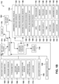
- FIG. 1B depicts a high-level block diagram of a UAS emissions measurement system 112, according to one embodiment.
- the system 112 may include a UAV 104.
- the UAV 104 may be a quadcopter-style aerial vehicle capable of hovering and flying the raster pattern flight path, as shown in FIG. 1A .
- the UAV 104 may be a winged aerial vehicle.
- the UAV 104 may have any number of rotors, motors 128, wings, or the like to sustain flight and fly the determined UAV flight path.
- the UAV 104 may have the ability to fly in a three-dimensional flight path in the vicinity of a potential methane source (108, FIG. 1A ).
- the UAV 104 may fly ⁇ 200m from a 0.1 SCFH emissions point.
- Embodiments of the unmanned aerial vehicle 104 may include any number of sensors shown in FIG. 1B based on the desired data.
- Embodiments of the weather station 154 may include any number of sensors shown in FIG. 1B based on the desired data.
- the weather station 154 may only include an anemometer 160.
- the weather station 154 may be integrated into the unmanned aerial vehicle 104.
- the anemometer 160 may be integrated on the unmanned aerial vehicle 104.
- the weather station 154 may be located on another aerial vehicle or unmanned aerial vehicle.
- the system may include two or more unmanned aerial vehicles where at least one unmanned aerial vehicle is recording methane gas concentrations and at least one unmanned aerial vehicle is recording meteorological data.
- the weather station 154 may be stationary or mobile. The weather station 154 may be in relatively close proximity to the unmanned aerial vehicle 104. In some embodiments, the weather station 154 may record meteorological data. In some embodiments, the weather station 154 may be from a third-party source, such as a third-party sensor. In some embodiments, the weather station 154 may predict future meteorological measurements.
- the nearest temporal Meteorological (MET) data packet 174 may be combined with the UAV data packet 152. The frequency of each of the MET data packet 174 and the UAV data packet 152 may be different but close in some embodiments. The frequency of each of the MET data packet 174 and the UAV data packet 152 may be substantially the same in some embodiments.
- the UAV 104 may have a global positioning system 114, an onboard avionics 117, and/or a location sensor 118 to track a spatial position of the UAV 104 as it travels along the flight path (102, FIG. 1A ).
- the UAV 104 may track its spatial position as it measures gas concentrations along the flight path such that each gas measurement of the UAV 104 corresponds to a spatial position where that gas measurement was taken.
- the global positioning system 114, onboard avionics 117, and/or location sensor 118 may be in communication with a UAV processor 116 having addressable memory 118.
- the location of the UAV 104 may be determined by the onboard avionics 117.
- the onboard avionics 117 may include a triangulation system, a beacon, a spatial coordinate system, or the like.
- the onboard avionics 117 may be used with the GPS 114 and/or location sensor 118 in some embodiments. In other embodiments, the UAV 104 may use only one of the GPS 114, the onboard avionics 117, and/or the location sensor 118.
- the UAV 104 may include a payload 120 in communication with the UAV processor 116.
- the payload 120 may include one or more gas concentration sensors.
- the payload 120 may be detachably attached to the UAV 104. In other embodiments, the payload 120 may be fixedly attached to the UAV 104.
- the payload 120 may be in communication with the UAV processor 116.
- the UAV processor 116 may also be in communication with an orientation sensor 128, an inertial measurement unit (IMU) 130, an altitude sensor 132, a radar 134, a LIDAR 136, and/or a Sonar 138 for generating additional information on the spatial position of the UAV 104 during each gas measurement by the payload 120.
- the orientation sensor 128 may be used to determine an orientation of the UAV 104 relative to ground.
- the IMU 130 may be used to determine attitude, velocity and/or position of the UAV 104.
- the altitude sensor 132 may be used to determine an altitude of the UAV 104.
- the LIDAR 136, Sonar 138, and/or radar 134 may be used to determine a relative altitude of the UAV 104.
- the UAV processor 116 may also be in communication with an anemometer 142, one or more weather sensors 144, and/or a barometric pressure sensor 146.
- the anemometer 142 may be used to measure the speed of the wind.
- the anemometer 142 may be attached to the UAV 104 at a point so as to ensure an accurate wind measurement without interfering with the propulsion from the motors 128 or sensors of the payload 120.
- the weather sensor 144 may measure weather and/or atmospheric conditions.
- the barometric pressure sensor 146 may measure a barometric pressure.
- the anemometer 142, weather sensor 144, and/or barometric pressure sensor 146 may be used to record data at each gas measurement from the payload 120.
- the UAV processor 116 may also be in communication with a time measurement device 140.
- the time measurement device 140 may be used to record the time for each gas measurement measured by the payload 120 of the UAV 104.
- Each gas measurement, position measurement, orientation measurement, weather measurement, and/or relative altitude measurement may be 'time-stamped' so as to be combined by the processor 122 and/or the UAV processor 116.
- the UAV processor 116 may also be in communication with a transceiver 148 and/or a wireless radio 150.
- the transceiver 148 and/or wireless radio 150 may be used to communicate between the UAV 104 and the processor 122, the ground control station (GCS) 126, and/or a cloud server 124.
- GCS ground control station
- the processor determines a flight path for the UAV 104 having the payload 120.
- the flight path may be determined on a site-specific basis.
- the flight path may be self-determined, autonomous control.
- the flight path is used to measure gas concentration along a crosswind transect, and vertical profile, in the vicinity of a possible gas emissions point. This flight plane of the flight path is designed to capture the atmospheric methane background as well as emissions signature, i.e., elevated ambient concentration, from all potential sources at an inspection site.
- the UAV 104 may have the UAV processor 116 in communication with addressable memory 118, a GPS 114, one or more motors 128, and a power supply 130.
- the UAV 104 may communicate gathered payload 120 data to the UAV processor 116.
- the power supply 130 may be a battery in some embodiments.
- the processor 122 may be a part of the UAV 104, the cloud server 124, the GCS 126 used to control the UAV 104, or the like.
- a weather station 210 may provide local weather information to the UAV 202, payload 204, and/or GCS 206.
- the weather station 210 may also receive information from the UAV 202, GCS 206, and/or payload 204.
- the UAV 202 vehicle state and other information may be transmitted by the UAV 202 and received by the GCS 206.
- the GCS may send command and control information to the UAV 202.
- the payload 204 may provide and/or receive payload data between the payload 204 and the UAV 202 and/or the GCS 206.
- Spike detection on the concentration enhancement signal is performed as part of the emissions calculation to determine if an emission source is present upwind of the flight path. This is a binary determination step, after performing spike detection on the concentration enhancement signal the remaining portion of the emissions algorithm only continues if an upwind emission source is present.
- FIG. 12A depicts a graph 1200 of a flux plane average flight path vector 1202, average wind vector 1204, and derived normal wind component 1206, according to one embodiment.
- FIG. 12B depicts a graph 1201 of a modeled wind profile for the total wind 1208 and the derived orthogonal wind 1210.
- the Emissions Estimate algorithm determines the surface wind speed and direction utilizing measurements from the onsite 2D or 3D sonic anemometer. Due to local wind variability, it is necessary to derive the average and/or median normal wind component to the flown flux plane.
- the orthogonal wind component is utilized to model the local wind profile.
- the derived orthogonal wind profile 1210 is utilized in the emissions calculation.
- Information transferred via communications interface 1514 may be in the form of signals such as electronic, electromagnetic, optical, or other signals capable of being received by communications interface 1514, via a communication link 1516 that carries signals and may be implemented using wire or cable, fiber optics, a phone line, a cellular/mobile phone link, an radio frequency (RF) link, and/or other communication channels.
- Computer program instructions representing the block diagram and/or flowcharts herein may be loaded onto a computer, programmable data processing apparatus, or processing devices to cause a series of operations performed thereon to produce a computer implemented process.
- Embodiments have been described with reference to flowchart illustrations and/or block diagrams of methods, apparatus (systems) and computer program products according to embodiments.
- Each block of such illustrations/diagrams, or combinations thereof, can be implemented by computer program instructions.
- the computer program instructions when provided to a processor produce a machine, such that the instructions, which execute via the processor, create means for implementing the functions/operations specified in the flowchart and/or block diagram.
- Each block in the flowchart/block diagrams may represent a hardware and/or software module or logic, implementing embodiments. In alternative implementations, the functions noted in the blocks may occur out of the order noted in the figures, concurrently, etc.
- Computer programs are stored in main memory and/or secondary memory. Computer programs may also be received via a communications interface 1512. Such computer programs, when executed, enable the computer system to perform the features of the embodiments as discussed herein. In particular, the computer programs, when executed, enable the processor and/or multi-core processor to perform the features of the computer system. Such computer programs represent controllers of the computer system.
- FIG. 16 shows a block diagram of an example system 1600 in which an embodiment may be implemented.
- the system 1600 includes one or more client devices 1601 such as consumer electronics devices, connected to one or more server computing systems 1630.
- a server 1630 includes a bus 1602 or other communication mechanism for communicating information, and a processor (CPU) 1604 coupled with the bus 1602 for processing information.
- the server 1630 also includes a main memory 1606, such as a random access memory (RAM) or other dynamic storage device, coupled to the bus 1602 for storing information and instructions to be executed by the processor 1604.
- the main memory 1606 also may be used for storing temporary variables or other intermediate information during execution or instructions to be executed by the processor 1604.
- the server computer system 1630 further includes a read only memory (ROM) 1608 or other static storage device coupled to the bus 1602 for storing static information and instructions for the processor 1604.
- ROM read only memory
- a storage device 1610 such as a magnetic disk or optical disk, is provided and coupled to the bus 1602 for storing information and instructions.
- the bus 1602 may contain, for example, thirty-two address lines for addressing video memory or main memory 1606.
- the bus 1602 can also include, for example, a 32-bit data bus for transferring data between and among the components, such as the CPU 1604, the main memory 1606, video memory and the storage 1610. Alternatively, multiplex data/address lines may be used instead of separate data and address lines.
- the server 1630 may be coupled via the bus 1602 to a display 1612 for displaying information to a computer user.
- An input device 1614 is coupled to the bus 1602 for communicating information and command selections to the processor 1604.
- cursor control 1616 such as a mouse, a trackball, or cursor direction keys for communicating direction information and command selections to the processor 1604 and for controlling cursor movement on the display 1612.
- computer program medium “computer usable medium,” “computer readable medium”, and “computer program product,” are used to generally refer to media such as main memory, secondary memory, removable storage drive, a hard disk installed in hard disk drive, and signals. These computer program products are means for providing software to the computer system.
- the computer readable medium allows the computer system to read data, instructions, messages or message packets, and other computer readable information from the computer readable medium.
- the computer readable medium may include non-volatile memory, such as a floppy disk, ROM, flash memory, disk drive memory, a CD-ROM, and other permanent storage. It is useful, for example, for transporting information, such as data and computer instructions, between computer systems.
- the computer readable medium may comprise computer readable information in a transitory state medium such as a network link and/or a network interface, including a wired network or a wireless network that allow a computer to read such computer readable information.
- Computer programs also called computer control logic
- main memory and/or secondary memory Computer programs may also be received via a communications interface.
- Such computer programs when executed, enable the computer system to perform the features of the embodiments as discussed herein.
- the computer programs when executed, enable the processor multi-core processor to perform the features of the computer system. Accordingly, such computer programs represent controllers of the computer system.
- Non-volatile media includes, for example, optical or magnetic disks, such as the storage device 1610.
- Volatile media includes dynamic memory, such as the main memory 1606.
- Transmission media includes coaxial cables, copper wire and fiber optics, including the wires that comprise the bus 1602. Transmission media can also take the form of acoustic or light waves, such as those generated during radio wave and infrared data communications.
- Computer-readable media include, for example, a floppy disk, a flexible disk, hard disk, magnetic tape, or any other magnetic medium, a CD-ROM, any other optical medium, punch cards, paper tape, any other physical medium with patterns of holes, a RAM, a PROM, an EPROM, a FLASH-EPROM, any other memory chip or cartridge, a carrier wave as described hereinafter, or any other medium from which a computer can read.
- Various forms of computer readable media may be involved in carrying one or more sequences of one or more instructions to the processor 1604 for execution.
- the instructions may initially be carried on a magnetic disk of a remote computer.
- the remote computer can load the instructions into its dynamic memory and send the instructions over a telephone line using a modem.
- a modem local to the server 1630 can receive the data on the telephone line and use an infrared transmitter to convert the data to an infrared signal.
- An infrared detector coupled to the bus 1602 can receive the data carried in the infrared signal and place the data on the bus 1602.
- the bus 1602 carries the data to the main memory 1606, from which the processor 1604 retrieves and executes the instructions.
- the instructions received from the main memory 1606 may optionally be stored on the storage device 1610 either before or after execution by the processor 1604.
- the server 1630 also includes a communication interface 1618 coupled to the bus 1602.
- the communication interface 1618 provides a two-way data communication coupling to a network link 1620 that is connected to the world wide packet data communication network now commonly referred to as the Internet 1628.
- the Internet 1628 uses electrical, electromagnetic or optical signals that carry digital data streams.
- the signals through the various networks and the signals on the network link 1620 and through the communication interface 1618, which carry the digital data to and from the server 1630, are exemplary forms or carrier waves transporting the information.
- interface 1618 is connected to a network 1622 via a communication link 1620.
- the communication interface 1618 may be an integrated services digital network (ISDN) card or a modem to provide a data communication connection to a corresponding type of telephone line, which can comprise part of the network link 1620.
- ISDN integrated services digital network
- the communication interface 1618 may be a local area network (LAN) card to provide a data communication connection to a compatible LAN.
- LAN local area network
- Wireless links may also be implemented.
- the communication interface 1618 sends and receives electrical electromagnetic or optical signals that carry digital data streams representing various types of information.
- the network link 1620 typically provides data communication through one or more networks to other data devices.
- the network link 1620 may provide a connection through the local network 1622 to a host computer 1624 or to data equipment operated by an Internet Service Provider (ISP).
- ISP Internet Service Provider
- the ISP in turn provides data communication services through the Internet 1628.
- the local network 1622 and the Internet 1628 both use electrical, electromagnetic or optical signals that carry digital data streams.
- the signals through the various networks and the signals on the network link 1620 and through the communication interface 1618, which carry the digital data to and from the server 1630, are exemplary forms or carrier waves transporting the information.
- the server 1630 can send/receive messages and data, including e-mail, program code, through the network, the network link 1620 and the communication interface 1618.
- the communication interface 1618 can comprise a USB/Tuner and the network link 1620 may be an antenna or cable for connecting the server 1630 to a cable provider, satellite provider or other terrestrial transmission system for receiving messages, data and program code from another source.
- the example versions of the embodiments described herein may be implemented as logical operations in a distributed processing system such as the system 1600 including the servers 1630.
- the logical operations of the embodiments may be implemented as a sequence of steps executing in the server 1630, and as interconnected machine modules within the system 1600.
- the implementation is a matter of choice and can depend on performance of the system 1600 implementing the embodiments.
- the logical operations constituting said example versions of the embodiments are referred to for e.g., as operations, steps or modules.
- a client device 1601 can include a processor, memory, storage device, display, input device and communication interface (e.g., e-mail interface) for connecting the client device to the Internet 1628, the ISP, or LAN 1622, for communication with the servers 1630.
- a processor e.g., a processor, memory, storage device, display, input device and communication interface (e.g., e-mail interface) for connecting the client device to the Internet 1628, the ISP, or LAN 1622, for communication with the servers 1630.
- communication interface e.g., e-mail interface
- the system 1600 can further include computers (e.g., personal computers, computing nodes) 1605 operating in the same manner as client devices 1601, wherein a user can utilize one or more computers 1605 to manage data in the server 1630.
- computers e.g., personal computers, computing nodes
- cloud computing environment 50 comprises one or more cloud computing nodes 10 with which local computing devices used by cloud consumers, such as, for example, personal digital assistant (PDA), smartphone, smart watch, set-top box, video game system, tablet, mobile computing device, or cellular telephone 54A, desktop computer 54B, laptop computer 54C, and/or unmanned aerial system 54N may communicate.
- Nodes 10 may communicate with one another. They may be grouped (not shown) physically or virtually, in one or more networks, such as Private, Community, Public, or Hybrid clouds as described hereinabove, or a combination thereof.
- cloud computing environment 50 to offer infrastructure, platforms and/or software as services for which a cloud consumer does not need to maintain resources on a local computing device. It is understood that the types of computing devices 54A-N shown in FIG. 17 are intended to be illustrative only and that computing nodes 10 and cloud computing environment 50 can communicate with any type of computerized device over any type of network and/or network addressable connection (e.g., using a web browser).
Landscapes
- Engineering & Computer Science (AREA)
- Chemical & Material Sciences (AREA)
- Life Sciences & Earth Sciences (AREA)
- Health & Medical Sciences (AREA)
- Physics & Mathematics (AREA)
- General Physics & Mathematics (AREA)
- Aviation & Aerospace Engineering (AREA)
- Signal Processing (AREA)
- Analytical Chemistry (AREA)
- Biochemistry (AREA)
- Combustion & Propulsion (AREA)
- Pathology (AREA)
- Immunology (AREA)
- Food Science & Technology (AREA)
- Medicinal Chemistry (AREA)
- General Health & Medical Sciences (AREA)
- Radar, Positioning & Navigation (AREA)
- Automation & Control Theory (AREA)
- Remote Sensing (AREA)
- Computer Networks & Wireless Communication (AREA)
- Arrangements For Transmission Of Measured Signals (AREA)
- Traffic Control Systems (AREA)
Description
- Embodiments relate generally to methane concentration measurement, and more particularly to Unmanned Aerial System (UAS) methane concentration measurement.
- Methane (CH4) is an odorless and colorless naturally occurring organic molecule, which is present in the atmosphere at average ambient levels of approximately 1.85 ppm as of 2018 and is projected to continually climb. While methane is found globally in the atmosphere, a significant amount is collected or "produced" through anthropogenic processes including exploration, extraction, and distribution of petroleum in the form of natural gas. Natural gas, an odorless and colorless gas, is a primary source of energy used to produce electricity and heat. The main component of natural gas is methane (93.9 mol % CH4 typ.). While extraction of natural gas is a large source of methane released to atmosphere, major contributors of methane also include livestock farming (enteric fermentation), and solid waste and wastewater treatment (anaerobic digestion).
WO 2017/069979 A1 discloses an apparatus and method for detecting the location of sources of one or more target molecule, the apparatus comprising: a molecule detector; and a processor connected to the molecule detector and to a global position system, wherein the processor calculates the presence of the one or more target molecules, runs a computer code that determines a dynamic reverse gas stack model for the one or more target molecules, and triangulates the possible position for a source or effluent of the one or more target molecules based on the dynamic reverse gas stack model. The determined reverse gas stack model may have a Gaussian dispersion over one or more sampled locations.
US 2017/134497 A1 discloses a process for detecting media dispersion. The process detects the dispersion of contaminants through distributed remote sensor platforms that connect one or more sensors on a remote device. The process generates a plume model in response to the detection data and meteorological data that models dispersion plumes and activates and deactivates selected sensors in response to a forecasted to dispersion area. - According to a first aspect of the invention a system is provided as recited in
claim 1. - Additional system embodiments may include: a display in communication with the processor, where the display may be configured to show the determined methane emission rate of the methane source on a map. In additional system embodiments, the map may be at least one of: a satellite image, an aerial image, a two-dimensional color map, a two-dimensional contour map, and a three-dimensional topographical surface.
- Additional system embodiments may include: a payload of a UAV, where the payload may include one or more gas concentration sensors configured to generate the methane concentration data along the UAV flight path. In additional system embodiments, the UAV information along the UAV flight path may include at least one of: a location of the UAV, a time corresponding to the location of the UAV, a barometric pressure, an altitude, a relative altitude, and an orientation of the UAV, and where the UAV information along the UAV flight path corresponds to the generated methane concentration data along the UAV flight path. In additional system embodiments, the location of the UAV may be determined by at least one of: a global positioning system (GPS), an onboard avionics, and a location sensor. In additional system embodiments, the relative altitude of the UAV may be determined by at least one of: an altitude of a global positioning system (GPS), a LIDAR, a Sonar, a radar, and a barometric pressure sensor. In additional system embodiments, the orientation of the UAV may be determined by at least one of: an inertial measurement unit (IMU) and an orientation sensor.
- Additional system embodiments may include: one or more weather stations, where each weather station generates the Meteorological data packet. In additional system embodiments, the Meteorological Data Packet may include data from at least one of: an anemometer, one or more pressure sensors, a pryanometer, a ground temperature sensor, an air temperature sensor, and a current atmospheric condition sensor. In additional system embodiments, at least one of: a ground control station (GCS), a cloud server, the UAV, and the weather station may include the processor. In additional system embodiments, the determined methane emission rate may be stored by at least one of: a ground control station (GCS) and a cloud server.
- According to a second aspect of the invention a method is provided as recited in
claim 10. - Additional method embodiments may include: measuring, by a payload of a UAV, the methane concentration data along the UAV flight path, where the payload comprises one or more gas concentration sensors; generating, by the UAV, the UAV data packet, where the UAV data packet comprises a spatial position of the UAV at each methane concentration data measurement; and generating, by a weather station of one or more weather stations, the Meteorological data packet; where the UAV data packet comprises data from at least one of: a weather sensor, an onboard avionics, a barometric pressure sensor, an orientation sensor, an intertial measurement unit (IMU), a wireless radio, a global positioning system (GPS), a time measurement device, an altitude sensor, a location sensor, a radar, a lidar, an anemometer, an a Sonar; and where the Meteorological data packet comprises data from at least one of: an anemometer, one or more pressure sensors, a pryanometer, a ground temperature sensor, an air temperature sensor, and a current atmospheric condition sensor.
- There is also disclosed as an illustrative example not forming part fo the invention a system including: an unmanned aerial vehicle configured to generate a UAV data packet; a payload of the UAV, where the payload comprises one or more gas concentration sensors configured to generate the methane concentration data along a UAV flight path; one or more sensors of the UAV, where the one or more sensors of the UAV are configured to generate UAV information; one or more weather stations, where each weather station generates a Meteorological data packet, where the Meteorological data packet comprises weather data from one or more sensors of the weather station; and a processor having addressable memory, the processor in communication with the UAV and the one or more weather stations, where the processor configured to: receive the UAV data packet, where the UAV data packet comprises methane concentration data from the payload and UAV information the one or more sensors of the UAV; receive at least one Meteorological data packet; combine the UAV data packet with a nearest
- Meteorological data packet; determine a methane emission rate of a methane source based on the combined UAV data packet and the nearest Meteorological data packet; and show the determined methane emission rate of the methane source on a map via a display in communication with the processor.
- The components in the figures are not necessarily to scale, emphasis instead being placed upon illustrating the principals of the invention. Like reference numerals designate corresponding parts throughout the different views. Embodiments are illustrated by way of example and not limitation in the figures of the accompanying drawings, in which:
-
FIG. 1A depicts an illustration of an unmanned aerial system (UAS) emissions measurement process and flight path, according to one embodiment. -
FIG. 1B depicts a high-level block diagram of a UAS emissions measurement system, according to one embodiment. -
FIG. 1C depicts a high-level flowchart of a method embodiment of determining emissions measurements via unmanned aerial vehicle (UAV) data and weather data, according to one embodiment. -
FIG. 2 depicts a data flow in a single sensor and unmanned aerial vehicle (UAV) configuration with a Ground Control Station (GCS) as a point of interface between the UAS and the cloud-connected Processor, Local Server Processor, and/or Database, according to one embodiment. -
FIG. 3 depicts a data flow in a single sensor and UAV configuration with the UAS directly interfacing with the cloud-connected Processor, Local Server Processor, and/or Database, according to one embodiment. -
FIG. 4 depicts a detailed data transfer from a single sensor with a single UAV, where this combination of devices comprise a UAS, according to one embodiment. -
FIG. 5 depicts a background gas concentration workflow, according to one embodiment. -
FIG. 6A depicts a graph showing raw concentration data, filtered/interpolated data, and a background concentration estimation, according to one embodiment. -
FIG. 6B depicts a graph showing a concentration enhancement data resolved utilizing a sliding window median filter, according to one embodiment. -
FIG. 7 depicts a plane projection workflow, according to one embodiment. -
FIG. 8 depicts formulas for an orthogonal vector projection, according to one embodiment. -
FIG. 9A depicts an overhead view of the flux plane flight trajectory with a derived regression line used for projection, according to one embodiment. -
FIG. 9B depicts a flight trajectory projected onto the (y, z) plane, according to one embodiment. -
FIG. 10A depicts projected values along the (y, z) plane, according to one embodiment. -
FIG. 10B depicts an averaged and interpolated flux plane, according to one embodiment. -
FIG. 11 depicts a diagram illustrating the primary surface level sublayers in the Atmospheric Boundary Layer, according to one embodiment. -
FIG. 12A depicts a flux plane average flight path vector, average wind vector, and derived normal wind component, according to one embodiment. -
FIG. 12B depicts a modeled wind profile for the total wind and the derived orthogonal wind. -
FIG. 13 depicts a schematic drawing of an Emissions Estimate Model, according to one embodiment. -
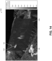
FIG. 14 depicts a 3-dimensional illustration of a UAS system Emissions measurement process, according to one embodiment. -
FIG. 15 shows a high-level block diagram and process of a computing system for implementing an embodiment of the system and process. -
FIG. 16 shows a block diagram and process of an exemplary system in which an embodiment may be implemented. -
FIG. 17 depicts a cloud computing environment for implementing an embodiment of the system and process disclosed herein - The following description is made for the purpose of illustrating the general principles of the embodiments discloses herein and is not meant to limit the concepts disclosed herein. Further, particular features described herein can be used in combination with other described features in each of the various possible combinations and permutations. Unless otherwise specifically defined herein, all terms are to be given their broadest possible interpretation including meanings implied from the description as well as meanings understood by those skilled in the art and/or as defined in dictionaries, treatises, etc.
- The present system and method disclosed herein allow for determining a methane emission rate of a methane source based on measurements from one or more sensors mounted on an unmanned aerial vehicle (UAV), UAV data, and one or more sensors from one or more weather stations. The UAV flies in a raster grid pattern flight path downwind of the methane source. The path of the flight pattern is substantially perpendicular to a ground surface and an average wind direction to measure methane emissions downwind of the methane source. Data from the one or more UAV sensors, the UAV data, and the one or more sensors from the one or more weather stations may be combined, stored, processed, and/or filtered to determine the methane emission rate of the methane source.
- The goal of the natural gas production and supply chain is to deliver gas from source production areas to endpoint users without undue loss. Product loss in this context amounts to flaring or venting, intentional or otherwise, of natural gas to the atmosphere. Undue product loss results in uncaptured revenue, an increased environmental footprint, and possible safety hazards for vented emissions. There are many opportunities throughout the natural gas production and supply chain for gas to be released from containment and lost, such as pneumatic component venting, maintenance blowdowns, component failures, accidental release, and the like. Natural gas production and distribution infrastructure are spatially distributed. Efficient, wide area survey methods are needed to identify, localize, and quantify natural gas releases throughout these spatially distributed systems.
- The disclosed unmanned aerial system (UAS) measures methane concentration along the chosen UAV flight path at high frequency to detect anomalies associated with natural gas releases. Data from the UAV may be reconciled with atmospheric conditions to identify and quantify the mass flow rate of natural gas sources within an inspection area.
- The disclosed method for emission rate quantification is based on an engineering control volume model. The UAS has a fast response, in situ methane sensor payload and flies downwind of potential emission sources on transects that are nearly perpendicular to the average wind direction approximately +/- 90 degrees. The disclosed sensors measure the crosswind and vertical profile of methane concentration and maps out the spatial profile of methane emissions from upwind sources as well as the characteristics of the background concentration variability.
-
FIG. 1A depicts an illustration of an unmanned aerial system (UAS) emissions measurement process andflight path 100, according to one embodiment. Arepresentative flight path 102 of an unmanned aerial vehicle (UAV) 104 is downwind of apoint source 108. In this example, thepoint source 108 is a pump jack, but thepoint source 108 may be any equipment having a potential to emit gas. TheUAV 104 measures a cross-section of anemissions plume 106 from thepoint source 108 on a vertical plane. In addition to concentration, emission rate estimates are determined by wind velocity along theUAV flight path 102. - To capture a downwind "control surface" for the emissions estimate, the disclosed
UAV 104 flies a raster gridpattern flight path 102 along a vertical plane that is perpendicular to aground surface 110 and the average wind direction +/- 90 degrees. The position of theUAV 104 and corresponding natural gas concentration measurement are recorded, such as by a global positioning system (GPS) position. The altitude of theUAV 104 relative to theground 110 may be further quantified using a range-finding LIDAR, Sonar, radar, GPS altitude, and/or barometric pressure sensor. -
FIG. 1B depicts a high-level block diagram of a UASemissions measurement system 112, according to one embodiment. Thesystem 112 may include aUAV 104. In some embodiments, theUAV 104 may be a quadcopter-style aerial vehicle capable of hovering and flying the raster pattern flight path, as shown inFIG. 1A . In other embodiments, theUAV 104 may be a winged aerial vehicle. TheUAV 104 may have any number of rotors,motors 128, wings, or the like to sustain flight and fly the determined UAV flight path. TheUAV 104 may have the ability to fly in a three-dimensional flight path in the vicinity of a potential methane source (108,FIG. 1A ). TheUAV 104 may fly ≤200m from a 0.1 SCFH emissions point. - Embodiments of the unmanned
aerial vehicle 104 may include any number of sensors shown inFIG. 1B based on the desired data. Embodiments of theweather station 154 may include any number of sensors shown inFIG. 1B based on the desired data. In some embodiments, theweather station 154 may only include ananemometer 160. In other embodiments, theweather station 154 may be integrated into the unmannedaerial vehicle 104. For example, theanemometer 160 may be integrated on the unmannedaerial vehicle 104. In another embodiment, theweather station 154 may be located on another aerial vehicle or unmanned aerial vehicle. For example, the system may include two or more unmanned aerial vehicles where at least one unmanned aerial vehicle is recording methane gas concentrations and at least one unmanned aerial vehicle is recording meteorological data. Theweather station 154 may be stationary or mobile. Theweather station 154 may be in relatively close proximity to the unmannedaerial vehicle 104. In some embodiments, theweather station 154 may record meteorological data. In some embodiments, theweather station 154 may be from a third-party source, such as a third-party sensor. In some embodiments, theweather station 154 may predict future meteorological measurements. The nearest temporal Meteorological (MET)data packet 174 may be combined with theUAV data packet 152. The frequency of each of theMET data packet 174 and theUAV data packet 152 may be different but close in some embodiments. The frequency of each of theMET data packet 174 and theUAV data packet 152 may be substantially the same in some embodiments. - The
UAV 104 may have aglobal positioning system 114, anonboard avionics 117, and/or alocation sensor 118 to track a spatial position of theUAV 104 as it travels along the flight path (102,FIG. 1A ). TheUAV 104 may track its spatial position as it measures gas concentrations along the flight path such that each gas measurement of theUAV 104 corresponds to a spatial position where that gas measurement was taken. Theglobal positioning system 114,onboard avionics 117, and/orlocation sensor 118 may be in communication with aUAV processor 116 havingaddressable memory 118. In some embodiments, the location of theUAV 104 may be determined by theonboard avionics 117. Theonboard avionics 117 may include a triangulation system, a beacon, a spatial coordinate system, or the like. Theonboard avionics 117 may be used with theGPS 114 and/orlocation sensor 118 in some embodiments. In other embodiments, theUAV 104 may use only one of theGPS 114, theonboard avionics 117, and/or thelocation sensor 118. - The
UAV 104 may include apayload 120 in communication with theUAV processor 116. Thepayload 120 may include one or more gas concentration sensors. Thepayload 120 may be detachably attached to theUAV 104. In other embodiments, thepayload 120 may be fixedly attached to theUAV 104. Thepayload 120 may be in communication with theUAV processor 116. In one embodiment, thepayload 120 may be an ultra-lightweight, low power, Part per Billion (ppb) sensitivity, mid-Infrared (λ = 3 - 8µm), open path methane concentration sensor with sampling rate > 0.1 Hz. - The
UAV processor 116 may also be in communication with anorientation sensor 128, an inertial measurement unit (IMU) 130, analtitude sensor 132, aradar 134, aLIDAR 136, and/or aSonar 138 for generating additional information on the spatial position of theUAV 104 during each gas measurement by thepayload 120. Theorientation sensor 128 may be used to determine an orientation of theUAV 104 relative to ground. TheIMU 130 may be used to determine attitude, velocity and/or position of theUAV 104. Thealtitude sensor 132 may be used to determine an altitude of theUAV 104. TheLIDAR 136,Sonar 138, and/orradar 134 may be used to determine a relative altitude of theUAV 104. - In some embodiments, the
UAV processor 116 may also be in communication with ananemometer 142, one ormore weather sensors 144, and/or abarometric pressure sensor 146. Theanemometer 142 may be used to measure the speed of the wind. Theanemometer 142 may be attached to theUAV 104 at a point so as to ensure an accurate wind measurement without interfering with the propulsion from themotors 128 or sensors of thepayload 120. Theweather sensor 144 may measure weather and/or atmospheric conditions. Thebarometric pressure sensor 146 may measure a barometric pressure. Theanemometer 142,weather sensor 144, and/orbarometric pressure sensor 146 may be used to record data at each gas measurement from thepayload 120. - In some embodiments, the
UAV processor 116 may also be in communication with atime measurement device 140. Thetime measurement device 140 may be used to record the time for each gas measurement measured by thepayload 120 of theUAV 104. Each gas measurement, position measurement, orientation measurement, weather measurement, and/or relative altitude measurement may be 'time-stamped' so as to be combined by theprocessor 122 and/or theUAV processor 116. - The
UAV processor 116 may also be in communication with atransceiver 148 and/or awireless radio 150. Thetransceiver 148 and/orwireless radio 150 may be used to communicate between theUAV 104 and theprocessor 122, the ground control station (GCS) 126, and/or acloud server 124. - The processor determines a flight path for the
UAV 104 having thepayload 120. In some embodiments, the flight path may be determined on a site-specific basis. In other embodiments, the flight path may be self-determined, autonomous control. The flight path is used to measure gas concentration along a crosswind transect, and vertical profile, in the vicinity of a possible gas emissions point. This flight plane of the flight path is designed to capture the atmospheric methane background as well as emissions signature, i.e., elevated ambient concentration, from all potential sources at an inspection site. - The
UAV 104 may have theUAV processor 116 in communication withaddressable memory 118, aGPS 114, one ormore motors 128, and apower supply 130. TheUAV 104 may communicate gatheredpayload 120 data to theUAV processor 116. Thepower supply 130 may be a battery in some embodiments. In some embodiments, theprocessor 122 may be a part of theUAV 104, thecloud server 124, theGCS 126 used to control theUAV 104, or the like. - The
UAV processor 116 may receive gas data from the one or more gas sensors of thepayload 120. TheUAV processor 116 may also receive spatial position data from theGPS 112,altitude sensor 132,location sensor 118,radar 134,LIDAR 136,Sonar 138,orientation sensor 128,IMU 130, and/oronboard avionics 117. In some embodiments, theUAV processor 116 may also receive weather data from theweather sensor 144, thebarometric pressure sensor 146, and/or the anemometer. TheUAV processor 116 may also receive the time from thetime measurement device 140. TheUAV processor 116 may fuse the gas data from thepayload 120 with theUAV 104 spatial position data, weather data, and/or time to form aUAV Data Packet 152. - The
UAV data packet 152 may be sent to theprocessor 122,ground control station 126, and/orcloud server 124 via thetransceiver 148 and/orwireless radio 150. In some embodiments, thewireless radio 150 or cellular connection may be used for remote data transfer between theUAV 104, theGCS 126, theprocessor 122, and/or thecloud server 124. The wireless interface or cellular connection between theUAV 104, theGCS 126, theprocessor 122, and/or thecloud server 124 may be used to performing advanced data analysis functions. Direct, bidirectional data transfer may occur between theUAV 104 and theGCS 126, between theUAV 104 and thecloud server 124, and/or between theGCS 124 and thecloud server 124. - The
processor 122 may be a part of theUAV 104, theGCS 126, thecloud server 124, and/or theweather station 154 in some embodiments. While multiple sensors and devices are depicted for theUAV 104, any number of sensors and/or devices may be used based on thesystem 112, desired accuracy, time limitations, weight limitations, and the like. - One or
more weather stations UAV 104,payload 120,GCS 126, and/orcloud server 124. Theweather stations UAV 104,payload 120,GCS 126, and/orcloud server 124. - The
first weather station 154 may include one ormore anemometers 160, one ormore pressure sensors 162, one or more pyranometers 164, one or moreground temperature sensors 166, one or moreair temperature sensors 168, one or moreatmospheric condition sensors 170, and one ormore location sensors 172. The anemometer may be used to measure wind speed. Thepressure sensor 162 may measure a pressure. The pyranometer may be used to measure solar irradiance. Theground temperature sensor 166 may be used to measure a temperature of the ground. Theair temperature sensor 168 may be used to measure a temperature of the air. Anatmospheric condition sensor 170 may be used to measure data relating to the atmosphere. Thelocation sensor 172 may be used to measure the location of theweather station 154. Eachweather station system 112, desired accuracy, number of weather stations over a geographical area, and the like. - In some embodiments, sensors and/or devices of the
weather station 154 may be located and/or duplicated on theUAV 104. High resolution (<0.1 m/s), high-frequency measurements (> 5 Hz) of wind speed and direction may be recorded using one or more wind sensors, and one or more additional weather/micro-meteorological sensors including, air temperature, humidity, atmospheric pressure, solar irradiance, ground surface temperature - from the ground via aweather station UAV 104 as disclosed herein. For example, both theweather station 154 and theUAV 104 may includerespective anemometers data packet 174. TheMeteorological data packet 174 may be sent to theprocessor 122,ground control station 126,cloud server 124, and/orUAV 104. TheMeteorological data packet 174 may include measurements and/or predictions of the atmosphere, weather, temperature, wind patterns, or the like. - Each
UAV Data Packet 152 may be combined with the nearest temporalMeteorological Data Packet 174 by theprocessor 122 and saved on theGCS 126 and/orcloud server 124. The data may be uploaded to thecloud server 124 in real-time, near real-time, or at a later time. The combinedUAV data packet 152 andMeteorological data packet 174 may be used to determine a methane emission rate of the methane source by theprocessor 122,GCS 126, and/orcloud server 124. The methane emission rate may be determined based on a control volume model that combines concentration measurements from the UAV flight plane with measured wind speed, direction and spatial gradient to determine the mass flow rate emissions from sources in the inspection area. - This determined methane emission rate may be stored by the
processor 122,GCS 126, and/orcloud server 124. In some embodiments, the determined emission rate may be shown on adisplay 176. Thedisplay 176 may show source emissions data on a map, satellite image, aerial image, two-dimensional color map, two-dimensional contour map, and/or three-dimensional topographical surface / mesh. -
FIG. 1C depicts a high-level flowchart of amethod 178 embodiment of determining emissions measurements via unmanned aerial vehicle (UAV) data and weather data, according to one embodiment. Themethod 178 includes determining, by a processor, a flight path of a UAV downwind of a methane source (step 180). Themethod 178 may then include generating a UAV data packet include a measured methane concentration and UAV information from the determined flight path (step 182). Themethod 178 may then include generating, by a weather station, a Meteorological data packet including data measured by theweather station 184. Themethod 178 includes receiving, by the processor, the UAV data packet and the Meteorological data packet (step 186). The method includes combining, by the processor, the received UAV data packet with a nearest temporal, i.e., in time, received Meteorological data packet (step 188). Themethod 178 includes determining, by the processor, a methane emission rate of the methane source based on the combined received UAV data packet and the Meteorological data packet (step 190). Themethod 178 may then include sending, by the processor, the determined emission rate of the methane source to a cloud server (step 192). -
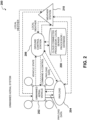
FIG. 2 depicts adata flow 200 in a single sensor and unmanned aerial vehicle (UAV) 202 configuration with a ground control station (GCS) 206 as a point of interface between theUAV 202 and the cloud-connected processor, local server processor, and/ordatabase 208, according to one embodiment. The general flow of data is from one or more gas concentration sensors, i.e.,payload 204, affixed to one ormore UAVs 202 and wirelessly transmitted to thecentralized GCS 206 and then transferred to the cloud-connected Server, Processer, Local Server Processor, and/orDatabase 206. - A
weather station 210 may provide local weather information to theUAV 202,payload 204, and/orGCS 206. Theweather station 210 may also receive information from theUAV 202,GCS 206, and/orpayload 204. TheUAV 202 vehicle state and other information may be transmitted by theUAV 202 and received by theGCS 206. The GCS may send command and control information to theUAV 202. Thepayload 204 may provide and/or receive payload data between thepayload 204 and theUAV 202 and/or theGCS 206. -
FIG. 3 depicts adata flow 300 in a single sensor andUAV 202 configuration with theUAV 202 directly interfacing with the cloud-connected processor, local server processor, and/ordatabase 208, according to one embodiment. In another embodiment, the payload(s) 204, UAV(s) 202, and/or weather station(s) 210 communicate directly with a cloud server processor, local server processor, and/ordatabase 208. In all cases, each subsystem, i.e.,UAV 202;payload 204; GCS (seeFIG. 2 ); cloud server processor, local server processor, and/ordatabase 208; andweather station 210, may or may not have the ability to directly communicate with each other subsystem, as shown inFIGS. 1A-2 . At the GCS (seeFIG. 2 ), and/or cloud server processor, local server processor, and/ordatabase 208, the data from thepayload 204 is coupled withlocal weather station 210 data through local private networks and/or publicly available over the Internet. The data can then be post-processed on the GCS (seeFIG. 2 ), on a local server, and/or on a cloud-hostedserver 208. -
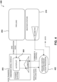
FIG. 4 depicts adetailed data transfer 400 from a single sensor with asingle UAV 202, where this combination of devices comprise a UAS, according to one embodiment. Data from thepayload 204 transfers to theUAV 202 and directly to anautopilot 404 via a serial connection. In some embodiments, the data transfer from theUAV 202 to theautopilot 404 may be any connection hardwire or wireless. Then, the data transfer is fused with GPS location and time, barometric pressure, altitude, relative altitude from LiDAR, Sonar, Radar, and/or UAV orientation, which forms a UAV Data Packet. The UAV Data Packet may be transferred to the GCS and/orcloud processor 402 via a 500mW 915MHz Frequency Hopping Spread Spectrum (FHSS) transceiver. In some embodiments, the UAV Data Packet may be transferred via any wireless radio. In parallel, aweather station 210 having at least an anemometer, and may contain one or more pressure sensors, pyranometers, i.e., for solar irradiance, ground temperature sensors, air temperature sensors, and/or any sensor necessary for quantifying current atmospheric conditions, may form a Meteorological Data Packet. The GCS and/orcloud processor 402 receives both the Meteorological Data Packet and UAV Data Packet at a frequency greater than 0.1 Hz. Each UAV Data Packet is fused with the nearest temporal Meteorological Data Packet and saved on the GCS and/or a cloud server, local server, and/ordatabase 402 in an ASCII, binary, or any file necessary. The data may be uploaded to a cloud server in real-time, near real-time, or at a later time. -
FIG. 5 depicts a backgroundgas concentration workflow 500, according to one embodiment. The first step in the emissions estimate model is to calculate the control volume in-flow condition. The in-flow condition will determine total emissions for the source area that is of interested, by accounting for and subtracting any emissions from upwind sources. Typically, it is assumed that the background concentration measured on the upwind side of the source inspection area is a good representation of the local background concentration and provides an estimate of the upwind in-flow condition. The procedure for calculating the background concentration starts with selecting data for the appropriate time period (step 502). Then, the GPS coordinates, i.e., longitude and latitude, are framed to along a path distance (step 504). Third, a statistical filter is applied to the concentration data (step 506). -
FIG. 6A depicts agraph 600 showingraw concentration data 602, filtered/interpolateddata 604, and abackground concentration estimation 606, according to one embodiment.FIG. 6B depicts agraph 608 showing a concentration enhancement data resolved utilizing a sliding window median filter, according to one embodiment. The raw concentration data as a function of distance, i.e., spatial coordinate, is filtered using a sliding window median filter. The filter window scale is determined based on a typical, or expected, gas plume width. For example, if the maximum plume width is expected to be on the order of 10m, the filter scale would be set to three to five times the max plume width. The median filter also removes infrequent transients, or dropouts, in the concentration measurement caused by communication interference, or platform vibrations. The background concentration is subtracted from the total concentration to obtain the concentration enhancement. The concentration enhancement signal represents the signature of an upwind emission source and is used to quantify the emissions released by the local source. - Spike detection on the concentration enhancement signal is performed as part of the emissions calculation to determine if an emission source is present upwind of the flight path. This is a binary determination step, after performing spike detection on the concentration enhancement signal the remaining portion of the emissions algorithm only continues if an upwind emission source is present.
- A statistical filter is then applied to the concentration enhancement signal to identify "spikes" in the data that indicate methane plumes from nearby sources. The statistical filter is determined by analysis of the Cumulative Distribution Function (CDF) for the concentration enhancement, and targets extremum data points based on a prescribed percentile threshold. The selected points are then analyzed for contiguity and consolidated to form spatially continuous events. Each spike event may be further analyzed according to other metrics such as spatial extent, amplitude, magnitude, variance, and waveform shape. Individual spike events may be included or excluded through a selection process based on these derived quantities.
-
FIG. 7 depicts aplane projection workflow 700, according to one embodiment. Due to variability in the flight trajectory caused by wind and GPS uncertainty, it is not generally possible to fly perfect transects along the same line at various heights. Therefore, an automatic detection of the nominal flight path, or plane, orientation may be performed using a least-squares fitting method to the data. First, data is selected for the appropriate time period (step 702). Then, a GPS coordinate, i.e., longitude and latitude, frame is converted to a Cartesian frame, i.e., x and y (step 704). Then, the nominal flight path is calculated, e.g., least squares (step 706). Finally, the data is projected onto the nominal control surface coordinate, i.e., y (step 708). -
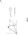
FIG. 8 depictsformulas 800 for an orthogonal vector projection, according to one embodiment. The projection is accomplished utilizing a linear algebra vector projection equation. Other projected vector formulas are possible and contemplated to determine the vector projection. Gamma (γ) is the vector norm, which is the length of the vector, as shown inFIG. 8 . -
FIG. 9A depicts agraph 900 of an overhead view of the flux plane flight trajectory with derived nominal flight plane trajectory used for projection, according to one embodiment.FIG. 9B depicts agraph 901 of a flight trajectory projected onto the (y,z) plane, according to one embodiment. Theline 902 in theFIG. 9A represents the best estimate for the nominal flight plane trajectory, onto which the measurement coordinates are projected.FIG. 9B shows the vertical profile of concentration measurements as a function of the projected flight plane coordinate, i.e., gamma, and the altitude. -
FIG. 10A depicts agraph 1000 of projected values along the (y, z) plane, according to one embodiment.FIG. 10B depicts agraph 1001 of an averaged and interpolated flux plane, according to one embodiment. Once the background concentration value is measured or estimated, the value is subtracted at each point along the flight path to obtain the concentration enhancement, and the measurements are averaged and interpolated on a continuous grid across the flight plane. A grid is created with a specified resolution over the range of coordinates in the projected flight plane. The concentration measurements within each grid cell are averaged, if no measurements exist for a particular grid cell then the value is left empty or replaced with null. After the grid is populated with the average measurements, a linear interpolation is applied to fill the grid with continuous concentration values. Some values on the grid have a negative concentration enhancement, this is important to ensure that the calculation returns a zero value for the flux when no upwind emission source is present. -
FIG. 11 depicts a diagram 1100 illustrating the primary surface level sublayers in the Atmospheric Boundary Layer, according to one embodiment. An important input to the Emissions Estimate model disclosed herein is wind speed. Most of the measurements made by the disclosed UAS will be performed within the Roughness Sublayer portion of the atmospheric sublayer, i.e., the region from the surface to just above the average obstruction height or the local topography. In this region, the standard log law vertical wind gradient model provides a reasonable approximation of the vertical wind profile. Vertical wind profile may be approximated using a log law. Other ways of determining the vertical wind profile given the wind at a certain height and projected altitude are possible and contemplated. In some embodiments, the vertical wind profile may be measured directly. The vertical wind gradient or the vertical wind model may be determined based on the meteorological data measured, recorded, and/or predicted. -
FIG. 12A depicts agraph 1200 of a flux plane averageflight path vector 1202,average wind vector 1204, and derivednormal wind component 1206, according to one embodiment.FIG. 12B depicts agraph 1201 of a modeled wind profile for thetotal wind 1208 and the derivedorthogonal wind 1210. The Emissions Estimate algorithm determines the surface wind speed and direction utilizing measurements from the onsite 2D or 3D sonic anemometer. Due to local wind variability, it is necessary to derive the average and/or median normal wind component to the flown flux plane. The orthogonal wind component is utilized to model the local wind profile. The derivedorthogonal wind profile 1210 is utilized in the emissions calculation. -
FIG. 13 depicts aschematic drawing 1300 of an Emissions Estimate Model, according to one embodiment. The Emissions Estimate algorithm is based on an engineering control volume model. This means that the two key inputs to the model are the concentration profile on the outflow surface, and the wind speed through the outflow. The concentration enhancement is measured by the disclosed sensor in volumetric concentration units, i.e., ppmv. To determine the source emission rate, it is necessary to convert from volumetric concentration to mass concentration, this is accomplished through the ideal gas law. The ideal gas law is used to calculate the air density based on the local air temperature and atmospheric pressure. At or below about 1% methane in air, the contribution of methane to the overall mixture density is negligible, i.e. the change in specific gravity of the mixture is small. For methane concentrations less than 10,000 ppmv, the mass concentration of methane can be obtained by multiplying the volumetric concentration measurement by the air density to yield kgCH4/m3. In the ideal gas law, the state of an amount of gas is determined by its pressure, volume, and temperature. - After converting the concentration enhancement to mass units and multiplying the concentration plane by the corresponding wind speed at each height, a 2D integration over the entire plane is performed to arrive at the mass flux through the plane (Eq. 1) in units of kg/s. The velocity (u) is at a given altitude (z). A concentration (c) is at the distance Gamma (γ) and altitude (z). The concentration (c) is a function of Gamma (γ) along the flight path and altitude (z).

-
FIG. 14 depicts a 3-dimensional illustration of a UAS systemEmissions measurement process 1400, according to one embodiment. TheUAV 202 flies vertical, crosswind transects downwind ofpotential methane sources 108 and measures ambient methane concentration. Elevated methane concentration is the signature of an upwind source. The measurements are interpolated onto acontinuous grid 1402, multiplied by the corresponding wind vector, and spatially integrated to quantify the source emission rates. -
FIG. 15 is a high-level block diagram 1500 showing a computing system comprising a computer system useful for implementing an embodiment of the system and process, disclosed herein. Embodiments of the system may be implemented in different computing environments. The computer system includes one ormore processors 1502, and can further include an electronic display device 1504 (e.g., for displaying graphics, text, and other data), a main memory 1506 (e.g., random access memory (RAM)),storage device 1508, a removable storage device 1510 (e.g., removable storage drive, a removable memory module, a magnetic tape drive, an optical disk drive, a computer readable medium having stored therein computer software and/or data), user interface device 1511 (e.g., keyboard, touch screen, keypad, pointing device), and a communication interface 1512 (e.g., modem, a network interface (such as an Ethernet card), a communications port, or a PCMCIA slot and card). Thecommunication interface 1512 allows software and data to be transferred between the computer system and external devices. The system further includes a communications infrastructure 1514 (e.g., a communications bus, cross-over bar, or network) to which the aforementioned devices/modules are connected as shown. - Information transferred via communications interface 1514 may be in the form of signals such as electronic, electromagnetic, optical, or other signals capable of being received by communications interface 1514, via a communication link 1516 that carries signals and may be implemented using wire or cable, fiber optics, a phone line, a cellular/mobile phone link, an radio frequency (RF) link, and/or other communication channels. Computer program instructions representing the block diagram and/or flowcharts herein may be loaded onto a computer, programmable data processing apparatus, or processing devices to cause a series of operations performed thereon to produce a computer implemented process.
- Embodiments have been described with reference to flowchart illustrations and/or block diagrams of methods, apparatus (systems) and computer program products according to embodiments. Each block of such illustrations/diagrams, or combinations thereof, can be implemented by computer program instructions. The computer program instructions when provided to a processor produce a machine, such that the instructions, which execute via the processor, create means for implementing the functions/operations specified in the flowchart and/or block diagram. Each block in the flowchart/block diagrams may represent a hardware and/or software module or logic, implementing embodiments. In alternative implementations, the functions noted in the blocks may occur out of the order noted in the figures, concurrently, etc.
- Computer programs (i.e., computer control logic) are stored in main memory and/or secondary memory. Computer programs may also be received via a
communications interface 1512. Such computer programs, when executed, enable the computer system to perform the features of the embodiments as discussed herein. In particular, the computer programs, when executed, enable the processor and/or multi-core processor to perform the features of the computer system. Such computer programs represent controllers of the computer system. -
FIG. 16 shows a block diagram of anexample system 1600 in which an embodiment may be implemented. Thesystem 1600 includes one ormore client devices 1601 such as consumer electronics devices, connected to one or moreserver computing systems 1630. Aserver 1630 includes abus 1602 or other communication mechanism for communicating information, and a processor (CPU) 1604 coupled with thebus 1602 for processing information. Theserver 1630 also includes amain memory 1606, such as a random access memory (RAM) or other dynamic storage device, coupled to thebus 1602 for storing information and instructions to be executed by theprocessor 1604. Themain memory 1606 also may be used for storing temporary variables or other intermediate information during execution or instructions to be executed by theprocessor 1604. Theserver computer system 1630 further includes a read only memory (ROM) 1608 or other static storage device coupled to thebus 1602 for storing static information and instructions for theprocessor 1604. Astorage device 1610, such as a magnetic disk or optical disk, is provided and coupled to thebus 1602 for storing information and instructions. Thebus 1602 may contain, for example, thirty-two address lines for addressing video memory ormain memory 1606. Thebus 1602 can also include, for example, a 32-bit data bus for transferring data between and among the components, such as theCPU 1604, themain memory 1606, video memory and thestorage 1610. Alternatively, multiplex data/address lines may be used instead of separate data and address lines. - The
server 1630 may be coupled via thebus 1602 to adisplay 1612 for displaying information to a computer user. Aninput device 1614, including alphanumeric and other keys, is coupled to thebus 1602 for communicating information and command selections to theprocessor 1604. Another type or user input device comprisescursor control 1616, such as a mouse, a trackball, or cursor direction keys for communicating direction information and command selections to theprocessor 1604 and for controlling cursor movement on thedisplay 1612. - According to one embodiment, the functions are performed by the
processor 1604 executing one or more sequences of one or more instructions contained in themain memory 1606. Such instructions may be read into themain memory 1606 from another computer-readable medium, such as thestorage device 1610. Execution of the sequences of instructions contained in themain memory 1606 causes theprocessor 1604 to perform the process steps described herein. One or more processors in a multi-processing arrangement may also be employed to execute the sequences of instructions contained in themain memory 1606. In alternative embodiments, hard-wired circuitry may be used in place of or in combination with software instructions to implement the embodiments. Thus, embodiments are not limited to any specific combination of hardware circuitry and software. - The terms "computer program medium," "computer usable medium," "computer readable medium", and "computer program product," are used to generally refer to media such as main memory, secondary memory, removable storage drive, a hard disk installed in hard disk drive, and signals. These computer program products are means for providing software to the computer system. The computer readable medium allows the computer system to read data, instructions, messages or message packets, and other computer readable information from the computer readable medium. The computer readable medium, for example, may include non-volatile memory, such as a floppy disk, ROM, flash memory, disk drive memory, a CD-ROM, and other permanent storage. It is useful, for example, for transporting information, such as data and computer instructions, between computer systems. Furthermore, the computer readable medium may comprise computer readable information in a transitory state medium such as a network link and/or a network interface, including a wired network or a wireless network that allow a computer to read such computer readable information. Computer programs (also called computer control logic) are stored in main memory and/or secondary memory. Computer programs may also be received via a communications interface. Such computer programs, when executed, enable the computer system to perform the features of the embodiments as discussed herein. In particular, the computer programs, when executed, enable the processor multi-core processor to perform the features of the computer system. Accordingly, such computer programs represent controllers of the computer system.
- Generally, the term "computer-readable medium" as used herein refers to any medium that participated in providing instructions to the
processor 1604 for execution. Such a medium may take many forms, including but not limited to, non-volatile media, volatile media, and transmission media. Non-volatile media includes, for example, optical or magnetic disks, such as thestorage device 1610. Volatile media includes dynamic memory, such as themain memory 1606. Transmission media includes coaxial cables, copper wire and fiber optics, including the wires that comprise thebus 1602. Transmission media can also take the form of acoustic or light waves, such as those generated during radio wave and infrared data communications. - Common forms of computer-readable media include, for example, a floppy disk, a flexible disk, hard disk, magnetic tape, or any other magnetic medium, a CD-ROM, any other optical medium, punch cards, paper tape, any other physical medium with patterns of holes, a RAM, a PROM, an EPROM, a FLASH-EPROM, any other memory chip or cartridge, a carrier wave as described hereinafter, or any other medium from which a computer can read.
- Various forms of computer readable media may be involved in carrying one or more sequences of one or more instructions to the
processor 1604 for execution. For example, the instructions may initially be carried on a magnetic disk of a remote computer. The remote computer can load the instructions into its dynamic memory and send the instructions over a telephone line using a modem. A modem local to theserver 1630 can receive the data on the telephone line and use an infrared transmitter to convert the data to an infrared signal. An infrared detector coupled to thebus 1602 can receive the data carried in the infrared signal and place the data on thebus 1602. Thebus 1602 carries the data to themain memory 1606, from which theprocessor 1604 retrieves and executes the instructions. The instructions received from themain memory 1606 may optionally be stored on thestorage device 1610 either before or after execution by theprocessor 1604. - The
server 1630 also includes acommunication interface 1618 coupled to thebus 1602. Thecommunication interface 1618 provides a two-way data communication coupling to anetwork link 1620 that is connected to the world wide packet data communication network now commonly referred to as theInternet 1628. TheInternet 1628 uses electrical, electromagnetic or optical signals that carry digital data streams. The signals through the various networks and the signals on thenetwork link 1620 and through thecommunication interface 1618, which carry the digital data to and from theserver 1630, are exemplary forms or carrier waves transporting the information. - In another embodiment of the
server 1630,interface 1618 is connected to anetwork 1622 via acommunication link 1620. For example, thecommunication interface 1618 may be an integrated services digital network (ISDN) card or a modem to provide a data communication connection to a corresponding type of telephone line, which can comprise part of thenetwork link 1620. As another example, thecommunication interface 1618 may be a local area network (LAN) card to provide a data communication connection to a compatible LAN. Wireless links may also be implemented. In any such implementation, thecommunication interface 1618 sends and receives electrical electromagnetic or optical signals that carry digital data streams representing various types of information. - The
network link 1620 typically provides data communication through one or more networks to other data devices. For example, thenetwork link 1620 may provide a connection through thelocal network 1622 to ahost computer 1624 or to data equipment operated by an Internet Service Provider (ISP). The ISP in turn provides data communication services through theInternet 1628. Thelocal network 1622 and theInternet 1628 both use electrical, electromagnetic or optical signals that carry digital data streams. The signals through the various networks and the signals on thenetwork link 1620 and through thecommunication interface 1618, which carry the digital data to and from theserver 1630, are exemplary forms or carrier waves transporting the information. - The
server 1630 can send/receive messages and data, including e-mail, program code, through the network, thenetwork link 1620 and thecommunication interface 1618. Further, thecommunication interface 1618 can comprise a USB/Tuner and thenetwork link 1620 may be an antenna or cable for connecting theserver 1630 to a cable provider, satellite provider or other terrestrial transmission system for receiving messages, data and program code from another source. - The example versions of the embodiments described herein may be implemented as logical operations in a distributed processing system such as the
system 1600 including theservers 1630. The logical operations of the embodiments may be implemented as a sequence of steps executing in theserver 1630, and as interconnected machine modules within thesystem 1600. The implementation is a matter of choice and can depend on performance of thesystem 1600 implementing the embodiments. As such, the logical operations constituting said example versions of the embodiments are referred to for e.g., as operations, steps or modules. - Similar to a
server 1630 described above, aclient device 1601 can include a processor, memory, storage device, display, input device and communication interface (e.g., e-mail interface) for connecting the client device to theInternet 1628, the ISP, orLAN 1622, for communication with theservers 1630. - The
system 1600 can further include computers (e.g., personal computers, computing nodes) 1605 operating in the same manner asclient devices 1601, wherein a user can utilize one ormore computers 1605 to manage data in theserver 1630. - Referring now to
FIG. 17 , illustrativecloud computing environment 50 is depicted. As shown,cloud computing environment 50 comprises one or morecloud computing nodes 10 with which local computing devices used by cloud consumers, such as, for example, personal digital assistant (PDA), smartphone, smart watch, set-top box, video game system, tablet, mobile computing device, or cellular telephone 54A, desktop computer 54B, laptop computer 54C, and/or unmanned aerial system 54N may communicate.Nodes 10 may communicate with one another. They may be grouped (not shown) physically or virtually, in one or more networks, such as Private, Community, Public, or Hybrid clouds as described hereinabove, or a combination thereof. This allowscloud computing environment 50 to offer infrastructure, platforms and/or software as services for which a cloud consumer does not need to maintain resources on a local computing device. It is understood that the types of computing devices 54A-N shown inFIG. 17 are intended to be illustrative only and thatcomputing nodes 10 andcloud computing environment 50 can communicate with any type of computerized device over any type of network and/or network addressable connection (e.g., using a web browser).
Claims (11)
- A system, comprising:
a processor (122) having addressable memory, the processor configured to:determine an unmanned aerial vehicle, UAV (104), flight path (102), wherein the UAV flight path is a raster grid flight path downwind of a methane source (108) and wherein the UAV flight path forms a flight plane substantially perpendicular to a ground surface (110) and an average wind direction;generate a UAV data packet (152), wherein the UAV data packet comprises
methane concentration data and UAV information from the UAV flight path (102);receive at least one Meteorological data packet (174), wherein the Meteorological data packet comprises weather data;combine the UAV data packet with a nearest temporal Meteorological data packet; anddetermine a methane emission rate of the methane source (108) based on the combined UAV data packet and the nearest Meteorological data packet. - The system of claim 1 further comprising:a display (176) in communication with the processor, wherein the display is configured to show the determined methane emission rate of the methane source on a map; preferablywherein the map is at least one of: a satellite image, an aerial image, a two-dimensional color map, a two-dimensional contour map, and a three-dimensional topographical surface.
- The system of claim 1, further comprising: the UAV (104), wherein the UAV comprises a payload (120), wherein the payload comprises one or more gas concentration sensors configured to generate the methane concentration data along the UAV flight path.
- The system of claim 3 wherein the UAV information along the UAV flight path comprises at least one of: a location of the UAV, a time corresponding to the location of the UAV, a barometric pressure, an altitude, a relative altitude, and an orientation of the UAV, and wherein the UAV information along the UAV flight corresponds to the generated methane concentration data along the UAV flight path.
- The system of claim 4wherein the location of the UAV is determined by at least one of: a global positioning system, GPS, (114) and a location sensor (118); orwherein the location of the UAV further comprises a detection of at least one of: an absolute altitude of the UAV and a relative altitude of the UAV; orwherein the orientation of the UAV is determined by at least one of: an inertial measurement unit, IMU, (130) and an orientation sensor (128).
- The system of claim 1 wherein the UAV data packet comprises: a global positioning system, GPS, (114) location of the UAV, a time, a barometric pressure, an altitude of the UAV, and an orientation of the UAV corresponding to the methane concentration data.
- The system of claim 1 wherein the Meteorological Data Packet comprises data from at least one of: an anemometer (160), one or more pressure sensors (162), a pryanometer (164), a ground temperature sensor (166), an air temperature sensor (168), and a current atmospheric condition sensor (170).
- The system of claim 4 comprising one or more weather stations (154, 156, 158),wherein each weather station generates the Meteorological data packet, optionally,wherein at least one of: a ground control station, GCS, (126), a cloud server (124), the UAV, and the one or more weather stations comprises the processor.
- The system of claim 1 wherein the determined methane emission rate may be stored by at least one of: a ground control station, GCS, (126) and a cloud server (124).
- A method comprising:determining, by a processor (122) having addressable memory, an unmanned aerial vehicle, UAV (104), flight path (102), wherein the UAV flight path is a raster grid flight path downwind of a methane source (108) and wherein the UAV flight path forms a flight plane substantially perpendicular to a ground surface (110) and an average wind direction;receiving, by the processor (122), a, UAV, data packet (152), wherein the UAV data packet comprises methane concentration data and UAV information from the UAV flight path (102);receiving, by the processor, at least one Meteorological data packets (174), wherein the Meteorological data packet comprises weather data;combining, by the processor, the UAV data packet with a nearest temporal Meteorological data packet; anddetermining, by the processor, a methane emission rate of the methane source (108) based on the combined UAV data packet and the nearest Meteorological data packet.
- The method of claim 10 further comprising:measuring, by a payload (120) of a UAV (104), the methane concentration data along the UAV flight path, wherein the payload comprises one or more gas concentration sensors;generating, by the UAV, the UAV data packet, wherein the UAV data packet comprises a spatial position of the UAV at each methane concentration data measurement; andgenerating, by a weather station of one or more weather stations, the Meteorological data packet;wherein the UAV data packet comprises data from: a weather sensor (144), an onboard avionics (117), a barometric pressure sensor (146), an orientation sensor (128), an inertial measurement unit, IMU, (130), a wireless radio (150), a global positioning system, GPS, (114), a time measurement device (140), an altitude sensor (132), a location sensor (118), a radar (134), a lidar (136), an anemometer (142), and a Sonar (138); andwherein the Meteorological data packet comprises data from: an anemometer (160), one or more pressure sensors (162), a pryanometer (164), a ground temperature sensor (166), an air temperature sensor (168), and a current atmospheric condition sensor (170).
Applications Claiming Priority (2)
| Application Number | Priority Date | Filing Date | Title |
|---|---|---|---|
| US201862687147P | 2018-06-19 | 2018-06-19 | |
| PCT/US2019/038011 WO2019246280A1 (en) | 2018-06-19 | 2019-06-19 | Emissions estimate model algorithms and methods |
Publications (4)
| Publication Number | Publication Date |
|---|---|
| EP3811171A1 EP3811171A1 (en) | 2021-04-28 |
| EP3811171A4 EP3811171A4 (en) | 2022-03-30 |
| EP3811171B1 true EP3811171B1 (en) | 2025-02-26 |
| EP3811171C0 EP3811171C0 (en) | 2025-02-26 |
Family
ID=68984363
Family Applications (1)
| Application Number | Title | Priority Date | Filing Date |
|---|---|---|---|
| EP19822815.7A Active EP3811171B1 (en) | 2018-06-19 | 2019-06-19 | Emissions estimate model algorithms and methods |
Country Status (3)
| Country | Link |
|---|---|
| US (1) | US12449409B2 (en) |
| EP (1) | EP3811171B1 (en) |
| WO (1) | WO2019246280A1 (en) |
Families Citing this family (36)
| Publication number | Priority date | Publication date | Assignee | Title |
|---|---|---|---|---|
| EP3811171B1 (en) | 2018-06-19 | 2025-02-26 | SeekOps Inc. | Emissions estimate model algorithms and methods |
| WO2019246283A1 (en) | 2018-06-19 | 2019-12-26 | Seekops Inc. | Localization analytics algorithms and methods |
| US12399164B2 (en) * | 2018-06-19 | 2025-08-26 | Seekops Inc. | Emissions estimate model algorithms and methods |
| US12333799B2 (en) | 2018-07-20 | 2025-06-17 | Schlumberger Technology Corporation | Optimized multi-stage intermittent fugitive emission detection |
| US12044666B2 (en) | 2018-07-30 | 2024-07-23 | Seekops Inc. | Ultra-lightweight, handheld gas leak detection device |
| WO2020086499A1 (en) | 2018-10-22 | 2020-04-30 | Seekops Inc. | A uav-borne, high-bandwidth, lightweight point sensor for quantifying greenhouse gases in atmospheric strata |
| EP3948202A4 (en) | 2019-04-05 | 2023-01-04 | SeekOps Inc. | TIME AND DATA EFFICIENT LEAK DETECTION ASSURANCE |
| US11994464B2 (en) | 2019-04-05 | 2024-05-28 | Seekops Inc. | Analog signal processing for a lightweight and compact laser-based trace gas sensor |
| EP4010246A4 (en) | 2019-08-05 | 2023-09-13 | SeekOps Inc. | Rapidly deployable uas system for autonomous inspection operations using a combined payload |
| WO2021055902A1 (en) | 2019-09-20 | 2021-03-25 | Seekops Inc. | Spectral fitting of compact laser-based trace gas sensor measurements for high dynamic range (hdr) |
| WO2021067844A1 (en) | 2019-10-04 | 2021-04-08 | Seekops Inc. | Closed surface flight pattern generation for unmanned aerial vehicle (uav) flux plane assessment |
| US11614430B2 (en) | 2019-12-19 | 2023-03-28 | Seekops Inc. | Concurrent in-situ measurement of wind speed and trace gases on mobile platforms for localization and qualification of emissions |
| US11988598B2 (en) | 2019-12-31 | 2024-05-21 | Seekops Inc. | Optical cell cleaner |
| EP4100719A4 (en) | 2020-02-05 | 2024-02-21 | SeekOps Inc. | Multiple path length optical cell for trace gas measurement |
| US12055485B2 (en) | 2020-02-05 | 2024-08-06 | Seekops Inc. | Multispecies measurement platform using absorption spectroscopy for measurement of co-emitted trace gases |
| WO2021195394A1 (en) | 2020-03-25 | 2021-09-30 | Seekops Inc. | Logarithmic demodulator for laser wavelength-modulaton spectroscopy |
| FR3108726B1 (en) | 2020-03-27 | 2022-04-08 | Total Sa | Drone for measuring data representative of the content of at least two gases present in the atmosphere away from the ground and associated measuring method |
| FR3109217B1 (en) | 2020-04-08 | 2022-05-20 | Total Sa | Method for calculating a flow of at least one gas emitted by a source into the atmosphere, method of measurement, system and associated kit |
| FR3110701B1 (en) * | 2020-05-20 | 2023-08-25 | Total Sa | Method for calculating a flow of at least a first gas emitted by a source in the atmosphere, using a second tracer gas, associated method, system and kit |
| US11378563B2 (en) * | 2020-05-30 | 2022-07-05 | Ali Reza Abedini | Method for quantifying fugitive methane emissions rate using surface methane concentration |
| WO2022016107A1 (en) * | 2020-07-17 | 2022-01-20 | Seekops Inc. | Uas work practice |
| US11748866B2 (en) | 2020-07-17 | 2023-09-05 | Seekops Inc. | Systems and methods of automated detection of gas plumes using optical imaging |
| US11802991B2 (en) * | 2020-10-16 | 2023-10-31 | GHGSat Inc. | System and method for probabilistic estimation and display of atmospheric gas data at a global scale |
| WO2022093864A1 (en) | 2020-10-27 | 2022-05-05 | Seekops Inc. | Methods and apparatus for measuring methane emissions with an optical open-cavity methane sensor |
| WO2022162053A1 (en) | 2021-01-27 | 2022-08-04 | EXPLICIT ApS | A method and an unmanned aerial vehicle for determining emissions |
| WO2022187341A1 (en) * | 2021-03-02 | 2022-09-09 | Schlumberger Technology Corporation | Unlit flare detection using satellite images |
| EP4314771A4 (en) * | 2021-04-02 | 2025-07-09 | Seekops Inc | Multispecies measurement platform with absorption spectrometry for measuring co-emitted trace gases |
| EP4413403A4 (en) * | 2021-10-08 | 2025-08-20 | Eosense Inc | Systems and methods for estimating an emission rate from a source |
| CN113624694A (en) * | 2021-10-11 | 2021-11-09 | 航天宏图信息技术股份有限公司 | Inversion method and device for atmospheric methane concentration |
| WO2023164185A1 (en) * | 2022-02-25 | 2023-08-31 | Seekops Inc. | Measurement-corrected wind profile for increased accuracy of wind flow field |
| WO2023196467A1 (en) * | 2022-04-07 | 2023-10-12 | Schlumberger Technology Corporation | Optimized multi-stage intermittent fugitive emission detection |
| CN115112586B (en) * | 2022-07-01 | 2024-06-07 | 行星数据科技(苏州)有限公司 | A method for estimating pasture methane emissions based on multi-source data fusion |
| CN115629154A (en) * | 2022-09-09 | 2023-01-20 | 中国石油天然气集团有限公司 | Methane emission detection quantification method and system |
| US12552559B2 (en) | 2022-09-21 | 2026-02-17 | T-Mobile Usa, Inc. | Antenna measurement using unmanned aerial vehicles |
| CN115629164B (en) * | 2022-12-21 | 2023-04-14 | 天津飞眼无人机科技有限公司 | Unmanned aerial vehicle carbon flux monitoring data acquisition equipment and processing method |
| FI20226191A1 (en) * | 2022-12-30 | 2024-07-01 | Aeromon Oy | Method and system for measuring emission rate of airborne emission species |
Citations (3)
| Publication number | Priority date | Publication date | Assignee | Title |
|---|---|---|---|---|
| US4135092A (en) * | 1978-04-12 | 1979-01-16 | Geomet Exploration, Inc. | Method of quantifying fugitive emission rates from pollution sources |
| US20160214715A1 (en) * | 2014-11-21 | 2016-07-28 | Greg Meffert | Systems, Methods and Devices for Collecting Data at Remote Oil and Natural Gas Sites |
| US20170003684A1 (en) * | 2014-01-28 | 2017-01-05 | EXPLICIT ApS | A method and an unmanned aerial vehicle for determining emissions of a vessel |
Family Cites Families (220)
| Publication number | Priority date | Publication date | Assignee | Title |
|---|---|---|---|---|
| US3780566A (en) | 1972-03-07 | 1973-12-25 | Argus Chem | Apparatus for continuously monitoring air-pollution |
| US4233564A (en) | 1978-09-05 | 1980-11-11 | Hazeltine Corporation | Apparatus for changing the scale of a logarithmic signal |
| US4507558A (en) | 1983-02-22 | 1985-03-26 | Honeywell Inc. | Selective leak-detector for natural gas |
| US4651010A (en) | 1984-06-04 | 1987-03-17 | Laser Science, Inc. | Method and apparatus for fluorescent sensing |
| SE8802536D0 (en) | 1988-07-07 | 1988-07-07 | Altoptronic Ab | METHOD AND APPARATUS FOR SPECTROSCOPIC MEASUREMENT OF THE CONCENTRATION OF A GAS IN A SAMPLE |
| US4988833A (en) | 1989-08-29 | 1991-01-29 | W. L. Gore & Associates, Inc. | Retractable coiled electrical cable |
| US5047639A (en) | 1989-12-22 | 1991-09-10 | Wong Jacob Y | Concentration detector |
| US5075619A (en) | 1990-04-06 | 1991-12-24 | Tektronix, Inc. | Method and apparatus for measuring the frequency of a spectral line |
| US5317156A (en) | 1992-01-29 | 1994-05-31 | Sri International | Diagnostic tests using near-infrared laser absorption spectroscopy |
| US5291265A (en) | 1992-06-03 | 1994-03-01 | Aerodyne Research, Inc. | Off-axis cavity absorption cell |
| DE69333010T2 (en) | 1993-08-12 | 2004-04-01 | Kurashiki Boseki K.K., Kurashiki | NON-INVASIVE METHOD AND TOOL FOR MEASURING THE BLOOD SUGAR LEVEL |
| US5767780A (en) | 1993-09-22 | 1998-06-16 | Lockheed Martin Energy Research Corporation | Detector for flow abnormalities in gaseous diffusion plant compressors |
| DE29500705U1 (en) | 1995-01-18 | 1995-03-02 | Future Technics Medizin und Technik GmbH, 96515 Sonneberg | Device for determining a certain proportion of gas in the air |
| JPH08247939A (en) | 1995-03-15 | 1996-09-27 | Anritsu Corp | Gas concentration measuring device |
| US5822058A (en) | 1997-01-21 | 1998-10-13 | Spectral Sciences, Inc. | Systems and methods for optically measuring properties of hydrocarbon fuel gases |
| EP0907883B1 (en) | 1997-04-18 | 2009-09-23 | Goodrich Corporation | Method and system for remotely determining column density of trace gases |
| US6064488A (en) | 1997-06-06 | 2000-05-16 | Monitor Labs, Inc. | Method and apparatus for in situ gas concentration measurement |
| WO1999054700A2 (en) | 1998-04-20 | 1999-10-28 | Horace Rekunyk | Infrared remote monitoring system for leak |
| US6356350B1 (en) | 1998-07-30 | 2002-03-12 | Southwest Sciences Incorporated | Wavelength modulation spectroscopy with multiple harmonic detection |
| US6549630B1 (en) | 2000-02-04 | 2003-04-15 | Plantronics, Inc. | Signal expander with discrimination between close and distant acoustic source |
| US6597462B2 (en) | 2000-03-01 | 2003-07-22 | Lambda Physik Ag | Laser wavelength and bandwidth monitor |
| US6509566B1 (en) | 2000-06-22 | 2003-01-21 | Ophir Corporation | Oil and gas exploration system and method for detecting trace amounts of hydrocarbon gases in the atmosphere |
| WO2002004903A1 (en) | 2000-07-12 | 2002-01-17 | Macquarie Research Ltd | Optical heterodyne detection in optical cavity ringdown spectroscopy |
| SE516843C2 (en) | 2000-07-12 | 2002-03-12 | Bo Galle | Method for measuring gaseous emissions and / or flux |
| US6632402B2 (en) | 2001-01-24 | 2003-10-14 | Ntc Technology Inc. | Oxygen monitoring apparatus |
| TW522226B (en) | 2001-02-20 | 2003-03-01 | Tlv Co Ltd | Portable leak detector |
| US7022992B2 (en) | 2002-01-17 | 2006-04-04 | American Air Liquide, Inc. | Method and apparatus for real-time monitoring of furnace flue gases |
| US20030230716A1 (en) | 2002-04-12 | 2003-12-18 | Infrared Industries, Inc. | Multi-gas analyzer |
| US10739770B2 (en) | 2018-01-16 | 2020-08-11 | General Electric Company | Autonomously-controlled inspection platform with model-based active adaptive data collection |
| US10521960B2 (en) | 2017-05-03 | 2019-12-31 | General Electric Company | System and method for generating three-dimensional robotic inspection plan |
| US10633093B2 (en) | 2017-05-05 | 2020-04-28 | General Electric Company | Three-dimensional robotic inspection system |
| JP3091618U (en) | 2002-07-24 | 2003-02-07 | 船井電機株式会社 | Optical pickup |
| ES2328800T3 (en) | 2002-09-06 | 2009-11-18 | Tdw Delaware, Inc. | METHOD FOR DETECTING GASES THROUGH ABSORPTION SPECTROSCOPY. |
| US6949734B2 (en) | 2003-04-22 | 2005-09-27 | Itt Manufacturing Enterprises, Inc. | Active remote sensing using a spectral lock-in technique |
| US7966155B2 (en) | 2004-06-04 | 2011-06-21 | William K. Warburton | Method and apparatus for improving detection limits in x-ray and nuclear spectroscopy systems |
| WO2006005014A2 (en) | 2004-06-30 | 2006-01-12 | Valtronics, Inc. | Gas sample conditioning system |
| US7477377B2 (en) | 2004-07-21 | 2009-01-13 | Southwest Sciences Incorporated | Dense pattern optical multipass cell |
| US20060044562A1 (en) | 2004-08-25 | 2006-03-02 | Norsk Elektro Optikk As | Gas monitor |
| US7469183B2 (en) | 2005-01-24 | 2008-12-23 | International Business Machines Corporation | Navigating UAVs in formation |
| US20100004798A1 (en) | 2005-01-25 | 2010-01-07 | William Kress Bodin | Navigating a UAV to a next waypoint |
| CA2600526A1 (en) | 2005-03-10 | 2006-09-21 | Aircuity, Inc. | Dynamic control of dilution ventilation in one-pass, critical environments |
| US8001841B2 (en) | 2005-10-14 | 2011-08-23 | Olympus Ndt | Ultrasonic fault detection system using a high dynamic range analog to digital conversion system |
| US7421911B2 (en) | 2005-12-20 | 2008-09-09 | Desrochers Eric M | Duct probe assembly system for multipoint air sampling |
| US7800751B1 (en) | 2006-02-27 | 2010-09-21 | Southwest Sciences Incorporated | Dense pattern multiple pass cells |
| US8018981B2 (en) | 2006-04-12 | 2011-09-13 | Li-Cor, Inc. | Multi-pass optical cell with actuator for actuating a reflective surface |
| US20080169934A1 (en) | 2006-08-11 | 2008-07-17 | Steve Lang | Portable gas detector |
| WO2008079032A2 (en) | 2006-12-22 | 2008-07-03 | Photonic Innovations Limited | Gas detector |
| US20090326792A1 (en) * | 2007-05-06 | 2009-12-31 | Mcgrath Alan Thomas | Method and system for increasing the degree of autonomy of an unmanned aircraft by utilizing meteorological data received from GPS dropsondes released from an unmanned aircraft to determine course and altitude corrections and an automated data management and decision support navigational system to make these navigational calculations and to correct the unmanned aircraft's flight path |
| JP2009075823A (en) | 2007-09-20 | 2009-04-09 | Toho Gas Co Ltd | Gas leak detection communication system and gas leak detection communication apparatus |
| EP2072979B1 (en) | 2007-12-21 | 2012-02-29 | Siemens Aktiengesellschaft | Method for measuring the concentration of a gas component in a measuring gas |
| US8060270B2 (en) | 2008-02-29 | 2011-11-15 | The Boeing Company | System and method for inspection of structures and objects by swarm of remote unmanned vehicles |
| JP2009276339A (en) | 2008-04-16 | 2009-11-26 | Ngk Spark Plug Co Ltd | Sensor |
| WO2009143635A1 (en) | 2008-05-27 | 2009-12-03 | Flavio Heer | Apparatus for lock-in amplifying an input signal and method for generating a reference signal for a lock-in amplifier |
| WO2009156437A2 (en) | 2008-06-25 | 2009-12-30 | Shell Internationale Research Maatschappij B.V. | Method and system for screening an area of the atmosphere for sources of emissions |
| US9267881B2 (en) | 2008-11-06 | 2016-02-23 | Li-Cor, Inc. | Hybrid gas analyzer with thermally insulated flow cell |
| US8121798B2 (en) * | 2008-11-24 | 2012-02-21 | Itt Manufacturing Enterprises, Inc. | Gas flux determination using airborne DIAL LIDAR and airborne wind measurement |
| EP2199790A1 (en) | 2008-12-19 | 2010-06-23 | Duvas Technologies Limited | System and apparatus for measurement and mapping of pollutants |
| MX2011008148A (en) | 2009-02-02 | 2012-01-25 | Planetary Emissions Man | SYSTEM SYSTEMS FOR MONITORING GREENHOUSE GAS FLOWS. |
| US8515609B2 (en) | 2009-07-06 | 2013-08-20 | Honeywell International Inc. | Flight technical control management for an unmanned aerial vehicle |
| US8451120B2 (en) | 2009-08-14 | 2013-05-28 | Accenture Global Services Limited | System for relative positioning of access points in a real time locating system |
| CA2681681A1 (en) | 2009-10-06 | 2010-06-08 | Colin Irvin Wong | Mapping concentrations of airborne matter |
| US8811439B2 (en) | 2009-11-23 | 2014-08-19 | Seminex Corporation | Semiconductor laser assembly and packaging system |
| US20110150035A1 (en) | 2009-12-17 | 2011-06-23 | Hanson Ronald K | Non-intrusive method for sensing gas temperature and species concentration in gaseous environments |
| US8508740B2 (en) | 2010-01-04 | 2013-08-13 | University Corporation For Atmospheric Research | Optical multi-pass cell |
| US8731889B2 (en) | 2010-03-05 | 2014-05-20 | Schlumberger Technology Corporation | Modeling hydraulic fracturing induced fracture networks as a dual porosity system |
| IT1401884B1 (en) | 2010-10-06 | 2013-08-28 | Tea Sistemi S P A | METHOD FOR QUANTIFYING A FLOW OF GAS FUGITIVE BY MEANS OF VERTICAL CONCENTRATION MEASUREMENTS |
| US8665442B2 (en) | 2011-08-18 | 2014-03-04 | Li-Cor, Inc. | Cavity enhanced laser based isotopic gas analyzer |
| US20130061692A1 (en) | 2011-08-25 | 2013-03-14 | Muresan Enterprize | Electronic nose apparatus |
| US9329365B2 (en) | 2011-09-23 | 2016-05-03 | Goodrich Corporation | Wide field of view monocentric lens system for infrared aerial reconnaissance camera systems |
| US10113997B2 (en) | 2011-10-20 | 2018-10-30 | Picarro, Inc. | Methods for gas leak detection and localization in populated areas using two or more tracer measurements |
| CN104024573B (en) | 2011-11-03 | 2018-05-15 | 快帽系统公司 | Production logging instrument |
| DE102011088296A1 (en) | 2011-12-12 | 2013-06-13 | Robert Bosch Gmbh | Method and device for monitoring the dynamics of gas sensors |
| CN104126106B (en) | 2011-12-20 | 2016-11-09 | 小利兰·斯坦福大学托管委员会 | Calibration-free scanning wavelength modulation spectrum method for gas sensing |
| ITTO20120894A1 (en) | 2012-10-12 | 2014-04-13 | Sea Marconi Technologies Di Vander Tumiatti S A S | CO-PRODUCTION PROCEDURE OF BIOENERGY AND INTEGRATED CONVERSION OF BIOMASS AND URBAN WASTE |
| JP6438399B2 (en) | 2012-10-16 | 2018-12-12 | ギャレット・サーマル・システムズ・リミテッドGarrett Thermal Systems Limited | Addressability in particle detection |
| US9599597B1 (en) | 2012-12-22 | 2017-03-21 | Picarro, Inc. | Systems and methods for likelihood-based detection of gas leaks using mobile survey equipment |
| EP2948761B1 (en) | 2013-01-23 | 2023-06-28 | California Institute of Technology | Miniature tunable laser spectrometer for detection of a trace gas |
| US8880241B2 (en) | 2013-02-20 | 2014-11-04 | Farrokh Mohamadi | Vertical takeoff and landing (VTOL) small unmanned aerial system for monitoring oil and gas pipelines |
| US20160018373A1 (en) | 2013-03-14 | 2016-01-21 | Total S.A. | Systems and methods for monitoring and controlled capture of air samples for analysis |
| US9183371B2 (en) | 2013-03-15 | 2015-11-10 | Tyfone, Inc. | Personal digital identity device with microphone |
| EP2973994B1 (en) | 2013-03-15 | 2021-07-21 | Dockon AG | Logarithmic amplifier with universal demodulation capabilities |
| US9266611B2 (en) | 2013-06-20 | 2016-02-23 | University Of Florida Research Foundation, Inc. | Flight path development for remote sensing vehicles in a moving reference frame |
| US9710858B1 (en) | 2013-08-16 | 2017-07-18 | United Services Automobile Association (Usaa) | Insurance policy alterations using informatic sensor data |
| GB2518010A (en) | 2013-09-09 | 2015-03-11 | Crfs Ltd | Frequency discriminator |
| WO2015073687A1 (en) | 2013-11-13 | 2015-05-21 | Schlumberger Canada Limited | Unmanned aerial vehicles for well monitoring and control |
| US10250821B2 (en) | 2013-11-27 | 2019-04-02 | Honeywell International Inc. | Generating a three-dimensional model of an industrial plant using an unmanned aerial vehicle |
| US11290662B2 (en) | 2014-05-01 | 2022-03-29 | Rebellion Photonics, Inc. | Mobile gas and chemical imaging camera |
| US9756263B2 (en) | 2014-05-01 | 2017-09-05 | Rebellion Photonics, Inc. | Mobile gas and chemical imaging camera |
| WO2015172056A1 (en) | 2014-05-09 | 2015-11-12 | Kairos Aerospace Inc. | Systems and methods for detecting gas leaks |
| US9183731B1 (en) | 2014-05-15 | 2015-11-10 | Umm Al-Qura University | Emergency detection and alert device and system utilizing a mobile communication device |
| US9783293B2 (en) | 2014-05-20 | 2017-10-10 | Verizon Patent And Licensing Inc. | Unmanned aerial vehicle platform |
| US10094773B2 (en) | 2014-08-25 | 2018-10-09 | Isis Geomatics Inc. | Apparatus and method for detecting a gas using an unmanned aerial vehicle |
| EP3428766B1 (en) | 2014-09-05 | 2021-04-07 | SZ DJI Technology Co., Ltd. | Multi-sensor environmental mapping |
| DE102014013822B4 (en) | 2014-09-23 | 2024-04-25 | Schütz GmbH Meßtechnik | Operating procedure for a gas detector |
| US10598562B2 (en) * | 2014-11-21 | 2020-03-24 | Picarro Inc. | Gas detection systems and methods using measurement position uncertainty representations |
| CA2872783A1 (en) | 2014-12-01 | 2016-06-01 | David Andrew Risk | Gas emission detection device, system and method |
| US9250175B1 (en) | 2014-12-16 | 2016-02-02 | Aerodyne Research, Inc. | Optical multi-pass cell for long path-length spectroscopy |
| CN104458588B (en) | 2014-12-24 | 2017-02-22 | 威特龙消防安全集团股份公司 | Bidirectional self-cleaning type optical fiber gas sensor probe |
| US20160202225A1 (en) | 2015-01-09 | 2016-07-14 | Case Western Reserve University | System for Detecting a Gas and Method Therefor |
| US10365646B1 (en) | 2015-01-27 | 2019-07-30 | United Services Automobile Association (Usaa) | Systems and methods for unmanned vehicle management |
| US9983126B2 (en) | 2015-02-06 | 2018-05-29 | Block Engineering, Llc | Quantum cascade laser (QCL) based gas sensing system and method |
| US20160307447A1 (en) | 2015-02-13 | 2016-10-20 | Unmanned Innovation, Inc. | Unmanned aerial vehicle remote flight planning system |
| WO2016131005A1 (en) | 2015-02-13 | 2016-08-18 | Unmanned Innovation, Inc. | Unmanned aerial vehicle sensor activation and correlation |
| US10509417B2 (en) | 2015-03-18 | 2019-12-17 | Van Cruyningen Izak | Flight planning for unmanned aerial tower inspection with long baseline positioning |
| AU2016245369B2 (en) | 2015-04-10 | 2020-02-06 | Bae Systems Plc | Long range sensor apparatus and method of providing a long range sensor apparatus |
| US10023323B1 (en) | 2015-04-29 | 2018-07-17 | X Development Llc | Estimating wind from an airborne vehicle |
| US10240998B2 (en) | 2015-05-12 | 2019-03-26 | The United States Of America, As Represented By The Secretary Of Commerce | Determining a location and size of a gas source with a spectrometer gas monitor |
| US10228490B2 (en) | 2015-05-12 | 2019-03-12 | The United States Of America, As Represented By The Secretary Of Commerce | Hub and spoke system for detecting and locating gas leaks |
| GB2538563B (en) | 2015-05-22 | 2017-08-02 | Optosci Ltd | Gas sensing apparatus |
| US9715235B2 (en) | 2015-06-05 | 2017-07-25 | The Boeing Company | Autonomous unmanned aerial vehicle decision-making |
| US20170158353A1 (en) | 2015-08-07 | 2017-06-08 | Mark Schmick | Remote Aerodrome for UAVs |
| DE102015216272A1 (en) | 2015-08-26 | 2017-03-02 | Airbus Operations Gmbh | Modular robot kit, swarm of modularized robots, and task accomplishment by a swarm of modularized robots |
| US10662765B2 (en) | 2015-09-18 | 2020-05-26 | Schlumberger Technology Corporation | Wellsite emissions monitoring and control |
| WO2017058901A1 (en) | 2015-09-28 | 2017-04-06 | Ball Aerospace & Technologies Corp. | Differential absorption lidar |
| US9970756B2 (en) | 2015-10-06 | 2018-05-15 | Bridger Photonics, Inc. | High-sensitivity gas-mapping 3D imager and method of operation |
| EP3365272A4 (en) | 2015-10-19 | 2019-06-26 | University of North Texas | REVERSE DYNAMIC GAS CELL MODEL FOR PORTABLE CHEMICAL DETECTION DEVICES FOR LOCATING THE THREAT AND ORIGIN POINT OF EFFLUENT FLOWS |
| US9810627B2 (en) | 2015-10-27 | 2017-11-07 | Nec Corporation | Flexible three-dimensional long-path gas sensing by unmanned vehicles |
| NL2017595A (en) | 2015-11-10 | 2017-05-26 | Asml Netherlands Bv | Proximity sensor, lithographic apparatus and device manufacturing method |
| US10069918B2 (en) | 2015-11-11 | 2018-09-04 | Ut-Battelle, Llc | Global communication and control |
| CA3001989A1 (en) | 2015-11-19 | 2017-05-26 | Halliburton Energy Services, Inc. | Method and system for monitoring and predicting gas leak |
| WO2017091768A1 (en) | 2015-11-23 | 2017-06-01 | Kespry, Inc. | Autonomous mission action alteration |
| KR101770254B1 (en) | 2015-11-30 | 2017-08-22 | 엘케이테크넷(주) | Gas leak detection system using smart-phone and hydrocarbon detection device |
| US20170168487A1 (en) | 2015-12-11 | 2017-06-15 | International Business Machines Corporation | System and method for tracking pollution |
| US9613538B1 (en) | 2015-12-31 | 2017-04-04 | Unmanned Innovation, Inc. | Unmanned aerial vehicle rooftop inspection system |
| EP3391164B1 (en) * | 2016-01-08 | 2021-10-20 | Pictometry International Corp. | System and method for capturing, processing, retrieving and displaying images from an unmanned aerial vehicle |
| WO2017127711A1 (en) | 2016-01-20 | 2017-07-27 | Ez3D, Llc | System and method for structural inspection and construction estimation using an unmanned aerial vehicle |
| FR3047073B1 (en) | 2016-01-21 | 2019-08-02 | Pfeiffer Vacuum | REMOTE CONTROL FOR LEAK DETECTOR AND LEAK DETECTION MODULE |
| EP3414552B1 (en) | 2016-02-11 | 2020-11-18 | Tom Rubin | Long path cell |
| JP6691721B2 (en) | 2016-02-15 | 2020-05-13 | 株式会社トプコン | Flight planning method and flight guidance system |
| US10429546B1 (en) | 2016-02-25 | 2019-10-01 | Intellisense Systems, Inc. | Weather sensor including vertically stacked multi-power modules |
| US10082803B2 (en) | 2016-02-29 | 2018-09-25 | Thinkware Corporation | Method and system for providing route of unmanned air vehicle |
| US10023311B2 (en) * | 2016-03-10 | 2018-07-17 | International Business Machines Corporation | Automatic painting system with drone, user interface and computer vision |
| US10382896B2 (en) * | 2016-04-01 | 2019-08-13 | Futurewei Technologies, Inc. | Auxiliary content delivery |
| US10533965B2 (en) | 2016-04-19 | 2020-01-14 | Industrial Scientific Corporation | Combustible gas sensing element with cantilever support |
| US10180393B2 (en) | 2016-04-20 | 2019-01-15 | Cascade Technologies Holdings Limited | Sample cell |
| CN109154538B (en) | 2016-05-18 | 2021-02-02 | 多传感器科学公司 | Hydrocarbon Spill Imaging and Quantitation Sensors |
| AU2017268056B2 (en) | 2016-05-18 | 2021-08-05 | Lineriders Inc. | Apparatus and methodologies for leak detection using gas and infrared thermography |
| US10448555B2 (en) | 2016-05-27 | 2019-10-22 | Cnh Industrial America Llc | System and method for scouting vehicle mapping |
| CN205749271U (en) | 2016-06-07 | 2016-11-30 | 绍兴国正安全技术检测有限公司 | A kind of intelligent portable infrared gas analyser |
| WO2018008675A1 (en) | 2016-07-07 | 2018-01-11 | 日本電気株式会社 | Gas detection system |
| US9915562B2 (en) | 2016-08-12 | 2018-03-13 | Abb, Inc. | Method of increasing power within an optical cavity with long path lengths |
| US10703474B2 (en) | 2016-08-20 | 2020-07-07 | The Hi-Tech Robotic Systemz Ltd | Tethered unmanned aerial vehicle |
| US10775297B2 (en) | 2016-08-24 | 2020-09-15 | Ecotec Solutions, Inc. | Laser absorption spectroscopy system and method for discrimination of a first and a second gas |
| JP2019532272A (en) | 2016-09-05 | 2019-11-07 | ブルーワー サイエンス アイ エヌシー. | Clear processing of high energy pulses in thin film devices with high environmental sensitivity |
| US11299268B2 (en) | 2016-11-02 | 2022-04-12 | California Institute Of Technology | Positioning of in-situ methane sensor on a vertical take-off and landing (VTOL) unmanned aerial system (UAS) |
| CN106568516A (en) | 2016-11-08 | 2017-04-19 | 广西大学 | Thermometer |
| IL249780B (en) | 2016-12-26 | 2020-08-31 | Wolfson Noah | System and method for predicting presence of hazardous airborne materials in a region to be protected |
| CN106769977A (en) | 2016-12-30 | 2017-05-31 | 武汉市欧睿科技有限公司 | A kind of hand-held high-precision gas quantitative leak detector |
| CN108271118B (en) | 2016-12-30 | 2020-09-25 | 华为技术有限公司 | High-altitude communication system, method and device |
| US11175202B2 (en) | 2018-01-02 | 2021-11-16 | Arthur W Mohr, Jr. | Apparatus and method for collecting environmental samples |
| US10704981B2 (en) | 2017-01-04 | 2020-07-07 | General Electric Company | Remote leak detection system |
| GB201700905D0 (en) | 2017-01-19 | 2017-03-08 | Cascade Tech Holdings Ltd | Close-Coupled Analyser |
| US20200065433A1 (en) | 2017-02-22 | 2020-02-27 | Middle Chart, LLC | Method and apparatus for construction and operation of connected infrastructure |
| US10329017B2 (en) | 2017-03-13 | 2019-06-25 | General Electric Company | System and method for integrating flight path and site operating data |
| US10031040B1 (en) | 2017-03-28 | 2018-07-24 | Palo Alto Research Center Incorporated | Method and system for analyzing gas leak based on machine learning |
| US20180292374A1 (en) | 2017-04-05 | 2018-10-11 | International Business Machines Corporation | Detecting gas leaks using unmanned aerial vehicles |
| CN110622088B (en) | 2017-04-20 | 2023-05-16 | 深圳市大疆创新科技有限公司 | Flight path determination method, information processing device, program and recording medium |
| WO2018227153A1 (en) | 2017-06-09 | 2018-12-13 | Resnick Blake | Drone implemented border patrol |
| US10962437B1 (en) * | 2017-06-27 | 2021-03-30 | Picarro, Inc. | Aggregate leak indicator display systems and methods |
| US20190011920A1 (en) | 2017-07-07 | 2019-01-10 | Sharper Shape Oy | Method and system for generating flight plan of unmanned aerial vehicle for aerial inspection |
| US10330592B2 (en) | 2017-07-21 | 2019-06-25 | Serguei Koulikov | Laser absorption spectroscopy isotopic gas analyzer |
| US10365199B2 (en) | 2017-07-26 | 2019-07-30 | Met One Instruments, Inc. | Twin-spot light absorbing particulate monitoring instrument |
| US10427786B2 (en) | 2017-09-14 | 2019-10-01 | At&T Intellectual Property I, L.P. | Drone authentication system |
| US10489649B2 (en) | 2017-09-28 | 2019-11-26 | At&T Intellectual Property I, L.P. | Drone data locker system |
| CN107703075A (en) | 2017-10-10 | 2018-02-16 | 黑龙江聚晶科技有限公司 | Distributed concentration of methane gas detection means based on Fibre Optical Sensor |
| US11275068B2 (en) | 2017-10-31 | 2022-03-15 | Honeywell International Inc. | Remote gas sensing using UAVs |
| CA3082566A1 (en) | 2017-11-14 | 2019-05-23 | Bridger Photonics, Inc. | Apparatuses and methods for anomalous gas concentration detection |
| US10928549B2 (en) * | 2017-11-21 | 2021-02-23 | United States Of America As Represented By The Administrator Of Nasa | High altitude UAV for monitoring meteorological parameters |
| CN108401438B (en) | 2017-12-21 | 2022-11-18 | 北京小米移动软件有限公司 | Method and device for determining flight path of unmanned aerial vehicle |
| US10466106B2 (en) | 2017-12-22 | 2019-11-05 | Nec Corporation | Gas concentration measurement by 2F signal trough distance |
| WO2019135494A1 (en) | 2018-01-08 | 2019-07-11 | 주식회사 에스오에스랩 | Lidar device |
| US10607406B2 (en) | 2018-01-25 | 2020-03-31 | General Electric Company | Automated and adaptive three-dimensional robotic site surveying |
| CA3088983A1 (en) | 2018-02-01 | 2019-08-08 | Bridger Photonics, Inc. | Apparatuses and methods for gas flux measurements |
| US11226323B2 (en) | 2018-04-27 | 2022-01-18 | International Business Machines Corporation | Air-pollution emission source monitoring |
| CN108828558B (en) | 2018-06-08 | 2020-10-09 | 上海禾赛科技股份有限公司 | Laser radar |
| US12399164B2 (en) | 2018-06-19 | 2025-08-26 | Seekops Inc. | Emissions estimate model algorithms and methods |
| WO2019246283A1 (en) * | 2018-06-19 | 2019-12-26 | Seekops Inc. | Localization analytics algorithms and methods |
| EP3811171B1 (en) | 2018-06-19 | 2025-02-26 | SeekOps Inc. | Emissions estimate model algorithms and methods |
| EP3591379B1 (en) | 2018-07-04 | 2022-01-26 | Q.E.D. Environmental Systems Limited | Portable optical spectroscopy device for analyzing gas samples |
| US20200019168A1 (en) | 2018-07-16 | 2020-01-16 | University Of Kentucky Research Foundation | Apparatus and method for trace gas detection utilizing unmanned aerial vehicles |
| WO2020019109A1 (en) | 2018-07-23 | 2020-01-30 | 上海峰飞航空科技有限公司 | Landing platform and method for unmanned aerial vehicle, and charging system |
| US12044666B2 (en) | 2018-07-30 | 2024-07-23 | Seekops Inc. | Ultra-lightweight, handheld gas leak detection device |
| GB201812766D0 (en) | 2018-08-06 | 2018-09-19 | Res & Innovation Uk | Optical multi-pass cells |
| CN109030374A (en) | 2018-08-16 | 2018-12-18 | 上海禾赛光电科技有限公司 | Data managing method and data management terminal for laser gas detector |
| US10325485B1 (en) | 2018-09-11 | 2019-06-18 | Rockwell Automation Technologies, Inc. | System or process to detect, discriminate, aggregate, track, and rank safety related information in a collaborative workspace |
| US11062614B2 (en) | 2018-09-12 | 2021-07-13 | Alliance Solutions Group, Inc. | Systems and methods for collecting and analyzing hazardous materials information using an unmanned aerial vehicle |
| WO2020086499A1 (en) | 2018-10-22 | 2020-04-30 | Seekops Inc. | A uav-borne, high-bandwidth, lightweight point sensor for quantifying greenhouse gases in atmospheric strata |
| US10816458B2 (en) | 2018-12-10 | 2020-10-27 | General Electric Company | Gas analysis system |
| US10753864B2 (en) | 2018-12-10 | 2020-08-25 | General Electric Company | Gas analysis system |
| WO2020150388A1 (en) | 2019-01-15 | 2020-07-23 | Bridger Photonics, Inc. | Apparatuses, systems, and methods for gas flux measurements with mobile platforms |
| CN109780452B (en) | 2019-01-24 | 2021-02-26 | 天津中科飞航技术有限公司 | Gas leakage unmanned aerial vehicle inspection concentration inversion method based on laser remote measurement technology |
| US10955294B2 (en) | 2019-02-04 | 2021-03-23 | Honeywell International Inc. | Optical sensor for trace-gas measurement |
| US11041803B2 (en) | 2019-03-26 | 2021-06-22 | International Business Machines Corporation | Feed-forward spectral calibration methodology for line-scanned tunable laser absorption spectroscopy |
| US20220165162A1 (en) | 2019-04-05 | 2022-05-26 | Seekops Inc. | Route optimization for energy industry infrastructure inspection |
| EP3948202A4 (en) | 2019-04-05 | 2023-01-04 | SeekOps Inc. | TIME AND DATA EFFICIENT LEAK DETECTION ASSURANCE |
| US11994464B2 (en) | 2019-04-05 | 2024-05-28 | Seekops Inc. | Analog signal processing for a lightweight and compact laser-based trace gas sensor |
| JP7334063B2 (en) | 2019-05-24 | 2023-08-28 | 株式会社ディスコ | Manufacturing method of mold chip |
| US11761938B2 (en) | 2019-06-21 | 2023-09-19 | General Electric Company | Sensing system and method |
| US11649782B2 (en) | 2019-07-16 | 2023-05-16 | Baker Hughes Oilfield Operations Llc | Gas emission monitoring and detection |
| CN114502988B (en) | 2019-08-05 | 2024-12-20 | 泰立戴恩菲力尔防御公司 | Radiation source positioning system and method |
| WO2021055902A1 (en) | 2019-09-20 | 2021-03-25 | Seekops Inc. | Spectral fitting of compact laser-based trace gas sensor measurements for high dynamic range (hdr) |
| US11105784B2 (en) | 2019-10-04 | 2021-08-31 | Sensors Unlimited, Inc. | System and method of sensing for petroleum, oil, and gas leaks using optical detection |
| US20210109074A1 (en) | 2019-10-14 | 2021-04-15 | Seekops Inc. | Gas measurement instrument on unmanned vehicle |
| US11614430B2 (en) | 2019-12-19 | 2023-03-28 | Seekops Inc. | Concurrent in-situ measurement of wind speed and trace gases on mobile platforms for localization and qualification of emissions |
| US11988598B2 (en) | 2019-12-31 | 2024-05-21 | Seekops Inc. | Optical cell cleaner |
| EP4100719A4 (en) | 2020-02-05 | 2024-02-21 | SeekOps Inc. | Multiple path length optical cell for trace gas measurement |
| US12055485B2 (en) | 2020-02-05 | 2024-08-06 | Seekops Inc. | Multispecies measurement platform using absorption spectroscopy for measurement of co-emitted trace gases |
| WO2021195394A1 (en) | 2020-03-25 | 2021-09-30 | Seekops Inc. | Logarithmic demodulator for laser wavelength-modulaton spectroscopy |
| CN211508182U (en) | 2020-04-15 | 2020-09-15 | 深圳市利拓光电有限公司 | Power semiconductor laser device with constant temperature control function |
| US11710411B2 (en) | 2020-05-08 | 2023-07-25 | The Travelers Indemnity Company | Systems and methods for autonomous hazardous area data collection |
| CN112213443B (en) | 2020-05-25 | 2021-05-14 | 南京大学环境规划设计研究院集团股份公司 | Method for correcting deviation of atmospheric pollutant concentration monitoring value of rotor unmanned aerial vehicle |
| US11748866B2 (en) | 2020-07-17 | 2023-09-05 | Seekops Inc. | Systems and methods of automated detection of gas plumes using optical imaging |
| WO2022016107A1 (en) | 2020-07-17 | 2022-01-20 | Seekops Inc. | Uas work practice |
| WO2022056152A1 (en) | 2020-09-10 | 2022-03-17 | Project Canary, Pbc | Air quality monitoring system and method |
| US11619562B2 (en) | 2020-10-06 | 2023-04-04 | Abb Schweiz Ag | Systems and methods for efficiently identifying gas leak locations |
| WO2022093864A1 (en) | 2020-10-27 | 2022-05-05 | Seekops Inc. | Methods and apparatus for measuring methane emissions with an optical open-cavity methane sensor |
| EP4314771A4 (en) | 2021-04-02 | 2025-07-09 | Seekops Inc | Multispecies measurement platform with absorption spectrometry for measuring co-emitted trace gases |
| US20230213413A1 (en) | 2021-10-01 | 2023-07-06 | Arthur W. Mohr, JR. | Apparatus and method for collecting environmental samples |
| WO2023239351A1 (en) | 2022-06-06 | 2023-12-14 | Landmark Graphics Corporation | Emissions estimations at a hydrocarbon operation location using a data-driven approach |
| US20240275608A1 (en) | 2023-02-15 | 2024-08-15 | Lyten, Inc. | Method to learn precise sensing fingerprints based on machine learning integration |
-
2019
- 2019-06-19 EP EP19822815.7A patent/EP3811171B1/en active Active
- 2019-06-19 US US16/972,156 patent/US12449409B2/en active Active
- 2019-06-19 WO PCT/US2019/038011 patent/WO2019246280A1/en not_active Ceased
Patent Citations (3)
| Publication number | Priority date | Publication date | Assignee | Title |
|---|---|---|---|---|
| US4135092A (en) * | 1978-04-12 | 1979-01-16 | Geomet Exploration, Inc. | Method of quantifying fugitive emission rates from pollution sources |
| US20170003684A1 (en) * | 2014-01-28 | 2017-01-05 | EXPLICIT ApS | A method and an unmanned aerial vehicle for determining emissions of a vessel |
| US20160214715A1 (en) * | 2014-11-21 | 2016-07-28 | Greg Meffert | Systems, Methods and Devices for Collecting Data at Remote Oil and Natural Gas Sites |
Non-Patent Citations (1)
| Title |
|---|
| KRINGS THOMAS ET AL: "Airborne remote sensing and in situ measurements of atmospheric CO<sub>2</sub> to quantify point source emissions", ATMOSPHERIC MEASUREMENT TECHNIQUES, vol. 11, no. 2, 1 January 2018 (2018-01-01), pages 721 - 739, XP093010445, Retrieved from the Internet <URL:https://amt.copernicus.org/articles/11/721/2018/amt-11-721-2018.pdf> DOI: 10.5194/amt-11-721-2018 * |
Also Published As
| Publication number | Publication date |
|---|---|
| EP3811171A1 (en) | 2021-04-28 |
| EP3811171A4 (en) | 2022-03-30 |
| US20210255158A1 (en) | 2021-08-19 |
| WO2019246280A1 (en) | 2019-12-26 |
| EP3811171C0 (en) | 2025-02-26 |
| US12449409B2 (en) | 2025-10-21 |
Similar Documents
| Publication | Publication Date | Title |
|---|---|---|
| US12449409B2 (en) | Emissions estimate model algorithms and methods | |
| US20250389702A1 (en) | Localization analytics algorithms and methods | |
| US20250314629A1 (en) | Emissions Estimate Model Algorithms and Methods | |
| US20250377256A1 (en) | Time-and data-efficient assurance of leak detection | |
| US12197233B2 (en) | Closed surface flight pattern generation for unmanned aerial vehicle (UAV) flux plane assessment of large facilities | |
| Segales et al. | The CopterSonde: an insight into the development of a smart unmanned aircraft system for atmospheric boundary layer research | |
| US12475798B2 (en) | UAS work practice | |
| Roseman et al. | Weather hazard risk quantification for sUAS safety risk management | |
| CN120220877B (en) | An atmospheric environmental pollution incident emergency monitoring and early warning method and system | |
| Abdelkader et al. | Optimal multi-agent path planning for fast inverse modeling in UAV-based flood sensing applications | |
| US20250389866A1 (en) | Program product for creating weather prediction data, a method for creating weather prediction data, and a moving vehicle | |
| Smith et al. | Development of Methods for Top-Down Methane Emission Measurements of Oil and Gas Facilities in an Offshore Environment Using a Miniature Methane Spectrometer and Long-Endurance Uncrewed Aerial System | |
| Chrit et al. | Improving wind speed forecasting for urban air mobility using coupled simulations | |
| Battulwar et al. | High-resolution modeling of open-pit slopes using UAV and photogrammetry | |
| Nambiar et al. | A Tethered Air Blimp (TAB) for observing the microclimate over a complex terrain | |
| Joshi et al. | Peak‐height distribution of equatorial ionospheric plasma bubbles: Analysis and modeling of C/NOFS satellite observations | |
| Weng et al. | Using EnKF data assimilation to improve predictions of volcanic ash dispersion | |
| Iatsyshyn | Particle Filter Application to Radio-Based Range-Only UAV Self-localization | |
| US20250180779A1 (en) | Measurement-corrected wind profile for increased accuracy of wind flow field | |
| EP4474291A1 (en) | Aircraft modular data collection platform | |
| Compere et al. | The mobility virtual environment (MoVE): an open source framework for gathering and visualizing atmospheric observations using multiple vehicle-based sensors | |
| Brassington | System design for operational ocean forecasting | |
| Nasiri et al. | Environmental Monitoring in the Oil and Gas Industry Using | |
| Lanča et al. | Experimental Validation and Robustness Analysis of Ergodic UAV Control | |
| Wang et al. | Data assimilation in the air contaminant dispersion using particle filter and expectation-maximization algorithm with UAV observations |
Legal Events
| Date | Code | Title | Description |
|---|---|---|---|
| STAA | Information on the status of an ep patent application or granted ep patent |
Free format text: STATUS: THE INTERNATIONAL PUBLICATION HAS BEEN MADE |
|
| PUAI | Public reference made under article 153(3) epc to a published international application that has entered the european phase |
Free format text: ORIGINAL CODE: 0009012 |
|
| STAA | Information on the status of an ep patent application or granted ep patent |
Free format text: STATUS: REQUEST FOR EXAMINATION WAS MADE |
|
| 17P | Request for examination filed |
Effective date: 20210118 |
|
| AK | Designated contracting states |
Kind code of ref document: A1 Designated state(s): AL AT BE BG CH CY CZ DE DK EE ES FI FR GB GR HR HU IE IS IT LI LT LU LV MC MK MT NL NO PL PT RO RS SE SI SK SM TR |
|
| AX | Request for extension of the european patent |
Extension state: BA ME |
|
| DAV | Request for validation of the european patent (deleted) | ||
| DAX | Request for extension of the european patent (deleted) | ||
| A4 | Supplementary search report drawn up and despatched |
Effective date: 20220301 |
|
| RIC1 | Information provided on ipc code assigned before grant |
Ipc: G01N 33/00 20060101ALI20220223BHEP Ipc: G05D 1/00 20060101AFI20220223BHEP |
|
| TPAC | Observations filed by third parties |
Free format text: ORIGINAL CODE: EPIDOSNTIPA |
|
| STAA | Information on the status of an ep patent application or granted ep patent |
Free format text: STATUS: EXAMINATION IS IN PROGRESS |
|
| 17Q | First examination report despatched |
Effective date: 20230206 |
|
| GRAP | Despatch of communication of intention to grant a patent |
Free format text: ORIGINAL CODE: EPIDOSNIGR1 |
|
| STAA | Information on the status of an ep patent application or granted ep patent |
Free format text: STATUS: GRANT OF PATENT IS INTENDED |
|
| INTG | Intention to grant announced |
Effective date: 20240704 |
|
| GRAS | Grant fee paid |
Free format text: ORIGINAL CODE: EPIDOSNIGR3 |
|
| GRAA | (expected) grant |
Free format text: ORIGINAL CODE: 0009210 |
|
| STAA | Information on the status of an ep patent application or granted ep patent |
Free format text: STATUS: THE PATENT HAS BEEN GRANTED |
|
| AK | Designated contracting states |
Kind code of ref document: B1 Designated state(s): AL AT BE BG CH CY CZ DE DK EE ES FI FR GB GR HR HU IE IS IT LI LT LU LV MC MK MT NL NO PL PT RO RS SE SI SK SM TR |
|
| REG | Reference to a national code |
Ref country code: GB Ref legal event code: FG4D |
|
| REG | Reference to a national code |
Ref country code: CH Ref legal event code: EP |
|
| REG | Reference to a national code |
Ref country code: DE Ref legal event code: R096 Ref document number: 602019066578 Country of ref document: DE |
|
| REG | Reference to a national code |
Ref country code: IE Ref legal event code: FG4D |
|
| RAP4 | Party data changed (patent owner data changed or rights of a patent transferred) |
Owner name: SEEKOPS INC. |
|
| U01 | Request for unitary effect filed |
Effective date: 20250325 |
|
| U07 | Unitary effect registered |
Designated state(s): AT BE BG DE DK EE FI FR IT LT LU LV MT NL PT RO SE SI Effective date: 20250331 |
|
| PG25 | Lapsed in a contracting state [announced via postgrant information from national office to epo] |
Ref country code: RS Free format text: LAPSE BECAUSE OF FAILURE TO SUBMIT A TRANSLATION OF THE DESCRIPTION OR TO PAY THE FEE WITHIN THE PRESCRIBED TIME-LIMIT Effective date: 20250526 |
|
| PG25 | Lapsed in a contracting state [announced via postgrant information from national office to epo] |
Ref country code: PL Free format text: LAPSE BECAUSE OF FAILURE TO SUBMIT A TRANSLATION OF THE DESCRIPTION OR TO PAY THE FEE WITHIN THE PRESCRIBED TIME-LIMIT Effective date: 20250226 |
|
| PG25 | Lapsed in a contracting state [announced via postgrant information from national office to epo] |
Ref country code: ES Free format text: LAPSE BECAUSE OF FAILURE TO SUBMIT A TRANSLATION OF THE DESCRIPTION OR TO PAY THE FEE WITHIN THE PRESCRIBED TIME-LIMIT Effective date: 20250226 |
|
| PGFP | Annual fee paid to national office [announced via postgrant information from national office to epo] |
Ref country code: GB Payment date: 20250625 Year of fee payment: 7 |
|
| PG25 | Lapsed in a contracting state [announced via postgrant information from national office to epo] |
Ref country code: IS Free format text: LAPSE BECAUSE OF FAILURE TO SUBMIT A TRANSLATION OF THE DESCRIPTION OR TO PAY THE FEE WITHIN THE PRESCRIBED TIME-LIMIT Effective date: 20250626 |
|
| PG25 | Lapsed in a contracting state [announced via postgrant information from national office to epo] |
Ref country code: HR Free format text: LAPSE BECAUSE OF FAILURE TO SUBMIT A TRANSLATION OF THE DESCRIPTION OR TO PAY THE FEE WITHIN THE PRESCRIBED TIME-LIMIT Effective date: 20250226 |
|
| PG25 | Lapsed in a contracting state [announced via postgrant information from national office to epo] |
Ref country code: GR Free format text: LAPSE BECAUSE OF FAILURE TO SUBMIT A TRANSLATION OF THE DESCRIPTION OR TO PAY THE FEE WITHIN THE PRESCRIBED TIME-LIMIT Effective date: 20250527 |
|
| U20 | Renewal fee for the european patent with unitary effect paid |
Year of fee payment: 7 Effective date: 20250630 |
|
| PG25 | Lapsed in a contracting state [announced via postgrant information from national office to epo] |
Ref country code: SM Free format text: LAPSE BECAUSE OF FAILURE TO SUBMIT A TRANSLATION OF THE DESCRIPTION OR TO PAY THE FEE WITHIN THE PRESCRIBED TIME-LIMIT Effective date: 20250226 |
|
| PGFP | Annual fee paid to national office [announced via postgrant information from national office to epo] |
Ref country code: NO Payment date: 20250630 Year of fee payment: 7 |
|
| PG25 | Lapsed in a contracting state [announced via postgrant information from national office to epo] |
Ref country code: CZ Free format text: LAPSE BECAUSE OF FAILURE TO SUBMIT A TRANSLATION OF THE DESCRIPTION OR TO PAY THE FEE WITHIN THE PRESCRIBED TIME-LIMIT Effective date: 20250226 |
|
| PG25 | Lapsed in a contracting state [announced via postgrant information from national office to epo] |
Ref country code: SK Free format text: LAPSE BECAUSE OF FAILURE TO SUBMIT A TRANSLATION OF THE DESCRIPTION OR TO PAY THE FEE WITHIN THE PRESCRIBED TIME-LIMIT Effective date: 20250226 |
|
| PLBE | No opposition filed within time limit |
Free format text: ORIGINAL CODE: 0009261 |
|
| STAA | Information on the status of an ep patent application or granted ep patent |
Free format text: STATUS: NO OPPOSITION FILED WITHIN TIME LIMIT |
|
| REG | Reference to a national code |
Ref country code: CH Ref legal event code: L10 Free format text: ST27 STATUS EVENT CODE: U-0-0-L10-L00 (AS PROVIDED BY THE NATIONAL OFFICE) Effective date: 20260107 |
|
| REG | Reference to a national code |
Ref country code: CH Ref legal event code: H13 Free format text: ST27 STATUS EVENT CODE: U-0-0-H10-H13 (AS PROVIDED BY THE NATIONAL OFFICE) Effective date: 20260127 |
|
| PG25 | Lapsed in a contracting state [announced via postgrant information from national office to epo] |
Ref country code: MC Free format text: LAPSE BECAUSE OF FAILURE TO SUBMIT A TRANSLATION OF THE DESCRIPTION OR TO PAY THE FEE WITHIN THE PRESCRIBED TIME-LIMIT Effective date: 20250226 |
|
| 26N | No opposition filed |
Effective date: 20251127 |
|
| PG25 | Lapsed in a contracting state [announced via postgrant information from national office to epo] |
Ref country code: IE Free format text: LAPSE BECAUSE OF NON-PAYMENT OF DUE FEES Effective date: 20250619 |
|
| PG25 | Lapsed in a contracting state [announced via postgrant information from national office to epo] |
Ref country code: CH Free format text: LAPSE BECAUSE OF NON-PAYMENT OF DUE FEES Effective date: 20250630 |