EP3810941B1 - Screw for screwing into plastic - Google Patents
Screw for screwing into plastic Download PDFInfo
- Publication number
- EP3810941B1 EP3810941B1 EP19737668.4A EP19737668A EP3810941B1 EP 3810941 B1 EP3810941 B1 EP 3810941B1 EP 19737668 A EP19737668 A EP 19737668A EP 3810941 B1 EP3810941 B1 EP 3810941B1
- Authority
- EP
- European Patent Office
- Prior art keywords
- thread
- area
- radius
- profile contour
- screw
- Prior art date
- Legal status (The legal status is an assumption and is not a legal conclusion. Google has not performed a legal analysis and makes no representation as to the accuracy of the status listed.)
- Active
Links
Images


Classifications
-
- F—MECHANICAL ENGINEERING; LIGHTING; HEATING; WEAPONS; BLASTING
- F16—ENGINEERING ELEMENTS AND UNITS; GENERAL MEASURES FOR PRODUCING AND MAINTAINING EFFECTIVE FUNCTIONING OF MACHINES OR INSTALLATIONS; THERMAL INSULATION IN GENERAL
- F16B—DEVICES FOR FASTENING OR SECURING CONSTRUCTIONAL ELEMENTS OR MACHINE PARTS TOGETHER, e.g. NAILS, BOLTS, CIRCLIPS, CLAMPS, CLIPS OR WEDGES; JOINTS OR JOINTING
- F16B25/00—Screws that cut thread in the body into which they are screwed, e.g. wood screws
- F16B25/001—Screws that cut thread in the body into which they are screwed, e.g. wood screws characterised by the material of the body into which the screw is screwed
- F16B25/0015—Screws that cut thread in the body into which they are screwed, e.g. wood screws characterised by the material of the body into which the screw is screwed the material being a soft organic material, e.g. wood or plastic
-
- F—MECHANICAL ENGINEERING; LIGHTING; HEATING; WEAPONS; BLASTING
- F16—ENGINEERING ELEMENTS AND UNITS; GENERAL MEASURES FOR PRODUCING AND MAINTAINING EFFECTIVE FUNCTIONING OF MACHINES OR INSTALLATIONS; THERMAL INSULATION IN GENERAL
- F16B—DEVICES FOR FASTENING OR SECURING CONSTRUCTIONAL ELEMENTS OR MACHINE PARTS TOGETHER, e.g. NAILS, BOLTS, CIRCLIPS, CLAMPS, CLIPS OR WEDGES; JOINTS OR JOINTING
- F16B35/00—Screw-bolts; Stay-bolts; Screw-threaded studs; Screws; Set screws
- F16B35/04—Screw-bolts; Stay-bolts; Screw-threaded studs; Screws; Set screws with specially-shaped head or shaft in order to fix the bolt on or in an object
- F16B35/041—Specially-shaped shafts
-
- F—MECHANICAL ENGINEERING; LIGHTING; HEATING; WEAPONS; BLASTING
- F16—ENGINEERING ELEMENTS AND UNITS; GENERAL MEASURES FOR PRODUCING AND MAINTAINING EFFECTIVE FUNCTIONING OF MACHINES OR INSTALLATIONS; THERMAL INSULATION IN GENERAL
- F16B—DEVICES FOR FASTENING OR SECURING CONSTRUCTIONAL ELEMENTS OR MACHINE PARTS TOGETHER, e.g. NAILS, BOLTS, CIRCLIPS, CLAMPS, CLIPS OR WEDGES; JOINTS OR JOINTING
- F16B2/00—Friction-grip releasable fastenings
- F16B2/02—Clamps, i.e. with gripping action effected by positive means other than the inherent resistance to deformation of the material of the fastening
- F16B2/06—Clamps, i.e. with gripping action effected by positive means other than the inherent resistance to deformation of the material of the fastening external, i.e. with contracting action
- F16B2/065—Clamps, i.e. with gripping action effected by positive means other than the inherent resistance to deformation of the material of the fastening external, i.e. with contracting action using screw-thread elements
-
- F—MECHANICAL ENGINEERING; LIGHTING; HEATING; WEAPONS; BLASTING
- F16—ENGINEERING ELEMENTS AND UNITS; GENERAL MEASURES FOR PRODUCING AND MAINTAINING EFFECTIVE FUNCTIONING OF MACHINES OR INSTALLATIONS; THERMAL INSULATION IN GENERAL
- F16B—DEVICES FOR FASTENING OR SECURING CONSTRUCTIONAL ELEMENTS OR MACHINE PARTS TOGETHER, e.g. NAILS, BOLTS, CIRCLIPS, CLAMPS, CLIPS OR WEDGES; JOINTS OR JOINTING
- F16B25/00—Screws that cut thread in the body into which they are screwed, e.g. wood screws
- F16B25/0036—Screws that cut thread in the body into which they are screwed, e.g. wood screws characterised by geometric details of the screw
- F16B25/0042—Screws that cut thread in the body into which they are screwed, e.g. wood screws characterised by geometric details of the screw characterised by the geometry of the thread, the thread being a ridge wrapped around the shaft of the screw
- F16B25/0047—Screws that cut thread in the body into which they are screwed, e.g. wood screws characterised by geometric details of the screw characterised by the geometry of the thread, the thread being a ridge wrapped around the shaft of the screw the ridge being characterised by its cross-section in the plane of the shaft axis
-
- F—MECHANICAL ENGINEERING; LIGHTING; HEATING; WEAPONS; BLASTING
- F16—ENGINEERING ELEMENTS AND UNITS; GENERAL MEASURES FOR PRODUCING AND MAINTAINING EFFECTIVE FUNCTIONING OF MACHINES OR INSTALLATIONS; THERMAL INSULATION IN GENERAL
- F16B—DEVICES FOR FASTENING OR SECURING CONSTRUCTIONAL ELEMENTS OR MACHINE PARTS TOGETHER, e.g. NAILS, BOLTS, CIRCLIPS, CLAMPS, CLIPS OR WEDGES; JOINTS OR JOINTING
- F16B25/00—Screws that cut thread in the body into which they are screwed, e.g. wood screws
- F16B25/0036—Screws that cut thread in the body into which they are screwed, e.g. wood screws characterised by geometric details of the screw
- F16B25/0042—Screws that cut thread in the body into which they are screwed, e.g. wood screws characterised by geometric details of the screw characterised by the geometry of the thread, the thread being a ridge wrapped around the shaft of the screw
- F16B25/0057—Screws that cut thread in the body into which they are screwed, e.g. wood screws characterised by geometric details of the screw characterised by the geometry of the thread, the thread being a ridge wrapped around the shaft of the screw the screw having distinct axial zones, e.g. multiple axial thread sections with different pitch or thread cross-sections
-
- F—MECHANICAL ENGINEERING; LIGHTING; HEATING; WEAPONS; BLASTING
- F16—ENGINEERING ELEMENTS AND UNITS; GENERAL MEASURES FOR PRODUCING AND MAINTAINING EFFECTIVE FUNCTIONING OF MACHINES OR INSTALLATIONS; THERMAL INSULATION IN GENERAL
- F16B—DEVICES FOR FASTENING OR SECURING CONSTRUCTIONAL ELEMENTS OR MACHINE PARTS TOGETHER, e.g. NAILS, BOLTS, CIRCLIPS, CLAMPS, CLIPS OR WEDGES; JOINTS OR JOINTING
- F16B25/00—Screws that cut thread in the body into which they are screwed, e.g. wood screws
- F16B25/0036—Screws that cut thread in the body into which they are screwed, e.g. wood screws characterised by geometric details of the screw
- F16B25/0042—Screws that cut thread in the body into which they are screwed, e.g. wood screws characterised by geometric details of the screw characterised by the geometry of the thread, the thread being a ridge wrapped around the shaft of the screw
- F16B25/0068—Screws that cut thread in the body into which they are screwed, e.g. wood screws characterised by geometric details of the screw characterised by the geometry of the thread, the thread being a ridge wrapped around the shaft of the screw with multiple-threads, e.g. a double thread screws
Definitions
- the invention relates to a screw, in particular for screwing into plastic, according to the preamble of claim 1.
- the US 5,795,120 B , the EP 1 877 233 A2 , JP 5243906 B2 ,as well as the DT 25 43 960 A1 each disclose a screw for insertion into a component provided with a pilot hole.
- the screw has a formed thread area and a supporting thread area, wherein the thread profile in the formed thread area is proportionally larger than the thread profile in the supporting thread area.
- This design has the disadvantage that, particularly when the screw is used in plastics, the component is subjected to high loads if a larger pitch and a smaller flank angle are to be achieved.
- a similar screw, especially concrete screw, as in the EP 1 887 233 A2 is in the DE 10 2015 120 470 A1 disclosed, in which case, in addition to the known reduction of the outer diameter, there may also be a flank angle which is larger in the area of the forming thread than in the area of the supporting thread.
- the EP 2 703 658 B1 discloses a screw for soft materials with different flank angles in a forming area and a supporting area, wherein a pitch jump is provided between the forming area and the supporting area in order to compensate for the resulting gap and thereby increase the fastening forces.
- the object of the invention is to provide a screw which achieves low mechanical stress on the component with a low screwing-in torque and can thereby achieve high extraction values.
- a screw has a screw central axis, a drive and a thread-bearing shank.
- the shank carries at least one thread turn which extends at least partially along the shank in a helix of constant pitch, thus forming a main thread with a changing profile contour that has an average thread radius over its length.
- the profile contour is formed by the intersection of the thread turn in a sectional plane of the helix, with the screw central axis lying in the sectional plane.
- the thread radius is the maximum orthogonal distance from the screw central axis to the profile contour of the thread turn.
- the main thread has a load-bearing region and a forming region, with a forming profile contour with a forming region radius being produced in the forming region and a supporting profile contour with a supporting region radius being produced in the supporting region.
- the form profile contour is defined by the projection of the thread pitch along the helix, particularly in the direction of the drive, over an axially extending area with a length of three times the average thread radius, starting from the free end of the shaft, onto a sectional plane of the helix, with the screw center axis M lying in the sectional plane.
- the projection therefore corresponds to the projection of the rectilinear development of the thread pitch onto a sectional plane of the helix in which the screw center axis lies.
- This form profile contour has a maximum orthogonal distance to the screw center axis, which defines the form area radius.
- the forming area ends at the point on the helix where the maximum extension of the forming profile contour closest to the drive is in the range of 85% of the mean thread radius in the radial direction outwards, before the subsequent profile contours are again within the forming profile contour.
- the support profile contour is formed by the projection of the thread pitch onto a section plane of the helix along the helix, particularly in the direction of the drive, over an axially extending area that begins at a distance of 2/3 of the mean thread radius to the end of the forming area and ends at 5/3 of the mean thread radius.
- This area forms at least a partial area of the Support area. This can extend further along the main thread in the direction of the drive, as long as the profile contour does not extend beyond the support profile contour.
- This support profile contour has a maximum orthogonal distance from the screw center axis, which defines the support area radius.
- the support profile contour and the form profile contour are coordinated in such a way that when the support profile contour and the form profile contour overlap along the helix, the support profile contour lies completely within the form profile contour at least in the area that extends from 85% of the form area radius in the radial direction outwards.
- the shaped profile contour delimits a shaped profile surface which, measured in a range of 10% of the shaped area radius starting from the maximum orthogonal distance of the shaped profile contour to the screw center axis radially inwards, is larger than a supporting profile surface delimited by the supporting profile contour, measured in a range of 10% of the shaped area radius starting from the maximum orthogonal distance of the supporting profile contour to the screw center axis radially inwards.
- the profile contour adjustment according to the invention allows springback compensation in the nut thread to be achieved even with relatively small flank angles, while ensuring sufficient flank overlap. This prevents damage to the component material, as occurs with a screw with a proportionally enlarged thread form area.
- the shaped profile contour and the supporting profile contour have a flank angle of less than 35°.
- the flank angle of the shaped profile contour corresponds to 180° less the sum of the two base angles of a trapezoid formed by dividing the base sides of the trapezoid by the intersection lines parallel to the screw axis at 85% of the shaped profile radius R F and at 95% of the Form profile radius R F are formed.
- Base angles are the angles on the longer base side of the trapezoid, i.e. at the intersection line at 85%.
- the analogous rule for determining the flank angle applies to the supporting profile contour, where the cutting lines are placed at 85% of the supporting profile radius R T and 95% of the supporting profile radius R T.
- the flank angle is typically between 20° and 30°. This is a proven flank angle for plastic screw connections.
- the support area radius is between 1% and 3% smaller than the forming area radius. This results in minimal material damage to the plastic component, while still allowing a sufficiently large distance between the forming profile contour and the support profile contour to accommodate the material springback.
- the support profile contour has an axial width at 95% of the support area radius that is smaller than the axial width of the formed profile contour at 95% of the formed area radius. This allows for a simple design of the thread profile so that the formed profile area is larger than the support profile area.
- the width of the support profile contour is at least 10%, in particular at least 20% smaller than the width of the shaped profile contour.
- the shaped profile contour and/or the supporting profile contour can be symmetrical.
- the forming area is less than 2 x the pitch.
- the thread pitch increases up to its forming profile contour and then remains constant over a range up to the end of the forming area.
- the ratio of core radius to mean thread radius is 0.6 to 0.8. These are typical ratios for plastic screws.
- the support profile contour lies at least partially outside the forming profile contour. This allows for a more flexible design of the flank transition to the thread root, which can better accommodate the material properties.
- the core diameter in the forming area is smaller than or equal to the core diameter in the supporting area.
- the shaft can have a starting thread at the free end of the screw shaft, wherein the starting thread comprises at least two starting thread turns, the radius of which reaches at most 90% of the forming area radius and forms a starting area.
- the attachment thread area is formed where the attachment threads have the same diameter profile and the thread radius of the main thread is less than or equal to the thread radius of the attachment threads.
- the main thread in the attachment area has the same thread radius as the attachment thread, while maintaining the same axial distance from the free end of the screw shaft.
- at least three identical attachment points are realized by the attachment threads, in particular two, and the main thread, which enable particularly straight attachment of the screw.
- all threads in the attachment area begin in the same cross-sectional plane. Furthermore, all threads in the attachment area have the same cross-sectional contour. They are thus of similar design. For example, the main thread and the two attachment threads begin at the same point and follow the same path.
- At least three attachment threads can be provided, in which case the thread radius of the main thread in the attachment area is in particular smaller than the radius of the attachment thread.
- the attachment threads begin at the core, with the radius of the attachment threads steadily increasing from the core to the end of the attachment area. This ensures continuous and even attachment of the screw.
- the threads with the same thread radius can be evenly distributed around the circumference at the same axial height in the attachment area. This ensures symmetrical engagement with the pilot hole of the plastic component.
- the diameter of the free end of the screw is at least 20%, in particular at least 30%, in particular at least 40%, in particular at least 50%, in particular at least 60% of twice the forming area radius.
- a blunt tip is common for plastic screws.
- the starting thread can be directly connected to the free end of the screw. This ensures that the screw is perfectly guided from the first insertion.
- the thread can begin at a distance from the free end of the screw. This allows the area toward the end of the screw to serve as a search function.
- the starting thread and the main thread may be rolled threads.
- the threads in the attachment area can have a more obtuse flank angle than the main thread outside the attachment area. This has the advantage of good centering without one-sided grooving of the attachment threads and facilitates repeat assembly.
- the threads can taper abruptly at the end of the starting area. This has the advantage of minimizing friction when further screwing the screw into a narrow pilot hole.
- the attachment thread can extend over a maximum of two turns. This promotes efficient screwing while still ensuring optimal alignment of the screw.
- Interruptions in the threads may be provided within a thread, but the interpolated course of the thread radius remains the same.
- this relates to a method for producing a screw connection comprising a screw according to the invention as described above.
- the screw according to the invention is screwed into a pilot hole in a plastic component, wherein a counter thread or nut thread with the shaped profile contour is formed into the plastic in the forming area.
- a counter thread or nut thread with the shaped profile contour is formed into the plastic in the forming area.
- the screw according to the invention is screwed into a pilot hole whose radius corresponds to approximately 80% of the mold area radius.
- the invention relates to a screw connection produced according to the method described above.
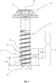
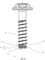
- Fig. 1 shows a side view of a screw 10 according to the invention, comprising a screw center axis M, a drive 12 and a thread-bearing shank 14.
- the direction along the screw center axis M is referred to below as the axial direction.
- the shank 14 carries at least one thread turn 16, which extends in a helix of constant pitch along the shank and thus forms a main thread 18 with a changing profile contour 20.
- the main thread 18 has a mean thread radius R M over its length.
- the mean thread radius R M is the average thread radius across the main thread 18 and will usually lie between the forming area radius and the supporting area radius.
- the mean thread radius R M will therefore approximately correspond to the nominal radius.
- the profile contour 20 is formed by the section of the thread in a section plane H of the helix in which the screw center axis M lies.
- the thread radius R is defined as the maximum orthogonal distance from the screw center axis M to the profile contour 20 of the thread pitch 16. This is Fig. 3a explained in more detail.
- the main thread 18 has a supporting area T and a forming area F, whereby in the forming area a forming profile contour 24 with a forming area radius R F is obtained and in the supporting area T a supporting profile contour 22 with a supporting area radius R T is obtained.
- the shaped profile contour 24 is formed by the projection of the thread 16 along the helix over an axially extending area with a length of three times the mean thread radius (3 x R M ). starting from the free end of the shaft 25 to a cutting plane of the helix H. This is defined in the Fig. 3c described in more detail.
- the projection therefore corresponds to the projection of the straight development of the thread onto the section plane H of the helix, which contains the screw center axis M.
- Fig. 2 shows the screw 10 in side view with the screw center axis M.
- the section plane H is shown, in which the screw center axis M lies.
- the Fig.3 b shows the front view of the development, which corresponds to a section plane of the helix.
- the projection onto the section plane results in the profile contour 24 according to Fig. 3c with a maximum extension that represents the effective form profile contour 24, which then creates the nut thread in the component.
- the forming area F ends at the forming area end FE, i.e. at the point of the main thread 18, at which the maximum extension of the forming profile contour 24 closest to the drive in the range of 85% of the mean thread radius in the radial direction outwards is still present, before the following profile contour in the range up to the end of L1, i.e. the corresponding length of the thread to the length 3 x R M in the axial direction, is again within the forming profile contour 24.
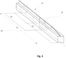
- the position of the forming area end FE is in Fig. 4 shown.
- the form profile contour 24, starting from the beginning of the thread is present for the last time before the profile contour, after a transition area, transitions into the support profile contour 22, which in the present example is maintained over the remaining screw length of the main thread 18.
- the transition area from the forming area F to the support area T is as short as possible.
- the transition area is shorter than L2 in the developed view and less than or equal to 2/3 x R M in the axial direction.
- the support area T has a length of at least L3 - L2 in the developed view, so that a basic holding function of the screw is fulfilled.
- the developed view of the part of the thread 16, which at least partially forms the support area is shown in Fig. 5a shown.
- Fig. 5b shows a front view of the development and Fig. 5c the corresponding projection of the development onto the section plane H of the helix, which defines the support profile contour 22.
- the front view and the projection are identical in this case, since the profile contour in the support area in this case consistently corresponds to the support profile contour 22.
- Fig. 6 It is shown that the support profile contour 22 and the shaped profile contour 24 are matched to one another in such a way that when the support profile contour 22 and the shaped profile contour 24 overlap, at least in the area E, which extends from 85% of the forming area radius R F in the radial direction outwards, the support profile contour 22 lies completely within the shaped profile contour 24.
- An enlargement of the area E is shown in Fig. 7
- the distance A1 between the flanks of the shaped profile contour 24 and the supporting profile contour 22 can be adjusted to the elasticity of the material, but is preferably between 0.03 mm and 0.05 mm, in particular 0.04 mm, for a screw with a nominal diameter of 5 mm. The distance preferably remains constant over the entire flank, at least in area E.
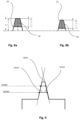
- Fig. 8a shows an enlargement of the area E of the shaped profile contour 24, which delimits a shaped profile surface 26, which is formed radially inwards, measured in a range of 10% of the shaped area radius, starting from the maximum orthogonal distance of the shaped profile contour to the screw center axis.
- Fig. 8b shows an enlargement of the area E of the support profile contour 22, wherein the support profile contour 22 delimits a support profile surface 28, which is in a range of 10% of the forming area radius R F starting from maximum orthogonal distance of the support profile contour, which corresponds to R T , to the screw center axis measured radially inwards.
- the shaped profile surface 26 is larger than the supporting profile surface 28. This has the advantage that even acute flank angles can be realized without excessively stressing the material into which the screw is screwed, and a high extraction force is achieved with a low screwing-in torque.
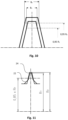
- the flank angle alpha of the form profile contour 24 is, as in Fig. 9 shown. It corresponds to 180° minus the sum of the base angles (beta 1, beta 2) of a trapezoid formed by the base sides of the trapezoid being formed by the intersection lines parallel to the screw axis at 85% of the profile radius RF and at 95% of the profile radius RF .
- Base angles are the angles on the longer base side of the trapezoid, i.e. at the intersection line at 85%.
- the flank angle is less than 35°, especially between 20° and 30°.
- Fig. 10 shows the comparison of the width B F of the shaped profile contour at 95% of the shape radius and the width of the supporting profile contour B T .
- the width B F of the shaped profile contour 24 is greater than the width B T of the supporting profile contour 22.
- the width B T of the support profile contour 22 is approximately 10% smaller than the width B F of the shaped profile contour 24.
- both the shaped profile contour 24 and the support profile contour 22 are symmetrical.
- the axis of symmetry is orthogonal to the screw center axis M, which intersects the profile contours 22 and 24 at half the width B T and B F , respectively.
- Fig. 11 shows a further embodiment of the thread in the supporting area T, wherein the transition from the thread flank to the thread root is flatter than in the previously described figures. Accordingly, the supporting profile contour 22 lies at least partially outside the forming area contour 24 in the area radially within 85% of the forming area radius.
- Fig. 12 shows a further embodiment of a screw according to the invention, wherein the shaft further comprises a thread 30 at the free end of the screw shaft.
- the thread comprises at least two thread turns 32, 34, which in their radius are at most 90% of the Form area radius R F and form an attachment area AB in which the attachment threads 32, 34 have the same radius profile over their associated helix and, in addition, the thread radius of the main thread is less than or equal to the thread radius of the attachment threads at the same axial distance from the free end 25 of the screw.
- the thread pitch 16 of the main thread 18 in the starting area has the same thread radius R as the starting thread 30, while maintaining the same axial distance from the free end of the screw.
- the starting thread pitches 32, 34 begin directly at the free end 25 of the screw shaft at the core. This ensures that ideal guidance of the screw is achieved immediately upon initial insertion.
- the starting thread 30 extends over approximately one turn, with the starting area ending at approximately one-third of a turn.
- the diameter of the free end of the screw shaft corresponds to at least 65% of twice the forming area radius R F .
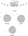
- the starting area is in the Figures 13a to 13d described in more detail.
- Fig. 13a shows an enlarged side view of the free end 25 of the screw shaft with three cross-sectional lines.
- the first cross-sectional line PP lies in the center of the attachment area AB.
- the cross-sectional line QQ lies at the end of the attachment area AB, and the cross-sectional line SS lies above the attachment area.
- Fig. 13b shows the cross section at the cross section line PP.
- all threads in the attachment area namely the two attachment threads 32, 34 and thread pitch 16 have the same thread radius.
- Fig. 13c at the end of the starting area, where all existing threads 16, 32, 34 still have the same thread radius R at the same axial distance from the free end of the screw axis.
- the cross-section along cross-section line SS illustrates the thread radii of the two locating threads 32, 34 and the thread pitch 16 of the main thread outside the locating area AB.
- the thread radii R of the locating threads 32, 34 are significantly smaller than the thread radius of the thread pitch 16 of the main thread 18 at this cross-section line.
- the locating threads taper off gently after the locating area, whereas the main thread pitch continues to grow until it reaches its profile contour.
- Fig. 14 shows a sectional view when creating a screw connection 40.
- the form profile contour 50 is in Fig. 15a
- the following thread with the support profile contour 58 in the support area of the screw is shown in Fig. 15b shown in the detailed view.
- the thread in the nut thread is shown in its spring-backed state with the contour line 56.
- the thread flanks of the support profile contour 58 are still spaced A2 from the spring-backed nut thread despite the spring-back of the nut thread. In this way, the thread of the support area can be screwed into the nut thread with almost no friction. Only when the screw 42 is finally tightened is the thread in the support area pressed against the flank of the nut thread, creating a force-locking connection in the direction of rotation.
Landscapes
- Engineering & Computer Science (AREA)
- General Engineering & Computer Science (AREA)
- Mechanical Engineering (AREA)
- Physics & Mathematics (AREA)
- Geometry (AREA)
- Wood Science & Technology (AREA)
- Chemical & Material Sciences (AREA)
- Dispersion Chemistry (AREA)
- Life Sciences & Earth Sciences (AREA)
- Surgical Instruments (AREA)
- Moulds For Moulding Plastics Or The Like (AREA)
- Injection Moulding Of Plastics Or The Like (AREA)
- Transmission Devices (AREA)
- Closures For Containers (AREA)
- Length-Measuring Instruments Using Mechanical Means (AREA)
- Dowels (AREA)
- Mutual Connection Of Rods And Tubes (AREA)
Description
Die Erfindung betrifft eine Schraube, insbesondere zur Verschraubung in Kunststoff, gemäß dem Oberbegriff des Anspruchs 1.The invention relates to a screw, in particular for screwing into plastic, according to the preamble of
Die
Diese Gestaltung hat den Nachteil, dass insbesondere bei der Verwendung der Schraube in Kunststoffen eine hohe Belastung des Bauteils erfolgt, wenn eine größere Steigung und ein geringerer Flankenwinkel verwirklicht werden sollen.This design has the disadvantage that, particularly when the screw is used in plastics, the component is subjected to high loads if a larger pitch and a smaller flank angle are to be achieved.
Eine ähnliche Schraube, insbesondere Betonschraube, wie in der
Die
Es ist Aufgabe der Erfindung, eine Schraube anzugeben, die bei geringem Einschraubmoment eine geringe mechanische Belastung des Bauteils erzielt und dabei hohe Auszugswerte realisieren kann.The object of the invention is to provide a screw which achieves low mechanical stress on the component with a low screwing-in torque and can thereby achieve high extraction values.
Die Aufgabe wird durch die kennzeichnenden Merkmale des Anspruchs 1 in Verbindung mit seinen Oberbegriffsmerkmalen gelöst.The problem is solved by the characterizing features of
Die Unteransprüche bilden vorteilhafte Weiterbildungen der Erfindung.The subclaims form advantageous developments of the invention.
In bekannter Weise weist eine Schraube eine Schraubenmittelachse, einen Antrieb und einen gewindetragenden Schaft auf. Der Schaft trägt wenigstens einen Gewindegang, der sich wenigstens bereichsweise in einer Helix konstanter Steigung entlang des Schafts erstreckt und so ein Hauptgewinde mit einer sich ändernden Profilkontur bildet, das über seine Länge einen mittleren Gewinderadius aufweist. Die Profilkontur ist durch den Schnitt des Gewindegangs in einer Schnittebene der Helix gebildet, wobei die Schraubenmittelachse in der Schnittebene liegt. Der Gewinderadius ist der maximale orthogonale Abstand von der Schraubenmittelachse zur Profilkontur des Gewindegangs. Das Hauptgewinde weist einen Tragbereich und einen Formbereich auf, wobei sich im Formbereich eine Formprofilkontur mit einem Formbereichsradius und im Tragbereich eine Tragprofilkontur mit einem Tragbereichsradius ergibt.In a known manner, a screw has a screw central axis, a drive and a thread-bearing shank. The shank carries at least one thread turn which extends at least partially along the shank in a helix of constant pitch, thus forming a main thread with a changing profile contour that has an average thread radius over its length. The profile contour is formed by the intersection of the thread turn in a sectional plane of the helix, with the screw central axis lying in the sectional plane. The thread radius is the maximum orthogonal distance from the screw central axis to the profile contour of the thread turn. The main thread has a load-bearing region and a forming region, with a forming profile contour with a forming region radius being produced in the forming region and a supporting profile contour with a supporting region radius being produced in the supporting region.
Die Formprofilkontur wird durch die Projektion des Gewindegangs entlang der Helix, insbesondere in Richtung des Antriebs über einen sich axial erstreckenden Bereich einer Länge von dreimal dem mittleren Gewinderadius ausgehend vom freien Ende des Schafts auf eine Schnittebene der Helix definiert, wobei die Schraubenmittelachse M in der Schnittebene liegt. Die Projektion entspricht also der Projektion der geradlinigen Abwicklung des Gewindegangs auf eine Schnittebene der Helix, in der die Schraubenmittelachse liegt. Dadurch ergibt sich eine Formprofilkontur mit einer maximalen Ausdehnung, die die wirksame Formprofilkontur abbildet. Diese Formprofilkontur weist einen maximalen orthogonalen Abstand zur Schraubenmittelachse auf, wodurch der Formbereichsradius definiert ist.The form profile contour is defined by the projection of the thread pitch along the helix, particularly in the direction of the drive, over an axially extending area with a length of three times the average thread radius, starting from the free end of the shaft, onto a sectional plane of the helix, with the screw center axis M lying in the sectional plane. The projection therefore corresponds to the projection of the rectilinear development of the thread pitch onto a sectional plane of the helix in which the screw center axis lies. This results in a form profile contour with a maximum extent that depicts the effective form profile contour. This form profile contour has a maximum orthogonal distance to the screw center axis, which defines the form area radius.
Der Formbereich endet an der Stelle der Helix, an der die dem Antrieb nächstliegende maximale Ausdehnung der Formprofilkontur im Bereich von 85% des mittleren Gewinderadius in Radialrichtung nach außen vorliegt, bevor die nachfolgenden Profilkonturen wieder innerhalb der Formprofilkontur liegen.The forming area ends at the point on the helix where the maximum extension of the forming profile contour closest to the drive is in the range of 85% of the mean thread radius in the radial direction outwards, before the subsequent profile contours are again within the forming profile contour.
Die Tragprofilkontur wird durch die Projektion des Gewindegangs auf eine Schnittebene der Helix entlang der Helix, insbesondere in Richtung des Antriebs, über einen sich axial erstreckenden Bereich gebildet, der bei einem Abstand von 2/3 des mittleren Gewinderadius zum Formbereichsende beginnt und bei 5/3 des mittleren Gewinderadius endet. Dieser Bereich bildet wenigstens einen Teilbereich des Tragbereichs. Dieser kann sich weiter entlang des Hauptgewindes in Richtung des Antriebs erstrecken, so lange die Profilkontur die Tragprofilkontur nicht überragt. Diese Tragprofilkontur weist einen maximalen orthogonalen Abstand zur Schraubenmittelachse auf, wodurch der Tragbereichsradius definiert ist.The support profile contour is formed by the projection of the thread pitch onto a section plane of the helix along the helix, particularly in the direction of the drive, over an axially extending area that begins at a distance of 2/3 of the mean thread radius to the end of the forming area and ends at 5/3 of the mean thread radius. This area forms at least a partial area of the Support area. This can extend further along the main thread in the direction of the drive, as long as the profile contour does not extend beyond the support profile contour. This support profile contour has a maximum orthogonal distance from the screw center axis, which defines the support area radius.
Auf diese Weise ist sichergestellt, dass ein möglichst kurzer Übergangsbereich vom Formbereich zum Tragbereich gewährleistet und ein ausreichend langer Tragbereich gegeben ist, sodass eine grundlegende Haltefunktion der Schraube erfüllt ist.In this way, it is ensured that the transition area from the forming area to the supporting area is as short as possible and that a sufficiently long supporting area is provided so that a basic holding function of the screw is fulfilled.
Ferner sind Tragprofilkontur und Formprofilkontur so aufeinander abgestimmt, dass bei einer Überlagerung der Tragprofilkontur und der Formprofilkontur entlang der Helix wenigstens in dem Bereich, der sich von 85% des Formbereichsradius in Radialrichtung nach außen erstreckt, die Tragprofilkontur vollständig innerhalb der Formprofilkontur liegt.Furthermore, the support profile contour and the form profile contour are coordinated in such a way that when the support profile contour and the form profile contour overlap along the helix, the support profile contour lies completely within the form profile contour at least in the area that extends from 85% of the form area radius in the radial direction outwards.
Dies sorgt dafür, dass einem Rückfedern des Materials im gefurchten Muttergewinde Rechnung getragen und ein geringes Eindrehmoment realisiert werden kann.This ensures that springback of the material in the grooved nut thread can be taken into account and a low screwing torque can be achieved.
Erfindungsgemäß ist vorgesehen, dass die Formprofilkontur eine Formprofilfläche begrenzt, die gemessen in einem Bereich von 10% des Formbereichsradius ausgehend vom maximalen orthogonalen Abstand der Formprofilkontur zur Schraubenmittelachse radial nach innen größer ist als eine durch die Tragprofilkontur begrenzte Tragprofilfläche, gemessen in einem Bereich von 10% des Formbereichsradius ausgehend vom maximalen orthogonalen Abstand der Tragprofilkontur zur Schraubenmittelachse radial nach innen.According to the invention, the shaped profile contour delimits a shaped profile surface which, measured in a range of 10% of the shaped area radius starting from the maximum orthogonal distance of the shaped profile contour to the screw center axis radially inwards, is larger than a supporting profile surface delimited by the supporting profile contour, measured in a range of 10% of the shaped area radius starting from the maximum orthogonal distance of the supporting profile contour to the screw center axis radially inwards.
Durch die erfindungsgemäße Profilkonturabstimmung kann der Ausgleich der Rückfederung im Muttergewinde auch bei relativ kleinen Flankenwinkeln realisiert werden, wobei eine ausreichende Flankenüberdeckung gewährleistet ist. Dabei wird eine Beschädigung des Bauteilmaterials, wie dies bei einer Schraube mit einem proportional vergrößerten Formbereichsgewinde eintritt, verhindert.The profile contour adjustment according to the invention allows springback compensation in the nut thread to be achieved even with relatively small flank angles, while ensuring sufficient flank overlap. This prevents damage to the component material, as occurs with a screw with a proportionally enlarged thread form area.
Bevorzugt weisen die Formprofilkontur und die Tragprofilkontur einen Flankenwinkel von weniger als 35° auf. Der Flankenwinkel der Formprofilkontur entspricht 180° abzüglich der Summe der beiden Basiswinkel eines Trapezes, das gebildet wird, indem die Grundseiten des Trapezes durch die zur Schraubenachse parallelen Schnittlinien bei 85% des Formprofilradius RF und bei 95% des Formprofilradius RF gebildet werden. Basiswinkel sind die Winkel an der längeren Grundseite des Trapezes, also bei der Schnittlinie bei 85%.Preferably, the shaped profile contour and the supporting profile contour have a flank angle of less than 35°. The flank angle of the shaped profile contour corresponds to 180° less the sum of the two base angles of a trapezoid formed by dividing the base sides of the trapezoid by the intersection lines parallel to the screw axis at 85% of the shaped profile radius R F and at 95% of the Form profile radius R F are formed. Base angles are the angles on the longer base side of the trapezoid, i.e. at the intersection line at 85%.
Die analoge Vorschrift zur Ermittlung des Flankenwinkels ergibt sich für die Tragprofilkontur, wobei hier die Schnittlinien bei 85% des Tragprofilradius RT und 95 % des Tragprofilradius RT gelegt werden.The analogous rule for determining the flank angle applies to the supporting profile contour, where the cutting lines are placed at 85% of the supporting profile radius R T and 95% of the supporting profile radius R T.
Der Flankenwinkel beträgt insbesondere zwischen 20° und 30°. Dies ist ein für Kunststoffverschraubung bewährter Flankenwinkel.The flank angle is typically between 20° and 30°. This is a proven flank angle for plastic screw connections.
Gemäß einer vorteilhaften Weiterbildung der Erfindung ist der Tragbereichsradius zwischen 1% bis 3% kleiner als der Formbereichsradius. Dies hat zur Folge, dass nur eine möglichst geringe Materialschädigung des Kunststoffbauteils eintritt, aber dennoch ein ausreichend großer Abstand zwischen Formprofilkontur und Tragprofilkontur, der die Materialrückfederung abbildet, eingestellt werden kann.According to an advantageous development of the invention, the support area radius is between 1% and 3% smaller than the forming area radius. This results in minimal material damage to the plastic component, while still allowing a sufficiently large distance between the forming profile contour and the support profile contour to accommodate the material springback.
Besonders vorteilhaft ist es, wenn die Tragprofilkontur bei 95% des Tragbereichsradius eine axiale Breite aufweist, die kleiner ist als die axiale Breite der Formprofilkontur bei 95% des Formbereichsradius. Dies ermöglicht eine einfache Gestaltung des Gewindeprofils, so dass die Formprofilfläche größer ist als die Tragprofilfläche.It is particularly advantageous if the support profile contour has an axial width at 95% of the support area radius that is smaller than the axial width of the formed profile contour at 95% of the formed area radius. This allows for a simple design of the thread profile so that the formed profile area is larger than the support profile area.
Insbesondere ist die Breite der Tragprofilkontur wenigstens 10%, insbesondere wenigstens 20% kleiner als die Breite der Formprofilkontur.In particular, the width of the support profile contour is at least 10%, in particular at least 20% smaller than the width of the shaped profile contour.
Zum Zweck einer einfacheren Herstellung können die Formprofilkontur und / oder die Tragprofilkontur symmetrisch sein.For the purpose of easier production, the shaped profile contour and/or the supporting profile contour can be symmetrical.
Gemäß einer besonders vorteilhaften Ausgestaltung ist der Formbereich kleiner als 2 x die Steigung. Bevorzugt wächst der Gewindegang bis zu seiner Formprofilkontur an und bleibt dann über einen Bereich bis zum Ende des Formbereichs konstant.According to a particularly advantageous embodiment, the forming area is less than 2 x the pitch. Preferably, the thread pitch increases up to its forming profile contour and then remains constant over a range up to the end of the forming area.
Bevorzugt kann das Verhältnis von Kernradius zu mittlerem Gewinderadius 0,6 bis 0,8 betragen. Dies sind für Kunststoffschrauben übliche Verhältnisse.Preferably, the ratio of core radius to mean thread radius is 0.6 to 0.8. These are typical ratios for plastic screws.
Ferner kann in einer Weiterbildung der Erfindung vorgesehen sein, dass in dem Bereich, der sich radial innerhalb von 85% des Formbereichsradius erstreckt, die Tragprofilkontur wenigstens teilweise außerhalb der Formprofilkontur liegt. Dadurch kann eine flexiblere Gestaltung des Flankenübergangs zum Gewindegrund ermöglicht werden, wodurch den Materialeigenschaften besser Rechnung getragen werden kann.Furthermore, in a further development of the invention, it can be provided that in the area extending radially within 85% of the forming area radius, the support profile contour lies at least partially outside the forming profile contour. This allows for a more flexible design of the flank transition to the thread root, which can better accommodate the material properties.
Weiter bevorzugt kann vorgesehen sein, dass der Kerndurchmesser im Formbereich kleiner oder gleich dem Kerndurchmesser im Tragbereich ist.It can further preferably be provided that the core diameter in the forming area is smaller than or equal to the core diameter in the supporting area.
Gemäß einer weiteren vorteilhaften Ausgestaltung der Erfindung kann der Schaft am freien Ende des Schraubenschaftes ein Ansetzgewinde aufweisen, wobei das Ansetzgewinde wenigstens zwei Ansetzgewindegänge umfasst, die in ihrem Radius höchstens 90% des Formbereichsradius erreichen und einen Ansetzbereich bilden.According to a further advantageous embodiment of the invention, the shaft can have a starting thread at the free end of the screw shaft, wherein the starting thread comprises at least two starting thread turns, the radius of which reaches at most 90% of the forming area radius and forms a starting area.
Der Ansetzgewindebereich wird dort gebildet, wo die Ansetzgewindegänge den gleichen Durchmesserverlauf aufweisen und zudem der Gewinderadius des Hauptgewindes kleiner oder gleich dem Gewinderadius der Ansetzgewindegänge ist.The attachment thread area is formed where the attachment threads have the same diameter profile and the thread radius of the main thread is less than or equal to the thread radius of the attachment threads.
Dies hat den Vorteil, dass die Schraube besonders gerade angesetzt werden kann, was zur Folge hat, dass das durch den nachfolgenden Formbereich im Kunststoffteil gefurchte Muttergewinde und das dem Formbereich nachfolgende Gewinde des Tragbereichs möglichst exakt ausgerichtet sind, so dass der Rückfederung des Kunststoffs genau Rechnung getragen werden kann. Auf diese Weise kann die Reibung des Tragbereichs während des Einschraubens weiter reduziert oder sogar verhindert werden.This has the advantage that the screw can be inserted particularly straight, resulting in the nut thread, which is grooved in the plastic part by the subsequent forming area, and the thread of the supporting area following the forming area being aligned as precisely as possible, allowing for the plastic's springback to be precisely accounted for. This further reduces or even eliminates friction in the supporting area during screwing in.
Bevorzugt ist vorgesehen, dass das Hauptgewinde im Ansetzbereich bei demselben axialen Abstand zum freien Ende des Schraubenschafts den gleichen Gewinderadius wie das Ansetzgewinde aufweist. Auf diese Weise werden durch die, insbesondere zwei, Ansetzgewindegänge und dem Hauptgewinde wenigstens drei gleiche Ansetzpunkte realisiert, die ein besonders gerades Ansetzen der Schraube ermöglichen.Preferably, the main thread in the attachment area has the same thread radius as the attachment thread, while maintaining the same axial distance from the free end of the screw shaft. In this way, at least three identical attachment points are realized by the attachment threads, in particular two, and the main thread, which enable particularly straight attachment of the screw.
Bevorzugt haben alle Gewindegänge im Ansetzbereich ihren Anfang in derselben Querschnittsebene. Ferner weisen alle Gewindegänge im Ansetzbereich die gleiche Querschnittskontur auf. Sie sind also gleichartig ausgebildet. So beginnen beispielsweise der Hauptgewindegang und die beiden Ansetzgewindegänge gleich und haben den gleichen Verlauf.Preferably, all threads in the attachment area begin in the same cross-sectional plane. Furthermore, all threads in the attachment area have the same cross-sectional contour. They are thus of similar design. For example, the main thread and the two attachment threads begin at the same point and follow the same path.
Alternativ können auch wenigstens drei Ansetzgewindegänge vorgesehen sein, wobei dann der Gewinderadius des Hauptgewindes im Ansetzbereich insbesondere kleiner als der Radius des Ansetzgewindes ist.Alternatively, at least three attachment threads can be provided, in which case the thread radius of the main thread in the attachment area is in particular smaller than the radius of the attachment thread.
Gemäß einer vorteilhaften Weiterbildung der Erfindung beginnen die Ansetzgewindegänge am Kern, wobei sich ausgehend vom Kern der Radius der Ansetzgewinde bis zum Ende des Ansetzbereichs stetig vergrößert. Dies sorgt für ein kontinuierliches und gleichmäßiges Ansetzen der Schraube.According to an advantageous development of the invention, the attachment threads begin at the core, with the radius of the attachment threads steadily increasing from the core to the end of the attachment area. This ensures continuous and even attachment of the screw.
Ferner können die Gewindegänge mit gleichem Gewinderadius auf gleicher axialer Höhe im Ansetzbereich umfänglich gleichverteilt sein. Auf diese Weise wird eine symmetrische Anlage am Vorloch des Kunststoffbauteils gewährleistet.Furthermore, the threads with the same thread radius can be evenly distributed around the circumference at the same axial height in the attachment area. This ensures symmetrical engagement with the pilot hole of the plastic component.
Insbesondere beträgt der Durchmesser des freien Endes der Schraube wenigstens 20%, insbesondere wenigstens 30%, insbesondere wenigstens 40%, insbesondere wenigstens 50%, insbesondere wenigstens 60% des doppelten Formbereichsradius. Eine solche stumpfe Spitze ist bei Kunststoffschrauben üblich.In particular, the diameter of the free end of the screw is at least 20%, in particular at least 30%, in particular at least 40%, in particular at least 50%, in particular at least 60% of twice the forming area radius. Such a blunt tip is common for plastic screws.
Das Ansetzgewinde kann unmittelbar ans freie Schraubenende anschließen. Dies sorgt dafür, dass mit dem ersten Ansetzen eine ideale Führung der Schraube erreicht ist.The starting thread can be directly connected to the free end of the screw. This ensures that the screw is perfectly guided from the first insertion.
Alternativ dazu kann das Ansetzgewinde beabstandet zum freien Schraubenende beginnen. Auf diese Weise kann der Bereich zum Schraubenende hin eine Suchfunktion erfüllen.Alternatively, the thread can begin at a distance from the free end of the screw. This allows the area toward the end of the screw to serve as a search function.
Zum Zwecke einer einfachen Herstellung können das Ansetzgewinde und das Hauptgewinde gewalzte Gewinde sein.For ease of manufacture, the starting thread and the main thread may be rolled threads.
Gemäß einer weiteren vorteilhaften Ausgestaltung können die Gewinde im Ansetzbereich einen stumpferen Flankenwinkel aufweisen als das Hauptgewinde außerhalb des Ansetzbereichs. Dies hat den Vorteil einer guten Zentrierung ohne einseitiges Einfurchen der Ansetzgewindegänge und erleichtert die Wiederholmontage.According to a further advantageous embodiment, the threads in the attachment area can have a more obtuse flank angle than the main thread outside the attachment area. This has the advantage of good centering without one-sided grooving of the attachment threads and facilitates repeat assembly.
Die Ansetzgewindegänge können am Ende des Ansetzbereichs abrupt auslaufen. Dies hat den Vorteil, dass beim weiteren Eindrehen der Schraube in ein enges Vorloch die Reibung minimiert ist.The threads can taper abruptly at the end of the starting area. This has the advantage of minimizing friction when further screwing the screw into a narrow pilot hole.
Das Ansetzgewinde kann sich gemäß einer weiteren vorteilhaften Weiterbildung höchstens über zwei Windungen erstrecken. Dies fördert eine effiziente Verschraubung, wobei dennoch eine optimale Ausrichtung der Schraube gewährleistet ist.According to a further advantageous development, the attachment thread can extend over a maximum of two turns. This promotes efficient screwing while still ensuring optimal alignment of the screw.
Es können in einem Gewindegang Unterbrechungen der Gewindegänge vorgesehen sein, wobei jedoch der interpolierte Verlauf des Gewinderadius gleichbleibt.Interruptions in the threads may be provided within a thread, but the interpolated course of the thread radius remains the same.
Gemäß einem weiteren Aspekt der Erfindung betrifft diese ein Verfahren zur Herstellung einer Schraubverbindung umfassend eine vorbeschriebene erfindungsgemäße Schraube. Die erfindungsgemäße Schraube wird dabei in ein Vorloch in ein Bauteil aus Kunststoff eingedreht, wobei im Formbereich ein Gegengewinde oder Muttergewinde mit der Formprofilkontur in den Kunststoff eingeformt wird. Das Gegengewinde federt, sobald es nicht mehr mit dem Formbereich in Eingriff steht im Tragbereich wieder zurück, so dass das Muttergewinde während des Einschraubvorgangs gerade nicht in Anlage mit dem Gewinde im Tragbereich kommt. Das Gewinde im Tragbereich wird erst mit dem endgültigen Anziehen der Schraube im Bauteil gegen das Gegengewinde gedrückt.According to a further aspect of the invention, this relates to a method for producing a screw connection comprising a screw according to the invention as described above. The screw according to the invention is screwed into a pilot hole in a plastic component, wherein a counter thread or nut thread with the shaped profile contour is formed into the plastic in the forming area. As soon as the counter thread is no longer engaged with the forming area, it springs back in the supporting area so that the nut thread does not come into contact with the thread in the supporting area during the screwing-in process. The thread in the supporting area is only pressed against the counter thread when the screw is finally tightened in the component.
Bevorzugt wird die erfindungsgemäße Schraube in ein Vorloch eingeschraubt, dessen Radius etwa 80% des Formbereichsradius entspricht.Preferably, the screw according to the invention is screwed into a pilot hole whose radius corresponds to approximately 80% of the mold area radius.
Ferner betrifft die Erfindung eine nach dem vorangehend beschriebenen Verfahren hergestellte Schraubverbindung.Furthermore, the invention relates to a screw connection produced according to the method described above.
Weitere Vorteile, Merkmale und Anwendungsmöglichkeiten der vorliegenden Erfindung ergeben sich aus der nachfolgenden Beschreibung in Verbindung mit den in den Zeichnungen dargestellten Ausführungsbeispielen.Further advantages, features and possible applications of the present invention will become apparent from the following description in conjunction with the embodiments shown in the drawings.
In der Zeichnung bedeutet:
- Fig. 1
- eine Seitenansicht einer erfindungsgemäßen Schraube;
- Fig. 2
- eine perspektivische Ansicht der Abwicklung des Gewindegangs;
- Fig. 3a
- eine perspektivische Ansicht der Abwicklung des Gewindegangs über 3 x RM;
- Fig. 3b
- eine Vorderansicht der Abwicklung des Gewindegangs;
- Fig. 3c
- die aus der Projektion des abgewickelten Gewindegangs erhaltene Formprofilkontur;
- Fig. 4
- eine perspektivische Ansicht des abgewickelten Gewindegangs mit Abbildung des Formbereichsendes;
- Fig. 5a
- eine perspektivische Ansicht des abgewickelten Gewindegangs im Tragbereich;
- Fig. 5b
- eine Vorderansicht des abgewickelten Gewindegangs;
- Fig. 5c
- eine sich durch Projektion ergebende Traggewindekontur;
- Fig. 6
- eine Überlagerung der Formgewindekontur aus
Fig. 3c und der Traggewindekontur ausFig. 5c - Fig. 7
- eine Vergrößerung der Überlagerung gemäß
Fig. 6 ; - Fig. 8a
- eine Darstellung der Formprofilfläche;
- Fig. 8b
- eine Darstellung der Tragprofilfläche;
- Fig. 9
- eine Darstellung des Formprofilflankenwinkels;
- Fig. 10
- eine Überlagerung einer Formprofilkontur und einer Tragprofilkontur;
- Fig. 11
- eine Überlagerung einer Formprofilkontur und einer Tragprofilkontur;
- Fig. 12
- eine Seitenansicht einer erfindungsgemäßen Schraube mit einem Ansetzgewinde;
- Fig. 13a
- eine Vergrößerung des Ansetzbereichs aus
Fig. 12 ; - Fig. 13b
- ein Querschnitt durch den Ansetzbereich;
- Fig. 13c
- ein weiterer Querschnitt durch den Ansetzbereich;
- Fig. 13d
- einen Querschnitt durch den Schraubenschaft außerhalb des Ansetzbereichs;
- Fig. 14
- eine Schnittansicht einer erfindungsgemäßen Schraubverbindung
- Fig. 15a
- eine Vergrößerung des Formgewindebereichs aus
Fig. 14 - Fig. 15b
- eine Vergrößerung des Traggewindebereichs aus
Fig. 14
- Fig. 1
- a side view of a screw according to the invention;
- Fig. 2
- a perspective view of the development of the thread;
- Fig. 3a
- a perspective view of the development of the thread over 3 x R M ;
- Fig. 3b
- a front view of the thread development;
- Fig. 3c
- the form profile contour obtained from the projection of the developed thread;
- Fig. 4
- a perspective view of the developed thread with an illustration of the end of the forming area;
- Fig. 5a
- a perspective view of the developed thread in the load-bearing area;
- Fig. 5b
- a front view of the unwound thread;
- Fig. 5c
- a supporting thread contour resulting from projection;
- Fig. 6
- an overlay of the form thread contour from
Fig. 3c and the supporting thread contourFig. 5c - Fig. 7
- an enlargement of the overlay according to
Fig. 6 ; - Fig. 8a
- a representation of the mold profile surface;
- Fig. 8b
- a representation of the supporting profile surface;
- Fig. 9
- a representation of the profile flank angle;
- Fig. 10
- an overlay of a form profile contour and a support profile contour;
- Fig. 11
- an overlay of a form profile contour and a support profile contour;
- Fig. 12
- a side view of a screw according to the invention with a starting thread;
- Fig. 13a
- an enlargement of the attachment area
Fig. 12 ; - Fig. 13b
- a cross-section through the attachment area;
- Fig. 13c
- another cross-section through the attachment area;
- Fig. 13d
- a cross-section through the screw shaft outside the application area;
- Fig. 14
- a sectional view of a screw connection according to the invention
- Fig. 15a
- an enlargement of the form thread area
Fig. 14 - Fig. 15b
- an enlargement of the supporting thread area
Fig. 14
Die Profilkontur 20 ist durch den Schnitt des Gewindegangs in einer Schnittebene H der Helix gebildet, in der die Schraubenmittelachse M liegt.The
Der Gewinderadius R ist als der maximale orthogonale Abstand von der Schraubenmittelachse M zur Profilkontur 20 des Gewindegangs 16 definiert. Dies ist in
Das Hauptgewinde 18 weist einen Tragbereich T und einen Formbereich F auf, wobei sich im Formbereich eine Formprofilkontur 24 mit einem Formbereichsradius RF und im Tragbereich T eine Tragprofilkontur 22 mit einem Tragbereichsradius RT ergibt.The
Die Formprofilkontur 24 wird durch die Projektion des Gewindegangs 16 entlang der Helix über einen sich axial erstreckenden Bereich einer Länge von dreimal dem mittleren Gewinderadius (3 x RM) ausgehend vom freien Ende des Schafts 25 auf eine Schnittebene der Helix H definiert. Diese ist in der
Die Projektion entspricht also der Projektion der geradlinigen Abwicklung des Gewindegangs auf die Schnittebene H der Helix, die die Schraubenmittelachse M beinhaltet.The projection therefore corresponds to the projection of the straight development of the thread onto the section plane H of the helix, which contains the screw center axis M.
Die perspektivische Darstellung der Abwicklung des Gewindegangs 16 ist in der
Die
Der Formbereich F endet am Formbereichsende FE, also an der Stelle des Hauptgewindes 18, an der die dem Antrieb nächstliegende maximale Ausdehnung der Formprofilkontur 24 im Bereich von 85% des mittleren Gewinderadius in Radialrichtung nach außen noch vorliegt, bevor die nachfolgende Profilkontur im Bereich bis zum Ende von L1, also der korrespondierenden Länge des Gewindegangs zur Länge 3 x RM in axialer Richtung wieder innerhalb der Formprofilkontur 24 liegt. Die Lage des Formbereichsendes FE ist in
Die Tragprofilkontur 22 wird durch die Projektion des Teils des Gewindegangs 16 auf eine Schnittebene H der Helix entlang der Helix über einen sich axial erstreckenden Bereich gebildet, der bei einem axialen Abstand von 2/3 des mittleren Gewinderadius RM zum Formbereichsende FE beginnt und bei einem axialen Abstand von 5/3 des mittleren Gewinderadius RM vom Formbereichsende FE endet. Dieser Bereich bildet wenigstens einen Teilbereich des Tragbereichs T. In
Indem der Bereich zur Ermittlung der Tragprofilkontur 22 bei 2/3 x RM beginnt, ist auf diese Weise sichergestellt, dass ein möglichst kurzer Übergangsbereich vom Formbereich F zum Tragbereich T gewährleistet ist. Somit ist der Übergangsbereich in der Abwicklung kürzer als L2 und in axialer Richtung kleiner oder gleich 2/3 x RM. Der Tragbereich T weist wenigstens eine Länge von L3 - L2 in der Abwicklung auf, sodass eine grundlegende Haltefunktion der Schraube erfüllt ist. Die Abwicklung des Teils des Gewindes 16, der den Tragbereich wenigstens teilweise bildet, ist in
In
Erfindungsgemäß ist die Formprofilfläche 26 größer als die Tragprofilfläche 28. Dies hat den Vorteil, dass auch spitze Flankenwinkel realisiert werden können, ohne dass das Material, in das die Schraube eingeschraubt wird, übermäßig beansprucht und dabei eine hohe Auszugskraft bei niedrigem Eindrehmoment erzielt wird.According to the invention, the shaped
Der Flankenwinkel alpha der Formprofilkontur 24 wird, wie in
Der Flankenwinkel beträgt weniger als 35°, insbesondere zwischen 20° und 30°.The flank angle is less than 35°, especially between 20° and 30°.
Die analoge Vorschrift zur Ermittlung des Flankenwinkels ergibt sich für die Tragprofilkontur 22, wobei hier die Schnittlinien bei 85% und 95% des Tragprofilradius RT gelegt werden.The analogous rule for determining the flank angle is obtained for the
Im vorliegenden Beispiel weist der Gewindegang 16 des Hauptgewindes 18 im Ansetzbereich bei gleichem axialen Abstand zum freien Ende der Schraube den gleichen Gewinderadius R auf wie das Ansetzgewinde 30. Die Ansetzgewindegänge 32, 34 beginnen unmittelbar am freien Ende 25 des Schraubenschaftes am Kern. Dies sorgt dafür, dass sofort mit dem ersten Ansetzen der Schraube eine ideale Führung der Schraube erreicht ist. Das Ansetzgewinde 30 erstreckt sich im vorliegenden Beispiel über etwa eine Windung, wobei der Ansetzbereich bei etwa einem Drittel einer Windung endet.In the present example, the
Der Durchmesser des freien Endes des Schraubenschaftes entspricht im vorliegenden Beispiel etwa wenigstens 65% des doppelten Formbereichsradius RF.In the present example, the diameter of the free end of the screw shaft corresponds to at least 65% of twice the forming area radius R F .
Der Ansetzbereich ist in den
Die Schraubverbindung 40 umfasst eine Schraube 42 und ein mit einem Vorloch 44 versehenes Kunststoffbauteil 46. Durch den vorderen Formbereich F der Schraube 42 wird ein Gewindegang im Kunststoffbauteil 46 vorgefurcht, in den dann der nachfolgende Tragbereich T des Gewindegangs eingreift. So ist ein Detail 1 in
Die Formprofilkontur 50 ist in
Claims (27)
- Screw (10) having a screw central axis (M), comprising a drive (12) and a threaded shank (14), having a thread (16) which extends in some regions at least in a helix of constant pitch along the shank and forms a main thread (18) which has an average thread radius (RM) that corresponds to the average thread radius over the entire length of the main thread (18), the thread radius (R) being the maximum orthogonal distance from the screw axis (M) to the profile contour (20) of the thread, the main thread (18) having a bearing area (T) and a forming area (F), wherein, in the forming area (F), there is a forming profile contour (24) having a forming area radius (RF) which corresponds to the maximum orthogonal distance of the forming profile contour (24) to the screw central axis, and in the bearing area (T), there is a bearing profile contour (22) having a bearing area radius (RT), wherein the forming profile contour (24) is defined by the projection of the thread turn along the helix over an axially extending area having a length of three times the mean thread radius (RM) starting from the free end (25) of the shank onto a section plane (H) of the helix, wherein the forming area (F) ends at a forming area end (FE), i.e. at the point of the helix where the forming profile contour (24) closest to the drive (12) in the area starting from 85% of the mean thread radius lies outwards in the radial direction, and the profile contour (20) following the end of the forming area (FE) lies again within the forming profile contour (24), the bearing profile contour (22) being defined by the projection of the thread turn along the helix onto a section plane (H) of the helix in an area which begins at an axial distance of 2/3 times the mean thread radius (RM) from the forming area end (FE) and ends at an axial distance of 5/3 times the mean thread radius (RM), and that, when the bearing profile contour (22) and the forming profile contour (24) overlap, at least in the area which extends radially outwards from 85% of the forming area radius (RF), lies completely within the forming profile contour (24), characterized in that a forming profile surface (26) which is delimited by the forming profile contour (24), measured within 10% of the forming area radius (RF) starting from the maximum orthogonal distance of the forming profile contour (24) to the screw central axis radially inwards, is larger than a bearing profile surface (28) which is delimited by the bearing profile contour (22), measured within 10% of the forming area radius (RF), starting from the maximum orthogonal distance of the bearing profile contour (22) from the screw central axis radially inwards.
- Screw according to claim 1, characterized in that the forming profile contour (24) and the bearing profile contour (22) have a flank angle (alpha) of less than 35°.
- Screw according to any one of claims 1 or 2 above, characterized in that the bearing area radius (RT) is smaller by between 1% and 3% than the forming area radius (RF).
- Screw according to any one of claims 1 to 3 above, characterized in that the bearing profile contour (22) has a width (BT) at 95% of the bearing area radius (RT) which is smaller than the width (BF) of the forming profile contour (24) at 95% of the forming area radius (RF).
- Screw according to claim 4, characterized in that the width (BT) of the bearing profile contour (22) is smaller by at least 10%, in particular by at least 20%, than the width (BF) of the forming profile contour (24).
- Screw according to any one of the preceding claims, characterized in that the forming profile contour (24) and/or the bearing profile contour (22) is/are symmetrical.
- Screw according to any one of the preceding claims, characterized in that the forming profile contour (24) does not increase further over a length of less than twice the pitch.
- Screw according to any one of the preceding claims, characterized in that the ratio of the core diameter to twice the mean thread radius (RM) is between 0.6 and 0.8.
- Screw according to any one of the preceding claims, characterized in that in the area which extends radially within 85% of the forming area radius (RF), the bearing profile contour (22) lies at least partially outside the forming profile contour (24).
- Screw according to any one of the preceding claims, characterized in that the core diameter in the forming area is smaller than or equal to the core diameter in the bearing area (T).
- Screw according to any one of the preceding claims, characterized in that the shank has a setting thread (30) in the area of the free end (25) of the screw shank, which setting thread (30) comprises at least two setting thread turns (32, 34), which in their radius reach at most 90% of the forming area radius (RF) and form a setting area (AB) in which the setting thread turns (32, 34) have the same radius profile and, moreover, in the setting area (AB), the thread radius of the main thread (18) is smaller than or equal to the thread radius of the setting thread turns (32, 34).
- Screw according to claim 11, characterized in that in the setting area (AB), the main thread (18) has the same thread radius (R) as the setting thread (32, 34).
- Screw according to claim 11, characterized in that at least three setting threads (32, 34) are provided, with the thread radius (R) of the main thread (18) in the setting area (AB) being smaller than that of the setting thread.
- Screw according to any one of claims 11 to 13 above, characterized in that the setting threads (32, 34) start at the core and increase continuously in their thread radius (R) in the direction of the bearing area (T).
- Screw according to any one of claims 11 to 14 above, characterized in that, in the setting area (AB), the thread turns (16, 32, 34) having the same thread radius (R) are evenly distributed around the circumference.
- Screw according to any one of claims 11 to 15 above, characterized in that the core diameter of the free end of the screw is at least 20%, or at least 30%, or at least 40%, or at least 50%, or at least 60% of twice the forming area radius.
- Screw according to any one of claims 11 to 16 above, characterized in that all the thread turns (16, 32, 34) in the setting area (AB) have their start in the same cross-sectional plane.
- Screw according to any one of claims 11 to 17 above, characterized in that all the threads (16, 32, 34) in the setting area (AB) have the same profile contour.
- Screw according to any one of claims 11 to 18 above, characterized in that the setting thread (30) directly adjoins the free shank end (25).
- Screw according to any one of claims 11 to 19 above, characterized in that the setting thread (30) starts at a distance from the free shank end (25).
- Screw according to any one of claims 11 to 19 above, characterized in that the setting thread (30) and the main thread (18) are rolled threads.
- Screw according to any one of claims 11 to 21 above, characterized in that the threads in the setting area (30) have a blunter flank angle in the contact area (30) than the main thread (18) outside the setting area (AB).
- Screw according to any one of claims 11 to 22 above, characterized in that the setting thread (30) runs out abruptly.
- Screw according to any one of claims 11 to 23 above, characterized in that the setting thread (30) extends over a maximum of two turns.
- Method of making a screw connection comprising a screw (10, 42) of the type specified in any one of claims 1 to 24 above, characterized in that the screw (42) is screwed into a pilot hole (44) in a plastic component (46), with a mating thread with the forming profile contour (50) being formed into the plastic in the forming area (F), whereupon the mating thread springs back again in the bearing area so that it does not come into contact with the thread in the bearing area (T) during the screwing-in process, and the thread in the bearing area (T) is only pressed against the mating thread when the screw is tightened in the component.
- Method according to claim 25, characterized in that the radius of the pilot hole corresponds to 80% of the forming area radius.
- Screw connection (40) comprising a screw (42) and a plastic component (46), which screw is manufactured using the method specified in claims 25 and/or 26 above.
Applications Claiming Priority (2)
| Application Number | Priority Date | Filing Date | Title |
|---|---|---|---|
| DE102018114984.0A DE102018114984A1 (en) | 2018-06-21 | 2018-06-21 | Screw for screwing in plastic |
| PCT/EP2019/066531 WO2019243606A1 (en) | 2018-06-21 | 2019-06-21 | Screw for screwing into plastic |
Publications (3)
| Publication Number | Publication Date |
|---|---|
| EP3810941A1 EP3810941A1 (en) | 2021-04-28 |
| EP3810941B1 true EP3810941B1 (en) | 2025-06-04 |
| EP3810941C0 EP3810941C0 (en) | 2025-06-04 |
Family
ID=67226212
Family Applications (1)
| Application Number | Title | Priority Date | Filing Date |
|---|---|---|---|
| EP19737668.4A Active EP3810941B1 (en) | 2018-06-21 | 2019-06-21 | Screw for screwing into plastic |
Country Status (15)
| Country | Link |
|---|---|
| US (1) | US12372111B2 (en) |
| EP (1) | EP3810941B1 (en) |
| JP (2) | JP7633024B2 (en) |
| CN (1) | CN112313418B (en) |
| CA (1) | CA3103053A1 (en) |
| DE (1) | DE102018114984A1 (en) |
| ES (1) | ES3037908T3 (en) |
| MX (1) | MX2020013341A (en) |
| MY (1) | MY208677A (en) |
| PH (1) | PH12020552201A1 (en) |
| PL (1) | PL3810941T3 (en) |
| SG (1) | SG11202012665XA (en) |
| TW (1) | TWI799603B (en) |
| WO (1) | WO2019243606A1 (en) |
| ZA (1) | ZA202007888B (en) |
Families Citing this family (2)
| Publication number | Priority date | Publication date | Assignee | Title |
|---|---|---|---|---|
| DE102018114984A1 (en) * | 2018-06-21 | 2019-12-24 | Ejot Gmbh & Co. Kg | Screw for screwing in plastic |
| CN216241731U (en) * | 2021-07-29 | 2022-04-08 | 浙江印天健康科技有限公司 | Fastening screw and lifting table using same |
Citations (1)
| Publication number | Priority date | Publication date | Assignee | Title |
|---|---|---|---|---|
| JP2002089525A (en) * | 2000-09-11 | 2002-03-27 | Shiga Fastener:Kk | Screw |
Family Cites Families (39)
| Publication number | Priority date | Publication date | Assignee | Title |
|---|---|---|---|---|
| US3426642A (en) * | 1962-02-05 | 1969-02-11 | Res Eng & Mfg | Self-tapping screws with threadforming projections |
| US3351115A (en) | 1965-11-22 | 1967-11-07 | Roger W Boehlow | Thread-forming and fastening screw |
| US3527136A (en) * | 1969-02-27 | 1970-09-08 | Standard Pressed Steel Co | Self-retained thread rolling screw |
| US3861269A (en) | 1971-01-04 | 1975-01-21 | Superior Dry Wall Screw Mfg Co | Fastener with improved thread construction |
| US3878759A (en) * | 1972-12-29 | 1975-04-22 | Textron Inc | Bi-lobular self-thread forming fastener |
| DE2543960A1 (en) * | 1975-10-02 | 1977-04-07 | Bosch Gmbh Robert | SELF-TAPPING FIXING SCREW |
| DE3411319C2 (en) | 1984-03-28 | 1986-12-04 | Boehringer Ingelheim KG, 6507 Ingelheim | Use of citric acid esters as blowing and / or nucleating agents for the production of thermoplastic plastic foams |
| JP2571805Y2 (en) * | 1991-05-30 | 1998-05-20 | 日東精工株式会社 | Tapping screw |
| JPH0741929Y2 (en) * | 1992-11-27 | 1995-09-27 | 若井産業株式会社 | Self drilling tapping screw |
| US5800107A (en) | 1996-04-19 | 1998-09-01 | Giannuzzi; Louis N. | Self-tapping, screw-type masonry anchor |
| US5795120A (en) | 1996-05-13 | 1998-08-18 | Hurdle; Donald R. | Reduced-friction thread forming or thread cutting screw |
| JPH1162933A (en) | 1997-08-22 | 1999-03-05 | Nitto Seiko Co Ltd | screw |
| JP3469846B2 (en) * | 1999-07-13 | 2003-11-25 | 株式会社メイドー | Guide boss grooved bolt |
| JP2001107932A (en) | 1999-10-13 | 2001-04-17 | Fukasawa:Kk | Screw |
| AUPQ919200A0 (en) | 2000-08-04 | 2000-08-24 | Hanstock Fasteners Pty Limited | Improvements relating to screws for concrete and masonry |
| DE10235817B4 (en) | 2002-08-05 | 2004-08-05 | Ejot Gmbh & Co. Kg | Self-tapping screw |
| JP4064950B2 (en) | 2004-07-09 | 2008-03-19 | 福井鋲螺株式会社 | Locking screw |
| JP4792850B2 (en) | 2005-07-15 | 2011-10-12 | 富士ゼロックス株式会社 | recoding media |
| RU2292491C1 (en) | 2005-08-10 | 2007-01-27 | Государственное образовательное учреждение высшего профессионального образования Волгоградский государственный технический университет (ВолгГТУ) | Self-locking screw |
| US7255523B2 (en) | 2005-12-22 | 2007-08-14 | Prime Source Building Products, Inc. | Dual threaded screw for composite materials |
| DE102006037006B4 (en) * | 2006-08-08 | 2014-08-07 | TOGE-Dübel A. Gerhard KG | Concrete screw |
| PL2176559T3 (en) * | 2007-08-13 | 2015-04-30 | Res Engineering&Manufacturing Inc | Thread forming fastener |
| JP5243906B2 (en) | 2007-09-28 | 2013-07-24 | 日東精工株式会社 | Threads in threaded parts |
| CN201461667U (en) | 2009-09-02 | 2010-05-12 | 赵恩 | Self-drilling fast screw |
| TW201137246A (en) * | 2010-04-16 | 2011-11-01 | Kwantex Res Inc | Wood screws |
| JP2012072840A (en) | 2010-09-29 | 2012-04-12 | Kitamura Seiko Kk | Wood screw |
| BR112013027513B1 (en) | 2011-04-28 | 2020-03-31 | Nitto Seiko Co., Ltd | SELF-TAPPING SCREW |
| US9523383B2 (en) * | 2013-03-26 | 2016-12-20 | Simpson Strong-Tie Company, Inc. | Variable thread fastener |
| US9404524B2 (en) | 2013-07-19 | 2016-08-02 | Conti Fasteners | High performance thread rolling screw/bolt for use in an unthreaded nut anchor |
| WO2015177930A1 (en) | 2014-05-23 | 2015-11-26 | 日産自動車株式会社 | Cooling circuit for internal combustion engine |
| US20170254352A1 (en) * | 2014-11-13 | 2017-09-07 | Essence Method Refine Co., Ltd. | Fastener |
| US9581183B2 (en) * | 2015-02-17 | 2017-02-28 | The Hillman Group, Inc. | Screw-type fastener |
| DE102015120470A1 (en) | 2015-11-26 | 2017-06-01 | Fischerwerke Gmbh & Co. Kg | concrete screw |
| DE102016103931A1 (en) * | 2016-03-04 | 2017-09-07 | Lisa Dräxlmaier GmbH | Screw for components made of foamed plastic |
| DE202016002905U1 (en) * | 2016-04-29 | 2017-08-02 | Arnold Umformtechnik Gmbh & Co. Kg | screw |
| TWI568939B (en) * | 2016-05-04 | 2017-02-01 | 徐國泰 | Screw |
| TWI623690B (en) * | 2017-01-25 | 2018-05-11 | Cement screw | |
| CA3095780C (en) * | 2018-04-09 | 2021-09-14 | The Hillman Group, Inc. | Screw-type fastener for concrete and hurricane resistance applications |
| DE102018114984A1 (en) * | 2018-06-21 | 2019-12-24 | Ejot Gmbh & Co. Kg | Screw for screwing in plastic |
-
2018
- 2018-06-21 DE DE102018114984.0A patent/DE102018114984A1/en active Pending
-
2019
- 2019-06-18 TW TW108121140A patent/TWI799603B/en active
- 2019-06-21 PL PL19737668.4T patent/PL3810941T3/en unknown
- 2019-06-21 MX MX2020013341A patent/MX2020013341A/en unknown
- 2019-06-21 EP EP19737668.4A patent/EP3810941B1/en active Active
- 2019-06-21 MY MYPI2020006762A patent/MY208677A/en unknown
- 2019-06-21 US US17/251,795 patent/US12372111B2/en active Active
- 2019-06-21 JP JP2020570951A patent/JP7633024B2/en active Active
- 2019-06-21 CN CN201980041366.4A patent/CN112313418B/en active Active
- 2019-06-21 WO PCT/EP2019/066531 patent/WO2019243606A1/en not_active Ceased
- 2019-06-21 CA CA3103053A patent/CA3103053A1/en active Pending
- 2019-06-21 ES ES19737668T patent/ES3037908T3/en active Active
- 2019-06-21 SG SG11202012665XA patent/SG11202012665XA/en unknown
-
2020
- 2020-12-17 PH PH12020552201A patent/PH12020552201A1/en unknown
- 2020-12-17 ZA ZA2020/07888A patent/ZA202007888B/en unknown
-
2024
- 2024-01-04 JP JP2024000253A patent/JP2024029181A/en active Pending
Patent Citations (1)
| Publication number | Priority date | Publication date | Assignee | Title |
|---|---|---|---|---|
| JP2002089525A (en) * | 2000-09-11 | 2002-03-27 | Shiga Fastener:Kk | Screw |
Also Published As
| Publication number | Publication date |
|---|---|
| CN112313418B (en) | 2023-03-28 |
| JP2024029181A (en) | 2024-03-05 |
| MX2020013341A (en) | 2021-02-02 |
| CA3103053A1 (en) | 2019-12-26 |
| US12372111B2 (en) | 2025-07-29 |
| PL3810941T3 (en) | 2025-09-08 |
| EP3810941A1 (en) | 2021-04-28 |
| KR20210021561A (en) | 2021-02-26 |
| SG11202012665XA (en) | 2021-01-28 |
| WO2019243606A1 (en) | 2019-12-26 |
| US20210364030A1 (en) | 2021-11-25 |
| JP7633024B2 (en) | 2025-02-19 |
| PH12020552201A1 (en) | 2021-06-28 |
| TWI799603B (en) | 2023-04-21 |
| EP3810941C0 (en) | 2025-06-04 |
| ES3037908T3 (en) | 2025-10-08 |
| DE102018114984A1 (en) | 2019-12-24 |
| TW202001110A (en) | 2020-01-01 |
| CN112313418A (en) | 2021-02-02 |
| MY208677A (en) | 2025-05-23 |
| JP2021527786A (en) | 2021-10-14 |
| BR112020025275A2 (en) | 2021-03-09 |
| ZA202007888B (en) | 2025-05-28 |
Similar Documents
| Publication | Publication Date | Title |
|---|---|---|
| DE4333791C2 (en) | Tapping screw | |
| DE2907360C2 (en) | Thread forming screw and blank for their manufacture | |
| EP3976977B1 (en) | Connecting element | |
| DE2917811A1 (en) | THREAD FORMING SCREW | |
| DE2461546A1 (en) | THREAD FORMING SCREW | |
| EP2483569A1 (en) | Moldable wire thread insert, method for the production thereof, component comprising moldable wire thread insert and a method for the production thereof | |
| EP3405686B1 (en) | Plastic thread element and connection assembly consisting of a plastic carrier part and a plastic thread part | |
| DE60317842T2 (en) | Fastener with multiple humped thread | |
| DE10003619A1 (en) | Nut unit for spherical screw drive has one-piece channel-like ball-conveying strip coil round inner circumferential surface of nut body and supported by support profile of support nut | |
| EP3810941B1 (en) | Screw for screwing into plastic | |
| DE3117624A1 (en) | Self-tapping multipurpose screw | |
| EP0504782A1 (en) | Screw, method and rolling die for manufacturing the same | |
| EP3810942B1 (en) | Self-tapping screw | |
| DE102009005336A1 (en) | Screw element, screw connection and method for producing a screw element | |
| EP3004665A1 (en) | Thread former and rolling die | |
| DE69715944T2 (en) | Process for the production of threaded bolts or threaded tie rods | |
| EP4069986B1 (en) | Bushing having a cleared thread portion for receiving a fastening element | |
| DE102008057552A1 (en) | Plastic component has bracket with plug hole, where ring-shaped anchoring ribs are provided at periphery of bracket, and retaining pins are inserted in plug hole | |
| EP2261517A1 (en) | Thread tapping screw | |
| EP4577749A1 (en) | Screw for direct screwing into a component | |
| WO2024042143A1 (en) | Screw for screwing directly into a component | |
| WO2017186838A1 (en) | Screw for cutting a thread | |
| DE102017103073A1 (en) | A tool for thread rolling a thread-forming screw, method for producing a hole-forming and / or thread-forming screw, and a thread-forming and / or hole-forming screw | |
| DE202024103005U1 (en) | Production-optimized threaded component | |
| DE102023110239A1 (en) | wood screw |
Legal Events
| Date | Code | Title | Description |
|---|---|---|---|
| STAA | Information on the status of an ep patent application or granted ep patent |
Free format text: STATUS: UNKNOWN |
|
| STAA | Information on the status of an ep patent application or granted ep patent |
Free format text: STATUS: THE INTERNATIONAL PUBLICATION HAS BEEN MADE |
|
| PUAI | Public reference made under article 153(3) epc to a published international application that has entered the european phase |
Free format text: ORIGINAL CODE: 0009012 |
|
| STAA | Information on the status of an ep patent application or granted ep patent |
Free format text: STATUS: REQUEST FOR EXAMINATION WAS MADE |
|
| 17P | Request for examination filed |
Effective date: 20210119 |
|
| AK | Designated contracting states |
Kind code of ref document: A1 Designated state(s): AL AT BE BG CH CY CZ DE DK EE ES FI FR GB GR HR HU IE IS IT LI LT LU LV MC MK MT NL NO PL PT RO RS SE SI SK SM TR |
|
| AX | Request for extension of the european patent |
Extension state: BA ME |
|
| RIN1 | Information on inventor provided before grant (corrected) |
Inventor name: ACHENBACH, MICHAEL Inventor name: BIRKELBACH, RALF Inventor name: DIECKMANN, VOLKER Inventor name: DRATSCHMIDT, FRANK Inventor name: HELLMIG, RALPH J. Inventor name: SELIMI, ILIR Inventor name: WEITZEL, STEPHAN Inventor name: HACKLER, JAN Inventor name: BEHLE, JUERGEN Inventor name: GERBER, RENE |
|
| DAV | Request for validation of the european patent (deleted) | ||
| DAX | Request for extension of the european patent (deleted) | ||
| STAA | Information on the status of an ep patent application or granted ep patent |
Free format text: STATUS: EXAMINATION IS IN PROGRESS |
|
| 17Q | First examination report despatched |
Effective date: 20230315 |
|
| RAP1 | Party data changed (applicant data changed or rights of an application transferred) |
Owner name: EJOT SE & CO. KG |
|
| GRAP | Despatch of communication of intention to grant a patent |
Free format text: ORIGINAL CODE: EPIDOSNIGR1 |
|
| STAA | Information on the status of an ep patent application or granted ep patent |
Free format text: STATUS: GRANT OF PATENT IS INTENDED |
|
| INTG | Intention to grant announced |
Effective date: 20240816 |
|
| GRAJ | Information related to disapproval of communication of intention to grant by the applicant or resumption of examination proceedings by the epo deleted |
Free format text: ORIGINAL CODE: EPIDOSDIGR1 |
|
| STAA | Information on the status of an ep patent application or granted ep patent |
Free format text: STATUS: EXAMINATION IS IN PROGRESS |
|
| GRAP | Despatch of communication of intention to grant a patent |
Free format text: ORIGINAL CODE: EPIDOSNIGR1 |
|
| STAA | Information on the status of an ep patent application or granted ep patent |
Free format text: STATUS: GRANT OF PATENT IS INTENDED |
|
| INTG | Intention to grant announced |
Effective date: 20250102 |
|
| GRAS | Grant fee paid |
Free format text: ORIGINAL CODE: EPIDOSNIGR3 |
|
| GRAA | (expected) grant |
Free format text: ORIGINAL CODE: 0009210 |
|
| STAA | Information on the status of an ep patent application or granted ep patent |
Free format text: STATUS: THE PATENT HAS BEEN GRANTED |
|
| AK | Designated contracting states |
Kind code of ref document: B1 Designated state(s): AL AT BE BG CH CY CZ DE DK EE ES FI FR GB GR HR HU IE IS IT LI LT LU LV MC MK MT NL NO PL PT RO RS SE SI SK SM TR |
|
| REG | Reference to a national code |
Ref country code: GB Ref legal event code: FG4D Free format text: NOT ENGLISH |
|
| REG | Reference to a national code |
Ref country code: CH Ref legal event code: EP |
|
| REG | Reference to a national code |
Ref country code: DE Ref legal event code: R096 Ref document number: 502019013410 Country of ref document: DE |
|
| REG | Reference to a national code |
Ref country code: IE Ref legal event code: FG4D Free format text: LANGUAGE OF EP DOCUMENT: GERMAN |
|
| U01 | Request for unitary effect filed |
Effective date: 20250606 |
|
| U07 | Unitary effect registered |
Designated state(s): AT BE BG DE DK EE FI FR IT LT LU LV MT NL PT RO SE SI Effective date: 20250702 |
|
| U20 | Renewal fee for the european patent with unitary effect paid |
Year of fee payment: 7 Effective date: 20250730 |
|
| REG | Reference to a national code |
Ref country code: ES Ref legal event code: FG2A Ref document number: 3037908 Country of ref document: ES Kind code of ref document: T3 Effective date: 20251008 |
|
| PGFP | Annual fee paid to national office [announced via postgrant information from national office to epo] |
Ref country code: ES Payment date: 20250829 Year of fee payment: 7 |
|
| PG25 | Lapsed in a contracting state [announced via postgrant information from national office to epo] |
Ref country code: NO Free format text: LAPSE BECAUSE OF FAILURE TO SUBMIT A TRANSLATION OF THE DESCRIPTION OR TO PAY THE FEE WITHIN THE PRESCRIBED TIME-LIMIT Effective date: 20250904 Ref country code: GR Free format text: LAPSE BECAUSE OF FAILURE TO SUBMIT A TRANSLATION OF THE DESCRIPTION OR TO PAY THE FEE WITHIN THE PRESCRIBED TIME-LIMIT Effective date: 20250905 |
|
| PGFP | Annual fee paid to national office [announced via postgrant information from national office to epo] |
Ref country code: PL Payment date: 20250725 Year of fee payment: 7 |
|
| PGFP | Annual fee paid to national office [announced via postgrant information from national office to epo] |
Ref country code: GB Payment date: 20250730 Year of fee payment: 7 |
|
| PG25 | Lapsed in a contracting state [announced via postgrant information from national office to epo] |
Ref country code: HR Free format text: LAPSE BECAUSE OF FAILURE TO SUBMIT A TRANSLATION OF THE DESCRIPTION OR TO PAY THE FEE WITHIN THE PRESCRIBED TIME-LIMIT Effective date: 20250604 |
|
| PGFP | Annual fee paid to national office [announced via postgrant information from national office to epo] |
Ref country code: CH Payment date: 20250828 Year of fee payment: 7 |
|
| PG25 | Lapsed in a contracting state [announced via postgrant information from national office to epo] |
Ref country code: RS Free format text: LAPSE BECAUSE OF FAILURE TO SUBMIT A TRANSLATION OF THE DESCRIPTION OR TO PAY THE FEE WITHIN THE PRESCRIBED TIME-LIMIT Effective date: 20250904 |
|
| PGFP | Annual fee paid to national office [announced via postgrant information from national office to epo] |
Ref country code: CZ Payment date: 20250722 Year of fee payment: 7 |