EP3810912B1 - Turboréacteur à transmission hybride - Google Patents
Turboréacteur à transmission hybride Download PDFInfo
- Publication number
- EP3810912B1 EP3810912B1 EP19731298.6A EP19731298A EP3810912B1 EP 3810912 B1 EP3810912 B1 EP 3810912B1 EP 19731298 A EP19731298 A EP 19731298A EP 3810912 B1 EP3810912 B1 EP 3810912B1
- Authority
- EP
- European Patent Office
- Prior art keywords
- rotation
- rotor
- electric motor
- turbojet engine
- integral
- Prior art date
- Legal status (The legal status is an assumption and is not a legal conclusion. Google has not performed a legal analysis and makes no representation as to the accuracy of the status listed.)
- Active
Links
Images


Classifications
-
- F—MECHANICAL ENGINEERING; LIGHTING; HEATING; WEAPONS; BLASTING
- F02—COMBUSTION ENGINES; HOT-GAS OR COMBUSTION-PRODUCT ENGINE PLANTS
- F02C—GAS-TURBINE PLANTS; AIR INTAKES FOR JET-PROPULSION PLANTS; CONTROLLING FUEL SUPPLY IN AIR-BREATHING JET-PROPULSION PLANTS
- F02C7/00—Features, components parts, details or accessories, not provided for in, or of interest apart form groups F02C1/00 - F02C6/00; Air intakes for jet-propulsion plants
- F02C7/36—Power transmission arrangements between the different shafts of the gas turbine plant, or between the gas-turbine plant and the power user
-
- F—MECHANICAL ENGINEERING; LIGHTING; HEATING; WEAPONS; BLASTING
- F01—MACHINES OR ENGINES IN GENERAL; ENGINE PLANTS IN GENERAL; STEAM ENGINES
- F01D—NON-POSITIVE DISPLACEMENT MACHINES OR ENGINES, e.g. STEAM TURBINES
- F01D15/00—Adaptations of machines or engines for special use; Combinations of engines with devices driven thereby
- F01D15/10—Adaptations for driving, or combinations with, electric generators
-
- F—MECHANICAL ENGINEERING; LIGHTING; HEATING; WEAPONS; BLASTING
- F02—COMBUSTION ENGINES; HOT-GAS OR COMBUSTION-PRODUCT ENGINE PLANTS
- F02C—GAS-TURBINE PLANTS; AIR INTAKES FOR JET-PROPULSION PLANTS; CONTROLLING FUEL SUPPLY IN AIR-BREATHING JET-PROPULSION PLANTS
- F02C3/00—Gas-turbine plants characterised by the use of combustion products as the working fluid
- F02C3/04—Gas-turbine plants characterised by the use of combustion products as the working fluid having a turbine driving a compressor
- F02C3/06—Gas-turbine plants characterised by the use of combustion products as the working fluid having a turbine driving a compressor the compressor comprising only axial stages
- F02C3/067—Gas-turbine plants characterised by the use of combustion products as the working fluid having a turbine driving a compressor the compressor comprising only axial stages having counter-rotating rotors
-
- H—ELECTRICITY
- H02—GENERATION; CONVERSION OR DISTRIBUTION OF ELECTRIC POWER
- H02K—DYNAMO-ELECTRIC MACHINES
- H02K7/00—Arrangements for handling mechanical energy structurally associated with dynamo-electric machines, e.g. structural association with mechanical driving motors or auxiliary dynamo-electric machines
- H02K7/10—Structural association with clutches, brakes, gears, pulleys or mechanical starters
- H02K7/116—Structural association with clutches, brakes, gears, pulleys or mechanical starters with gears
-
- H—ELECTRICITY
- H02—GENERATION; CONVERSION OR DISTRIBUTION OF ELECTRIC POWER
- H02K—DYNAMO-ELECTRIC MACHINES
- H02K7/00—Arrangements for handling mechanical energy structurally associated with dynamo-electric machines, e.g. structural association with mechanical driving motors or auxiliary dynamo-electric machines
- H02K7/18—Structural association of electric generators with mechanical driving motors, e.g. with turbines
- H02K7/1807—Rotary generators
- H02K7/1823—Rotary generators structurally associated with turbines or similar engines
-
- F—MECHANICAL ENGINEERING; LIGHTING; HEATING; WEAPONS; BLASTING
- F05—INDEXING SCHEMES RELATING TO ENGINES OR PUMPS IN VARIOUS SUBCLASSES OF CLASSES F01-F04
- F05D—INDEXING SCHEME FOR ASPECTS RELATING TO NON-POSITIVE-DISPLACEMENT MACHINES OR ENGINES, GAS-TURBINES OR JET-PROPULSION PLANTS
- F05D2220/00—Application
- F05D2220/30—Application in turbines
- F05D2220/32—Application in turbines in gas turbines
- F05D2220/323—Application in turbines in gas turbines for aircraft propulsion, e.g. jet engines
-
- F—MECHANICAL ENGINEERING; LIGHTING; HEATING; WEAPONS; BLASTING
- F05—INDEXING SCHEMES RELATING TO ENGINES OR PUMPS IN VARIOUS SUBCLASSES OF CLASSES F01-F04
- F05D—INDEXING SCHEME FOR ASPECTS RELATING TO NON-POSITIVE-DISPLACEMENT MACHINES OR ENGINES, GAS-TURBINES OR JET-PROPULSION PLANTS
- F05D2220/00—Application
- F05D2220/30—Application in turbines
- F05D2220/36—Application in turbines specially adapted for the fan of turbofan engines
-
- F—MECHANICAL ENGINEERING; LIGHTING; HEATING; WEAPONS; BLASTING
- F05—INDEXING SCHEMES RELATING TO ENGINES OR PUMPS IN VARIOUS SUBCLASSES OF CLASSES F01-F04
- F05D—INDEXING SCHEME FOR ASPECTS RELATING TO NON-POSITIVE-DISPLACEMENT MACHINES OR ENGINES, GAS-TURBINES OR JET-PROPULSION PLANTS
- F05D2220/00—Application
- F05D2220/70—Application in combination with
- F05D2220/76—Application in combination with an electrical generator
-
- F—MECHANICAL ENGINEERING; LIGHTING; HEATING; WEAPONS; BLASTING
- F05—INDEXING SCHEMES RELATING TO ENGINES OR PUMPS IN VARIOUS SUBCLASSES OF CLASSES F01-F04
- F05D—INDEXING SCHEME FOR ASPECTS RELATING TO NON-POSITIVE-DISPLACEMENT MACHINES OR ENGINES, GAS-TURBINES OR JET-PROPULSION PLANTS
- F05D2260/00—Function
- F05D2260/40—Transmission of power
- F05D2260/403—Transmission of power through the shape of the drive components
- F05D2260/4031—Transmission of power through the shape of the drive components as in toothed gearing
- F05D2260/40311—Transmission of power through the shape of the drive components as in toothed gearing of the epicyclical, planetary or differential type
Definitions
- the invention relates to the design of a turbomachine, in particular an aircraft turbojet or an aircraft turboprop with a fan driven by a reduction gear.
- the invention also relates to methods for implementing such a turbojet engine.
- the document US 2010/0326050 A1 describes a turbomachine with a counter-rotating rotor compressor.
- a transmission shaft drives the fan and the first rotor blades (denoted 17 on the figure 2 of the document quoted above).
- Pinions whose axes are fixed with respect to the casing ensure the transfer of rotational energy to second rotor blades (65) which rotate in the opposite direction to the first blades.
- An electric generator is provided, of which an inner rotor is integral with the first blades and an outer rotor is integral with the second blades, so as to produce an electric current resulting from the rotation of the transmission shaft.
- the reducer has an invariable reduction ratio.
- the design of such a turbomachine can therefore be improved in terms of energy consumption, type of energy that can be used and/or in its flexibility of use.
- the object of the invention is to propose a turbojet which consumes less fossil energy than the known turbojets. More precisely, the aim of the invention is to promote a flexible use of the energies which can power the turbojet and aims to optimize the use of these energies according to the conditions of use of the turbojet.
- a turbojet engine according to the prior art is also disclosed in the document US 2016/369702 A1 .
- the subject of the invention is an aircraft turbojet engine, comprising: an epicyclic gear train comprising an internal sun gear, a ring gear and a planet carrier; a turbine rotating a transmission shaft integral in rotation with the internal sun gear of the planetary gear; a fan attached to the crown of the planetary gear train; and an electric machine comprising a rotor and a stator, the rotor being secured to the planet carrier of the epicyclic gear train, and the axis of rotation of the rotor of the electric motor being coincident with the axis of rotation of the transmission shaft.
- the invention also relates to an aircraft turbojet engine, comprising: an epicyclic gear train comprising an internal sun gear, a ring gear and a planet carrier; a turbine driving in rotation a transmission shaft integral in rotation with the internal sun gear of the epicyclic gear train; a fan integral with the planet carrier of the planetary gear train; and an electric machine comprising a rotor and a stator, the rotor being secured to the ring gear of the planetary gear train, and the axis of rotation of the rotor of the electric motor coinciding with the axis of rotation of the transmission shaft.
- the invention also relates to methods for operating the turbojet engine. These different uses of the same system illustrate different advantageous aspects of the turbojet engine according to the invention.
- the turbojet engine of the invention offers innumerable possibilities for driving the fan.
- a significant gradient in the speed of the fan can take a long time, in particular because of the inertia of the rotating assembly.
- the turbojet according to the invention makes it possible, when the electric motor is controlled appropriately, to overcome this inertia and therefore to make the controls of the device more direct.
- the turbojet engine according to the invention therefore makes it possible to potentially improve the safety of the aircraft.
- the terms “internal” (or “inner”) and “external” (or “outer”) refer to a positioning relative to the axis of rotation of the turbojet engine.
- the axial direction corresponds to the direction along the axis of rotation of the turbojet engine.
- the radial direction is perpendicular to the axis of rotation. Upstream and downstream refer to the main flow direction of the stream in the turbojet engine.
- integral is understood as integral in rotation, and in particular rigidly linked.
- the expression “the compressor is rotating” or any equivalent expression means that the rotor of such a compressor is in rotational motion.
- the speed of rotation of the electric motor denotes by abuse of language the speed of rotation of the rotor of the electric motor.
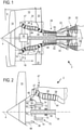
- the figure 1 represents a double-flow turbojet engine 2.
- the turbojet engine 2 has an axis of rotation 4 which can also form an axis of axial symmetry.
- the turbojet engine 2 has an annular inlet 6 dividing into a primary stream 8 and into a secondary stream 10 thanks to a separation nozzle 12 of circular shape.
- These veins 8 and 10 are borrowed by, respectively, a primary flow 14 and a secondary flow 16, which meet at the outlet of the turbojet engine.
- the primary 14 and secondary 16 streams are coaxial annular streams fitted into one another.
- the secondary flow 16 is accelerated by a fan 18, in particular placed at the inlet 6, so that a thrust reaction can be generated. This can be used for the flight of an aircraft.
- Diffuser blades 20 may be disposed in secondary stream 10 and configured to increase the axial component of secondary flow velocity.
- the fan can be arranged upstream of the primary stream 8 and the secondary stream 10, in particular at an axial distance from these streams.
- the fan can be of the non-ducted type, for example with double counter-rotating rotors. It can be placed around the primary vein.
- the turbojet engine 2 comprises a compression zone, a combustion chamber 22 and a primary flow expansion zone 14.
- the compression zone is formed by two compressors, including an upstream compressor 24 and a downstream compressor 26.
- the downstream compressor 26, also called high-pressure compressor, can be placed at the inlet of the combustion chamber 22.
- the turbojet engine 2 may have a high-pressure turbine 28 coupled to a high-pressure shaft 30, then a low-pressure turbine 32 coupled to a low-pressure shaft 34.
- the shafts 30, 34 can rotate at different speeds from each other and be fitted into each other.
- These turbines 28, 32 can form the primary flow expansion zone 14.
- the rotors of the compressors 24, 26 can be fixed to the respective shafts 30, 34 via flanges or discs.
- the mechanical power received from the turbines 28, 32 is transmitted via the shafts 30, 34 so as to set the compressors 24, 26 in motion. stator.
- the rotation of the rotors around their axis of rotation 4 thus makes it possible to generate a flow of air and to compress the latter progressively up to the inlet of the combustion chamber 22.
- the fan 18 is driven in rotation by the intermediary reduction means, such as a reduction gear 36 with an epicyclic gear train which will be described in more detail below.
- the low-pressure compressor 24 comprises stator vanes 39 and rotor vanes 40 inserted between the stator vanes 39.
- the compressor 24 can optionally end with two successive rows of stator vanes 39.
- At least one of the stator rows 39 is replaced by a row of counter-rotating rotor blades, that is to say with a direction of rotation opposite to the blades 40.
- the rotor blades 40 can be supported by a rotor 44 which can be integral with the shaft 34.
- the stator of the turbojet engine 2 may comprise several support casings, including an upstream casing 47 and a downstream casing 49 arranged on either side of the low-pressure compressor 24, also called the intermediate casing.
- These casings 47, 49 may comprise annular sleeves forming axial sections of the primary stream 8. They may have substantially radial support arms (called "struts") 46, 48 radially crossing the stream 8.
- the annular sleeves may have gooseneck profiles. They can mark reductions in diameter of the primary vein 8, as does its gradual convergence.
- the upstream casing 47 and its arms 46 can support the reducer 36. It can also support one or more bearings to support in rotation the fan 18, the shaft 34, or rotating parts of the reducer 36.
- the high-pressure compressor 26 Downstream of the arms 48 is the high-pressure compressor 26 provided with stator 50 and rotor 52 vanes. The latter being driven in rotation by means of the shaft 30.
- the rotor vanes of the high compressor -pressure 26 can be driven by the shaft 34 or the rotor of the low-pressure compressor 28, possibly via a reducer.
- the picture 2 illustrates an enlarged part of the turbojet engine 2 of the figure 1 , with a focus on the reducer 36, in a first embodiment.
- the reducer 36 comprises an internal sun gear 60 integral with the transmission shaft 34. Satellites 62 of which only one is visible on the section of the figure 2 mesh with the inner sun gear 60. The satellites 62 can have a double rotational movement, around their axes 64 and around the axis 4. By abuse of language, we will speak in the present application of the axis 64 to designate both the geometric axis of aximetry of a satellite 62 and the physical axis or pion around which the satellite 62 rotates.
- a crown 66 (also called outer planetary) meshes with the satellites 62.
- the fan 18 is secured to the crown 66.
- the axes 64 are assembled to a planet carrier ring 68.
- the planet carrier 68 rotates on itself around the axis 4.
- An electric motor 70 is provided to provide or recover electrical energy to/from the movement of the planet carrier 68.
- the latter is secured to the rotor 72 of the electric motor 70 while the stator 74 of the electric motor 70 is fixed relative to the casing 47.
- the train 36 behaves like a single gear and the fan 18 rotates at a slower speed than the shaft 34, with a fixed speed ratio dictated by the ratio of the diameters of the elements of the train 36.
- the motor 70 is not powered, the rotor 72, driven by the planet carrier 68, rotates and the motor 70 generates an electric current.
- Suitable bearings 80, 90 can support the shaft 34 and the crown 66 in rotation.
- the housing 47 via an adapted design of flanges, makes it possible to contain these bearings 80, 90.
- the picture 3 represents a turbojet engine 102 according to a second embodiment of the invention. Only items that are different from the embodiment of the figure 2 are incremented by 100.
- the planetary gear 136 is composed of an inner sun gear 60, satellites 62 having axes 64, a planet carrier 168 and a crown 166.
- the rotor 72 is integral with the crown 166 and the fan 18 is integral with the planet carrier 168.
- the motor 70 is coaxial with the axis 4. It is however possible, depending on the size at the heart of the turbojet, to offset the rotor and therefore to connect the planet carrier 68 or the ring gear 166 to the rotor 72 by means of a belt or a gear.
- certain vanes of the compressor 24, in particular the counter-rotating stator vanes can be integral with the rotor 72.
- the figure 4 represents a part of the turbojet engine 202, in a third embodiment, which can be combined with the other embodiments.
- a planetary gear train 236 connects a transmission shaft 230 driven by the turbine 28 to a secondary transmission shaft 230' which drives the fan.
- the secondary shaft 230' can play the role of the shaft noted 34 on the figure 2 and 3 , directly, or indirectly, via a suitable reducer.
- the low-pressure compressor 24 is driven by the secondary shaft 230 'while the high-pressure compressor 26 is driven by the shaft 230.
- An electric motor 270 can be provided so that its rotor 272 is integral with the planet carrier 268 of the train 236. According to an operation equivalent to that of the trains 36 or 136, the electric motor 270 makes it possible to continuously regulate the speed reduction ratio between the compressors 24, 26 or to recover kinetic energy.
- the rotor 272 of the electric motor 270 can alternatively be integral with the ring gear 266 of the train 236.
- the shaft 34 integral with the turbine 32 passes through the train 236 so as to drive the low-pressure compressor 24 and the ring gear of the train 236.
- the inner sun gear 260 is fitted around and rotates freely around the shaft 34, to drive the high-pressure compressor 26.
- An electric motor can be integral with the planet gear carrier 236.
- the motor can be integral with the ring gear of the gear 236 and the shaft 34 can drive the planet carrier of train 236.
- one of the compressors 24, 26 can be driven by the planet carrier.
- the rotors of the compressors can rotate in opposite directions.
- an epicyclic gear train and optionally an electric motor is/are provided between the two transmission shafts 30, 34 of the turbines 28, 32.
- the figure 5 schematically describes the impact of the presence of the electric motor on the speed of the fan 18.
- a set point value 300 is given by a user for the desired speed or torque of the fan.
- a value 310 of the speed or torque of the shaft 34, 230' is measured at the same instant.
- a calculation 320 is carried out which dictates the speed or the torque 330 of the rotor 72 of the electric motor 70 that must be targeted to obtain the setpoint value 300, from the measured value 310.
- graph A illustrates the setpoint which is a constant value, at least on the time scale in question here.
- Turbine speed/torque increases smoothly over time as shown in curve B, induced by increasing throttle and compression.
- This curve B also illustrates the speed/torque of the blower, in the absence of the electric motor.
- Curve C is the actual blower speed/torque obtained by the action of the electric motor.
- the measurement of the speed/torque, and the control of the electric motor is done at any time to change the value 330 according to the progressive changes of the value 310.
- the value 330 therefore changes according to the curve B towards a stationary value.
Landscapes
- Engineering & Computer Science (AREA)
- Chemical & Material Sciences (AREA)
- Combustion & Propulsion (AREA)
- Mechanical Engineering (AREA)
- General Engineering & Computer Science (AREA)
- Power Engineering (AREA)
- Structures Of Non-Positive Displacement Pumps (AREA)
- Retarders (AREA)
Description
- L'invention concerne la conception d'une turbomachine, notamment un turboréacteur d'avion ou un turbopropulseur d'aéronef avec une soufflante entraînée par un réducteur. L'invention a également trait à des procédés de mise en œuvre d'un tel turboréacteur.
- Le document
US 2010/0326050 A1 décrit une turbomachine avec un compresseur à rotors contrarotatifs. Un arbre de transmission entraîne la soufflante et des premières aubes rotoriques (notées 17 sur lafigure 2 du document cité ci-dessus). Des pignons dont les axes sont fixes par rapport au carter assurent le transfert de l'énergie de rotation à des deuxièmes aubes rotoriques (65) qui tournent en sens opposé aux premières aubes. Une génératrice électrique est prévue, dont un rotor interne est solidaire des premières aubes et un rotor externe est solidaire des deuxièmes aubes, de sorte à produire un courant électrique résultant de la rotation de l'arbre de transmission. - Si cette conception permet de transformer une énergie mécanique en énergie électrique, il n'est pas possible de réinjecter l'énergie électrique dans l'énergie mécanique nécessaire au vol de l'avion. Ainsi, les pignons ayant des axes fixes, le réducteur a un rapport de réduction invariable. La conception d'une telle turbomachine est donc perfectible en termes de consommation d'énergie, de type d'énergie utilisable et/ou dans sa flexibilité d'utilisation.
- L'invention a pour objectif de proposer un turboréacteur qui consomme moins d'énergie fossile que les turboréacteurs connus. Plus précisément, l'invention a pour objectif de favoriser une utilisation flexible des énergies qui peuvent alimenter le turboréacteur et vise à optimiser l'utilisation de ces énergies en fonction des conditions d'emploi du turboréacteur. Un turboréacteur selon l'art antérieur est également divulgué dans le document
US 2016/369702 A1 . - L'invention a pour objet un turboréacteur d'aéronef, comprenant : un train épicycloïdal comprenant un planétaire interne, une couronne et un porte-satellite ; une turbine entraînant en rotation un arbre de transmission solidaire en rotation avec le planétaire interne du train épicycloïdal ; une soufflante solidaire de la couronne du train épicycloïdal ; et une machine électrique comprenant un rotor et un stator, le rotor étant solidaire du porte-satellite du train épicycloïdal, et l'axe de rotation du rotor du moteur électrique étant confondu à l'axe de rotation de l'arbre de transmission.
- Alternativement, l'invention a également pour objet un turboréacteur d'aéronef, comprenant : un train épicycloïdal comprenant un planétaire interne, une couronne et un porte-satellite ; une turbine entraînant en rotation un arbre de transmission solidaire en rotation avec le planétaire interne du train épicycloïdal ; une soufflante solidaire du porte-satellite du train épicycloïdal ; et une machine électrique comprenant un rotor et un stator, le rotor étant solidaire de la couronne du train épicycloïdal, et l'axe de rotation du rotor du moteur électrique étant confondu à l'axe de rotation de l'arbre de transmission.
- Selon des modes avantageux de l'invention, le turboréacteur peut comprendre une ou plusieurs des caractéristiques suivantes:
- des moyens de variation de la vitesse et du sens de rotation du rotor du moteur électrique. Ces moyens peuvent comprendre des circuits électriques tels des redresseurs, variateurs, inverseurs, etc. Ces moyens peuvent également être mécaniques, tel un variateur à courroie, un pignon de sortie d'arbre moteur, etc. ;
- un compresseur basse-pression et un compresseur haute-pression, le compresseur basse-pression étant entraîné en rotation directement par l'arbre de transmission et le compresseur haute-pression étant entraîné en rotation par l'arbre de transmission via un train d'engrenage ;
- le train d'engrenage est tel que les rotors des compresseurs tournent dans des sens opposés l'un de l'autre ;
- chaque compresseur inclut un redresseur en aval d'une rangée annulaire d'aubes rotoriques, le redresseur pouvant être fait d'aubes tournant en sens opposé des aubes rotoriques ;
- au moins un compresseur muni d'aubes rotoriques contrarotatives, au moins une rangée d'aubes rotoriques étant entraînées par l'arbre de transmission et au moins une rangée d'aubes rotoriques étant entraînées en direction opposée par le moteur électrique ;
- le stator du moteur électrique est solidaire du carter du turboréacteur ;
- des moyens mécaniques sont prévus pour solidariser le rotor et le stator du moteur électrique, notamment un embrayage frein. Alternativement, des doigts électromagnétiques peuvent venir s'interposer dans des logements prévus à cet effet ;
- une turbine basse-pression et une turbine haute-pression, l'arbre de transmission solidaire du planétaire intérieur étant entraîné par la turbine basse-pression.
- L'invention a également trait à des procédés de mise en œuvre du turboréacteur. Ces différentes utilisations d'un même système illustrent différents aspects avantageux du turboréacteur selon l'invention.
- Ainsi, la mise en œuvre du turboréacteur selon l'invention peut comprendre :
- une étape de récupération d'énergie cinétique lors de laquelle le moteur électrique est utilisé en générateur. En effet, le moteur électrique et les moyens électroniques de contrôle associés permettent au moteur électrique de fonctionner en générateur et donc de délivrer de l'énergie électrique à des batteries ou à des instruments ou appareils à bord de l'avion ;
- une étape de régulation de la vitesse et du sens de rotation du moteur électrique afin d'obtenir, à partir d'une vitesse mesurée de rotation de l'arbre de transmission, une vitesse de rotation de consigne de la soufflante. Une boucle de rétroaction permet d'obtenir la vitesse souhaitée pour la soufflante (responsable à environ 80% de la poussée d'un aéronef) quelque soit la vitesse de l'arbre de transmission.
- une étape de régulation du couple délivré par le moteur électrique afin d'obtenir, à partir d'un couple mesuré de l'arbre de transmission, un couple de consigne de la soufflante. De la même manière que pour la vitesse, le moteur électrique peut être contrôlé en couple. Un couple peut être considéré comme négatif lorsque le moteur fonctionne en générateur ;
- une étape de blocage mécanique du moteur électrique. Par des moyens de préférence mécanique, le moteur électrique peut être bloqué. En d'autres termes, son rotor est maintenu fixe et solidaire du stator. Ceci a pour conséquence de faire fonctionner le train épicycloïdal comme un réducteur simple. Selon que la soufflante soit solidaire des axes des satellites ou de la couronne, la soufflante tournera en sens inverse ou dans le même sens que l'arbre de transmission ;
- une étape de maintenance lors de laquelle la soufflante est maintenue fixe et la turbine est entraînée en rotation par le moteur électrique. « Maintenance » est à comprendre au sens large et incluant une inspection, des tests, un montage/démontage de certains ensembles du turboréacteur, etc. Il peut par exemple être nécessaire de vérifier que la rotation de la turbine se fait sans encombre et donc l'entraîner directement par le moteur électrique est possible lorsque la soufflante est maintenue fixe. Le maintien de la soufflante peut être effectué manuellement ou à l'aide d'un outil d'atelier dédié à cet effet comme par exemple un structure mécano-soudée attachée aux aubes et fixée à un bâti fixe de l'atelier ;
- une étape de roulage au sol effectuée grâce à la rotation de la soufflante uniquement entraînée par le moteur électrique. L'arbre de transmission ou la turbine est équipé d'un frein, par exemple électromécanique, pouvant être actionné pour maintenir l'arbre et la turbine fixe lors d'un tel roulage au sol. Ceci permet d'éviter la pollution due à l'utilisation de carburant sur le tarmac.
- Le turboréacteur de l'invention offre d'innombrables possibilités d'entraînement de la soufflante. En particulier, lors de certaines manœuvres en vol, il peut être nécessaire de rapidement faire évoluer la vitesse de la soufflante. Un gradient important de la vitesse de la soufflante peut prendre beaucoup de temps notamment à cause de l'inertie de l'ensemble tournant. Le turboréacteur selon l'invention permet, lorsque le moteur électrique est commandé de façon appropriée, de pallier cette inertie et donc de rendre les commandes de l'appareil plus directes.
- Outre les avantages sur la consommation en énergie fossile, le turboréacteur selon l'invention permet donc d'améliorer potentiellement la sécurité de l'avion.
-
- La
figure 1 représente un turboréacteur selon l'invention ; - La
figure 2 représente une partie du turboréacteur selon un premier mode de réalisation l'invention ; - La
figure 3 représente une partie de turboréacteur selon un deuxième mode de réalisation l'invention ; - La
figure 4 illustre une partie de turboréacteur selon un troisième mode de réalisation l'invention ; - La
figure 5 représente un procédé selon l'invention. - Dans la description qui va suivre, les termes « interne » (ou « intérieur ») et « externe » (ou « extérieur ») renvoient à un positionnement par rapport à l'axe de rotation du turboréacteur. La direction axiale correspond à la direction le long de l'axe de rotation du turboréacteur. La direction radiale est perpendiculaire à l'axe de rotation. L'amont et l'aval sont en référence au sens d'écoulement principal du flux dans le turboréacteur. Le terme « solidaire » est compris comme solidaire en rotation, et notamment rigidement lié.
- Par abus de langage, l'expression le « compresseur tourne » ou toute expression équivalente signifie que le rotor d'un tel compresseur est en mouvement de rotation. De même, la vitesse de rotation du moteur électrique désigne par abus de langage la vitesse de rotation du rotor du moteur électrique.
- Les figures représentent les éléments de manière schématique, notamment sans les éléments d'assemblage ou d'étanchéité.
- La
figure 1 représente un turboréacteur 2 double-flux. - Le turboréacteur 2 présente un axe de rotation 4 pouvant également former un axe de symétrie axiale. Le turboréacteur 2 présente une entrée annulaire 6 se divisant en une veine primaire 8 et en une veine secondaire 10 grâce à un bec de séparation 12 de forme circulaire. Ces veines 8 et 10 sont empruntées par, respectivement, un flux primaire 14 et un flux secondaire 16, qui se rejoignent en sortie du turboréacteur. Les flux primaire 14 et secondaire 16 sont des flux annulaires coaxiaux et emmanchés l'un dans l'autre.
- Le flux secondaire 16 est accéléré par une soufflante 18, notamment disposée en entrée 6, si bien qu'une réaction de poussée peut être générée. Celle-ci peut être employée pour le vol d'un aéronef. Des pales de diffuseur 20 peuvent être disposées dans la veine secondaire 10 et être configurées afin d'augmenter la composante axiale de la vitesse du flux secondaire. La soufflante peut être disposée en amont de la veine primaire 8 et de la veine secondaire 10, notamment à distance axialement de ces veines.
- Alternativement, la soufflante peut être du type non carénée, par exemple à double rotor contrarotatifs. Elle peut être placée autour de la veine primaire.
- Le turboréacteur 2 comprend une zone de compression, une chambre de combustion 22 et une zone de détente du flux primaire 14. La zone de compression est formée par deux compresseurs, dont un compresseur amont 24 et un compresseur aval 26. Le compresseur aval 26, également appelé compresseur haute-pression, peut être placé en entrée de la chambre de combustion 22.
- En aval de la chambre de combustion 22, le turboréacteur 2 peut présenter une turbine haute-pression 28 couplée à un arbre haute-pression 30, puis une turbine basse-pression 32 couplée à un arbre basse-pression 34. Les arbres 30, 34 peuvent tourner à des vitesses différentes l'une de l'autre et être emmanchés l'un dans l'autre. Ces turbines 28, 32 peuvent former la zone de détente du flux primaire 14.
- Les rotors des compresseurs 24, 26 peuvent être fixés aux arbres respectifs 30, 34 via des flasques ou des disques.
- En fonctionnement, la puissance mécanique reçue des turbines 28, 32 est transmise via les arbres 30, 34 de façon à mettre en mouvement les compresseurs 24, 26. Ces derniers comportent plusieurs rangées d'aubes de rotor associées à des rangées d'aubes de stator. La rotation des rotors autour de leur axe de rotation 4 permet ainsi de générer un débit d'air et de comprimer progressivement ce dernier jusqu'à l'entrée de la chambre de combustion 22. La soufflante 18 est entraînée en rotation par l'intermédiaire de moyens de démultiplication, tel un réducteur 36 à train épicycloïdal qui sera décrit plus en détails ci-dessous. Ainsi, il n'y a pas besoin de prévoir trois turbines pour entraîner les deux compresseurs 24, 26 et la soufflante 18 à des vitesses de rotation différentes.
- En entrée de la veine 8 figure une première rangée annulaire d'aubes statoriques 37 à proximité du bec 12.
- Le compresseur basse-pression 24 comprend des aubes statoriques 39 et des aubes rotoriques 40 intercalées entre les aubes statoriques 39. Le compresseur 24 peut optionnellement se terminer par deux rangées successives d'aubes statoriques 39.
- Dans une variante non illustrée, au moins une des rangées statoriques 39 est remplacée par une rangée d'aubes rotoriques contrarotatives, c'est-à-dire de sens de rotation contraire aux aubes 40. Les aubes rotoriques 40 peuvent être supportées par un rotor 44 pouvant être solidaire de l'arbre 34.
- Le stator du turboréacteur 2 peut comprendre plusieurs carters support, dont un carter amont 47 et un carter aval 49 disposés de part et d'autre du compresseur basse-pression 24, également appelé carter intermédiaire. Ces carters 47, 49 peuvent comprendre des manches annulaires formant des tronçons axiaux de la veine primaire 8. Ils peuvent présenter des bras de support sensiblement radiaux (dits « struts ») 46, 48 traversant radialement la veine 8. Les manches annulaires peuvent présenter des profils en col de cygne. Elles peuvent marquer des réductions de diamètre de la veine primaire 8, tout comme sa convergence progressive.
- Le carter amont 47 et ses bras 46 peuvent supporter le réducteur 36. Il peut également supporter un ou plusieurs paliers pour supporter en rotation, la soufflante 18, l'arbre 34, ou des parties tournantes du réducteur 36.
- En aval des bras 48 figure le compresseur haute-pression 26 muni d'aubes statoriques 50 et rotoriques 52. Ces dernières étant entraînées en rotation au moyen de l'arbre 30. Dans d'autres modes de réalisation, les aubes rotoriques du compresseur haute-pression 26 peuvent être entraînées par l'arbre 34 ou le rotor du compresseur basse-pression 28, éventuellement via un réducteur.
- La
figure 2 illustre une partie agrandie du turboréacteur 2 de lafigure 1 , avec un focus sur le réducteur 36, dans un premier mode de réalisation. - Le réducteur 36 comprend un planétaire intérieur 60 solidaire de l'arbre de transmission 34. Des satellites 62 dont seul un est visible sur la coupe de la
figure 2 engrènent avec le planétaire intérieur 60. Les satellites 62 peuvent avoir un double mouvement de rotation, autour de leur axes 64 et autour de l'axe 4. Par abus de langage, nous parlerons dans la présente demande de l'axe 64 pour désigner à la fois l'axe géométrique d'axisymétrie d'un satellite 62 et l'axe physique ou pion, autour duquel le satellite 62 tourne. - Une couronne 66 (aussi appelée planétaire externe) engrène avec les satellites 62.
- Dans l'exemple de réalisation de la
figure 2 , la soufflante 18 est solidaire de la couronne 66. - Les axes 64 sont assemblés à un anneau porte-satellite 68. Ainsi, lorsque les satellites 62 parcourent l'espace interplanétaire, le porte-satellite 68 tourne sur lui-même autour de l'axe 4. Un moteur électrique 70 est prévu pour fournir ou récupérer de l'énergie électrique vers/à partir du mouvement du porte-satellite 68. Ce dernier est solidaire du rotor 72 du moteur électrique 70 alors que le stator 74 du moteur électrique 70 est fixe par rapport au carter 47.
- De par cet arrangement, plusieurs modes de fonctionnement sont possibles. Lorsque le moteur 70 est bloqué par des moyens appropriés, le train 36 se comporte comme un engrenage simple et la soufflante 18 tourne à une vitesse plus lente que l'arbre 34, avec un rapport des vitesses fixe et dicté par le rapport des diamètres des éléments du train 36. Lorsque le moteur 70 n'est pas alimenté, le rotor 72, entraîné par le porte-satellite 68, tourne et le moteur 70 génère un courant électrique.
- Lorsque le moteur 70 est alimenté, il force une rotation du porte-satellite 68 à une vitesse donnée et dans un sens donné. Ceci permet d'agir sur la démultiplication du train 36 et donc d'obtenir une vitesse de la soufflante 18 désirée quelque soit la vitesse de la turbine 34. Le rapport de réduction du train 36 est donc continûment ajustable.
- Des paliers 80, 90 adaptés peuvent supporter l'arbre 34 et la couronne 66 en rotation. Le carter 47, via une conception adaptée de flasques permet de contenir ces paliers 80, 90.
- La
figure 3 représente un turboréacteur 102 selon un deuxième mode de réalisation de l'invention. Seuls les éléments qui sont différents du mode de réalisation de lafigure 2 sont incrémentés de 100. - Le train épicycloïdal 136 est composé d'un planétaire intérieur 60, de satellites 62 ayant des axes 64, d'un porte-satellite 168 et d'une couronne 166. Dans ce mode de réalisation, le rotor 72 est solidaire de la couronne 166 et la soufflante 18 est solidaire du porte-satellite 168.
- Le fonctionnement et la flexibilité de fonctionnement du système sont identiques à ceux de la conception de la
figure 2 . Seuls les rapports de réductions sont différents puisque la soufflante 18 est solidaire du porte-satellite 168 au lieu d'être solidaire de la couronne 166. - Dans les deux exemples des
figures 2 et3 , le moteur 70 est coaxial à l'axe 4. Il est toutefois possible, selon l'encombrement au cœur du turboréacteur , d'excentrer le rotor et donc de connecter le porte-satellite 68 ou la couronne 166 au rotor 72 au moyen d'une courroie ou d'un engrenage. - Dans un mode de réalisation non représenté, certaines aubes du compresseur 24, notamment les aubes statoriques contrarotatives peuvent être solidaires du rotor 72.
- La
figure 4 représente une partie du turboréacteur 202, dans un troisième mode de réalisation, combinable avec les autres modes de réalisation. En substance, un train épicycloïdal 236 relie un arbre de transmission 230 entraîné par la turbine 28 à un arbre de transmission 230' secondaire qui entraîne la soufflante. - L'arbre secondaire 230' peut jouer le rôle de l'arbre noté 34 sur les
figures 2 et3 , directement, ou indirectement, via un réducteur adapté. - Le compresseur basse-pression 24 est entraîné par l'arbre secondaire 230' alors que le compresseur haute-pression 26 est entraîné par l'arbre 230. Un moteur électrique 270 peut être prévu pour que son rotor 272 soit solidaire du porte-satellite 268 du train 236. Selon un fonctionnement équivalent à celui des trains 36 ou 136, le moteur électrique 270 permet de réguler continûment le ratio de réduction des vitesses entre les compresseurs 24, 26 ou de récupérer de l'énergie cinétique. Le rotor 272 du moteur électrique 270 peut alternativement être solidaire de la couronne 266 du train 236.
- Dans un exemple non représenté, l'arbre 34 solidaire de la turbine 32 traverse le train 236 de sorte à entraîner le compresseur basse-pression 24 et la couronne du train 236. Le planétaire intérieur 260 est emmanché autour et tourne librement autour de l'arbre 34, pour entraîner le compresseur haute-pression 26. Un moteur électrique peut être solidaire du porte-satellite du train 236. Alternativement, le moteur peut être solidaire de la couronne du train 236 et l'arbre 34 peut entraîner le porte-satellite du train 236.
- Dans un exemple non représenté, l'un des compresseurs 24, 26 peut être entraîné par le porte-satellite.
- Par construction du train épicycloïdal inter-compresseur, ou par le contrôle de la vitesse et/ou du sens de rotation du moteur électrique, les rotors des compresseurs peuvent tourner dans des directions opposées.
- Dans un autre mode de réalisation non représenté, et combinable aux modes de réalisation précédent, un train épicycloïdal et optionnellement un moteur électrique, selon le même montage et le même fonctionnement que ce qui est décrit plus haut, est/sont prévu(s) entre les deux arbres 30, 34 de transmission des turbines 28, 32.
- La
figure 5 décrit schématiquement l'impact de la présence du moteur électrique sur la vitesse de la soufflante 18. Une valeur de consigne 300 est donnée par un utilisateur pour la vitesse ou le couple désiré de la soufflante. Une valeur 310 de la vitesse ou du couple de l'arbre 34, 230' est mesurée au même instant. En fonction des rapports de nombre de dents ou de diamètres des différents éléments du train épicycloïdal, un calcul 320 est effectué qui dicte la vitesse ou le couple 330 du rotor 72 du moteur électrique 70 qu'il faut viser pour obtenir la valeur de consigne 300, à partir de la valeur mesurée 310. - Les graphiques illustrent, en fonction du temps, ces différentes valeurs : le graphique A illustre la consigne qui est une valeur constante, du moins à l'échelle de temps dont il s'agit ici. La vitesse / le couple de la turbine augmente doucement avec le temps comme représenté sur la courbe B, induit par l'augmentation des gaz et de la compression. Cette courbe B illustre également la vitesse /le couple de la soufflante, en l'absence du moteur électrique. La courbe C est la vitesse/le couple réel de la soufflante obtenu grâce à l'action du moteur électrique. Ainsi, l'impact de l'utilisation du moteur électrique est bien montré sur la courbe C pour laquelle le régime transitoire est beaucoup plus bref que pour la courbe B.
- La mesure de la vitesse / du couple, et la commande du moteur électrique se fait à tout instant pour faire évoluer la valeur 330 en fonction des changements progressifs de la valeur 310. La valeur 330 évolue donc selon la courbe B vers une valeur stationnaire.
Claims (12)
- Turboréacteur d'aéronef (2, 202), comprenant :- un train épicycloïdal (36) comprenant un planétaire interne (60) , une couronne (66) et un porte-satellite (68) ;- une turbine (28, 32), entraînant en rotation un arbre de transmission (34, 230') solidaire en rotation avec le planétaire interne (60) du train épicycloïdal (36) ;- une soufflante (18) solidaire de la couronne (66) du train épicycloïdal (36) ; et- une machine électrique (70) comprenant un rotor (72) et un stator (74), le rotor (72) étant solidaire du porte-satellite (68) du train épicycloïdal (36), caractérisé en ce que l'axe de rotation du rotor (72) du moteur électrique (70) est confondu à l'axe (4) de rotation de l'arbre de transmission (34, 230').
- Turboréacteur d'aéronef (102, 202), comprenant :- un train épicycloïdal (136) comprenant un planétaire interne (60) , une couronne (166) et un porte-satellite (168) ;- une turbine (28, 32), entraînant en rotation un arbre de transmission (34, 230') solidaire en rotation avec le planétaire interne (60) du train épicycloïdal (136) ;- une soufflante (18) solidaire du porte-satellite (168) du train épicycloïdal (136) ; et- une machine électrique (70) comprenant un rotor (72) et un stator (74), le rotor (72) étant solidaire de la couronne (166) du train épicycloïdal (136), caractérisé en ce que l'axe de rotation du rotor (72) du moteur électrique (70) est confondu à l'axe (4) de rotation de l'arbre de transmission (34, 230').
- Turboréacteur (2, 102, 202) selon l'une quelconque des revendications 1 ou 2, caractérisé en ce qu'il comprend des moyens de variation de la vitesse et du sens de rotation du rotor (72) du moteur électrique (70).
- Turboréacteur (2, 102, 202) selon l'une quelconque des revendications 1 à 3, caractérisé en ce qu'il comprend un compresseur basse-pression (24) et un compresseur haute-pression (26), le compresseur basse-pression (24) étant entraîné en rotation directement par l'arbre de transmission (34) et le compresseur haute-pression (26) étant entraîné en rotation par l'arbre de transmission (34) via un train d'engrenage.
- Turboréacteur (2, 102, 202) selon la revendication précédente, caractérisé en ce que le train d'engrenage est un train épicycloïdal (236).
- Turboréacteur (2, 102, 202) selon la revendication 4 ou 5, caractérisé en ce que le train d'engrenage est tel que les rotors des compresseurs (24, 26) tournent dans des sens opposés l'un de l'autre.
- Turboréacteur (2, 102, 202) selon l'une quelconque des revendications 1 à 6, comprenant au moins un compresseur muni d'aubes rotoriques contra rotatives, au moins une rangée d'aubes rotoriques étant entraînées par l'arbre de transmission et au moins une rangée d'aubes rotoriques étant entraînées en direction opposée par le moteur électrique.
- Turboréacteur (2, 102, 202) selon l'une quelconque des revendications 1 à 7, caractérisé en ce que le stator (74) du moteur électrique (70) est solidaire du carter (47) du turboréacteur (2, 102, 202).
- Turboréacteur (2, 102, 202) selon l'une quelconque des revendications 1 à 8, caractérisé en ce que des moyens mécaniques sont prévus pour solidariser le rotor (72) et le stator (74) du moteur électrique (70), notamment un embrayage frein.
- Turboréacteur (2, 102, 202) selon l'une des revendications 1 à 9, caractérisé en ce qu'il comprend une turbine basse-pression (32) et une turbine haute-pression (28), l'arbre de transmission (34, 230') solidaire du planétaire intérieur (60) étant entraîné par la turbine basse-pression (32).
- Procédé de mise en œuvre du turboréacteur (2, 102, 202) selon l'une quelconque des revendications 1 à 10, caractérisé en ce qu'il comprend une étape de maintenance lors de laquelle la soufflante (18) est maintenue fixe et la turbine (28, 32) est entraînée en rotation par le moteur électrique (70).
- Procédé de mise en œuvre d'un aéronef comprenant une étape de roulage au sol, le procédé étant caractérisé en ce que l'aéronef est muni d'un turboréacteur (2, 102, 202) selon l'une quelconque des revendications 1 à 10 et en ce que le roulage au sol est induit par la rotation de la soufflante (18) à l'aide du moteur électrique (70).
Applications Claiming Priority (2)
| Application Number | Priority Date | Filing Date | Title |
|---|---|---|---|
| BE20185439A BE1026407B1 (fr) | 2018-06-22 | 2018-06-22 | Turbomachine a transmission hybride |
| PCT/EP2019/066434 WO2019243558A1 (fr) | 2018-06-22 | 2019-06-21 | Turboréacteur à transmission hybride |
Publications (2)
| Publication Number | Publication Date |
|---|---|
| EP3810912A1 EP3810912A1 (fr) | 2021-04-28 |
| EP3810912B1 true EP3810912B1 (fr) | 2022-02-09 |
Family
ID=62975793
Family Applications (1)
| Application Number | Title | Priority Date | Filing Date |
|---|---|---|---|
| EP19731298.6A Active EP3810912B1 (fr) | 2018-06-22 | 2019-06-21 | Turboréacteur à transmission hybride |
Country Status (5)
| Country | Link |
|---|---|
| US (1) | US11313282B2 (fr) |
| EP (1) | EP3810912B1 (fr) |
| CN (1) | CN111279060B (fr) |
| BE (1) | BE1026407B1 (fr) |
| WO (1) | WO2019243558A1 (fr) |
Cited By (1)
| Publication number | Priority date | Publication date | Assignee | Title |
|---|---|---|---|---|
| FR3149351A1 (fr) * | 2023-06-05 | 2024-12-06 | Franck GROLLEAU | Dispositif d’inversion de poussée by-passable pour moteur d’aéronef |
Families Citing this family (27)
| Publication number | Priority date | Publication date | Assignee | Title |
|---|---|---|---|---|
| US11509201B2 (en) * | 2018-06-26 | 2022-11-22 | Pratt & Whitney Canada Corp. | Electric fan |
| GB201817229D0 (en) * | 2018-10-23 | 2018-12-05 | Rolls Royce Plc | Epicyclic gearbox |
| FR3087841B1 (fr) * | 2018-10-26 | 2020-10-23 | Safran Aircraft Engines | Turbomachine d'aeronef equipee d'une machine electrique |
| US11041444B2 (en) * | 2018-11-02 | 2021-06-22 | Pratt & Whitney Canada Corp. | Gas turbine engine with differential gearbox |
| US20200158213A1 (en) * | 2018-11-21 | 2020-05-21 | United Technologies Corporation | Hybrid electric propulsion with superposition gearbox |
| GB201902095D0 (en) * | 2019-02-15 | 2019-04-03 | Rolls Royce Plc | Electric turbomachine |
| IT202000002695A1 (it) * | 2020-02-11 | 2021-08-11 | Ge Avio Srl | Gruppo trasmissione ad ingranaggi provvisto di un motore elettrico |
| FR3107916B1 (fr) * | 2020-03-03 | 2024-10-11 | Safran | Turbomachine d’aéronef avec un compresseur hybride |
| FR3107938B1 (fr) | 2020-03-09 | 2022-02-04 | Safran Aircraft Engines | Reducteur de vitesse equipe d’une machine electrique |
| GB2597719B (en) * | 2020-07-30 | 2025-08-13 | Safran Electrical & Power | Motor for Aircraft |
| BR112023016761A2 (pt) | 2021-03-19 | 2023-10-31 | Verdego Aero Inc | Resfriamento de ar simultâneo de múltiplos elementos de um motor de alta potência híbrido |
| US12480450B2 (en) | 2021-06-28 | 2025-11-25 | Rtx Corporation | Hybrid electric multiple shaft core |
| EP4166762A3 (fr) * | 2021-10-15 | 2023-08-09 | Raytheon Technologies Corporation | Support de palier radial vers l'extérieur pour une structure rotative d'un moteur à turbine |
| US20230184175A1 (en) * | 2021-12-09 | 2023-06-15 | General Electric Company | Systems and methods for aligning a gearbox of a gas turbine engine |
| CN116255245A (zh) * | 2021-12-09 | 2023-06-13 | 通用电气公司 | 用于对准燃气涡轮发动机的变速箱的系统和方法 |
| CN114198201A (zh) * | 2021-12-14 | 2022-03-18 | 重庆交通大学绿色航空技术研究院 | 一种氢电混合动力涡轮桨扇发动机 |
| WO2023211278A1 (fr) * | 2022-04-27 | 2023-11-02 | Verdego Aero, Inc. | Turboréacteur hybride à train planétaire pour mélange d'énergie entre une sortie électrique et un ventilateur de dérivation à poussée variable |
| US12043405B2 (en) | 2022-05-26 | 2024-07-23 | Rtx Corporation | Selective power distribution for an aircraft propulsion system |
| US12071252B1 (en) | 2023-06-13 | 2024-08-27 | Pratt & Whitney Canada Corp. | Aircraft and associated method of controlling an electric aircraft powerplant |
| US12179933B1 (en) | 2023-06-15 | 2024-12-31 | Honeywell International Inc. | Electromechanically controlled aircraft power transmission system |
| US12135076B1 (en) | 2023-09-29 | 2024-11-05 | Rtx Corporation | Fluid device(s) for supporting rotating structure(s) of a turbine engine |
| US12292107B2 (en) | 2023-09-29 | 2025-05-06 | Rtx Corporation | Fluid damper for turbine engine geartrain assembly |
| US12331683B2 (en) | 2023-09-29 | 2025-06-17 | Rtx Corporation | Bearing arrangement for turbine engine geartrain |
| US12188551B1 (en) | 2023-09-29 | 2025-01-07 | Rtx Corporation | Reduced clearance interface between a fluid device and a rotating structure for a geartrain |
| CN117662522B (zh) * | 2023-12-07 | 2024-05-10 | 中国航空发动机研究院 | 一种叶片调节装置、调节方法及发动机 |
| US12415609B2 (en) | 2024-02-12 | 2025-09-16 | Pratt & Whitney Canada Corp. | Hybrid aircraft power plant |
| FR3164252A1 (fr) * | 2024-07-02 | 2026-01-09 | Safran Aircraft Engines | Système de trains épicycloïdaux pour turbomachine et turbomachine comprenant un tel système |
Family Cites Families (14)
| Publication number | Priority date | Publication date | Assignee | Title |
|---|---|---|---|---|
| US6895741B2 (en) * | 2003-06-23 | 2005-05-24 | Pratt & Whitney Canada Corp. | Differential geared turbine engine with torque modulation capability |
| US7791235B2 (en) * | 2006-12-22 | 2010-09-07 | General Electric Company | Variable magnetic coupling of rotating machinery |
| US8375695B2 (en) | 2009-06-30 | 2013-02-19 | General Electric Company | Aircraft gas turbine engine counter-rotatable generator |
| US8529197B1 (en) * | 2012-03-28 | 2013-09-10 | United Technologies Corporation | Gas turbine engine fan drive gear system damper |
| GB201219544D0 (en) * | 2012-10-31 | 2012-12-12 | Rolls Royce Deutschland | Geared compressor for gas turbine engine |
| US9452815B2 (en) * | 2013-03-15 | 2016-09-27 | Michigan Marine Propulsion Systems, LLC | Contra-rotating propulsor for marine propulsion |
| US10358982B2 (en) * | 2013-07-07 | 2019-07-23 | United Technologies Corporation | Fan drive gear system mechanical controller |
| WO2015065720A1 (fr) * | 2013-11-01 | 2015-05-07 | United Technologies Corporation | Pompe à huile auxiliaire pour organe de démultiplication de moteur à turbine à gaz |
| FR3018861B1 (fr) * | 2014-03-24 | 2016-04-08 | Snecma | Ensemble de transmission comprenant un organe de transmission et un systeme de distribution d'huile |
| DE102014218539A1 (de) * | 2014-09-16 | 2016-03-17 | Schaeffler Technologies AG & Co. KG | Abgasturbolader eines Verbrennungsmotors |
| US11473441B2 (en) * | 2016-09-28 | 2022-10-18 | General Electric Company | Embedded electric machine |
| FR3062421B1 (fr) * | 2017-01-30 | 2021-04-16 | Safran Aircraft Engines | Dispositif d'entrainement d'une pompe a carburant pour turbomachine |
| US10208675B2 (en) * | 2017-03-15 | 2019-02-19 | The Boeing Company | Hybrid drive system for transferring power from a gas turbine engine of an aircraft |
| US10794216B2 (en) * | 2018-06-19 | 2020-10-06 | Raytheon Technologies Corporation | Fan drive gear system DC motor and generator |
-
2018
- 2018-06-22 BE BE20185439A patent/BE1026407B1/fr not_active IP Right Cessation
-
2019
- 2019-06-21 CN CN201980005393.6A patent/CN111279060B/zh active Active
- 2019-06-21 US US16/758,749 patent/US11313282B2/en active Active
- 2019-06-21 EP EP19731298.6A patent/EP3810912B1/fr active Active
- 2019-06-21 WO PCT/EP2019/066434 patent/WO2019243558A1/fr not_active Ceased
Cited By (1)
| Publication number | Priority date | Publication date | Assignee | Title |
|---|---|---|---|---|
| FR3149351A1 (fr) * | 2023-06-05 | 2024-12-06 | Franck GROLLEAU | Dispositif d’inversion de poussée by-passable pour moteur d’aéronef |
Also Published As
| Publication number | Publication date |
|---|---|
| US11313282B2 (en) | 2022-04-26 |
| CN111279060A (zh) | 2020-06-12 |
| US20200340406A1 (en) | 2020-10-29 |
| CN111279060B (zh) | 2023-03-24 |
| BE1026407B1 (fr) | 2020-01-28 |
| WO2019243558A1 (fr) | 2019-12-26 |
| EP3810912A1 (fr) | 2021-04-28 |
| BE1026407A1 (fr) | 2020-01-23 |
Similar Documents
| Publication | Publication Date | Title |
|---|---|---|
| EP3810912B1 (fr) | Turboréacteur à transmission hybride | |
| EP2368030B1 (fr) | Système d'hélices contrarotatives entrainées par un train épicycloïdal offrant une répartition de couple équilibrée entre les deux hélices | |
| EP3283747B1 (fr) | Turbomoteur a doublet d'helices contrarotatives dispose en amont du generateur de gaz | |
| FR3090049A1 (fr) | Turbomachine comportant un alternateur entre deux elements contrarotatifs | |
| WO2017203155A1 (fr) | Turbomachine d'aeronef avec reducteur epicycloidal a rapport de reduction variable | |
| EP4073369A1 (fr) | Système propulsif aéronautique à rendement propulsif amélioré | |
| EP3594503B1 (fr) | Turbomachine | |
| WO2017118791A1 (fr) | Système de changement de pas pour turbopropulseur a doublet d'hélices contrarotatives amont | |
| FR2928976A1 (fr) | Systeme d'helices contrarotatives a helices entrainees par un train epicycloidal ameliore | |
| EP3412876B1 (fr) | Compresseur a géométrie variable de turbomachine axiale | |
| BE1027469B1 (fr) | Architecture de turbomachine avec booster accéléré | |
| EP3569854B1 (fr) | Architecture de turbomachine a triple compresseur | |
| FR3131600A1 (fr) | Ensemble propulsif pour un aéronef | |
| WO2025088274A1 (fr) | Module de turbomachine equipe d'un systeme de changement de pas et d'un dispositif de transfert de fluide | |
| WO2024246467A1 (fr) | Module de soufflante pour une turbomachine d'aeronef | |
| EP4630673A1 (fr) | Ensemble propulsif pour un aéronef | |
| FR3041934A1 (fr) | Ensemble de propulsion d'un aeronef | |
| WO2025141264A1 (fr) | Mecanisme de reduction pour systeme propulsif aeronautique | |
| FR3139551A1 (fr) | Module de soufflante a pales a calage variable | |
| FR3157913A1 (fr) | Mecanisme de reduction pour système propulsif aeronautique | |
| WO2025133526A1 (fr) | Reducteur mecanique pour une turbomachine d'aeronef | |
| FR3157914A1 (fr) | Mecanisme de reduction pour système propulsif aeronautique | |
| FR3157910A1 (fr) | Mecanisme de reduction pour système propulsif aeronautique | |
| FR2948921A1 (fr) | Systeme d'helices contrarotatives comprenant des moyens ameliores d'equilibrage de couple |
Legal Events
| Date | Code | Title | Description |
|---|---|---|---|
| STAA | Information on the status of an ep patent application or granted ep patent |
Free format text: STATUS: UNKNOWN |
|
| STAA | Information on the status of an ep patent application or granted ep patent |
Free format text: STATUS: THE INTERNATIONAL PUBLICATION HAS BEEN MADE |
|
| PUAI | Public reference made under article 153(3) epc to a published international application that has entered the european phase |
Free format text: ORIGINAL CODE: 0009012 |
|
| STAA | Information on the status of an ep patent application or granted ep patent |
Free format text: STATUS: REQUEST FOR EXAMINATION WAS MADE |
|
| 17P | Request for examination filed |
Effective date: 20200318 |
|
| AK | Designated contracting states |
Kind code of ref document: A1 Designated state(s): AL AT BE BG CH CY CZ DE DK EE ES FI FR GB GR HR HU IE IS IT LI LT LU LV MC MK MT NL NO PL PT RO RS SE SI SK SM TR |
|
| AX | Request for extension of the european patent |
Extension state: BA ME |
|
| DAV | Request for validation of the european patent (deleted) | ||
| DAX | Request for extension of the european patent (deleted) | ||
| GRAP | Despatch of communication of intention to grant a patent |
Free format text: ORIGINAL CODE: EPIDOSNIGR1 |
|
| STAA | Information on the status of an ep patent application or granted ep patent |
Free format text: STATUS: GRANT OF PATENT IS INTENDED |
|
| INTG | Intention to grant announced |
Effective date: 20211007 |
|
| GRAS | Grant fee paid |
Free format text: ORIGINAL CODE: EPIDOSNIGR3 |
|
| GRAA | (expected) grant |
Free format text: ORIGINAL CODE: 0009210 |
|
| STAA | Information on the status of an ep patent application or granted ep patent |
Free format text: STATUS: THE PATENT HAS BEEN GRANTED |
|
| AK | Designated contracting states |
Kind code of ref document: B1 Designated state(s): AL AT BE BG CH CY CZ DE DK EE ES FI FR GB GR HR HU IE IS IT LI LT LU LV MC MK MT NL NO PL PT RO RS SE SI SK SM TR |
|
| REG | Reference to a national code |
Ref country code: GB Ref legal event code: FG4D Free format text: NOT ENGLISH |
|
| REG | Reference to a national code |
Ref country code: CH Ref legal event code: EP Ref country code: AT Ref legal event code: REF Ref document number: 1467647 Country of ref document: AT Kind code of ref document: T Effective date: 20220215 |
|
| REG | Reference to a national code |
Ref country code: IE Ref legal event code: FG4D Free format text: LANGUAGE OF EP DOCUMENT: FRENCH |
|
| REG | Reference to a national code |
Ref country code: DE Ref legal event code: R096 Ref document number: 602019011524 Country of ref document: DE |
|
| REG | Reference to a national code |
Ref country code: LT Ref legal event code: MG9D |
|
| REG | Reference to a national code |
Ref country code: NL Ref legal event code: MP Effective date: 20220209 |
|
| REG | Reference to a national code |
Ref country code: AT Ref legal event code: MK05 Ref document number: 1467647 Country of ref document: AT Kind code of ref document: T Effective date: 20220209 |
|
| PG25 | Lapsed in a contracting state [announced via postgrant information from national office to epo] |
Ref country code: SE Free format text: LAPSE BECAUSE OF FAILURE TO SUBMIT A TRANSLATION OF THE DESCRIPTION OR TO PAY THE FEE WITHIN THE PRESCRIBED TIME-LIMIT Effective date: 20220209 Ref country code: RS Free format text: LAPSE BECAUSE OF FAILURE TO SUBMIT A TRANSLATION OF THE DESCRIPTION OR TO PAY THE FEE WITHIN THE PRESCRIBED TIME-LIMIT Effective date: 20220209 Ref country code: PT Free format text: LAPSE BECAUSE OF FAILURE TO SUBMIT A TRANSLATION OF THE DESCRIPTION OR TO PAY THE FEE WITHIN THE PRESCRIBED TIME-LIMIT Effective date: 20220609 Ref country code: NO Free format text: LAPSE BECAUSE OF FAILURE TO SUBMIT A TRANSLATION OF THE DESCRIPTION OR TO PAY THE FEE WITHIN THE PRESCRIBED TIME-LIMIT Effective date: 20220509 Ref country code: NL Free format text: LAPSE BECAUSE OF FAILURE TO SUBMIT A TRANSLATION OF THE DESCRIPTION OR TO PAY THE FEE WITHIN THE PRESCRIBED TIME-LIMIT Effective date: 20220209 Ref country code: LT Free format text: LAPSE BECAUSE OF FAILURE TO SUBMIT A TRANSLATION OF THE DESCRIPTION OR TO PAY THE FEE WITHIN THE PRESCRIBED TIME-LIMIT Effective date: 20220209 Ref country code: HR Free format text: LAPSE BECAUSE OF FAILURE TO SUBMIT A TRANSLATION OF THE DESCRIPTION OR TO PAY THE FEE WITHIN THE PRESCRIBED TIME-LIMIT Effective date: 20220209 Ref country code: ES Free format text: LAPSE BECAUSE OF FAILURE TO SUBMIT A TRANSLATION OF THE DESCRIPTION OR TO PAY THE FEE WITHIN THE PRESCRIBED TIME-LIMIT Effective date: 20220209 Ref country code: BG Free format text: LAPSE BECAUSE OF FAILURE TO SUBMIT A TRANSLATION OF THE DESCRIPTION OR TO PAY THE FEE WITHIN THE PRESCRIBED TIME-LIMIT Effective date: 20220509 |
|
| PG25 | Lapsed in a contracting state [announced via postgrant information from national office to epo] |
Ref country code: PL Free format text: LAPSE BECAUSE OF FAILURE TO SUBMIT A TRANSLATION OF THE DESCRIPTION OR TO PAY THE FEE WITHIN THE PRESCRIBED TIME-LIMIT Effective date: 20220209 Ref country code: LV Free format text: LAPSE BECAUSE OF FAILURE TO SUBMIT A TRANSLATION OF THE DESCRIPTION OR TO PAY THE FEE WITHIN THE PRESCRIBED TIME-LIMIT Effective date: 20220209 Ref country code: GR Free format text: LAPSE BECAUSE OF FAILURE TO SUBMIT A TRANSLATION OF THE DESCRIPTION OR TO PAY THE FEE WITHIN THE PRESCRIBED TIME-LIMIT Effective date: 20220510 Ref country code: FI Free format text: LAPSE BECAUSE OF FAILURE TO SUBMIT A TRANSLATION OF THE DESCRIPTION OR TO PAY THE FEE WITHIN THE PRESCRIBED TIME-LIMIT Effective date: 20220209 Ref country code: AT Free format text: LAPSE BECAUSE OF FAILURE TO SUBMIT A TRANSLATION OF THE DESCRIPTION OR TO PAY THE FEE WITHIN THE PRESCRIBED TIME-LIMIT Effective date: 20220209 |
|
| PG25 | Lapsed in a contracting state [announced via postgrant information from national office to epo] |
Ref country code: IS Free format text: LAPSE BECAUSE OF FAILURE TO SUBMIT A TRANSLATION OF THE DESCRIPTION OR TO PAY THE FEE WITHIN THE PRESCRIBED TIME-LIMIT Effective date: 20220609 |
|
| PG25 | Lapsed in a contracting state [announced via postgrant information from national office to epo] |
Ref country code: SM Free format text: LAPSE BECAUSE OF FAILURE TO SUBMIT A TRANSLATION OF THE DESCRIPTION OR TO PAY THE FEE WITHIN THE PRESCRIBED TIME-LIMIT Effective date: 20220209 Ref country code: SK Free format text: LAPSE BECAUSE OF FAILURE TO SUBMIT A TRANSLATION OF THE DESCRIPTION OR TO PAY THE FEE WITHIN THE PRESCRIBED TIME-LIMIT Effective date: 20220209 Ref country code: RO Free format text: LAPSE BECAUSE OF FAILURE TO SUBMIT A TRANSLATION OF THE DESCRIPTION OR TO PAY THE FEE WITHIN THE PRESCRIBED TIME-LIMIT Effective date: 20220209 Ref country code: EE Free format text: LAPSE BECAUSE OF FAILURE TO SUBMIT A TRANSLATION OF THE DESCRIPTION OR TO PAY THE FEE WITHIN THE PRESCRIBED TIME-LIMIT Effective date: 20220209 Ref country code: DK Free format text: LAPSE BECAUSE OF FAILURE TO SUBMIT A TRANSLATION OF THE DESCRIPTION OR TO PAY THE FEE WITHIN THE PRESCRIBED TIME-LIMIT Effective date: 20220209 Ref country code: CZ Free format text: LAPSE BECAUSE OF FAILURE TO SUBMIT A TRANSLATION OF THE DESCRIPTION OR TO PAY THE FEE WITHIN THE PRESCRIBED TIME-LIMIT Effective date: 20220209 |
|
| REG | Reference to a national code |
Ref country code: DE Ref legal event code: R097 Ref document number: 602019011524 Country of ref document: DE |
|
| PG25 | Lapsed in a contracting state [announced via postgrant information from national office to epo] |
Ref country code: AL Free format text: LAPSE BECAUSE OF FAILURE TO SUBMIT A TRANSLATION OF THE DESCRIPTION OR TO PAY THE FEE WITHIN THE PRESCRIBED TIME-LIMIT Effective date: 20220209 |
|
| PLBE | No opposition filed within time limit |
Free format text: ORIGINAL CODE: 0009261 |
|
| STAA | Information on the status of an ep patent application or granted ep patent |
Free format text: STATUS: NO OPPOSITION FILED WITHIN TIME LIMIT |
|
| 26N | No opposition filed |
Effective date: 20221110 |
|
| PG25 | Lapsed in a contracting state [announced via postgrant information from national office to epo] |
Ref country code: MC Free format text: LAPSE BECAUSE OF FAILURE TO SUBMIT A TRANSLATION OF THE DESCRIPTION OR TO PAY THE FEE WITHIN THE PRESCRIBED TIME-LIMIT Effective date: 20220209 |
|
| REG | Reference to a national code |
Ref country code: CH Ref legal event code: PL |
|
| PG25 | Lapsed in a contracting state [announced via postgrant information from national office to epo] |
Ref country code: SI Free format text: LAPSE BECAUSE OF FAILURE TO SUBMIT A TRANSLATION OF THE DESCRIPTION OR TO PAY THE FEE WITHIN THE PRESCRIBED TIME-LIMIT Effective date: 20220209 |
|
| PG25 | Lapsed in a contracting state [announced via postgrant information from national office to epo] |
Ref country code: LU Free format text: LAPSE BECAUSE OF NON-PAYMENT OF DUE FEES Effective date: 20220621 Ref country code: LI Free format text: LAPSE BECAUSE OF NON-PAYMENT OF DUE FEES Effective date: 20220630 Ref country code: IE Free format text: LAPSE BECAUSE OF NON-PAYMENT OF DUE FEES Effective date: 20220621 Ref country code: CH Free format text: LAPSE BECAUSE OF NON-PAYMENT OF DUE FEES Effective date: 20220630 |
|
| PG25 | Lapsed in a contracting state [announced via postgrant information from national office to epo] |
Ref country code: IT Free format text: LAPSE BECAUSE OF FAILURE TO SUBMIT A TRANSLATION OF THE DESCRIPTION OR TO PAY THE FEE WITHIN THE PRESCRIBED TIME-LIMIT Effective date: 20220209 |
|
| PG25 | Lapsed in a contracting state [announced via postgrant information from national office to epo] |
Ref country code: MK Free format text: LAPSE BECAUSE OF FAILURE TO SUBMIT A TRANSLATION OF THE DESCRIPTION OR TO PAY THE FEE WITHIN THE PRESCRIBED TIME-LIMIT Effective date: 20220209 Ref country code: CY Free format text: LAPSE BECAUSE OF FAILURE TO SUBMIT A TRANSLATION OF THE DESCRIPTION OR TO PAY THE FEE WITHIN THE PRESCRIBED TIME-LIMIT Effective date: 20220209 |
|
| PG25 | Lapsed in a contracting state [announced via postgrant information from national office to epo] |
Ref country code: HU Free format text: LAPSE BECAUSE OF FAILURE TO SUBMIT A TRANSLATION OF THE DESCRIPTION OR TO PAY THE FEE WITHIN THE PRESCRIBED TIME-LIMIT; INVALID AB INITIO Effective date: 20190621 |
|
| PG25 | Lapsed in a contracting state [announced via postgrant information from national office to epo] |
Ref country code: TR Free format text: LAPSE BECAUSE OF FAILURE TO SUBMIT A TRANSLATION OF THE DESCRIPTION OR TO PAY THE FEE WITHIN THE PRESCRIBED TIME-LIMIT Effective date: 20220209 |
|
| PG25 | Lapsed in a contracting state [announced via postgrant information from national office to epo] |
Ref country code: MT Free format text: LAPSE BECAUSE OF FAILURE TO SUBMIT A TRANSLATION OF THE DESCRIPTION OR TO PAY THE FEE WITHIN THE PRESCRIBED TIME-LIMIT Effective date: 20220209 |
|
| PGFP | Annual fee paid to national office [announced via postgrant information from national office to epo] |
Ref country code: DE Payment date: 20250618 Year of fee payment: 7 |
|
| PGFP | Annual fee paid to national office [announced via postgrant information from national office to epo] |
Ref country code: GB Payment date: 20250625 Year of fee payment: 7 |
|
| PGFP | Annual fee paid to national office [announced via postgrant information from national office to epo] |
Ref country code: BE Payment date: 20250624 Year of fee payment: 7 |
|
| PGFP | Annual fee paid to national office [announced via postgrant information from national office to epo] |
Ref country code: FR Payment date: 20250623 Year of fee payment: 7 |