EP3810896B1 - Étude en temps réel pendant le forage - Google Patents
Étude en temps réel pendant le forage Download PDFInfo
- Publication number
- EP3810896B1 EP3810896B1 EP19818595.1A EP19818595A EP3810896B1 EP 3810896 B1 EP3810896 B1 EP 3810896B1 EP 19818595 A EP19818595 A EP 19818595A EP 3810896 B1 EP3810896 B1 EP 3810896B1
- Authority
- EP
- European Patent Office
- Prior art keywords
- measurements
- magnetometer
- accelerometer
- drilling
- triaxial
- Prior art date
- Legal status (The legal status is an assumption and is not a legal conclusion. Google has not performed a legal analysis and makes no representation as to the accuracy of the status listed.)
- Active
Links
- 238000005553 drilling Methods 0.000 title claims description 77
- 238000005259 measurement Methods 0.000 claims description 154
- 238000000034 method Methods 0.000 claims description 52
- 238000012545 processing Methods 0.000 claims description 17
- 230000001133 acceleration Effects 0.000 claims description 15
- 230000001360 synchronised effect Effects 0.000 claims description 11
- 230000008569 process Effects 0.000 claims description 10
- 230000008859 change Effects 0.000 claims description 6
- 238000004891 communication Methods 0.000 claims description 5
- 238000001914 filtration Methods 0.000 claims description 5
- 230000004044 response Effects 0.000 claims description 4
- 230000003750 conditioning effect Effects 0.000 description 24
- 230000005484 gravity Effects 0.000 description 15
- 239000011159 matrix material Substances 0.000 description 13
- 230000003068 static effect Effects 0.000 description 11
- 230000006870 function Effects 0.000 description 10
- 238000012937 correction Methods 0.000 description 9
- 238000010586 diagram Methods 0.000 description 9
- 238000012935 Averaging Methods 0.000 description 8
- 230000035939 shock Effects 0.000 description 7
- 230000002238 attenuated effect Effects 0.000 description 5
- 230000008901 benefit Effects 0.000 description 5
- 230000003111 delayed effect Effects 0.000 description 5
- 230000001419 dependent effect Effects 0.000 description 5
- 230000000694 effects Effects 0.000 description 4
- 230000015572 biosynthetic process Effects 0.000 description 3
- 238000009529 body temperature measurement Methods 0.000 description 3
- 238000005755 formation reaction Methods 0.000 description 3
- 238000004519 manufacturing process Methods 0.000 description 3
- 230000004075 alteration Effects 0.000 description 2
- 238000013459 approach Methods 0.000 description 2
- 238000010276 construction Methods 0.000 description 2
- 238000013500 data storage Methods 0.000 description 2
- 238000013461 design Methods 0.000 description 2
- 238000011161 development Methods 0.000 description 2
- 230000007935 neutral effect Effects 0.000 description 2
- 238000006467 substitution reaction Methods 0.000 description 2
- 238000012546 transfer Methods 0.000 description 2
- 238000013016 damping Methods 0.000 description 1
- 230000001934 delay Effects 0.000 description 1
- 238000007598 dipping method Methods 0.000 description 1
- 239000012530 fluid Substances 0.000 description 1
- 230000004907 flux Effects 0.000 description 1
- 230000001939 inductive effect Effects 0.000 description 1
- 238000009434 installation Methods 0.000 description 1
- 230000000670 limiting effect Effects 0.000 description 1
- 238000012886 linear function Methods 0.000 description 1
- 230000007246 mechanism Effects 0.000 description 1
- 230000036961 partial effect Effects 0.000 description 1
- 230000035515 penetration Effects 0.000 description 1
- 230000010363 phase shift Effects 0.000 description 1
- 230000002829 reductive effect Effects 0.000 description 1
- 238000005070 sampling Methods 0.000 description 1
- 238000012883 sequential measurement Methods 0.000 description 1
Images


Classifications
-
- E—FIXED CONSTRUCTIONS
- E21—EARTH OR ROCK DRILLING; MINING
- E21B—EARTH OR ROCK DRILLING; OBTAINING OIL, GAS, WATER, SOLUBLE OR MELTABLE MATERIALS OR A SLURRY OF MINERALS FROM WELLS
- E21B47/00—Survey of boreholes or wells
- E21B47/02—Determining slope or direction
- E21B47/022—Determining slope or direction of the borehole, e.g. using geomagnetism
-
- E—FIXED CONSTRUCTIONS
- E21—EARTH OR ROCK DRILLING; MINING
- E21B—EARTH OR ROCK DRILLING; OBTAINING OIL, GAS, WATER, SOLUBLE OR MELTABLE MATERIALS OR A SLURRY OF MINERALS FROM WELLS
- E21B44/00—Automatic control systems specially adapted for drilling operations, i.e. self-operating systems which function to carry out or modify a drilling operation without intervention of a human operator, e.g. computer-controlled drilling systems; Systems specially adapted for monitoring a plurality of drilling variables or conditions
- E21B44/02—Automatic control of the tool feed
-
- E—FIXED CONSTRUCTIONS
- E21—EARTH OR ROCK DRILLING; MINING
- E21B—EARTH OR ROCK DRILLING; OBTAINING OIL, GAS, WATER, SOLUBLE OR MELTABLE MATERIALS OR A SLURRY OF MINERALS FROM WELLS
- E21B47/00—Survey of boreholes or wells
- E21B47/06—Measuring temperature or pressure
- E21B47/07—Temperature
-
- E—FIXED CONSTRUCTIONS
- E21—EARTH OR ROCK DRILLING; MINING
- E21B—EARTH OR ROCK DRILLING; OBTAINING OIL, GAS, WATER, SOLUBLE OR MELTABLE MATERIALS OR A SLURRY OF MINERALS FROM WELLS
- E21B7/00—Special methods or apparatus for drilling
- E21B7/04—Directional drilling
- E21B7/06—Deflecting the direction of boreholes
Definitions
- wellbore inclination and wellbore azimuth are determined at a discrete number of longitudinal points along the axis of the wellbore. These discrete measurements may be assembled into a survey of the well and used to calculate a three-dimensional well path (e.g., using the minimum curvature or other curvature assumptions).
- Wellbore inclination is commonly derived (computed) from tri-axial accelerometer measurements of the earth's gravitational field.
- Wellbore azimuth also commonly referred to as magnetic azimuth
- the document WO 2014/165389 A1 discloses a method for drilling a subterranean well as in the preamble to claim 1. Said document also discloses a system for carrying out this method.
- Static surveying measurements are made after drilling has temporarily stopped (e.g., when a new length of drill pipe is added to the drill string) and the drill bit is lifted off bottom. Such static measurements are commonly made at measured depth intervals ranging from about 30 to about 90 feet. While these static surveying measurements may, in certain operations, be sufficient to obtain a well path of suitable accuracy, such static surveying measurements are time consuming as they require drilling to temporarily stop and the drill string to be lifted off the bottom of the wellbore.
- a method for drilling a subterranean wellbore is disclosed according to claim 1.
- a system for drilling a subterranean well is disclosed according to claim 8. Further aspects of the invention are laid out in dependent claims 2 to 7 and 9 to 11.
- a method for drilling a subterranean wellbore includes rotating a drill string in the subterranean wellbore to drill the wellbore.
- the drill string includes a drill collar, a drill bit, and survey sensors (e.g., a triaxial accelerometer set and a triaxial magnetometer set) deployed therein.
- the triaxial accelerometer set and the triaxial magnetometer set make corresponding accelerometer and magnetometer measurements while drilling (rotating). These measurements are synchronized to obtain synchronized accelerometer and magnetometer measurements and then further processed to compute at least an inclination and an azimuth of the subterranean wellbore while drilling.
- the disclosed embodiments may provide various technical advantages and improvements over the prior art.
- the disclosed embodiments provide an improved method and system for drilling a subterranean wellbore in which desired survey parameters such as wellbore inclination and wellbore azimuth (and optionally further including dip angle and magnetic toolface) are computed in real time while drilling the well (e.g., several measurements per minute or several measurements per foot of measured depth of the wellbore).
- desired survey parameters such as wellbore inclination and wellbore azimuth (and optionally further including dip angle and magnetic toolface) are computed in real time while drilling the well (e.g., several measurements per minute or several measurements per foot of measured depth of the wellbore).
- the disclosed embodiments may therefore provide a much higher density of survey measurements along the wellbore profile than are available via conventional static surveying methods. This higher measurement density may then enable a more accurate wellbore path to be determined. Improving the timeliness and density of wellbore surveys may further advantageously improve the speed and effectiveness of wellbore steering activities
- the disclosed methods synchronize magnetometer measurements and accelerometer measurements and thereby advantageously improve the accuracy of the computed survey parameters as compared to prior art dynamic surveying methods.
- the accuracy of the computed survey parameters may be sufficiently high that there is no longer a need to make conventional static surveying measurements (or such that the number of required static surveys may be reduced). This can greatly simplify wellbore drilling operations and significantly reduce the time and expense required to drill the well.
- eliminating or reducing the number of required static surveys may improve steerability, for example, via reducing wellbore washout in soft formations. Such washout can be caused by drilling fluid circulation when the drill string is stationary and is known to cause subsequent steering problems.
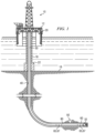
- FIG. 1 depicts a drilling rig 10 suitable for using various method embodiments disclosed herein.
- a semisubmersible drilling platform 12 is positioned over an oil or gas formation disposed below the sea floor 16.
- a subsea conduit 18 extends from deck 20 of platform 12 to a wellhead installation 22.
- the platform may include a derrick and a hoisting apparatus for raising and lowering a drill string 30, which, as shown, extends into wellbore 40 and includes a drill bit 32 and a rotary steerable tool 60.
- Drill string 30 may further include a downhole drilling motor, a downhole telemetry system, and one or more MWD or LWD tools including various sensors for sensing downhole characteristics of the wellbore and the surrounding formation.
- the disclosed embodiments are not limited in these regards.
- FIG. 1 is merely an example. It will be further understood that disclosed embodiments are not limited to use with a semisubmersible platform 12 as illustrated on FIG. 1 . The disclosed embodiments are equally well suited for use with any kind of subterranean drilling operation, either offshore or onshore.
- FIG. 2 depicts the lower BHA portion of drill string 30 including drill bit 32 and rotary steerable tool 60.
- rotary steerable tool body 62 is connected with the drill bit 32 and may be (or may not be) configured to rotate with the drill bit 32.
- Rotary steerable tools 60 include steering elements that may be actuated to control and/or change the direction of drilling the wellbore 40.
- substantially any suitable rotary steerable tool configuration may be used.
- Various rotary steerable tool configurations are known in the art.
- the AutoTrak ® rotary steerable system (available from Baker Hughes), and the GeoPilot rotary steerable system (available from Sperry Drilling Services) include a substantially non-rotating (or slowly rotating) outer housing employing blades that engage the wellbore wall. Engagement of the blades with the wellbore wall is intended to eccenter the tool body, thereby pointing or pushing the drill bit in a desired direction while drilling.
- a rotating shaft deployed in the outer housing transfers rotary power and axial weight-on-bit to the drill bit during drilling.
- Accelerometer and magnetometer sets may be deployed in the outer housing and therefore are non-rotating or rotate slowly with respect to the wellbore wall.
- the PowerDrive rotary steerable systems (available from Schlumberger) fully rotate with the drill string (i.e., the outer housing rotates with the drill string).
- the PowerDrive Xceed makes use of an internal steering mechanism that does not require contact with the wellbore wall and enables the tool body to fully rotate with the drill string.
- the PowerDrive X5, X6, and Orbit rotary steerable systems make use of mud actuated blades (or pads) that contact the wellbore wall. The extension of the blades (or pads) is rapidly and continually adjusted as the system rotates in the wellbore.
- the PowerDrive Archer ® makes use of a lower steering section joined at a swivel with an upper section.
- the swivel is actively tilted via pistons so as to change the angle of the lower section with respect to the upper section and maintain a desired drilling direction as the bottom hole assembly rotates in the wellbore.
- Accelerometer and magnetometer sets may rotate with the drill string or may alternatively be deployed in an internal roll-stabilized housing such that they remain substantially stationary (in a bias phase) or rotate slowly with respect to the wellbore (in a neutral phase).
- the bias phase and neutral phase are alternated during drilling at a predetermined ratio (referred to as the steering ratio).
- FIG. 2 depicts a rotary steerable tool 60
- the disclosed embodiments are not limited to the use of a rotary steerable tool.
- the accelerometer and magnetometer sensor sets 65 and 67 may be deployed and processed in a rotary steerable tool (as depicted on FIG. 2 ), they may also be located elsewhere within the drill string.
- drill string 30 may further include a measurement while drilling tool 80 including corresponding accelerometer and magnetometer sensor sets 65 and 67.
- the MWD tool 80 is commonly deployed further uphole in the drill string (i.e., above the rotary steerable tool 60).
- such MWD tools 80 may rotate with the drill string and may further include a mud pulse telemetry transmitter or other telemetry system, an alternator for generating electrical power, and an electronic controller. It will thus be appreciated that the disclosed embodiments are not limited to any specific deployment location of the accelerometer and magnetometer sensor sets 65 and 67 in the drill string.
- the depicted rotary steerable tool 60 and/or MWD tool include(s) tri-axial accelerometer 65 and tri-axial magnetometer 67 navigation sensor sets, which could be any suitable commercially available devices.
- Suitable accelerometers for use in sensor set 65 may be chosen from among substantially any suitable commercially available devices known in the art.
- Suitable accelerometers may alternatively include micro-electro-mechanical systems (MEMS) solid-state accelerometers, which tend to be shock resistant, high-temperature rated, and inexpensive.
- Suitable magnetic field sensors for use in sensor set 67 may include conventional ring core flux gate magnetometers or conventional magnetoresistive sensors.
- FIG. 2 further includes a diagrammatic representation of the tri-axial accelerometer and magnetometer sensor sets 65 and 67.
- tri-axial it is meant that each sensor set includes three mutually perpendicular sensors, the accelerometers being designated as A x , A y , and A z and the magnetometers being designated as B x , B y , and B z .
- a right handed system is designated in which the z-axis accelerometer and magnetometer ( A z and B z ) are oriented substantially parallel with the tool axis (and therefore the wellbore axis) as indicated (although disclosed embodiments are not limited by such conventions).
- Each of the accelerometer and magnetometer sets may therefore be considered as determining a plane (the x and y-axes) and a pole (the z-axis along the axis of the BHA).
- the gravitational field is taken to be positive pointing downward (i.e., toward the center of the earth) while the magnetic field is taken to be positive pointing towards magnetic north.
- the y-axis is taken to be the toolface reference axis (i.e., gravity toolface GTF equals zero when the y-axis is uppermost and magnetic toolface MTF equals zero when the y-axis is pointing towards the projection of magnetic north in the xy plane).
- the negative signs in the gravity toolface expression arise owing to the convention that the gravity vector is positive in the downward direction while the toolface angle GTF is positive on the high side of the wellbore (the side facing upward).
- the accelerometer and magnetometer sets 65, 67 may be configured for making downhole navigational (surveying) measurements during a drilling operation. Such measurements are well known and commonly used to determine, for example, wellbore inclination, wellbore azimuth, gravity toolface, magnetic toolface, and dipping angle (dip).
- the accelerometers and magnetometers may be electrically coupled to a digital signal processor (or other digital controller) through corresponding signal analog signal conditioning circuits as described in more detail below.
- the signal conditioning circuits may include lowpass filter elements that are intended to band-limit sensor noise and therefore tend to improve sensor resolution and surveying accuracy.
- FIG. 3 depicts a flow chart of one example method embodiment 100 for drilling a subterranean wellbore.
- a bottom hole assembly e.g., as depicted on FIGS. 1 and 2
- Triaxial accelerometer and triaxial magnetometer measurements are made at 104 while drilling in 102 (i.e., while rotating the bottom hole assembly in the wellbore to drill the well).
- the accelerometer measurements and magnetometer measurements are synchronized at 106 to obtain corrected/synchronized measurements.
- the accelerometer and magnetometer measurements may be synchronized by compensating for temperature drift, phase shift and attenuation of the measurements, and/or distortion caused by magnetic interference.
- the corrected/synchronized measurements may then be processed at 108 to compute the desired wellbore survey parameters, for example, one or more of wellbore inclination, wellbore azimuth, and dip angle.
- the wellbore survey parameters may then optionally be used for wellbore position and trajectory control at 110 while drilling in 102.
- the direction of drilling in 102 may be adjusted in response to the survey parameters (e.g., by adjusting the position of blades or other actuating components in a rotary steerable tool) to continue drilling along a predetermined path.
- phase difference a delay
- attenuation difference between the accelerometer and magnetometer data streams.
- phase and attenuation differences may be caused, for example, by the corresponding circuits used to receive the analog data streams from the accelerometer and magnetometer sets.
- each of the circuits tends to attenuate and delay the received data stream.
- the attenuation and phase delay can vary (e.g., can significantly vary) with downhole temperature.
- the attenuation and delay can be further influenced by radial magnetic interference, such as fields induced in the drill collar, by the Earth's magnetic field, or from electrical currents in a nearby power bus. If unaccounted, these phase and attenuation differences can result in significant errors in computed survey parameters, particularly in wellbore azimuth and dip angle which are computed using a combination of accelerometer and magnetometer measurements.
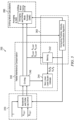
- FIG. 4 depicts a schematic diagram of an embodiment of a system 120 suitable for executing method 100.
- the system 120 includes a drill collar 122 (such as drill string 30 including rotary steerable tool 60 and/or MWD tool 80) rotating in a subterranean wellbore (e.g., rotating while rotary drilling the wellbore).
- the drill collar 122 includes triaxial accelerometer and triaxial magnetometer sets 65, 67 deployed therein and configured to measure the Earth's gravitational and magnetic fields while rotating. The gravitational and magnetic fields of the Earth are depicted at 124 and 126 as A and B .
- each of the accelerometers in the triaxial accelerometer set 65 measures a corresponding time varying gravitational field, A x ( t ), A y ( t ), A z ( t ).
- each of the magnetometers in the triaxial magnetometer set 67 measures a corresponding time varying magnetic field, B x ( t ), B y ( t ), B z ( t ).
- These time varying gravitational field and magnetic field measurements are received (and filtered) by corresponding signal conditioning circuits 140 and 150.
- the time varying measurements are then digitized at some predetermined frequency (e.g., in a range from about 100 to about 1000 Hz) via an analog to digital converter 160.
- the digitized measurements A x , A y , A z and B x , B y , B z are then received by a digital signal processor 180 where they are processed to compute the various survey parameters (e.g., including wellbore inclination, wellbore azimuth, gravity toolface, magnetic toolface, and dip) in real-time while drilling.
- various survey parameters e.g., including wellbore inclination, wellbore azimuth, gravity toolface, magnetic toolface, and dip
- the real-time survey measurements may be computed at substantially any frequency, for example, in a range from about 0.1 to about 100 Hz depending on how much averaging is employed. Such a measurement frequency corresponds to a measured depth interval ranging from a fraction of an inch to a few inches (as compared to 30 or 90 feet for conventional static measurements).
- One aspect of the disclosed embodiments is the discovery that rotation of the drill collar 122 in the Earth's magnetic field (or in the presence of other magnetic interference) may create an additional magnetic field in the collar bore. This additional field can cause the time varying magnetic field measured by the individual magnetometers in the magnetometer set 67 to lag behind the Earth's magnetic field. Such drill collar lag is depicted at 130 and represented by ⁇ 1 .
- the time varying gravitational and magnetic field measurements are received by corresponding accelerometer and magnetometer electrical signal conditioning circuits 140 and 150 prior to digitizing the signals via ADC 160.
- the accelerometer circuit 140 induces a corresponding time lag and attenuation ⁇ 3 in the accelerometer measurements while the magnetometer circuit 150 induces a corresponding time lag and attenuation ⁇ 2 in the magnetometer measurements.
- the product (or convolution) of lags ⁇ 1 and ⁇ 2 is not equal to lag ⁇ 3 such that the time varying gravitational and magnetic field measurements are generally out of phase (i.e., not synchronized). This can induce errors in the computed survey parameters, particularly in the computed wellbore azimuth and dip since these parameters are computed using both accelerometer and magnetometer measurements.
- FIG. 5 depicts a block diagram of an example method 200 for computing survey parameters in real time while drilling a subterranean wellbore.
- the method may be executed, for example, using a digital signal processor located in the bottom hole assembly (e.g., DSP 180 shown on FIG. 4 ).
- the method 200 includes four blocks: (i) a bandwidth compensation block 220, (ii) a radial interference compensation block 240, (iii) a dynamics block 260 in which the position, velocity, and acceleration of the drill collar are computed, and (iv) a drilling mode survey block 280 in which the survey parameters are computed.
- a bandwidth compensation block 220 e.g., a radial interference compensation block 240
- a dynamics block 260 in which the position, velocity, and acceleration of the drill collar are computed
- a drilling mode survey block 280 in which the survey parameters are computed.
- the digitized accelerometer and magnetometer measurements are first processed by bandwidth compensation block 220 and then by radial interference compensation block 240 (with block 240 receiving the output from block 220 as input). It will be appreciated that such depiction is for convenience only as the processing in block 240 may alternatively precede the processing in block 220 (such that the output from block 240 is received as input in block 220). The disclosed embodiments are not limited in this regard.
- digitized accelerometer and magnetometer measurements A x , A y , A z and B x , B y , B z along with corresponding temperature measurements T are processed in the bandwidth correction block 220 to compensate (correct) attenuation and delay of the front end analog measurements (the time varying gravitational field and magnetic field measurements described above with respect to FIG. 4 ) introduced by signal conditioning circuits 140 and 150. Such compensation may be understood to synchronize the accelerometer and magnetometer measurements.
- the bandwidth correction block 220 may optionally be configured to correct for temperature variation in the time constants of the signal conditioning circuits 140 and 150 (which induce lags ⁇ 3 and ⁇ 2 ). In various additional embodiments, the bandwidth correction block 220 may further apply a collar lag compensation to correct for the effect of lag ⁇ 1 on the magnetometer measurements.
- FIG. 6 depicts a plot of magnetic field strength versus time for a magnetometer rotating at 240 rpm.
- the input magnetic field is depicted at 302 while the magnetometer output is depicted at 304.
- the magnetometer output is attenuated by about 1-5%, e.g., 2% or 4%, and undergoes a phase delay of about 5-15 degrees, e.g., 7 degrees, 10 degrees, or 13 degrees.
- the accelerometer output may also be attenuated and phased delayed (although generally to a different degree than that of the magnetometer output).
- the attenuation and phase delay may vary depending on the circuits used, the temperature, and a variety of other factors.
- the signal conditioning circuits 140 and 150 may be modelled as low pass filters having corresponding time constants.
- each of the conditioning circuits may be modelled (e.g., approximated) as an RC filter circuit such as depicted on FIG. 7 in which S uf represents the unfiltered sensor signal and S f represents the filtered sensor signal.
- S uf represents the input accelerometer signal (the accelerometer signal received by the circuit 140)
- S f represents the output accelerometer signal.
- S uf represents the input magnetometer signal (the magnetometer signal received by the circuit 150) and S f represents the output magnetometer signal.
- the symbol ⁇ is used herein to represent both a time constant (as in Equation 1) and the corresponding time lag and attenuation induced by the time constant (e.g., as in FIG. 4 ).
- a time constant of a circuit such as signal conditioning circuits 140 and 150 may be thought of as inducing a corresponding time lag and attenuation in a signal and that the induced lag and attenuation is a function of the signal frequency.
- ⁇ may be related to the magnetic or gravity toolface, while ⁇ and ⁇ may related to the first and second derivatives of the toolface.
- ⁇ , ⁇ , and ⁇ may be computed in and received from dynamics block 260 as described in more detail below.
- bandwidth correction block 220 may compensate for the attenuation and phase delay in the accelerometer and magnetometer measurements (e.g., synchronize the measurements) via processing the digitized measurements according to Equation 2.
- a c represent the compensated accelerometer measurement
- a uc represent the uncompensated accelerometer measurement (e.g., A x , A y , and/or A z as measured)
- a ⁇ represents the transverse component of the gravity field.
- Equation 3 represents the time constant of the accelerometer conditioning circuit 140.
- ⁇ , ⁇ , and ⁇ represent the rotational position, the rotational velocity, and the rotational acceleration of the drill collar (or the accelerometers in the tool collar) and may be determined, for example, as described below with respect to block 260.
- each of the triaxial accelerometer measurements ( A x , A y , and A z ) may be compensated according to Equation 3.
- the cross-axial (transverse) measurements A x and A y ) are compensated.
- B c represent the compensated magnetometer measurements
- B uc represent the uncompensated magnetometer measurements
- B ⁇ represents the transverse component of the magnetic field.
- ⁇ 2 represents the time constant of the magnetometer conditioning circuit 150.
- ⁇ , ⁇ , and ⁇ represent rotational position, the rotational velocity, and the rotational acceleration of the drill collar (or the magnetometers in the tool collar) and may be determined, for example, as described in more detail below.
- each of the triaxial magnetometer measurements ( B x , B y , and B z ) may be compensated according to Equation 3.
- only the cross-axial (transverse) measurements ( B x and B y ) are compensated.
- bandwidth correction block 220 may further correct for the temperature variation in time constants ⁇ 3 and ⁇ 2 of the signal conditioning circuits 140 and 150.
- the time constants ⁇ 3 and ⁇ 2 for each of the signal conditioning circuits 140 and 150 may be measured at various temperatures (e.g., ranging from 25 to 175 degrees C). These temperature dependent time constant measurements may then be fit to corresponding functions f 3 and f 2 (such as to polynomial functions) or stored in corresponding lookup tables.
- Block 220 may be configured to process the downhole temperature measurements T to compute corresponding values of ⁇ 3 and ⁇ 2 according to f 3 and f 2 (or to obtain the values from corresponding lookup tables). These temperature dependent values of ⁇ 3 and ⁇ 2 may then be used in Equations 3 and 4 to compute the corresponding compensated measurements.
- bandwidth correction block 220 may further apply a collar lag compensation to correct for drill collar lag.
- drill collar lag may result as the Earth's magnetic field (or other interference magnetic field) induces an electrical current in the wall of the rotating drill collar. This electrical current in turn induces a magnetic field in the drill collar bore (e.g., at the location of the magnetometers). The net effect tends to cause the measured magnetic field to lag behind (i.e., to be phase delayed with respect to) the Earth's true magnetic field.
- Drill collar lag may be modelled (or approximated) as a low pass filter (in a manner similar to that described above for the signal conditioning circuits 140 and 150) having a time constant ⁇ 1 . Therefore, in certain embodiments, the magnetometer measurements may be compensated for attenuation and delay introduced by both collar lag and conditioning circuit 150.
- FIG. 8 depicts a block diagram of one example embodiment in which the attenuation and delay introduced by collar lag and conditioning circuit 150 are modelled as first and second cascading low pass filters 310 and 320.
- the unfiltered magnetometer input B uf (representing Earth's true magnetic field) is attenuated and delayed by a first low pass filter 310 that models the effect of collar lag.
- the output from the first low pass filter 310 B f 1 is then input into a second low pass filter 320 (that models the magnetometer conditioning circuit 150) where it is further attenuated and delayed.
- the output from the second low pass filter 320 B f 12 (which has been attenuated and delayed by both low pass filters) is then input into the ADC.
- bandwidth correction block 220 may compensate for both collar lag and conditioning circuit 150. Compensation takes place from right to left in FIG. 8 .
- the digitized magnetometer measurements are first compensated for the delay induced by the conditioning circuit 150 (the second low pass filter 320) and then the resultant, partially compensated quantity is further compensated for the delay induced by collar lag (the first low pass filter 310).
- the digitized magnetometer measurements may be compensated according to Equations 5 and 6.
- B c 2 B uc + B ⁇ cos ⁇ ⁇ 2 2 ⁇ 2 3 ⁇ 2 3 ⁇ + 3 ⁇ 2 3 ⁇ 2 ⁇ 2 4 ⁇ 4 + B ⁇ sin ⁇ ⁇ 2 ⁇ + ⁇ 2 2 ⁇ + ⁇ 2 3 ⁇ 3 6 ⁇ 2 4 ⁇ 2 ⁇
- B c 12 B c 2 + B ⁇ cos ⁇ ⁇ 1 2 ⁇ 2 3 ⁇ 1 3 ⁇ + 3 ⁇ 1 3 ⁇ 2 ⁇ 1 4 ⁇ 4 + B ⁇ sin ⁇ ⁇ 1 ⁇ + ⁇ 1 2 ⁇ + ⁇ 1 3 ⁇ 3 6 ⁇ 1 4 ⁇ 2 ⁇
- B uc represents the uncompensated (digitized) magnetometer measurements
- B c 2 represents a partial compensation in which the measurements are compensated for the delay induced by conditioning circuit 150 (and is analogous to B f 1 in FIG.
- B c 12 represents a full compensation in which the measurements are compensated for delay induced by both collar lag and the conditioning circuit 150 (and is analogous to B uf in FIG. 8 ),
- ⁇ 1 represents the time constant of the first low pass filter 310 (the collar lag), and
- ⁇ 2 represents the time constant of the second low pass filter 320 (conditioning circuit 150).
- the parameters ⁇ , ⁇ , and ⁇ are as defined previously.
- correction block 220 may further correct for the temperature variation in time constants ⁇ 1 and ⁇ 2 .
- f 2 may be a polynomial function obtained by empirically fitting temperature dependent time constant data (e.g., over a temperature range from 25 to 175 degrees C). It has been found that drill collar lag tends to vary linearly with temperature (in the above recited range of temperatures), such that f 1 may sometimes be approximated as a linear function (a first order polynomial).
- Block 220 may be configured to process the downhole temperature measurements T to compute corresponding values of ⁇ 1 and ⁇ 2 according to f 1 and f 2 (or to obtain the values from corresponding lookup tables). These temperature dependent values of ⁇ 1 and ⁇ 2 may then be used in Equations 5 and 6 to compute the fully compensated magnetic field measurement B c 12 (i.e., the fully compensated magnetometer measurements).
- the compensated accelerometer and magnetometer measurements may be further processed by radial interference compensation block 240 to remove distortion or interference in the transverse components of the magnetometer measurements (e.g., B x , and B y ) .
- B x and B y trace out a circle in an x-y plot as the drill string rotates in the wellbore (e.g., while drilling). Such a circle is centered at the origin and has a radius equal to B ⁇ .
- Local disturbances or magnetic interference can create a non-uniform magnetic field such that the locus of B x and B y is not centered at the origin and/or traces out an ellipse (rather than a circle).
- Such disturbances or magnetic interference may be caused, for example, by electrical current flowing through a power bus in the vicinity of the magnetometers.
- a mismatch in the calibrated gains and offsets of the x- and y-axis magnetometers may also result in locus of B x and B y tracing an off-centered ellipse.
- Block 240 is configured to correct B x and B y for such distortion and/or interference.
- magnetometer measurements B x and B y may be collected and binned into a predefined number of azimuthal sectors at 242 while rotating (drilling). For example, the magnetometer measurements may be binned into 36 azimuthal sectors (each of which extends 10 degrees).
- the binned measurements are received by a fitting algorithm at 244.
- a best fitting vector p may be computed iteratively for each pair of B x and B y measurements in Equation 8, for example, by starting with an estimated p and generating a Taylor series expansion around the estimate. The vector p approaches a best fit when the higher order terms in the Taylor series approach zero (i.e., are less than a threshold).
- the rotational position, velocity, and acceleration of the drill collar may be computed at block 260 using substantially any suitable methodology.
- the rotational position, velocity, and acceleration of the drill collar may alternatively (or additionally) be computed using a finite impulse response (FIR) filter.
- FIR finite impulse response
- Equation 11 represents an FIR filter structure with ( H T H ) -1 H T being a 3 ⁇ K matrix and ⁇ a moving window of K ⁇ 1 observations.
- a new (or updated) value for the position, velocity, and acceleration of the drill collar may be computed.
- the output from block 260 e.g., the vector x in Equation 11
- various survey parameters may be computed at block 280 from the compensated accelerometer and magnetometer measurements received from blocks 220 and 240.
- the computed survey parameters may include, for example, wellbore inclination, wellbore azimuth, gravity toolface, magnetic toolface, and dip.
- a c ⁇ and A cz may be averaged over several tool rotations while drilling.
- B cx and B cy represent the x- and y-axis compensated magnetometer measurements and where the angle ⁇ may be determined, for example, as follows:
- Drill string shock and vibration may be a potential source of error during drilling mode survey operations. Shock and vibration can be particularly problematic during vertical or near-vertical drilling operations.
- the above described embodiments may optionally further include an additional vibration compensation module, for example, including a Kalman filter and/or an averaging routine to compensate for such shock and vibration.
- FIG. 9 depicts a block diagram of an alternative example method 350 for computing survey parameters in real time while drilling a subterranean wellbore.
- Method 350 is largely identical to method 200 ( FIG. 5 ) in that it includes (i) a bandwidth compensation block 220, (ii) a radial interference compensation block 240, (iii) a dynamics block 260 in which the position, velocity, and acceleration of the drill collar are computed.
- Method 350 further includes a drilling mode survey block 380 at which the survey parameters are computed.
- Method 350 differs from method 200 in that the drilling mode survey block 380 includes an optional vibration compensation module 382 configured to compensate for drilling mode noise (e.g., caused by drill string shock and vibration) and a drilling mode survey module 390 in which the survey parameters are computed.
- the survey module 390 is similar to survey block 280 depicted on FIG. 5 in that it is configured to compute various survey parameters from the compensated and filtered accelerometer and magnetometer measurements received module 382.
- the compensation module 382 includes a Kalman filter module 384 and an averaging module 386.
- Modules 384 and 386 receive input parameters from radial interference compensation block 240 and dynamics block 260 as indicated in FIG. 9 .
- the filtered and averaged output from modules 384 and 386 is received by the survey module 390 as also depicted.
- FIG. 10 embodiment may depict the use of parallel Kalman filter and averaging modules 384 and 386, it will be appreciated that the invention is not limited in these regards.
- the compensation module 382 may include only a Kalman filtering module 384.
- the compensation module 382 may include only an averaging module 386.
- Example Kalman filtering modules 384 and averaging modules 386 are described in more detail below.
- FIG. 11 depicts one example implementation of the Kalman filter at 400.
- a Kalman filter (such as module 384 in FIG. 10 ) may be used to estimate the state of the system (the state of the drilling system) based on a sequence of noisy observations (e.g., the noisy magnetic field and gravity measurements made in a vibrating drill string).
- a measurement vector Z may be formed at 410 from the synchronized accelerometer and magnetometer measurements (e.g., received from blocks 240 and 260 in FIG. 9 ).
- V i ⁇ 1 i F i V i ⁇ 1 i ⁇ 1 + B i U i
- V i ⁇ 1 i represents the forecast of the current vector state (the current state of the system) based on the final previous vector state V i ⁇ 1 i ⁇ 1 (the previous state of the system), for example, as follows: A z i A z i ⁇ 1 A z i ⁇ 2 A x i cos ⁇ i A y i sin ⁇ i A x i ⁇ 1 cos ⁇ i ⁇ 1 A y i ⁇ 1 sin ⁇ i ⁇ 1 A x i ⁇ 2 cos ⁇ i ⁇ 2 A y i
- averaging module 386 may be further implemented to compensate for the influence of drill string shock and vibration.
- the computed survey parameters may be stored in downhole memory and transmitted to the surface, for example, via mud pulse telemetry, electromagnetic telemetry (or other telemetry techniques).
- the accuracy of the computed parameters may be sufficient such that the drilling operation may forego the use of conventional static surveying techniques.
- the wellbore survey may be constructed at the surface based upon the transmitted measurements.
- the survey parameters measured at 108 may be used to control and/or change the direction of drilling in 110.
- the wellbore (or a portion of the wellbore) is drilled along a drill plan, such as a predetermined direction (e.g., as defined by the wellbore inclination and the wellbore azimuth) or a predetermined curvature.
- the computed wellbore inclination and wellbore azimuth may be compared with a desired inclination and azimuth.
- the drilling direction may be changed, for example, in order to meet the drill plan, or when the difference between the computed and desired direction or curvature exceeds a predetermined threshold. Such a change in drilling direction may be implemented, for example, via actuating steering elements in a rotary steerable tool deployed above the bit.
- the survey parameters may be sent directly to an RSS, which processes the survey parameters compared to the drill plan, (e.g., predetermined direction or predetermined curve) and changes drilling direction in order to meet the plan.
- the survey parameters may be sent to the surface using telemetry so that the survey parameters may be analysed.
- drilling parameters e.g., weight on bit, rotation rate, mud pump rate, etc.
- a downlink may be sent to the RSS to change the drilling direction.
- both downhole and surface control may be used.
- a suitable controller may include, for example, a programmable processor, such as a digital signal processor or other microprocessor or microcontroller and processor-readable or computer-readable program code embodying logic.
- a suitable processor may be utilized, for example, to execute the method embodiments (or various steps in the method embodiments) described above with respect to FIGS. 3 , 5 , and 9-11 .
- a suitable controller may also optionally include other controllable components, such as sensors (e.g., a temperature sensor), data storage devices, power supplies, timers, and the like.
- the controller may also be disposed to be in electronic communication with the accelerometers and magnetometers, for example, as depicted on FIG. 4 .
- a suitable controller may also optionally communicate with other instruments in the drill string, such as, for example, telemetry systems that communicate with the surface.
- a suitable controller may further optionally include volatile or non-volatile memory or a data storage device.
- references to "one embodiment” or “an embodiment” of the present disclosure are not intended to be interpreted as excluding the existence of additional embodiments that also incorporate the recited features.
- any element described in relation to an embodiment herein may be combinable with any element of any other embodiment described herein.
- any references to “up” and “down” or “above” or “below” are merely descriptive of the relative position or movement of the related elements.
Landscapes
- Life Sciences & Earth Sciences (AREA)
- Engineering & Computer Science (AREA)
- Geology (AREA)
- Mining & Mineral Resources (AREA)
- Physics & Mathematics (AREA)
- Environmental & Geological Engineering (AREA)
- Fluid Mechanics (AREA)
- General Life Sciences & Earth Sciences (AREA)
- Geochemistry & Mineralogy (AREA)
- Geophysics (AREA)
- Geophysics And Detection Of Objects (AREA)
Claims (11)
- Procédé destiné au forage d'un puits de forage souterrain, le procédé comprenant :(a) le forage (102) du puits de forage souterrain (40) par l'intermédiaire de la rotation d'un train de forage dans celui-ci, le train de forage (30) comportant un trépan, un ensemble accéléromètre triaxial (65) et un ensemble magnétomètre triaxial (67) ;(b) le fait d'amener (104) l'ensemble accéléromètre triaxial (65) et l'ensemble magnétomètre triaxial (67) à effectuer des mesures analogiques correspondantes d'accéléromètre triaxial (Ax(t), Ay(t) Az(t)) (Bx(t), By(t) Bz(t)) et des mesures analogiques de magnétomètre triaxial (Bx(t), By(t) Bz(t)) pendant le forage en (a) ;(c) le filtrage des mesures de magnétomètre triaxial (Bx(t), By(t) Bz(t)) effectuées en (b) à l'aide d'un premier circuit analogique (140) situé dans le train de forage (30) pour obtenir des mesures de magnétomètre triaxial filtrées ;(d) le filtrage des mesures d'accéléromètre triaxial (Ax(t), Ay(t) Az(t)) effectuées à l'aide d'un second circuit analogique (150) situé dans le train de forage (30) pour obtenir des mesures d'accéléromètre triaxial filtrées ;(e) la numérisation (160) des mesures du magnétomètre triaxial filtrées (Bx(t), By(t) Bz(t)) obtenues en (c) et des mesures d'accéléromètre triaxial filtrées (Ax(t), Ay(t) Az(t)) obtenues en (d) pour obtenir des mesures de magnétomètre triaxial numérisées (Bx, By Bz ) et des mesures d'accéléromètre triaxial numérisées (Ax(t), Ay(t) Az(t)), le procédé étant caractérisé par les étapes suivantes :(f) le traitement des mesures de magnétomètre numérisées (Bx, By Bz) pour supprimer un premier décalage temporel (τ2) et obtenir ainsi des mesures de magnétomètre compensées ; et(g) le traitement des mesures d'accéléromètre numérisées (Ax, Ay Az) pour supprimer un second décalage temporel (τ 3) et obtenir ainsi des mesures d'accéléromètre compensées ;(h) la traitement des mesures de magnétomètre compensées et des mesures d'accéléromètre compensées pour calculer une inclinaison et un azimut du puits de forage souterrain pendant le forage en (a).
- Procédé selon la revendication 1, comprenant en outre :(i) la modification d'une direction de forage du puits de forage souterrain en (a) en réponse à au moins un élément parmi l'inclinaison et l'azimut calculés en (h).
- Procédé selon la revendication 1, dans lequel :(b) celui-ci comprend en outre le fait d'amener un capteur de température à mesurer une température de fond de trou pendant la rotation en (a) ;(f) celui-ci comprend en outre (i) le traitement de la température de fond de trou pour calculer une première constante de temps (τ 1) et une troisième constante de temps (τ2) (ii) le traitement des mesures du magnétomètre pour calculer une position de rotation, une vitesse de rotation et une accélération de rotation du train de forage et (iii) le traitement de la première constante de temps (τ1), de la troisième constante de temps (τ2) et de la position de rotation, de la vitesse de rotation et de l'accélération de rotation du train de forage pour supprimer le premier décalage temporel et le troisième décalage temporel des mesures du magnétomètre ; et(g) celui-ci comprend en outre (i) le traitement de la température de fond de trou pour calculer une deuxième constante de temps et (ii) le traitement de la deuxième constante de temps (τ3) et de la position de rotation, de la vitesse de rotation et de l'accélération de rotation du train de forage pour supprimer le second décalage temporel des mesures d'accéléromètre.
- Procédé selon la revendication 3, dans lequel le premier décalage temporel et le troisième décalage temporel sont supprimés de manière séquentielle des mesures du magnétomètre en (f)(iii).
- Procédé selon la revendication 1, dans lequel le traitement en (f) comprend en outre (i) l'ajustement des composantes transversales des mesures du magnétomètre à une ellipse pour calculer les premier et second décalages et les première et seconde atténuations de ceux-ci et (ii) la suppression des premier et second décalages et des première et seconde atténuations des mesures du magnétomètre.
- Procédé selon la revendication 1, dans lequel (d) comprend en outre (i) le traitement (384) des mesures d'accéléromètre et de magnétomètre synchronisées obtenues en (c) avec un filtre de Kalman (384) pour obtenir des mesures filtrées et (ii) le traitement des mesures filtrées pour calculer au moins une inclinaison et un azimut du puits de forage souterrain pendant le forage en (a).
- Procédé selon la revendication 1, dans lequel (d) comprend en outre (i) le traitement (384) des mesures d'accéléromètre et de magnétomètre synchronisées obtenues en (c) avec un filtre de Kalman pour obtenir des mesures filtrées, (ii) le traitement (306) des mesures d'accéléromètre et de magnétomètre synchronisées obtenues en (c) pour calculer des mesures moyennes et (iii) le traitement des mesures filtrées obtenues en (i) et des mesures moyennes obtenues en (ii) pour calculer au moins une inclinaison et un azimut du puits de forage souterrain pendant le forage en (a).
- Système destiné au forage d'un puits de forage souterrain, le système comprenant :un ensemble de fond de trou (32, 60) conçu pour forer le puits de forage souterrain (40) par l'intermédiaire de la rotation dans celui-ci d'un train de forage (30) ;un ensemble magnétomètre triaxial (67) et un ensemble accéléromètre triaxial (65) déployés dans l'ensemble de fond de trou (60), l'ensemble magnétomètre triaxial (67) en communication électrique avec un premier circuit analogique (140) et l'ensemble accéléromètre triaxial (65) en communication électrique avec un second circuit analogique (150) ;le premier circuit analogique (140) et le second circuit analogique (150) en communication électrique avec un convertisseur analogique-numérique (160), le convertisseur analogique-numérique (160) étant configuré pour numériser les signaux reçus en provenance du premier circuit analogique (140) et du second circuit analogique (150) ;le convertisseur analogique-numérique (160) en communication électronique avec un processeur de signal numérique (180), le processeur de signal numérique (180) étant configuré pour (i) traiter des mesures de magnétomètre numérisées pour supprimer un premier décalage temporel induit par le premier circuit analogique (140) et obtenir ainsi des mesures de magnétomètre compensées (ii) traiter des mesures d'accéléromètre numérisées pour supprimer un second décalage temporel induit par le second circuit analogique (150) et obtenir ainsi des mesures d'accéléromètre compensées et (iii) traiter les mesures de magnétomètre compensées et les mesures d'accéléromètre compensées pour calculer une inclinaison et un azimut du puits de forage souterrain pendant le forage.
- Système selon la revendication 8, comprenant en outre un outil de forage orientable rotatif (60) déployé dans l'ensemble de fond de trou, l'outil de forage orientable rotatif (60) étant conçu pour modifier une direction de forage du puits de forage souterrain (40) en réponse à l'inclinaison et à l'azimut calculés par le processeur de signal numérique (180).
- Système selon la revendication 8, comprenant en outre :un capteur de température déployé dans l'ensemble de fond de trou et conçu pour mesurer une température de fond de trou pendant le forage,dans lequel le processeur de signal numérique (180) est configuré en outre pour (iv) traiter la température de fond de trou pour calculer une première constante de temps du premier circuit analogique (140) et une seconde constante de temps du second circuit analogique (150) et (v) traiter les mesures du magnétomètre pour calculer une position de rotation, une vitesse de rotation et une accélération de rotation de l'ensemble de fond de trou (32, 60) dans le puits de forage souterrain (40), etdans lequel les mesures de magnétomètre numérisées sont traitées en (i) en combinaison avec la première constante de temps et la position de rotation, la vitesse de rotation et l'accélération de rotation de l'ensemble de fond de trou (32, 60) pour supprimer le premier décalage temporel des mesures du magnétomètre.
- Système selon la revendication 10, dans lequel le processeur de signal numérique (180) est configuré en outre pour traiter la température de fond de trou en (iv) pour calculer un retard de collier, et
dans lequel les mesures de magnétomètre numérisées sont traitées en (i) pour supprimer le premier décalage temporel et le décalage de collier des mesures de magnétomètre.
Applications Claiming Priority (3)
| Application Number | Priority Date | Filing Date | Title |
|---|---|---|---|
| US201862683134P | 2018-06-11 | 2018-06-11 | |
| US201962823112P | 2019-03-25 | 2019-03-25 | |
| PCT/US2019/035149 WO2019240971A1 (fr) | 2018-06-11 | 2019-06-03 | Étude en temps réel pendant le forage |
Publications (3)
| Publication Number | Publication Date |
|---|---|
| EP3810896A1 EP3810896A1 (fr) | 2021-04-28 |
| EP3810896A4 EP3810896A4 (fr) | 2022-02-23 |
| EP3810896B1 true EP3810896B1 (fr) | 2023-04-26 |
Family
ID=68843581
Family Applications (1)
| Application Number | Title | Priority Date | Filing Date |
|---|---|---|---|
| EP19818595.1A Active EP3810896B1 (fr) | 2018-06-11 | 2019-06-03 | Étude en temps réel pendant le forage |
Country Status (5)
| Country | Link |
|---|---|
| US (1) | US11692432B2 (fr) |
| EP (1) | EP3810896B1 (fr) |
| CN (1) | CN112424445B (fr) |
| SA (1) | SA520420885B1 (fr) |
| WO (1) | WO2019240971A1 (fr) |
Families Citing this family (12)
| Publication number | Priority date | Publication date | Assignee | Title |
|---|---|---|---|---|
| GB2581671B (en) * | 2017-12-14 | 2022-04-13 | Halliburton Energy Services Inc | Azimuth estimation for directional drilling |
| US10900346B2 (en) * | 2017-12-15 | 2021-01-26 | Halliburton Energy Services, Inc. | Azimuth determination while rotating |
| WO2020231428A1 (fr) * | 2019-05-15 | 2020-11-19 | Landmark Graphics Corporation | Jumeaux numériques auto-adaptatifs |
| CN112145156B (zh) * | 2020-07-16 | 2021-05-07 | 中国石油大学(华东) | 一种井眼轨迹自适应测斜计算方法 |
| US11965408B2 (en) * | 2020-10-30 | 2024-04-23 | Vector Magnetics, Llc | Magnetic borehole surveying method and apparatus |
| NO20230373A1 (en) * | 2020-11-30 | 2023-04-03 | Scient Drilling Int Inc | Active magnetic ranging while drilling |
| US20230038752A1 (en) * | 2021-08-04 | 2023-02-09 | Nabors Drilling Technologies Usa, Inc. | Methods and apparatus to identify and implement downlink command sequence(s) |
| US11519264B1 (en) * | 2021-11-12 | 2022-12-06 | China Petroleum & Chemical Corporation | Method for obtaining gravity coefficients for orthogonally oriented accelerometer devices during measurement-while-drilling operations |
| CN114755742B (zh) * | 2022-04-15 | 2022-10-14 | 中国科学院地质与地球物理研究所 | 一种随钻方位探测数据同步方法及设备 |
| WO2024011087A1 (fr) * | 2022-07-06 | 2024-01-11 | Schlumberger Technology Corporation | Télémétrie en temps réel pendant le forage |
| CN115434694A (zh) * | 2022-08-24 | 2022-12-06 | 中煤科工西安研究院(集团)有限公司 | 一种煤矿井下多参数随钻测量系统及测量方法 |
| CN117514146B (zh) * | 2024-01-04 | 2024-03-22 | 陕西太合智能钻探有限公司 | 一种测井系统及测井方法 |
Family Cites Families (25)
| Publication number | Priority date | Publication date | Assignee | Title |
|---|---|---|---|---|
| US4813274A (en) | 1987-05-27 | 1989-03-21 | Teleco Oilfield Services Inc. | Method for measurement of azimuth of a borehole while drilling |
| US7114565B2 (en) * | 2002-07-30 | 2006-10-03 | Baker Hughes Incorporated | Measurement-while-drilling assembly using real-time toolface oriented measurements |
| US7650269B2 (en) | 2004-11-15 | 2010-01-19 | Halliburton Energy Services, Inc. | Method and apparatus for surveying a borehole with a rotating sensor package |
| WO2009064728A1 (fr) | 2007-11-12 | 2009-05-22 | Schlumberger Canada Limited | Calcul de la trajectoire d'un puits de forage |
| US7886844B2 (en) | 2007-11-12 | 2011-02-15 | Schlumberger Technology Corporation | Borehole survey method and apparatus |
| EP2523350B1 (fr) * | 2011-05-12 | 2013-10-30 | Siemens Aktiengesellschaft | Un système de génération d'horloge |
| US9982525B2 (en) * | 2011-12-12 | 2018-05-29 | Schlumberger Technology Corporation | Utilization of dynamic downhole surveying measurements |
| US9273547B2 (en) * | 2011-12-12 | 2016-03-01 | Schlumberger Technology Corporation | Dynamic borehole azimuth measurements |
| US10323501B2 (en) * | 2012-04-20 | 2019-06-18 | Gyrodata, Incorporated | Method and apparatus for generating weighted average survey |
| CN103089243B (zh) * | 2013-01-23 | 2015-06-03 | 中北大学 | 一种磁性套管中钻井方位角的测量方法 |
| EP2981673A4 (fr) | 2013-03-31 | 2016-11-16 | Services Petroliers Schlumberger | Détection de tourbillon de fond de trou pendant le forage |
| US10036828B2 (en) * | 2014-01-02 | 2018-07-31 | Shell Oil Company | System and method for making downhole measurements |
| US20150362617A1 (en) * | 2014-06-13 | 2015-12-17 | Reme, L.L.C. | Azimuthal gamma resolver assembly |
| US10094850B2 (en) * | 2014-06-27 | 2018-10-09 | Schlumberger Technology Corporation | Magnetic ranging while rotating |
| US20160041293A1 (en) | 2014-08-07 | 2016-02-11 | Schlumberger Technology Corporation | Method and Apparatus for Magnetic Ranging While Rotating |
| US10378286B2 (en) * | 2015-04-30 | 2019-08-13 | Schlumberger Technology Corporation | System and methodology for drilling |
| EP3294990A4 (fr) * | 2015-05-13 | 2018-08-08 | Conoco Phillips Company | Grand moteur d'analyse de données de forage |
| WO2016200766A1 (fr) * | 2015-06-10 | 2016-12-15 | Schlumberger Technology Corporation | Synchronisation hors ligne de journaux de mwd/lwd |
| CN106437683B (zh) | 2016-08-29 | 2017-09-01 | 中国科学院地质与地球物理研究所 | 一种旋转状态下重力加速度测量装置与提取方法 |
| CN206091970U (zh) * | 2016-08-29 | 2017-04-12 | 中国科学院地质与地球物理研究所 | 一种旋转状态下重力加速度测量装置 |
| CN206158732U (zh) * | 2016-08-29 | 2017-05-10 | 中国科学院地质与地球物理研究所 | 一种近钻头钻具姿态随钻测量装置 |
| CN106907142B (zh) * | 2017-01-20 | 2018-07-17 | 中国科学院地质与地球物理研究所 | 一种近钻头方位动态测量装置与测量方法 |
| CN107829726B (zh) * | 2017-12-14 | 2024-05-14 | 杭州丰禾石油科技有限公司 | 一种随钻测井仪器 |
| GB2581671B (en) | 2017-12-14 | 2022-04-13 | Halliburton Energy Services Inc | Azimuth estimation for directional drilling |
| US10895143B2 (en) * | 2018-05-18 | 2021-01-19 | Scientific Drilling International, Inc. | In-situ downhole measurement correction and control |
-
2019
- 2019-06-03 US US16/973,696 patent/US11692432B2/en active Active
- 2019-06-03 CN CN201980046712.8A patent/CN112424445B/zh active Active
- 2019-06-03 WO PCT/US2019/035149 patent/WO2019240971A1/fr unknown
- 2019-06-03 EP EP19818595.1A patent/EP3810896B1/fr active Active
-
2020
- 2020-12-10 SA SA520420885A patent/SA520420885B1/ar unknown
Also Published As
| Publication number | Publication date |
|---|---|
| WO2019240971A1 (fr) | 2019-12-19 |
| CN112424445B (zh) | 2024-06-14 |
| US20210254448A1 (en) | 2021-08-19 |
| US11692432B2 (en) | 2023-07-04 |
| CN112424445A (zh) | 2021-02-26 |
| SA520420885B1 (ar) | 2023-10-29 |
| EP3810896A4 (fr) | 2022-02-23 |
| EP3810896A1 (fr) | 2021-04-28 |
Similar Documents
| Publication | Publication Date | Title |
|---|---|---|
| EP3810896B1 (fr) | Étude en temps réel pendant le forage | |
| US10584575B2 (en) | Utilization of dynamic downhole surveying measurements | |
| US10995552B2 (en) | Closed loop control of drilling toolface | |
| US9273547B2 (en) | Dynamic borehole azimuth measurements | |
| US10202841B2 (en) | Near-bit tool attitude measurement while drilling apparatus and method | |
| US9926779B2 (en) | Downhole whirl detection while drilling | |
| US11624274B2 (en) | Correction of gyroscopic measurements for directional drilling | |
| AU2014412056B2 (en) | Methods and apparatus for multi-well ranging determination | |
| WO2016022768A1 (fr) | Procédé et appareil pour la télémétrie magnétique en rotation | |
| US11898432B2 (en) | Real time surveying while drilling in a roll-stabilized housing | |
| WO2014160580A1 (fr) | Dispositif et procédé de pilotage géologique en boucle fermée | |
| CA2570080A1 (fr) | Levee de puits de forage | |
| EP2981673A1 (fr) | Détection de tourbillon de fond de trou pendant le forage | |
| WO2024011087A1 (fr) | Télémétrie en temps réel pendant le forage | |
| US20230031743A1 (en) | Method for estimating rate of penetration while drilling | |
| US11549362B2 (en) | Azimuth determination while rotating | |
| WO2024076622A1 (fr) | Dispositifs, systèmes et procédés de surveillance de fond de trou |
Legal Events
| Date | Code | Title | Description |
|---|---|---|---|
| STAA | Information on the status of an ep patent application or granted ep patent |
Free format text: STATUS: THE INTERNATIONAL PUBLICATION HAS BEEN MADE |
|
| STAA | Information on the status of an ep patent application or granted ep patent |
Free format text: STATUS: THE INTERNATIONAL PUBLICATION HAS BEEN MADE |
|
| PUAI | Public reference made under article 153(3) epc to a published international application that has entered the european phase |
Free format text: ORIGINAL CODE: 0009012 |
|
| STAA | Information on the status of an ep patent application or granted ep patent |
Free format text: STATUS: REQUEST FOR EXAMINATION WAS MADE |
|
| 17P | Request for examination filed |
Effective date: 20201210 |
|
| AK | Designated contracting states |
Kind code of ref document: A1 Designated state(s): AL AT BE BG CH CY CZ DE DK EE ES FI FR GB GR HR HU IE IS IT LI LT LU LV MC MK MT NL NO PL PT RO RS SE SI SK SM TR |
|
| AX | Request for extension of the european patent |
Extension state: BA ME |
|
| DAV | Request for validation of the european patent (deleted) | ||
| DAX | Request for extension of the european patent (deleted) | ||
| A4 | Supplementary search report drawn up and despatched |
Effective date: 20220121 |
|
| RIC1 | Information provided on ipc code assigned before grant |
Ipc: E21B 7/04 20060101ALI20220117BHEP Ipc: E21B 41/00 20060101ALI20220117BHEP Ipc: E21B 47/024 20060101ALI20220117BHEP Ipc: E21B 44/00 20060101AFI20220117BHEP |
|
| RIN1 | Information on inventor provided before grant (corrected) |
Inventor name: OROOQ, ZAINAB Inventor name: EDMUNDS, MICHAEL Inventor name: LOWDEN, ROSS Inventor name: BULYCHENKOV, KONSTANTIN Inventor name: PHILLIPS, WAYNE J. |
|
| GRAP | Despatch of communication of intention to grant a patent |
Free format text: ORIGINAL CODE: EPIDOSNIGR1 |
|
| STAA | Information on the status of an ep patent application or granted ep patent |
Free format text: STATUS: GRANT OF PATENT IS INTENDED |
|
| INTG | Intention to grant announced |
Effective date: 20221214 |
|
| RIN1 | Information on inventor provided before grant (corrected) |
Inventor name: OROOQ, ZAINAB Inventor name: EDMUNDS, MICHAEL Inventor name: LOWDEN, ROSS Inventor name: BULYCHENKOV, KONSTANTIN Inventor name: PHILLIPS, WAYNE J. |
|
| GRAS | Grant fee paid |
Free format text: ORIGINAL CODE: EPIDOSNIGR3 |
|
| GRAA | (expected) grant |
Free format text: ORIGINAL CODE: 0009210 |
|
| STAA | Information on the status of an ep patent application or granted ep patent |
Free format text: STATUS: THE PATENT HAS BEEN GRANTED |
|
| AK | Designated contracting states |
Kind code of ref document: B1 Designated state(s): AL AT BE BG CH CY CZ DE DK EE ES FI FR GB GR HR HU IE IS IT LI LT LU LV MC MK MT NL NO PL PT RO RS SE SI SK SM TR |
|
| REG | Reference to a national code |
Ref country code: GB Ref legal event code: FG4D |
|
| REG | Reference to a national code |
Ref country code: CH Ref legal event code: EP |
|
| REG | Reference to a national code |
Ref country code: DE Ref legal event code: R096 Ref document number: 602019028132 Country of ref document: DE |
|
| REG | Reference to a national code |
Ref country code: AT Ref legal event code: REF Ref document number: 1562934 Country of ref document: AT Kind code of ref document: T Effective date: 20230515 |
|
| REG | Reference to a national code |
Ref country code: IE Ref legal event code: FG4D |
|
| REG | Reference to a national code |
Ref country code: LT Ref legal event code: MG9D |
|
| REG | Reference to a national code |
Ref country code: NL Ref legal event code: MP Effective date: 20230426 |
|
| REG | Reference to a national code |
Ref country code: NO Ref legal event code: T2 Effective date: 20230426 |
|
| REG | Reference to a national code |
Ref country code: AT Ref legal event code: MK05 Ref document number: 1562934 Country of ref document: AT Kind code of ref document: T Effective date: 20230426 |
|
| PG25 | Lapsed in a contracting state [announced via postgrant information from national office to epo] |
Ref country code: NL Free format text: LAPSE BECAUSE OF FAILURE TO SUBMIT A TRANSLATION OF THE DESCRIPTION OR TO PAY THE FEE WITHIN THE PRESCRIBED TIME-LIMIT Effective date: 20230426 |
|
| PG25 | Lapsed in a contracting state [announced via postgrant information from national office to epo] |
Ref country code: SE Free format text: LAPSE BECAUSE OF FAILURE TO SUBMIT A TRANSLATION OF THE DESCRIPTION OR TO PAY THE FEE WITHIN THE PRESCRIBED TIME-LIMIT Effective date: 20230426 Ref country code: PT Free format text: LAPSE BECAUSE OF FAILURE TO SUBMIT A TRANSLATION OF THE DESCRIPTION OR TO PAY THE FEE WITHIN THE PRESCRIBED TIME-LIMIT Effective date: 20230828 Ref country code: ES Free format text: LAPSE BECAUSE OF FAILURE TO SUBMIT A TRANSLATION OF THE DESCRIPTION OR TO PAY THE FEE WITHIN THE PRESCRIBED TIME-LIMIT Effective date: 20230426 Ref country code: AT Free format text: LAPSE BECAUSE OF FAILURE TO SUBMIT A TRANSLATION OF THE DESCRIPTION OR TO PAY THE FEE WITHIN THE PRESCRIBED TIME-LIMIT Effective date: 20230426 |
|
| PG25 | Lapsed in a contracting state [announced via postgrant information from national office to epo] |
Ref country code: RS Free format text: LAPSE BECAUSE OF FAILURE TO SUBMIT A TRANSLATION OF THE DESCRIPTION OR TO PAY THE FEE WITHIN THE PRESCRIBED TIME-LIMIT Effective date: 20230426 Ref country code: PL Free format text: LAPSE BECAUSE OF FAILURE TO SUBMIT A TRANSLATION OF THE DESCRIPTION OR TO PAY THE FEE WITHIN THE PRESCRIBED TIME-LIMIT Effective date: 20230426 Ref country code: LV Free format text: LAPSE BECAUSE OF FAILURE TO SUBMIT A TRANSLATION OF THE DESCRIPTION OR TO PAY THE FEE WITHIN THE PRESCRIBED TIME-LIMIT Effective date: 20230426 Ref country code: LT Free format text: LAPSE BECAUSE OF FAILURE TO SUBMIT A TRANSLATION OF THE DESCRIPTION OR TO PAY THE FEE WITHIN THE PRESCRIBED TIME-LIMIT Effective date: 20230426 Ref country code: IS Free format text: LAPSE BECAUSE OF FAILURE TO SUBMIT A TRANSLATION OF THE DESCRIPTION OR TO PAY THE FEE WITHIN THE PRESCRIBED TIME-LIMIT Effective date: 20230826 Ref country code: HR Free format text: LAPSE BECAUSE OF FAILURE TO SUBMIT A TRANSLATION OF THE DESCRIPTION OR TO PAY THE FEE WITHIN THE PRESCRIBED TIME-LIMIT Effective date: 20230426 Ref country code: GR Free format text: LAPSE BECAUSE OF FAILURE TO SUBMIT A TRANSLATION OF THE DESCRIPTION OR TO PAY THE FEE WITHIN THE PRESCRIBED TIME-LIMIT Effective date: 20230727 |
|
| PG25 | Lapsed in a contracting state [announced via postgrant information from national office to epo] |
Ref country code: FI Free format text: LAPSE BECAUSE OF FAILURE TO SUBMIT A TRANSLATION OF THE DESCRIPTION OR TO PAY THE FEE WITHIN THE PRESCRIBED TIME-LIMIT Effective date: 20230426 |
|
| PG25 | Lapsed in a contracting state [announced via postgrant information from national office to epo] |
Ref country code: SK Free format text: LAPSE BECAUSE OF FAILURE TO SUBMIT A TRANSLATION OF THE DESCRIPTION OR TO PAY THE FEE WITHIN THE PRESCRIBED TIME-LIMIT Effective date: 20230426 |
|
| P01 | Opt-out of the competence of the unified patent court (upc) registered |
Effective date: 20231208 |
|
| PG25 | Lapsed in a contracting state [announced via postgrant information from national office to epo] |
Ref country code: MC Free format text: LAPSE BECAUSE OF FAILURE TO SUBMIT A TRANSLATION OF THE DESCRIPTION OR TO PAY THE FEE WITHIN THE PRESCRIBED TIME-LIMIT Effective date: 20230426 |
|
| REG | Reference to a national code |
Ref country code: DE Ref legal event code: R097 Ref document number: 602019028132 Country of ref document: DE |
|
| PG25 | Lapsed in a contracting state [announced via postgrant information from national office to epo] |
Ref country code: SM Free format text: LAPSE BECAUSE OF FAILURE TO SUBMIT A TRANSLATION OF THE DESCRIPTION OR TO PAY THE FEE WITHIN THE PRESCRIBED TIME-LIMIT Effective date: 20230426 Ref country code: SK Free format text: LAPSE BECAUSE OF FAILURE TO SUBMIT A TRANSLATION OF THE DESCRIPTION OR TO PAY THE FEE WITHIN THE PRESCRIBED TIME-LIMIT Effective date: 20230426 Ref country code: RO Free format text: LAPSE BECAUSE OF FAILURE TO SUBMIT A TRANSLATION OF THE DESCRIPTION OR TO PAY THE FEE WITHIN THE PRESCRIBED TIME-LIMIT Effective date: 20230426 Ref country code: MC Free format text: LAPSE BECAUSE OF FAILURE TO SUBMIT A TRANSLATION OF THE DESCRIPTION OR TO PAY THE FEE WITHIN THE PRESCRIBED TIME-LIMIT Effective date: 20230426 Ref country code: EE Free format text: LAPSE BECAUSE OF FAILURE TO SUBMIT A TRANSLATION OF THE DESCRIPTION OR TO PAY THE FEE WITHIN THE PRESCRIBED TIME-LIMIT Effective date: 20230426 Ref country code: DK Free format text: LAPSE BECAUSE OF FAILURE TO SUBMIT A TRANSLATION OF THE DESCRIPTION OR TO PAY THE FEE WITHIN THE PRESCRIBED TIME-LIMIT Effective date: 20230426 Ref country code: CZ Free format text: LAPSE BECAUSE OF FAILURE TO SUBMIT A TRANSLATION OF THE DESCRIPTION OR TO PAY THE FEE WITHIN THE PRESCRIBED TIME-LIMIT Effective date: 20230426 |
|
| REG | Reference to a national code |
Ref country code: CH Ref legal event code: PL |
|
| REG | Reference to a national code |
Ref country code: BE Ref legal event code: MM Effective date: 20230630 |
|
| PG25 | Lapsed in a contracting state [announced via postgrant information from national office to epo] |
Ref country code: LU Free format text: LAPSE BECAUSE OF NON-PAYMENT OF DUE FEES Effective date: 20230603 |
|
| PLBE | No opposition filed within time limit |
Free format text: ORIGINAL CODE: 0009261 |
|
| STAA | Information on the status of an ep patent application or granted ep patent |
Free format text: STATUS: NO OPPOSITION FILED WITHIN TIME LIMIT |
|
| REG | Reference to a national code |
Ref country code: IE Ref legal event code: MM4A |
|
| PG25 | Lapsed in a contracting state [announced via postgrant information from national office to epo] |
Ref country code: LU Free format text: LAPSE BECAUSE OF NON-PAYMENT OF DUE FEES Effective date: 20230603 |
|
| 26N | No opposition filed |
Effective date: 20240129 |
|
| PG25 | Lapsed in a contracting state [announced via postgrant information from national office to epo] |
Ref country code: IE Free format text: LAPSE BECAUSE OF NON-PAYMENT OF DUE FEES Effective date: 20230603 |
|
| PG25 | Lapsed in a contracting state [announced via postgrant information from national office to epo] |
Ref country code: IE Free format text: LAPSE BECAUSE OF NON-PAYMENT OF DUE FEES Effective date: 20230603 Ref country code: CH Free format text: LAPSE BECAUSE OF NON-PAYMENT OF DUE FEES Effective date: 20230630 |
|
| PG25 | Lapsed in a contracting state [announced via postgrant information from national office to epo] |
Ref country code: SI Free format text: LAPSE BECAUSE OF FAILURE TO SUBMIT A TRANSLATION OF THE DESCRIPTION OR TO PAY THE FEE WITHIN THE PRESCRIBED TIME-LIMIT Effective date: 20230426 |
|
| PG25 | Lapsed in a contracting state [announced via postgrant information from national office to epo] |
Ref country code: SI Free format text: LAPSE BECAUSE OF FAILURE TO SUBMIT A TRANSLATION OF THE DESCRIPTION OR TO PAY THE FEE WITHIN THE PRESCRIBED TIME-LIMIT Effective date: 20230426 Ref country code: IT Free format text: LAPSE BECAUSE OF FAILURE TO SUBMIT A TRANSLATION OF THE DESCRIPTION OR TO PAY THE FEE WITHIN THE PRESCRIBED TIME-LIMIT Effective date: 20230426 Ref country code: BE Free format text: LAPSE BECAUSE OF NON-PAYMENT OF DUE FEES Effective date: 20230630 |
|
| PGFP | Annual fee paid to national office [announced via postgrant information from national office to epo] |
Ref country code: NO Payment date: 20240222 Year of fee payment: 6 Ref country code: FR Payment date: 20240328 Year of fee payment: 6 |
|
| PGFP | Annual fee paid to national office [announced via postgrant information from national office to epo] |
Ref country code: GB Payment date: 20240402 Year of fee payment: 6 |
|
| PGFP | Annual fee paid to national office [announced via postgrant information from national office to epo] |
Ref country code: DE Payment date: 20240328 Year of fee payment: 6 |