EP3809723A1 - Hörinstrument - Google Patents
Hörinstrument Download PDFInfo
- Publication number
- EP3809723A1 EP3809723A1 EP20200360.4A EP20200360A EP3809723A1 EP 3809723 A1 EP3809723 A1 EP 3809723A1 EP 20200360 A EP20200360 A EP 20200360A EP 3809723 A1 EP3809723 A1 EP 3809723A1
- Authority
- EP
- European Patent Office
- Prior art keywords
- magnetic core
- coil
- hearing instrument
- axis
- charging
- Prior art date
- Legal status (The legal status is an assumption and is not a legal conclusion. Google has not performed a legal analysis and makes no representation as to the accuracy of the status listed.)
- Pending
Links
Images



Classifications
-
- H—ELECTRICITY
- H04—ELECTRIC COMMUNICATION TECHNIQUE
- H04R—LOUDSPEAKERS, MICROPHONES, GRAMOPHONE PICK-UPS OR LIKE ACOUSTIC ELECTROMECHANICAL TRANSDUCERS; ELECTRIC HEARING AIDS; PUBLIC ADDRESS SYSTEMS
- H04R25/00—Electric hearing aids
- H04R25/60—Mounting or interconnection of hearing aid parts, e.g. inside tips, housings or to ossicles
- H04R25/602—Mounting or interconnection of hearing aid parts, e.g. inside tips, housings or to ossicles of batteries
-
- H—ELECTRICITY
- H04—ELECTRIC COMMUNICATION TECHNIQUE
- H04R—LOUDSPEAKERS, MICROPHONES, GRAMOPHONE PICK-UPS OR LIKE ACOUSTIC ELECTROMECHANICAL TRANSDUCERS; ELECTRIC HEARING AIDS; PUBLIC ADDRESS SYSTEMS
- H04R25/00—Electric hearing aids
- H04R25/55—Electric hearing aids using an external connection, either wireless or wired
- H04R25/554—Electric hearing aids using an external connection, either wireless or wired using a wireless connection, e.g. between microphone and amplifier or using Tcoils
-
- H—ELECTRICITY
- H01—ELECTRIC ELEMENTS
- H01Q—ANTENNAS, i.e. RADIO AERIALS
- H01Q1/00—Details of, or arrangements associated with, antennas
- H01Q1/27—Adaptation for use in or on movable bodies
- H01Q1/273—Adaptation for carrying or wearing by persons or animals
-
- H—ELECTRICITY
- H01—ELECTRIC ELEMENTS
- H01Q—ANTENNAS, i.e. RADIO AERIALS
- H01Q7/00—Loop antennas with a substantially uniform current distribution around the loop and having a directional radiation pattern in a plane perpendicular to the plane of the loop
- H01Q7/06—Loop antennas with a substantially uniform current distribution around the loop and having a directional radiation pattern in a plane perpendicular to the plane of the loop with core of ferromagnetic material
-
- H—ELECTRICITY
- H02—GENERATION; CONVERSION OR DISTRIBUTION OF ELECTRIC POWER
- H02J—ELECTRIC POWER NETWORKS; CIRCUIT ARRANGEMENTS OR SYSTEMS FOR SUPPLYING OR DISTRIBUTING ELECTRIC POWER; SYSTEMS FOR STORING ELECTRIC ENERGY
- H02J50/00—Circuit arrangements or systems for wireless supply or distribution of electric power
- H02J50/005—Mechanical details of housing or structure aiming to accommodate the power transfer means, e.g. mechanical integration of coils, antennas or transducers into emitting or receiving devices
-
- H—ELECTRICITY
- H02—GENERATION; CONVERSION OR DISTRIBUTION OF ELECTRIC POWER
- H02J—ELECTRIC POWER NETWORKS; CIRCUIT ARRANGEMENTS OR SYSTEMS FOR SUPPLYING OR DISTRIBUTING ELECTRIC POWER; SYSTEMS FOR STORING ELECTRIC ENERGY
- H02J50/00—Circuit arrangements or systems for wireless supply or distribution of electric power
- H02J50/10—Circuit arrangements or systems for wireless supply or distribution of electric power using inductive coupling
-
- H—ELECTRICITY
- H02—GENERATION; CONVERSION OR DISTRIBUTION OF ELECTRIC POWER
- H02J—ELECTRIC POWER NETWORKS; CIRCUIT ARRANGEMENTS OR SYSTEMS FOR SUPPLYING OR DISTRIBUTING ELECTRIC POWER; SYSTEMS FOR STORING ELECTRIC ENERGY
- H02J7/00—Circuit arrangements for charging or discharging batteries or for supplying loads from batteries
- H02J7/70—Circuit arrangements for charging or discharging batteries or for supplying loads from batteries characterised by the mechanical construction
-
- H—ELECTRICITY
- H04—ELECTRIC COMMUNICATION TECHNIQUE
- H04R—LOUDSPEAKERS, MICROPHONES, GRAMOPHONE PICK-UPS OR LIKE ACOUSTIC ELECTROMECHANICAL TRANSDUCERS; ELECTRIC HEARING AIDS; PUBLIC ADDRESS SYSTEMS
- H04R1/00—Details of transducers, loudspeakers or microphones
- H04R1/10—Earpieces; Attachments therefor ; Earphones; Monophonic headphones
- H04R1/1025—Accumulators specially adapted for earpieces; Arrangements specially adapted for charging thereof
-
- H—ELECTRICITY
- H04—ELECTRIC COMMUNICATION TECHNIQUE
- H04R—LOUDSPEAKERS, MICROPHONES, GRAMOPHONE PICK-UPS OR LIKE ACOUSTIC ELECTROMECHANICAL TRANSDUCERS; ELECTRIC HEARING AIDS; PUBLIC ADDRESS SYSTEMS
- H04R1/00—Details of transducers, loudspeakers or microphones
- H04R1/10—Earpieces; Attachments therefor ; Earphones; Monophonic headphones
- H04R1/1091—Details not provided for in groups H04R1/1008 - H04R1/1083
-
- H—ELECTRICITY
- H04—ELECTRIC COMMUNICATION TECHNIQUE
- H04R—LOUDSPEAKERS, MICROPHONES, GRAMOPHONE PICK-UPS OR LIKE ACOUSTIC ELECTROMECHANICAL TRANSDUCERS; ELECTRIC HEARING AIDS; PUBLIC ADDRESS SYSTEMS
- H04R25/00—Electric hearing aids
- H04R25/60—Mounting or interconnection of hearing aid parts, e.g. inside tips, housings or to ossicles
- H04R25/609—Mounting or interconnection of hearing aid parts, e.g. inside tips, housings or to ossicles of circuitry
-
- H—ELECTRICITY
- H01—ELECTRIC ELEMENTS
- H01Q—ANTENNAS, i.e. RADIO AERIALS
- H01Q1/00—Details of, or arrangements associated with, antennas
- H01Q1/52—Means for reducing coupling between antennas; Means for reducing coupling between an antenna and another structure
- H01Q1/521—Means for reducing coupling between antennas; Means for reducing coupling between an antenna and another structure reducing the coupling between adjacent antennas
-
- H—ELECTRICITY
- H02—GENERATION; CONVERSION OR DISTRIBUTION OF ELECTRIC POWER
- H02J—ELECTRIC POWER NETWORKS; CIRCUIT ARRANGEMENTS OR SYSTEMS FOR SUPPLYING OR DISTRIBUTING ELECTRIC POWER; SYSTEMS FOR STORING ELECTRIC ENERGY
- H02J2105/00—Networks for supplying or distributing electric power characterised by their spatial reach or by the load
- H02J2105/40—Networks for supplying or distributing electric power characterised by their spatial reach or by the load characterised by the loads connecting to the networks or being supplied by the networks
- H02J2105/46—Medical devices, medical implants or life supporting devices
-
- H—ELECTRICITY
- H04—ELECTRIC COMMUNICATION TECHNIQUE
- H04R—LOUDSPEAKERS, MICROPHONES, GRAMOPHONE PICK-UPS OR LIKE ACOUSTIC ELECTROMECHANICAL TRANSDUCERS; ELECTRIC HEARING AIDS; PUBLIC ADDRESS SYSTEMS
- H04R2225/00—Details of deaf aids covered by H04R25/00, not provided for in any of its subgroups
- H04R2225/31—Aspects of the use of accumulators in hearing aids, e.g. rechargeable batteries or fuel cells
-
- H—ELECTRICITY
- H04—ELECTRIC COMMUNICATION TECHNIQUE
- H04R—LOUDSPEAKERS, MICROPHONES, GRAMOPHONE PICK-UPS OR LIKE ACOUSTIC ELECTROMECHANICAL TRANSDUCERS; ELECTRIC HEARING AIDS; PUBLIC ADDRESS SYSTEMS
- H04R2225/00—Details of deaf aids covered by H04R25/00, not provided for in any of its subgroups
- H04R2225/51—Aspects of antennas or their circuitry in or for hearing aids
-
- H—ELECTRICITY
- H04—ELECTRIC COMMUNICATION TECHNIQUE
- H04R—LOUDSPEAKERS, MICROPHONES, GRAMOPHONE PICK-UPS OR LIKE ACOUSTIC ELECTROMECHANICAL TRANSDUCERS; ELECTRIC HEARING AIDS; PUBLIC ADDRESS SYSTEMS
- H04R2225/00—Details of deaf aids covered by H04R25/00, not provided for in any of its subgroups
- H04R2225/57—Aspects of electrical interconnection between hearing aid parts
Definitions
- the invention relates to a hearing instrument with a rechargeable battery, a charging coil and a transmitting and / or receiving coil.
- hearing instruments which are worn on or in the ear of a user (wearer) and emit an acoustic signal to the hearing of the wearer.
- Hearing instruments include, in particular, devices that pick up ambient sound, modify it in terms of signal technology and emit a modified sound signal to the wearer's hearing.
- a subclass of such hearing instruments classically referred to as “hearing aids” is set up for the care of those with poor hearing who suffer from a hearing loss in the medical sense.
- a hearing aid usually comprises an input transducer, for example in the form of a microphone, a signal processing unit with an amplifier, and an output transducer.
- the output transducer is usually implemented as an electroacoustic transducer, in particular as a miniature loudspeaker, and in this case is also referred to as a “receiver”.
- a miniature loudspeaker in particular as a miniature loudspeaker
- bone conduction hearing aids, implantable or vibrotactile hearing aids are also available on the market. With these, the damaged hearing is stimulated either mechanically or electrically.
- hearing instruments are offered to support the hearing ability of users with normal hearing.
- Such hearing instruments also referred to as "Personal Sound Amplification Products” or “Personal Sound Amplification Devices”("PSAD” for short), have a structure similar to that of conventional hearing aids and also have them the components described above, that is, an input transducer, a signal processing unit and an output transducer.
- the invention also relates to hearing instruments that receive the acoustic signal in a wired or wireless manner from a peripheral device, for example headphones and headsets.
- BTE hearing instruments Behind-The-Ear, also behind-the-ear, BTE for short
- a housing that contains the battery and possibly other components such as input transducers, signal processing, etc.
- the output transducer can be arranged directly in the ear canal of the wearer (in the case of so-called Ex earphone or receiver-in-the-canal (RIC) hearing instruments.
- the output transducer is arranged inside the housing worn behind the ear. In this case, it is conductive a flexible sound tube, also known as a "tube", carries the sound signal of the output transducer from the housing to the auditory canal.
- ITE hearing instruments In so-called ITE hearing instruments ("In-the-Ear”, also “In-the-Ear”, ITE for short), a housing, which contains all functional components of the hearing instrument, at least partially worn in the ear canal.
- CIC hearing instruments Completely-in-Canal
- ITE hearing instruments also “In-the-Ear”, ITE for short
- CIC hearing instruments are similar to ITE hearing instruments, but are worn completely in the ear canal.
- Modern hearing instruments are characterized by an increasing number of integrated functions such as active noise suppression, voice or speech recognition, etc. Hearing instruments therefore have an increasing demand for energy, which can often not be met in a satisfactory manner with today's disposable batteries. Due to the increasing energy demand, but also in the sense of simple and resource-saving handling, therefore, instead of disposable batteries, increasingly powerful rechargeable batteries, in particular lithium-ion batteries (short: Li-ion batteries), are being used as a power source for hearing instruments. Wireless charging technologies are preferably used to charge such batteries. This is done in the hearing instrument Usually a charging coil is integrated, which receives the energy required to charge the battery via an inductive coupling with a charger.
- a charging coil is integrated, which receives the energy required to charge the battery via an inductive coupling with a charger.
- a transmitter and / or receiver coil is often integrated in a modern hearing instrument, by means of which the hearing instrument is connected to an external transmitter and / or receiver via a magnetically inductive coupling, e.g. in a second hearing instrument for the other ear Carrier that can exchange data.
- a charging coil module is known with a charging coil which is wound around the circumference of a hollow, cylindrical magnetic core.
- a rechargeable battery which is charged by means of the battery, is arranged in the interior of the magnetic core.
- the charging coil can also be used as an antenna coil.
- a mobile device with a rechargeable battery, a charging coil and an NFC (Near Field Communication) antenna is known.
- the charging coil and the NFC antenna are arranged in such a way that their coil axes are orthogonal to one another.
- the invention is based on the object of enabling a compact and particularly advantageous arrangement of a transmitting and / or receiving coil (MI antenna) and a charging coil in a hearing instrument.
- MI antenna transmitting and / or receiving coil
- the invention is based on a hearing instrument that has a rechargeable battery, a charging coil for inductively receiving energy for charging the battery and a transmitting and / or receiving coil (MI antenna) for inductive transmission and / or reception of Has data.
- the hearing instrument has a magnetic core, in particular made of soft magnetic ferrite material.
- both the charging coil and the transmitting and / or receiving coil are wound onto this magnetic core.
- the two coils can be designed to be particularly space-saving.
- the charging coil and the MI antenna are preferably wound onto the magnetic core in such a way that their coil axes are aligned exactly or approximately orthogonally to one another.
- This arrangement of the two coils with respect to one another eliminates or at least largely reduces a mutual magnetic influence of the two coils.
- minor deviations from an exactly orthogonal alignment of the coil axes are not critical for the intended effect of magnetic decoupling of the coils.
- the winding of the magnetic core with the two coils is subject to certain manufacturing tolerances, especially if the magnetic core does not have a cuboid shape.
- An exact or approximately orthogonal alignment of the coil axes is therefore already given when the coil axes between them form an angle of 90 ° ⁇ 30 °, preferably 90 ° ⁇ 15 ° and in particular 90 ° ⁇ 5 °.
- the magnetic core is designed as a (pot-like, ring-shaped or, for example, horseshoe-shaped) hollow body in which the battery is received.
- an electronic component of the hearing instrument in particular charging electronics, can also be arranged in the hollow magnetic core within the scope of the invention. Due to the hollow design of the magnetic core and the housing the battery or the electronic component in the magnetic core enables a particularly compact design of the hearing instrument. At the same time, this allows the magnetic core to be designed with a particularly large enclosed volume (in particular with a particularly large cross section) without unduly hindering the arrangement of the other components in the housing. The large volume of the magnetic core in turn enables the MI antenna wound around the magnetic core to be highly effective.
- the magnetic core has a cylindrical shape with two parallel end faces lying opposite one another along an axis and a peripheral wall connecting the end faces.
- the end faces are preferably circular, but can in principle also be oval, polygonal or irregular in shape within the scope of the invention.
- the height of the magnetic core measured along the axis to the width of the magnetic core measured transversely to the axis is in a ratio between 1: 1 and 1: 4 (in the case of non-circular end faces, the width is due to the greatest extent of the magnetic core given transversely to the axis). In particular, the ratio of the height to the width of the magnetic core is approximately 1: 2.5.
- the magnetic core here has the shape of a flat cylinder.
- one of the two coils in particular the MI antenna, is preferably wound around the circumferential wall so that its coil axis is aligned parallel to the axis of the magnetic core.
- the other coil in particular the charging coil, on the other hand, is wound over the end faces and circumferential wall of the magnetic core so that its coil axis is oriented orthogonally (perpendicular) to the axis of the magnetic core.
- the hearing instrument can be designed in any of the variants mentioned at the beginning, in particular as a hearing aid (designed to supply users with poor hearing), as a personal sound amplification device, as headphones or a headset.
- the inventive Hearing instrument can be realized in any design, in particular one of the designs mentioned at the beginning (BTE, RIC, ITE, CIC, etc.).
- a hearing instrument 2 in the form of a (BTE) hearing aid is shown roughly schematically.
- the hearing instrument 2 comprises a housing 4 to be worn behind the ear of a wearer with less hearing, in which the main components are two input transducers 6 in the form of microphones, a signal processing unit 8 with a digital signal processor (e.g. in the form of an ASIC) and / or a microcontroller, an output transducer 10 in the form of a handset and a rechargeable battery 12 are arranged.
- the battery 12 is a Li-ion battery.
- the Hearing instrument 2 furthermore comprises a (magnetically) inductive coil (hereinafter MI antenna 14) for sending and / or receiving magnetic alternating signals, a charging coil 16, charging electronics 17 and a magnetic core 18.
- the input transducer 6 When the hearing instrument 2 is in operation, the input transducer 6 records a sound signal from the surroundings of the hearing instrument 2 and outputs it as an audio signal (i.e. as an electrical signal carrying the sound information) to the signal processing unit 8 via signal lines 20.
- the recorded audio signal is processed by the signal processing unit 8.
- the signal processing unit 8 comprises in particular an amplifier, by means of which the recorded audio signal is amplified as a function of the frequency in order to compensate for the hearing impairment of the wearer.
- the signal processing unit 8 outputs a modified audio signal resulting from this processing to the output converter 10 via a signal line 22. This in turn converts the modified audio signal into a sound signal.
- This sound signal (modified with respect to the sound picked up from the environment) is transmitted from the output transducer 10 first through a sound channel 24 to a tip 26 of the housing 4, and from there through a sound tube (not explicitly shown) to a sound tube that can be inserted or inserted into the wearer's ear inserted earpiece.
- the signal processing unit 8 is supplied with electrical energy from the battery 12 via a power line 28.
- the charging coil 16 is used to recharge the battery 12 with electrical energy and can for this purpose inductively with a (in Fig. 2 schematically indicated) charger 30 are coupled.
- the charging coil 16 is designed to receive an alternating magnetic field M1 from the charging device 30.
- a charging current induced in the charging coil 16 by this alternating field M1 is transmitted via a connection line 32 ( Fig. 1 ) fed to the charging electronics 17, which regulate the charging of the battery 12.
- the MI antenna 14 is for example - as in FIG Fig. 3 indicated - designed as an inductive transceiver for data exchange with a second hearing instrument 34, this second hearing instrument 34 being worn on the other ear of the wearer (the second hearing instrument 34 is preferably of the same design as the hearing instrument 2 and is in Fig. 3 only shown smaller than the latter for reasons of clarity).
- the MI antenna 14 is designed to transmit and receive alternating magnetic signals M2 in the megahertz range (for example with a frequency of 3.3 MHz). Inside the housing 4, the MI antenna 14 is connected via a signal line 36 to a transmitting and receiving unit (not explicitly shown) of the signal processing unit 8.
- the magnetic core 18 is formed as a cylindrical hollow body made of soft magnetic ferrite. It accordingly comprises two parallel end faces 38 which lie opposite one another along an axis 40, as well as a circumferential wall 42 which connects the end faces 38. In the exemplary embodiment shown, for reasons of installation space, the end faces 38 have an irregular shape of an oval flattened on one side.
- the magnetic core 18 is composed in particular of two parts, namely a pot 44 (formed by one of the end faces 38 and the peripheral wall 42) and a cover 46 (formed by the second end face 38).
- the magnetic core 18 is, as in FIG EP 2 899 830 B1 described, formed by a ferrite ring which is closed on both sides by attached covers. In both cases, the magnetic core 18 is closed on all sides.
- at least parts of the power line 28 and the connection line 32 are connected to the battery 12 or the charging electronics 17 before the cover 46 is placed on the pot 44.
- the power line 28 and the connection line 32 are led out of the magnetic core 18 in particular between the pot 44 and the cover 46.
- the MI antenna 14 and the charging coil 16 are wound onto the magnetic core 18 in such a way that their respective coil axes 48 and 50 are orthogonal (ie forming an angle of 90 °) to one another.
- the MI antenna 14 is included wound around the peripheral wall 42 of the magnetic core 18, whereby its coil axis 48 is aligned parallel to the axis 40 of the magnetic core 18 and coincides with the latter in particular.
- the MI antenna 14 is preferably wound centrally on the circumferential wall 42. But it can also - as exemplified in Fig. 4 is shown - be arranged offset from the center of the peripheral wall 42.
- the charging coil 16 is wound onto the magnetic core 18 via the peripheral wall 42 and the end faces 38, so that its coil axis 50 is oriented orthogonally to the axis 40 of the magnetic core 18.
- the magnetic core 18 has a height (measured in the direction of its axis 40) of 4 millimeters and a width of 10 millimeters (measured in the direction of the coil axis 50 and thus transversely to the axis 40).
- the ratio of the height to the width is therefore 1: 2.5 in this example.
Landscapes
- Engineering & Computer Science (AREA)
- Physics & Mathematics (AREA)
- Acoustics & Sound (AREA)
- Signal Processing (AREA)
- Computer Networks & Wireless Communication (AREA)
- Health & Medical Sciences (AREA)
- General Health & Medical Sciences (AREA)
- Neurosurgery (AREA)
- Otolaryngology (AREA)
- Power Engineering (AREA)
- Charge And Discharge Circuits For Batteries Or The Like (AREA)
Abstract
Description
- Die Erfindung betrifft ein Hörinstrument mit einer aufladbaren Batterie, einer Ladespule und einer Sende- und/oder Empfangsspule.
- Als "Hörinstrument" werden nachfolgend allgemein Geräte bezeichnet, die an oder in dem Ohr eines Nutzers (Trägers) getragen werden und ein akustisches Signal an das Gehör des Trägers abgeben. Zu den Hörinstrumenten gehören insbesondere Geräte, die einen Umgebungsschall aufnehmen, signaltechnisch modifizieren und ein modifiziertes Schallsignal an das Gehör des Trägers abgeben. Eine klassischerweise als "Hörgeräte" bezeichnete Unterklasse solcher Hörinstrumente ist zur Versorgung von Minderhörenden eingerichtet, die im medizinischen Sinne an einem Hörverlust leiden. Ein Hörgerät umfasst hierzu üblicherweise einen Eingangswandler, beispielsweise in Form eines Mikrofons, eine Signalverarbeitungseinheit mit einem Verstärker, sowie einen Ausgangswandler. Der Ausgangswandler ist in der Regel als elektroakustischer Wandler, insbesondere als Miniaturlautsprecher realisiert und wird in diesem Fall auch als "Hörer" (Receiver) bezeichnet. Darüber hinaus stehen auf dem Markt auch Knochenleitungshörhilfen, implantierbare oder vibrotaktile Hörhilfen zur Verfügung. Bei diesen erfolgt die Stimulation des geschädigten Gehörs entweder mechanisch oder elektrisch.
- Zusätzlich zu den vorbeschriebenen klassischen Hörgeräten werden Hörinstrumente zur Unterstützung des Hörvermögens von normalhörenden Nutzern angeboten. Solche auch als "Personal Sound Amplification Products" oder "Personal Sound Amplification Devices" (kurz: "PSAD") bezeichnete Hörinstrumente sind von der Struktur her ähnlich aufgebaut wie klassische Hörgeräte und weisen ebenfalls die oben beschriebenen Komponenten, also einem Eingangswandler, eine Signalverarbeitungseinheit sowie einen Ausgangswandler auf.
- Ferner bezieht sich die Erfindung auch auf Hörinstrumente, die das akustische Signal drahtgebunden oder drahtlos von einem Peripheriegerät empfangen, z.B. auf Kopfhörer und Headsets.
- Um den zahlreichen individuellen Bedürfnissen verschiedener Träger entgegenzukommen, haben sich unterschiedliche Bauformen von Hörinstrumenten etabliert. Bei sogenannten BTE-Hörinstrumenten (Behind-The-Ear, auch Hinter-dem-Ohr, kurz HdO) wird ein Gehäuse, das die Batterie sowie ggf. weitere Komponenten wie Eingangswandler, Signalverarbeitung, etc. enthält, hinter dem Ohr getragen. Der Ausgangswandler kann dabei (bei sogenannten Ex-Hörer- oder Receiver-in-the-Canal-(kurz RIC) Hörinstrumenten direkt im Gehörgang des Trägers angeordnet sein. Alternativ ist der Ausgangswandler innerhalb des hinter dem Ohr getragenen Gehäuses angeordnet. In diesem Fall leitet ein flexibler, auch als "Tube" bezeichneter Schallschlauch das Schallsignal des Ausgangswandlers von dem Gehäuse zum Gehörgang. Bei sogenannten ITE-Hörinstrumenten ("In-the-Ear", auch "In-dem-Ohr", kurz IdO) wird ein Gehäuse, welches sämtliche funktionale Komponenten des Hörinstruments enthält, zumindest teilweise im Gehörgang getragen. Sogenannte CIC-Hörinstrumente (Completely-in-Canal) sind den ITE-Hörinstrumenten ähnlich, werden jedoch vollständig im Gehörgang getragen.
- Moderne Hörinstrumente zeichnen sich durch eine zunehmende Anzahl von integrierten Funktionen wie z.B. aktive Geräuschunterdrückung, Stimm- oder Spracherkennung, etc. aus. Hörinstrumente haben daher einen steigenden Energiebedarf, der mit den heute üblichen Einwegbatterien oft nicht in zufriedenstellender Weise gedeckt werden kann. Aufgrund des steigenden Energiebedarfs, aber auch im Sinne einer einfachen und ressourcenschonenden Handhabung, werden daher anstelle von Einweg-Batterien zunehmend leistungsstarke aufladbare Batterien, insbesondere Lithium-Ionen-Batterien (kurz: Li-Ionen-Batterien), als Leistungsquelle für Hörinstrumente eingesetzt. Zum Aufladen solcher Batterien werden bevorzugt drahtlose Ladetechnologien eingesetzt. Hierzu wird in dem Hörinstrument üblicherweise eine Ladespule integriert, die die zum Aufladen der Batterie benötigte Energie über eine induktive Kopplung mit einem Ladegerät empfängt.
- Andererseits ist in einem modernen Hörinstrument häufig auch eine Sende- und/oder Empfangsspule (MI-Antenne) integriert, mittels der das Hörinstrument über eine magnetisch induktive Kopplung mit einem externen Sender und/oder Empfänger, z.B. in einem zweiten Hörinstrument für das andere Ohr des Trägers, Daten austauschen kann.
- Die Integration dieser mehreren Spulen ist schon allein aufgrund des stark begrenzten Bauraums in einem Hörinstrument schwierig. Erschwerend kommt hinzu, dass bei zu enger oder ungünstiger Positionierung der mehreren Spulen in einem Hörinstrument eine magnetische Kopplung zwischen den Spulen auftreten kann, die die Funktion der Spulen mitunter erheblich beeinträchtigt.
- Aus
EP 2 899 830 B1 undUS 2015/ 0214774 A1 ist ein Ladespulenmodul mit einer Ladespule bekannt, die um den Umfang eines hohlen, zylindrischen Magnetkerns gewickelt ist. Im Inneren des Magnetkerns ist eine wiederaufladbare Batterie angeordnet, die mittels der Batterie aufgeladen wird. Die Ladespule kann auch als Antennenspule verwendet werden. - Aus
US 10,020,673 B2 - Der Erfindung liegt die Aufgabe zugrunde, eine kompakte und besonders vorteilhafte Anordnung einer Sende- und/oder Empfangsspule (MI-Antenne) und einer Ladespule in einem Hörinstrument zu ermöglichen.
- Diese Aufgabe wird erfindungsgemäß gelöst durch die Merkmale des Anspruchs 1. Vorteilhafte Ausführungsformen der Erfindung sind in den Unteransprüchen und der nachfolgenden Beschreibung dargelegt.
- Die Erfindung geht aus von einem Hörinstrument, das eine wiederaufladbare Batterie, eine Ladespule zum induktiven Empfangen von Energie zum Aufladen der Batterie sowie eine von der Ladespule elektrisch getrennte Sende- und/oder Empfangsspule (MI-Antenne) zum induktiven Senden und/oder Empfangen von Daten aufweist. Erfindungsgemäß weist das Hörinstrument einen Magnetkern, insbesondere aus weichmagnetischem Ferritmaterial, auf. Auf diesem Magnetkern sind erfindungsgemäß sowohl die Ladespule als auch die Sende- und/oder Empfangsspule aufgewickelt.
- Durch die Nutzung des gemeinsamen Magnetkerns lassen sich die beiden Spulen besonders platzsparend ausführen.
- Vorzugsweise sind die Ladespule und die MI-Antenne derart auf dem Magnetkern aufgewickelt sind, dass ihre Spulenachsen exakt oder näherungsweise orthogonal zueinander ausgerichtet sind. Durch diese Anordnung der beiden Spulen zueinander wird eine gegenseitige magnetische Beeinflussung der beiden Spulen ausgeschlossen oder zumindest weitestgehend reduziert. Erfahrungsgemäß sind kleinere Abweichungen von einer exakt orthogonalen Ausrichtung der Spulenachsen für den beabsichtigten Effekt einer magnetischen Entkopplung der Spulen aber unkritisch. Zudem unterliegt die Bewicklung des Magnetkerns mit den beiden Spulen gewissen Fertigungstoleranzen, insbesondere wenn der Magnetkern keine Quaderform hat. Eine exakte oder näherungsweise orthogonale Ausrichtung der Spulenachsen ist daher insbesondere dann schon gegeben, wenn die Spulenachsen zwischen sich einen Winkel von 90° ± 30°, bevorzugt 90° ± 15° und insbesondere 90° ± 5°, bilden.
- In einer besonders vorteilhaften Ausführungsform der Erfindung ist der Magnetkern als (topfartiger, ringförmiger oder z.B. hufeisenförmiger) Hohlkörper ausgebildet, in dem die Batterie aufgenommen ist. Zusätzlich oder alternativ zu der Batterie kann im Rahmen der Erfindung auch eine Elektronikkomponente des Hörinstruments, insbesondere eine Ladeelektronik, in dem hohlen Magnetkern angeordnet sein. Durch die hohle Ausführung des Magnetkerns und die Unterbringung der Batterie bzw. der Elektronikkomponente in dem Magnetkern wird eine besonders kompakte Ausführung des Hörinstruments ermöglicht. Gleichzeitig kann hierdurch der Magnetkern mit einem besonders großen umschlossenen Volumen (insbesondere mit besonders großem Querschnitt) ausgeführt werden, ohne dass er die Anordnung der übrigen Komponenten in dem Gehäuse über Gebühr behindern würde. Das große Volumen des Magnetkerns ermöglicht wiederum eine hohe Effektivität der um den Magnetkern gewickelten MI-Antenne.
- In zweckmäßiger Ausführung hat der Magnetkern eine zylindrische Form mit zwei einander entlang einer Achse gegenüberliegenden, parallelen Stirnflächen und einer die Stirnflächen verbindenden Umfangswand. Die Stirnflächen sind dabei vorzugsweise kreisförmig ausgebildet, können grundsätzlich im Rahmen der Erfindung aber auch oval, polygonal oder unregelmäßig geformt sein. In einer vorteilhaften Dimensionierung steht die entlang der Achse gemessene Höhe des Magnetkerns zu der quer zu der Achse gemessenen Breite des Magnetkerns in einem Verhältnis zwischen 1:1 und 1:4 (bei nicht-kreisförmigen Stirnflächen ist die Breite hierbei durch die größte Ausdehnung des Magnetkerns quer zu der Achse gegeben). Insbesondere liegt das Verhältnis der Höhe zu der Breite des Magnetkerns bei etwa 1:2,5. Der Magnetkern hat hierbei also die Form eines flachen Zylinders.
- Im Falle eines zylinderförmigen Magnetkerns ist vorzugsweise eine der beiden Spulen, insbesondere die MI-Antenne, um die Umfangswand gewickelt, so dass ihre Spulenachse parallel zu der Achse des Magnetkerns ausgerichtet ist. Die andere Spule, insbesondere also die Ladespule, ist dagegen über die Stirnflächen und Umfangswand des Magnetkerns gewickelt, so dass ihre Spulenachse orthogonal (senkrecht) zu der Achse des Magnetkerns ausgerichtet ist.
- Das Hörinstrument kann im Rahmen der Erfindung in jeder der eingangs genannten Ausführungsvarianten ausgeführt sein, insbesondere als (zur Versorgung von minderhörenden Nutzern ausgelegtes) Hörgerät, als Personal Sound Amplification Device, als Kopfhörer oder Headset. Des Weiteren kann das erfindungsgemäße Hörinstrument in beliebiger Bauform, insbesondere einer der eingangs genannten Bauformen (BTE, RIC, ITE, CIC, etc.) realisiert sein.
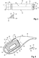
- Nachfolgend wird ein Ausführungsbeispiel der Erfindung anhand einer Zeichnung näher erläutert. Darin zeigen:
- Fig. 1
- in schematischer Darstellung ein Hörinstrument mit einem hohlen Magnetkern, in dem eine wiederaufladbaren Batterie und eine Ladeelektronik angeordnet sind, sowie mit zwei voneinander elektrisch getrennten Spulen, nämlich einer Ladespule und einer Sende- und Empfangsspule (MI-Antenne), die beide um den Magnetkern gewickelt sind,
- Fig. 2
- in Darstellung gemäß
Fig. 1 das dortige Hörinstrument sowie ein externes Ladegerät, das durch induktive Kopplung mit der Ladespule die Batterie des Hörinstruments drahtlos lädt, - Fig. 3
- in Darstellung gemäß
Fig. 1 das dortige Hörinstrument sowie ein weiteres Hörinstruments, das durch induktive Kopplung drahtlos Daten an die MI-Antenne sendet und von dieser empfängt, und - Fig. 4
- in einer schematischen perspektivischen Darstellung den mit der Ladespule und der MI-Antenne bewickelten Magnetkern.
- Einander entsprechende Teile sind in allen Figuren stets mit gleichen Bezugszeichen versehen.
- In
Fig. 1 ist grob schematisch ein Hörinstrument 2 in Form eines (BTE-)Hörgeräts dargestellt. - Das Hörinstrument 2 umfasst ein hinter dem Ohr eines minderhörenden Trägers zu tragendes Gehäuse 4, in welchem als Hauptkomponenten zwei Eingangswandler 6 in Form von Mikrofonen, eine Signalverarbeitungseinheit 8 mit einem digitalen Signalprozessor (z.B. in Form eines ASIC) und/oder einem Mikrocontroller, ein Ausgangswandler 10 in Form eines Hörers sowie eine aufladbare Batterie 12 angeordnet sind. Bei der Batterie 12 handelt es sich um eine Li-Ionen-Batterie. Das Hörinstrument 2 umfasst weiterhin eine (magnetisch) induktive Spule (nachfolgend MI-Antenne 14) zum Senden und/oder Empfangen von magnetischen Wechselsignalen, eine Ladespule 16, eine Ladeelektronik 17 sowie einen Magnetkern 18.
- Im Betrieb des Hörinstruments 2 wird mittels der Eingangswandler 6 ein Schallsignal aus der Umgebung des Hörinstruments 2 aufgenommen und über Signalleitungen 20 als Audiosignal (d.h. als ein die Schallinformation tragendes elektrisches Signal) an die Signalverarbeitungseinheit 8 ausgegeben. Durch die Signalverarbeitungseinheit 8 wird das aufgenommene Audiosignal verarbeitet. Die Signalverarbeitungseinheit 8 umfasst hierzu insbesondere einen Verstärker, durch den das aufgenommene Audiosignal frequenzabhängig verstärkt wird, um die Hörschädigung des Trägers zu kompensieren. Die Signalverarbeitungseinheit 8 gibt über eine Signalleitung 22 ein aus dieser Verarbeitung resultierendes modifiziertes Audiosignal an den Ausgangswandler 10 aus. Dieser wandelt das modifizierte Audiosignal wiederum in ein Schallsignal um. Dieses (gegenüber dem aus der Umgebung aufgenommenen Schall modifizierte) Schallsignal wird von dem Ausgangswandler 10 zunächst durch einen Schallkanal 24 an eine Spitze 26 des Gehäuses 4, und von dort durch einen (nicht explizit dargestellten) Schallschlauch zu einem in das Ohr des Trägers einsetzbaren oder eingesetzten Ohrstück geleitet.
- Die Signalverarbeitungseinheit 8 wird über eine Stromleitung 28 aus der Batterie 12 mit elektrischer Energie versorgt.
- Die Ladespule 16 dient zum Wiederaufladen der Batterie 12 mit elektrischer Energie und kann zu diesem Zweck induktiv mit einem (in
Fig. 2 schematisch angedeuteten) Ladegerät 30 gekoppelt werden. Die Ladespule 16 ist hierzu ausgelegt, von dem Ladegerät 30 ein magnetisches Wechselfeld M1 zu empfangen. Ein durch dieses Wechselfeld M1 in der Ladespule 16 induzierter Ladestrom wird über eine Anschlussleitung 32 (Fig. 1 ) der Ladeelektronik 17 zugeführt, die das Aufladen der Batterie 12 regelt. - Die MI-Antenne 14 ist beispielsweise - wie in
Fig. 3 angedeutet - als induktiver Transceiver zum Datenaustausch mit einem zweiten Hörinstrument 34 ausgebildet, wobei dieses zweite Hörinstrument 34 an dem anderen Ohr des Trägers getragen wird (das zweite Hörinstrument 34 ist vorzugsweise baugleich zu dem Hörinstrument 2 ausgebildet und inFig. 3 lediglich aus Gründen der Übersichtlichkeit kleiner als letzteres dargestellt). Die MI-Antenne 14 ist dabei zum Senden und Empfangen von magnetischen Wechselsignalen M2 im Mega-Hertz-Bereich (z.B. mit einer Frequenz von 3,3 MHz) ausgebildet. Innerhalb des Gehäuses 4 ist die MI-Antenne 14 über eine Signalleitung 36 mit einer (nicht explizit dargestellten) Sende- und Empfangseinheit der Signalverarbeitungseinheit 8 verbunden. - Wie aus den
Fig. 1 und4 erkennbar ist, ist der Magnetkern 18 als zylinderförmiger Hohlkörper aus weichmagnetischem Ferrit gebildet. Er umfasst demnach zwei parallele Stirnflächen 38, die einander entlang einer Achse 40 gegenüberliegen, sowie eine Umfangswand 42, die die Stirnflächen 38 verbindet. In dem gezeigten Ausführungsbeispiel haben die Stirnseiten 38 aus Bauraumgründen eine unregelmäßige Form eines an einer Seite abgeplatteten Ovals. - Der Magnetkern 18 ist insbesondere aus zwei Teilen, nämlich aus einem (durch eine der Stirnflächen 38 und die Umfangswand 42 gebildeten) Topf 44 und einem (durch die zweite Stirnfläche 38 gebildeten) Deckel 46 zusammengesetzt. Alternativ ist der Magnetkern 18, wie in
EP 2 899 830 B1 beschrieben, durch einen Ferritring gebildet, der an beiden Seiten durch aufgesetzte Deckel verschlossen ist. In beiden Fällen ist der Magnetkern 18 allseitig geschlossen. Zumindest Teile der Stromleitung 28 und der Anschlussleitung 32 werden in diesem Fall mit der Batterie 12 bzw. der Ladeelektronik 17 verbunden, bevor der Deckel 46 auf den Topf 44 aufgesetzt wird. Die Stromleitung 28 und die Anschlussleitung 32 werden dabei insbesondere zwischen dem Topf 44 und dem Deckel 46 aus dem Magnetkern 18 herausgeführt. - Die MI-Antenne 14 und die Ladespule 16 sind derart auf den Magnetkern 18 aufgewickelt, dass ihre jeweiligen Spulenachsen 48 und 50 orthogonal (d.h. unter Ausbildung eines Winkels von 90°) aufeinander stehen. Die MI-Antenne 14 ist dabei um die Umfangswand 42 des Magnetkerns 18 herumgewickelt, wodurch ihre Spulenachse 48 parallel zu der Achse 40 des Magnetkerns 18 ausgerichtet ist und mit letzterer insbesondere zusammenfällt. Bevorzugt ist die MI-Antenne 14 dabei mittig auf die Umfangswand 42 aufgewickelt. Sie kann aber auch - wie exemplarisch in
Fig. 4 gezeigt ist - versetzt zu der Mitte der Umfangswand 42 angeordnet sein. Die Ladespule 16 ist dagegen über die Umfangswand 42 und die Stirnseiten 38 auf den Magnetkern 18 aufgewickelt, so dass ihre Spulenachse 50 orthogonal zu der Achse 40 des Magnetkerns 18 ausgerichtet ist. - In beispielhafter Dimensionierung hat der Magnetkern 18 eine (in Richtung seiner Achse 40 gemessene) Höhe von 4 Millimetern, und eine (in Richtung der Spulenachse 50 und somit quer zu der Achse 40 gemessene) Breite von 10 Millimetern. Das Verhältnis der Höhe zu der Breite beträgt somit in diesem Beispiel 1:2,5.
- Die Erfindung wird an dem vorstehend beschriebenen Ausführungsbeispiel besonders deutlich, ist gleichwohl hierauf aber nicht beschränkt. Vielmehr können weitere Ausführungsformen der Erfindung aus den Ansprüchen und der vorstehenden Beschreibung abgeleitet werden.
-
- 2
- Hörinstrument
- 4
- Gehäuse
- 6
- Eingangswandler
- 8
- Signalverarbeitungseinheit
- 10
- Ausgangswandler
- 12
- Batterie
- 14
- MI-Antenne
- 16
- Ladespule
- 17
- Ladeelektronik
- 18
- Magnetkern
- 20
- Signalleitung
- 22
- Signalleitung
- 24
- Schallkanal
- 26
- Spitze
- 28
- Stromleitung
- 30
- Ladegerät
- 32
- Anschlussleitung
- 34
- Hörinstrument
- 36
- Signalleitung
- 38
- Stirnfläche
- 40
- Achse
- 42
- Umfangswand
- 44
- Topf
- 46
- Deckel
- 48
- Spulenachse
- 50
- Spulenachse
- M1
- (magnetisches) Wechselfeld
- M2
- (magnetisches) Wechselsignal
Claims (7)
- Hörinstrument (2)- mit einer wiederaufladbaren Batterie (12),- mit einer Ladespule (16) zum induktiven Empfangen von Energie zum Aufladen der Batterie (12),- mit einer von der Ladespule (16) elektrisch getrennten Sende- und/oder Empfangsspule (14) zum induktiven Senden und/oder Empfangen von Daten, und- mit einem Magnetkern (18), auf den sowohl die Ladespule (16) als auch die Sende- und/oder Empfangsspule (14) aufgewickelt sind.
- Hörinstrument (2) nach Anspruch 1,
wobei die Ladespule (16) und die Sende- und/oder Empfangsspule (14) derart auf dem Magnetkern (18) aufgewickelt sind, dass ihre Spulenachsen (48,50) exakt oder näherungsweise orthogonal zueinander ausgerichtet sind. - Hörinstrument (2) nach Anspruch 1 oder 2,
wobei der Magnetkern (18) als Hohlkörper ausgebildet ist, und wobei die Batterie (12) und/oder eine Elektronikkomponente des Hörinstruments (2), insbesondere eine Ladeelektronik (17), in dem Magnetkern (18) angeordnet sind. - Hörinstrument (2) nach einem der Ansprüche 1 bis 3,
wobei der Magnetkern (18) eine zylindrische Form mit zwei einander entlang einer Achse (40) gegenüberliegenden, parallelen Stirnflächen (38) und einer die Stirnflächen (38) verbindenden Umfangswand (42) aufweist. - Hörinstrument (2) nach Anspruch 4,
wobei der Magnetkern (18) eine entlang seiner Achse (40) gemessene Höhe und eine senkrecht zu seiner Achse gemessene Breite aufweist, und wobei das Verhältnis der Höhe zu der Breite zwischen 1:1 und 1:4, insbesondere etwa 1:2,5 beträgt. - Hörinstrument (2) nach Anspruch 4 oder 5,
wobei eine der beiden Spulen (14) um die Umfangswand (42) gewickelt ist, so dass ihre Spulenachse (48) parallel zu der Achse (40) des Magnetkerns (18) ausgerichtet ist, und wobei die andere Spule (16) über die Stirnflächen (38) und Umfangswand 42) gewickelt ist, so dass ihre Spulenachse (50) orthogonal zu der Achse (40) des Magnetkerns (18) ausgerichtet ist. - Hörinstrument (2) nach einem der Ansprüche 1 bis 6,
wobei der Magnetkern (18) aus einem weichmagnetischen Ferritmaterial besteht.
Applications Claiming Priority (1)
| Application Number | Priority Date | Filing Date | Title |
|---|---|---|---|
| DE102019215843.9A DE102019215843A1 (de) | 2019-10-15 | 2019-10-15 | Hörinstrument |
Publications (1)
| Publication Number | Publication Date |
|---|---|
| EP3809723A1 true EP3809723A1 (de) | 2021-04-21 |
Family
ID=72752821
Family Applications (1)
| Application Number | Title | Priority Date | Filing Date |
|---|---|---|---|
| EP20200360.4A Pending EP3809723A1 (de) | 2019-10-15 | 2020-10-06 | Hörinstrument |
Country Status (4)
| Country | Link |
|---|---|
| US (1) | US11399244B2 (de) |
| EP (1) | EP3809723A1 (de) |
| CN (1) | CN112672263B (de) |
| DE (1) | DE102019215843A1 (de) |
Families Citing this family (3)
| Publication number | Priority date | Publication date | Assignee | Title |
|---|---|---|---|---|
| CN110149583A (zh) * | 2019-05-27 | 2019-08-20 | 深圳市中德听力技术有限公司 | 一种无线充电助听器 |
| EP4152765A1 (de) * | 2021-09-15 | 2023-03-22 | GN Hearing A/S | Drahtlos aufladbare hörvorrichtung |
| WO2025136514A1 (en) * | 2023-12-18 | 2025-06-26 | Apple Inc. | Multi-winding nfc port |
Citations (7)
| Publication number | Priority date | Publication date | Assignee | Title |
|---|---|---|---|---|
| EP2453585A1 (de) * | 2010-11-11 | 2012-05-16 | Nxp B.V. | Nahfeldkommunikationssystem |
| EP2503796B1 (de) * | 2011-03-19 | 2014-05-14 | Starkey Laboratories, Inc. | Hörgerät mit integrierter Spulenbaugruppe |
| US20150214774A1 (en) | 2014-01-24 | 2015-07-30 | Hosiden Corporation | Secondary Coil Module |
| WO2017153274A1 (de) * | 2016-03-07 | 2017-09-14 | Sivantos Pte. Ltd. | Antenne |
| US10020673B2 (en) | 2012-02-17 | 2018-07-10 | Panasonic Intellectual Property Management Co., Ltd. | Electronic device including non-contact charging module and battery |
| US20180286579A1 (en) * | 2017-03-31 | 2018-10-04 | Tdk Corporation | Magnetic coupling device and wireless power transmission system using the same |
| DE202018104183U1 (de) * | 2018-06-08 | 2019-09-12 | Sivantos Pte. Ltd. | Antenne sowie Gerät mit einer solchen Antenne |
Family Cites Families (2)
| Publication number | Priority date | Publication date | Assignee | Title |
|---|---|---|---|---|
| CA3041583A1 (en) * | 2015-10-29 | 2017-05-04 | PogoTec, Inc. | Hearing aid adapted for wireless power reception |
| DE102018221568A1 (de) * | 2018-12-12 | 2020-06-18 | Sivantos Pte. Ltd. | Hörvorrichtung sowie Batteriemodul zur Anordnung in einer Hörvorrichtung |
-
2019
- 2019-10-15 DE DE102019215843.9A patent/DE102019215843A1/de active Pending
-
2020
- 2020-10-06 EP EP20200360.4A patent/EP3809723A1/de active Pending
- 2020-10-14 CN CN202011094996.9A patent/CN112672263B/zh active Active
- 2020-10-14 US US17/070,007 patent/US11399244B2/en active Active
Patent Citations (8)
| Publication number | Priority date | Publication date | Assignee | Title |
|---|---|---|---|---|
| EP2453585A1 (de) * | 2010-11-11 | 2012-05-16 | Nxp B.V. | Nahfeldkommunikationssystem |
| EP2503796B1 (de) * | 2011-03-19 | 2014-05-14 | Starkey Laboratories, Inc. | Hörgerät mit integrierter Spulenbaugruppe |
| US10020673B2 (en) | 2012-02-17 | 2018-07-10 | Panasonic Intellectual Property Management Co., Ltd. | Electronic device including non-contact charging module and battery |
| US20150214774A1 (en) | 2014-01-24 | 2015-07-30 | Hosiden Corporation | Secondary Coil Module |
| EP2899830B1 (de) | 2014-01-24 | 2017-08-30 | Hosiden Corporation | Sekundärspulenmodul |
| WO2017153274A1 (de) * | 2016-03-07 | 2017-09-14 | Sivantos Pte. Ltd. | Antenne |
| US20180286579A1 (en) * | 2017-03-31 | 2018-10-04 | Tdk Corporation | Magnetic coupling device and wireless power transmission system using the same |
| DE202018104183U1 (de) * | 2018-06-08 | 2019-09-12 | Sivantos Pte. Ltd. | Antenne sowie Gerät mit einer solchen Antenne |
Also Published As
| Publication number | Publication date |
|---|---|
| US20210112348A1 (en) | 2021-04-15 |
| DE102019215843A1 (de) | 2021-04-15 |
| CN112672263B (zh) | 2022-09-20 |
| US11399244B2 (en) | 2022-07-26 |
| CN112672263A (zh) | 2021-04-16 |
Similar Documents
| Publication | Publication Date | Title |
|---|---|---|
| EP1962557B1 (de) | Hörvorrichtung mit einem speziellen Energieaufnahmesystem und entsprechendes Verfahren | |
| EP2811761B1 (de) | Antenneneinrichtung für Hörinstrumente | |
| EP3413587B1 (de) | Hörgerät, insbesondere hinter-dem-ohr-hörhilfegerät | |
| DE10228157B3 (de) | Hörgerätesystem mit einem Hörgerät und einer externen Prozessoreinheit | |
| EP3491846B1 (de) | Hörhilfegerät und hörhilfevorrichtung | |
| EP2894880B1 (de) | Antenneneinrichtung für Hörinstrumente | |
| US10966036B2 (en) | Hearing device including an external antenna and an internal parasitic element | |
| WO2019219972A1 (de) | Mehrteiliges, tief im gehörgang platziertes trommelfell-kontakt-hörgerät | |
| DE102010021173A1 (de) | Hörvorrichtung mit passiver, tief im Gehörgang sitzender Einheit | |
| EP3343954B1 (de) | Ein hörgerät mit einem externen antenna-teil sowie einem internen antenna-teil | |
| EP2104377A2 (de) | Hörsystem mit Teilbandsignalaustausch und entsprechendes Verfahren | |
| DE102019215843A1 (de) | Hörinstrument | |
| EP1651006A2 (de) | Hörhilfegerät mit einer Leitungsschleife zur Kompensation induktiver Störfelder | |
| EP3614494B1 (de) | Performante magnetisch induktive antenne für ein hörinstrument | |
| DE102005006404B3 (de) | Modulares Hörgerätesystem | |
| EP2053878B1 (de) | Hörvorrichtung mit Nutzung eines induktiven Schaltreglers als Funksender | |
| EP2793488B1 (de) | Binaurale Mikrofonanpassung mittels der eigenen Stimme | |
| EP3739906B1 (de) | Hörinstrument | |
| DE102017012195B4 (de) | Hörgerät, insbesondere Hinter-dem-Ohr-Hörhilfegerät | |
| DE102004050616B3 (de) | Hörhilfe mit Signalkopplung und entsprechendes Verfahren | |
| DE102011075739A1 (de) | Kommunikationssystem mit Hörvorrichtung und Telefon sowie Betriebsverfahren | |
| US20230197094A1 (en) | Electronic device and method for obtaining a user's speech in a first sound signal | |
| DE102014219017A1 (de) | Hörinstrument mit Energieversorgungseinrichtung und Hörinstrumentensystem mit Energieversorgungseinrichtung | |
| EP4607696A1 (de) | Hörgerät | |
| EP2885926A1 (de) | Hörsystem sowie übertragungsverfahren |
Legal Events
| Date | Code | Title | Description |
|---|---|---|---|
| PUAI | Public reference made under article 153(3) epc to a published international application that has entered the european phase |
Free format text: ORIGINAL CODE: 0009012 |
|
| STAA | Information on the status of an ep patent application or granted ep patent |
Free format text: STATUS: THE APPLICATION HAS BEEN PUBLISHED |
|
| AK | Designated contracting states |
Kind code of ref document: A1 Designated state(s): AL AT BE BG CH CY CZ DE DK EE ES FI FR GB GR HR HU IE IS IT LI LT LU LV MC MK MT NL NO PL PT RO RS SE SI SK SM TR |
|
| AX | Request for extension of the european patent |
Extension state: BA ME |
|
| STAA | Information on the status of an ep patent application or granted ep patent |
Free format text: STATUS: REQUEST FOR EXAMINATION WAS MADE |
|
| 17P | Request for examination filed |
Effective date: 20211020 |
|
| RBV | Designated contracting states (corrected) |
Designated state(s): AL AT BE BG CH CY CZ DE DK EE ES FI FR GB GR HR HU IE IS IT LI LT LU LV MC MK MT NL NO PL PT RO RS SE SI SK SM TR |
|
| STAA | Information on the status of an ep patent application or granted ep patent |
Free format text: STATUS: EXAMINATION IS IN PROGRESS |
|
| 17Q | First examination report despatched |
Effective date: 20230126 |