EP3809679A1 - Receiver module and terminal device - Google Patents
Receiver module and terminal device Download PDFInfo
- Publication number
- EP3809679A1 EP3809679A1 EP19833594.5A EP19833594A EP3809679A1 EP 3809679 A1 EP3809679 A1 EP 3809679A1 EP 19833594 A EP19833594 A EP 19833594A EP 3809679 A1 EP3809679 A1 EP 3809679A1
- Authority
- EP
- European Patent Office
- Prior art keywords
- sound
- soundproofing
- assembly
- emitting hole
- drive
- Prior art date
- Legal status (The legal status is an assumption and is not a legal conclusion. Google has not performed a legal analysis and makes no representation as to the accuracy of the status listed.)
- Granted
Links
Images



Classifications
-
- G—PHYSICS
- G06—COMPUTING OR CALCULATING; COUNTING
- G06F—ELECTRIC DIGITAL DATA PROCESSING
- G06F1/00—Details not covered by groups G06F3/00 - G06F13/00 and G06F21/00
- G06F1/16—Constructional details or arrangements
- G06F1/1613—Constructional details or arrangements for portable computers
- G06F1/1633—Constructional details or arrangements of portable computers not specific to the type of enclosures covered by groups G06F1/1615 - G06F1/1626
- G06F1/1684—Constructional details or arrangements related to integrated I/O peripherals not covered by groups G06F1/1635 - G06F1/1675
- G06F1/1698—Constructional details or arrangements related to integrated I/O peripherals not covered by groups G06F1/1635 - G06F1/1675 the I/O peripheral being a sending/receiving arrangement to establish a cordless communication link, e.g. radio or infrared link, integrated cellular phone
-
- H—ELECTRICITY
- H04—ELECTRIC COMMUNICATION TECHNIQUE
- H04R—LOUDSPEAKERS, MICROPHONES, GRAMOPHONE PICK-UPS OR LIKE ACOUSTIC ELECTROMECHANICAL TRANSDUCERS; ELECTRIC HEARING AIDS; PUBLIC ADDRESS SYSTEMS
- H04R1/00—Details of transducers, loudspeakers or microphones
- H04R1/20—Arrangements for obtaining desired frequency or directional characteristics
- H04R1/22—Arrangements for obtaining desired frequency or directional characteristics for obtaining desired frequency characteristic only
- H04R1/28—Transducer mountings or enclosures modified by provision of mechanical or acoustic impedances, e.g. resonator, damping means
- H04R1/2869—Reduction of undesired resonances, i.e. standing waves within enclosure, or of undesired vibrations, i.e. of the enclosure itself
- H04R1/2876—Reduction of undesired resonances, i.e. standing waves within enclosure, or of undesired vibrations, i.e. of the enclosure itself by means of damping material, e.g. as cladding
- H04R1/288—Reduction of undesired resonances, i.e. standing waves within enclosure, or of undesired vibrations, i.e. of the enclosure itself by means of damping material, e.g. as cladding for loudspeaker transducers
-
- G—PHYSICS
- G06—COMPUTING OR CALCULATING; COUNTING
- G06F—ELECTRIC DIGITAL DATA PROCESSING
- G06F1/00—Details not covered by groups G06F3/00 - G06F13/00 and G06F21/00
- G06F1/16—Constructional details or arrangements
- G06F1/1613—Constructional details or arrangements for portable computers
- G06F1/1633—Constructional details or arrangements of portable computers not specific to the type of enclosures covered by groups G06F1/1615 - G06F1/1626
- G06F1/1656—Details related to functional adaptations of the enclosure, e.g. to provide protection against EMI, shock, water, or to host detachable peripherals like a mouse or removable expansions units like PCMCIA cards, or to provide access to internal components for maintenance or to removable storage supports like CDs or DVDs, or to mechanically mount accessories
-
- G—PHYSICS
- G06—COMPUTING OR CALCULATING; COUNTING
- G06F—ELECTRIC DIGITAL DATA PROCESSING
- G06F1/00—Details not covered by groups G06F3/00 - G06F13/00 and G06F21/00
- G06F1/16—Constructional details or arrangements
- G06F1/1613—Constructional details or arrangements for portable computers
- G06F1/1633—Constructional details or arrangements of portable computers not specific to the type of enclosures covered by groups G06F1/1615 - G06F1/1626
- G06F1/1684—Constructional details or arrangements related to integrated I/O peripherals not covered by groups G06F1/1635 - G06F1/1675
-
- G—PHYSICS
- G06—COMPUTING OR CALCULATING; COUNTING
- G06F—ELECTRIC DIGITAL DATA PROCESSING
- G06F1/00—Details not covered by groups G06F3/00 - G06F13/00 and G06F21/00
- G06F1/16—Constructional details or arrangements
- G06F1/1613—Constructional details or arrangements for portable computers
- G06F1/1633—Constructional details or arrangements of portable computers not specific to the type of enclosures covered by groups G06F1/1615 - G06F1/1626
- G06F1/1684—Constructional details or arrangements related to integrated I/O peripherals not covered by groups G06F1/1635 - G06F1/1675
- G06F1/1688—Constructional details or arrangements related to integrated I/O peripherals not covered by groups G06F1/1635 - G06F1/1675 the I/O peripheral being integrated loudspeakers
-
- H—ELECTRICITY
- H04—ELECTRIC COMMUNICATION TECHNIQUE
- H04B—TRANSMISSION
- H04B1/00—Details of transmission systems, not covered by a single one of groups H04B3/00 - H04B13/00; Details of transmission systems not characterised by the medium used for transmission
- H04B1/06—Receivers
- H04B1/08—Constructional details, e.g. cabinet
- H04B1/086—Portable receivers
-
- H—ELECTRICITY
- H04—ELECTRIC COMMUNICATION TECHNIQUE
- H04M—TELEPHONIC COMMUNICATION
- H04M1/00—Substation equipment, e.g. for use by subscribers
- H04M1/02—Constructional features of telephone sets
- H04M1/0202—Portable telephone sets, e.g. cordless phones, mobile phones or bar type handsets
- H04M1/026—Details of the structure or mounting of specific components
-
- H—ELECTRICITY
- H04—ELECTRIC COMMUNICATION TECHNIQUE
- H04M—TELEPHONIC COMMUNICATION
- H04M1/00—Substation equipment, e.g. for use by subscribers
- H04M1/02—Constructional features of telephone sets
- H04M1/03—Constructional features of telephone transmitters or receivers, e.g. telephone hand-sets
-
- H—ELECTRICITY
- H04—ELECTRIC COMMUNICATION TECHNIQUE
- H04R—LOUDSPEAKERS, MICROPHONES, GRAMOPHONE PICK-UPS OR LIKE ACOUSTIC ELECTROMECHANICAL TRANSDUCERS; ELECTRIC HEARING AIDS; PUBLIC ADDRESS SYSTEMS
- H04R1/00—Details of transducers, loudspeakers or microphones
- H04R1/02—Casings; Cabinets ; Supports therefor; Mountings therein
- H04R1/025—Arrangements for fixing loudspeaker transducers, e.g. in a box, furniture
-
- H—ELECTRICITY
- H04—ELECTRIC COMMUNICATION TECHNIQUE
- H04R—LOUDSPEAKERS, MICROPHONES, GRAMOPHONE PICK-UPS OR LIKE ACOUSTIC ELECTROMECHANICAL TRANSDUCERS; ELECTRIC HEARING AIDS; PUBLIC ADDRESS SYSTEMS
- H04R1/00—Details of transducers, loudspeakers or microphones
- H04R1/20—Arrangements for obtaining desired frequency or directional characteristics
- H04R1/32—Arrangements for obtaining desired frequency or directional characteristics for obtaining desired directional characteristic only
- H04R1/323—Arrangements for obtaining desired frequency or directional characteristics for obtaining desired directional characteristic only for loudspeakers
-
- H—ELECTRICITY
- H04—ELECTRIC COMMUNICATION TECHNIQUE
- H04M—TELEPHONIC COMMUNICATION
- H04M1/00—Substation equipment, e.g. for use by subscribers
- H04M1/02—Constructional features of telephone sets
- H04M1/0202—Portable telephone sets, e.g. cordless phones, mobile phones or bar type handsets
- H04M1/0279—Improving the user comfort or ergonomics
-
- H—ELECTRICITY
- H04—ELECTRIC COMMUNICATION TECHNIQUE
- H04R—LOUDSPEAKERS, MICROPHONES, GRAMOPHONE PICK-UPS OR LIKE ACOUSTIC ELECTROMECHANICAL TRANSDUCERS; ELECTRIC HEARING AIDS; PUBLIC ADDRESS SYSTEMS
- H04R2499/00—Aspects covered by H04R or H04S not otherwise provided for in their subgroups
- H04R2499/10—General applications
- H04R2499/11—Transducers incorporated or for use in hand-held devices, e.g. mobile phones, PDA's, camera's
Definitions
- two receivers are disposed inside a dual-panel terminal device and the two receivers are in one-to-one correspondence to the two panels.
- the receiver corresponding to that panel is started to work.
- a receiver module includes a housing, a receiver, a drive assembly and a soundproofing assembly, where the housing is internally provided with an accommodating space, the receiver is arranged in the accommodating space, and the housing and the receiver fit together to form a sound cavity, a sound-emitting side of the receiver facing towards the sound cavity; the housing is provided with a first sound-emitting hole and a second sound-emitting hole; the drive assembly and the soundproofing assembly are connected, and the drive assembly is configured to drive the soundproofing assembly to be in a first state or a second state; where when the soundproofing assembly is in the first state, the second sound-emitting hole is in communication with the sound cavity, and the soundproofing assembly blocks off the first sound-emitting hole from the sound cavity; and when the soundproofing assembly is in the second state, the first sound-emitting hole is in communication with the sound cavity, and the soundproofing assembly blocks off the second sound-emitting hole from the sound cavity.
- the drive assembly 30 can drive the first soundproofing piece 41 to rotate along the inner wall of the sound cavity 11.
- first soundproofing piece 41 rotates to a first angle, that is, when the soundproofing assembly 40 is in the first state, as shown in FIG. 1
- the first soundproofing piece 41 blocks off communication between the first sound-emitting hole 12 and the sound cavity 11, and the second sound-emitting hole 13 is in communication with the sound cavity 11 at this moment; and when the first soundproofing piece 41 rotates to a second angle, that is, the soundproofing assembly 40 is in the second state, as shown in FIG.
- the inner wall of the sound cavity 11 may be a surface along which the first soundproofing assembly 40 rotates, or the inner wall of the sound cavity 11 may be a cylindrical surface or all or a part of a spherical surface, or the like.
- the sound cavity 11 may also be set as a cylindrical cavity, a spherical cavity, or the like. This is not limited herein.
- the arc-shaped edge of the fan-shaped connecting plate 412 is connected to the soundproofing block 411 (such as a soundproofing block made of sealing foam) and the peripheral direction of the fan-shaped connecting plate 412 is the same as the rotating direction of the soundproofing block 411. Therefore, when the soundproofing block 411 rotates, the fan-shaped connecting plate 412 can provide large and uniform support force for the soundproofing block 411, enabling the soundproofing block 411 to be more tightly laminated with the inner wall of the sound cavity 11, and enabling the first soundproofing piece 41 to better block off the first sound-emitting hole 12 from the sound cavity 11, and the second sound-emitting hole 13 from the sound cavity 11.
- the soundproofing block 411 such as a soundproofing block made of sealing foam
- the first drive motor 311 can drive the second soundproofing piece 42 to move along the transmission shaft 32
- the second drive motor 312 can drive the third soundproofing piece 43 to move along the transmission shaft 32.
- the soundproofing assembly 40 moves to the first position, that is, the soundproofing assembly 40 is in the first state, as shown in FIG.
- the soundproofing assembly 40 may be any structure that can block off communication between the first sound-emitting hole 12 and the sound cavity 11 and communication between the second sound-emitting hole 13 and the sound cavity 11.
- the soundproofing assembly 40 is a soundproofing assembly 40 formed by a sealing material (such as sealing foam), further improving the sealing performance of the soundproofing assembly 40, and improving the sound effect and waterproof, dustproof and other performance of the receiver module.
Landscapes
- Engineering & Computer Science (AREA)
- Computer Hardware Design (AREA)
- Theoretical Computer Science (AREA)
- Physics & Mathematics (AREA)
- Signal Processing (AREA)
- General Engineering & Computer Science (AREA)
- Human Computer Interaction (AREA)
- General Physics & Mathematics (AREA)
- Acoustics & Sound (AREA)
- Health & Medical Sciences (AREA)
- Otolaryngology (AREA)
- Computer Networks & Wireless Communication (AREA)
- Telephone Set Structure (AREA)
- Toys (AREA)
- Burglar Alarm Systems (AREA)
- Input Circuits Of Receivers And Coupling Of Receivers And Audio Equipment (AREA)
Abstract
Description
- The application claims priority to Chinese Patent Application No.
201810751694.0 - Embodiments of this disclosure relate to the field of communications technologies, and in particular, to a receiver module and a terminal device.
- As communication technologies develop, smartphones, tablet computers and other terminal devices are becoming increasingly popular and have become an indispensable part in people's daily routines. People also have increasing requirements on terminal devices, especially on voice call of terminal devices. In some cases, a user may require that two different positions of a terminal device should each be provided with one receiver, such that the receivers at different positions are used in different scenarios to produce sound, so as to implement calls.
- For example, two receivers are disposed inside a dual-panel terminal device and the two receivers are in one-to-one correspondence to the two panels. When a user uses one panel for a call, the receiver corresponding to that panel is started to work.
- However, in a case in which two receivers are mounted in a terminal device, limitations for mounting other components on a main circuit board inside the terminal device will be thus caused because both the receivers need to respectively occupy mounting space on the main circuit board inside the dual-panel terminal device. It can be seen that at present, to enable a terminal device to produce sound at two different positions, there exists a problem of occupying large mounting space on a main circuit board due to mounting of two receivers.
- According to a first aspect, an embodiment of this disclosure provides a receiver module, including a housing, a receiver, a drive assembly and a soundproofing assembly, where
the housing is internally provided with an accommodating space, the receiver is arranged in the accommodating space, and the housing and the receiver fit together to form a sound cavity, a sound-emitting side of the receiver facing towards the sound cavity;
the housing is provided with a first sound-emitting hole and a second sound-emitting hole; and
the drive assembly and the soundproofing assembly are connected and the drive assembly is configured to drive the soundproofing assembly to be in a first state or a second state, where
when the soundproofing assembly is in the first state, the second sound-emitting hole is in communication with the sound cavity and the soundproofing assembly blocks off the first sound-emitting hole from the sound cavity; and
when the soundproofing assembly is in the second state, the first sound-emitting hole is in communication with the sound cavity and the soundproofing assembly blocks off the second sound-emitting hole from the sound cavity. - According to a second aspect, an embodiment of this disclosure further provides a terminal device, including the foregoing receiver module.
- In the embodiments of this disclosure, a receiver module includes a housing, a receiver, a drive assembly and a soundproofing assembly, where the housing is internally provided with an accommodating space, the receiver is arranged in the accommodating space, and the housing and the receiver fit together to form a sound cavity, a sound-emitting side of the receiver facing towards the sound cavity; the housing is provided with a first sound-emitting hole and a second sound-emitting hole; the drive assembly and the soundproofing assembly are connected, and the drive assembly is configured to drive the soundproofing assembly to be in a first state or a second state; where when the soundproofing assembly is in the first state, the second sound-emitting hole is in communication with the sound cavity, and the soundproofing assembly blocks off the first sound-emitting hole from the sound cavity; and when the soundproofing assembly is in the second state, the first sound-emitting hole is in communication with the sound cavity, and the soundproofing assembly blocks off the second sound-emitting hole from the sound cavity.
- To describe the technical solutions in embodiments of this disclosure more clearly, the following briefly describes the accompanying drawings required for describing the embodiments of this disclosure. Obviously, the accompanying drawings described below are merely some embodiments of this disclosure. A person of ordinary skill in the art may derive other drawings from these accompanying drawings without creative efforts.
-
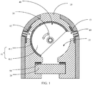
FIG. 1 is a first schematic diagram of a cross-section structure of a receiver module according to an embodiment of this disclosure; -
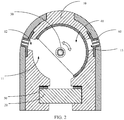
FIG. 2 is a second schematic diagram of a cross-section structure of a receiver module according to an embodiment of this disclosure; -
FIG. 3 is a third schematic diagram of a cross-section structure of a receiver module according to an embodiment of this disclosure; -
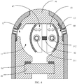
FIG. 4 is a fourth schematic diagram of a cross-section structure of a receiver module according to an embodiment of this disclosure; -
FIG. 5 is a fifth schematic diagram of a cross-section structure of a receiver module according to an embodiment of this disclosure; -
FIG. 6 is a sixth schematic diagram of a cross-section structure of a receiver module according to an embodiment of this disclosure; and -
FIG. 7 is a seventh schematic diagram of a cross-section structure of a receiver module according to an embodiment of this disclosure. - The following clearly and completely describes the technical solutions in the embodiments of this disclosure with reference to the accompanying drawings. Apparently, the described embodiments are merely some rather than all of the embodiments of this disclosure. Based on the embodiments of this disclosure, all other embodiments derived by a person of ordinary skill in the art without creative efforts belong to the protection scope of this disclosure.
- Referring to
FIG. 1 andFIG. 2 , a receiver module includes ahousing 10, areceiver 20, adrive assembly 30 and asoundproofing assembly 40. - The
housing 10 is internally provided with an accommodating space, thereceiver 20 is arranged in the accommodating space, and thehousing 10 and thereceiver 20 fit together to form asound cavity 11, a sound-emitting side of thereceiver 20 facing towards thesound cavity 11. - The
housing 10 is provided with a first sound-emittinghole 12 and a second sound-emittinghole 13. - The
drive assembly 30 and thesoundproofing assembly 40 are connected, and thedrive assembly 30 is configured to drive thesoundproofing assembly 40 to be in a first state or a second state. - When the
soundproofing assembly 40 is in the first state, the second sound-emitting hole 13 is in communication with thesound cavity 11, and thesoundproofing assembly 40 blocks off the first sound-emitting hole 12 from thesound cavity 11. - When the
soundproofing assembly 40 is in the second state, the first sound-emitting hole 12 is in communication with thesound cavity 11, and thesoundproofing assembly 40 blocks off the second sound-emitting hole 13 from thesound cavity 11. - In this embodiment of this disclosure, when the
soundproofing assembly 40 is in the first state, the second sound-emitting hole 13 is in communication with thesound cavity 11, and thesoundproofing assembly 40 blocks off the first sound-emittinghole 12 from thesound cavity 11, such that sound produced by thereceiver 20 is emitted via the second sound-emittinghole 13 by thesound cavity 11; and when thesoundproofing assembly 40 is in the second state, the first sound-emitting hole 12 is in communication with thesound cavity 11, and thesoundproofing assembly 40 blocks off the second sound-emitting hole 13 from thesound cavity 11, such that sound provided by thereceiver 20 is emitted via the first sound-emittinghole 12 by thesound cavity 11. In this way, in different application scenarios, the receiver module can conduct sound produced by thereceiver 20 respectively via the first sound-emitting hole 12 and the second sound-emitting hole 13. - It should be noted that the
foregoing housing 10 may be a part or all of a shell of a terminal device mounted with the foregoing receiver module, or may be a structure that is independently set and does not belong to the shell of the terminal device, which is not limited herein. - The foregoing first sound-emitting
hole 12 and second sound-emittinghole 13 are made into different positions on thehousing 10, and the first sound-emittinghole 12 and the second sound-emittinghole 13 are each in communication with thesound cavity 11 and an exterior of thehousing 10, such that the first sound-emittinghole 12 and the second sound-emittinghole 13 can conduct sound inside thesound cavity 11 to the exterior of thehousing 10. - Herein, the positions of the first sound-emitting
hole 12 and the second sound-emittinghole 13 made on thehousing 10 may be set based on use scenarios of the terminal device by a user. For example, if thehousing 10 is the shell of the terminal device, the first sound-emittinghole 12 and the second sound-emittinghole 13 can be respectively made into the top and the bottom of a same side, so that calls can be normally made when the terminal device is in upright and inverted states. - Alternatively, in a specific embodiment of this disclosure, the first sound-
emitting hole 12 and the second sound-emittinghole 13 are respectively made into two side faces of thehousing 10 facing away from each other, so as to enable the receiver module to produce sound in two opposite directions. For example, when a dual-panel terminal device is provided with the foregoing receiver module, the first sound-emitting hole 12 is made into a first panel on a first side face of thehousing 10, the second sound-emitting hole 13 is made into the first panel on a second side face of thehousing 10, and the first side face and the second side face are two side faces of thehousing 10 facing away from each other. In this way, when the user makes a call while the first panel of the terminal device is in work, the receiver module produces sound via the first sound-emitting hole 12; and when the user makes a call while the second panel is in work, the receiver module produces sound via the second sound-emitting hole 13. - In this embodiment of this disclosure, the
receiver 20 is arranged in the accommodating space of thehousing 10, and thehousing 10 and thereceiver 20 fit together to form thesound cavity 11, which may be an accommodating space including a clamping slot, into which thereceiver 20 is clamped. Alternatively, thereceiver 20 may be connected to thehousing 10 through bonding or other manners. This is not limited herein. - Additionally, the sound-emitting side of the
receiver 20 faces towards thesound cavity 11, to ensure that sound produced by thereceiver 20 is conducted into thesound cavity 11. In a specific embodiment of this disclosure, asealing layer 50 is disposed at a joint of the sound-emitting side of thereceiver 20 with the accommodating space. Thesealing layer 50 can seal a joint between thereceiver 20 and the inner wall of thehousing 10, so that thesound cavity 11 becomes a closed space, thereby improving a sounding effect of the receiver module. - The
sealing layer 50 may include a dustproof layer and a sealing material layer (such as a sealing foam layer) so as to improve tightness of thesound cavity 11 and implement dustproof, waterproof and other performance of thesound cavity 11. - In this embodiment of this disclosure, the
drive assembly 30 is configured to drive thesoundproofing assembly 40 to be in a first state or a second state, and may be partially or wholly arranged in thesound cavity 11. For example, if thedrive assembly 30 is a micro motor, it may be wholly accommodated in thesound cavity 11; or a rotating shaft of the motor may extend into thesound cavity 11 and be connected to thesoundproofing assembly 40, or the like. - Additionally, the
soundproofing assembly 40 may be any assembly in the first state or the second state. To be specific, driven by thedrive assembly 30, thesoundproofing assembly 40 can block off communication between the first sound-emitting hole 12 and thesound cavity 11 and communication between the second sound-emitting hole 13 and thesound cavity 11. - In a specific embodiment of this disclosure, as shown in
FIG. 1 andFIG. 2 , thesoundproofing assembly 40 includes afirst soundproofing piece 41 laminated with an inner wall of thesound cavity 11; and
thedrive assembly 30 drives thefirst soundproofing piece 41 to rotate along the inner wall of thesound cavity 11. - The
drive assembly 30 can drive thefirst soundproofing piece 41 to rotate along the inner wall of thesound cavity 11. To be specific, when thefirst soundproofing piece 41 rotates to a first angle, that is, when the soundproofingassembly 40 is in the first state, as shown inFIG. 1 , thefirst soundproofing piece 41 blocks off communication between the first sound-emittinghole 12 and thesound cavity 11, and the second sound-emittinghole 13 is in communication with thesound cavity 11 at this moment; and when thefirst soundproofing piece 41 rotates to a second angle, that is, the soundproofingassembly 40 is in the second state, as shown inFIG. 2 , asecond soundproofing piece 42 blocks off communication between the first sound-emittinghole 12 and thesound cavity 11, and the first sound-emittinghole 12 is in communication with thesound cavity 11 at this moment. In this way, thefirst soundproofing piece 41 can move simply and is easy to be driven. Additionally, since thefirst soundproofing piece 41 is always closely laminated with the inner wall of thesound cavity 11, the soundproofing effect can be further improved. - It should be noted that the inner wall of the
sound cavity 11 may be a surface along which thefirst soundproofing assembly 40 rotates, or the inner wall of thesound cavity 11 may be a cylindrical surface or all or a part of a spherical surface, or the like. Thesound cavity 11 may also be set as a cylindrical cavity, a spherical cavity, or the like. This is not limited herein. - Additionally, the
first soundproofing piece 41 is driven by thedrive assembly 30 to rotate and thefirst soundproofing piece 41 can be closely laminated with the inner wall of thesound cavity 11. For example, thefirst soundproofing piece 41 can include a soundproofing material layer and a plurality of support rods and the soundproofing material layer can bear some stress, then the plurality of support rods support thefirst soundproofing piece 41 at a plurality of position points and thedrive assembly 30 drives the soundproofing material layer to rotate via the plurality of support rods. - Alternatively, in a specific embodiment of this disclosure, the
first soundproofing piece 41 includes asoundproofing block 411 and a fan-shaped connectingplate 412, an arc-shaped edge of the fan-shaped connectingplate 412 being connected to thesoundproofing block 411; thesoundproofing block 411 is laminated with the inner wall of thesound cavity 11, and thedrive assembly 30 drives thesoundproofing block 411 through the fan-shaped connectingplate 412 to rotate along the inner wall of thesound cavity 11; and a peripheral direction of the fan-shaped connectingplate 412 is the same as a rotating direction of thesoundproofing block 411. - In this implementation, the arc-shaped edge of the fan-shaped connecting
plate 412 is connected to the soundproofing block 411 (such as a soundproofing block made of sealing foam) and the peripheral direction of the fan-shaped connectingplate 412 is the same as the rotating direction of thesoundproofing block 411. Therefore, when thesoundproofing block 411 rotates, the fan-shaped connectingplate 412 can provide large and uniform support force for thesoundproofing block 411, enabling thesoundproofing block 411 to be more tightly laminated with the inner wall of thesound cavity 11, and enabling thefirst soundproofing piece 41 to better block off the first sound-emittinghole 12 from thesound cavity 11, and the second sound-emittinghole 13 from thesound cavity 11. - The
drive assembly 30 drives thesoundproofing block 411 to rotate through the fan-shaped connectingplate 412. The fan-shaped connectingplate 412 may be connected to a rotation shaft of thedrive assembly 30. When the rotation shaft of thedrive assembly 30 rotates, the fan-shaped connectingplate 412 drives thesoundproofing piece 411 to rotate under the effect of the rotation shaft. Moreover, a position at which the rotation shaft and the fan-shaped connectingplate 412 are connected can be set depending on actual requirements. This is not limited herein. - In a specific embodiment of this disclosure, as shown in
FIG. 3 andFIG. 4 , thedrive assembly 30 includes adrive piece 31 and atransmission shaft 32, thedrive piece 31 and the soundproofingassembly 40 being connected and thedrive piece 31 driving the soundproofingassembly 40 to rotate along thetransmission shaft 32. - When the soundproofing
assembly 40 moves to a first position of thetransmission shaft 32, the soundproofingassembly 40 is in the first state. - When the soundproofing
assembly 40 moves to a second position of thetransmission shaft 32, the soundproofingassembly 40 is in the second state. - Herein, the
drive piece 31 can drive the soundproofingassembly 40 to move along thetransmission shaft 32, so that the soundproofingassembly 40 blocks off communication between the first sound-emittinghole 12 and thesound cavity 11 and communication between the second sound-emittinghole 13 and thesound cavity 11 when moving to different positions on thetransmission shaft 32. The movement manner is simple and easy to implement, making the structure of the receiver module simple. - It should be noted that the
drive assembly 30 may be any structure that can drive the soundproofingassembly 40 to move along itstransmission shaft 32. For example, thedrive assembly 30 includes a lead screw and a lead screw stepping motor movably connected to the lead screw. The soundproofingassembly 40 is connected to the lead screw stepping motor and the lead screen stepping motor drives the soundproofingassembly 40 to move left and right along the lead screw, and so on. - Additionally, the soundproofing
assembly 40 is driven by thedrive piece 31 to move to the first position and the second position along thetransmission shaft 32, and it may be an overall structure driven to move by one drive motor (such as a lead screw stepping motor). Alternatively, in a specific embodiment of this disclosure, thedrive piece 31 includes afirst drive motor 311 and asecond drive motor 312, and the soundproofingassembly 40 includes asecond soundproofing piece 42 and athird soundproofing piece 43. - The
second soundproofing piece 42 is connected to thefirst drive motor 311, thefirst drive motor 311 being configured to drive thesecond soundproofing piece 42 to move along thetransmission shaft 32. - The
third soundproofing piece 43 is connected to thesecond drive motor 312, thesecond drive motor 312 being configured to drive thethird soundproofing piece 43 to move along thetransmission shaft 32. - In this implementation, the
first drive motor 311 can drive thesecond soundproofing piece 42 to move along thetransmission shaft 32, and thesecond drive motor 312 can drive thethird soundproofing piece 43 to move along thetransmission shaft 32. In this way, when thefirst drive motor 311 drives thesecond soundproofing piece 42 to laminate with the inner wall of thesound cavity 11 and thesecond drive motor 312 drives thethird soundproofing piece 43 to be spaced apart from the inner wall of thesound cavity 11, the soundproofingassembly 40 moves to the first position, that is, the soundproofingassembly 40 is in the first state, as shown inFIG. 3 ; and when thefirst drive motor 311 drives thesecond soundproofing piece 42 to be spaced apart from the inner wall of thesound cavity 11 and thesecond drive motor 312 drives thethird soundproofing piece 43 to laminate with the inner wall of thesound cavity 11, the soundproofingassembly 40 moves to the second position, that is, the soundproofingassembly 40 is in the second state, as shown inFIG. 4 . This supports more flexible movement manners for the soundproofingassembly 40 and allows more diverse structures of the receiver module. - It should be noted that the
first drive motor 311 drives thesecond soundproofing piece 42 to move and thesecond drive motor 312 drives thethird soundproofing piece 43 to move, which may be that thesecond soundproofing piece 42 and thethird soundproofing piece 43 move along asame transmission shaft 32; or thedrive assembly 30 is provided with twotransmission shafts 32 and thesecond soundproofing piece 42 and thethird soundproofing piece 43 are driven by the corresponding drive motors to move alongdifferent transmission shafts 32. This is not limited herein. - Additionally, in a case in which the
soundproofing assembly 40 moves along thetransmission shaft 32, the inner wall of thesound cavity 11 with which thesoundproofing assembly 40 comes into contact may be set as a flat contact surface. For example, when thesound cavity 11 is set as a rectangular cavity and the first sound-emittinghole 12 and the second sound-emittinghole 13 are each made into any one inner wall of the rectangular cavity; or the inner wall of thesound cavity 11 with which thesoundproofing assembly 40 comes into contact may be set as an arc-shaped inner wall, such as thesound cavity 11 being a cylindrical cavity or a spherical cavity, such that the soundproofingassembly 40 can come into closer contact with the inner wall of thesound cavity 11, further improving the soundproofing effect. - It should be noted that the structures of the
second soundproofing piece 42 and thethird soundproofing piece 43 may be the same as or differ from the composition structure of thefirst soundproofing piece 41. This is not limited herein. - Certainly, the foregoing embodiments only describe the case in which the
soundproofing assembly 40 is driven by thedrive assembly 30 to be in the first state and the second state. In a specific embodiment of this disclosure, thedrive assembly 30 is further configured to drive the soundproofingassembly 40 to be in a third state. - When the soundproofing
assembly 40 is in the third state, the soundproofingassembly 40 blocks off the first sound-emittinghole 12 from thesound cavity 11, and blocks off the second sound-emittinghole 13 from thesound cavity 11. - Herein, the
drive assembly 30 may further drive the soundproofingassembly 40 to be in the third state, to enable the soundproofingassembly 40 to block off communication between the first sound-emittinghole 12 and thesound cavity 11 and communication between the second sound-emittinghole 13 and thesound cavity 11, so as to block off communication between thesound cavity 11 and the exterior when thereceiver 20 does not work, that is, does not produce sound. This prevents external liquid, dust, or the like from entering thesound cavity 11, thereby improving the stability of the receiver module. - The
drive assembly 30 can drive the soundproofingassembly 40 to be in the third state. For example, in the receiver module shown inFIG. 1 andFIG. 2 , when thedrive assembly 30 drives thefirst soundproofing assembly 40 to rotate to a third angle, thefirst soundproofing assembly 40 can simultaneously block off the first sound-emittinghole 12 and the second sound-emittinghole 13 from thesound cavity 11, as shown inFIG. 5 . Alternatively, in the receiver module shown inFIG. 3 andFIG. 4 , when thefirst drive motor 311 drives thesecond soundproofing piece 42 to laminate with the inner wall of thesound cavity 11 and thesecond drive motor 312 drives thethird soundproofing piece 43 to laminate with the inner wall of thesound cavity 11, thesecond soundproofing piece 42 blocks off communication between thefirst soundproofing hole 12 and thesound cavity 11 and thethird soundproofing piece 43 blocks off communication between the second sound-emittinghole 13 and thesound cavity 11, as shown inFIG. 6 . - Additionally, the soundproofing
assembly 40 may be any structure that can block off communication between the first sound-emittinghole 12 and thesound cavity 11 and communication between the second sound-emittinghole 13 and thesound cavity 11. In a specific embodiment of this disclosure, the soundproofingassembly 40 is a soundproofingassembly 40 formed by a sealing material (such as sealing foam), further improving the sealing performance of the soundproofingassembly 40, and improving the sound effect and waterproof, dustproof and other performance of the receiver module. - In a specific embodiment of this disclosure, the
drive assembly 30 may be further configured to drive the soundproofingassembly 40 to be in a fourth state. - When the soundproofing
assembly 40 is in the fourth state, the first sound-emittinghole 12 is in communication with thesound cavity 11 and the second sound-emittinghole 13 is in communication with thesound cavity 11. - Herein, the
drive assembly 30 can drive the soundproofingassembly 40 to be in the fourth state, and the first sound-emittinghole 12 and the second sound-emittinghole 13 are both in communication with thesound cavity 11 at this moment. When thereceiver 20 produces sound, the first sound-emittinghole 12 and the second sound-emittinghole 13 can simultaneously conduct the sound produced by thereceiver 20 to the exterior, thereby improving the sound effect and satisfying use requirements of the user in a particular scenario. - For example, as shown in
FIG. 7 , when thefirst drive motor 311 drives the second sound-emittingpiece 42 to be spaced apart from the inner wall of thesound cavity 11 and thesecond drive motor 312 drives thethird soundproofing piece 43 to be spaced apart from the inner wall of thesound cavity 11, the first sound-emittinghole 12 is in communication with thesound cavity 11 and the second sound-emittinghole 13 is in communication with thesound cavity 11. At this moment, the soundproofingassembly 40 moves to a third position, that is, the soundproofingassembly 40 is in the fourth state. - Certainly, the receiver module may further include other assemblies to improve performance of the receiver module. In a specific embodiment of this disclosure, the first sound-emitting
hole 12 and the second sound-emittinghole 13 are each internally provided with adecorative cover 60, and thedecorative cover 60 is provided with at least one through hole which communicates thesound cavity 11 to an outer side of thehousing 10. In this way, arranging thedecorative covers 60 inside the first sound-emittinghole 12 and the second sound-emittinghole 13 can beautify appearance of the receiver module and thereby beautify appearance of the terminal device mounted with the receiver module. - The receiver module provided in the embodiments of this disclosure includes a housing, a receiver, a drive assembly and a soundproofing assembly, where the housing is internally provided with an accommodating space, the receiver is arranged in the accommodating space, and the housing and the receiver fit together to form a sound cavity, a sound-emitting side of the receiver facing towards the sound cavity; the housing is provided with a first sound-emitting hole and a second sound-emitting hole; the drive assembly and the soundproofing assembly are connected, and the drive assembly is configured to drive the soundproofing assembly to be in a first state or a second state; when the soundproofing assembly is in the first state, the second sound-emitting hole is in communication with the sound cavity, and the soundproofing assembly blocks off the first sound-emitting hole from the sound cavity; and when the soundproofing assembly is in the second state, the first sound-emitting hole is in communication with the sound cavity, and the soundproofing assembly blocks off the second sound-emitting hole from the sound cavity. In this way, with one receiver mounted, the receiver module can produce sound at two different positions. This can reduce mounting space occupied on a main circuit board, compared with the mounting of two receivers in the related technologies.
- Based on the foregoing receiver module, an embodiment of this disclosure further provides a terminal device, including the foregoing receiver module.
- The first sound-emitting
hole 12 and the second sound-emittinghole 13 of the foregoing receiver module may be made into a same side of the terminal device, for example, on a panel on a same side of the terminal device. - Certainly, the first sound-emitting
hole 12 and the second sound-emittinghole 13 of the foregoing receiver module may be made into different sides of the terminal device. In a specific embodiment of this disclosure, the terminal device further includes a first panel and a second panel, where the first panel and the second panel are respectively disposed at two side faces of thehousing 10 of the receiver module; and the first sound-emittinghole 12 of the receiver module is made into the first panel and the second sound-emittinghole 13 of the receiver module is made into the second panel. In this way, when the first panel and the second panel are respectively in work, the terminal device can produce sound at corresponding sides of the panel in work through onereceiver 20, reducing the mounting space of thereceiver 20 occupied on a main circuit board of the terminal device. - Since a structure of a body of the terminal device belongs the related technology, and the receiver module has been described in detail in the foregoing embodiments, the specific structure of the terminal device is not repeated in this embodiment.
- In the embodiment of this disclosure, the foregoing terminal device may be any terminal device provided with the foregoing receiver module, such as a mobile phone, a tablet personal computer (Tablet Personal Computer), a laptop computer (Laptop Computer), a personal digital assistant (personal digital assistant, PDA for short), a mobile Internet device (Mobile Internet Device, MID), or a wearable device (Wearable Device).
- The embodiments of this disclosure are described above with reference to the accompanying drawings, but this disclosure is not limited to the foregoing implementations. The foregoing implementations are only illustrative rather than restrictive. Inspired by this disclosure, a person of ordinary skill in the art can still derive many variations without departing from the essence of this disclosure and the protection scope of the claims. All these variations shall fall within the protection of this disclosure.
Claims (12)
- A receiver module, comprising a housing, a receiver, a drive assembly and a soundproofing assembly, wherein
the housing is internally provided with an accommodating space, the receiver is arranged in the accommodating space, and the housing and the receiver fit together to form a sound cavity, a sound-emitting side of the receiver facing towards the sound cavity;
the housing is provided with a first sound-emitting hole and a second sound-emitting hole; and
the drive assembly and the soundproofing assembly are connected, and the drive assembly is configured to drive the soundproofing assembly to be in a first state or a second state, wherein
when the soundproofing assembly is in the first state, the second sound-emitting hole is in communication with the sound cavity and the soundproofing assembly blocks off the first sound-emitting hole from the sound cavity; and
when the soundproofing assembly is in the second state, the first sound-emitting hole is in communication with the sound cavity and the soundproofing assembly blocks off the second sound-emitting hole from the sound cavity. - The receiver module according to claim 1, wherein the drive assembly is further configured to drive the soundproofing assembly to be in a third state; and
when the soundproofing assembly is in the third state, the soundproofing assembly blocks off the first sound-emitting hole from the sound cavity and blocks off the second sound-emitting hole from the sound cavity. - The receiver module according to claim 1, wherein the drive assembly is further configured to drive the soundproofing assembly to be in a fourth state; and
when the soundproofing assembly is in the fourth state, the first sound-emitting hole is in communication with the sound cavity and the second sound-emitting hole is in communication with the sound cavity. - The receiver module according to any one of claims 1 to 3, wherein the soundproofing assembly comprises a first soundproofing piece laminated with an inner wall of the sound cavity; and
the drive assembly drives the first soundproofing piece to rotate along the inner wall of the sound cavity. - The receiver module according to claim 4, wherein the first soundproofing piece comprises a soundproofing block and a fan-shaped connecting plate, an arc-shaped edge of the fan-shaped connecting plate being connected to the soundproofing block; the soundproofing block is laminated with the inner wall of the sound cavity and the drive assembly drives the soundproofing block through the fan-shaped connecting plate to rotate along the inner wall of the sound cavity; and a peripheral direction of the fan-shaped connecting plate is the same as a rotating direction of the soundproofing block.
- The receiver module according to any one of claims 1 to 3, wherein the drive assembly comprises a drive piece and a transmission shaft, the drive piece and the soundproofing assembly being connected and the drive piece driving the soundproofing assembly to rotate along the transmission shaft, wherein
when the soundproofing assembly moves to a first position of the transmission shaft, the soundproofing assembly is in the first state; and
when the soundproofing assembly moves to a second position of the transmission shaft, the soundproofing assembly is in the second state. - The receiver module according to claim 6, wherein the drive piece comprises a first drive motor and a second drive motor, and the soundproofing assembly comprises a second soundproofing piece and a third soundproofing piece, wherein
the second soundproofing piece is connected to the first drive motor, the first drive motor being configured to drive the second soundproofing piece to move along the transmission shaft; and
the third soundproofing piece is connected to the second drive motor, the second driver motor being configured to drive the third soundproofing piece to move along the transmission shaft. - The receiver module according to any one of claims 1 to 3, wherein a sealing layer is disposed at a joint of the sound-emitting side of the receiver with the accommodating space.
- The receiver module according to any one of claims 1 to 3, wherein the first sound-emitting hole and the second sound-emitting hole are respectively disposed at two opposite side faces of the housing.
- The receiver module according to any one of claims 1 to 3, wherein the first sound-emitting hole and the second sound-emitting hole are each internally provided with a decorative cover and the decorative cover is provided with at least one through hole which communicates the sound cavity to an outer side of the housing.
- A terminal device, comprising the receiver module according to any one of claims 1 to 10.
- The terminal device according to claim 11, further comprising a first panel and a second panel, wherein the first panel and the second panel are respectively disposed at two side faces of the housing of the receiver module; and the first sound-emitting hole of the receiver module is made into the first panel and the second sound-emitting hole of the receiver module is made into the second panel.
Applications Claiming Priority (2)
| Application Number | Priority Date | Filing Date | Title |
|---|---|---|---|
| CN201810751694.0A CN108965522B (en) | 2018-07-10 | 2018-07-10 | A receiver module and terminal equipment |
| PCT/CN2019/094483 WO2020011073A1 (en) | 2018-07-10 | 2019-07-03 | Receiver module and terminal device |
Publications (3)
| Publication Number | Publication Date |
|---|---|
| EP3809679A1 true EP3809679A1 (en) | 2021-04-21 |
| EP3809679A4 EP3809679A4 (en) | 2021-08-04 |
| EP3809679B1 EP3809679B1 (en) | 2023-04-19 |
Family
ID=64483417
Family Applications (1)
| Application Number | Title | Priority Date | Filing Date |
|---|---|---|---|
| EP19833594.5A Active EP3809679B1 (en) | 2018-07-10 | 2019-07-03 | Receiver module and terminal device |
Country Status (5)
| Country | Link |
|---|---|
| US (1) | US11457305B2 (en) |
| EP (1) | EP3809679B1 (en) |
| CN (1) | CN108965522B (en) |
| ES (1) | ES2945222T3 (en) |
| WO (1) | WO2020011073A1 (en) |
Families Citing this family (5)
| Publication number | Priority date | Publication date | Assignee | Title |
|---|---|---|---|---|
| CN108965522B (en) * | 2018-07-10 | 2020-10-16 | 维沃移动通信有限公司 | A receiver module and terminal equipment |
| CN109951582B (en) * | 2019-02-28 | 2021-02-19 | 维沃移动通信有限公司 | A kind of mobile terminal and sound output control method |
| CN112203187B (en) * | 2020-09-29 | 2022-03-25 | 歌尔科技有限公司 | Sound box monomer and neck-wearing type sound box |
| CN112929769B (en) * | 2021-01-27 | 2022-06-28 | 歌尔科技有限公司 | Audio equipment and intelligent wearable equipment |
| CN113905315B (en) * | 2021-09-22 | 2024-02-23 | 黄桷树半导体(重庆)有限公司 | Silicon microphone structure |
Family Cites Families (20)
| Publication number | Priority date | Publication date | Assignee | Title |
|---|---|---|---|---|
| US6819946B2 (en) * | 2002-10-04 | 2004-11-16 | Sony Ericsson Mobile Communications Ab | Apparatus and method for controlling source of sound emitted from a mobile terminal |
| JP2006279260A (en) * | 2005-03-28 | 2006-10-12 | Nec Saitama Ltd | Portable terminal |
| CN201369811Y (en) * | 2009-02-18 | 2009-12-23 | 宇龙计算机通信科技(深圳)有限公司 | Sound cavity |
| US9602914B2 (en) * | 2010-08-27 | 2017-03-21 | Apple Inc. | Porting audio using a connector in a small form factor electronic device |
| EP2637420B1 (en) * | 2010-11-01 | 2015-09-02 | NEC Corporation | Electronic apparatus |
| KR101802239B1 (en) * | 2011-06-14 | 2017-11-29 | 삼성전자주식회사 | Speaker apparatus |
| CN202150880U (en) * | 2011-08-22 | 2012-02-22 | 广东欧珀移动通信有限公司 | An earpiece structure of a clamshell mobile phone |
| JP2013197818A (en) * | 2012-03-19 | 2013-09-30 | Fujitsu Ltd | Mobile terminal, sound emission control program of the same, and sound emission control method |
| JPWO2014068807A1 (en) * | 2012-10-29 | 2016-09-08 | 日本電気株式会社 | Mobile terminal device and method for manufacturing mobile terminal device |
| CN104580612B (en) * | 2013-10-22 | 2019-02-05 | 联想(北京)有限公司 | The earphone device of communicating terminal and communicating terminal including the earphone device |
| CN104202481B (en) * | 2014-09-16 | 2016-08-17 | 广东欧珀移动通信有限公司 | A kind of straight plate smart mobile phone and the method realizing incoming call double-faced listening |
| CN105227719B (en) * | 2015-10-14 | 2018-04-03 | 广东欧珀移动通信有限公司 | A kind of mobile terminal |
| CN205912252U (en) * | 2016-07-22 | 2017-01-25 | 深圳亿和源科技有限公司 | Mobile terminal with multi -functional speaker |
| CN106302875B (en) * | 2016-08-04 | 2019-03-15 | 青岛海信移动通信技术股份有限公司 | mobile terminal |
| CN106162467B (en) * | 2016-08-31 | 2021-12-24 | 歌尔股份有限公司 | Sound pipeline, loudspeaker assembly and two-side sound-emitting mobile phone |
| CN106878542A (en) * | 2016-12-28 | 2017-06-20 | 深圳天珑无线科技有限公司 | A kind of multi-mode plays the terminal of voice signal |
| CN106953990B (en) * | 2017-03-29 | 2020-06-16 | 青岛海信移动通信技术股份有限公司 | Call answering method of mobile terminal and mobile terminal |
| CN206932272U (en) * | 2017-05-24 | 2018-01-26 | 常州润邦模塑科技有限公司 | Adjustable mobile phone sound chamber enclosure |
| CN106973170B (en) * | 2017-06-02 | 2020-06-30 | 青岛海信移动通信技术股份有限公司 | Mobile terminal and receiver control method thereof |
| CN108965522B (en) * | 2018-07-10 | 2020-10-16 | 维沃移动通信有限公司 | A receiver module and terminal equipment |
-
2018
- 2018-07-10 CN CN201810751694.0A patent/CN108965522B/en active Active
-
2019
- 2019-07-03 WO PCT/CN2019/094483 patent/WO2020011073A1/en not_active Ceased
- 2019-07-03 EP EP19833594.5A patent/EP3809679B1/en active Active
- 2019-07-03 ES ES19833594T patent/ES2945222T3/en active Active
-
2021
- 2021-01-08 US US17/144,330 patent/US11457305B2/en active Active
Also Published As
| Publication number | Publication date |
|---|---|
| WO2020011073A1 (en) | 2020-01-16 |
| US11457305B2 (en) | 2022-09-27 |
| EP3809679B1 (en) | 2023-04-19 |
| CN108965522A (en) | 2018-12-07 |
| ES2945222T3 (en) | 2023-06-29 |
| US20210127198A1 (en) | 2021-04-29 |
| CN108965522B (en) | 2020-10-16 |
| EP3809679A4 (en) | 2021-08-04 |
Similar Documents
| Publication | Publication Date | Title |
|---|---|---|
| US11457305B2 (en) | Receiver module and terminal device | |
| JP7505106B2 (en) | Rotating shaft module, folding assembly and electronic device | |
| EP4163761A1 (en) | Support apparatus and foldable electronic device | |
| EP3514618B1 (en) | Camera assembly and electronic device | |
| JP4882113B2 (en) | Vibrator structure of casing and portable electronic device | |
| KR20220058943A (en) | Camera modules and electronic devices | |
| US11703908B2 (en) | Electronic device having sliding mechanism | |
| CN202617558U (en) | Electronic device | |
| JP7478837B2 (en) | Electronics | |
| CN110324452A (en) | The control method of electronic device and electronic device | |
| WO2021190198A1 (en) | Electronic device | |
| CN108924320B (en) | Mobile terminal | |
| CN112291392A (en) | Electronic device | |
| CN108810678B (en) | Mobile terminal | |
| EP3745742B1 (en) | Speaker mounting structure and electronic device provided with same | |
| WO2023103450A1 (en) | Electronic assembly and electronic apparatus | |
| CN103139336A (en) | handheld electronic device | |
| CN111208619A (en) | Lens assembly and terminal equipment | |
| JP4985552B2 (en) | Waterproof window structure and electronic equipment | |
| JP2011229031A (en) | Mobile apparatus | |
| CN110324470B (en) | Electronic device and control method thereof | |
| CN209881830U (en) | Double-screen double-card mobile phone | |
| US10424285B2 (en) | Vibration sounding device | |
| CN215991472U (en) | Terminal device | |
| CN223584219U (en) | Electronic equipment |
Legal Events
| Date | Code | Title | Description |
|---|---|---|---|
| STAA | Information on the status of an ep patent application or granted ep patent |
Free format text: STATUS: THE INTERNATIONAL PUBLICATION HAS BEEN MADE |
|
| PUAI | Public reference made under article 153(3) epc to a published international application that has entered the european phase |
Free format text: ORIGINAL CODE: 0009012 |
|
| STAA | Information on the status of an ep patent application or granted ep patent |
Free format text: STATUS: REQUEST FOR EXAMINATION WAS MADE |
|
| 17P | Request for examination filed |
Effective date: 20210112 |
|
| AK | Designated contracting states |
Kind code of ref document: A1 Designated state(s): AL AT BE BG CH CY CZ DE DK EE ES FI FR GB GR HR HU IE IS IT LI LT LU LV MC MK MT NL NO PL PT RO RS SE SI SK SM TR |
|
| AX | Request for extension of the european patent |
Extension state: BA ME |
|
| A4 | Supplementary search report drawn up and despatched |
Effective date: 20210701 |
|
| RIC1 | Information provided on ipc code assigned before grant |
Ipc: H04M 1/03 20060101AFI20210625BHEP Ipc: G06F 1/16 20060101ALI20210625BHEP Ipc: H04R 1/34 20060101ALI20210625BHEP Ipc: H04M 1/02 20060101ALN20210625BHEP |
|
| DAV | Request for validation of the european patent (deleted) | ||
| DAX | Request for extension of the european patent (deleted) | ||
| REG | Reference to a national code |
Ref country code: DE Ref legal event code: R079 Free format text: PREVIOUS MAIN CLASS: H04M0001020000 Ipc: H04M0001030000 Ref document number: 602019027859 Country of ref document: DE |
|
| GRAP | Despatch of communication of intention to grant a patent |
Free format text: ORIGINAL CODE: EPIDOSNIGR1 |
|
| STAA | Information on the status of an ep patent application or granted ep patent |
Free format text: STATUS: GRANT OF PATENT IS INTENDED |
|
| RIC1 | Information provided on ipc code assigned before grant |
Ipc: H04M 1/02 20060101ALN20221216BHEP Ipc: H04R 1/32 20060101ALI20221216BHEP Ipc: G06F 1/16 20060101ALI20221216BHEP Ipc: H04M 1/03 20060101AFI20221216BHEP |
|
| INTG | Intention to grant announced |
Effective date: 20230110 |
|
| GRAS | Grant fee paid |
Free format text: ORIGINAL CODE: EPIDOSNIGR3 |
|
| GRAA | (expected) grant |
Free format text: ORIGINAL CODE: 0009210 |
|
| STAA | Information on the status of an ep patent application or granted ep patent |
Free format text: STATUS: THE PATENT HAS BEEN GRANTED |
|
| RAP3 | Party data changed (applicant data changed or rights of an application transferred) |
Owner name: VIVO MOBILE COMMUNICATION CO., LTD. |
|
| AK | Designated contracting states |
Kind code of ref document: B1 Designated state(s): AL AT BE BG CH CY CZ DE DK EE ES FI FR GB GR HR HU IE IS IT LI LT LU LV MC MK MT NL NO PL PT RO RS SE SI SK SM TR |
|
| REG | Reference to a national code |
Ref country code: GB Ref legal event code: FG4D |
|
| REG | Reference to a national code |
Ref country code: CH Ref legal event code: EP |
|
| REG | Reference to a national code |
Ref country code: DE Ref legal event code: R096 Ref document number: 602019027859 Country of ref document: DE |
|
| REG | Reference to a national code |
Ref country code: IE Ref legal event code: FG4D |
|
| REG | Reference to a national code |
Ref country code: AT Ref legal event code: REF Ref document number: 1562057 Country of ref document: AT Kind code of ref document: T Effective date: 20230515 |
|
| REG | Reference to a national code |
Ref country code: NL Ref legal event code: FP |
|
| REG | Reference to a national code |
Ref country code: ES Ref legal event code: FG2A Ref document number: 2945222 Country of ref document: ES Kind code of ref document: T3 Effective date: 20230629 |
|
| P01 | Opt-out of the competence of the unified patent court (upc) registered |
Effective date: 20230704 |
|
| REG | Reference to a national code |
Ref country code: LT Ref legal event code: MG9D |
|
| REG | Reference to a national code |
Ref country code: AT Ref legal event code: MK05 Ref document number: 1562057 Country of ref document: AT Kind code of ref document: T Effective date: 20230419 |
|
| PG25 | Lapsed in a contracting state [announced via postgrant information from national office to epo] |
Ref country code: SE Free format text: LAPSE BECAUSE OF FAILURE TO SUBMIT A TRANSLATION OF THE DESCRIPTION OR TO PAY THE FEE WITHIN THE PRESCRIBED TIME-LIMIT Effective date: 20230419 Ref country code: PT Free format text: LAPSE BECAUSE OF FAILURE TO SUBMIT A TRANSLATION OF THE DESCRIPTION OR TO PAY THE FEE WITHIN THE PRESCRIBED TIME-LIMIT Effective date: 20230821 Ref country code: NO Free format text: LAPSE BECAUSE OF FAILURE TO SUBMIT A TRANSLATION OF THE DESCRIPTION OR TO PAY THE FEE WITHIN THE PRESCRIBED TIME-LIMIT Effective date: 20230719 Ref country code: AT Free format text: LAPSE BECAUSE OF FAILURE TO SUBMIT A TRANSLATION OF THE DESCRIPTION OR TO PAY THE FEE WITHIN THE PRESCRIBED TIME-LIMIT Effective date: 20230419 |
|
| PG25 | Lapsed in a contracting state [announced via postgrant information from national office to epo] |
Ref country code: RS Free format text: LAPSE BECAUSE OF FAILURE TO SUBMIT A TRANSLATION OF THE DESCRIPTION OR TO PAY THE FEE WITHIN THE PRESCRIBED TIME-LIMIT Effective date: 20230419 Ref country code: PL Free format text: LAPSE BECAUSE OF FAILURE TO SUBMIT A TRANSLATION OF THE DESCRIPTION OR TO PAY THE FEE WITHIN THE PRESCRIBED TIME-LIMIT Effective date: 20230419 Ref country code: LV Free format text: LAPSE BECAUSE OF FAILURE TO SUBMIT A TRANSLATION OF THE DESCRIPTION OR TO PAY THE FEE WITHIN THE PRESCRIBED TIME-LIMIT Effective date: 20230419 Ref country code: LT Free format text: LAPSE BECAUSE OF FAILURE TO SUBMIT A TRANSLATION OF THE DESCRIPTION OR TO PAY THE FEE WITHIN THE PRESCRIBED TIME-LIMIT Effective date: 20230419 Ref country code: IS Free format text: LAPSE BECAUSE OF FAILURE TO SUBMIT A TRANSLATION OF THE DESCRIPTION OR TO PAY THE FEE WITHIN THE PRESCRIBED TIME-LIMIT Effective date: 20230819 Ref country code: HR Free format text: LAPSE BECAUSE OF FAILURE TO SUBMIT A TRANSLATION OF THE DESCRIPTION OR TO PAY THE FEE WITHIN THE PRESCRIBED TIME-LIMIT Effective date: 20230419 Ref country code: GR Free format text: LAPSE BECAUSE OF FAILURE TO SUBMIT A TRANSLATION OF THE DESCRIPTION OR TO PAY THE FEE WITHIN THE PRESCRIBED TIME-LIMIT Effective date: 20230720 |
|
| PG25 | Lapsed in a contracting state [announced via postgrant information from national office to epo] |
Ref country code: FI Free format text: LAPSE BECAUSE OF FAILURE TO SUBMIT A TRANSLATION OF THE DESCRIPTION OR TO PAY THE FEE WITHIN THE PRESCRIBED TIME-LIMIT Effective date: 20230419 |
|
| PG25 | Lapsed in a contracting state [announced via postgrant information from national office to epo] |
Ref country code: SK Free format text: LAPSE BECAUSE OF FAILURE TO SUBMIT A TRANSLATION OF THE DESCRIPTION OR TO PAY THE FEE WITHIN THE PRESCRIBED TIME-LIMIT Effective date: 20230419 |
|
| REG | Reference to a national code |
Ref country code: DE Ref legal event code: R097 Ref document number: 602019027859 Country of ref document: DE |
|
| PG25 | Lapsed in a contracting state [announced via postgrant information from national office to epo] |
Ref country code: SM Free format text: LAPSE BECAUSE OF FAILURE TO SUBMIT A TRANSLATION OF THE DESCRIPTION OR TO PAY THE FEE WITHIN THE PRESCRIBED TIME-LIMIT Effective date: 20230419 Ref country code: SK Free format text: LAPSE BECAUSE OF FAILURE TO SUBMIT A TRANSLATION OF THE DESCRIPTION OR TO PAY THE FEE WITHIN THE PRESCRIBED TIME-LIMIT Effective date: 20230419 Ref country code: RO Free format text: LAPSE BECAUSE OF FAILURE TO SUBMIT A TRANSLATION OF THE DESCRIPTION OR TO PAY THE FEE WITHIN THE PRESCRIBED TIME-LIMIT Effective date: 20230419 Ref country code: EE Free format text: LAPSE BECAUSE OF FAILURE TO SUBMIT A TRANSLATION OF THE DESCRIPTION OR TO PAY THE FEE WITHIN THE PRESCRIBED TIME-LIMIT Effective date: 20230419 Ref country code: DK Free format text: LAPSE BECAUSE OF FAILURE TO SUBMIT A TRANSLATION OF THE DESCRIPTION OR TO PAY THE FEE WITHIN THE PRESCRIBED TIME-LIMIT Effective date: 20230419 Ref country code: CZ Free format text: LAPSE BECAUSE OF FAILURE TO SUBMIT A TRANSLATION OF THE DESCRIPTION OR TO PAY THE FEE WITHIN THE PRESCRIBED TIME-LIMIT Effective date: 20230419 |
|
| PLBE | No opposition filed within time limit |
Free format text: ORIGINAL CODE: 0009261 |
|
| STAA | Information on the status of an ep patent application or granted ep patent |
Free format text: STATUS: NO OPPOSITION FILED WITHIN TIME LIMIT |
|
| PG25 | Lapsed in a contracting state [announced via postgrant information from national office to epo] |
Ref country code: MC Free format text: LAPSE BECAUSE OF FAILURE TO SUBMIT A TRANSLATION OF THE DESCRIPTION OR TO PAY THE FEE WITHIN THE PRESCRIBED TIME-LIMIT Effective date: 20230419 |
|
| PG25 | Lapsed in a contracting state [announced via postgrant information from national office to epo] |
Ref country code: MC Free format text: LAPSE BECAUSE OF FAILURE TO SUBMIT A TRANSLATION OF THE DESCRIPTION OR TO PAY THE FEE WITHIN THE PRESCRIBED TIME-LIMIT Effective date: 20230419 |
|
| REG | Reference to a national code |
Ref country code: CH Ref legal event code: PL |
|
| REG | Reference to a national code |
Ref country code: BE Ref legal event code: MM Effective date: 20230731 |
|
| PG25 | Lapsed in a contracting state [announced via postgrant information from national office to epo] |
Ref country code: LU Free format text: LAPSE BECAUSE OF NON-PAYMENT OF DUE FEES Effective date: 20230703 |
|
| 26N | No opposition filed |
Effective date: 20240122 |
|
| PG25 | Lapsed in a contracting state [announced via postgrant information from national office to epo] |
Ref country code: LU Free format text: LAPSE BECAUSE OF NON-PAYMENT OF DUE FEES Effective date: 20230703 |
|
| REG | Reference to a national code |
Ref country code: IE Ref legal event code: MM4A |
|
| PG25 | Lapsed in a contracting state [announced via postgrant information from national office to epo] |
Ref country code: CH Free format text: LAPSE BECAUSE OF NON-PAYMENT OF DUE FEES Effective date: 20230731 |
|
| PG25 | Lapsed in a contracting state [announced via postgrant information from national office to epo] |
Ref country code: SI Free format text: LAPSE BECAUSE OF FAILURE TO SUBMIT A TRANSLATION OF THE DESCRIPTION OR TO PAY THE FEE WITHIN THE PRESCRIBED TIME-LIMIT Effective date: 20230419 |
|
| PG25 | Lapsed in a contracting state [announced via postgrant information from national office to epo] |
Ref country code: SI Free format text: LAPSE BECAUSE OF FAILURE TO SUBMIT A TRANSLATION OF THE DESCRIPTION OR TO PAY THE FEE WITHIN THE PRESCRIBED TIME-LIMIT Effective date: 20230419 Ref country code: BE Free format text: LAPSE BECAUSE OF NON-PAYMENT OF DUE FEES Effective date: 20230731 |
|
| PG25 | Lapsed in a contracting state [announced via postgrant information from national office to epo] |
Ref country code: IE Free format text: LAPSE BECAUSE OF NON-PAYMENT OF DUE FEES Effective date: 20230703 |
|
| PG25 | Lapsed in a contracting state [announced via postgrant information from national office to epo] |
Ref country code: IE Free format text: LAPSE BECAUSE OF NON-PAYMENT OF DUE FEES Effective date: 20230703 |
|
| PG25 | Lapsed in a contracting state [announced via postgrant information from national office to epo] |
Ref country code: BG Free format text: LAPSE BECAUSE OF FAILURE TO SUBMIT A TRANSLATION OF THE DESCRIPTION OR TO PAY THE FEE WITHIN THE PRESCRIBED TIME-LIMIT Effective date: 20230419 |
|
| PG25 | Lapsed in a contracting state [announced via postgrant information from national office to epo] |
Ref country code: BG Free format text: LAPSE BECAUSE OF FAILURE TO SUBMIT A TRANSLATION OF THE DESCRIPTION OR TO PAY THE FEE WITHIN THE PRESCRIBED TIME-LIMIT Effective date: 20230419 |
|
| PGFP | Annual fee paid to national office [announced via postgrant information from national office to epo] |
Ref country code: GB Payment date: 20250529 Year of fee payment: 7 |
|
| PGFP | Annual fee paid to national office [announced via postgrant information from national office to epo] |
Ref country code: NL Payment date: 20250613 Year of fee payment: 7 |
|
| PGFP | Annual fee paid to national office [announced via postgrant information from national office to epo] |
Ref country code: FR Payment date: 20250610 Year of fee payment: 7 |
|
| PG25 | Lapsed in a contracting state [announced via postgrant information from national office to epo] |
Ref country code: CY Free format text: LAPSE BECAUSE OF FAILURE TO SUBMIT A TRANSLATION OF THE DESCRIPTION OR TO PAY THE FEE WITHIN THE PRESCRIBED TIME-LIMIT; INVALID AB INITIO Effective date: 20190703 |
|
| PG25 | Lapsed in a contracting state [announced via postgrant information from national office to epo] |
Ref country code: HU Free format text: LAPSE BECAUSE OF FAILURE TO SUBMIT A TRANSLATION OF THE DESCRIPTION OR TO PAY THE FEE WITHIN THE PRESCRIBED TIME-LIMIT; INVALID AB INITIO Effective date: 20190703 |
|
| PGFP | Annual fee paid to national office [announced via postgrant information from national office to epo] |
Ref country code: ES Payment date: 20250807 Year of fee payment: 7 |
|
| PGFP | Annual fee paid to national office [announced via postgrant information from national office to epo] |
Ref country code: DE Payment date: 20250528 Year of fee payment: 7 |
|
| PGFP | Annual fee paid to national office [announced via postgrant information from national office to epo] |
Ref country code: IT Payment date: 20250623 Year of fee payment: 7 |
|
| PG25 | Lapsed in a contracting state [announced via postgrant information from national office to epo] |
Ref country code: TR Free format text: LAPSE BECAUSE OF FAILURE TO SUBMIT A TRANSLATION OF THE DESCRIPTION OR TO PAY THE FEE WITHIN THE PRESCRIBED TIME-LIMIT Effective date: 20230419 |