EP3809579A1 - Motor drive device and air conditioner - Google Patents
Motor drive device and air conditioner Download PDFInfo
- Publication number
- EP3809579A1 EP3809579A1 EP18923186.3A EP18923186A EP3809579A1 EP 3809579 A1 EP3809579 A1 EP 3809579A1 EP 18923186 A EP18923186 A EP 18923186A EP 3809579 A1 EP3809579 A1 EP 3809579A1
- Authority
- EP
- European Patent Office
- Prior art keywords
- motor
- contactors
- disconnection
- short
- circuit
- Prior art date
- Legal status (The legal status is an assumption and is not a legal conclusion. Google has not performed a legal analysis and makes no representation as to the accuracy of the status listed.)
- Granted
Links
Images




Classifications
-
- H—ELECTRICITY
- H02—GENERATION; CONVERSION OR DISTRIBUTION OF ELECTRIC POWER
- H02P—CONTROL OR REGULATION OF ELECTRIC MOTORS, ELECTRIC GENERATORS OR DYNAMO-ELECTRIC CONVERTERS; CONTROLLING TRANSFORMERS, REACTORS OR CHOKE COILS
- H02P27/00—Arrangements or methods for the control of AC motors characterised by the kind of supply voltage
- H02P27/04—Arrangements or methods for the control of AC motors characterised by the kind of supply voltage using variable-frequency supply voltage, e.g. inverter or converter supply voltage
- H02P27/06—Arrangements or methods for the control of AC motors characterised by the kind of supply voltage using variable-frequency supply voltage, e.g. inverter or converter supply voltage using DC to AC converters or inverters
-
- H—ELECTRICITY
- H02—GENERATION; CONVERSION OR DISTRIBUTION OF ELECTRIC POWER
- H02P—CONTROL OR REGULATION OF ELECTRIC MOTORS, ELECTRIC GENERATORS OR DYNAMO-ELECTRIC CONVERTERS; CONTROLLING TRANSFORMERS, REACTORS OR CHOKE COILS
- H02P5/00—Arrangements specially adapted for regulating or controlling the speed or torque of two or more electric motors
- H02P5/46—Arrangements specially adapted for regulating or controlling the speed or torque of two or more electric motors for speed regulation of two or more dynamo-electric motors in relation to one another
-
- F—MECHANICAL ENGINEERING; LIGHTING; HEATING; WEAPONS; BLASTING
- F24—HEATING; RANGES; VENTILATING
- F24F—AIR-CONDITIONING; AIR-HUMIDIFICATION; VENTILATION; USE OF AIR CURRENTS FOR SCREENING
- F24F11/00—Control or safety arrangements
- F24F11/70—Control systems characterised by their outputs; Constructional details thereof
- F24F11/72—Control systems characterised by their outputs; Constructional details thereof for controlling the supply of treated air, e.g. its pressure
- F24F11/74—Control systems characterised by their outputs; Constructional details thereof for controlling the supply of treated air, e.g. its pressure for controlling air flow rate or air velocity
- F24F11/77—Control systems characterised by their outputs; Constructional details thereof for controlling the supply of treated air, e.g. its pressure for controlling air flow rate or air velocity by controlling the speed of ventilators
-
- F—MECHANICAL ENGINEERING; LIGHTING; HEATING; WEAPONS; BLASTING
- F24—HEATING; RANGES; VENTILATING
- F24F—AIR-CONDITIONING; AIR-HUMIDIFICATION; VENTILATION; USE OF AIR CURRENTS FOR SCREENING
- F24F11/00—Control or safety arrangements
- F24F11/88—Electrical aspects, e.g. circuits
-
- H—ELECTRICITY
- H02—GENERATION; CONVERSION OR DISTRIBUTION OF ELECTRIC POWER
- H02H—EMERGENCY PROTECTIVE CIRCUIT ARRANGEMENTS
- H02H7/00—Emergency protective circuit arrangements specially adapted for specific types of electric machines or apparatus or for sectionalised protection of cable or line systems, and effecting automatic switching in the event of an undesired change from normal working conditions
- H02H7/08—Emergency protective circuit arrangements specially adapted for specific types of electric machines or apparatus or for sectionalised protection of cable or line systems, and effecting automatic switching in the event of an undesired change from normal working conditions for dynamo-electric motors
- H02H7/0833—Emergency protective circuit arrangements specially adapted for specific types of electric machines or apparatus or for sectionalised protection of cable or line systems, and effecting automatic switching in the event of an undesired change from normal working conditions for dynamo-electric motors for electric motors with control arrangements
-
- H—ELECTRICITY
- H02—GENERATION; CONVERSION OR DISTRIBUTION OF ELECTRIC POWER
- H02P—CONTROL OR REGULATION OF ELECTRIC MOTORS, ELECTRIC GENERATORS OR DYNAMO-ELECTRIC CONVERTERS; CONTROLLING TRANSFORMERS, REACTORS OR CHOKE COILS
- H02P3/00—Arrangements for stopping or slowing electric motors, generators, or dynamo-electric converters
- H02P3/02—Details of stopping control
-
- H—ELECTRICITY
- H02—GENERATION; CONVERSION OR DISTRIBUTION OF ELECTRIC POWER
- H02P—CONTROL OR REGULATION OF ELECTRIC MOTORS, ELECTRIC GENERATORS OR DYNAMO-ELECTRIC CONVERTERS; CONTROLLING TRANSFORMERS, REACTORS OR CHOKE COILS
- H02P5/00—Arrangements specially adapted for regulating or controlling the speed or torque of two or more electric motors
- H02P5/74—Arrangements specially adapted for regulating or controlling the speed or torque of two or more electric motors controlling two or more AC dynamo-electric motors
-
- Y—GENERAL TAGGING OF NEW TECHNOLOGICAL DEVELOPMENTS; GENERAL TAGGING OF CROSS-SECTIONAL TECHNOLOGIES SPANNING OVER SEVERAL SECTIONS OF THE IPC; TECHNICAL SUBJECTS COVERED BY FORMER USPC CROSS-REFERENCE ART COLLECTIONS [XRACs] AND DIGESTS
- Y02—TECHNOLOGIES OR APPLICATIONS FOR MITIGATION OR ADAPTATION AGAINST CLIMATE CHANGE
- Y02B—CLIMATE CHANGE MITIGATION TECHNOLOGIES RELATED TO BUILDINGS, e.g. HOUSING, HOUSE APPLIANCES OR RELATED END-USER APPLICATIONS
- Y02B30/00—Energy efficient heating, ventilation or air conditioning [HVAC]
- Y02B30/70—Efficient control or regulation technologies, e.g. for control of refrigerant flow, motor or heating
Definitions
- the present invention relates to a motor driving device and an air conditioner.
- Patent Literature 1 describes an electric device that drives a first motor having multiple phases and a second motor having the same number of phases as the first motor with a single inverter circuit on the basis of single-mode PWM control in a state where the phases of the first motor and the phases of the second motor are connected to common output lines for the respective phases.
- Patent Literature 1 Japanese Patent No. 4305021
- One or more aspects of the present invention are intended to make it possible, in a motor driving device that drives multiple fan motors with a single inverter, when a fan motor in a free-running state is driven in addition to already driven fan motor(s), to prevent excessive current from flowing through the fan motor and prevent demagnetization of a permanent magnet of the PM motor.
- a motor driving device is a motor driving device for driving a first permanent magnet synchronous motor and a second permanent magnet synchronous motor, and includes a converter to generate a direct-current voltage; an inverter to generate a three-phase alternating-current voltage from the direct-current voltage; three first power lines to supply the three-phase alternating-current voltage to the first permanent magnet synchronous motor; three second power lines to supply the three-phase alternating-current voltage to the second permanent magnet synchronous motor; at least two disconnection contactors, each of the disconnection contactors switching between connection and disconnection of each of at least two of the three second power lines; at least two short-circuit contactors, each of the short-circuit contactors switching between connection and disconnection between the two second power lines of each of at least two of pairs of the three second power lines; and a controller to control the at least two disconnection contactors and the at least two short-circuit contactors.
- An air conditioner is an air conditioner including a first permanent magnet synchronous motor; a second permanent magnet synchronous motor; and a motor driving device to drive the first permanent magnet synchronous motor and the second permanent magnet synchronous motor, wherein the motor driving device includes: a converter to generate a direct-current voltage; an inverter to generate a three-phase alternating-current voltage from the direct-current voltage; three first power lines to supply the three-phase alternating-current voltage to the first permanent magnet synchronous motor; three second power lines to supply the three-phase alternating-current voltage to the second permanent magnet synchronous motor; at least two disconnection contactors, each of the disconnection contactors switching between connection and disconnection of each of at least two of the three second power lines; at least two short-circuit contactors, each of the short-circuit contactors switching between connection and disconnection between the two second power lines of each of at least two of pairs of the three second power lines; and a controller to control the at least two disconnection contactors and the at least two short-
- a motor driving device that drives a first permanent magnet synchronous motor and a second permanent magnet synchronous motor with a single inverter, by providing disconnection contactors to disconnect between the second permanent magnet synchronous motor and the inverter and short-circuit contactors to short-circuit the second permanent magnet synchronous motor, and connecting the second permanent magnet synchronous motor to the inverter and driving the second permanent magnet synchronous motor after short-circuiting the second permanent magnet synchronous motor, it is possible to prevent occurrence of counter electromotive voltage from the second permanent magnet synchronous motor and demagnetization of a permanent magnet of the second permanent magnet synchronous motor.
- FIG. 1 is a schematic diagram illustrating a configuration of a motor driving device 100 according to a first embodiment and its peripheral circuitry.
- the motor driving device 100 is connected to an alternating-current (AC) power supply 121, a first PM motor 120A, and a second PM motor 120B, and includes at least a converter 101, an inverter 105, disconnection contactors 108A and 108B, short-circuit contactors 109A and 109B, and a calculator 110.
- AC alternating-current
- the motor driving device 100 also includes a bus voltage sensor 104, first current sensors 106A and 106B, and second current sensors 107A and 107B.
- the motor driving device 100 drives the first PM motor 120A and second PM motor 120B.
- the converter 101 generates a direct-current (DC) voltage.
- DC direct-current
- the converter 101 converts an AC voltage from the AC power supply 121 to a DC voltage by rectifying the AC voltage with a rectifier 102 and then smoothing it with a smoothing unit 103, such as a capacitor.
- the DC voltage resulting from the conversion by the converter 101 is output to the inverter 105.
- the bus voltage sensor 104 detects a DC bus voltage applied to the inverter 105.
- a bus voltage value that is a voltage value of the detected DC bus voltage is supplied to the calculator 110.
- the inverter 105 generates a three-phase AC voltage from the DC voltage supplied from the converter 101, and outputs the three-phase AC voltage to the first PM motor 120A and second PM motor 120B.
- the first PM motor 120A and second PM motor 120B are connected in parallel to the output of the inverter 105.
- the first PM motor 120A is connected to the inverter 105 through a first U-phase power line 111u, a first V-phase power line 111v, and a first W-phase power line 111w
- the second PM motor 120B is connected to the inverter 105 through a second U-phase power line 112u branched from the first U-phase power line 111u, a second V-phase power line 112v branched from the first V-phase power line 111v, and a second W-phase power line 112w branched from the first W-phase power line 111w.
- each of the first U-phase power line 111u, first V-phase power line 111v, and first W-phase power line 111w is a first power line for supplying the three-phase AC voltage to the first PM motor 120A.
- each of the second U-phase power line 112u, second V-phase power line 112v, and second W-phase power line 112w is a second power line for supplying the three-phase AC voltage to the second PM motor 120B.
- the first current sensors 106A and 106B detect currents flowing through the first PM motor 120A. First current values that are the detected current values are supplied to the calculator 110.
- the first current sensors 106A and 106B are each a sensor that detects a current using a Hall element.
- the first current sensor 106A detects the current flowing through the first U-phase power line 111u
- the first current sensor 106B detects the current flowing through the first W-phase power line 111w.
- the first embodiment is not limited to such an example. In the first embodiment, it is sufficient that the currents flowing through at least two first power lines of the first U-phase power line 111u, first V-phase power line 111v, and first W-phase power line 111w be detected, and all the currents flowing through the first power lines may be detected.
- first current sensors 106A and 106B need not be particularly distinguished from each other, they will be referred to as first current sensors 106.
- the second current sensors 107A and 107B detect currents flowing through the second PM motor 120B. Second current values that are the detected current values are supplied to the calculator 110.
- the second current sensors 107A and 107B are each a sensor that detects a current using a Hall element.
- the second current sensor 107A detects the current flowing through the second U-phase power line 112u
- the second current sensor 107B detects the current flowing through the second W-phase power line 112w.
- the first embodiment is not limited to such an example. In the first embodiment, it is sufficient that the currents flowing through at least two second power lines of the second U-phase power line 112u, second V-phase power line 112v, and second W-phase power line 112w be detected, and all the currents flowing through the second power lines may be detected.
- second current sensors 107A and 107B need not be particularly distinguished from each other, they are referred to as second current sensors 107.
- the disconnection contactors 108A and 108B and the short-circuit contactors 109A and 109B are inserted between the inverter 105 and the second PM motor 120B.
- the disconnection contactors 108A and 108B are inserted in series in at least two of the second power lines between the inverter 105 and the second PM motor 120B. Each of the disconnection contactors 108A and 108B switches between connection and disconnection of the second power line. Energization of the second PM motor 120B is controlled by operation of the disconnection contactors 108A and 108B.
- the inverter 105 when the disconnection contactors 108A and 108B are turned on, the inverter 105 is connected to the second PM motor 120B, and power from the inverter 105 is supplied to the second PM motor 120B.
- the disconnection contactors 108A and 108B are turned off, the inverter 105 is disconnected from the second PM motor 120B, and no power is supplied from the inverter 105 to the second PM motor 120B.
- the disconnection contactors 108A and 108B operate in the same manner in accordance with commands from the calculator 110. Thus, when the disconnection contactors 108A and 108B need not be particularly distinguished from each other, they will be referred to below as disconnection contactors 108.
- the disconnection contactor 108A is inserted in the second U-phase power line 112u
- the disconnection contactor 108B is inserted in the second W-phase power line 112w.
- the first embodiment is not limited to such an example. It is sufficient that disconnection contactors 108 be inserted in at least two second power lines of the second U-phase power line 112u, second V-phase power line 112v, and second W-phase power line 112w, and it is possible that disconnection contactors 108 are inserted in all the power lines 112u, 112v, and 112w.
- the short-circuit contactors 109A and 109B are inserted between the disconnection contactors 108 and the second PM motor 120B.
- Each of the short-circuit contactors 190A and 190B is inserted between the two second power lines included in one of the pairs of the second U-phase power line 112u, second V-phase power line 112v, and second W-phase power line 112w.
- Each of the short-circuit contactors 109A and 109B switches between connection and disconnection between the two second power lines.
- the presence or absence of short circuit of the second power lines connected to the second PM motor 120B can be controlled by operation of the short-circuit contactors 109A and 109B.
- the second U-phase power line 112u and second V-phase power line 112v are connected to each other, and the second V-phase power line 112v and second W-phase power line 112w are connected to each other, so that the paths of the currents flowing through the second PM motor 120B are closed in the second PM motor 120B.
- the inverter 105 no power is supplied from the inverter 105 to the second PM motor 120B, power supplied to the second PM motor 120B is consumed by the second PM motor 120B itself, and the second PM motor 120B can be braked.
- the second PM motor 120B is braked and stops rotating, so that the counter electromotive voltage can be reduced.
- the short-circuit contactors 109A and 109B are turned off, the second U-phase power line 112u and second V-phase power line 112v are disconnected from each other, the second V-phase power line 112v and second W-phase power line 112w are disconnected from each other, the current paths are formed between the inverter 105 and the second PM motor 120B, and power is supplied from the inverter 105 to the second PM motor 120B.
- the short-circuit contactors 109A and 109B operate in the same manner in accordance with commands from the calculator 110. Thus, when the short-circuit contactors 109A and 109B need not be particularly distinguished from each other, they will be referred to below as short-circuit contactors 109.
- the short-circuit contactor 109A is inserted between the second U-phase power line 112u and the second V-phase power line 112v
- the short-circuit contactor 109B is inserted between the second V-phase power line 112v and the second W-phase power line 112w.
- the first embodiment is not limited to such an example.
- a short-circuit contactor 109 be inserted between each of at least two of the pair of the second U-phase power line 112u and second V-phase power line 112v, the pair of the second V-phase power line 112v and second W-phase power line 112w, and the pair of the second U-phase power line 112u and second W-phase power line 112w, and it is possible that a short-circuit contactor 109 is inserted between each of all the pairs.
- the calculator 110 is a controller that controls processes in the motor driving device 100.
- the calculator 110 performs motor control calculation and generates driving signals for respective switching elements of the inverter 105, on the basis of the detection results of the first current sensors 106, second current sensors 107, and bus voltage sensor 104.
- the calculator 110 performs vector control. Specifically, the calculator 110 determines, from the detection results of the first current sensors 106, a current value flowing through each phase of the first PM motor 120A, and performs coordinate conversion from stationary three-phase coordinates to rotational two-phase coordinates, on the determined current values, thereby calculating first current values in dq-axes.
- the calculator 110 determines, from the detection results of the second current sensors 107, a current value flowing through each phase of the second PM motor 120B, and performs coordinate conversion from stationary three-phase coordinates to rotational two-phase coordinates, on the determined current values, thereby calculating second current values in dq-axes.
- the calculator 110 generates the driving signals for the inverter 105 so that the first current values calculated as above are equal to ideal values, in consideration of the difference between the first current values and the second current values.
- the above-described vector control is merely an example, and the calculator 110 may use any control method.
- the calculator 110 controls the disconnection contactors 108 and short-circuit contactors 109 in accordance with commands from a host controller 122.
- the calculator 110 when stopping the second PM motor 120B, switches the disconnection contactors 108 from connection to disconnection and switches the short-circuit contactors 109 from disconnection to connection.
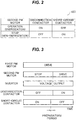
- FIG. 2 is a table illustrating operation modes in which the disconnection contactors 108 and short-circuit contactors 109 are controlled in accordance with commands from the host controller 122.
- the calculator 110 upon receiving a command to cause the second PM motor 120B to operate, i.e., a command to energize the second PM motor 120B, from the host controller 122, the calculator 110 turns the disconnection contactors 108 on, and turns the short-circuit contactors 109 off.
- the calculator 110 upon receiving a command to stop the second PM motor 120B, i.e., a command to supply no current to the second PM motor 120B, from the host controller 122, the calculator 110 turns the disconnection contactors 108 off, and turns the short-circuit contactors 109 on.
- “on” indicates that they are in conduction states
- "off” indicates that they are in open states.
- FIG. 3 is a schematic diagram illustrating a first example of an operating sequence of the first PM motor 120A, second PM motor 120B, inverter 105, disconnection contactors 108, and short-circuit contactors 109.
- FIG. 3 illustrates a sequence in the case of driving the second PM motor 120B that has been stopped, in addition to the first PM motor 120A that is being driven.
- the disconnection contactors 108 are turned off, and the power supply from the inverter 105 to the second PM motor 120B is disconnected. Meanwhile, the short-circuit contactors 109 are turned on, and the second PM motor 120B is in a short-circuit state.
- the short-circuit contactors 109 are turned off and the second PM motor 120B is switched from the short-circuit state to an open state, and then the disconnection contactors 108 are turned on, resulting in a state where power is supplied from the inverter 105 to the second PM motor 120B, and the current paths between the inverter 105 and the second PM motor 120B are connected. Thereby, power is supplied from the inverter 105 to the second PM motor 120B, and the second PM motor 120B is also driven.
- the disconnection contactors 108 and short-circuit contactors 109 are, for example, relays or semiconductor switching elements. Whichever is used, it takes time to turn on or off. A preparatory period is provided after the short-circuit contactors 109 are turned off and before the disconnection contactors 108 are turned on. This is because it takes time for the disconnection contactors 108 to switch between the on and off states, and is to prevent a situation in which the short-circuit contactors 109 turn off simultaneously with the disconnection contactors 108 turning on, or a situation in which the short-circuit contactors 109 are turned off after the disconnection contactors 108 are turned on.
- the short-circuit contactors 109 were turned off after turning on of the disconnection contactors 108, a state in which the disconnection contactors 108 and short-circuit contactors 109 are both turned on would occur, the outputs of the inverter 105 would be short-circuited, and upon operation of the inverter 105, the inverter 105 would be stopped or damaged due to overcurrent.
- a rotational frequency command value provided from the inverter 105 to the first PM motor 120A is decreased. While the amount of current flowing through the first PM motor 120A is small, the short-circuit contactors 109 are turned off and the disconnection contactors 108 are turned on, so that the current paths between the inverter 105 and the second PM motor 120B are connected. Then, the rotational frequency command value provided from the inverter 105 to the first PM motor 120A and second PM motor 120B is increased again.
- the disconnection contactors 108 are turned on while the amount of current flowing through the first PM motor 120A is small, the second PM motor 120B easily follows the first PM motor 120A, and the step-out can be prevented.
- the short-circuit contactors 109 are turned on. However, since the disconnection contactors 108 are turned off and the power supply from the inverter 105 to the second PM motor 120B is disconnected, the short-circuit contactors 109 may be turned off.
- the rotational frequency of the first PM motor 120A is decreased, the frequency of the AC voltage output by the inverter 105 is also decreased, and the difference between the rotational frequency of the second PM motor 120B in the stopped state and the frequency of the AC voltage output by the inverter 105 is decreased. This facilitates synchronous pull-in of the rotor of the second PM motor 120B, and can prevent step-out of the second PM motor 120B.
- the output of voltage from the inverter 105 is stopped, and the driving of the first PM motor 120A is stopped.
- the short-circuit contactors 109 are turned off and the second PM motor 120B is switched from the short-circuit state to the open state, and then the disconnection contactors 108 are turned on and the current paths between the inverter 105 and the second PM motor 120B are connected.
- the voltage from the inverter 105 is output, and the first PM motor 120A and second PM motor 120 connected to the inverter 105 are driven.
- the current paths between the inverter 105 and the second PM motor 120B are connected while the first PM motor 120A and second PM motor 120B are stopped. This prevents a large voltage from being suddenly applied to the second PM motor 120B after the second PM motor 120B is driven, and can prevent step-out of the second PM motor 120B.
- the following describes an operation of stopping the second PM motor 120B that is being driven.
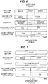
- FIG. 6 is a schematic diagram illustrating a third example of an operating sequence of the first PM motor 120A, second PM motor 120B, inverter 105, disconnection contactors 108, and short-circuit contactors 109.
- FIG. 6 illustrates a sequence in the case of stopping the second PM motor 120B that is being driven.
- the disconnection contactors 108 are turned on, and when it is stopped, the short-circuit contactors 109 are turned on to prevent free running.
- the disconnection contactors 108 and short-circuit contactors 109 are, for example, relays or semiconductor switching elements. Whichever contactor is used, it takes time to turn on or off.
- the short-circuit contactors 109 are inserted to short-circuit the phases.
- the voltage output of the inverter 105 is stopped once, and then the state of the short-circuit contactors 109 is switched.
- a switching period during which the inverter 105 is stopped is provided.
- a preparatory period is provided after the disconnection contactors 108 are turned off and before the short-circuit contactors 109 are turned on.
- FIG. 7 is a schematic diagram illustrating a fourth example of an operating sequence of the first PM motor 120A, second PM motor 120B, inverter 105, disconnection contactors 108, and short-circuit contactors 109.
- the disconnection contactors 108 are inserted in series with respect to the inverter 105 and second PM motor 120B. Thus, when the disconnection contactors 108 are turned off, no voltage is applied from the inverter 105 to the second PM motor 120B. Thus, by turning the disconnection contactors 108 off while the voltage is being output by the inverter 105, and turning the short-circuit contactors 109 on after the disconnection contactors 108 are turned off, it is possible to stop the second PM motor 120B without stopping the inverter 105 and first PM motor 120A.
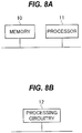
- Part or the whole of the calculator 110 and host controller 122 described above can be formed by, for example, a memory 10 and a processor 11, such as a central processing unit (CPU), that executes a program stored in the memory 10, as illustrated in FIG. 8A .
- a program may be provided via a network, or may be recorded and provided in a recording medium.
- Such a program may be provided as a program product, for example.
- part or the whole of the calculator 110 and host controller 122 may be implemented by a single processor 11, or may be implemented by different processors 11.
- part of the calculator 110 and host controller 122 may be formed by processing circuitry 12, such as a single circuit, a composite circuit, a programmed processor, a parallel-programmed processor, application specific integrated circuits (ASICs), or a field programmable gate array (FPGA), as illustrated in FIG. 8B , for example.
- processing circuitry 12 such as a single circuit, a composite circuit, a programmed processor, a parallel-programmed processor, application specific integrated circuits (ASICs), or a field programmable gate array (FPGA), as illustrated in FIG. 8B , for example.
- FIG. 9 is a schematic diagram illustrating a configuration of a motor driving device 200 according to a second embodiment and its peripheral circuitry.
- the motor driving device 200 includes at least a converter 101, an inverter 105, disconnection contactors 108, short-circuit contactors 109, and a calculator 210.
- the motor driving device 100 also includes a bus voltage sensor 104, first current sensors 106, second current sensors 107, and an overcurrent detector 213.
- the motor driving device 200 drives a first PM motor 120A and a second PM motor 120B.
- the converter 101, inverter 105, disconnection contactors 108, short-circuit contactors 109, bus voltage sensor 104, first current sensors 106, and second current sensors 107 of the second embodiment are the same as those of the first embodiment.
- At least one of the second current sensors 107A and 107B is used as a brake current sensor that detects a current flowing through the second PM motor 120B when the short-circuit contactors 109 are turned on.
- the second current sensor 107A is used as the brake current sensor, and the second current sensor 107A will also be referred to as the brake current sensor 214.
- the current value detected by the brake current sensor 214 when the short-circuit contactors 109 are turned on will be referred to as the brake current value.
- the brake current value detected by the brake current sensor 214 is provided to the overcurrent detector 213.
- the overcurrent detector 213 determines, on the basis of the brake current value, whether a brake current that is the current flowing through the second PM motor 120B is an overcurrent. For example, when the brake current value is greater than an overcurrent determination value that is a predetermined threshold, the overcurrent detector 213 detects that the brake current is an overcurrent. On the other hand, when the brake current value is not greater than the overcurrent determination value, the overcurrent detector 213 detects that the brake current is not an overcurrent.
- the overcurrent detector 213 provides the calculator 210 with an overcurrent detection signal indicating whether the brake current is an overcurrent, thereby informing the calculator 210 of whether the brake current is an overcurrent.
- the calculator 210 is a controller that controls processes in the motor driving device 200.
- the calculator 210 performs the same processing as the calculator 110 of the first embodiment. In addition, after the short-circuit contactors 109 are turned on, when the calculator 210 receives, from the overcurrent detector 213, an overcurrent detection signal indicating that the brake current is an overcurrent, the calculator 210 switches the short-circuit contactors 109 from connection to disconnection.
- FIG. 10 is a schematic diagram illustrating a relationship between the brake current and the overcurrent detection signal.
- FIG. 10 is merely a schematic diagram illustrating an operation example, and illustrates waveforms and the like in a simple manner.
- FIG. 10 illustrates an operation in a case where, when the disconnection contactors 108 are turned off and the short-circuit contactors 109 are turned on, the brake current value, which is the current value of the current flowing through the second PM motor 120B, gradually increases.
- the state where the disconnection contactors 108 are turned off and the short-circuit contactors 109 are turned on is a state where no power is supplied from the inverter 105 to the second PM motor 120B and brake current is allowed to flow to prevent free-running rotation of the second PM motor 120B.
- FIG. 10 it is a state where the rotational frequency R of the second PM motor 120B is not zero and thus brake current is flowing through the second PM motor 120B.
- an overcurrent determination signal S changes from a state where it indicates No to a state where it indicates Yes.
- the overcurrent determination signal S is in the state where it indicates No, it indicates that the brake current is not an overcurrent, and when the overcurrent determination signal S is in the state where it indicates Yes, it indicates that the brake current is an overcurrent.
- the short-circuit contactors 109 are turned off. This brings the second PM motor 120B out of the short-circuit state, and places the terminals of the second PM motor 120B in open states, so that the brake current value Bi becomes zero.
- the disconnection contactors 108 are left turned off.
- the overcurrent detector 213 performs the overcurrent determination on the basis of the value detected by the brake current sensor 214.
- the brake current sensor 214 is disposed between the short-circuit contactors 109 and the second PM motor 120B.
- Part or the whole of the overcurrent detector 213 can be formed by the memory 10 and processor 11 as illustrated in FIG. 8A , for example.
- the overcurrent detector 213 may be implemented by a processor 11 that implements the calculator 210, or may be implemented by another processor 11.
- part of the overcurrent detector 213 can be formed by a processing circuitry 12 as illustrated in FIG. 8B , for example.
- the overcurrent detector 213 is provided. However, instead of providing the overcurrent detector 213, the calculator 210 may perform the overcurrent determination performed by the overcurrent detector 213.
- FIG. 11 is a block diagram schematically illustrating a configuration of an air conditioner 300 according to a third embodiment.
- the air conditioner 300 includes an outdoor unit 330 and an indoor unit 340.
- the outdoor unit 330 is installed outdoors, the indoor unit 340 is installed indoors, and they condition indoor air.
- the outdoor unit 330 includes a motor driving device 100 or 200, a first PM motor 120A, a second PM motor 120B, an AC power supply 121, a host controller 122, a first fan 331A, a second fan 331B, a first heat exchanger 332A, and a second heat exchanger 332B.
- the motor driving device 100 or 200 of the third embodiment is the same as that of the first or second embodiment.
- the first PM motor 120A and second PM motor 120B of the third embodiment are the same as those of the first embodiment.
- the first PM motor 120A is connected to the first fan 331A and used to rotate the first fan 331A.
- the second PM motor 120B is connected to the second fan 331B and used to rotate the second fan 331B.
- the AC power supply 121 and host controller 122 of the third embodiment are the same as those of the first embodiment.
- the first fan 331A is used to vent air heated or cooled by the first heat exchanger 332A.
- the second fan 331B is used to vent air heated or cooled by the second heat exchanger 332B.
- the first heat exchanger 332A exchanges heat of refrigerant.
- the second heat exchanger 332B exchanges heat of refrigerant.
- the path through which refrigerant flows in a refrigeration cycle may be switched depending on the required air conditioning capacity.
- the required air conditioning capacity is low, heat exchange is performed while refrigerant is flowed through only the first heat exchanger 332A.
- the second PM motor 120B need not be driven.
- the disconnection contactors 108 are turned off, and power is supplied from the inverter 105 to only the first PM motor 120A.
- the second PM motor 120B since the terminals of the second PM motor 120B are in open states, when outside wind blows, the second PM motor 120B enters a free-running state.
- the free-running rotation is reduced by turning the short-circuit contactors 109 on, as described in the first or second embodiment.
- both the first PM motor 120A and second PM motor 120B need to be driven.
- the disconnection contactors 108 are turned on, and the short-circuit contactors 109 are turned off, thereby allowing the two fans 331A and 331B to be rotated.
- the driving of the multiple PM motors 120A and 120B can be switched depending on the operating condition of the air conditioner 300, by the motor driving device 100 or 200 described in the first or second embodiment.
- the outdoor unit 330 illustrated in FIG. 11 is of a top-flow type, the outdoor unit 330 may be of a side-flow type.
- At least two disconnection contactors may be inserted in series in at least two power lines of the first U-phase power line 111u, first V-phase power line 111v, and first W-phase power line 111w between the first PM motor 120A and the positions where the second U-phase power line 112u, second V-phase power line 112v, and second W-phase power line 112w are branched.
- At least two short-circuit contactors may be inserted between the first PM motor 120A and the disconnection contactors inserted in the at least two power lines of the first U-phase power line 111u, first V-phase power line 111v, and first W-phase power line 111w so that they connect or disconnect between the second U-phase power line 112u, second V-phase power line 112v, and second W-phase power line 112w.
- a brake current sensor is provided also in the first U-phase power line 111u, first V-phase power line 111v, or first W-phase power line 111w.
- the current values of the respective phases of the first PM motor 120A and second PM motor 120B are detected by the first current sensors 106 and second current sensors 107.
- the first to third embodiments are not limited to such an example.
- shunt resistor(s) (not illustrated) are disposed at position(s), such as point P1 or points P2-P4 in FIG. 1 , and the calculator 110 or 210 calculates the current values from the terminal voltage(s).
- one of the set of the first current sensors 106 and the set of the second current sensors 107 may be removed.
- at least one brake current sensor 214 is required.
- the disconnection contactors 108 and short-circuit contactors 109 are provided. Thereby, it is possible to prevent free running of the second PM motor 120B.
- the short-circuit contactors 109 are provided between the disconnection contactors 108 and the second PM motor 120B. Thereby, it is possible to prevent overcurrent from flowing through the inverter 105 when the short-circuit contactors 109 are turned on.
- the calculator 210 switches the short-circuit contactors 109 from connection to disconnection. Thereby, it is possible to prevent problems, such as demagnetization in the second PM motor 120B.
- the brake current sensor 214 is provided between the short-circuit contactors 109 and the second PM motor 120B, and thus can accurately detect a current flowing through the second PM motor 120B.
- the first PM motor 120A is used to rotate the first fan 331A
- the second PM motor 120B is used to rotate the second fan 331B.
Landscapes
- Engineering & Computer Science (AREA)
- Power Engineering (AREA)
- Chemical & Material Sciences (AREA)
- Combustion & Propulsion (AREA)
- Mechanical Engineering (AREA)
- General Engineering & Computer Science (AREA)
- Physics & Mathematics (AREA)
- Fluid Mechanics (AREA)
- Control Of Multiple Motors (AREA)
- Control Of Ac Motors In General (AREA)
- Motor Or Generator Cooling System (AREA)
Abstract
Description
- The present invention relates to a motor driving device and an air conditioner.
- In controlling a motor, an inverter is used. There is a known technique of controlling multiple motors with a single inverter. For example,
Patent Literature 1 describes an electric device that drives a first motor having multiple phases and a second motor having the same number of phases as the first motor with a single inverter circuit on the basis of single-mode PWM control in a state where the phases of the first motor and the phases of the second motor are connected to common output lines for the respective phases. - Patent Literature 1: Japanese Patent No.
4305021 - In air conditioners in which multiple outdoor fan motors are installed, it is common to change the number of driven fan motors depending on the air conditioning load. This is to change the number of driven outdoor fan motors depending on the air conditioning load, and for example, when the air conditioning load is low, only one of the outdoor fan motors is driven, and when the air conditioning load is high, the number of driven outdoor fan motors is increased.
- Thus, in a case where the number of driven outdoor fan motors is increased, when an outdoor fan motor that is rotated by a disturbance factor and is in a free-running state is driven, counter electromotive voltage occurs, and excessive inrush current may flow through the fan motor. Further, when permanent magnet synchronous motors (referred to below as PM motors) are used as the fan motors, the excessive inrush current may demagnetize the rotor magnets.
- One or more aspects of the present invention are intended to make it possible, in a motor driving device that drives multiple fan motors with a single inverter, when a fan motor in a free-running state is driven in addition to already driven fan motor(s), to prevent excessive current from flowing through the fan motor and prevent demagnetization of a permanent magnet of the PM motor.
- A motor driving device according to an aspect of the present invention is a motor driving device for driving a first permanent magnet synchronous motor and a second permanent magnet synchronous motor, and includes a converter to generate a direct-current voltage; an inverter to generate a three-phase alternating-current voltage from the direct-current voltage; three first power lines to supply the three-phase alternating-current voltage to the first permanent magnet synchronous motor; three second power lines to supply the three-phase alternating-current voltage to the second permanent magnet synchronous motor; at least two disconnection contactors, each of the disconnection contactors switching between connection and disconnection of each of at least two of the three second power lines; at least two short-circuit contactors, each of the short-circuit contactors switching between connection and disconnection between the two second power lines of each of at least two of pairs of the three second power lines; and a controller to control the at least two disconnection contactors and the at least two short-circuit contactors.
- An air conditioner according to an aspect of the present invention is an air conditioner including a first permanent magnet synchronous motor; a second permanent magnet synchronous motor; and a motor driving device to drive the first permanent magnet synchronous motor and the second permanent magnet synchronous motor, wherein the motor driving device includes: a converter to generate a direct-current voltage; an inverter to generate a three-phase alternating-current voltage from the direct-current voltage; three first power lines to supply the three-phase alternating-current voltage to the first permanent magnet synchronous motor; three second power lines to supply the three-phase alternating-current voltage to the second permanent magnet synchronous motor; at least two disconnection contactors, each of the disconnection contactors switching between connection and disconnection of each of at least two of the three second power lines; at least two short-circuit contactors, each of the short-circuit contactors switching between connection and disconnection between the two second power lines of each of at least two of pairs of the three second power lines; and a controller to control the at least two disconnection contactors and the at least two short-circuit contactors.
- According to an aspect of the present invention, in a motor driving device that drives a first permanent magnet synchronous motor and a second permanent magnet synchronous motor with a single inverter, by providing disconnection contactors to disconnect between the second permanent magnet synchronous motor and the inverter and short-circuit contactors to short-circuit the second permanent magnet synchronous motor, and connecting the second permanent magnet synchronous motor to the inverter and driving the second permanent magnet synchronous motor after short-circuiting the second permanent magnet synchronous motor, it is possible to prevent occurrence of counter electromotive voltage from the second permanent magnet synchronous motor and demagnetization of a permanent magnet of the second permanent magnet synchronous motor.
-
-
FIG. 1 is a schematic diagram illustrating a configuration of a motor driving device according to a first embodiment and its peripheral circuitry. -
FIG. 2 is a table illustrating operational modes in which disconnection contactors and short-circuit contactors are controlled. -
FIG. 3 is a schematic diagram illustrating a first example of an operating sequence of a first PM motor, a second PM motor, an inverter, the disconnection contactors, and the short-circuit contactors. -
FIG. 4 is a schematic diagram illustrating a rotational frequency command value provided from the inverter to the first PM motor. -
FIG. 5 is a schematic diagram illustrating a second example of an operating sequence of the first PM motor, second PM motor, inverter, disconnection contactors, and short-circuit contactors. -
FIG. 6 is a schematic diagram illustrating a third example of an operating sequence of the first PM motor, second PM motor, inverter, disconnection contactors, and short-circuit contactors. -
FIG. 7 is a schematic diagram illustrating a fourth example of an operating sequence of the first PM motor, second PM motor, inverter, disconnection contactors, and short-circuit contactors. -
FIGs. 8A and 8B are schematic diagrams illustrating hardware configuration examples. -
FIG. 9 is a schematic diagram illustrating a configuration of a motor driving device according to a second embodiment and its peripheral circuitry. -
FIG. 10 is a schematic diagram illustrating a relationship between a brake current and an overcurrent detection signal. -
FIG. 11 is a block diagram schematically illustrating a configuration of an air conditioner according to a third embodiment. -
FIG. 1 is a schematic diagram illustrating a configuration of amotor driving device 100 according to a first embodiment and its peripheral circuitry. - The
motor driving device 100 is connected to an alternating-current (AC)power supply 121, afirst PM motor 120A, and asecond PM motor 120B, and includes at least aconverter 101, aninverter 105,disconnection contactors circuit contactors calculator 110. - The
motor driving device 100 also includes abus voltage sensor 104, firstcurrent sensors current sensors - With the above configuration, the
motor driving device 100 drives thefirst PM motor 120A andsecond PM motor 120B. - The
converter 101 generates a direct-current (DC) voltage. For example, theconverter 101 converts an AC voltage from theAC power supply 121 to a DC voltage by rectifying the AC voltage with arectifier 102 and then smoothing it with asmoothing unit 103, such as a capacitor. The DC voltage resulting from the conversion by theconverter 101 is output to theinverter 105. - The
bus voltage sensor 104 detects a DC bus voltage applied to theinverter 105. A bus voltage value that is a voltage value of the detected DC bus voltage is supplied to thecalculator 110. - The
inverter 105 generates a three-phase AC voltage from the DC voltage supplied from theconverter 101, and outputs the three-phase AC voltage to thefirst PM motor 120A andsecond PM motor 120B. Thefirst PM motor 120A andsecond PM motor 120B are connected in parallel to the output of theinverter 105. For example, thefirst PM motor 120A is connected to theinverter 105 through a firstU-phase power line 111u, a first V-phase power line 111v, and a first W-phase power line 111w, and thesecond PM motor 120B is connected to theinverter 105 through a secondU-phase power line 112u branched from the firstU-phase power line 111u, a second V-phase power line 112v branched from the first V-phase power line 111v, and a second W-phase power line 112w branched from the first W-phase power line 111w. - Here, each of the first
U-phase power line 111u, first V-phase power line 111v, and first W-phase power line 111w is a first power line for supplying the three-phase AC voltage to thefirst PM motor 120A. - Also, each of the second
U-phase power line 112u, second V-phase power line 112v, and second W-phase power line 112w is a second power line for supplying the three-phase AC voltage to thesecond PM motor 120B. - The first
current sensors first PM motor 120A. First current values that are the detected current values are supplied to thecalculator 110. For example, the firstcurrent sensors - Here, the first
current sensor 106A detects the current flowing through the firstU-phase power line 111u, and the firstcurrent sensor 106B detects the current flowing through the first W-phase power line 111w. However, the first embodiment is not limited to such an example. In the first embodiment, it is sufficient that the currents flowing through at least two first power lines of the firstU-phase power line 111u, first V-phase power line 111v, and first W-phase power line 111w be detected, and all the currents flowing through the first power lines may be detected. - When the first
current sensors - The second
current sensors second PM motor 120B. Second current values that are the detected current values are supplied to thecalculator 110. For example, the secondcurrent sensors - Here, the second
current sensor 107A detects the current flowing through the secondU-phase power line 112u, and the secondcurrent sensor 107B detects the current flowing through the second W-phase power line 112w. However, the first embodiment is not limited to such an example. In the first embodiment, it is sufficient that the currents flowing through at least two second power lines of the secondU-phase power line 112u, second V-phase power line 112v, and second W-phase power line 112w be detected, and all the currents flowing through the second power lines may be detected. - When the second
current sensors - The
disconnection contactors circuit contactors inverter 105 and thesecond PM motor 120B. - The
disconnection contactors inverter 105 and thesecond PM motor 120B. Each of thedisconnection contactors second PM motor 120B is controlled by operation of thedisconnection contactors - For example, when the
disconnection contactors inverter 105 is connected to thesecond PM motor 120B, and power from theinverter 105 is supplied to thesecond PM motor 120B. On the other hand, when thedisconnection contactors inverter 105 is disconnected from thesecond PM motor 120B, and no power is supplied from theinverter 105 to thesecond PM motor 120B. - The
disconnection contactors calculator 110. Thus, when thedisconnection contactors - Here, the
disconnection contactor 108A is inserted in the secondU-phase power line 112u, and thedisconnection contactor 108B is inserted in the second W-phase power line 112w. However, the first embodiment is not limited to such an example. It is sufficient that disconnection contactors 108 be inserted in at least two second power lines of the secondU-phase power line 112u, second V-phase power line 112v, and second W-phase power line 112w, and it is possible that disconnection contactors 108 are inserted in all thepower lines - The short-
circuit contactors second PM motor 120B. Each of the short-circuit contactors 190A and 190B is inserted between the two second power lines included in one of the pairs of the secondU-phase power line 112u, second V-phase power line 112v, and second W-phase power line 112w. Each of the short-circuit contactors second PM motor 120B can be controlled by operation of the short-circuit contactors - For example, when the short-
circuit contactors U-phase power line 112u and second V-phase power line 112v are connected to each other, and the second V-phase power line 112v and second W-phase power line 112w are connected to each other, so that the paths of the currents flowing through thesecond PM motor 120B are closed in thesecond PM motor 120B. Thereby, no power is supplied from theinverter 105 to thesecond PM motor 120B, power supplied to thesecond PM motor 120B is consumed by thesecond PM motor 120B itself, and thesecond PM motor 120B can be braked. Thus, even when thesecond PM motor 120B is in a free-running state, thesecond PM motor 120B is braked and stops rotating, so that the counter electromotive voltage can be reduced. - On the other hand, when the short-
circuit contactors U-phase power line 112u and second V-phase power line 112v are disconnected from each other, the second V-phase power line 112v and second W-phase power line 112w are disconnected from each other, the current paths are formed between theinverter 105 and thesecond PM motor 120B, and power is supplied from theinverter 105 to thesecond PM motor 120B. - The short-
circuit contactors calculator 110. Thus, when the short-circuit contactors - Here, the short-
circuit contactor 109A is inserted between the secondU-phase power line 112u and the second V-phase power line 112v, and the short-circuit contactor 109B is inserted between the second V-phase power line 112v and the second W-phase power line 112w. However, the first embodiment is not limited to such an example. It is sufficient that a short-circuit contactor 109 be inserted between each of at least two of the pair of the secondU-phase power line 112u and second V-phase power line 112v, the pair of the second V-phase power line 112v and second W-phase power line 112w, and the pair of the secondU-phase power line 112u and second W-phase power line 112w, and it is possible that a short-circuit contactor 109 is inserted between each of all the pairs. - The
calculator 110 is a controller that controls processes in themotor driving device 100. - For example, the
calculator 110 performs motor control calculation and generates driving signals for respective switching elements of theinverter 105, on the basis of the detection results of the first current sensors 106, second current sensors 107, andbus voltage sensor 104. Here, thecalculator 110 performs vector control. Specifically, thecalculator 110 determines, from the detection results of the first current sensors 106, a current value flowing through each phase of thefirst PM motor 120A, and performs coordinate conversion from stationary three-phase coordinates to rotational two-phase coordinates, on the determined current values, thereby calculating first current values in dq-axes. Similarly, thecalculator 110 determines, from the detection results of the second current sensors 107, a current value flowing through each phase of thesecond PM motor 120B, and performs coordinate conversion from stationary three-phase coordinates to rotational two-phase coordinates, on the determined current values, thereby calculating second current values in dq-axes. Thecalculator 110 generates the driving signals for theinverter 105 so that the first current values calculated as above are equal to ideal values, in consideration of the difference between the first current values and the second current values. - The above-described vector control is merely an example, and the
calculator 110 may use any control method. - Also, the
calculator 110 controls the disconnection contactors 108 and short-circuit contactors 109 in accordance with commands from ahost controller 122. - For example, when stopping the
second PM motor 120B, thecalculator 110 switches the disconnection contactors 108 from connection to disconnection and switches the short-circuit contactors 109 from disconnection to connection. -
FIG. 2 is a table illustrating operation modes in which the disconnection contactors 108 and short-circuit contactors 109 are controlled in accordance with commands from thehost controller 122. - As illustrated in
FIG. 2 , upon receiving a command to cause thesecond PM motor 120B to operate, i.e., a command to energize thesecond PM motor 120B, from thehost controller 122, thecalculator 110 turns the disconnection contactors 108 on, and turns the short-circuit contactors 109 off. On the other hand, upon receiving a command to stop thesecond PM motor 120B, i.e., a command to supply no current to thesecond PM motor 120B, from thehost controller 122, thecalculator 110 turns the disconnection contactors 108 off, and turns the short-circuit contactors 109 on. Here, "on" indicates that they are in conduction states, and "off" indicates that they are in open states. - The operation will now be described.
FIG. 3 is a schematic diagram illustrating a first example of an operating sequence of thefirst PM motor 120A,second PM motor 120B,inverter 105, disconnection contactors 108, and short-circuit contactors 109.FIG. 3 illustrates a sequence in the case of driving thesecond PM motor 120B that has been stopped, in addition to thefirst PM motor 120A that is being driven. - As illustrated in
FIG. 3 , when thefirst PM motor 120A is being driven and thesecond PM motor 120B is stopped, the disconnection contactors 108 are turned off, and the power supply from theinverter 105 to thesecond PM motor 120B is disconnected. Meanwhile, the short-circuit contactors 109 are turned on, and thesecond PM motor 120B is in a short-circuit state. - Then, the short-circuit contactors 109 are turned off and the
second PM motor 120B is switched from the short-circuit state to an open state, and then the disconnection contactors 108 are turned on, resulting in a state where power is supplied from theinverter 105 to thesecond PM motor 120B, and the current paths between theinverter 105 and thesecond PM motor 120B are connected. Thereby, power is supplied from theinverter 105 to thesecond PM motor 120B, and thesecond PM motor 120B is also driven. - Here, it is assumed that the disconnection contactors 108 and short-circuit contactors 109 are, for example, relays or semiconductor switching elements. Whichever is used, it takes time to turn on or off. A preparatory period is provided after the short-circuit contactors 109 are turned off and before the disconnection contactors 108 are turned on. This is because it takes time for the disconnection contactors 108 to switch between the on and off states, and is to prevent a situation in which the short-circuit contactors 109 turn off simultaneously with the disconnection contactors 108 turning on, or a situation in which the short-circuit contactors 109 are turned off after the disconnection contactors 108 are turned on.
- If the short-circuit contactors 109 were turned off after turning on of the disconnection contactors 108, a state in which the disconnection contactors 108 and short-circuit contactors 109 are both turned on would occur, the outputs of the
inverter 105 would be short-circuited, and upon operation of theinverter 105, theinverter 105 would be stopped or damaged due to overcurrent. - However, in the case of the switching sequence of
FIG. 3 , since the AC voltage is suddenly applied to thesecond PM motor 120B in a stopped state, inrush current flows at the time of the switching, which may demagnetize a magnet of a rotor of thesecond PM motor 120B. Due to the nature of the PM motor, when the rotational frequency of the rotor of thesecond PM motor 120B is greatly different from the frequency of the AC voltage output by theinverter 105, the output voltage of theinverter 105 fails to be synchronized with the rotor of thesecond PM motor 120B, which may lead to step-out. - Thus, as illustrated in
FIG. 4 , before the short-circuit contactors 109 are turned off and the disconnection contactors 108 are turned on, a rotational frequency command value provided from theinverter 105 to thefirst PM motor 120A is decreased. While the amount of current flowing through thefirst PM motor 120A is small, the short-circuit contactors 109 are turned off and the disconnection contactors 108 are turned on, so that the current paths between theinverter 105 and thesecond PM motor 120B are connected. Then, the rotational frequency command value provided from theinverter 105 to thefirst PM motor 120A andsecond PM motor 120B is increased again. - Since the disconnection contactors 108 are turned on while the amount of current flowing through the
first PM motor 120A is small, thesecond PM motor 120B easily follows thefirst PM motor 120A, and the step-out can be prevented. - In the operating sequence illustrated in
FIG. 3 , while thefirst PM motor 120A is being driven and thesecond PM motor 120B is stopped, the short-circuit contactors 109 are turned on. However, since the disconnection contactors 108 are turned off and the power supply from theinverter 105 to thesecond PM motor 120B is disconnected, the short-circuit contactors 109 may be turned off. - Also, the rotational frequency of the
first PM motor 120A is decreased, the frequency of the AC voltage output by theinverter 105 is also decreased, and the difference between the rotational frequency of thesecond PM motor 120B in the stopped state and the frequency of the AC voltage output by theinverter 105 is decreased. This facilitates synchronous pull-in of the rotor of thesecond PM motor 120B, and can prevent step-out of thesecond PM motor 120B. - The following describes, with reference to
FIG. 5 , an operation of preventing step-out of thesecond PM motor 120B in a simpler way without performing control of the rotational frequency command value. InFIG. 5 , the operation when only thefirst PM motor 120A is being driven and thesecond PM motor 120B is stopped is the same as that inFIG. 3 , and the subsequent operation differs from the operating sequence illustrated inFIG. 3 . - As illustrated in
FIG. 5 , when thefirst PM motor 120A is being driven and thesecond PM motor 120B is stopped, a voltage is output from theinverter 105, the disconnection contactors 108 are turned off, and the short-circuit contactors 109 are turned on. - Then, the output of voltage from the
inverter 105 is stopped, and the driving of thefirst PM motor 120A is stopped. In a switching period during which thefirst PM motor 120A andsecond PM motor 120B are stopped, the short-circuit contactors 109 are turned off and thesecond PM motor 120B is switched from the short-circuit state to the open state, and then the disconnection contactors 108 are turned on and the current paths between theinverter 105 and thesecond PM motor 120B are connected. Then, the voltage from theinverter 105 is output, and thefirst PM motor 120A andsecond PM motor 120 connected to theinverter 105 are driven. - As described above, the current paths between the
inverter 105 and thesecond PM motor 120B are connected while thefirst PM motor 120A andsecond PM motor 120B are stopped. This prevents a large voltage from being suddenly applied to thesecond PM motor 120B after thesecond PM motor 120B is driven, and can prevent step-out of thesecond PM motor 120B. - The following describes an operation of stopping the
second PM motor 120B that is being driven. -
FIG. 6 is a schematic diagram illustrating a third example of an operating sequence of thefirst PM motor 120A,second PM motor 120B,inverter 105, disconnection contactors 108, and short-circuit contactors 109. -
FIG. 6 illustrates a sequence in the case of stopping thesecond PM motor 120B that is being driven. - As illustrated in
FIG. 2 , when thesecond PM motor 120B is driven, the disconnection contactors 108 are turned on, and when it is stopped, the short-circuit contactors 109 are turned on to prevent free running. - Here, it is assumed that the disconnection contactors 108 and short-circuit contactors 109 are, for example, relays or semiconductor switching elements. Whichever contactor is used, it takes time to turn on or off. The short-circuit contactors 109 are inserted to short-circuit the phases. Thus, as illustrated in
FIG. 6 , the voltage output of theinverter 105 is stopped once, and then the state of the short-circuit contactors 109 is switched. Thus, as illustrated inFIG. 6 , a switching period during which theinverter 105 is stopped is provided. - Since it also takes time for the state of the disconnection contactors 108 to switch, a preparatory period is provided after the disconnection contactors 108 are turned off and before the short-circuit contactors 109 are turned on.
-
FIG. 7 is a schematic diagram illustrating a fourth example of an operating sequence of thefirst PM motor 120A,second PM motor 120B,inverter 105, disconnection contactors 108, and short-circuit contactors 109. - As described above, the disconnection contactors 108 are inserted in series with respect to the
inverter 105 andsecond PM motor 120B. Thus, when the disconnection contactors 108 are turned off, no voltage is applied from theinverter 105 to thesecond PM motor 120B. Thus, by turning the disconnection contactors 108 off while the voltage is being output by theinverter 105, and turning the short-circuit contactors 109 on after the disconnection contactors 108 are turned off, it is possible to stop thesecond PM motor 120B without stopping theinverter 105 andfirst PM motor 120A. - In this case, it is not necessary to provide the switching period as illustrated in
FIG. 6 . However, since it takes time for the state of the disconnection contactors 108 to switch, a preparatory period is provided after the disconnection contactors 108 are turned off and before the short-circuit contactors 109 are turned on. - Part or the whole of the
calculator 110 andhost controller 122 described above can be formed by, for example, amemory 10 and aprocessor 11, such as a central processing unit (CPU), that executes a program stored in thememory 10, as illustrated inFIG. 8A . Such a program may be provided via a network, or may be recorded and provided in a recording medium. Such a program may be provided as a program product, for example. - In this case, part or the whole of the
calculator 110 andhost controller 122 may be implemented by asingle processor 11, or may be implemented bydifferent processors 11. - Also, part of the
calculator 110 andhost controller 122 may be formed by processingcircuitry 12, such as a single circuit, a composite circuit, a programmed processor, a parallel-programmed processor, application specific integrated circuits (ASICs), or a field programmable gate array (FPGA), as illustrated inFIG. 8B , for example. - In the case of the
motor driving device 100 according to the first embodiment, it is conceivable that when the disconnection contactors 108 are turned off and the short-circuit contactors 109 are turned on, an increase in the rotational frequency of thesecond PM motor 120B due to free running increases the motor current, thereby causing problems, such as demagnetization. Thus, the second embodiment addresses such problems. -
FIG. 9 is a schematic diagram illustrating a configuration of amotor driving device 200 according to a second embodiment and its peripheral circuitry. - The
motor driving device 200 includes at least aconverter 101, aninverter 105, disconnection contactors 108, short-circuit contactors 109, and acalculator 210. - The
motor driving device 100 also includes abus voltage sensor 104, first current sensors 106, second current sensors 107, and anovercurrent detector 213. - With the above configuration, the
motor driving device 200 drives afirst PM motor 120A and asecond PM motor 120B. - The
converter 101,inverter 105, disconnection contactors 108, short-circuit contactors 109,bus voltage sensor 104, first current sensors 106, and second current sensors 107 of the second embodiment are the same as those of the first embodiment. - However, at least one of the second
current sensors second PM motor 120B when the short-circuit contactors 109 are turned on. Here, it is assumed that the secondcurrent sensor 107A is used as the brake current sensor, and the secondcurrent sensor 107A will also be referred to as the brakecurrent sensor 214. Also, the current value detected by the brakecurrent sensor 214 when the short-circuit contactors 109 are turned on will be referred to as the brake current value. - The brake current value detected by the brake
current sensor 214 is provided to theovercurrent detector 213. - When the short-circuit contactors 109 are turned on, the
overcurrent detector 213 determines, on the basis of the brake current value, whether a brake current that is the current flowing through thesecond PM motor 120B is an overcurrent. For example, when the brake current value is greater than an overcurrent determination value that is a predetermined threshold, theovercurrent detector 213 detects that the brake current is an overcurrent. On the other hand, when the brake current value is not greater than the overcurrent determination value, theovercurrent detector 213 detects that the brake current is not an overcurrent. - Then, according to the result of the above detection, the
overcurrent detector 213 provides thecalculator 210 with an overcurrent detection signal indicating whether the brake current is an overcurrent, thereby informing thecalculator 210 of whether the brake current is an overcurrent. - The
calculator 210 is a controller that controls processes in themotor driving device 200. - The
calculator 210 performs the same processing as thecalculator 110 of the first embodiment. In addition, after the short-circuit contactors 109 are turned on, when thecalculator 210 receives, from theovercurrent detector 213, an overcurrent detection signal indicating that the brake current is an overcurrent, thecalculator 210 switches the short-circuit contactors 109 from connection to disconnection. -
FIG. 10 is a schematic diagram illustrating a relationship between the brake current and the overcurrent detection signal. -
FIG. 10 is merely a schematic diagram illustrating an operation example, and illustrates waveforms and the like in a simple manner. -
FIG. 10 illustrates an operation in a case where, when the disconnection contactors 108 are turned off and the short-circuit contactors 109 are turned on, the brake current value, which is the current value of the current flowing through thesecond PM motor 120B, gradually increases. As described in the first embodiment, the state where the disconnection contactors 108 are turned off and the short-circuit contactors 109 are turned on is a state where no power is supplied from theinverter 105 to thesecond PM motor 120B and brake current is allowed to flow to prevent free-running rotation of thesecond PM motor 120B. Thus, as illustrated inFIG. 10 , it is a state where the rotational frequency R of thesecond PM motor 120B is not zero and thus brake current is flowing through thesecond PM motor 120B. - When the rotational frequency R of free running of the
second PM motor 120B gradually increases due to increase of outside wind or other reasons, the counter electromotive voltage of thesecond PM motor 120B increases, and thus the brake current value Bi also increases. - When the brake current value Bi exceeds the overcurrent determination value Th, an overcurrent determination signal S changes from a state where it indicates No to a state where it indicates Yes. Here, when the overcurrent determination signal S is in the state where it indicates No, it indicates that the brake current is not an overcurrent, and when the overcurrent determination signal S is in the state where it indicates Yes, it indicates that the brake current is an overcurrent.
- When the overcurrent determination signal S enters the state where it indicates Yes, the short-circuit contactors 109 are turned off. This brings the
second PM motor 120B out of the short-circuit state, and places the terminals of thesecond PM motor 120B in open states, so that the brake current value Bi becomes zero. - As described above, the disconnection contactors 108 are left turned off.
- Thus, in the braking state for reducing free-running rotation of the
second PM motor 120B, when the brake current is increased, it is possible to prevent demagnetization of thesecond PM motor 120B and improve the reliability of the device. - An arrangement relationship of the short-circuit contactors 109, brake
current sensor 214, andsecond PM motor 120B will now be described. - As described above, the
overcurrent detector 213 performs the overcurrent determination on the basis of the value detected by the brakecurrent sensor 214. Thus, the brakecurrent sensor 214 is disposed between the short-circuit contactors 109 and thesecond PM motor 120B. - Part or the whole of the
overcurrent detector 213 can be formed by thememory 10 andprocessor 11 as illustrated inFIG. 8A , for example. In this case, theovercurrent detector 213 may be implemented by aprocessor 11 that implements thecalculator 210, or may be implemented by anotherprocessor 11. - Also, part of the
overcurrent detector 213 can be formed by aprocessing circuitry 12 as illustrated inFIG. 8B , for example. - In
FIG. 9 , theovercurrent detector 213 is provided. However, instead of providing theovercurrent detector 213, thecalculator 210 may perform the overcurrent determination performed by theovercurrent detector 213. - Here, an air conditioner in which the
motor driving device -
FIG. 11 is a block diagram schematically illustrating a configuration of anair conditioner 300 according to a third embodiment. - The
air conditioner 300 includes anoutdoor unit 330 and anindoor unit 340. - The
outdoor unit 330 is installed outdoors, theindoor unit 340 is installed indoors, and they condition indoor air. - Here, the description of the detailed configuration and operation principle of the
air conditioner 300 will be omitted. - The
outdoor unit 330 includes amotor driving device first PM motor 120A, asecond PM motor 120B, anAC power supply 121, ahost controller 122, afirst fan 331A, asecond fan 331B, afirst heat exchanger 332A, and asecond heat exchanger 332B. - The
motor driving device - The
first PM motor 120A andsecond PM motor 120B of the third embodiment are the same as those of the first embodiment. Thefirst PM motor 120A is connected to thefirst fan 331A and used to rotate thefirst fan 331A. Thesecond PM motor 120B is connected to thesecond fan 331B and used to rotate thesecond fan 331B. - The
AC power supply 121 andhost controller 122 of the third embodiment are the same as those of the first embodiment. - The
first fan 331A is used to vent air heated or cooled by thefirst heat exchanger 332A. - The
second fan 331B is used to vent air heated or cooled by thesecond heat exchanger 332B. - The
first heat exchanger 332A exchanges heat of refrigerant. - The
second heat exchanger 332B exchanges heat of refrigerant. - In the case of a large air conditioner, the path through which refrigerant flows in a refrigeration cycle may be switched depending on the required air conditioning capacity. For example, in the
air conditioner 300, when the required air conditioning capacity is low, heat exchange is performed while refrigerant is flowed through only thefirst heat exchanger 332A. In this case, since heat exchange is not performed by thesecond heat exchanger 332B, thesecond PM motor 120B need not be driven. In this case, the disconnection contactors 108 are turned off, and power is supplied from theinverter 105 to only thefirst PM motor 120A. - In this case, since the terminals of the
second PM motor 120B are in open states, when outside wind blows, thesecond PM motor 120B enters a free-running state. The free-running rotation is reduced by turning the short-circuit contactors 109 on, as described in the first or second embodiment. - On the other hand, when the required air conditioning capacity is high, refrigerant is flowed through both the
first heat exchanger 332A andsecond heat exchanger 332B. In this case, both thefirst PM motor 120A andsecond PM motor 120B need to be driven. At this time, the disconnection contactors 108 are turned on, and the short-circuit contactors 109 are turned off, thereby allowing the twofans - As described above, the driving of the
multiple PM motors air conditioner 300, by themotor driving device - Although the
outdoor unit 330 illustrated inFIG. 11 is of a top-flow type, theoutdoor unit 330 may be of a side-flow type. - In the above-described first to third embodiments, at least two disconnection contactors may be inserted in series in at least two power lines of the first
U-phase power line 111u, first V-phase power line 111v, and first W-phase power line 111w between thefirst PM motor 120A and the positions where the secondU-phase power line 112u, second V-phase power line 112v, and second W-phase power line 112w are branched. Also, at least two short-circuit contactors may be inserted between thefirst PM motor 120A and the disconnection contactors inserted in the at least two power lines of the firstU-phase power line 111u, first V-phase power line 111v, and first W-phase power line 111w so that they connect or disconnect between the secondU-phase power line 112u, second V-phase power line 112v, and second W-phase power line 112w. - In such a case, in the second embodiment, a brake current sensor is provided also in the first
U-phase power line 111u, first V-phase power line 111v, or first W-phase power line 111w. - In the above-described first to third embodiments, the current values of the respective phases of the
first PM motor 120A andsecond PM motor 120B are detected by the first current sensors 106 and second current sensors 107. However, the first to third embodiments are not limited to such an example. For example, it is also possible that shunt resistor(s) (not illustrated) are disposed at position(s), such as point P1 or points P2-P4 inFIG. 1 , and thecalculator current sensor 214 is required. - As described above, in the first to third embodiments, the disconnection contactors 108 and short-circuit contactors 109 are provided. Thereby, it is possible to prevent free running of the
second PM motor 120B. - The short-circuit contactors 109 are provided between the disconnection contactors 108 and the
second PM motor 120B. Thereby, it is possible to prevent overcurrent from flowing through theinverter 105 when the short-circuit contactors 109 are turned on. - When the driving of the
second PM motor 120B is stopped, the disconnection contactors 108 are switched from connection to disconnection, and the short-circuit contactors 109 are switched from disconnection to connection. Thereby, even when theinverter 105 is operating, it is possible to stop thesecond PM motor 120B and prevent free running of thesecond PM motor 120B that is stopped. - When the driving of the
second PM motor 120B is stopped, the disconnection contactors 108 are switched from connection to disconnection, and then the short-circuit contactors 109 are switched from disconnection to connection. Thereby, it is possible to prevent overcurrent in the inverter. - In the second embodiment, when the brake current value detected by the brake
current sensor 214 is greater than the predetermined threshold, thecalculator 210 switches the short-circuit contactors 109 from connection to disconnection. Thereby, it is possible to prevent problems, such as demagnetization in thesecond PM motor 120B. - The brake
current sensor 214 is provided between the short-circuit contactors 109 and thesecond PM motor 120B, and thus can accurately detect a current flowing through thesecond PM motor 120B. - In the third embodiment, the
first PM motor 120A is used to rotate thefirst fan 331A, and thesecond PM motor 120B is used to rotate thesecond fan 331B. Thus, it is possible to prevent thesecond PM motor 120B from free running due to outside wind or the like. - 100, 200 motor driving device, 101 converter, 105 inverter, 106 first current sensor, 107 second current sensor, 108 disconnection contactor, 109 short-circuit contactor, 110, 210 calculator, 120A first PM motor, 120B second PM motor, 121 AC power supply, 122 host controller, 300 air conditioner, 330 outdoor unit, 340 indoor unit.
Claims (9)
- A motor driving device for driving a first permanent magnet synchronous motor and a second permanent magnet synchronous motor, the motor driving device comprising:a converter to generate a direct-current voltage;an inverter to generate a three-phase alternating-current voltage from the direct-current voltage;three first power lines to supply the three-phase alternating-current voltage to the first permanent magnet synchronous motor;three second power lines to supply the three-phase alternating-current voltage to the second permanent magnet synchronous motor;at least two disconnection contactors, each of the disconnection contactors switching between connection and disconnection of each of at least two of the three second power lines;at least two short-circuit contactors, each of the short-circuit contactors switching between connection and disconnection between the two second power lines of each of at least two of pairs of the three second power lines; anda controller to control the at least two disconnection contactors and the at least two short-circuit contactors.
- The motor driving device of claim 1, wherein the at least two short-circuit contactors are provided between the at least two disconnection contactors and the second permanent magnet synchronous motor.
- The motor driving device of claim 1 or 2, wherein when stopping driving of the second permanent magnet synchronous motor, the controller switches the at least two disconnection contactors from the connection to the disconnection and switches the at least two short-circuit contactors from the disconnection to the connection.
- The motor driving device of claim 3, wherein when stopping driving of the second permanent magnet synchronous motor, the controller switches the at least two disconnection contactors from the connection to the disconnection, and then switches the at least two short-circuit contactors from the disconnection to the connection.
- The motor driving device of claim 3 or 4, further comprising:a current sensor to detect a current value of a current flowing through the second permanent magnet synchronous motor; andan overcurrent detector to determine whether the current value is greater than a predetermined threshold,wherein after the controller switches the at least two short-circuit contactors from the disconnection to the connection, when the overcurrent detector determines that the current value is greater than the predetermined threshold, the controller switches the at least two short-circuit contactors from the connection to the disconnection.
- The motor driving device of claim 3 or 4, further comprising a current sensor to detect a current value of a current flowing through the second permanent magnet synchronous motor,
wherein after switching the at least two short-circuit contactors from the disconnection to the connection, the controller determines whether the current value is greater than a predetermined threshold, and when the current value is greater than the predetermined threshold, switches the at least two short-circuit contactors from the connection to the disconnection. - The motor driving device of claim 6, wherein the current sensor is provided between the at least two short-circuit contactors and the second permanent magnet synchronous motor.
- The motor driving device of any one of claims 1 to 7, wherein
the first permanent magnet synchronous motor is used to rotate a first fan, and
the second permanent magnet synchronous motor is used to rotate a second fan. - An air conditioner comprising:a first permanent magnet synchronous motor;a second permanent magnet synchronous motor; anda motor driving device to drive the first permanent magnet synchronous motor and the second permanent magnet synchronous motor,wherein the motor driving device includes:a converter to generate a direct-current voltage;an inverter to generate a three-phase alternating-current voltage from the direct-current voltage;three first power lines to supply the three-phase alternating-current voltage to the first permanent magnet synchronous motor;three second power lines to supply the three-phase alternating-current voltage to the second permanent magnet synchronous motor;at least two disconnection contactors, each of the disconnection contactors switching between connection and disconnection of each of at least two of the three second power lines;at least two short-circuit contactors, each of the short-circuit contactors switching between connection and disconnection between the two second power lines of each of at least two of pairs of the three second power lines; anda controller to control the at least two disconnection contactors and the at least two short-circuit contactors.
Applications Claiming Priority (1)
| Application Number | Priority Date | Filing Date | Title |
|---|---|---|---|
| PCT/JP2018/023053 WO2019244193A1 (en) | 2018-06-18 | 2018-06-18 | Motor drive device and air conditioner |
Publications (3)
| Publication Number | Publication Date |
|---|---|
| EP3809579A1 true EP3809579A1 (en) | 2021-04-21 |
| EP3809579A4 EP3809579A4 (en) | 2021-04-28 |
| EP3809579B1 EP3809579B1 (en) | 2023-03-29 |
Family
ID=68983865
Family Applications (1)
| Application Number | Title | Priority Date | Filing Date |
|---|---|---|---|
| EP18923186.3A Active EP3809579B1 (en) | 2018-06-18 | 2018-06-18 | Motor drive device and air conditioner |
Country Status (7)
| Country | Link |
|---|---|
| US (1) | US11290034B2 (en) |
| EP (1) | EP3809579B1 (en) |
| JP (1) | JP7023356B2 (en) |
| KR (1) | KR102564593B1 (en) |
| CN (1) | CN112236933B (en) |
| ES (1) | ES2942769T3 (en) |
| WO (1) | WO2019244193A1 (en) |
Families Citing this family (2)
| Publication number | Priority date | Publication date | Assignee | Title |
|---|---|---|---|---|
| US12363775B2 (en) | 2021-09-23 | 2025-07-15 | Apple Inc. | Multi-device synchronization and data transmission |
| CN114257141A (en) * | 2021-12-23 | 2022-03-29 | 内蒙古上都发电有限责任公司 | Rotation prevention measure of air cooling island permanent magnet synchronous motor in strong wind environment |
Family Cites Families (14)
| Publication number | Priority date | Publication date | Assignee | Title |
|---|---|---|---|---|
| JP4066227B2 (en) * | 2001-10-05 | 2008-03-26 | 富士電機機器制御株式会社 | DC brushless motor parallel drive circuit |
| JP4354148B2 (en) | 2002-04-11 | 2009-10-28 | 三菱電機株式会社 | Induction motor control device |
| JP4305021B2 (en) | 2003-03-26 | 2009-07-29 | ダイキン工業株式会社 | Electric device and motor driving method |
| JP2006320128A (en) | 2005-05-13 | 2006-11-24 | Nissan Motor Co Ltd | Braking method and braking device for motor drive system |
| DE102006010537B4 (en) * | 2006-03-07 | 2009-06-10 | Siemens Ag | Diesel-electric drive system with a permanently excited synchronous generator |
| JP2008148415A (en) * | 2006-12-07 | 2008-06-26 | Daikin Ind Ltd | Actuator drive controller |
| WO2013168491A1 (en) * | 2012-05-11 | 2013-11-14 | 富士電機株式会社 | Motor drive device |
| JP6086001B2 (en) * | 2013-03-13 | 2017-03-01 | 株式会社島津製作所 | Vacuum pump |
| JP2015039256A (en) * | 2013-03-15 | 2015-02-26 | 日本精工株式会社 | Motor control device, electric power steering device using the same, and vehicle |
| KR102273139B1 (en) * | 2014-02-11 | 2021-07-05 | 삼성전자주식회사 | Power apparatus, motor driving apparatus therein |
| JP6257789B2 (en) | 2014-09-26 | 2018-01-10 | 三菱電機株式会社 | Indoor unit and air conditioner |
| FR3030140B1 (en) * | 2014-12-16 | 2017-01-27 | Alstom Transp Tech | ELECTRICAL TRACTION SYSTEM FOR A RAILWAY VEHICLE; SAFETY METHOD IMPLEMENTED BY THIS SYSTEM |
| JP2017100210A (en) * | 2015-11-30 | 2017-06-08 | 株式会社デンソーウェーブ | Robot system |
| JP2018085844A (en) * | 2016-11-24 | 2018-05-31 | 三菱自動車工業株式会社 | Calibration device |
-
2018
- 2018-06-18 WO PCT/JP2018/023053 patent/WO2019244193A1/en not_active Ceased
- 2018-06-18 CN CN201880094352.4A patent/CN112236933B/en active Active
- 2018-06-18 US US17/047,499 patent/US11290034B2/en active Active
- 2018-06-18 ES ES18923186T patent/ES2942769T3/en active Active
- 2018-06-18 JP JP2020525080A patent/JP7023356B2/en not_active Expired - Fee Related
- 2018-06-18 EP EP18923186.3A patent/EP3809579B1/en active Active
- 2018-06-18 KR KR1020207035543A patent/KR102564593B1/en active Active
Also Published As
| Publication number | Publication date |
|---|---|
| KR20210008063A (en) | 2021-01-20 |
| JPWO2019244193A1 (en) | 2020-12-17 |
| CN112236933B (en) | 2024-03-26 |
| EP3809579B1 (en) | 2023-03-29 |
| US11290034B2 (en) | 2022-03-29 |
| KR102564593B1 (en) | 2023-08-07 |
| WO2019244193A1 (en) | 2019-12-26 |
| EP3809579A4 (en) | 2021-04-28 |
| ES2942769T3 (en) | 2023-06-06 |
| US20210119557A1 (en) | 2021-04-22 |
| CN112236933A (en) | 2021-01-15 |
| JP7023356B2 (en) | 2022-02-21 |
Similar Documents
| Publication | Publication Date | Title |
|---|---|---|
| US11424698B2 (en) | Motor control device and air-conditioning device | |
| US11005410B2 (en) | Motor driving apparatus | |
| KR101514391B1 (en) | Vector controller and motor controller using the same, air-conditioner | |
| US20180131308A1 (en) | Synchronous motor control device, compressor drive system, and air conditioner | |
| CN111727557B (en) | Motor drives and refrigeration cycle application equipment | |
| KR102580148B1 (en) | Motor driving apparatus and freezing equipment | |
| EP3809579B1 (en) | Motor drive device and air conditioner | |
| US11329587B2 (en) | Motor driving apparatus, refrigeration cycle system, air conditioner, water heater, and refrigerator | |
| US11177756B2 (en) | Electric motor drive device and air conditioner | |
| US11632068B2 (en) | Motor driving device and air conditioner | |
| US11658601B2 (en) | Motor control device and air-conditioning apparatus having the same | |
| US12244255B2 (en) | Electric motor drive device and refrigeration cycle application device | |
| JP6925527B2 (en) | Motor drive device, motor drive device control device, motor drive device control method, and air conditioner | |
| US11012011B2 (en) | Motor control device and air conditioner |
Legal Events
| Date | Code | Title | Description |
|---|---|---|---|
| STAA | Information on the status of an ep patent application or granted ep patent |
Free format text: STATUS: THE INTERNATIONAL PUBLICATION HAS BEEN MADE |
|
| PUAI | Public reference made under article 153(3) epc to a published international application that has entered the european phase |
Free format text: ORIGINAL CODE: 0009012 |
|
| STAA | Information on the status of an ep patent application or granted ep patent |
Free format text: STATUS: REQUEST FOR EXAMINATION WAS MADE |
|
| REG | Reference to a national code |
Ref country code: DE Ref legal event code: R079 Ref document number: 602018047925 Country of ref document: DE Free format text: PREVIOUS MAIN CLASS: H02P0005460000 Ipc: H02P0027060000 |
|
| 17P | Request for examination filed |
Effective date: 20201127 |
|
| AK | Designated contracting states |
Kind code of ref document: A1 Designated state(s): AL AT BE BG CH CY CZ DE DK EE ES FI FR GB GR HR HU IE IS IT LI LT LU LV MC MK MT NL NO PL PT RO RS SE SI SK SM TR |
|
| AX | Request for extension of the european patent |
Extension state: BA ME |
|
| A4 | Supplementary search report drawn up and despatched |
Effective date: 20210326 |
|
| RIC1 | Information provided on ipc code assigned before grant |
Ipc: H02P 5/46 20060101ALI20210322BHEP Ipc: H02P 5/74 20060101ALI20210322BHEP Ipc: H02P 27/06 20060101AFI20210322BHEP |
|
| DAV | Request for validation of the european patent (deleted) | ||
| DAX | Request for extension of the european patent (deleted) | ||
| GRAP | Despatch of communication of intention to grant a patent |
Free format text: ORIGINAL CODE: EPIDOSNIGR1 |
|
| STAA | Information on the status of an ep patent application or granted ep patent |
Free format text: STATUS: GRANT OF PATENT IS INTENDED |
|
| INTG | Intention to grant announced |
Effective date: 20221010 |
|
| GRAS | Grant fee paid |
Free format text: ORIGINAL CODE: EPIDOSNIGR3 |
|
| GRAA | (expected) grant |
Free format text: ORIGINAL CODE: 0009210 |
|
| STAA | Information on the status of an ep patent application or granted ep patent |
Free format text: STATUS: THE PATENT HAS BEEN GRANTED |
|
| AK | Designated contracting states |
Kind code of ref document: B1 Designated state(s): AL AT BE BG CH CY CZ DE DK EE ES FI FR GB GR HR HU IE IS IT LI LT LU LV MC MK MT NL NO PL PT RO RS SE SI SK SM TR |
|
| REG | Reference to a national code |
Ref country code: CH Ref legal event code: EP |
|
| REG | Reference to a national code |
Ref country code: DE Ref legal event code: R096 Ref document number: 602018047925 Country of ref document: DE |
|
| REG | Reference to a national code |
Ref country code: AT Ref legal event code: REF Ref document number: 1557372 Country of ref document: AT Kind code of ref document: T Effective date: 20230415 |
|
| REG | Reference to a national code |
Ref country code: IE Ref legal event code: FG4D |
|
| REG | Reference to a national code |
Ref country code: SE Ref legal event code: TRGR |
|
| REG | Reference to a national code |
Ref country code: ES Ref legal event code: FG2A Ref document number: 2942769 Country of ref document: ES Kind code of ref document: T3 Effective date: 20230606 |
|
| REG | Reference to a national code |
Ref country code: LT Ref legal event code: MG9D |
|
| PG25 | Lapsed in a contracting state [announced via postgrant information from national office to epo] |
Ref country code: RS Free format text: LAPSE BECAUSE OF FAILURE TO SUBMIT A TRANSLATION OF THE DESCRIPTION OR TO PAY THE FEE WITHIN THE PRESCRIBED TIME-LIMIT Effective date: 20230329 Ref country code: NO Free format text: LAPSE BECAUSE OF FAILURE TO SUBMIT A TRANSLATION OF THE DESCRIPTION OR TO PAY THE FEE WITHIN THE PRESCRIBED TIME-LIMIT Effective date: 20230629 Ref country code: LV Free format text: LAPSE BECAUSE OF FAILURE TO SUBMIT A TRANSLATION OF THE DESCRIPTION OR TO PAY THE FEE WITHIN THE PRESCRIBED TIME-LIMIT Effective date: 20230329 Ref country code: LT Free format text: LAPSE BECAUSE OF FAILURE TO SUBMIT A TRANSLATION OF THE DESCRIPTION OR TO PAY THE FEE WITHIN THE PRESCRIBED TIME-LIMIT Effective date: 20230329 Ref country code: HR Free format text: LAPSE BECAUSE OF FAILURE TO SUBMIT A TRANSLATION OF THE DESCRIPTION OR TO PAY THE FEE WITHIN THE PRESCRIBED TIME-LIMIT Effective date: 20230329 |
|
| REG | Reference to a national code |
Ref country code: NL Ref legal event code: MP Effective date: 20230329 |
|
| REG | Reference to a national code |
Ref country code: AT Ref legal event code: MK05 Ref document number: 1557372 Country of ref document: AT Kind code of ref document: T Effective date: 20230329 |
|
| P01 | Opt-out of the competence of the unified patent court (upc) registered |
Effective date: 20230711 |
|
| PG25 | Lapsed in a contracting state [announced via postgrant information from national office to epo] |
Ref country code: NL Free format text: LAPSE BECAUSE OF FAILURE TO SUBMIT A TRANSLATION OF THE DESCRIPTION OR TO PAY THE FEE WITHIN THE PRESCRIBED TIME-LIMIT Effective date: 20230329 Ref country code: GR Free format text: LAPSE BECAUSE OF FAILURE TO SUBMIT A TRANSLATION OF THE DESCRIPTION OR TO PAY THE FEE WITHIN THE PRESCRIBED TIME-LIMIT Effective date: 20230630 Ref country code: FI Free format text: LAPSE BECAUSE OF FAILURE TO SUBMIT A TRANSLATION OF THE DESCRIPTION OR TO PAY THE FEE WITHIN THE PRESCRIBED TIME-LIMIT Effective date: 20230329 |
|
| PG25 | Lapsed in a contracting state [announced via postgrant information from national office to epo] |
Ref country code: SM Free format text: LAPSE BECAUSE OF FAILURE TO SUBMIT A TRANSLATION OF THE DESCRIPTION OR TO PAY THE FEE WITHIN THE PRESCRIBED TIME-LIMIT Effective date: 20230329 Ref country code: RO Free format text: LAPSE BECAUSE OF FAILURE TO SUBMIT A TRANSLATION OF THE DESCRIPTION OR TO PAY THE FEE WITHIN THE PRESCRIBED TIME-LIMIT Effective date: 20230329 Ref country code: PT Free format text: LAPSE BECAUSE OF FAILURE TO SUBMIT A TRANSLATION OF THE DESCRIPTION OR TO PAY THE FEE WITHIN THE PRESCRIBED TIME-LIMIT Effective date: 20230731 Ref country code: EE Free format text: LAPSE BECAUSE OF FAILURE TO SUBMIT A TRANSLATION OF THE DESCRIPTION OR TO PAY THE FEE WITHIN THE PRESCRIBED TIME-LIMIT Effective date: 20230329 Ref country code: AT Free format text: LAPSE BECAUSE OF FAILURE TO SUBMIT A TRANSLATION OF THE DESCRIPTION OR TO PAY THE FEE WITHIN THE PRESCRIBED TIME-LIMIT Effective date: 20230329 |
|
| PG25 | Lapsed in a contracting state [announced via postgrant information from national office to epo] |
Ref country code: SK Free format text: LAPSE BECAUSE OF FAILURE TO SUBMIT A TRANSLATION OF THE DESCRIPTION OR TO PAY THE FEE WITHIN THE PRESCRIBED TIME-LIMIT Effective date: 20230329 Ref country code: PL Free format text: LAPSE BECAUSE OF FAILURE TO SUBMIT A TRANSLATION OF THE DESCRIPTION OR TO PAY THE FEE WITHIN THE PRESCRIBED TIME-LIMIT Effective date: 20230329 Ref country code: IS Free format text: LAPSE BECAUSE OF FAILURE TO SUBMIT A TRANSLATION OF THE DESCRIPTION OR TO PAY THE FEE WITHIN THE PRESCRIBED TIME-LIMIT Effective date: 20230729 |
|
| REG | Reference to a national code |
Ref country code: DE Ref legal event code: R097 Ref document number: 602018047925 Country of ref document: DE |
|
| PG25 | Lapsed in a contracting state [announced via postgrant information from national office to epo] |
Ref country code: MC Free format text: LAPSE BECAUSE OF FAILURE TO SUBMIT A TRANSLATION OF THE DESCRIPTION OR TO PAY THE FEE WITHIN THE PRESCRIBED TIME-LIMIT Effective date: 20230329 |
|
| PG25 | Lapsed in a contracting state [announced via postgrant information from national office to epo] |
Ref country code: MC Free format text: LAPSE BECAUSE OF FAILURE TO SUBMIT A TRANSLATION OF THE DESCRIPTION OR TO PAY THE FEE WITHIN THE PRESCRIBED TIME-LIMIT Effective date: 20230329 Ref country code: DK Free format text: LAPSE BECAUSE OF FAILURE TO SUBMIT A TRANSLATION OF THE DESCRIPTION OR TO PAY THE FEE WITHIN THE PRESCRIBED TIME-LIMIT Effective date: 20230329 Ref country code: CZ Free format text: LAPSE BECAUSE OF FAILURE TO SUBMIT A TRANSLATION OF THE DESCRIPTION OR TO PAY THE FEE WITHIN THE PRESCRIBED TIME-LIMIT Effective date: 20230329 |
|
| REG | Reference to a national code |
Ref country code: CH Ref legal event code: PL |
|
| PLBE | No opposition filed within time limit |
Free format text: ORIGINAL CODE: 0009261 |
|
| STAA | Information on the status of an ep patent application or granted ep patent |
Free format text: STATUS: NO OPPOSITION FILED WITHIN TIME LIMIT |
|
| REG | Reference to a national code |
Ref country code: BE Ref legal event code: MM Effective date: 20230630 |
|
| PG25 | Lapsed in a contracting state [announced via postgrant information from national office to epo] |
Ref country code: LU Free format text: LAPSE BECAUSE OF NON-PAYMENT OF DUE FEES Effective date: 20230618 |
|
| 26N | No opposition filed |
Effective date: 20240103 |
|
| REG | Reference to a national code |
Ref country code: IE Ref legal event code: MM4A |
|
| PG25 | Lapsed in a contracting state [announced via postgrant information from national office to epo] |
Ref country code: LU Free format text: LAPSE BECAUSE OF NON-PAYMENT OF DUE FEES Effective date: 20230618 |
|
| PG25 | Lapsed in a contracting state [announced via postgrant information from national office to epo] |
Ref country code: IE Free format text: LAPSE BECAUSE OF NON-PAYMENT OF DUE FEES Effective date: 20230618 |
|
| PG25 | Lapsed in a contracting state [announced via postgrant information from national office to epo] |
Ref country code: IE Free format text: LAPSE BECAUSE OF NON-PAYMENT OF DUE FEES Effective date: 20230618 Ref country code: CH Free format text: LAPSE BECAUSE OF NON-PAYMENT OF DUE FEES Effective date: 20230630 |
|
| PG25 | Lapsed in a contracting state [announced via postgrant information from national office to epo] |
Ref country code: SI Free format text: LAPSE BECAUSE OF FAILURE TO SUBMIT A TRANSLATION OF THE DESCRIPTION OR TO PAY THE FEE WITHIN THE PRESCRIBED TIME-LIMIT Effective date: 20230329 |
|
| PG25 | Lapsed in a contracting state [announced via postgrant information from national office to epo] |
Ref country code: SI Free format text: LAPSE BECAUSE OF FAILURE TO SUBMIT A TRANSLATION OF THE DESCRIPTION OR TO PAY THE FEE WITHIN THE PRESCRIBED TIME-LIMIT Effective date: 20230329 Ref country code: BE Free format text: LAPSE BECAUSE OF NON-PAYMENT OF DUE FEES Effective date: 20230630 |
|
| PGFP | Annual fee paid to national office [announced via postgrant information from national office to epo] |
Ref country code: GB Payment date: 20240502 Year of fee payment: 7 |
|
| PGFP | Annual fee paid to national office [announced via postgrant information from national office to epo] |
Ref country code: DE Payment date: 20240502 Year of fee payment: 7 |
|
| PGFP | Annual fee paid to national office [announced via postgrant information from national office to epo] |
Ref country code: IT Payment date: 20240513 Year of fee payment: 7 Ref country code: FR Payment date: 20240509 Year of fee payment: 7 |
|
| PGFP | Annual fee paid to national office [announced via postgrant information from national office to epo] |
Ref country code: TR Payment date: 20240527 Year of fee payment: 7 Ref country code: SE Payment date: 20240510 Year of fee payment: 7 |
|
| PGFP | Annual fee paid to national office [announced via postgrant information from national office to epo] |
Ref country code: ES Payment date: 20240702 Year of fee payment: 7 |
|
| PG25 | Lapsed in a contracting state [announced via postgrant information from national office to epo] |
Ref country code: BG Free format text: LAPSE BECAUSE OF FAILURE TO SUBMIT A TRANSLATION OF THE DESCRIPTION OR TO PAY THE FEE WITHIN THE PRESCRIBED TIME-LIMIT Effective date: 20230329 |
|
| PG25 | Lapsed in a contracting state [announced via postgrant information from national office to epo] |
Ref country code: BG Free format text: LAPSE BECAUSE OF FAILURE TO SUBMIT A TRANSLATION OF THE DESCRIPTION OR TO PAY THE FEE WITHIN THE PRESCRIBED TIME-LIMIT Effective date: 20230329 |
|
| PG25 | Lapsed in a contracting state [announced via postgrant information from national office to epo] |
Ref country code: CY Free format text: LAPSE BECAUSE OF FAILURE TO SUBMIT A TRANSLATION OF THE DESCRIPTION OR TO PAY THE FEE WITHIN THE PRESCRIBED TIME-LIMIT; INVALID AB INITIO Effective date: 20180618 |
|
| PG25 | Lapsed in a contracting state [announced via postgrant information from national office to epo] |
Ref country code: HU Free format text: LAPSE BECAUSE OF FAILURE TO SUBMIT A TRANSLATION OF THE DESCRIPTION OR TO PAY THE FEE WITHIN THE PRESCRIBED TIME-LIMIT; INVALID AB INITIO Effective date: 20180618 |
|
| REG | Reference to a national code |
Ref country code: DE Ref legal event code: R119 Ref document number: 602018047925 Country of ref document: DE |
|
| REG | Reference to a national code |
Ref country code: SE Ref legal event code: EUG |
|
| GBPC | Gb: european patent ceased through non-payment of renewal fee |
Effective date: 20250618 |
|
| PG25 | Lapsed in a contracting state [announced via postgrant information from national office to epo] |
Ref country code: GB Free format text: LAPSE BECAUSE OF NON-PAYMENT OF DUE FEES Effective date: 20250618 |
|
| PG25 | Lapsed in a contracting state [announced via postgrant information from national office to epo] |
Ref country code: DE Free format text: LAPSE BECAUSE OF NON-PAYMENT OF DUE FEES Effective date: 20260101 |
|
| PG25 | Lapsed in a contracting state [announced via postgrant information from national office to epo] |
Ref country code: IT Free format text: LAPSE BECAUSE OF NON-PAYMENT OF DUE FEES Effective date: 20250618 |
|
| PG25 | Lapsed in a contracting state [announced via postgrant information from national office to epo] |
Ref country code: FR Free format text: LAPSE BECAUSE OF NON-PAYMENT OF DUE FEES Effective date: 20250630 |