EP3809134A1 - Testing system, storage device, and rack storage method - Google Patents
Testing system, storage device, and rack storage method Download PDFInfo
- Publication number
- EP3809134A1 EP3809134A1 EP20181933.1A EP20181933A EP3809134A1 EP 3809134 A1 EP3809134 A1 EP 3809134A1 EP 20181933 A EP20181933 A EP 20181933A EP 3809134 A1 EP3809134 A1 EP 3809134A1
- Authority
- EP
- European Patent Office
- Prior art keywords
- rack
- unit
- mode
- storage
- racks
- Prior art date
- Legal status (The legal status is an assumption and is not a legal conclusion. Google has not performed a legal analysis and makes no representation as to the accuracy of the status listed.)
- Pending
Links
Images


Classifications
-
- G—PHYSICS
- G01—MEASURING; TESTING
- G01N—INVESTIGATING OR ANALYSING MATERIALS BY DETERMINING THEIR CHEMICAL OR PHYSICAL PROPERTIES
- G01N35/00—Automatic analysis not limited to methods or materials provided for in any single one of groups G01N1/00 - G01N33/00; Handling materials therefor
-
- G—PHYSICS
- G01—MEASURING; TESTING
- G01N—INVESTIGATING OR ANALYSING MATERIALS BY DETERMINING THEIR CHEMICAL OR PHYSICAL PROPERTIES
- G01N33/00—Investigating or analysing materials by specific methods not covered by groups G01N1/00 - G01N31/00
- G01N33/48—Biological material, e.g. blood, urine; Haemocytometers
- G01N33/483—Physical analysis of biological material
- G01N33/487—Physical analysis of biological material of liquid biological material
- G01N33/49—Blood
-
- G—PHYSICS
- G01—MEASURING; TESTING
- G01N—INVESTIGATING OR ANALYSING MATERIALS BY DETERMINING THEIR CHEMICAL OR PHYSICAL PROPERTIES
- G01N35/00—Automatic analysis not limited to methods or materials provided for in any single one of groups G01N1/00 - G01N33/00; Handling materials therefor
- G01N35/02—Automatic analysis not limited to methods or materials provided for in any single one of groups G01N1/00 - G01N33/00; Handling materials therefor using a plurality of sample containers moved by a conveyor system past one or more treatment or analysis stations
- G01N35/021—Automatic analysis not limited to methods or materials provided for in any single one of groups G01N1/00 - G01N33/00; Handling materials therefor using a plurality of sample containers moved by a conveyor system past one or more treatment or analysis stations having a flexible chain, e.g. "cartridge belt", conveyor for reaction cells or cuvettes
-
- B—PERFORMING OPERATIONS; TRANSPORTING
- B01—PHYSICAL OR CHEMICAL PROCESSES OR APPARATUS IN GENERAL
- B01L—CHEMICAL OR PHYSICAL LABORATORY APPARATUS FOR GENERAL USE
- B01L9/00—Supporting devices; Holding devices
-
- G—PHYSICS
- G01—MEASURING; TESTING
- G01N—INVESTIGATING OR ANALYSING MATERIALS BY DETERMINING THEIR CHEMICAL OR PHYSICAL PROPERTIES
- G01N33/00—Investigating or analysing materials by specific methods not covered by groups G01N1/00 - G01N31/00
- G01N33/48—Biological material, e.g. blood, urine; Haemocytometers
- G01N33/50—Chemical analysis of biological material, e.g. blood, urine; Testing involving biospecific ligand binding methods; Immunological testing
- G01N33/53—Immunoassay; Biospecific binding assay; Materials therefor
- G01N33/5302—Apparatus specially adapted for immunological test procedures
-
- G—PHYSICS
- G01—MEASURING; TESTING
- G01N—INVESTIGATING OR ANALYSING MATERIALS BY DETERMINING THEIR CHEMICAL OR PHYSICAL PROPERTIES
- G01N35/00—Automatic analysis not limited to methods or materials provided for in any single one of groups G01N1/00 - G01N33/00; Handling materials therefor
- G01N35/00584—Control arrangements for automatic analysers
-
- G—PHYSICS
- G01—MEASURING; TESTING
- G01N—INVESTIGATING OR ANALYSING MATERIALS BY DETERMINING THEIR CHEMICAL OR PHYSICAL PROPERTIES
- G01N35/00—Automatic analysis not limited to methods or materials provided for in any single one of groups G01N1/00 - G01N33/00; Handling materials therefor
- G01N35/02—Automatic analysis not limited to methods or materials provided for in any single one of groups G01N1/00 - G01N33/00; Handling materials therefor using a plurality of sample containers moved by a conveyor system past one or more treatment or analysis stations
- G01N35/04—Details of the conveyor system
-
- G—PHYSICS
- G01—MEASURING; TESTING
- G01N—INVESTIGATING OR ANALYSING MATERIALS BY DETERMINING THEIR CHEMICAL OR PHYSICAL PROPERTIES
- G01N35/00—Automatic analysis not limited to methods or materials provided for in any single one of groups G01N1/00 - G01N33/00; Handling materials therefor
- G01N2035/00178—Special arrangements of analysers
- G01N2035/00306—Housings, cabinets, control panels (details)
-
- G—PHYSICS
- G01—MEASURING; TESTING
- G01N—INVESTIGATING OR ANALYSING MATERIALS BY DETERMINING THEIR CHEMICAL OR PHYSICAL PROPERTIES
- G01N35/00—Automatic analysis not limited to methods or materials provided for in any single one of groups G01N1/00 - G01N33/00; Handling materials therefor
- G01N35/02—Automatic analysis not limited to methods or materials provided for in any single one of groups G01N1/00 - G01N33/00; Handling materials therefor using a plurality of sample containers moved by a conveyor system past one or more treatment or analysis stations
- G01N35/04—Details of the conveyor system
- G01N2035/0401—Sample carriers, cuvettes or reaction vessels
- G01N2035/0412—Block or rack elements with a single row of samples
-
- G—PHYSICS
- G01—MEASURING; TESTING
- G01N—INVESTIGATING OR ANALYSING MATERIALS BY DETERMINING THEIR CHEMICAL OR PHYSICAL PROPERTIES
- G01N35/00—Automatic analysis not limited to methods or materials provided for in any single one of groups G01N1/00 - G01N33/00; Handling materials therefor
- G01N35/02—Automatic analysis not limited to methods or materials provided for in any single one of groups G01N1/00 - G01N33/00; Handling materials therefor using a plurality of sample containers moved by a conveyor system past one or more treatment or analysis stations
- G01N35/04—Details of the conveyor system
- G01N2035/0474—Details of actuating means for conveyors or pipettes
- G01N2035/0482—Transmission
- G01N2035/0484—Belt or chain
Definitions
- the present invention relates to a testing system, a storage device, and a rack storage method.
- a sample processing system disclosed in Japanese Patent Application Publication No. 2012-112682 is an example of a testing system that automatically performs a testing of a sample such as a blood coagulation analysis or an immune serum analysis.
- the sample processing system of Japanese Patent Application Publication No. 2012-112682 sequentially transports a rack holding a plurality of sample containers along a predetermined transport path, measures the samples in the containers in a measurement unit, and collects the rack in a storage unit.
- Patent Document 1 Japanese Patent Application Publication No. 2012-112682
- the present invention provides a testing system, a storage device, and a rack storage method capable of setting the storage of a rack according to the situation of a facility.
- the testing system (1) of one aspect of the present invention includes testing devices (testing units 13, 14) for testing a sample of a container (A) held in a rack (R), a transport device (transport unit 12) for transporting a rack (R) that holds a container (A) of a sample tested by a testing device (testing units 13 and 14), and a storage device (240) for storing a rack (R) transported by the transport device (transport unit 12).
- the storage device (240) includes storage unit (table 130) capable of storing a plurality of racks (R), a setting unit (see FIG.
- the mode of storing a plurality of racks can be set by the setting unit. In this way it is possible to set a suitable rack storage mode in the testing system according to the situation of the facility.
- the testing system (301) of another aspect of the invention includes a testing device (13, 14) for testing a sample in a container held in a rack, a storage device (340) for storing a rack holding a container of a sample tested by the testing device (13, 14), a transport device (12) for transporting a rack from the testing device (13, 14) to the storage device (340), a setting unit (230) for selecting a storage mode of a rack in the storage device (340), a moving unit (302) for moving the rack transported to the storage device (340) by the transport device (12) to the storage device (340), and a control unit (142) for controlling the moving unit (302) so as to store a rack in the storage device (340) by a first mode when the first mode is selected by the setting unit (230), and controlling the moving unit (302) so as to store a rack in the storage device (340) by a second mode when the second mode is selected by the setting unit (230).
- the mode of storing a plurality of racks can be set by the setting unit.
- a suitable rack storage mode can be set according to the layout state of the testing device and the transport device in the testing system.
- the storage device (240) of another aspect of the invention includes is a storage device (240) for storing a rack (R) capable of holding a container (A), and includes storage unit (table 130) capable of storing a plurality of racks (R), a setting unit (see FIG. 7 : 230) for setting a first mode for starting the storage of a plurality of racks (R) from a first reference position (first end part 130a) of the storage unit (table 130) and a second mode for starting the storage of a plurality of racks from a second reference position (second end part 130b) that is different form the first reference position (first end part 130a) of the storage unit (table 130), and a moving unit (see FIG. 7 : 102) for moving the rack (R) according to the mode set by the setting unit.
- a storage device (240) for storing a rack (R) capable of holding a container (A)
- storage unit (table 130) capable of storing a plurality of racks (R)
- the housing of the plurality of racks is started from the first reference position in the storage unit.
- the second mode is set by the setting unit, the storage of the plurality of racks is started from the second reference position in the storage unit. In this way it is possible to set the storage in the storage device so that the storage of the rack is started near the work position of the worker of the storage device.
- the storage method of another aspect of the invention is a method of storing a rack (R) capable of holding a container (A), and the method includes a step (see FIG. 8 : B4, B5) of setting a first mode for starting the storage of a plurality of racks from a first reference position (first end 130a) of a storage unit (table 130) capable of storing the racks (R) side by side and a second mode for starting the storage of a plurality of racks from a second reference position (second end 130b) that is different from the first reference position (first end 130a) of the storage unit (table 130), and a step (see FIG. 12 : C3 to C4, C5 to C9) of moving the rack (R) according to the set mode.
- the storage of the plurality of racks can be set to start from the first reference position or the second reference position by setting the mode. In this way it is possible to set the rack to be started from a position suitable for the operator to remove the rack.
- the testing system, storage device, and rack storage method according to the present invention enables an operator to remove a stored rack appropriately regardless of the installation position and testing operation of the testing system.
- FIG. 1 shows a structural example of a testing system 1 in plan view.
- Areas S1 and S2 indicated by dotted lines in FIG. 1 are examples of a main work area of a worker W who is working in a room where the testing system 1 is installed.
- the work area S1 is an area facing one side of the testing system 1 when the testing system 1 is viewed in plan view
- the work area S2 is an area facing the other side of the testing system 1.
- the work area S1 side of the testing system 1 is referred to as "front”
- the work area S2 side of the testing system 1 is referred to as "rear”.
- the right side when the testing system 1 is viewed from the front side is defined as "right" of the testing system 1
- the left side when the testing system 1 is viewed from the front side is defined as "left" of the testing system 1.
- the testing system 1 includes loading units 10 and 11, a transport unit 12, testing units 13 and 14, storage units 15 and 16, a first control unit 17, and a second control unit 18.
- a storage device 240 is configured by the storage units 15, 16, and the second control unit 18.
- a rack R holding a plurality of containers A containing samples is placed in the loading unit 10 by an operator.
- the loading unit 10 can arrange a plurality of racks R, and is configured each rack R can be sequentially transported to the loading unit 11.
- the rack R has a plurality of holding holes R1 arranged in a row as shown in FIG. 2 , for example, and can hold a container A inserted in the holding hole R1.
- a barcode label BL1 is attached to the container A, and a barcode BC1 including the identification information of the container A is printed on the barcode label BL1.
- a barcode label BL2 is attached to the rack R, and a barcode BC2 including identification information of the rack R is printed on the barcode label BL2.
- the loading unit 10 shown in FIG. 1 has a table 30 in which racks R can be arranged in a front-rear direction.
- the rack R is arranged on the table 30 in a direction in which the containers A are arranged side by side.
- the loading unit 10 moves the rack R disposed at the forefront of the table 30 to the rearmost part in the front-rear direction, and also moves the rack R to the left at the rearmost part, and moves the rack R to the loading unit 11 adjacent to the left side.
- the loading unit 11 has a table 31 on which racks R can be arranged in the front-rear direction.
- the loading unit 11 can move the rack R carried to the rearmost position on the table 31 to the forefront position in the front-rear direction.
- the loading unit 11 also can move the rack R to the left at the forefront, and can unload the rack R to the transport unit 12 adjacent to the left side.
- the loading unit 11 includes a rack information reading unit 21 configured by a barcode reader.
- the rack information reading unit 21 is provided at the rearmost part of the loading unit 11 and reads the barcodes BC1 and BC2 shown in FIG. 2 from the rack R and the container A loaded in the loading unit 11 to acquire identification information of the rack R and the container A.
- the transport unit 12 includes a transport path 50 for transporting the rack R received from the loading unit 11 to the storage unit 15 that is a predetermined distance on the left side from the loading unit 11.
- the transport path 50 includes a main transport path 51 and two testing paths 53.
- the main transport path 51 is formed in a long linear shape in the left-right direction, and can transport the rack R linearly from the loading unit 11 to the storage unit 15.
- the two testing paths 53 are respectively provided on the rear side of the main transport path 51, and transport the rack R of the main transport path 51 to the front of the testing unit 13 and the front of the testing unit 14.
- Each of the two testing paths 53 is configured to branch off from the main transport path 51, pass in front of the testing units 13 and 14, and return to the main transport path 51.
- the transport unit 12 can transport the rack R loaded from the loading unit 11 to the storage unit 15 on the left side of the main transport path 51 via one or both testing paths 53.
- the transport unit 12 is configured to stop the rack R in front of the testing units 13 and 14 on the testing path 53.
- the testing units 13 and 14 are units for testing a sample, such as a blood coagulation analysis unit and a blood immunoassay unit.
- the testing units 13 and 14 have a rectangular outer shape in plan view, and are adjacent to the transport unit 12 behind the testing path 53.
- the sample of the container A held by each rack R transported to the testing path 53 by the transport unit 12 is tested by either the testing unit 13 or the testing unit 14 or both.
- the testing units 13 and 14 include a rack setting unit 70 and a sample extraction arm 71.
- the rack setting unit 70 is provided on the right side of the testing units 13 and 14, and allows the operator to directly set the rack R.
- the sample extraction arm 71 is configured to access each of the containers A of the rack R of the rack setting unit 70 and the container A of the rack R stopped on the testing path 53.
- the sample extraction arm 71 extracts a sample from the container A for examination and introduces the sample into the testing units 13 and 14.
- the storage units 15 and 16 are units for storing the rack R loaded from the transport unit 12. Each rack R loaded in from the transport unit 12 is stored in one of the storage units 15 and 16.
- the storage units 15 and 16 have a long shape in the front-rear direction, and include a table (storage unit) 130 in which the racks R can be arranged in the front-rear direction, such that a rack R loaded to the forefront can be transported onto the table 130 for storage.
- the storage units 15 and 16 start storing a plurality of racks from the first end (first reference position) 130a on the front side of the table 130, and can store a maximum of 25 racks R in the table 130.
- the storage units 15 and 16 start storing a plurality of racks R from the second end (second reference position) 130b on the rear side of the table 130, and also can store a maximum of 25 racks R in the table 130.
- the first control unit 17 is a computer that is connected to the testing units 13 and 14; the first control unit 17 manages information related to sample testings, and controls the operation of the testing units 13 and 14.
- the first control unit 17 also is communicably connected to the second control unit 18 and the host computer 19 via the in-facility network N.
- the display unit 250 is a display that is connected to the first control unit 17, and displays information related to the sample testing and information related to the operation of the testing units 13 and 14.
- the second control unit 18 is disposed on the right side of the carry-in unit 10 and is connected to the carry-in units 10, 11, the transport unit 12, and the storage units 15, 16 by a dedicated line; the second control unit 18 is a computer for managing the transport state of the rack R and controlling the transport destination of the rack R.
- the display unit 180 is a display that is connected to the second control unit 18 and displays a setting screen for the storage units 15 and 16 of the testing system 1.
- FIG. 3 is a schematic diagram showing the storage units 15 and 16 in a plan view.
- Each of the storage units 15 and 16 includes a loading unit 100 into which the racks R are loaded, a table 130 capable of storing up to 25 racks R, and a moving unit 102 for moving the racks R loaded into the loading unit 100 to the table 130.
- the loading unit 100 is provided on the front side of the storage units 15 and 16.
- the loading unit 100 is located on an extension of the main transport path 51 of the transport unit 12, and the rack R is loaded in a direction in which the containers A are lined up in the left-right direction.
- the loading unit 100 has a width in the front-rear direction and a length in the left-right direction such that one rack R can be loaded.
- the loading unit 100 is provided with a sensor 123 that detects that the rack R has been loaded.
- the sensor 123 is an infrared sensor.
- the loading unit 100 has a belt conveyor 110 as shown in FIG. 4 .
- the belt conveyor 110 has two rollers 121 arranged side by side in the left-right direction, a belt 120 looped between the two rollers 121, and a drive source 124 connected to the rollers 121.
- the two rollers 121 are rotated by the drive source 124.
- the belt 120 is rotated by a roller 121.
- the loading unit 100 can receive the rack R from the transport path 50 of the transport unit 12 by rotating the belt 120 via the drive source 124, and can move the rack R to the center of the loading unit 100 in the left-right direction.
- the loading unit 100 of the storage unit 15 can also move the rack R to the loading unit 100 of the storage unit 16 adjacent to the left side.
- the table 130 is provided on the rear side of the storage units 15 and 16 in a plan view, and is adjacent to the rear side of the loading unit 100.
- the table 130 is formed by a rectangular horizontal plate that is long in the front-rear direction.
- a maximum of 25 racks R in which the containers A are arranged in the horizontal direction can be stored side by side.
- the table 130 has a length of 50 cm or more in the front-rear direction.
- the moving unit 102 includes a first transport mechanism 140, a second transport mechanism 141, and a control unit 142.
- the first transport mechanism 140 moves the rack R of the loading unit 100 rearward toward the first end (first reference position) 130a on the front side of the table 130.
- the second transport mechanism 141 moves the rack R on the table 130 rearward toward the second end (second reference position) 130b on the rear side of the table 130.
- the control unit 142 is set to the first mode or the second mode in response to an instruction from the second control unit 18, and controls the first transport mechanism 140 and the second transport mechanism 141 according to the set mode.
- the moving unit 102 causes the first transport mechanism 140 to start storing a plurality of racks R from the first end 130a of the table 130.
- the first area P1 shown in FIG. 3 indicates an area where three racks R are stored on the front side of the table 130.
- the first area P1 extends to the rear of the table 130 from the first end 130a to a position at which the three racks R are to be stored.
- the area in which the racks R are stored extends to the rear side of the table 130.
- the racks R are stored in all areas of the table 130 from the first end 130a to the second end 130b.
- the moving unit 102 causes the first transport mechanism 140 and the second transport mechanism 141 to start storing a plurality of racks R from the second end 130b of the table 130.
- the second area P2shown in FIG. 3 indicates an area where three racks R are stored on the rear side of the table 130.
- the second area P2 extends from the second end 130b to the front side of the table 130 at a position where the three racks R can be stored.
- the area in which the racks R are accommodated extends to the front side of the table 130.
- the racks R are stored in all areas of the table 130 from the second end 130b to the first end 130a.
- FIG. 5 is a plan view showing a state in which the first transport mechanism 140 is removed and exposed from the storage units 15 and 16.
- the first transport mechanism 140 includes a flat push member 150 that is long in the left-right direction, and a driving unit 151 that moves the push member 150 in the front-rear direction.
- the drive unit 151 is configured to convert the rotation of the motor into the forward and backward movement of the push member 150 via a gear.
- the push member 150 is disposed with the position Q1 on the front side of the loading unit 100 as an initial position.
- the drive of the drive unit 151 is controlled by the control unit 142.
- the first transport mechanism 140 moves the push member 150 from the preset initial position Q1 to a position Q2 which is a predetermined distance away from the preset initial position Q1 by the driving unit 151 controlled by the control unit 142 such that the rack R can be pushed to the first end 130a by the push member 150.
- FIG. 6 is a plan view showing the second transport mechanism 141 in a state in which the table 130 is removed and exposed from the storage units 15 and 16.
- the second transport mechanism 141 includes two push members 160 disposed on both sides of the table 130 in the left-right direction, a slider 161 supporting the two push members 160, a rail 162 provided with a length in the front-rear direction over both ends 130a and 130b of the table 130, and a driving mechanism 163 for moving the slider 161 in the front-rear direction along the rail 162.
- the push member 160 is arranged with a position Q3 behind the loading unit 100 and forward of the first end 130a as an initial position.
- the driving mechanism 163 includes a belt 164 spanning both ends 130a and 130b of the table 130, and a driving unit 165 that rotates the belt 164.
- the slider 161 is attached to the belt 164 so as to move in the front-rear direction by the rotation of the belt 164.
- the drive of the driving unit 165 is controlled by the control unit 142.
- the second transport mechanism 141 can move the push member 160 fixed to the slider 161 via the belt 164 in the front-rear direction via the driving unit 165 controlled by the control unit 142.
- the second transport mechanism 141 moves the push member 160 from the initial position Q3 to a position immediately in front of the wall 170 on the second end 130b side through the first end 130a of the table 130, so that the rack R loaded at the first end 130a can be moved toward the second end 130b.
- Each of the two push members 160 can transition between an initial state ⁇ 1 and a retracted state ⁇ 2, and is configured to return from the retracted state ⁇ 2 to the initial state ⁇ 1 by a spring.
- the push member 160 is pushed by the rack R and rotationally moves from the initial state ⁇ 1 to the retracted state ⁇ 2 to retreat from the track of the rack R. Then, when the rack R reaches the first end 130a, the rack R returns from the retracted state ⁇ 2 to the initial state ⁇ 1, and the rack R can be transported rearward.
- the second transport mechanism 141 also includes a sensor 171 for detecting the presence or absence of pressure on the wall 170 on the second end 130b side.
- the sensor 171 detects the pressure when the wall 170 on the second end 130b side moves rearward.
- Information detected by the sensor 171 is output to the control unit 142, and the control unit 142 can stop the movement of the push member 160 by stopping the driving unit 165 based on the information. Therefore, the second transport mechanism 141 can move the rack R on the table 130 rearward by the push member 160, and continue to move the rack R until the sensor 170 detects the pressure.
- FIG. 7 is a block diagram showing a structure related to the control of each unit configuring the testing system 1.
- the storage unit 15 includes a communication unit 175 in addition to the control unit 142, the belt conveyor 110, the sensor 123, the first transport mechanism 140, and the second transport mechanism 141.
- the communication unit 175 is configured to be able to communicate with the second control unit 18.
- the control unit 142, the first transport mechanism 140, and the second transport mechanism 141 configure the moving unit 102.
- the control unit 142 includes a CPU 176 and a memory 177; the CPU 176 executes a program stored in the memory 177, so that the rack R can be stored in the storage unit 15.
- the memory 177 includes a storage medium such as a ROM, a RAM, and a memory card, and stores a program for executing a process of storing the rack R, as well as an execution file of the program and data formed by executing the program, as well as data such as setting information acquired from the second control unit 18 via the communication unit 175.
- a storage medium such as a ROM, a RAM, and a memory card
- the first control unit 17 includes a control unit 220, a communication unit 221, a hard disk 222, an input unit 225, and a display unit 250.
- the communication unit 221 is configured to be able to communicate with the testing units 13 and 14.
- the communication unit 221 is configured to be able to communicate with the second control unit 18 and the host computer 19 via the network N.
- the hard disk 222 stores programs for executing various processes, and various data.
- the control unit 220 includes a CPU 223 and a memory 224, and executes various programs by reading a program stored in the hard disk 222 by the CPU 223, and developing the program in the memory 224.
- the memory 224 stores an execution file of the program, data formed by executing the program, and data obtained from the external testing units 13 and 14, the host computer 19, and the second control unit 18 via the communication unit 221.
- the control unit 220 acquires the sample ID of the sample to be tested by the testing units 13 and 14 by executing the program, and queries the host computer 19 regarding the measurement order.
- the control unit 220 performs an analysis based on the measurement results performed by the testing units 13 and 14, and transmits the analysis results to the host computer 19.
- the measurement order means a measurement item registered in advance in association with the sample ID.
- the second control unit 18 includes a control unit 210, a communication unit 211, a hard disk 213, an input unit 212, and a display unit 180.
- the communication unit 211 can communicate with the loading units 10 and 11, the transport unit 12, the storage units 15 and 16, and the first control unit 17.
- the communication unit 211 also can communicate with the first control unit 17 and the host computer 19 via the network N.
- the hard disk 213 stores programs for executing various processes and various setting information.
- the control unit 210 includes a CPU 214 and a memory 215, and executes a program by reading the program stored in the hard disk 213 by the CPU 214, and developing the program in the memory 215.
- the memory 215 stores an execution file of the program, data produced by executing the program, and data obtained from the external loading units 10 and 11, the transport unit 12, the storage units 15 and 16, the first control unit 17, and the host computer 19 via the communication unit 211.
- the control unit 210 acquires signals of the detected passage of the rack R at a predetermined position from each of the loading units 10, 11, the transport unit 12, and the storage units 15 and 16 via the communication unit 211,and sends and receives signals between each of the units so as to indicate the transport destination of the rack R.
- the control unit 210 of the second control unit 18 configures a setting unit 230 together with the communication unit 211 and the hard disk 213.
- the setting unit 230 realizes a function of setting a first mode and a second mode in the storage units 15 and 16; the mode setting process is performed. when the testing system 1 is in a state in which various settings can be changed.
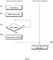
- FIG. 8 is a flowchart showing a mode setting process performed by the control unit 210 included in the setting unit 230.
- the control unit 210 first reads from the hard disk 213 the setting information on the mode set immediately before (step B1).
- control unit 210 causes display unit 180 to display a setting screen for setting a mode (step B2).
- This setting screen is a screen corresponding to the read setting information.
- step B3 when the control unit 210 receives an operation input to the setting screen through the input unit 212 and the next mode is determined (step B3: YES), mode setting information is generated and transmitted to the storage unit 15 and the storage unit 16 (step B4) via the communication unit 211.
- the control units 142 of the accommodation units 15 and 16 store the received setting information in the memory 177 (step B5), and thereafter perform operations in a mode corresponding to the setting information.
- the mode set for the storage unit 15 and the mode set for the storage unit 16 may be the same or different.
- the setting screens 190 shown in FIG. 9A and 9B are displayed on the display unit 180 in the above-described mode setting process, and the mode of the storage units 15 and 16 is determined by an input operation performed by the input unit 212 corresponding to the setting screen 190.
- the setting screen 190 includes a selection item 200 for selecting a mode to be set, a display item 201 for displaying a unit layout 203 of the testing system, and an enter button 202 for accepting an operation for confirming the mode.
- the selection item 200 is a field for displaying a pull-down menu and the like for receiving a selection operation to select either to start storage of the rack R from the first end 130a on the front side of the table 130 by setting a first mode, or to start storage of the rack R from the second end 130b on the rear side of the table 130 by setting a second mode.
- the enter button 202 is a field for accepting a decision operation for confirming the selection in the selection item 200.
- An object 204 changes display position in conjunction with the selection of the selection item 200 is displayed on the unit layout 203 of the display item 201.
- the object 204 is displayed at the corresponding front side position on the collection units 15 and 16 of the unit layout 203.
- the operator operates the operation item 202, it is determined that the first mode is selected as the mode corresponding to the selection in the selection item 200, and the corresponding setting information is transmitted from the second control unit 18 to the storage unit 15 and 16. In this way the storage units 15 and 16 operate in the first mode corresponding to the received setting information.
- the operator selects "rear side" from the pull-down menu of the selection item 200 as shown in FIG.
- the object 204 is displayed at the corresponding rear side position on the collection units 15 and 16 of the unit layout 203.
- the second mode is selected as the mode corresponding to the selection in the selection item 200, and the corresponding setting information is transmitted from the second control unit 18 to the storage unit 15 and 16.
- the storage units 15 and 16 operate in the second mode corresponding to the received setting information.
- the mode of the storage units 15 and 16 is selected using the setting screen 190 in this way.
- the first mode When the first mode is set by the above-described mode setting, storage of a plurality of racks R is started from the first end 130a in the housing units 15 and 16 shown in FIG. 3 . As the number of racks R increases, the racks R are stored from the first end 130a of the table 130 to the rear side.
- the second mode storage of the plurality of racks R is started from the second end 130b in the storage units 15 and 16. As the number of racks R increases, the racks R are stored from the second end 130b of the table 130 to the front side.
- FIG. 10 is a flowchart showing main processing performed by the loading units 10 and 11, the transport unit 12, the storage units 15 and 16, and the second control unit 18.
- FIGS. 1 , 3 , 7 , and 9 description will be made with reference to the reference numerals shown in FIGS. 1 , 3 , 7 , and 9 .
- the loading unit 10 transports the rack R rearward, moves the rack R to the left at the rear end to the loading unit 11 (step T1).
- the loading unit 11 reads the barcodes BC1 and BC2 of the rack R and the container A sent from the loading unit 10 via the rack information reading unit 21 to acquire the identification information of the rack R and the identification information of the container A, and, the identification information of the rack R and the identification information of the container A are transmitted to the second control unit 18 (step T2).
- the loading unit 11 also transports the rack R forward from the rearmost part, so that the rack R is moved to the left at the foremost part to advance the rack R to the transport unit 12 (step T3).
- the control unit 220 of the second control unit 18 determines the transport destination of the rack R based on the received information, and notifies the transport unit 12 and the storage units 15 and 16 (step T4). At this time, the control unit 220 of the second control unit 18 may determine the transport destination of the rack R to control the racks so that the testing load in the two testing units 13 and 14 is distributed and the number of racks accommodated in the two storage units 15 and 16 is dispersed.
- the transport unit 12 sends the rack R from the main transport path 51 to the testing path 53 based on the information relating to the transport destination of the rack R received from the second control unit 18, and sends the rack R to either the testing unit 13 or the testing unit 14; alternatively, a rack R that has been transported to both and has been tested by the testing units 13 and 14 is then transported from the testing path 53 to the main transport path 51 and sent to the storage unit 15 (step T5).
- the storage unit 15 stores the rack in the table 130 or transports the rack R to the storage unit 16 based on the information on the transport destination of the rack R received from the second control unit 18 (step T6).
- the storage unit 16 stores the rack R sent from the storage unit 15 on the table 130 (step T7).
- FIG. 11 is a flowchart of a selection process in the second control unit 18 for selecting which of the storage units 15 and 16 stores the rack.
- the control unit 210 of the second control unit 18 grasps the number N of racks stored in the storage unit 15 (step D1), and grasps the number M of racks R stored in the storage unit 16 (step D2).
- the second control unit 18 compares the storage number N with the storage number M (step D3), and when the storage number N is larger than the storage number M, the storage unit 16 is set as the storage destination of the next rack R (step D4), whereas when the storage number N is smaller than the storage number M, the storage unit 15 is selected as the storage destination of the next rack R (step D5). In this way the number of the racks R stored in the storage units 15 and 16 can be dispersed.
- FIG. 12 shows a flow of a rack R storage process performed by the storage units 15 and 16.
- the control unit 142 of the storage units 15 and 16 reads the setting information related to the mode stored in the memory 177 (step C1), and either determines the first mode or the second mode in accordance with the read setting information (step C2).
- the first transport mechanism 140 is driven to transfer the rack R of the loading unit 100 to the first end 130a (step C4).
- the control unit 142 repeats the transfer of a rack R to the first end 130a each time the loading of a rack R into the loading unit 100 is detected. Since the first transport mechanism 140 sequentially moves the racks R to the first end 130a to the front direction of the table 130 by the push member 150 through this process, a maximum of 25 racks R can be stored by starting the storage of a plurality of racks R from the first end 130a.
- step C5 When the control unit 142 of the storage units 15 and 16 determines that the second mode is to be set and the sensor 123 of the loading unit 100 detects that a rack R is loaded into the loading unit 100 (step C5: YES), the first transport mechanism 140 is driven to transport the rack R of the loading unit 100 to the first end 130a (step C6), and then the second transport mechanism 141 is driven to move the rack R to the second end 130b (step C7). Then, when the sensor 171 of the second transport mechanism 141 detects the pressure when the wall 170 adjacent to the second end 130b is pushed by the rack R (step C8: YES), the control unit 142 stops the drive of the second transport mechanism 141 (step C9).
- the control unit 142 repeats transporting the rack R by the first transport mechanism 140 and the second transport mechanism 141 each time the loading of the rack R into the loading unit 100 is detected.
- the second transport mechanism 141 moves the rack R to the rear of the table 130 by the push member 160 until the rack R abuts the wall 170 on the second end 130b side, or has already moved to the second end 130b side, or moves the rack R until the rack R contacts a rack R (previous rack R) already stored on the second end 130b side and the sensor 171 responds to a rack R pushing against the wall 170. In this way storage of a plurality of racks R is started from the second end 130b, and up to 25 racks R can be stored.
- FIGS. 13A, 13B, 13C, and 13D are plan views schematically showing a change in the storage state of the rack R in the first mode in the storage units 15 and 16.
- a rack R1 first loaded into the loading unit 100 of the storage units 15 and 16 as shown in FIG. 13A is transported to the first end 130a of the table 130 by the push member 150 of the first transport mechanism 140 as shown in FIG. 13B .
- the next rack R2 that has been loaded into the loading unit 100 is pushed by the push member 150 of the first transport mechanism 140 to the front end 130a of the table 130 as shown in FIG. 13D .
- FIGS. 13E, 13F, 13G, and 13H are plan views schematically showing changes in the storage state of the racks R in the storage units 15 and 16 in the second mode.
- a rack R1 which has been first loaded into the loading unit 100 of the storage units 15 and 16 is moved by the push member 150 of the first transport mechanism 140 to the first end 130a of the table 130 as shown in FIG. 13F , and then transported to the second end 130b of the table 130 by the push member 160 of the second transport mechanism 141 as shown in FIG. 13G .
- the sensor 171 of the second transport mechanism 141 detects that the wall 170 has been pressed by the rack R1, and the detection triggers the movement of the push member 160 to stop, whereupon the transport of the rack R1 stops.
- the rack R2 loaded into the loading unit 100 is transported rearward on the table 130 by the push member 150 of the first transport mechanism 140 and the push member 160 of the second transport mechanism 141 so as to move forward one rack from the second end 130b, as shown in FIG. 13H .
- the rack R1 and the wall 170 are pushed by the rack R2, and this is detected by the sensor 171 whereupon the movement of the pushing member 160 is stopped, and the transport of the rack R2 is stopped.
- the storage of plurality of racks R loaded into the loading unit 100 in this manner are stored starting from the second end 130b of the table 130 by the push member 150 of the first transport mechanism 140 and the push member 160 of the second transport mechanism 141 so as to be sequentially moved to the side of the second end 130b of the table 130, and sequentially stored toward the front from the second end 130b of the table 130. Therefore, when the worker W shown in FIG.
- the position at which the storage of the rack R is started can be switched to the front side or the rear side according to the mode of the storage units 15 and 16 by setting the mode via the setting unit 230 shown in FIG. 7 .
- the worker W can remove the rack R from the table 130 more easily since it is possible to set the mode so that the rack R starts storage from a position closer to the work area S of the worker W.
- the first moving mechanism 140 and the second the moving mechanism 141 can be less complex in configuration.
- the first mode workers who are working at the front can easily remove a rack since the first rack to be stored is stopped at the first end 130a, and the racks are arranged rearward (first direction) from the first end 130a toward the center of the table 130.
- the second mode workers who are working at the rear can easily remove a rack since the first rack to be stored is stopped at the second end 130b, and the racks are arranged forward (second direction) from the second end 130b toward the center of the table 130. In this way the work of the worker W removing the rack R from the table 130 can be effectively simplified.
- a rack R can be suitably moved to the table 130 by the moving unit 102 while having a simple configuration since the moving unit 102 includes a first transport mechanism 140 for moving a rack R of the loading unit 100 to the table 130, and a second transport mechanism 141 for moving a rack R on the table 130.
- the first transport mechanism 140 is configured to move the rack R of the loading unit 100 to a first end 130a of the table 130 by moving the rack R in a predetermined direction by a prescribed distance. In this way the movement of the rack R to the table 130 can be performed with a simple control since it is not necessary to control the moving distance of the individual rack R.
- the second transport mechanism 141 is configured to move the rack R on the table 130 until the rack R strikes the wall 170 of the second end 130b of the table 130, or strikes another previously stored rack R on the second end 130b side. In this way the movement of the racks R to the table 130 can be performed with simple controls since it is not necessary to manage the positions of the individual racks R in the memory.
- the storage units 15 and 16 include a sensor 171 that detects pressure on the wall 170 of the second end 130b of the table 130. In this way the movement of the rack R can be easily controlled since the rack R on the table 130 moves until it strikes a wall 170 of the second end 130b of the table 130, or strikes another previously stored rack R on the second end 130b side which is detected by the sensor 171.
- the testing system 1 includes a display unit 180 that displays a setting screen 190 for setting a position at which the rack R starts to be stored; the setting unit 230 changes the position of starting to store the rack R on the table 130 of the second moving unit 102 based on the setting in the setting screen 190 of the display unit 180. In this way the position at which the worker W starts to store the rack R on the table 130 can be suitably performed.
- the setting screen 190 includes a selection item 200 for selecting a position at which the storage of the rack R is started, in this way it is possible for a worker W to suitably select the position at which to start to store the rack R.
- the display of the display item 201 changes in conjunction with the selection in the selection item 200. In this way it easier to understand the rack collection and storage area of the layout 203 of the storage device 240 displayed on the setting screen 190.
- the testing system 1 includes a loading unit 10, testing units 13 and 14, a storage device 240, and a transport unit 12, and is configured to be able to access the containers of the rack R on the transport path.
- the testing system 1 is large and the work area S of the worker W is also likely to be large, the advantage of changing the starting position for storing the racks R to a position close to the work area of the worker W is significant since the position at which the racks R start to be stored on the table 130 can be changed by the setting unit 230 in the testing system 1. Hence, the work of removing the rack R from the table 130 by the worker W can be performed more easily.
- the transport path 50 extends in the left-right direction, connects to the loading unit 100 of the storage device 240, and the table 130 extends in the front-rear direction orthogonal to the transport path 50.
- the work area S of the worker W is divided into the front side and the rear side of the transport path 50.
- the second control unit 18 shown in FIG. 7 includes the setting unit 230 in the above-described embodiment, another unit also may include the setting unit 230.
- the storage units 15 and 16, and the first control unit 17 also may have the function of the setting unit 230, or two or more of the storage units 15 and 16, and the first control unit 17 or the second control unit 18 also may cooperatively have the function of the setting unit 230.
- the setting unit 230 included in the storage device 240 sets the storage mode of the sample rack in the storage device 240, and the control unit 142 of the storage unit 240 controls the first transport mechanism 140 and the second transport mechanism 141 in accordance with these settings.
- the embodiment is not limited to this configuration inasmuch as the setting unit 230 and the control unit 142 may be provided separately from the storage device 240 as shown in FIG. 16 .
- Reference numeral 315 in FIG. 16 indicates a control unit having a separately provided control unit 142, and the control unit 315 includes a hard disk 222 and a communication unit 175a.
- the position at which the storage of the rack R on the table 130 shown in FIG. 13 is started is not limited to the first end 130a or the second end 130b.
- the rack R may be configured to be stored forward from a reference position in front of the table 130.
- the rack R also may be configured to be stored rearward from a reference position in the rear of the table 13.
- the first reference position and the second reference position may be positioned differently on a different horizontal plane, that is, a configuration in which the rack R is transported in the vertical direction may be used, for example.
- the number of areas set as the positions at which storage of the racks R starts is not limited to two, and may be three or more.
- the configurations of the storage units 15 and 16 are not limited to those in the above-described embodiment.
- the storage unit may be configured so that a plurality of racks R are arranged in the left-right direction.
- the storage unit also may include a plurality of loading units, and for example, two loading units 100 may be arranged in parallel in the front-rear direction on the front side or the rear side of the storage unit.
- the loading unit 100 also may be provided on each of the front side and the rear side of the storage unit.
- One loading unit 100 also may be provided near the center of the table 12 in the front-rear direction.
- the configuration and operation of the moving unit 102 are not limited to those of the above-described embodiment; for example, not only the first transport mechanism 140 but also the second transport mechanism 141 may operate in the first mode. In the second mode, the rack R also may be transported only by the first transport mechanism 140.
- the structure of the testing system 1 is not limited to the above-described embodiment.
- the unit layout of the testing system is not limited to the above example, and the numbers and positions of the storage units 15 and 16 can be appropriately changed.
- the number of storage units 15 also may be one, as shown in FIG. 14 .
- the storage units 15 and 16 also may be provided adjacent to the loading unit 10.
- the transport path 50 also may include an outbound path 50a from the loading unit 11 (the loading unit 10 side) toward the testing units 13 and 14 side, and a return path 50b from the testing units 13 and 14 side toward the storage units 15 and 16 side.
- the structure of the transport path 50 can be appropriately changed according to the unit layout of the testing system 1.
- types of samples and types of testings are not particularly limited.
- the present invention is useful when providing a testing system, an storage device, and a rack storage method that can set the storage of a rack according to the situation of a facility.
Abstract
Description
- This application claims priority from prior Japanese Patent Application(s) No.
2019-122304, filed on June 28, 2019 - The present invention relates to a testing system, a storage device, and a rack storage method.
- A sample processing system disclosed in Japanese Patent Application Publication No.
2012-112682 2012-112682 - Patent Document 1: Japanese Patent Application Publication No.
2012-112682 - There are various circumstances in a facility where a testing system is installed, and depending on the installation position of the testing system and the operations of the testing, a user may feel inconvenienced when removing a rack stored in the storage unit.
- In view of the aforesaid problem, the present invention provides a testing system, a storage device, and a rack storage method capable of setting the storage of a rack according to the situation of a facility.
- As shown in
FIG. 1 , the testing system (1) of one aspect of the present invention includes testing devices (testing units 13, 14) for testing a sample of a container (A) held in a rack (R), a transport device (transport unit 12) for transporting a rack (R) that holds a container (A) of a sample tested by a testing device (testing units 13 and 14), and a storage device (240) for storing a rack (R) transported by the transport device (transport unit 12). The storage device (240) includes storage unit (table 130) capable of storing a plurality of racks (R), a setting unit (seeFIG. 7 : 230) for setting a first mode for storing a plurality of racks (R) in the storage unit (table 130) in a first mode and a second mode for storing a plurality of racks in a second mode that is different from the first mode, and a moving unit for moving the rack (R) according to the mode set by the setting unit (seeFIG. 7 : 102). - According to this aspect, the mode of storing a plurality of racks can be set by the setting unit. In this way it is possible to set a suitable rack storage mode in the testing system according to the situation of the facility.
- As shown in
FIG. 16 , the testing system (301) of another aspect of the invention includes a testing device (13, 14) for testing a sample in a container held in a rack, a storage device (340) for storing a rack holding a container of a sample tested by the testing device (13, 14), a transport device (12) for transporting a rack from the testing device (13, 14) to the storage device (340), a setting unit (230) for selecting a storage mode of a rack in the storage device (340), a moving unit (302) for moving the rack transported to the storage device (340) by the transport device (12) to the storage device (340), and a control unit (142) for controlling the moving unit (302) so as to store a rack in the storage device (340) by a first mode when the first mode is selected by the setting unit (230), and controlling the moving unit (302) so as to store a rack in the storage device (340) by a second mode when the second mode is selected by the setting unit (230). - According to this aspect, the mode of storing a plurality of racks can be set by the setting unit. In this way a suitable rack storage mode can be set according to the layout state of the testing device and the transport device in the testing system.
- As shown in
FIG. 1 , the storage device (240) of another aspect of the invention includes is a storage device (240) for storing a rack (R) capable of holding a container (A), and includes storage unit (table 130) capable of storing a plurality of racks (R), a setting unit (seeFIG. 7 : 230) for setting a first mode for starting the storage of a plurality of racks (R) from a first reference position (first end part 130a) of the storage unit (table 130) and a second mode for starting the storage of a plurality of racks from a second reference position (second end part 130b) that is different form the first reference position (first end part 130a) of the storage unit (table 130), and a moving unit (seeFIG. 7 : 102) for moving the rack (R) according to the mode set by the setting unit. - According to this aspect, when the first mode is set by the setting unit, the housing of the plurality of racks is started from the first reference position in the storage unit. When the second mode is set by the setting unit, the storage of the plurality of racks is started from the second reference position in the storage unit. In this way it is possible to set the storage in the storage device so that the storage of the rack is started near the work position of the worker of the storage device.
- As shown in
FIG. 1 , the storage method of another aspect of the invention is a method of storing a rack (R) capable of holding a container (A), and the method includes a step (seeFIG. 8 : B4, B5) of setting a first mode for starting the storage of a plurality of racks from a first reference position (first end 130a) of a storage unit (table 130) capable of storing the racks (R) side by side and a second mode for starting the storage of a plurality of racks from a second reference position (second end 130b) that is different from the first reference position (first end 130a) of the storage unit (table 130), and a step (seeFIG. 12 : C3 to C4, C5 to C9) of moving the rack (R) according to the set mode. - According to this aspect, the storage of the plurality of racks can be set to start from the first reference position or the second reference position by setting the mode. In this way it is possible to set the rack to be started from a position suitable for the operator to remove the rack.
- The testing system, storage device, and rack storage method according to the present invention enables an operator to remove a stored rack appropriately regardless of the installation position and testing operation of the testing system.
-
-
FIG. 1 is a schematic diagram showing a structural example of a testing system in a plan view; -
FIG. 2 is a perspective view showing an example of a rack; -
FIG. 3 is a schematic diagram showing an example of a storage unit in a plan view; -
FIG. 4 is an explanatory diagram showing a structural example of a loading unit; -
FIG. 5 is an explanatory diagram showing a structural example of a first transport mechanism; -
FIG. 6 is an explanatory diagram showing a structural example of a second transport mechanism; -
FIG. 7 is a block diagram of thetesting system 1; -
FIG. 8 is a flowchart of a mode setting process; -
FIG. 9A is an explanatory diagram showing an example of a display of a setting screen when setting a first mode, andFIG. 9B is a diagram showing a setting screen when setting a second mode; -
FIG. 10 is a flowchart showing the main processing in each unit configuring the testing system; -
FIG. 11 is a flowchart of a process of selecting a storage unit for storing a rack in the second control unit; -
FIG. 12 is a flowchart showing a process of storing a rack in a storage unit; -
FIGS. 13A, 13B, 13C, and 13D are plan views showing rack storage state in a storage unit in a first mode; 13E, 13F, 13G, and 13H are plan views showing the rack storage state in a second mode in the storage unit; -
FIG. 14 is a schematic diagram showing another example of the layout of the testing system; -
FIG. 15 is a schematic diagram showing another example of the layout of the testing system; and -
FIG. 16 is a schematic diagram showing another example of the layout of the testing system. - Hereinafter, preferred embodiments of the present invention will be described with reference to the drawings. First, a testing system according to the present embodiment will be described.
FIG. 1 shows a structural example of atesting system 1 in plan view. Areas S1 and S2 indicated by dotted lines inFIG. 1 are examples of a main work area of a worker W who is working in a room where thetesting system 1 is installed. The work area S1 is an area facing one side of thetesting system 1 when thetesting system 1 is viewed in plan view, and the work area S2 is an area facing the other side of thetesting system 1. Hereinafter, the work area S1 side of thetesting system 1 is referred to as "front", and the work area S2 side of thetesting system 1 is referred to as "rear". The right side when thetesting system 1 is viewed from the front side is defined as "right" of thetesting system 1, and the left side when thetesting system 1 is viewed from the front side is defined as "left" of thetesting system 1. - The
testing system 1 includesloading units transport unit 12,testing units storage units first control unit 17, and asecond control unit 18. In the present embodiment, astorage device 240 is configured by thestorage units second control unit 18. - A rack R holding a plurality of containers A containing samples is placed in the
loading unit 10 by an operator. Theloading unit 10 can arrange a plurality of racks R, and is configured each rack R can be sequentially transported to theloading unit 11. The rack R has a plurality of holding holes R1 arranged in a row as shown inFIG. 2 , for example, and can hold a container A inserted in the holding hole R1. A barcode label BL1 is attached to the container A, and a barcode BC1 including the identification information of the container A is printed on the barcode label BL1. A barcode label BL2 is attached to the rack R, and a barcode BC2 including identification information of the rack R is printed on the barcode label BL2. - The
loading unit 10 shown inFIG. 1 has a table 30 in which racks R can be arranged in a front-rear direction. The rack R is arranged on the table 30 in a direction in which the containers A are arranged side by side. Theloading unit 10 moves the rack R disposed at the forefront of the table 30 to the rearmost part in the front-rear direction, and also moves the rack R to the left at the rearmost part, and moves the rack R to theloading unit 11 adjacent to the left side. - The
loading unit 11 has a table 31 on which racks R can be arranged in the front-rear direction. Theloading unit 11 can move the rack R carried to the rearmost position on the table 31 to the forefront position in the front-rear direction. Theloading unit 11 also can move the rack R to the left at the forefront, and can unload the rack R to thetransport unit 12 adjacent to the left side. Theloading unit 11 includes a rackinformation reading unit 21 configured by a barcode reader. The rackinformation reading unit 21 is provided at the rearmost part of theloading unit 11 and reads the barcodes BC1 and BC2 shown inFIG. 2 from the rack R and the container A loaded in theloading unit 11 to acquire identification information of the rack R and the container A. - The
transport unit 12 includes atransport path 50 for transporting the rack R received from theloading unit 11 to thestorage unit 15 that is a predetermined distance on the left side from theloading unit 11. Thetransport path 50 includes amain transport path 51 and twotesting paths 53. Themain transport path 51 is formed in a long linear shape in the left-right direction, and can transport the rack R linearly from theloading unit 11 to thestorage unit 15. The twotesting paths 53 are respectively provided on the rear side of themain transport path 51, and transport the rack R of themain transport path 51 to the front of thetesting unit 13 and the front of thetesting unit 14. Each of the twotesting paths 53 is configured to branch off from themain transport path 51, pass in front of thetesting units main transport path 51. Thetransport unit 12 can transport the rack R loaded from theloading unit 11 to thestorage unit 15 on the left side of themain transport path 51 via one or both testingpaths 53. Thetransport unit 12 is configured to stop the rack R in front of thetesting units testing path 53. - The
testing units testing units transport unit 12 behind thetesting path 53. The sample of the container A held by each rack R transported to thetesting path 53 by thetransport unit 12 is tested by either thetesting unit 13 or thetesting unit 14 or both. Thetesting units rack setting unit 70 and asample extraction arm 71. Therack setting unit 70 is provided on the right side of thetesting units sample extraction arm 71 is configured to access each of the containers A of the rack R of therack setting unit 70 and the container A of the rack R stopped on thetesting path 53. Thesample extraction arm 71 extracts a sample from the container A for examination and introduces the sample into thetesting units - The
storage units transport unit 12. Each rack R loaded in from thetransport unit 12 is stored in one of thestorage units storage units storage units storage units - The
first control unit 17 is a computer that is connected to thetesting units first control unit 17 manages information related to sample testings, and controls the operation of thetesting units first control unit 17 also is communicably connected to thesecond control unit 18 and thehost computer 19 via the in-facility network N. - The
display unit 250 is a display that is connected to thefirst control unit 17, and displays information related to the sample testing and information related to the operation of thetesting units - The
second control unit 18 is disposed on the right side of the carry-inunit 10 and is connected to the carry-inunits transport unit 12, and thestorage units second control unit 18 is a computer for managing the transport state of the rack R and controlling the transport destination of the rack R. Thedisplay unit 180 is a display that is connected to thesecond control unit 18 and displays a setting screen for thestorage units testing system 1. -
FIG. 3 is a schematic diagram showing thestorage units storage units loading unit 100 into which the racks R are loaded, a table 130 capable of storing up to 25 racks R, and a movingunit 102 for moving the racks R loaded into theloading unit 100 to the table 130. - The
loading unit 100 is provided on the front side of thestorage units loading unit 100 is located on an extension of themain transport path 51 of thetransport unit 12, and the rack R is loaded in a direction in which the containers A are lined up in the left-right direction. Theloading unit 100 has a width in the front-rear direction and a length in the left-right direction such that one rack R can be loaded. Theloading unit 100 is provided with asensor 123 that detects that the rack R has been loaded. Thesensor 123 is an infrared sensor. - The
loading unit 100 has abelt conveyor 110 as shown inFIG. 4 . Thebelt conveyor 110 has tworollers 121 arranged side by side in the left-right direction, abelt 120 looped between the tworollers 121, and adrive source 124 connected to therollers 121. The tworollers 121 are rotated by thedrive source 124. Thebelt 120 is rotated by aroller 121. Theloading unit 100 can receive the rack R from thetransport path 50 of thetransport unit 12 by rotating thebelt 120 via thedrive source 124, and can move the rack R to the center of theloading unit 100 in the left-right direction. Theloading unit 100 of thestorage unit 15 can also move the rack R to theloading unit 100 of thestorage unit 16 adjacent to the left side. - As shown in
FIG. 3 , the table 130 is provided on the rear side of thestorage units loading unit 100. The table 130 is formed by a rectangular horizontal plate that is long in the front-rear direction. On the table 130, a maximum of 25 racks R in which the containers A are arranged in the horizontal direction can be stored side by side. Note that the table 130 has a length of 50 cm or more in the front-rear direction. - The moving
unit 102 includes afirst transport mechanism 140, asecond transport mechanism 141, and acontrol unit 142. Thefirst transport mechanism 140 moves the rack R of theloading unit 100 rearward toward the first end (first reference position) 130a on the front side of the table 130. Thesecond transport mechanism 141 moves the rack R on the table 130 rearward toward the second end (second reference position) 130b on the rear side of the table 130. Thecontrol unit 142 is set to the first mode or the second mode in response to an instruction from thesecond control unit 18, and controls thefirst transport mechanism 140 and thesecond transport mechanism 141 according to the set mode. - In the first mode, the moving
unit 102 causes thefirst transport mechanism 140 to start storing a plurality of racks R from thefirst end 130a of the table 130. The first area P1 shown inFIG. 3 indicates an area where three racks R are stored on the front side of the table 130. The first area P1 extends to the rear of the table 130 from thefirst end 130a to a position at which the three racks R are to be stored. As the number of racks R increase, the area in which the racks R are stored extends to the rear side of the table 130. When 25 racks R are stored in the table 130, the racks R are stored in all areas of the table 130 from thefirst end 130a to thesecond end 130b. - In the second mode, the moving
unit 102 causes thefirst transport mechanism 140 and thesecond transport mechanism 141 to start storing a plurality of racks R from thesecond end 130b of the table 130. The second area P2shown inFIG. 3 indicates an area where three racks R are stored on the rear side of the table 130. The second area P2 extends from thesecond end 130b to the front side of the table 130 at a position where the three racks R can be stored. As the number of racks R increase, the area in which the racks R are accommodated extends to the front side of the table 130. When 25 racks R are stored in the table 130, the racks R are stored in all areas of the table 130 from thesecond end 130b to thefirst end 130a. -
FIG. 5 is a plan view showing a state in which thefirst transport mechanism 140 is removed and exposed from thestorage units first transport mechanism 140 includes aflat push member 150 that is long in the left-right direction, and adriving unit 151 that moves thepush member 150 in the front-rear direction. Thedrive unit 151 is configured to convert the rotation of the motor into the forward and backward movement of thepush member 150 via a gear. Thepush member 150 is disposed with the position Q1 on the front side of theloading unit 100 as an initial position. The drive of thedrive unit 151 is controlled by thecontrol unit 142. Thefirst transport mechanism 140 moves thepush member 150 from the preset initial position Q1 to a position Q2 which is a predetermined distance away from the preset initial position Q1 by the drivingunit 151 controlled by thecontrol unit 142 such that the rack R can be pushed to thefirst end 130a by thepush member 150. -
FIG. 6 is a plan view showing thesecond transport mechanism 141 in a state in which the table 130 is removed and exposed from thestorage units second transport mechanism 141 includes twopush members 160 disposed on both sides of the table 130 in the left-right direction, aslider 161 supporting the twopush members 160, arail 162 provided with a length in the front-rear direction over bothends driving mechanism 163 for moving theslider 161 in the front-rear direction along therail 162. Thepush member 160 is arranged with a position Q3 behind theloading unit 100 and forward of thefirst end 130a as an initial position. Thedriving mechanism 163 includes abelt 164 spanning both ends 130a and 130b of the table 130, and adriving unit 165 that rotates thebelt 164. Theslider 161 is attached to thebelt 164 so as to move in the front-rear direction by the rotation of thebelt 164. The drive of thedriving unit 165 is controlled by thecontrol unit 142. Thesecond transport mechanism 141 can move thepush member 160 fixed to theslider 161 via thebelt 164 in the front-rear direction via thedriving unit 165 controlled by thecontrol unit 142. Thesecond transport mechanism 141 moves thepush member 160 from the initial position Q3 to a position immediately in front of thewall 170 on thesecond end 130b side through thefirst end 130a of the table 130, so that the rack R loaded at thefirst end 130a can be moved toward thesecond end 130b. Each of the twopush members 160 can transition between an initial state α1 and a retracted state α2, and is configured to return from the retracted state α2 to the initial state α1 by a spring. When the rack R moves from theloading unit 100 to thefirst end 130a, thepush member 160 is pushed by the rack R and rotationally moves from the initial state α1 to the retracted state α2 to retreat from the track of the rack R. Then, when the rack R reaches thefirst end 130a, the rack R returns from the retracted state α2 to the initial state α1, and the rack R can be transported rearward. - The
second transport mechanism 141 also includes asensor 171 for detecting the presence or absence of pressure on thewall 170 on thesecond end 130b side. Thesensor 171 detects the pressure when thewall 170 on thesecond end 130b side moves rearward. Information detected by thesensor 171 is output to thecontrol unit 142, and thecontrol unit 142 can stop the movement of thepush member 160 by stopping thedriving unit 165 based on the information. Therefore, thesecond transport mechanism 141 can move the rack R on the table 130 rearward by thepush member 160, and continue to move the rack R until thesensor 170 detects the pressure. -
FIG. 7 is a block diagram showing a structure related to the control of each unit configuring thetesting system 1. Thestorage unit 15 includes acommunication unit 175 in addition to thecontrol unit 142, thebelt conveyor 110, thesensor 123, thefirst transport mechanism 140, and thesecond transport mechanism 141. Thecommunication unit 175 is configured to be able to communicate with thesecond control unit 18. Thecontrol unit 142, thefirst transport mechanism 140, and thesecond transport mechanism 141 configure the movingunit 102. Thecontrol unit 142 includes aCPU 176 and amemory 177; theCPU 176 executes a program stored in thememory 177, so that the rack R can be stored in thestorage unit 15. Thememory 177 includes a storage medium such as a ROM, a RAM, and a memory card, and stores a program for executing a process of storing the rack R, as well as an execution file of the program and data formed by executing the program, as well as data such as setting information acquired from thesecond control unit 18 via thecommunication unit 175. - The
first control unit 17 includes acontrol unit 220, acommunication unit 221, ahard disk 222, aninput unit 225, and adisplay unit 250. Thecommunication unit 221 is configured to be able to communicate with thetesting units communication unit 221 is configured to be able to communicate with thesecond control unit 18 and thehost computer 19 via the network N. Thehard disk 222 stores programs for executing various processes, and various data. Thecontrol unit 220 includes aCPU 223 and amemory 224, and executes various programs by reading a program stored in thehard disk 222 by theCPU 223, and developing the program in thememory 224. Thememory 224 stores an execution file of the program, data formed by executing the program, and data obtained from theexternal testing units host computer 19, and thesecond control unit 18 via thecommunication unit 221. Thecontrol unit 220 acquires the sample ID of the sample to be tested by thetesting units host computer 19 regarding the measurement order. Thecontrol unit 220 performs an analysis based on the measurement results performed by thetesting units host computer 19. The measurement order means a measurement item registered in advance in association with the sample ID. - The
second control unit 18 includes acontrol unit 210, acommunication unit 211, ahard disk 213, aninput unit 212, and adisplay unit 180. Thecommunication unit 211 can communicate with theloading units transport unit 12, thestorage units first control unit 17. Thecommunication unit 211 also can communicate with thefirst control unit 17 and thehost computer 19 via the network N. Thehard disk 213 stores programs for executing various processes and various setting information. Thecontrol unit 210 includes aCPU 214 and amemory 215, and executes a program by reading the program stored in thehard disk 213 by theCPU 214, and developing the program in thememory 215. Thememory 215 stores an execution file of the program, data produced by executing the program, and data obtained from theexternal loading units transport unit 12, thestorage units first control unit 17, and thehost computer 19 via thecommunication unit 211. By executing the program, thecontrol unit 210 acquires signals of the detected passage of the rack R at a predetermined position from each of theloading units transport unit 12, and thestorage units communication unit 211,and sends and receives signals between each of the units so as to indicate the transport destination of the rack R. - The
control unit 210 of thesecond control unit 18 configures asetting unit 230 together with thecommunication unit 211 and thehard disk 213. Thesetting unit 230 realizes a function of setting a first mode and a second mode in thestorage units testing system 1 is in a state in which various settings can be changed. -
FIG. 8 is a flowchart showing a mode setting process performed by thecontrol unit 210 included in thesetting unit 230. Hereinafter, description will be made with reference to the reference numerals shown inFIG. 7 . In the mode setting process, thecontrol unit 210 first reads from thehard disk 213 the setting information on the mode set immediately before (step B1). Next,control unit 210 causesdisplay unit 180 to display a setting screen for setting a mode (step B2). This setting screen is a screen corresponding to the read setting information. Then, when thecontrol unit 210 receives an operation input to the setting screen through theinput unit 212 and the next mode is determined (step B3: YES), mode setting information is generated and transmitted to thestorage unit 15 and the storage unit 16 (step B4) via thecommunication unit 211. In this way thecontrol units 142 of theaccommodation units storage unit 15 and the mode set for thestorage unit 16 may be the same or different. - The setting screens 190 shown in
FIG. 9A and 9B are displayed on thedisplay unit 180 in the above-described mode setting process, and the mode of thestorage units input unit 212 corresponding to thesetting screen 190. Thesetting screen 190 includes aselection item 200 for selecting a mode to be set, adisplay item 201 for displaying aunit layout 203 of the testing system, and anenter button 202 for accepting an operation for confirming the mode. Theselection item 200 is a field for displaying a pull-down menu and the like for receiving a selection operation to select either to start storage of the rack R from thefirst end 130a on the front side of the table 130 by setting a first mode, or to start storage of the rack R from thesecond end 130b on the rear side of the table 130 by setting a second mode. Theenter button 202 is a field for accepting a decision operation for confirming the selection in theselection item 200. Anobject 204 changes display position in conjunction with the selection of theselection item 200 is displayed on theunit layout 203 of thedisplay item 201. - When the operator selects "front side" from the pull-down menu of the
selection item 200 as shown inFIG. 9A , theobject 204 is displayed at the corresponding front side position on thecollection units unit layout 203. Next, when the operator operates theoperation item 202, it is determined that the first mode is selected as the mode corresponding to the selection in theselection item 200, and the corresponding setting information is transmitted from thesecond control unit 18 to thestorage unit storage units selection item 200 as shown inFIG. 9B , theobject 204 is displayed at the corresponding rear side position on thecollection units unit layout 203. Next, when the operator operates theoperation item 202, it is determined that the second mode is selected as the mode corresponding to the selection in theselection item 200, and the corresponding setting information is transmitted from thesecond control unit 18 to thestorage unit storage units storage units setting screen 190 in this way. - When the first mode is set by the above-described mode setting, storage of a plurality of racks R is started from the
first end 130a in thehousing units FIG. 3 . As the number of racks R increases, the racks R are stored from thefirst end 130a of the table 130 to the rear side. When the second mode is set, storage of the plurality of racks R is started from thesecond end 130b in thestorage units second end 130b of the table 130 to the front side. - Next, main processing of each unit from loading to storage of the rack R in the
testing system 1 configured as described above will be described.FIG. 10 is a flowchart showing main processing performed by theloading units transport unit 12, thestorage units second control unit 18. Hereinafter, description will be made with reference to the reference numerals shown inFIGS. 1 ,3 ,7 , and9 . - When a rack R holding a plurality of containers A containing untested samples is to be loaded, the
loading unit 10 transports the rack R rearward, moves the rack R to the left at the rear end to the loading unit 11 (step T1). Theloading unit 11 reads the barcodes BC1 and BC2 of the rack R and the container A sent from theloading unit 10 via the rackinformation reading unit 21 to acquire the identification information of the rack R and the identification information of the container A, and, the identification information of the rack R and the identification information of the container A are transmitted to the second control unit 18 (step T2). Theloading unit 11 also transports the rack R forward from the rearmost part, so that the rack R is moved to the left at the foremost part to advance the rack R to the transport unit 12 (step T3). Thecontrol unit 220 of thesecond control unit 18 determines the transport destination of the rack R based on the received information, and notifies thetransport unit 12 and thestorage units 15 and 16 (step T4). At this time, thecontrol unit 220 of thesecond control unit 18 may determine the transport destination of the rack R to control the racks so that the testing load in the twotesting units storage units transport unit 12 sends the rack R from themain transport path 51 to thetesting path 53 based on the information relating to the transport destination of the rack R received from thesecond control unit 18, and sends the rack R to either thetesting unit 13 or thetesting unit 14; alternatively, a rack R that has been transported to both and has been tested by thetesting units testing path 53 to themain transport path 51 and sent to the storage unit 15 (step T5). Thestorage unit 15 stores the rack in the table 130 or transports the rack R to thestorage unit 16 based on the information on the transport destination of the rack R received from the second control unit 18 (step T6). Thestorage unit 16 stores the rack R sent from thestorage unit 15 on the table 130 (step T7). - When the
second control unit 18 determines which of thestorage units FIG. 11 can be used.FIG. 11 is a flowchart of a selection process in thesecond control unit 18 for selecting which of thestorage units control unit 210 of thesecond control unit 18 grasps the number N of racks stored in the storage unit 15 (step D1), and grasps the number M of racks R stored in the storage unit 16 (step D2). Then, thesecond control unit 18 compares the storage number N with the storage number M (step D3), and when the storage number N is larger than the storage number M, thestorage unit 16 is set as the storage destination of the next rack R (step D4), whereas when the storage number N is smaller than the storage number M, thestorage unit 15 is selected as the storage destination of the next rack R (step D5). In this way the number of the racks R stored in thestorage units -
FIG. 12 shows a flow of a rack R storage process performed by thestorage units control unit 142 of thestorage units - When the
control unit 142 of thestorage units sensor 123 of theloading unit 100 detects that the rack R is loaded into the loading unit 100 (step C3: YES), thefirst transport mechanism 140 is driven to transfer the rack R of theloading unit 100 to thefirst end 130a (step C4). Thecontrol unit 142 repeats the transfer of a rack R to thefirst end 130a each time the loading of a rack R into theloading unit 100 is detected. Since thefirst transport mechanism 140 sequentially moves the racks R to thefirst end 130a to the front direction of the table 130 by thepush member 150 through this process, a maximum of 25 racks R can be stored by starting the storage of a plurality of racks R from thefirst end 130a. - When the
control unit 142 of thestorage units sensor 123 of theloading unit 100 detects that a rack R is loaded into the loading unit 100 (step C5: YES), thefirst transport mechanism 140 is driven to transport the rack R of theloading unit 100 to thefirst end 130a (step C6), and then thesecond transport mechanism 141 is driven to move the rack R to thesecond end 130b (step C7). Then, when thesensor 171 of thesecond transport mechanism 141 detects the pressure when thewall 170 adjacent to thesecond end 130b is pushed by the rack R (step C8: YES), thecontrol unit 142 stops the drive of the second transport mechanism 141 (step C9). - The
control unit 142 repeats transporting the rack R by thefirst transport mechanism 140 and thesecond transport mechanism 141 each time the loading of the rack R into theloading unit 100 is detected. Thesecond transport mechanism 141 moves the rack R to the rear of the table 130 by thepush member 160 until the rack R abuts thewall 170 on thesecond end 130b side, or has already moved to thesecond end 130b side, or moves the rack R until the rack R contacts a rack R (previous rack R) already stored on thesecond end 130b side and thesensor 171 responds to a rack R pushing against thewall 170. In this way storage of a plurality of racks R is started from thesecond end 130b, and up to 25 racks R can be stored. -
FIGS. 13A, 13B, 13C, and 13D are plan views schematically showing a change in the storage state of the rack R in the first mode in thestorage units loading unit 100 of thestorage units FIG. 13A is transported to thefirst end 130a of the table 130 by thepush member 150 of thefirst transport mechanism 140 as shown inFIG. 13B . Next, as shown inFIG. 13C , the next rack R2 that has been loaded into theloading unit 100 is pushed by thepush member 150 of thefirst transport mechanism 140 to thefront end 130a of the table 130 as shown inFIG. 13D . In this way a previously transported rack R1 is pushed by the rack R2, and moves to the rear position adjacent to the rack R1 in the first area P1. The plurality of racks R thus loaded into theloading unit 100 are transported to thefirst end 130a by thepush member 150 of thefirst transport mechanism 140, and push the existing rack R on the table 130 rearward. In this way the storage of the plurality of racks R starts from thefirst end 130a, such that the racks R are sequentially moved to thefirst end 130a, and are gathered and stored in rearward from thefirst end 130a of the table 130. Therefore, when a worker W shown inFIG. 1 predominantly performs work in the work area S1 to the front of thestorage units storage units storage units housing units -
FIGS. 13E, 13F, 13G, and 13H are plan views schematically showing changes in the storage state of the racks R in thestorage units FIG. 13E , a rack R1 which has been first loaded into theloading unit 100 of thestorage units push member 150 of thefirst transport mechanism 140 to thefirst end 130a of the table 130 as shown inFIG. 13F , and then transported to thesecond end 130b of the table 130 by thepush member 160 of thesecond transport mechanism 141 as shown inFIG. 13G . At this time, thesensor 171 of thesecond transport mechanism 141 detects that thewall 170 has been pressed by the rack R1, and the detection triggers the movement of thepush member 160 to stop, whereupon the transport of the rack R1 stops. Next, the rack R2 loaded into theloading unit 100 is transported rearward on the table 130 by thepush member 150 of thefirst transport mechanism 140 and thepush member 160 of thesecond transport mechanism 141 so as to move forward one rack from thesecond end 130b, as shown inFIG. 13H . At this time, since the rack R1 and thewall 170 are pushed by the rack R2, and this is detected by thesensor 171 whereupon the movement of the pushingmember 160 is stopped, and the transport of the rack R2 is stopped. The storage of plurality of racks R loaded into theloading unit 100 in this manner are stored starting from thesecond end 130b of the table 130 by thepush member 150 of thefirst transport mechanism 140 and thepush member 160 of thesecond transport mechanism 141 so as to be sequentially moved to the side of thesecond end 130b of the table 130, and sequentially stored toward the front from thesecond end 130b of the table 130. Therefore, when the worker W shown inFIG. 1 predominantly performs work in the work area S2 to the rear of thestorage units storage units storage units storage units - According to the present embodiment described above, the position at which the storage of the rack R is started can be switched to the front side or the rear side according to the mode of the
storage units setting unit 230 shown inFIG. 7 . Hence, the worker W can remove the rack R from the table 130 more easily since it is possible to set the mode so that the rack R starts storage from a position closer to the work area S of the worker W. - As shown in
FIG. 3 , since thefirst end 130a and thesecond end 130b are in the same horizontal plane area, it is unnecessary to move the rack R up and down, and the first movingmechanism 140 and the second the movingmechanism 141 can be less complex in configuration. In the case of the first mode, workers who are working at the front can easily remove a rack since the first rack to be stored is stopped at thefirst end 130a, and the racks are arranged rearward (first direction) from thefirst end 130a toward the center of the table 130. Similarly, in the case of the second mode, workers who are working at the rear can easily remove a rack since the first rack to be stored is stopped at thesecond end 130b, and the racks are arranged forward (second direction) from thesecond end 130b toward the center of the table 130. In this way the work of the worker W removing the rack R from the table 130 can be effectively simplified. - A rack R can be suitably moved to the table 130 by the moving
unit 102 while having a simple configuration since the movingunit 102 includes afirst transport mechanism 140 for moving a rack R of theloading unit 100 to the table 130, and asecond transport mechanism 141 for moving a rack R on the table 130. - The
first transport mechanism 140 is configured to move the rack R of theloading unit 100 to afirst end 130a of the table 130 by moving the rack R in a predetermined direction by a prescribed distance. In this way the movement of the rack R to the table 130 can be performed with a simple control since it is not necessary to control the moving distance of the individual rack R. - The
second transport mechanism 141 is configured to move the rack R on the table 130 until the rack R strikes thewall 170 of thesecond end 130b of the table 130, or strikes another previously stored rack R on thesecond end 130b side. In this way the movement of the racks R to the table 130 can be performed with simple controls since it is not necessary to manage the positions of the individual racks R in the memory. - The
storage units sensor 171 that detects pressure on thewall 170 of thesecond end 130b of the table 130. In this way the movement of the rack R can be easily controlled since the rack R on the table 130 moves until it strikes awall 170 of thesecond end 130b of the table 130, or strikes another previously stored rack R on thesecond end 130b side which is detected by thesensor 171. - As shown in
FIG. 9 , thetesting system 1 includes adisplay unit 180 that displays asetting screen 190 for setting a position at which the rack R starts to be stored; thesetting unit 230 changes the position of starting to store the rack R on the table 130 of the second movingunit 102 based on the setting in thesetting screen 190 of thedisplay unit 180. In this way the position at which the worker W starts to store the rack R on the table 130 can be suitably performed. - The
setting screen 190 includes aselection item 200 for selecting a position at which the storage of the rack R is started, in this way it is possible for a worker W to suitably select the position at which to start to store the rack R. - The display of the
display item 201 changes in conjunction with the selection in theselection item 200. In this way it easier to understand the rack collection and storage area of thelayout 203 of thestorage device 240 displayed on thesetting screen 190. - As shown in
FIG. 1 , thetesting system 1 includes aloading unit 10,testing units storage device 240, and atransport unit 12, and is configured to be able to access the containers of the rack R on the transport path. Although thetesting system 1 is large and the work area S of the worker W is also likely to be large, the advantage of changing the starting position for storing the racks R to a position close to the work area of the worker W is significant since the position at which the racks R start to be stored on the table 130 can be changed by thesetting unit 230 in thetesting system 1. Hence, the work of removing the rack R from the table 130 by the worker W can be performed more easily. - In the
testing system 1, thetransport path 50 extends in the left-right direction, connects to theloading unit 100 of thestorage device 240, and the table 130 extends in the front-rear direction orthogonal to thetransport path 50. In this case, the work area S of the worker W is divided into the front side and the rear side of thetransport path 50. In such atesting system 1, being able to change the starting position for storing the rack R on the table 130 is greatly advantageous. - Although the preferred embodiments of the present invention have been described above with reference to the accompanying drawings, the present invention is not limited to such examples. It is clear that those skilled in the art can conceive various changes or modifications within the scope of the invention described in the claims, and it is to be understood that these changes and modifications naturally belong to the technical scope of the present invention.
- For example, although the
second control unit 18 shown inFIG. 7 includes thesetting unit 230 in the above-described embodiment, another unit also may include thesetting unit 230. For example, thestorage units first control unit 17 also may have the function of thesetting unit 230, or two or more of thestorage units first control unit 17 or thesecond control unit 18 also may cooperatively have the function of thesetting unit 230. - As shown in
FIG. 7 , in the above embodiment, thesetting unit 230 included in thestorage device 240 sets the storage mode of the sample rack in thestorage device 240, and thecontrol unit 142 of thestorage unit 240 controls thefirst transport mechanism 140 and thesecond transport mechanism 141 in accordance with these settings. However, the embodiment is not limited to this configuration inasmuch as thesetting unit 230 and thecontrol unit 142 may be provided separately from thestorage device 240 as shown inFIG. 16 .Reference numeral 315 inFIG. 16 indicates a control unit having a separately providedcontrol unit 142, and thecontrol unit 315 includes ahard disk 222 and acommunication unit 175a. - The position at which the storage of the rack R on the table 130 shown in
FIG. 13 is started is not limited to thefirst end 130a or thesecond end 130b. For example, the rack R may be configured to be stored forward from a reference position in front of the table 130. The rack R also may be configured to be stored rearward from a reference position in the rear of the table 13. The first reference position and the second reference position may be positioned differently on a different horizontal plane, that is, a configuration in which the rack R is transported in the vertical direction may be used, for example. The number of areas set as the positions at which storage of the racks R starts is not limited to two, and may be three or more. - The configurations of the
storage units loading units 100 may be arranged in parallel in the front-rear direction on the front side or the rear side of the storage unit. Theloading unit 100 also may be provided on each of the front side and the rear side of the storage unit. Oneloading unit 100 also may be provided near the center of the table 12 in the front-rear direction. The configuration and operation of the movingunit 102 are not limited to those of the above-described embodiment; for example, not only thefirst transport mechanism 140 but also thesecond transport mechanism 141 may operate in the first mode. In the second mode, the rack R also may be transported only by thefirst transport mechanism 140. - The structure of the
testing system 1 is not limited to the above-described embodiment. For example, the unit layout of the testing system is not limited to the above example, and the numbers and positions of thestorage units storage units 15 also may be one, as shown inFIG. 14 . As shown inFIG. 15 , thestorage units loading unit 10. In this case, thetransport path 50 also may include anoutbound path 50a from the loading unit 11 (theloading unit 10 side) toward thetesting units return path 50b from thetesting units storage units transport path 50 can be appropriately changed according to the unit layout of thetesting system 1. In the storage device and the testing system according to the present invention, types of samples and types of testings are not particularly limited. - The present invention is useful when providing a testing system, an storage device, and a rack storage method that can set the storage of a rack according to the situation of a facility.
-
- 1
- Testing system
- 10
- Loading unit
- 12
- Transport unit
- 13, 14
- Testing unit
- 15, 16
- Storage unit
- 17
- First control unit
- 18
- Second control unit
- 100
- Loading unit
- 102
- Transport unit
- 130
- Table (storage unit)
- 230
- Setting unit
- 240
- Storage device
- A
- Container
- R
- Rack
- P1
- First area
- P2
- Second area
Claims (15)
- A testing system comprising:a testing device for testing a sample in a container held in a rack;a transport device for transporting a rack that holds the containers of samples that have been tested by the testing device; anda storage device for storing the rack transported by the transport device;wherein the storage device comprises:a storage unit capable of accommodating a plurality of racks;a setting unit for setting a first mode for storing a plurality of racks in the storage unit by a first manner, and a second mode for storing a plurality of racks by a second manner that is different from the first manner; anda moving unit for moving a rack in accordance with the mode set by the setting unit.
- The testing system according to claim 1, wherein
the moving unit stores a rack from a first position in the first mode, and stores a rack from a second position in the second mode. - The testing system according to claim 2, wherein
the first position and the second position are on the same horizontal plane. - The testing system according to claim 2 or 3, wherein
the moving unit moves a rack so that a plurality of racks are stored in a first direction from the first position in the first mode, and moves a rack so that a plurality of racks are stored in a second direction that is opposite from the first direction from the second position in the second mode. - The testing system according to claim 4, wherein the first direction and the second direction are both directions toward a center of the storage unit.
- The testing system according to claim 2 or 3, wherein
the moving unit comprises:a first transport mechanism for moving a rack to be stored in the storage unit to the storage unit; anda second moving unit for moving a rack of the storage unit in the storage unit. - The testing system according to claim 6, wherein
the first transport mechanism is configured to store a plurality of racks from the first position in a first direction by moving each of the plurality of racks to the first reference position. - The testing system according to claim 6 or 7, wherein
the second transport mechanism is configured to store a plurality of racks from the second position in a second direction that is opposite of the first direction by moving the plurality of racks until they abut another previously stored rack or a wall adjacent to the second reference position. - The testing system according to claim 8, further comprising:
a sensor for detecting a push from a rack at a second position of the storage unit. - The testing system according to any one of claims 2 to 9, further comprising:a display unit for displaying a setting screen for setting the mode;wherein the setting unit sets a mode selected by an input operation based on the setting screen.
- The testing system according to claim 10, whereinthe setting screen comprises selection items for selecting the first mode and the second mode; andthe setting unit sets a mode based on the selection of the selection item.
- A testing system comprising:a testing device for testing a sample in a container held in a rack;a storage device for storing a rack holding a container of a sample that has been tested by the testing device;a transport device for transporting a rack from the testing device to the storage device;a setting unit for setting a storage mode of the sample rack in a storage unit;a moving unit for moving a rack transported to the storage device by the transport device to a storage unit; anda control unit for controlling the moving unit so as to store a rack in the storage unit by a first manner when a first mode has been set by the setting unit, and controlling the moving unit so as to store a rack in the storage unit by a second manner when a second mode has been set by the setting unit.
- A storage device that stores a rack capable of holding one or more containers, the storage device comprising:a storage unit capable of accommodating a plurality of racks;a setting unit for setting a first mode for starting the storage of a plurality of racks from a first position of the storage unit, and a second mode for starting the storage of a plurality of racks from a second position that is different from the first position of the storage unit; anda moving unit for moving the rack in accordance with the mode set by the setting unit.
- A method for storing a rack capable of holding one or more containers, the method comprising:setting a first mode for starting the storage of a plurality of racks are from a first position of a storage unit in which racks can be arranged side by side, and a second mode for starting storage of a plurality of racks from a second position that is different from the first position of the storage unit; andmoving a rack according to the mode set.
- The method according to claim 14, wherein
the rack is moved such that a plurality of racks are stored from a first position in the first mode, and the rack is moved such that the plurality of rack are stored from a second position in the second mode.
Applications Claiming Priority (1)
| Application Number | Priority Date | Filing Date | Title |
|---|---|---|---|
| JP2019122304A JP7285710B2 (en) | 2019-06-28 | 2019-06-28 | Inspection system, storage device, and rack storage method |
Publications (1)
| Publication Number | Publication Date |
|---|---|
| EP3809134A1 true EP3809134A1 (en) | 2021-04-21 |
Family
ID=71143504
Family Applications (1)
| Application Number | Title | Priority Date | Filing Date |
|---|---|---|---|
| EP20181933.1A Pending EP3809134A1 (en) | 2019-06-28 | 2020-06-24 | Testing system, storage device, and rack storage method |
Country Status (4)
| Country | Link |
|---|---|
| US (1) | US20200408793A1 (en) |
| EP (1) | EP3809134A1 (en) |
| JP (1) | JP7285710B2 (en) |
| CN (1) | CN112147349A (en) |
Citations (4)
| Publication number | Priority date | Publication date | Assignee | Title |
|---|---|---|---|---|
| EP2299281A2 (en) * | 2009-09-16 | 2011-03-23 | Sysmex Corporation | Rack collecting unit and sample processing apparatus |
| EP2423689A1 (en) * | 2009-04-20 | 2012-02-29 | Hitachi High-Technologies Corporation | Automatic analysis device |
| JP2012112682A (en) | 2010-11-19 | 2012-06-14 | Sysmex Corp | Specimen conveyance system, specimen processing system and control device |
| EP2724778A1 (en) * | 2012-10-24 | 2014-04-30 | F.Hoffmann-La Roche Ag | System and method for locating sample vessels |
Family Cites Families (13)
| Publication number | Priority date | Publication date | Assignee | Title |
|---|---|---|---|---|
| JP3336894B2 (en) * | 1997-01-29 | 2002-10-21 | 株式会社日立製作所 | Automatic analyzer |
| JP3931110B2 (en) * | 2002-05-29 | 2007-06-13 | 株式会社日立ハイテクノロジーズ | Automatic analyzer |
| JP4519667B2 (en) * | 2005-01-31 | 2010-08-04 | シスメックス株式会社 | Sample rack transport device |
| JP4546863B2 (en) * | 2005-03-28 | 2010-09-22 | シスメックス株式会社 | Transport device |
| JP2010151708A (en) * | 2008-12-26 | 2010-07-08 | Hitachi High-Technologies Corp | Automatic analyzer |
| JP5315044B2 (en) * | 2008-12-26 | 2013-10-16 | シスメックス株式会社 | Sample testing equipment |
| JP5439107B2 (en) | 2009-09-30 | 2014-03-12 | シスメックス株式会社 | Rack collection unit |
| US8196591B2 (en) * | 2009-10-01 | 2012-06-12 | Kiss Nail Products, Inc. | Artificial eyelash and method for applying same |
| JP5787574B2 (en) * | 2011-03-30 | 2015-09-30 | シスメックス株式会社 | Sample analysis system |
| JP6535486B2 (en) * | 2015-03-18 | 2019-06-26 | シスメックス株式会社 | Sample measurement system and method for searching tray specific information |
| JP6508993B2 (en) * | 2015-03-18 | 2019-05-08 | シスメックス株式会社 | Sample measurement system and rack delivery method |
| EP3474018B1 (en) | 2017-10-18 | 2020-07-22 | Roche Diagnostics GmbH | A method to store sample tubes in a laboratory storage and retrieval system |
| JP6940838B2 (en) * | 2017-11-01 | 2021-09-29 | カミ商事株式会社 | Feather powder manufacturing method and feather powder manufacturing equipment |
-
2019
- 2019-06-28 JP JP2019122304A patent/JP7285710B2/en active Active
-
2020
- 2020-06-19 CN CN202010563500.1A patent/CN112147349A/en active Pending
- 2020-06-24 EP EP20181933.1A patent/EP3809134A1/en active Pending
- 2020-06-26 US US16/913,112 patent/US20200408793A1/en active Pending
Patent Citations (4)
| Publication number | Priority date | Publication date | Assignee | Title |
|---|---|---|---|---|
| EP2423689A1 (en) * | 2009-04-20 | 2012-02-29 | Hitachi High-Technologies Corporation | Automatic analysis device |
| EP2299281A2 (en) * | 2009-09-16 | 2011-03-23 | Sysmex Corporation | Rack collecting unit and sample processing apparatus |
| JP2012112682A (en) | 2010-11-19 | 2012-06-14 | Sysmex Corp | Specimen conveyance system, specimen processing system and control device |
| EP2724778A1 (en) * | 2012-10-24 | 2014-04-30 | F.Hoffmann-La Roche Ag | System and method for locating sample vessels |
Also Published As
| Publication number | Publication date |
|---|---|
| US20200408793A1 (en) | 2020-12-31 |
| CN112147349A (en) | 2020-12-29 |
| JP7285710B2 (en) | 2023-06-02 |
| JP2021009054A (en) | 2021-01-28 |
Similar Documents
| Publication | Publication Date | Title |
|---|---|---|
| JP5715378B2 (en) | Sample processing system | |
| JP5530613B2 (en) | Sample processing system and sample transport system | |
| US9505005B2 (en) | Tube sorter, sample processing system, and sample transporting method | |
| JP5339853B2 (en) | Sample processing system | |
| JP5787574B2 (en) | Sample analysis system | |
| JP5736128B2 (en) | Sample processing system, rack transport system, sample processing method, and rack transport method | |
| JP6850545B2 (en) | Specimen analysis system | |
| JP5727219B2 (en) | Sample analyzer and sample analysis system | |
| EP2299281B1 (en) | Rack collecting unit and sample processing apparatus | |
| JP5485767B2 (en) | Sample rack transport system | |
| JP6535486B2 (en) | Sample measurement system and method for searching tray specific information | |
| US20110076194A1 (en) | Rack collecting unit and sample processing apparatus | |
| JP5638823B2 (en) | Sample processing system | |
| JP3029330B2 (en) | Automatic chemical analyzer | |
| JP6508993B2 (en) | Sample measurement system and rack delivery method | |
| CN110967504A (en) | Analyzer and sample recovery method thereof, storage medium | |
| US20130260412A1 (en) | Sample processing apparatus, sample analyzer, sample analyzing system, sample processing system and sample processing method | |
| EP3809134A1 (en) | Testing system, storage device, and rack storage method | |
| JP3589020B2 (en) | Sample processing system | |
| JP5748456B2 (en) | Sample transport system, sample processing system and control device | |
| EP3206035A1 (en) | Automatic analysis system | |
| JPH095332A (en) | Rack for classifying specimen | |
| JP3423106B2 (en) | Sample sorting apparatus and sample sorting method | |
| JPH08285855A (en) | Specimen sorting system | |
| WO2015189892A1 (en) | Automatic analysis system |
Legal Events
| Date | Code | Title | Description |
|---|---|---|---|
| PUAI | Public reference made under article 153(3) epc to a published international application that has entered the european phase |
Free format text: ORIGINAL CODE: 0009012 |
|
| STAA | Information on the status of an ep patent application or granted ep patent |
Free format text: STATUS: THE APPLICATION HAS BEEN PUBLISHED |
|
| AK | Designated contracting states |
Kind code of ref document: A1 Designated state(s): AL AT BE BG CH CY CZ DE DK EE ES FI FR GB GR HR HU IE IS IT LI LT LU LV MC MK MT NL NO PL PT RO RS SE SI SK SM TR |
|
| AX | Request for extension of the european patent |
Extension state: BA ME |
|
| STAA | Information on the status of an ep patent application or granted ep patent |
Free format text: STATUS: REQUEST FOR EXAMINATION WAS MADE |
|
| 17P | Request for examination filed |
Effective date: 20211018 |
|
| RBV | Designated contracting states (corrected) |
Designated state(s): AL AT BE BG CH CY CZ DE DK EE ES FI FR GB GR HR HU IE IS IT LI LT LU LV MC MK MT NL NO PL PT RO RS SE SI SK SM TR |
|
| STAA | Information on the status of an ep patent application or granted ep patent |
Free format text: STATUS: EXAMINATION IS IN PROGRESS |
|
| 17Q | First examination report despatched |
Effective date: 20230615 |