EP3809092A1 - Laser beam irradiation device and laser beam irradiation method - Google Patents
Laser beam irradiation device and laser beam irradiation method Download PDFInfo
- Publication number
- EP3809092A1 EP3809092A1 EP19841840.2A EP19841840A EP3809092A1 EP 3809092 A1 EP3809092 A1 EP 3809092A1 EP 19841840 A EP19841840 A EP 19841840A EP 3809092 A1 EP3809092 A1 EP 3809092A1
- Authority
- EP
- European Patent Office
- Prior art keywords
- laser
- wavefront
- target
- predicted movement
- search
- Prior art date
- Legal status (The legal status is an assumption and is not a legal conclusion. Google has not performed a legal analysis and makes no representation as to the accuracy of the status listed.)
- Granted
Links
Images


Classifications
-
- F—MECHANICAL ENGINEERING; LIGHTING; HEATING; WEAPONS; BLASTING
- F41—WEAPONS
- F41H—ARMOUR; ARMOURED TURRETS; ARMOURED OR ARMED VEHICLES; MEANS OF ATTACK OR DEFENCE, e.g. CAMOUFLAGE, IN GENERAL
- F41H13/00—Means of attack or defence not otherwise provided for
- F41H13/0043—Directed energy weapons, i.e. devices that direct a beam of high energy content toward a target for incapacitating or destroying the target
- F41H13/005—Directed energy weapons, i.e. devices that direct a beam of high energy content toward a target for incapacitating or destroying the target the high-energy beam being a laser beam
-
- F—MECHANICAL ENGINEERING; LIGHTING; HEATING; WEAPONS; BLASTING
- F41—WEAPONS
- F41G—WEAPON SIGHTS; AIMING
- F41G3/00—Aiming or laying means
- F41G3/08—Aiming or laying means with means for compensating for speed, direction, temperature, pressure, or humidity of the atmosphere
-
- F—MECHANICAL ENGINEERING; LIGHTING; HEATING; WEAPONS; BLASTING
- F41—WEAPONS
- F41G—WEAPON SIGHTS; AIMING
- F41G3/00—Aiming or laying means
- F41G3/14—Indirect aiming means
- F41G3/145—Indirect aiming means using a target illuminator
-
- G—PHYSICS
- G01—MEASURING; TESTING
- G01S—RADIO DIRECTION-FINDING; RADIO NAVIGATION; DETERMINING DISTANCE OR VELOCITY BY USE OF RADIO WAVES; LOCATING OR PRESENCE-DETECTING BY USE OF THE REFLECTION OR RERADIATION OF RADIO WAVES; ANALOGOUS ARRANGEMENTS USING OTHER WAVES
- G01S13/00—Systems using the reflection or reradiation of radio waves, e.g. radar systems; Analogous systems using reflection or reradiation of waves whose nature or wavelength is irrelevant or unspecified
- G01S13/86—Combinations of radar systems with non-radar systems, e.g. sonar, direction finder
- G01S13/865—Combination of radar systems with lidar systems
-
- G—PHYSICS
- G01—MEASURING; TESTING
- G01S—RADIO DIRECTION-FINDING; RADIO NAVIGATION; DETERMINING DISTANCE OR VELOCITY BY USE OF RADIO WAVES; LOCATING OR PRESENCE-DETECTING BY USE OF THE REFLECTION OR RERADIATION OF RADIO WAVES; ANALOGOUS ARRANGEMENTS USING OTHER WAVES
- G01S17/00—Systems using the reflection or reradiation of electromagnetic waves other than radio waves, e.g. lidar systems
- G01S17/66—Tracking systems using electromagnetic waves other than radio waves
-
- G—PHYSICS
- G01—MEASURING; TESTING
- G01S—RADIO DIRECTION-FINDING; RADIO NAVIGATION; DETERMINING DISTANCE OR VELOCITY BY USE OF RADIO WAVES; LOCATING OR PRESENCE-DETECTING BY USE OF THE REFLECTION OR RERADIATION OF RADIO WAVES; ANALOGOUS ARRANGEMENTS USING OTHER WAVES
- G01S17/00—Systems using the reflection or reradiation of electromagnetic waves other than radio waves, e.g. lidar systems
- G01S17/86—Combinations of lidar systems with systems other than lidar, radar or sonar, e.g. with direction finders
-
- G—PHYSICS
- G02—OPTICS
- G02B—OPTICAL ELEMENTS, SYSTEMS OR APPARATUS
- G02B26/00—Optical devices or arrangements for the control of light using movable or deformable optical elements
- G02B26/06—Optical devices or arrangements for the control of light using movable or deformable optical elements for controlling the phase of light
-
- G—PHYSICS
- G01—MEASURING; TESTING
- G01S—RADIO DIRECTION-FINDING; RADIO NAVIGATION; DETERMINING DISTANCE OR VELOCITY BY USE OF RADIO WAVES; LOCATING OR PRESENCE-DETECTING BY USE OF THE REFLECTION OR RERADIATION OF RADIO WAVES; ANALOGOUS ARRANGEMENTS USING OTHER WAVES
- G01S13/00—Systems using the reflection or reradiation of radio waves, e.g. radar systems; Analogous systems using reflection or reradiation of waves whose nature or wavelength is irrelevant or unspecified
- G01S13/02—Systems using reflection of radio waves, e.g. primary radar systems; Analogous systems
- G01S13/50—Systems of measurement based on relative movement of target
- G01S13/58—Velocity or trajectory determination systems; Sense-of-movement determination systems
- G01S13/589—Velocity or trajectory determination systems; Sense-of-movement determination systems measuring the velocity vector
-
- G—PHYSICS
- G01—MEASURING; TESTING
- G01S—RADIO DIRECTION-FINDING; RADIO NAVIGATION; DETERMINING DISTANCE OR VELOCITY BY USE OF RADIO WAVES; LOCATING OR PRESENCE-DETECTING BY USE OF THE REFLECTION OR RERADIATION OF RADIO WAVES; ANALOGOUS ARRANGEMENTS USING OTHER WAVES
- G01S13/00—Systems using the reflection or reradiation of radio waves, e.g. radar systems; Analogous systems using reflection or reradiation of waves whose nature or wavelength is irrelevant or unspecified
- G01S13/66—Radar-tracking systems; Analogous systems
- G01S13/72—Radar-tracking systems; Analogous systems for two-dimensional [2D] tracking, e.g. combination of angle and range tracking, track-while-scan radar
- G01S13/723—Radar-tracking systems; Analogous systems for two-dimensional [2D] tracking, e.g. combination of angle and range tracking, track-while-scan radar by using numerical data
-
- G—PHYSICS
- G01—MEASURING; TESTING
- G01S—RADIO DIRECTION-FINDING; RADIO NAVIGATION; DETERMINING DISTANCE OR VELOCITY BY USE OF RADIO WAVES; LOCATING OR PRESENCE-DETECTING BY USE OF THE REFLECTION OR RERADIATION OF RADIO WAVES; ANALOGOUS ARRANGEMENTS USING OTHER WAVES
- G01S13/00—Systems using the reflection or reradiation of radio waves, e.g. radar systems; Analogous systems using reflection or reradiation of waves whose nature or wavelength is irrelevant or unspecified
- G01S13/86—Combinations of radar systems with non-radar systems, e.g. sonar, direction finder
- G01S13/867—Combination of radar systems with cameras
Definitions
- the present invention relates to a laser irradiation apparatus and a laser irradiation method.
- the laser When a laser irradiation apparatus irradiates a laser to a target that exists far away, the laser is affected by atmospheric fluctuations. For example, when a wavefront of the laser is disturbed by atmospheric fluctuations, an optical path of the laser may be bent or diffused.
- Correction of a wavefront of a laser is effective to reduce effects of atmospheric fluctuations (refer to Japanese Patent Publication No. 2011-185567 ). Such techniques are sometimes referred to as adaptive optics. Adaptive optics are disclosed in the following website.
- the target to which a laser is to be irradiated may move at high speed. It is desirable to reliably irradiate a target moving at high speed with a laser.
- Patent Literature 1 Japanese Patent Publication No. 2011-185567
- an objective of the present invention is to provide techniques of reliably irradiating a target moving at high speed with a laser.
- a laser irradiation apparatus is provided with a controller that calculates at least one predicted movement position into which a target is predicted to move at a specific time in future, a transmission laser source that generates a transmission laser, irradiation optics configured to emit the transmission laser to the target and emit search laser to the predicted movement position and wavefront correction optics configured to correct a wavefront of the transmission laser at the specific time based on observation light that returns when the search laser is emitted to the predicted movement position.
- the laser irradiation apparatus may be further provided with a search laser source that generates the search laser and is provided separately from the transmission laser source.
- the search laser generated by the search laser source can be emitted to the predicted movement position when the transmission laser generated by the transmission laser source is emitted to the target.
- the search laser it is preferable that the search laser has a wavelength different from the transmission laser.
- the search laser that generates the observation light used for a correction of a wavefront of the transmission laser at the specific time is irradiated to the predicted movement position before the specific time.
- a plurality of predicted movement positions is predicted.
- the controller calculates wavefront correction data for each of the plurality of predicted movement positions based on observation light that returns when the search laser is emitted to each of the plurality of predicted movement positions, specifies a position of the target at the specific time based on observation information acquired by a target observer that observes the target and determines wavefront correction data to be actually used to correct the wavefront of the transmission laser at the specific time based on the specified position of the target and the wavefront correction data calculated for each of the plurality of predicted movement positions.
- the wavefront correction optics correct the wavefront of the transmission laser based on the determined wavefront correction data at the specific time.
- the laser irradiation apparatus is further provided with a meteorological meter that acquires meteorological information that indicates weather.
- the wavefront of the transmission laser may be corrected based on the meteorological information.
- a laser irradiation method includes calculating at least one predicted movement position into which a target is predicted to move at a specific time in future, emitting a search laser to the predicted movement position, emitting a transmission laser to the target and correcting a wavefront of the transmission laser at the specific time based on observation light that returns when the search laser is emitted to the predicted movement position.
- the search laser is emitted to the predicted movement position when the transmission laser is emitted to the target.
- a plurality of predicted movement positions is predicted.
- the correcting the wavefront of the transmission laser may include calculating wavefront correction data for each of the plurality of predicted movement position based on observation light that returns when the search laser is emitted to each of the plurality of predicted movement positions, observing the target and specifying a position of the target at the specific time, determining wavefront correction data to be actually used to correct the wavefront of the transmission laser at the specific time based on the specified position of the target and the wavefront correction data calculated for each of the plurality of predicted movement positions and correcting the wavefront of the transmission laser based on the determined wavefront correction data at the specific time.
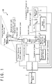
- Fig. 1 is a block diagram that shows a configuration of a laser irradiation apparatus 100 according to an embodiment.
- the laser irradiation apparatus 100 is configured to irradiate a transmission laser to a target 10.
- a high-power transmission laser may be irradiated to the target 10.
- a transmission laser modulated based on communication data may be irradiated to the target 10.
- the laser irradiation apparatus 100 is configured to appropriately correct a wavefront of the transmission laser based on a movement of the target 10. Specifically, the laser irradiation apparatus 100 predicts a predicted movement position that is a position into which the target 10 is predicted to move at a time t k in future and emits the search laser to the predicted movement position. The laser irradiation apparatus 100 acquires information of fluctuations of the atmosphere in an optical path between the laser irradiation apparatus 100 and the predicted movement position based on observation light that returns to the laser irradiation apparatus 100 when a search laser is emitted.
- the backscattered light can be used as observation light.
- reflected light can be used as observation light.
- the laser irradiation apparatus 100 emits the transmission laser of which the wavefront is corrected based on information of the atmospheric fluctuation included in observation light to the target 10 at the time t k . According to such operations, even if the target 10 is moving at high speed, the wavefront of the transmission laser can be appropriately corrected and a reliability of irradiating the transmission laser to the target 10 can be improved. Configurations and operations of the laser irradiation apparatus 100 will be described below in detail.
- the laser irradiation apparatus 100 is provided with a target observer 1, a meteorological meter 2, a transmission laser generator 3, an atmospheric fluctuation observer 4, irradiation optics 5 and a controller 6.
- the target observer 1 observes the target 10 that moves in the atmosphere and acquires observation information that indicates the movement of the target 10.
- the observation information may include, for example, a present position, a moving speed, a moving direction of the target 10.
- the target observer 1 may be provided with a radar, a camera, or the like.
- the meteorological meter 2 acquires meteorological information that indicates weather.
- the meteorological information may include information that indicates, for example, wind speed, wind direction, air temperature and humidity.
- the transmission laser generator 3 generates the transmission laser to irradiate the target 10 therewith.
- the transmission laser generator 3 is configured to be capable of generating a high-power transmission beam.
- the transmission laser generator 3 is provided with a transmission laser source 11 and wavefront correction optics 12.
- the transmission laser source 11 is provided with a laser oscillator and generates the transmission laser.
- the wavefront correction optics 12 corrects the wavefront of the transmission laser received from the transmission laser source 11.
- the wavefront correction optics 12 is configured to correct the wavefront of the transmission laser based on wavefront correction data received from the controller 6.
- the wavefront correction data are data that indicate how the wavefront of the transmission laser should be corrected.
- the wavefront correction optics 12 may be provided with, for example, variable shape mirror of which a shape of a reflective surface is variable. In this case, the shape of the reflective surface of the variable shape mirror is controlled based on the wavefront correction data.
- the transmission laser of which the wavefront is corrected by the wavefront correction optics 12 is supplied to the irradiation optics 5.
- the atmospheric fluctuation observer 4 is configured to generate the search laser used to observe the atmospheric fluctuation and observe atmospheric fluctuation based on observation light acquired from the atmosphere when the search laser is emitted from the irradiation optics 5.
- the atmospheric fluctuation observer 4 is provided with a search laser source 13, a half mirror 14 and a wavefront sensor 15.
- the search laser source 13 generates the search laser.
- the half mirror 14 reflects the generated search laser to supply it to the irradiation optics 5 and transmits the observation light received from the irradiation optics 5 to supply it to the wavefront sensor 15.
- the wavefront sensor 15 detects the wavefront of the observation light and generates a wavefront sensor output that indicates a state of the wavefront of the observation light.
- the irradiation optics 5 emits the transmission laser generated by the transmission laser generator 3 to the target 10.
- the irradiation optics 5 further emits the search laser generated by the atmospheric fluctuation observer 4 and emits the observation light, that is acquired from the atmosphere when the search laser is emitted, to the atmospheric fluctuation observer 4.
- the irradiation optics 5 is provided with a half mirror 16 and a lens barrel 17.
- the half mirror 16 is configured to pass the transmission laser incident from the transmission laser generator 3 to make it enter the lens barrel 17.
- the half mirror 16 reflects the search laser incident from the atmospheric fluctuation observer 4 to make it enter the lens barrel 17, and reflects the observation light emitted from the lens barrel 17 to supply it to the atmospheric fluctuation observer 4.
- the lens barrel 17 is configured to emit the transmission laser and the search laser to a desired direction and to be capable of receiving observation light from the desired direction.
- the controller 6 performs data processing necessary for irradiating the transmission laser to the target 10, and performs control of the entire laser irradiation apparatus 100.
- the controller 6 operates as follows. At first, the controller 6 calculates the predicted movement position of the target 10 at a time in future based on the observation information acquired by the target observer 1. In addition, the controller 6 controls the search laser source 13 and the irradiation optics 5 so as to emit the search laser to the predicted movement position. Furthermore, the controller 6 generates wavefront correction data that is to be supplied to the wavefront correction optics 12 based on the wavefront sensor output that the wavefront sensor 15 outputs based on the observation light.
- the wavefront correction data may be generated based on meteorological information acquired by the meteorological meter 2, in addition to the wavefront sensor output. Furthermore, the controller 6 controls the transmission laser source 11 and the irradiation optics 5 so as to emit the transmission laser in a desired direction.
- Fig. 2 is a flowchart that indicates a procedure of an operation of the laser irradiation apparatus 100.
- the controller 6 calculates a position into which a target 10 is predicted to move at a future time t k , that is, a predicted movement position at the time t k , based on observation information acquired by the target observer 1.
- the target observer 1 includes a radar
- the predicted movement position at the time t k may be calculated based on a present position, a moving speed and a moving direction of the target 10 that are acquired by the radar.
- the target observer 1 includes a camera
- a present position, a moving speed and a moving direction of the target 10 may be calculated from captured images that are acquired by the camera and the predicted movement position at the time t k may be calculated therefrom.
- a search laser is emitted to the predicted movement position.
- the search laser is generated by the search laser source 13 and furthermore, the lens barrel 17 is operated so that the search laser is emitted to the predicted movement position.
- observation light that returns to the lens barrel 17 while the search laser is emitted to the predicted movement position is received by the wavefront sensor 15.
- a wavefront sensor output based on a shape of the wavefront of the observation light is outputted by the wavefront sensor 15.
- the wavefront sensor output includes atmospheric fluctuation information.
- wavefront correction data to be used to correct the wavefront at the time t k is calculated based on the wavefront sensor output that is outputted by the wavefront sensor 15.
- the wavefront correction data based on the fluctuation of the atmosphere between the laser irradiation apparatus 100 and the predicted movement position can be calculated.
- the meteorological information acquired by the meteorological meter 2 may be referred to calculate the wavefront correction data.
- the meteorological information is acquired as information indicating a status of the atmosphere such as information indicating wind speed, wind direction, air temperature and humidity.
- a time change of the atmospheric fluctuation may be predicted by the controller 6 based on the acquired meteorological information and the wavefront correction data may be calculated based on this prediction.
- a step S05 at the time t k , the transmission laser is emitted to the target 10, while correcting the wavefront of the transmission laser based on the wavefront correction data calculated in the step S04.
- the time to start the irradiation of the transmission laser to the target 10 may be the time t k or may be before the time t k .
- the transmission laser is irradiated to the target 10 by tracking the target 10. In this case also, at least at the time t k , the wavefront of the transmission laser is corrected based on the wavefront correction data calculated in the step S04.
- Corrections of the wavefront of the transmission laser after the time t k , at times t k+1 , t k+2 , ..., are also performed, similarly.
- an emission of the search laser for a correction of the wavefront of the transmission laser at the time t k+1 may be carried out simultaneously to the emission of the transmission laser at the previous time t k .
- the transmission laser may be emitted at the time t k to the predicted movement position of the time t k
- the search laser may be emitted to the predicted movement position of the time t k+1 .
- the search laser can be emitted simultaneously to the emission of the transmission laser.
- the search laser may have a wavelength different from the wavelength of the transmission laser.
- the transmission laser and the search laser can be easily separated.
- the lens barrel 17 may be configured to be capable of emitting the search laser to a direction different from the transmission laser by use of a difference of wavelengths
- the half mirror 16 may be configured to selectively supply the observation light to the atmospheric fluctuation observer 4 by use of the difference of wavelengths.
- the laser irradiation apparatus 100 of the present embodiment has an advantage that the wavefront of the transmission laser related to a target 10 moving at high speed can be appropriately corrected. If a method according to a conventional adaptive optics is applied as it is, atmospheric fluctuation information will be acquired from reflected light generated by a reflection of the transmission laser on the target 10, and the wavefront of the transmission laser will be corrected based on this atmospheric fluctuation information. However, as in such a method a time rag from a time of acquiring the atmospheric fluctuation information to a time of actually carrying out the wavefront correction inevitably exists, an optical path in which the atmospheric fluctuation information is acquired and an optical path in which the transmission laser with the corrected wavefront is emitted will be different from each other due to the movement of the target 10.
- the laser irradiation apparatus 100 of the present embodiment can appropriately correct the wavefront of the transmission laser, even if the target 10 is moving at high speed, because the optical path in which the atmospheric fluctuation information is acquired and the optical path in which the transmission laser with the corrected wavefront is emitted can be matched to each other.
- the laser irradiation apparatus 100 of the present embodiment has an advantage that demands for response speed of each device included in the laser irradiation apparatus 100 can be relaxed.
- a time grace from an emission of the search laser and a reception of observation light to an actual correction of the transmission laser wavefront can be ensured. This means that demands for response speed of each device included in the laser irradiation apparatus 100, specifically the wavefront sensor 15, the controller 6 and the wavefront correction optics 12, can be relaxed.
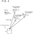
- a plurality of predicted movement positions may be calculated and atmospheric fluctuation information can be acquired for each of them.
- Fig. 3 indicates an example in which N predicted movement positions #1 to #N are calculated.
- N is an integer equal to or larger than 2.
- a search laser is emitted to each of the predicted movement positions #1 to #N
- wavefront correction data are calculated for each of the predicted movement positions #1 to #N based on observation light returned to the laser irradiation apparatus 100.
- wavefront correction data calculated for a predicted movement position #i are calculated based on observation light that returns when a search laser is emitted to the predicted movement position #i.
- i is an integer equal to or larger than 1 and equal to or less than N.
- the position of the target 10 at the time t k is specified based on observation information acquired by the target observer 1, and the wavefront correction data to be actually used for the correction of the wavefront is determined from the wavefront correction data calculated for each of the predicted movement positions #1 to #N based on the specified position of the target 10.
- a predicted movement position that is closest to the position of the target 10 at the time t k may be selected among the predicted movement positions #1 to #N, and the wavefront correction data calculated for this predicted movement position may be used for the correction of the wavefront at the time t k .
- a plurality of predicted movement positions that are close to the position of the target 10 at the time t k may be selected and the wavefront correction data to be actually used for the correction of the wavefront may be calculated from an interpolation of the wavefront correction data calculated for this plurality of predicted movement positions.
- the wavefront of the transmission laser can be appropriately corrected based on changes of movement direction or speed of the target 10.
- Fig. 4 is a block diagram that shows a configuration of a laser irradiation apparatus 100A according to another embodiment.
- no search laser source 13 and no half mirror 14 are provided, and a search laser and a transmission laser with a same wavelength are generated by time division by the transmission laser source 11.
- the laser irradiation apparatus 100A with the configuration in Fig. 4 also irradiates the transmission laser to the target 10 with a procedure similar to the procedure indicated in Fig. 2 , except that the search laser and the transmission laser are generated by time division.
- step S01 the predicted movement position at the time t k is calculated, and in the step S02, the search laser generated by the transmission laser source 11 is emitted to the predicted movement position.
- step S03 observation light that returns to the lens barrel 17 while the search laser is emitted to the predicted movement position is received by the wavefront sensor 15.
- step S04 wavefront correction data to be used for the correction of the wavefront at the time t k is calculated based on the wavefront sensor output that is outputted by the wavefront sensor 15.
- step S05 at the time t k , the transmission laser is emitted to the target 10 by correcting the wavefront of the transmission laser based on the wavefront correction data calculated in the step S04.
- the configuration of the laser irradiation apparatus 100A in Fig. 4 requires no light source dedicated to generation of the search laser, and the scale of the apparatus can be reduced.
- the configuration in Fig. 4 is useful for a use in which a continued irradiation of the transmission laser to the target 10 is not required, such as an optical communication.
Landscapes
- Engineering & Computer Science (AREA)
- Physics & Mathematics (AREA)
- Radar, Positioning & Navigation (AREA)
- Remote Sensing (AREA)
- General Engineering & Computer Science (AREA)
- General Physics & Mathematics (AREA)
- Electromagnetism (AREA)
- Computer Networks & Wireless Communication (AREA)
- Optics & Photonics (AREA)
- Lasers (AREA)
- Mechanical Light Control Or Optical Switches (AREA)
- Aiming, Guidance, Guns With A Light Source, Armor, Camouflage, And Targets (AREA)
- Optical Radar Systems And Details Thereof (AREA)
Abstract
Description
- The present invention relates to a laser irradiation apparatus and a laser irradiation method.
- When a laser irradiation apparatus irradiates a laser to a target that exists far away, the laser is affected by atmospheric fluctuations. For example, when a wavefront of the laser is disturbed by atmospheric fluctuations, an optical path of the laser may be bent or diffused.
- Correction of a wavefront of a laser is effective to reduce effects of atmospheric fluctuations (refer to Japanese Patent Publication No.
2011-185567 - https://www.subarutelescope.org/Introductio n/instrument/AO.html
- The target to which a laser is to be irradiated may move at high speed. It is desirable to reliably irradiate a target moving at high speed with a laser.
- [Patent Literature 1] Japanese Patent Publication No.
2011-185567 - https://www.subarutelescope.org/Introduction/ins trument/AO.html
- Therefore, an objective of the present invention is to provide techniques of reliably irradiating a target moving at high speed with a laser. Other objectives and new features of the present invention will be understood by skilled persons in the art from following disclosures.
- From an aspect of the present invention, a laser irradiation apparatus is provided with a controller that calculates at least one predicted movement position into which a target is predicted to move at a specific time in future, a transmission laser source that generates a transmission laser, irradiation optics configured to emit the transmission laser to the target and emit search laser to the predicted movement position and wavefront correction optics configured to correct a wavefront of the transmission laser at the specific time based on observation light that returns when the search laser is emitted to the predicted movement position.
- According to an embodiment, the laser irradiation apparatus may be further provided with a search laser source that generates the search laser and is provided separately from the transmission laser source. In such a configuration, the search laser generated by the search laser source can be emitted to the predicted movement position when the transmission laser generated by the transmission laser source is emitted to the target. In such an operation, it is preferable that the search laser has a wavelength different from the transmission laser.
- In an embodiment, the search laser that generates the observation light used for a correction of a wavefront of the transmission laser at the specific time is irradiated to the predicted movement position before the specific time.
- In an embodiment, a plurality of predicted movement positions is predicted. In this case, in an embodiment, the controller calculates wavefront correction data for each of the plurality of predicted movement positions based on observation light that returns when the search laser is emitted to each of the plurality of predicted movement positions, specifies a position of the target at the specific time based on observation information acquired by a target observer that observes the target and determines wavefront correction data to be actually used to correct the wavefront of the transmission laser at the specific time based on the specified position of the target and the wavefront correction data calculated for each of the plurality of predicted movement positions. In this case, the wavefront correction optics correct the wavefront of the transmission laser based on the determined wavefront correction data at the specific time.
- In an embodiment, the laser irradiation apparatus is further provided with a meteorological meter that acquires meteorological information that indicates weather. In this case, the wavefront of the transmission laser may be corrected based on the meteorological information.
- In another aspect of the present invention, a laser irradiation method includes calculating at least one predicted movement position into which a target is predicted to move at a specific time in future, emitting a search laser to the predicted movement position, emitting a transmission laser to the target and correcting a wavefront of the transmission laser at the specific time based on observation light that returns when the search laser is emitted to the predicted movement position.
- In an embodiment, the search laser is emitted to the predicted movement position when the transmission laser is emitted to the target.
- In an embodiment, a plurality of predicted movement positions is predicted. In this case, the correcting the wavefront of the transmission laser may include calculating wavefront correction data for each of the plurality of predicted movement position based on observation light that returns when the search laser is emitted to each of the plurality of predicted movement positions, observing the target and specifying a position of the target at the specific time, determining wavefront correction data to be actually used to correct the wavefront of the transmission laser at the specific time based on the specified position of the target and the wavefront correction data calculated for each of the plurality of predicted movement positions and correcting the wavefront of the transmission laser based on the determined wavefront correction data at the specific time.
- According to the present invention, techniques of reliably irradiating a target moving at high speed with a laser will be provided.
-
- [
Fig. 1] Fig. 1 is a block diagram that shows a configuration of a laser irradiation apparatus according to an embodiment. - [
Fig. 2] Fig. 2 is a flowchart that shows a procedure of an operation of a laser irradiation apparatus according to an embodiment. - [
Fig. 3] Fig. 3 is a diagram for explaining an operation of calculating a plurality of predicted movement positions. - [
Fig. 4] Fig. 4 is a block diagram that shows a configuration of a laser irradiation apparatus according to another embodiment. -
Fig. 1 is a block diagram that shows a configuration of alaser irradiation apparatus 100 according to an embodiment. Thelaser irradiation apparatus 100 is configured to irradiate a transmission laser to atarget 10. When thelaser irradiation apparatus 100 is used to destroy thetarget 10, a high-power transmission laser may be irradiated to thetarget 10. In addition, when thelaser irradiation apparatus 100 is used for an optical communication with thetarget 10, a transmission laser modulated based on communication data may be irradiated to thetarget 10. - The
laser irradiation apparatus 100 according to the present embodiment is configured to appropriately correct a wavefront of the transmission laser based on a movement of thetarget 10. Specifically, thelaser irradiation apparatus 100 predicts a predicted movement position that is a position into which thetarget 10 is predicted to move at a time tk in future and emits the search laser to the predicted movement position. Thelaser irradiation apparatus 100 acquires information of fluctuations of the atmosphere in an optical path between thelaser irradiation apparatus 100 and the predicted movement position based on observation light that returns to thelaser irradiation apparatus 100 when a search laser is emitted. As backscattered light is generated by light scattering in the atmosphere when a search laser is emitted to the predicted movement position, the backscattered light can be used as observation light. In addition, when a size of thetarget 10 is large enough and the search laser is reflected by thetarget 10, reflected light can be used as observation light. Thelaser irradiation apparatus 100 emits the transmission laser of which the wavefront is corrected based on information of the atmospheric fluctuation included in observation light to thetarget 10 at the time tk. According to such operations, even if thetarget 10 is moving at high speed, the wavefront of the transmission laser can be appropriately corrected and a reliability of irradiating the transmission laser to thetarget 10 can be improved. Configurations and operations of thelaser irradiation apparatus 100 will be described below in detail. - In the present embodiment, the
laser irradiation apparatus 100 is provided with atarget observer 1, ameteorological meter 2, atransmission laser generator 3, anatmospheric fluctuation observer 4,irradiation optics 5 and a controller 6. - The
target observer 1 observes thetarget 10 that moves in the atmosphere and acquires observation information that indicates the movement of thetarget 10. The observation information may include, for example, a present position, a moving speed, a moving direction of thetarget 10. Thetarget observer 1 may be provided with a radar, a camera, or the like. - The
meteorological meter 2 acquires meteorological information that indicates weather. The meteorological information may include information that indicates, for example, wind speed, wind direction, air temperature and humidity. - The
transmission laser generator 3 generates the transmission laser to irradiate thetarget 10 therewith. When a purpose of irradiating the transmission laser to thetarget 10 is to destroy thetarget 10, thetransmission laser generator 3 is configured to be capable of generating a high-power transmission beam. - In the present embodiment, the
transmission laser generator 3 is provided with a transmission laser source 11 andwavefront correction optics 12. The transmission laser source 11 is provided with a laser oscillator and generates the transmission laser. The wavefront correction optics 12 corrects the wavefront of the transmission laser received from the transmission laser source 11. Thewavefront correction optics 12 is configured to correct the wavefront of the transmission laser based on wavefront correction data received from the controller 6. Herein, the wavefront correction data are data that indicate how the wavefront of the transmission laser should be corrected. Thewavefront correction optics 12 may be provided with, for example, variable shape mirror of which a shape of a reflective surface is variable. In this case, the shape of the reflective surface of the variable shape mirror is controlled based on the wavefront correction data. The transmission laser of which the wavefront is corrected by thewavefront correction optics 12 is supplied to theirradiation optics 5. - The
atmospheric fluctuation observer 4 is configured to generate the search laser used to observe the atmospheric fluctuation and observe atmospheric fluctuation based on observation light acquired from the atmosphere when the search laser is emitted from theirradiation optics 5. In the present embodiment, theatmospheric fluctuation observer 4 is provided with asearch laser source 13, ahalf mirror 14 and awavefront sensor 15. Thesearch laser source 13 generates the search laser. Thehalf mirror 14 reflects the generated search laser to supply it to theirradiation optics 5 and transmits the observation light received from theirradiation optics 5 to supply it to thewavefront sensor 15. Thewavefront sensor 15 detects the wavefront of the observation light and generates a wavefront sensor output that indicates a state of the wavefront of the observation light. - The
irradiation optics 5 emits the transmission laser generated by thetransmission laser generator 3 to thetarget 10. Theirradiation optics 5 further emits the search laser generated by theatmospheric fluctuation observer 4 and emits the observation light, that is acquired from the atmosphere when the search laser is emitted, to theatmospheric fluctuation observer 4. - In the present embodiment, the
irradiation optics 5 is provided with ahalf mirror 16 and alens barrel 17. Thehalf mirror 16 is configured to pass the transmission laser incident from thetransmission laser generator 3 to make it enter thelens barrel 17. In addition, thehalf mirror 16 reflects the search laser incident from theatmospheric fluctuation observer 4 to make it enter thelens barrel 17, and reflects the observation light emitted from thelens barrel 17 to supply it to theatmospheric fluctuation observer 4. Thelens barrel 17 is configured to emit the transmission laser and the search laser to a desired direction and to be capable of receiving observation light from the desired direction. - The controller 6 performs data processing necessary for irradiating the transmission laser to the
target 10, and performs control of the entirelaser irradiation apparatus 100. In an embodiment, the controller 6 operates as follows. At first, the controller 6 calculates the predicted movement position of thetarget 10 at a time in future based on the observation information acquired by thetarget observer 1. In addition, the controller 6 controls thesearch laser source 13 and theirradiation optics 5 so as to emit the search laser to the predicted movement position. Furthermore, the controller 6 generates wavefront correction data that is to be supplied to thewavefront correction optics 12 based on the wavefront sensor output that thewavefront sensor 15 outputs based on the observation light. The wavefront correction data may be generated based on meteorological information acquired by themeteorological meter 2, in addition to the wavefront sensor output. Furthermore, the controller 6 controls the transmission laser source 11 and theirradiation optics 5 so as to emit the transmission laser in a desired direction. -
Fig. 2 is a flowchart that indicates a procedure of an operation of thelaser irradiation apparatus 100. - In a step S01, the controller 6 calculates a position into which a
target 10 is predicted to move at a future time tk, that is, a predicted movement position at the time tk, based on observation information acquired by thetarget observer 1. When thetarget observer 1 includes a radar, the predicted movement position at the time tk may be calculated based on a present position, a moving speed and a moving direction of thetarget 10 that are acquired by the radar. In addition, when thetarget observer 1 includes a camera, a present position, a moving speed and a moving direction of thetarget 10 may be calculated from captured images that are acquired by the camera and the predicted movement position at the time tk may be calculated therefrom. - Then, in a step S02, a search laser is emitted to the predicted movement position. Under a control of the controller 6, the search laser is generated by the
search laser source 13 and furthermore, thelens barrel 17 is operated so that the search laser is emitted to the predicted movement position. - In a step S03, observation light that returns to the
lens barrel 17 while the search laser is emitted to the predicted movement position is received by thewavefront sensor 15. A wavefront sensor output based on a shape of the wavefront of the observation light is outputted by thewavefront sensor 15. As the wavefront of the observation light includes information of fluctuation of atmosphere between thelaser irradiation apparatus 100 and the predicted movement position, the wavefront sensor output includes atmospheric fluctuation information. - In a step S04, wavefront correction data to be used to correct the wavefront at the time tk is calculated based on the wavefront sensor output that is outputted by the
wavefront sensor 15. By referring the wavefront sensor output, the wavefront correction data based on the fluctuation of the atmosphere between thelaser irradiation apparatus 100 and the predicted movement position can be calculated. The meteorological information acquired by themeteorological meter 2 may be referred to calculate the wavefront correction data. In an embodiment, the meteorological information is acquired as information indicating a status of the atmosphere such as information indicating wind speed, wind direction, air temperature and humidity. A time change of the atmospheric fluctuation may be predicted by the controller 6 based on the acquired meteorological information and the wavefront correction data may be calculated based on this prediction. By calculating the wavefront correction data based on meteorological information, an accuracy of the wavefront correction can be improved. - In a step S05, at the time tk, the transmission laser is emitted to the
target 10, while correcting the wavefront of the transmission laser based on the wavefront correction data calculated in the step S04. The time to start the irradiation of the transmission laser to thetarget 10 may be the time tk or may be before the time tk. When the time to start the irradiation of the transmission laser to thetarget 10 is before the time tk, the transmission laser is irradiated to thetarget 10 by tracking thetarget 10. In this case also, at least at the time tk, the wavefront of the transmission laser is corrected based on the wavefront correction data calculated in the step S04. - Corrections of the wavefront of the transmission laser after the time tk, at times tk+1, tk+2, ..., are also performed, similarly. Herein, an emission of the search laser for a correction of the wavefront of the transmission laser at the time tk+1 may be carried out simultaneously to the emission of the transmission laser at the previous time tk. Specifically, the transmission laser may be emitted at the time tk to the predicted movement position of the time tk, and the search laser may be emitted to the predicted movement position of the time tk+1. In the present embodiment, as the transmission laser and the search laser are separately generated by the transmission laser source 11 and the
search laser source 13, respectively, the search laser can be emitted simultaneously to the emission of the transmission laser. - In an embodiment, the search laser may have a wavelength different from the wavelength of the transmission laser. As the search laser has a wavelength different from the wavelength of the transmission laser, the transmission laser and the search laser can be easily separated. For example, the
lens barrel 17 may be configured to be capable of emitting the search laser to a direction different from the transmission laser by use of a difference of wavelengths, and thehalf mirror 16 may be configured to selectively supply the observation light to theatmospheric fluctuation observer 4 by use of the difference of wavelengths. - The
laser irradiation apparatus 100 of the present embodiment has an advantage that the wavefront of the transmission laser related to atarget 10 moving at high speed can be appropriately corrected. If a method according to a conventional adaptive optics is applied as it is, atmospheric fluctuation information will be acquired from reflected light generated by a reflection of the transmission laser on thetarget 10, and the wavefront of the transmission laser will be corrected based on this atmospheric fluctuation information. However, as in such a method a time rag from a time of acquiring the atmospheric fluctuation information to a time of actually carrying out the wavefront correction inevitably exists, an optical path in which the atmospheric fluctuation information is acquired and an optical path in which the transmission laser with the corrected wavefront is emitted will be different from each other due to the movement of thetarget 10. This decreases wavefront correction accuracy. On the other hand, thelaser irradiation apparatus 100 of the present embodiment can appropriately correct the wavefront of the transmission laser, even if thetarget 10 is moving at high speed, because the optical path in which the atmospheric fluctuation information is acquired and the optical path in which the transmission laser with the corrected wavefront is emitted can be matched to each other. - In addition, the
laser irradiation apparatus 100 of the present embodiment has an advantage that demands for response speed of each device included in thelaser irradiation apparatus 100 can be relaxed. In an operation of thelaser irradiation apparatus 100 of the present embodiment, a time grace from an emission of the search laser and a reception of observation light to an actual correction of the transmission laser wavefront can be ensured. This means that demands for response speed of each device included in thelaser irradiation apparatus 100, specifically thewavefront sensor 15, the controller 6 and thewavefront correction optics 12, can be relaxed. - As illustrated in
Fig. 3 , in the step S01, a plurality of predicted movement positions may be calculated and atmospheric fluctuation information can be acquired for each of them.Fig. 3 indicates an example in which N predictedmovement positions # 1 to #N are calculated. Herein, N is an integer equal to or larger than 2. - In this case, in the step S02, a search laser is emitted to each of the predicted
movement positions # 1 to #N, and furthermore, in the step S04, wavefront correction data are calculated for each of the predictedmovement positions # 1 to #N based on observation light returned to thelaser irradiation apparatus 100. Herein, wavefront correction data calculated for a predicted movement position #i are calculated based on observation light that returns when a search laser is emitted to the predicted movement position #i. Herein, i is an integer equal to or larger than 1 and equal to or less than N. - In the step S05, the position of the
target 10 at the time tk is specified based on observation information acquired by thetarget observer 1, and the wavefront correction data to be actually used for the correction of the wavefront is determined from the wavefront correction data calculated for each of the predictedmovement positions # 1 to #N based on the specified position of thetarget 10. In an embodiment, a predicted movement position that is closest to the position of thetarget 10 at the time tk may be selected among the predictedmovement positions # 1 to #N, and the wavefront correction data calculated for this predicted movement position may be used for the correction of the wavefront at the time tk. In another embodiment, a plurality of predicted movement positions that are close to the position of thetarget 10 at the time tk may be selected and the wavefront correction data to be actually used for the correction of the wavefront may be calculated from an interpolation of the wavefront correction data calculated for this plurality of predicted movement positions. - By calculating the wavefront correction data in this way, the wavefront of the transmission laser can be appropriately corrected based on changes of movement direction or speed of the
target 10. -
Fig. 4 is a block diagram that shows a configuration of alaser irradiation apparatus 100A according to another embodiment. In the present embodiment, nosearch laser source 13 and nohalf mirror 14 are provided, and a search laser and a transmission laser with a same wavelength are generated by time division by the transmission laser source 11. - The
laser irradiation apparatus 100A with the configuration inFig. 4 also irradiates the transmission laser to thetarget 10 with a procedure similar to the procedure indicated inFig. 2 , except that the search laser and the transmission laser are generated by time division. - In the step S01, the predicted movement position at the time tk is calculated, and in the step S02, the search laser generated by the transmission laser source 11 is emitted to the predicted movement position. In the step S03, observation light that returns to the
lens barrel 17 while the search laser is emitted to the predicted movement position is received by thewavefront sensor 15. - In the step S04, wavefront correction data to be used for the correction of the wavefront at the time tk is calculated based on the wavefront sensor output that is outputted by the
wavefront sensor 15. In the step S05, at the time tk, the transmission laser is emitted to thetarget 10 by correcting the wavefront of the transmission laser based on the wavefront correction data calculated in the step S04. - The configuration of the
laser irradiation apparatus 100A inFig. 4 requires no light source dedicated to generation of the search laser, and the scale of the apparatus can be reduced. The configuration inFig. 4 is useful for a use in which a continued irradiation of the transmission laser to thetarget 10 is not required, such as an optical communication. - Although the embodiments of the present invention are disclosed above in detail, the present invention is not limited to the above described embodiments. It would be understood by skilled persons in the art that the present invention can be implemented with various modifications. In addition, it should be noted that the embodiments disclosed in the present description can be implemented as a combination as long as there is no technical contradiction.
- It should be noted that this application claims priority based on the Japanese Patent Application No.
2018-138536 filed on July 24, 2018
Claims (10)
- A laser irradiation apparatus comprising:a controller configured to calculate at least one predicted movement position into which a target is predicted to move at a specific time in future;a transmission laser source configured to generate a transmission laser;irradiation optics configured to emit the transmission laser to the target and emit a search laser to the predicted movement position; andwavefront correction optics configured to correct a wavefront of the transmission laser at the specific time based on observation light that returns when the search laser is emitted to the predicted movement position.
- The laser irradiation apparatus according to claim 1, further comprising a search laser source configured to generate the search laser and provided separately from the transmission laser source.
- The laser irradiation apparatus according to claim 2,
wherein the search laser has a wavelength different from the transmission laser. - The laser irradiation apparatus according to claim 2 or 3,
wherein the search laser generated by the search laser source is emitted to the predicted movement position when the transmission laser generated by the transmission laser source is emitted to the target. - The laser irradiation apparatus according to any one of claims 1 to 4,
wherein the search laser, that is configured to generate the observation light used for a correction of a wavefront of the transmission laser at the specific time, is irradiated to the predicted movement position before the specific time. - The laser irradiation apparatus according to any one of claims 1 to 5,
further comprising a target observer configured to observe the target and acquire observation information,
wherein the at least one predicted movement position includes a plurality of predicted movement positions,
wherein the controller is configured to:calculate wavefront correction data for each of the plurality of predicted movement positions based on observation light that returns when the search laser is emitted to each of the plurality of predicted movement positions,specify a position of the target at the specific time based on the observation information; anddetermine wavefront correction data to be actually used to correct the wavefront of the transmission laser at the specific time based on the specified position of the target and the wavefront correction data calculated for each of the plurality of predicted movement positions, andwherein the wavefront correction optics are configured to correct the wavefront of the transmission laser based on the determined wavefront correction data at the specific time. - The laser irradiation apparatus according to any one of claims 1 to 6,
further comprising a meteorological meter configured to acquire meteorological information that indicates weather,
wherein the wavefront of the transmission laser is corrected based on the meteorological information. - A laser irradiation method including:calculating at least one predicted movement position into which a target is predicted to move at a specific time in future;emitting a search laser to the predicted movement position;emitting a transmission laser to the target; andcorrecting a wavefront of the transmission laser at the specific time based on observation light that returns when the search laser is emitted to the predicted movement position.
- The laser irradiation method according to claim 8,
wherein the search laser is emitted to the predicted movement position when the transmission laser is emitted to the target. - The laser irradiation method according to claim 8 or 9,
wherein the at least one predicted movement position includes a plurality of predicted movement positions, and
wherein the correcting the wavefront of the transmission laser includes:calculating wavefront correction data for each of the plurality of predicted movement position based on observation light that returns when the search laser is emitted to each of the plurality of predicted movement positions;observing the target and specifying a position of the target at the specific time;determining wavefront correction data to be actually used to correct the wavefront of the transmission laser at the specific time based on the specified position of the target and the wavefront correction data calculated for each of the plurality of predicted movement positions; andcorrecting the wavefront of the transmission laser based on the determined wavefront correction data at the specific time.
Applications Claiming Priority (2)
| Application Number | Priority Date | Filing Date | Title |
|---|---|---|---|
| JP2018138536A JP7174934B2 (en) | 2018-07-24 | 2018-07-24 | Laser beam irradiation device and laser beam irradiation method |
| PCT/JP2019/026481 WO2020022012A1 (en) | 2018-07-24 | 2019-07-03 | Laser beam irradiation device and laser beam irradiation method |
Publications (3)
| Publication Number | Publication Date |
|---|---|
| EP3809092A1 true EP3809092A1 (en) | 2021-04-21 |
| EP3809092A4 EP3809092A4 (en) | 2021-08-11 |
| EP3809092B1 EP3809092B1 (en) | 2024-08-21 |
Family
ID=69181683
Family Applications (1)
| Application Number | Title | Priority Date | Filing Date |
|---|---|---|---|
| EP19841840.2A Active EP3809092B1 (en) | 2018-07-24 | 2019-07-03 | Laser beam irradiation device and laser beam irradiation method |
Country Status (4)
| Country | Link |
|---|---|
| US (1) | US12379187B2 (en) |
| EP (1) | EP3809092B1 (en) |
| JP (1) | JP7174934B2 (en) |
| WO (1) | WO2020022012A1 (en) |
Families Citing this family (4)
| Publication number | Priority date | Publication date | Assignee | Title |
|---|---|---|---|---|
| US12270630B2 (en) | 2019-11-03 | 2025-04-08 | Lasermotive, Inc | Dual-use power beaming system |
| US11581953B2 (en) * | 2019-11-03 | 2023-02-14 | Lasermotive, Inc. | Dual-use power beaming system |
| JP7500743B2 (en) * | 2020-02-17 | 2024-06-17 | ビ-エイイ- システムズ パブリック リミテッド カンパニ- | Laser Controller |
| JP7566621B2 (en) * | 2020-12-24 | 2024-10-15 | 三菱重工業株式会社 | Laser Tracking Device |
Family Cites Families (10)
| Publication number | Priority date | Publication date | Assignee | Title |
|---|---|---|---|---|
| US6396577B1 (en) * | 2001-03-19 | 2002-05-28 | Thomas P. Ramstack | Lidar-based air defense system |
| US7002127B2 (en) * | 2002-07-19 | 2006-02-21 | Lockheed Corp | Method and system for wavefront compensation |
| EP2167988A4 (en) | 2007-06-14 | 2012-01-25 | Raytheon Co | Methods and apparatus for countering a projectile |
| US8218589B1 (en) * | 2008-07-28 | 2012-07-10 | The United States Of America As Represented By The Secretary Of The Air Force | High-energy laser atmospheric compensation and aimpoint maintenance |
| JP2011185567A (en) | 2010-03-10 | 2011-09-22 | Mitsubishi Electric Corp | High output laser irradiation device |
| JP2016042550A (en) * | 2014-08-19 | 2016-03-31 | 株式会社東芝 | Laser irradiation apparatus and laser irradiation method |
| JP2017157737A (en) * | 2016-03-03 | 2017-09-07 | 株式会社東芝 | Laser irradiation system and reflection optical device |
| CN107765711A (en) * | 2016-08-18 | 2018-03-06 | 邹科颖 | A kind of laser tracking system debugging apparatus |
| CN206354251U (en) * | 2016-12-16 | 2017-07-28 | 东莞市万科建筑技术研究有限公司 | Laser Mosquito Killer |
| EP3339387B1 (en) | 2016-12-22 | 2020-06-24 | Evonik Operations GmbH | Compounds based on of adducts with isocyanates for coating compositions |
-
2018
- 2018-07-24 JP JP2018138536A patent/JP7174934B2/en active Active
-
2019
- 2019-07-03 WO PCT/JP2019/026481 patent/WO2020022012A1/en not_active Ceased
- 2019-07-03 US US17/258,817 patent/US12379187B2/en active Active
- 2019-07-03 EP EP19841840.2A patent/EP3809092B1/en active Active
Also Published As
| Publication number | Publication date |
|---|---|
| US12379187B2 (en) | 2025-08-05 |
| EP3809092B1 (en) | 2024-08-21 |
| JP7174934B2 (en) | 2022-11-18 |
| JP2020016370A (en) | 2020-01-30 |
| EP3809092A4 (en) | 2021-08-11 |
| WO2020022012A1 (en) | 2020-01-30 |
| US20210270568A1 (en) | 2021-09-02 |
Similar Documents
| Publication | Publication Date | Title |
|---|---|---|
| EP3809092B1 (en) | Laser beam irradiation device and laser beam irradiation method | |
| US9897697B2 (en) | Distance measuring method using dynamic pulse width adaptation | |
| EP2884306B1 (en) | Radar device | |
| EP3248025B1 (en) | Optical phased array focus control for active illuminated swir range selection | |
| US11408982B2 (en) | Electromagnetic wave detection apparatus, program, and electromagnetic wave detection system | |
| US10310086B2 (en) | Method and device for local stabilization of a radiation spot on a remote target object | |
| JPWO2019202676A1 (en) | Laser radar device | |
| WO2017175297A1 (en) | Laser radar device | |
| EP3588131B1 (en) | Electromagnetic wave detection device, program, and electromagnetic wave detection system | |
| JP7208598B2 (en) | Adaptive optics system and optical compensation method | |
| US20200033116A1 (en) | Electromagnetic wave detection apparatus, program, and electromagnetic wave detection system | |
| WO2022219911A1 (en) | Device and method for measuring distance and/or speed of object | |
| US11513191B2 (en) | System and method for predictive compensation of uplink laser beam atmospheric jitter for high energy laser weapon systems | |
| JP5616025B2 (en) | Lightwave distance measuring method and lightwave distance measuring apparatus | |
| US9726462B2 (en) | Method and device for local stabilization of a radiation spot on a remote target object | |
| KR102103828B1 (en) | Method for driving identification of friend or foe apparatus for personal combat system | |
| US20250374911A1 (en) | Mobile removal device | |
| US11953598B2 (en) | Laser tracking device | |
| JP6652816B2 (en) | Space object observation system and space object observation method | |
| KR102103826B1 (en) | Method for driving identification of friend or foe apparatus for personal combat system | |
| KR102103825B1 (en) | Identification of friend or foe apparatus for personal combat system | |
| CN111670521B (en) | Method for emitting laser light | |
| CN114514409B (en) | Optical distance measuring device and processing device | |
| KR102103827B1 (en) | Identification of friend or foe apparatus for personal combat system | |
| JP2017101894A (en) | Laser protection system and laser protection method |
Legal Events
| Date | Code | Title | Description |
|---|---|---|---|
| STAA | Information on the status of an ep patent application or granted ep patent |
Free format text: STATUS: THE INTERNATIONAL PUBLICATION HAS BEEN MADE |
|
| PUAI | Public reference made under article 153(3) epc to a published international application that has entered the european phase |
Free format text: ORIGINAL CODE: 0009012 |
|
| STAA | Information on the status of an ep patent application or granted ep patent |
Free format text: STATUS: REQUEST FOR EXAMINATION WAS MADE |
|
| 17P | Request for examination filed |
Effective date: 20210113 |
|
| AK | Designated contracting states |
Kind code of ref document: A1 Designated state(s): AL AT BE BG CH CY CZ DE DK EE ES FI FR GB GR HR HU IE IS IT LI LT LU LV MC MK MT NL NO PL PT RO RS SE SI SK SM TR |
|
| AX | Request for extension of the european patent |
Extension state: BA ME |
|
| A4 | Supplementary search report drawn up and despatched |
Effective date: 20210714 |
|
| RIC1 | Information provided on ipc code assigned before grant |
Ipc: F41H 13/00 20060101AFI20210708BHEP Ipc: G01W 1/00 20060101ALI20210708BHEP Ipc: H01S 3/00 20060101ALI20210708BHEP Ipc: G02B 26/06 20060101ALI20210708BHEP Ipc: G01S 17/86 20200101ALI20210708BHEP Ipc: G01S 17/95 20060101ALI20210708BHEP Ipc: G01S 13/58 20060101ALI20210708BHEP Ipc: G01S 13/72 20060101ALI20210708BHEP Ipc: F41G 3/08 20060101ALI20210708BHEP Ipc: F41G 3/14 20060101ALI20210708BHEP Ipc: G01S 13/86 20060101ALI20210708BHEP |
|
| DAV | Request for validation of the european patent (deleted) | ||
| DAX | Request for extension of the european patent (deleted) | ||
| REG | Reference to a national code |
Ref country code: DE Ref legal event code: R079 Free format text: PREVIOUS MAIN CLASS: F41G0003260000 Ipc: F41H0013000000 Ref country code: DE Ref legal event code: R079 Ref document number: 602019057577 Country of ref document: DE Free format text: PREVIOUS MAIN CLASS: F41G0003260000 Ipc: F41H0013000000 |
|
| GRAP | Despatch of communication of intention to grant a patent |
Free format text: ORIGINAL CODE: EPIDOSNIGR1 |
|
| STAA | Information on the status of an ep patent application or granted ep patent |
Free format text: STATUS: GRANT OF PATENT IS INTENDED |
|
| RIC1 | Information provided on ipc code assigned before grant |
Ipc: G01S 17/66 20060101ALI20240212BHEP Ipc: G01W 1/00 20060101ALI20240212BHEP Ipc: H01S 3/00 20060101ALI20240212BHEP Ipc: G02B 26/06 20060101ALI20240212BHEP Ipc: G01S 17/86 20200101ALI20240212BHEP Ipc: G01S 17/95 20060101ALI20240212BHEP Ipc: G01S 13/58 20060101ALI20240212BHEP Ipc: G01S 13/72 20060101ALI20240212BHEP Ipc: F41G 3/08 20060101ALI20240212BHEP Ipc: F41G 3/14 20060101ALI20240212BHEP Ipc: G01S 13/86 20060101ALI20240212BHEP Ipc: F41H 13/00 20060101AFI20240212BHEP |
|
| INTG | Intention to grant announced |
Effective date: 20240318 |
|
| GRAS | Grant fee paid |
Free format text: ORIGINAL CODE: EPIDOSNIGR3 |
|
| GRAA | (expected) grant |
Free format text: ORIGINAL CODE: 0009210 |
|
| STAA | Information on the status of an ep patent application or granted ep patent |
Free format text: STATUS: THE PATENT HAS BEEN GRANTED |
|
| AK | Designated contracting states |
Kind code of ref document: B1 Designated state(s): AL AT BE BG CH CY CZ DE DK EE ES FI FR GB GR HR HU IE IS IT LI LT LU LV MC MK MT NL NO PL PT RO RS SE SI SK SM TR |
|
| REG | Reference to a national code |
Ref country code: GB Ref legal event code: FG4D |
|
| REG | Reference to a national code |
Ref country code: CH Ref legal event code: EP |
|
| REG | Reference to a national code |
Ref country code: IE Ref legal event code: FG4D |
|
| REG | Reference to a national code |
Ref country code: DE Ref legal event code: R096 Ref document number: 602019057577 Country of ref document: DE |
|
| REG | Reference to a national code |
Ref country code: LT Ref legal event code: MG9D |
|
| REG | Reference to a national code |
Ref country code: NL Ref legal event code: MP Effective date: 20240821 |
|
| PG25 | Lapsed in a contracting state [announced via postgrant information from national office to epo] |
Ref country code: NO Free format text: LAPSE BECAUSE OF FAILURE TO SUBMIT A TRANSLATION OF THE DESCRIPTION OR TO PAY THE FEE WITHIN THE PRESCRIBED TIME-LIMIT Effective date: 20241121 |
|
| REG | Reference to a national code |
Ref country code: AT Ref legal event code: MK05 Ref document number: 1715872 Country of ref document: AT Kind code of ref document: T Effective date: 20240821 |
|
| PG25 | Lapsed in a contracting state [announced via postgrant information from national office to epo] |
Ref country code: NL Free format text: LAPSE BECAUSE OF FAILURE TO SUBMIT A TRANSLATION OF THE DESCRIPTION OR TO PAY THE FEE WITHIN THE PRESCRIBED TIME-LIMIT Effective date: 20240821 Ref country code: PT Free format text: LAPSE BECAUSE OF FAILURE TO SUBMIT A TRANSLATION OF THE DESCRIPTION OR TO PAY THE FEE WITHIN THE PRESCRIBED TIME-LIMIT Effective date: 20241223 Ref country code: FI Free format text: LAPSE BECAUSE OF FAILURE TO SUBMIT A TRANSLATION OF THE DESCRIPTION OR TO PAY THE FEE WITHIN THE PRESCRIBED TIME-LIMIT Effective date: 20240821 Ref country code: PL Free format text: LAPSE BECAUSE OF FAILURE TO SUBMIT A TRANSLATION OF THE DESCRIPTION OR TO PAY THE FEE WITHIN THE PRESCRIBED TIME-LIMIT Effective date: 20240821 Ref country code: GR Free format text: LAPSE BECAUSE OF FAILURE TO SUBMIT A TRANSLATION OF THE DESCRIPTION OR TO PAY THE FEE WITHIN THE PRESCRIBED TIME-LIMIT Effective date: 20241122 |
|
| PG25 | Lapsed in a contracting state [announced via postgrant information from national office to epo] |
Ref country code: BG Free format text: LAPSE BECAUSE OF FAILURE TO SUBMIT A TRANSLATION OF THE DESCRIPTION OR TO PAY THE FEE WITHIN THE PRESCRIBED TIME-LIMIT Effective date: 20240821 |
|
| PG25 | Lapsed in a contracting state [announced via postgrant information from national office to epo] |
Ref country code: LV Free format text: LAPSE BECAUSE OF FAILURE TO SUBMIT A TRANSLATION OF THE DESCRIPTION OR TO PAY THE FEE WITHIN THE PRESCRIBED TIME-LIMIT Effective date: 20240821 |
|
| PG25 | Lapsed in a contracting state [announced via postgrant information from national office to epo] |
Ref country code: AT Free format text: LAPSE BECAUSE OF FAILURE TO SUBMIT A TRANSLATION OF THE DESCRIPTION OR TO PAY THE FEE WITHIN THE PRESCRIBED TIME-LIMIT Effective date: 20240821 Ref country code: IS Free format text: LAPSE BECAUSE OF FAILURE TO SUBMIT A TRANSLATION OF THE DESCRIPTION OR TO PAY THE FEE WITHIN THE PRESCRIBED TIME-LIMIT Effective date: 20241221 |
|
| PG25 | Lapsed in a contracting state [announced via postgrant information from national office to epo] |
Ref country code: HR Free format text: LAPSE BECAUSE OF FAILURE TO SUBMIT A TRANSLATION OF THE DESCRIPTION OR TO PAY THE FEE WITHIN THE PRESCRIBED TIME-LIMIT Effective date: 20240821 |
|
| PG25 | Lapsed in a contracting state [announced via postgrant information from national office to epo] |
Ref country code: RS Free format text: LAPSE BECAUSE OF FAILURE TO SUBMIT A TRANSLATION OF THE DESCRIPTION OR TO PAY THE FEE WITHIN THE PRESCRIBED TIME-LIMIT Effective date: 20241121 Ref country code: ES Free format text: LAPSE BECAUSE OF FAILURE TO SUBMIT A TRANSLATION OF THE DESCRIPTION OR TO PAY THE FEE WITHIN THE PRESCRIBED TIME-LIMIT Effective date: 20240821 |
|
| PG25 | Lapsed in a contracting state [announced via postgrant information from national office to epo] |
Ref country code: RS Free format text: LAPSE BECAUSE OF FAILURE TO SUBMIT A TRANSLATION OF THE DESCRIPTION OR TO PAY THE FEE WITHIN THE PRESCRIBED TIME-LIMIT Effective date: 20241121 Ref country code: PT Free format text: LAPSE BECAUSE OF FAILURE TO SUBMIT A TRANSLATION OF THE DESCRIPTION OR TO PAY THE FEE WITHIN THE PRESCRIBED TIME-LIMIT Effective date: 20241223 Ref country code: PL Free format text: LAPSE BECAUSE OF FAILURE TO SUBMIT A TRANSLATION OF THE DESCRIPTION OR TO PAY THE FEE WITHIN THE PRESCRIBED TIME-LIMIT Effective date: 20240821 Ref country code: NO Free format text: LAPSE BECAUSE OF FAILURE TO SUBMIT A TRANSLATION OF THE DESCRIPTION OR TO PAY THE FEE WITHIN THE PRESCRIBED TIME-LIMIT Effective date: 20241121 Ref country code: NL Free format text: LAPSE BECAUSE OF FAILURE TO SUBMIT A TRANSLATION OF THE DESCRIPTION OR TO PAY THE FEE WITHIN THE PRESCRIBED TIME-LIMIT Effective date: 20240821 Ref country code: LV Free format text: LAPSE BECAUSE OF FAILURE TO SUBMIT A TRANSLATION OF THE DESCRIPTION OR TO PAY THE FEE WITHIN THE PRESCRIBED TIME-LIMIT Effective date: 20240821 Ref country code: IS Free format text: LAPSE BECAUSE OF FAILURE TO SUBMIT A TRANSLATION OF THE DESCRIPTION OR TO PAY THE FEE WITHIN THE PRESCRIBED TIME-LIMIT Effective date: 20241221 Ref country code: HR Free format text: LAPSE BECAUSE OF FAILURE TO SUBMIT A TRANSLATION OF THE DESCRIPTION OR TO PAY THE FEE WITHIN THE PRESCRIBED TIME-LIMIT Effective date: 20240821 Ref country code: GR Free format text: LAPSE BECAUSE OF FAILURE TO SUBMIT A TRANSLATION OF THE DESCRIPTION OR TO PAY THE FEE WITHIN THE PRESCRIBED TIME-LIMIT Effective date: 20241122 Ref country code: FI Free format text: LAPSE BECAUSE OF FAILURE TO SUBMIT A TRANSLATION OF THE DESCRIPTION OR TO PAY THE FEE WITHIN THE PRESCRIBED TIME-LIMIT Effective date: 20240821 Ref country code: ES Free format text: LAPSE BECAUSE OF FAILURE TO SUBMIT A TRANSLATION OF THE DESCRIPTION OR TO PAY THE FEE WITHIN THE PRESCRIBED TIME-LIMIT Effective date: 20240821 Ref country code: BG Free format text: LAPSE BECAUSE OF FAILURE TO SUBMIT A TRANSLATION OF THE DESCRIPTION OR TO PAY THE FEE WITHIN THE PRESCRIBED TIME-LIMIT Effective date: 20240821 Ref country code: AT Free format text: LAPSE BECAUSE OF FAILURE TO SUBMIT A TRANSLATION OF THE DESCRIPTION OR TO PAY THE FEE WITHIN THE PRESCRIBED TIME-LIMIT Effective date: 20240821 |
|
| PG25 | Lapsed in a contracting state [announced via postgrant information from national office to epo] |
Ref country code: DK Free format text: LAPSE BECAUSE OF FAILURE TO SUBMIT A TRANSLATION OF THE DESCRIPTION OR TO PAY THE FEE WITHIN THE PRESCRIBED TIME-LIMIT Effective date: 20240821 Ref country code: RO Free format text: LAPSE BECAUSE OF FAILURE TO SUBMIT A TRANSLATION OF THE DESCRIPTION OR TO PAY THE FEE WITHIN THE PRESCRIBED TIME-LIMIT Effective date: 20240821 Ref country code: SM Free format text: LAPSE BECAUSE OF FAILURE TO SUBMIT A TRANSLATION OF THE DESCRIPTION OR TO PAY THE FEE WITHIN THE PRESCRIBED TIME-LIMIT Effective date: 20240821 |
|
| PG25 | Lapsed in a contracting state [announced via postgrant information from national office to epo] |
Ref country code: EE Free format text: LAPSE BECAUSE OF FAILURE TO SUBMIT A TRANSLATION OF THE DESCRIPTION OR TO PAY THE FEE WITHIN THE PRESCRIBED TIME-LIMIT Effective date: 20240821 |
|
| PG25 | Lapsed in a contracting state [announced via postgrant information from national office to epo] |
Ref country code: CZ Free format text: LAPSE BECAUSE OF FAILURE TO SUBMIT A TRANSLATION OF THE DESCRIPTION OR TO PAY THE FEE WITHIN THE PRESCRIBED TIME-LIMIT Effective date: 20240821 |
|
| PG25 | Lapsed in a contracting state [announced via postgrant information from national office to epo] |
Ref country code: SK Free format text: LAPSE BECAUSE OF FAILURE TO SUBMIT A TRANSLATION OF THE DESCRIPTION OR TO PAY THE FEE WITHIN THE PRESCRIBED TIME-LIMIT Effective date: 20240821 |
|
| REG | Reference to a national code |
Ref country code: DE Ref legal event code: R097 Ref document number: 602019057577 Country of ref document: DE |
|
| PLBE | No opposition filed within time limit |
Free format text: ORIGINAL CODE: 0009261 |
|
| STAA | Information on the status of an ep patent application or granted ep patent |
Free format text: STATUS: NO OPPOSITION FILED WITHIN TIME LIMIT |
|
| 26N | No opposition filed |
Effective date: 20250522 |
|
| PG25 | Lapsed in a contracting state [announced via postgrant information from national office to epo] |
Ref country code: SE Free format text: LAPSE BECAUSE OF FAILURE TO SUBMIT A TRANSLATION OF THE DESCRIPTION OR TO PAY THE FEE WITHIN THE PRESCRIBED TIME-LIMIT Effective date: 20240821 |
|
| PGFP | Annual fee paid to national office [announced via postgrant information from national office to epo] |
Ref country code: DE Payment date: 20250528 Year of fee payment: 7 |
|
| REG | Reference to a national code |
Ref country code: CH Ref legal event code: H13 Free format text: ST27 STATUS EVENT CODE: U-0-0-H10-H13 (AS PROVIDED BY THE NATIONAL OFFICE) Effective date: 20260224 |
|
| PG25 | Lapsed in a contracting state [announced via postgrant information from national office to epo] |
Ref country code: LU Free format text: LAPSE BECAUSE OF NON-PAYMENT OF DUE FEES Effective date: 20250703 |
|
| REG | Reference to a national code |
Ref country code: BE Ref legal event code: MM Effective date: 20250731 |
|
| PG25 | Lapsed in a contracting state [announced via postgrant information from national office to epo] |
Ref country code: BE Free format text: LAPSE BECAUSE OF NON-PAYMENT OF DUE FEES Effective date: 20250731 |
|
| PG25 | Lapsed in a contracting state [announced via postgrant information from national office to epo] |
Ref country code: CH Free format text: LAPSE BECAUSE OF NON-PAYMENT OF DUE FEES Effective date: 20250731 |
|
| PG25 | Lapsed in a contracting state [announced via postgrant information from national office to epo] |
Ref country code: LT Free format text: LAPSE BECAUSE OF FAILURE TO SUBMIT A TRANSLATION OF THE DESCRIPTION OR TO PAY THE FEE WITHIN THE PRESCRIBED TIME-LIMIT Effective date: 20240821 |
|
| PGFP | Annual fee paid to national office [announced via postgrant information from national office to epo] |
Ref country code: GB Payment date: 20260601 Year of fee payment: 8 |
|
| PGFP | Annual fee paid to national office [announced via postgrant information from national office to epo] |
Ref country code: IT Payment date: 20260622 Year of fee payment: 8 |
|
| PG25 | Lapsed in a contracting state [announced via postgrant information from national office to epo] |
Ref country code: IE Free format text: LAPSE BECAUSE OF NON-PAYMENT OF DUE FEES Effective date: 20250703 |
|
| PG25 | Lapsed in a contracting state [announced via postgrant information from national office to epo] |
Ref country code: MC Free format text: LAPSE BECAUSE OF FAILURE TO SUBMIT A TRANSLATION OF THE DESCRIPTION OR TO PAY THE FEE WITHIN THE PRESCRIBED TIME-LIMIT Effective date: 20240821 |
|
| PGFP | Annual fee paid to national office [announced via postgrant information from national office to epo] |
Ref country code: FR Payment date: 20260608 Year of fee payment: 8 |
|
| PG25 | Lapsed in a contracting state [announced via postgrant information from national office to epo] |
Ref country code: CY Free format text: LAPSE BECAUSE OF FAILURE TO SUBMIT A TRANSLATION OF THE DESCRIPTION OR TO PAY THE FEE WITHIN THE PRESCRIBED TIME-LIMIT Effective date: 20240821 |