EP3809042A1 - Damage-reducing apparatus and inlet nozzle - Google Patents
Damage-reducing apparatus and inlet nozzle Download PDFInfo
- Publication number
- EP3809042A1 EP3809042A1 EP19819498.7A EP19819498A EP3809042A1 EP 3809042 A1 EP3809042 A1 EP 3809042A1 EP 19819498 A EP19819498 A EP 19819498A EP 3809042 A1 EP3809042 A1 EP 3809042A1
- Authority
- EP
- European Patent Office
- Prior art keywords
- inlet nozzle
- inlet
- exhaust gas
- detoxification
- combustor
- Prior art date
- Legal status (The legal status is an assumption and is not a legal conclusion. Google has not performed a legal analysis and makes no representation as to the accuracy of the status listed.)
- Granted
Links
Images



Classifications
-
- B—PERFORMING OPERATIONS; TRANSPORTING
- B01—PHYSICAL OR CHEMICAL PROCESSES OR APPARATUS IN GENERAL
- B01D—SEPARATION
- B01D53/00—Separation of gases or vapours; Recovering vapours of volatile solvents from gases; Chemical or biological purification of waste gases, e.g. engine exhaust gases, smoke, fumes, flue gases, aerosols
- B01D53/34—Chemical or biological purification of waste gases
- B01D53/38—Removing components of undefined structure
-
- F—MECHANICAL ENGINEERING; LIGHTING; HEATING; WEAPONS; BLASTING
- F23—COMBUSTION APPARATUS; COMBUSTION PROCESSES
- F23D—BURNERS
- F23D14/00—Burners for combustion of a gas, e.g. of a gas stored under pressure as a liquid
- F23D14/46—Details
- F23D14/48—Nozzles
-
- B—PERFORMING OPERATIONS; TRANSPORTING
- B01—PHYSICAL OR CHEMICAL PROCESSES OR APPARATUS IN GENERAL
- B01D—SEPARATION
- B01D53/00—Separation of gases or vapours; Recovering vapours of volatile solvents from gases; Chemical or biological purification of waste gases, e.g. engine exhaust gases, smoke, fumes, flue gases, aerosols
- B01D53/34—Chemical or biological purification of waste gases
- B01D53/74—General processes for purification of waste gases; Apparatus or devices specially adapted therefor
- B01D53/76—Gas phase processes, e.g. by using aerosols
-
- C—CHEMISTRY; METALLURGY
- C23—COATING METALLIC MATERIAL; COATING MATERIAL WITH METALLIC MATERIAL; CHEMICAL SURFACE TREATMENT; DIFFUSION TREATMENT OF METALLIC MATERIAL; COATING BY VACUUM EVAPORATION, BY SPUTTERING, BY ION IMPLANTATION OR BY CHEMICAL VAPOUR DEPOSITION, IN GENERAL; INHIBITING CORROSION OF METALLIC MATERIAL OR INCRUSTATION IN GENERAL
- C23C—COATING METALLIC MATERIAL; COATING MATERIAL WITH METALLIC MATERIAL; SURFACE TREATMENT OF METALLIC MATERIAL BY DIFFUSION INTO THE SURFACE, BY CHEMICAL CONVERSION OR SUBSTITUTION; COATING BY VACUUM EVAPORATION, BY SPUTTERING, BY ION IMPLANTATION OR BY CHEMICAL VAPOUR DEPOSITION, IN GENERAL
- C23C16/00—Chemical coating by decomposition of gaseous compounds, without leaving reaction products of surface material in the coating, i.e. chemical vapour deposition [CVD] processes
- C23C16/44—Chemical coating by decomposition of gaseous compounds, without leaving reaction products of surface material in the coating, i.e. chemical vapour deposition [CVD] processes characterised by the method of coating
- C23C16/4412—Details relating to the exhausts, e.g. pumps, filters, scrubbers, particle traps
-
- F—MECHANICAL ENGINEERING; LIGHTING; HEATING; WEAPONS; BLASTING
- F23—COMBUSTION APPARATUS; COMBUSTION PROCESSES
- F23G—CREMATION FURNACES; CONSUMING WASTE PRODUCTS BY COMBUSTION
- F23G5/00—Incineration of waste; Incinerator constructions; Details, accessories or control therefor
- F23G5/44—Details; Accessories
-
- F—MECHANICAL ENGINEERING; LIGHTING; HEATING; WEAPONS; BLASTING
- F23—COMBUSTION APPARATUS; COMBUSTION PROCESSES
- F23G—CREMATION FURNACES; CONSUMING WASTE PRODUCTS BY COMBUSTION
- F23G7/00—Incinerators or other apparatus for consuming industrial waste, e.g. chemicals
- F23G7/06—Incinerators or other apparatus for consuming industrial waste, e.g. chemicals of waste gases or noxious gases, e.g. exhaust gases
-
- B—PERFORMING OPERATIONS; TRANSPORTING
- B01—PHYSICAL OR CHEMICAL PROCESSES OR APPARATUS IN GENERAL
- B01D—SEPARATION
- B01D2258/00—Sources of waste gases
- B01D2258/02—Other waste gases
- B01D2258/0216—Other waste gases from CVD treatment or semi-conductor manufacturing
-
- F—MECHANICAL ENGINEERING; LIGHTING; HEATING; WEAPONS; BLASTING
- F23—COMBUSTION APPARATUS; COMBUSTION PROCESSES
- F23D—BURNERS
- F23D2212/00—Burner material specifications
- F23D2212/10—Burner material specifications ceramic
-
- F—MECHANICAL ENGINEERING; LIGHTING; HEATING; WEAPONS; BLASTING
- F23—COMBUSTION APPARATUS; COMBUSTION PROCESSES
- F23D—BURNERS
- F23D2900/00—Special features of, or arrangements for burners using fluid fuels or solid fuels suspended in a carrier gas
- F23D2900/00016—Preventing or reducing deposit build-up on burner parts, e.g. from carbon
-
- F—MECHANICAL ENGINEERING; LIGHTING; HEATING; WEAPONS; BLASTING
- F23—COMBUSTION APPARATUS; COMBUSTION PROCESSES
- F23G—CREMATION FURNACES; CONSUMING WASTE PRODUCTS BY COMBUSTION
- F23G2209/00—Specific waste
- F23G2209/14—Gaseous waste or fumes
- F23G2209/142—Halogen gases, e.g. silane
Definitions
- the present invention relates to a detoxification device and an inlet nozzle. More particularly, the present invention relates to a detoxification device that reduces deposition of a metallic precipitate and to an inlet nozzle provided in the detoxification device.
- a process gas such as a silane (SiH 4 ) gas is used in a vacuum chamber for generating a Si film.
- a discharged gas (exhaust gas) after being used is exhausted to an outside of the vacuum chamber serving as a device for a semiconductor manufacturing process by a vacuum pump connected to the vacuum chamber.
- a discharged gas contains various toxic gases resulting from a film deposition step, such as the silane gas described above, tungsten hexafluoride (WF 6 ), and dichlorosilane (SiH 2 Cl 2 ).
- a detoxification device is connected to oxidize such a discharged gas and exhaust the discharged gas as a harmless gas.
- This detoxification device comes in various types such as a combustion type and a plasma type.
- a combustion type detoxification device for example, an oxidative reaction in which the discharged gas is burned to react with air (oxygen) is caused to change the toxic gas to a harmless gas.
- FIG. 6 is a schematic diagram illustrating a configuration of each of an inlet nozzle 1040 and a combustor (combustion furnace) 1404 in an existing detoxification device 1400.
- an insulator 1700 serving as an insulating material is provided adjacent to the combustor 1404.
- An inlet nozzle 1040 having a length corresponding to a thickness of the insulator 1700 is provided in the insulator 1700 to extend therethrough.
- the detoxification device 1400 is configured such that an exhaust gas is transferred to the combustor 1404 through the inlet nozzle 1040.
- the metallic exhaust gas containing a metal (e.g., titanium or tungsten hexafluoride)
- a metal e.g., titanium or tungsten hexafluoride
- a phenomenon in which the metallic product is precipitated is caused by a high temperature and a supply of electrons (supply from the inlet nozzle 1040 made of stainless steel).
- the metallic product X has an extremely high hardness and, once the metallic product X is deposited, it is difficult to remove the metallic product X by using a scraper 1408 (see FIG. 4A , a device for scraping off a deposit). Specifically, as illustrated in FIG. 6 , the metallic product X is so solidly fixed as to stop movement of the scraper 1408. When this state is left untreated, a flow path is gradually clogged.
- An object of the present invention is to provide an inlet nozzle capable of reducing an amount of a deposit of an adhering metallic product and elongating a maintenance cycle and a detoxification device including the inlet nozzle.
- the invention claimed in claim 1 provides a detoxification device including: a detoxification chamber; an insulator provided adjacent to the detoxification chamber and made of an insulating material; and an inlet nozzle embedded in the insulator to guide an exhaust gas to be detoxified to the detoxification chamber, the inlet nozzle including a metal precipitation inhibiting structure.
- the invention claimed in claim 2 provides the detoxification device according to claim 1 wherein a portion of the inlet nozzle adjacent to the detoxification chamber has a length set shorter by a predetermined length than an original entire length of the inlet nozzle to expose the insulator.
- the invention claimed in claim 3 provides the detoxification device according to claim 2 wherein a portion set to shorten the inlet nozzle corresponds to a portion on which a metallic product is deposited when the exhaust gas which is a metallic exhaust gas is allowed to flow in a state before the inlet nozzle is shortened.
- the invention claimed in claim 4 provides the detoxification device according to claim 1 wherein the inlet nozzle is formed of an insulating material.
- the invention claimed in claim 5 provides an inlet nozzle including: a metal precipitation inhibiting structure, the inlet nozzle being provided in a detoxification device including a detoxification chamber and an insulator provided adjacent to the detoxification chamber and made of an insulating material, the inlet nozzle being embedded in the insulator to guide an exhaust gas to be detoxified to the detoxification chamber.
- the inlet nozzle using the metal precipitation inhibiting structure provided therein to reduce an amount of a deposit of the metallic product adhering to a tip portion of the inlet nozzle and elongate a maintenance cycle as well as a detoxification device including the inlet nozzle.
- a portion adjacent to a combustor 404 i.e., a portion to which a metallic product adheres to be deposited thereon is cut (removed) in advance. Consequently, in the portion, an insulator 700 made of a ceramic material is exposed (metal precipitation inhibiting structure). Since the ceramic material supplies a small number of electrons, even when the insulator 700 is exposed to heat from the combustor 404 to reach a high temperature, a reductive reaction is less likely to occur.
- FIGS. 1 to 5 a detailed description will be given below of each of preferred embodiments of the present invention.
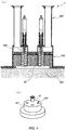
- FIG. 1 is a schematic diagram illustrating a relationship between each of the inlet nozzles 40 and the combustor 404 in the detoxification device 400 according to the present embodiment.
- a portion close to the combustor (detoxification chamber) 404 of the inlet nozzle 40 is cut (removed) to shorten the inlet nozzle 40 by a given length.
- a portion of the inlet nozzle 40 on which, when the metallic exhaust gas is allowed to flow, the metallic exhaust gas is normally precipitated as the metallic product to be gradually deposited with time is removed in advance.
- the insulator 700 which is made of a ceramic material, supplies a smaller number of electrons than that of electrons supplied from the inlet nozzle 40 made of a stainless steel. As a result, even when the metallic exhaust gas is allowed to flow, it is possible to prevent the metallic exhaust gas from being precipitated as the metallic product and solidly adhering to the place.
- FIG. 2 is a diagram illustrating an example of a schematic configuration for illustrating a system layout in which the detoxification device 400 including the inlet nozzles 40 according to the embodiment of the present invention is disposed.
- the detoxification device 400 in which the inlet nozzles 40 are disposed is a combustion type detoxification device.
- the detoxification device 400 in which the inlet nozzles 40 according to the embodiment of the present invention are disposed is not limited to the combustion type. Instead, the inlet nozzles 40 according to the present embodiment can also be disposed in, e.g., the detoxification device 400 of a heater type or a gasoline-engine type or the like.
- the dry pump 300 is further connected to the detoxification device 400 via an exhaust pipe 600.
- a casing forming a housing of the detoxification device 400 has a substantially cylindrical shape and has an upper end configured to have an inlet head 403 ( FIG. 3 ) serving as a lid portion.
- the casing need not necessarily have the substantially cylindrical shape as long as the casing is configured to have an inner space isolated from an outside thereof.
- FIG. 3 is a diagram illustrating an example of a schematic configuration of the detoxification device 400 in which the inlet nozzles 40 according to the embodiment of the present invention are disposed.
- Arrows G in the drawing represent flows of the exhaust gas containing a gas to be detoxified.
- the exhaust gas containing a toxic gas exhausted from the processing device 100 passes through the vacuum pipe 500, goes through the dry pump 300, and passes through the exhaust pipe 600 to be delivered to the detoxification device 400.
- an inlet three-way valve 401 divides the exhaust gas into an exhaust gas to be exhausted into a combustible exhaust duct and an exhaust gas to be transferred to the combustor (combustion furnace) 404.
- the exhaust gas passes through an inlet pipe 402 and then goes through the inlet head (gas inlet port) 403 to be delivered to the combustor 404.
- the combustor 404 is a space in which the gas to be detoxified containing the toxic gas is to be subjected to combustion processing, and a temperature in the combustor 404 is approximately around 800°C.
- the insulator 700 is disposed for heat insulation and, in the insulator 700, the inlet nozzles 400 are embedded.
- the detoxification device 400 includes the combustor 404 serving as the combustion furnace and a quench 405 serving as an exhaust gas cooler.
- a gas to be processed such as a combustible gas or a cleaning gas exhausted from a Chemical Vapor Deposition (CVD) device for a semiconductor manufacturing process, which is not shown, via the vacuum pump 300 such as the dry pump is introduced, via the inlet pipe 402, from the inlet head 403 disposed at an upstream end of the combustor 404 and serving as the inlet port of the detoxification device 400.
- the combustor 404 combusts and decomposes the introduced gas to be processed at a high temperature.
- Examples of the combustible gas include a colorless toxic silane (SiH 4 ) gas, a colorless (yellow) toxic highpressure tungsten hexafluoride (WF 6 ) gas, and dichlorosilane (SiH 2 Cl 2 ).
- Examples of the cleaning gas include ammonium (NH 3 ).
- the exhaust gas exhausted from the vacuum pump and introduced into the combustor 404 from the inlet head 403 is combusted and decomposed by the combustor 404.
- the toxic gas contained in the exhaust gas is detoxified.
- An exhaust gas resulting from the combustion/decomposition is cooled from about 800°C to about 80°C by the quench 405 serving as the gas cooler. Note that, for the cooling of the exhaust gas, cooling water is used.
- the cooled exhaust gas and fine particle dust resulting from the combustion/decomposition are exhausted from an exhaust port (downstream end) of the combustor 404 to be introduced into a packed tower 407 serving as a wet detoxifier through a cyclone 406 serving as a powder remover.
- a water-soluble gas such as hydrogen fluoride (HF) or hydrogen chloride (HCl) is dissolved in this portion.
- the exhaust gas is transferred to an acid exhaust duct to be exhausted.
- each of the cyclone 406 and the packed tower 407 is formed of polypropylene.
- FIGS. 4A and 4B are diagrams for illustrating a periphery of the inlet head 403 in the detoxification device 400 including the inlet nozzles 40 according to the embodiment of the present invention.
- FIG. 4A illustrates an overall view of a portion ⁇ (the inlet pipe 402, the inlet head 403, the combustor 404, and a scraper 408 described later) in FIG. 3 , which is a cross-sectional view along an axial direction.
- FIG. 4B illustrates a view obtained by viewing the portion ⁇ (the inlet nozzles 40 and the inlet head 403) in FIG. 3 from an upstream side in the flows of the exhaust gas.
- the inlet head 403 is configured to be include four inlet holes 409 in which the inlet nozzles 40 are disposed.
- the number of the inlet holes 409 can appropriately be changed to 6, 8, or the like as required.
- a material of the inlet head 403 according to the embodiment of the present invention is preferably stainless steel in terms of heat resistance and workability.
- the scraper 408 for removing a deposit adhering to a downstream end (closer to the combustor 404) of the inlet nozzle 40 is deposited.
- the deposit of the precipitated product is scraped off by the scraper 408 to be removed.
- the product derived from the metallic exhaust gas has an extremely high hardness and, once deposited, the product is extremely hard to remove.
- the scraper 408 is configured in the form of an elastic body (spring), but the configuration of the scraper 408 is not limited thereto.
- the scraper 408 may also be configured in the form of a rod, a blade, or a paddle.
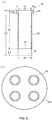
- FIGS. 5A and 5B are diagrams for illustrating each of the inlet nozzles 40 according to the embodiment of the present invention.
- FIG. 5A is a diagram illustrating a cross section of each of the inlet nozzles 40 along the axial direction.
- FIG. 5B is a diagram obtained by viewing the inlet head 403 in which the inlet nozzles 40 are disposed from below (from a downstream side when the exhaust gas flows).
- the inlet nozzle 40 has a lower end thereof adjacent to the combustor 404.
- the material of the inlet nozzles 40 according to the present embodiment is stainless steel.
- the material of the inlet nozzles 40 according to the present embodiment may also be Inconel (registered trademark), which is a nickel-base superalloy, or hastelloy (metal precipitation inhibiting structure).
- Each of the inlet nozzles 40 is a component that provides communication between the inlet pipe 402 and the inlet head 403 in the detoxification device 400, which is substantially a casing having an inner void and includes a flange portion 41, a casing side portion 42, a cut surface 43, a (former bottom portion 44), and the like.
- the flange portion 41 is located in an upper half of the inlet nozzle 40 in the axial direction (i.e., on the upstream side of a flowing gas) to be fitted into the inlet pipe 402.
- the casing side portion 42 forms a side surface of the inlet nozzle 40, which is a cylindrical casing in the present embodiment and fitted into any of the inlet holes 409 provided in the inlet head 403.
- each of the inlet nozzles 40 is configured such that a length (before cutting) L1 of the entire inlet nozzle 40 in the axial direction is about 76.6 millimeters, a length L2 of a cut portion is 10.0 millimeters, and a length L4 of the flange portion 41 in the axial direction is 6 millimeters. Accordingly, a length L3 of the inlet nozzle 40 in the axial direction after cutting is 66.6 millimeters.
- the length (before cutting) L1 of the entire inlet nozzle 40 in the axial direction corresponds to a thickness of the insulator 700 in the axial direction in FIG. 1 . Consequently, the exposed portion W of the insulator in FIG. 1 has an axial length of 10.0 millimeters.
- the length of the cut portion in the present embodiment corresponds to a portion on which, when the metallic exhaust gas is allowed to flow, the metallic exhaust gas is precipitated as the metallic product to be deposited.
- the portion of the inlet nozzle 40 close to the combustor 404 which receives a large amount of heat from the combustor 404 is cut in advance.
- the length of the cut portion is set appropriately depending on such conditions as a type of the metallic exhaust gas allowed to flow and a temperature of the combustor 404.
- the length of the cut portion preferably accounts for about 4% to 20%, or more preferably about 10% ⁇ 3-4% of the total pre-cutting length of the inlet nozzle 40.
- each of the inlet nozzles 40 is configured such that an outer diameter d1 of the flange portion 41 of the inlet nozzle 40 is 33 millimeters, an inner diameter (inner diameter of an upper portion of the casing of the inlet nozzle 40) d2 of the flange portion 41 is 24 millimeters, and an outer diameter d3 of the casing side portion 42 is 26.7 millimeters.
- the exhaust gas (metallic exhaust gas) introduced from the inlet pipe 402 passes through the inlet nozzles 40 to be transferred to the combustor 404.
- the exhaust gas (metallic exhaust gas) is allowed to flow, while being kept in contact with the exposed portion W of the insulator 700, to flow into the combustor 404.
- an inner surface (portion in contact with the metallic exhaust gas) of the inlet nozzle 40 is preferably made of a material as smooth as possible or in a condition as smooth as possible.
- the metallic product is less likely to adhere thereto or, even when the metallic product adheres to the surface of the inlet nozzle 40, the metallic product easily peels away.
- the inlet nozzles 40 made of an insulating material are used.
- an insulating material metal precipitation inhibiting structure
- each of the inlet nozzles 40 which is adjacent to the combustor 404, is heated to a considerably high temperature, and therefore a material having a high heat resistance is desirable.
- a material to be used preferably has an insulating property, a heat resistance, and a spreadability in consideration of workability.
- the material include free-machining ceramics (machinable ceramics).
- embodiments of the present invention may also be configured to be combined with each other.
Landscapes
- Engineering & Computer Science (AREA)
- Chemical & Material Sciences (AREA)
- Environmental & Geological Engineering (AREA)
- Mechanical Engineering (AREA)
- General Engineering & Computer Science (AREA)
- General Chemical & Material Sciences (AREA)
- Chemical Kinetics & Catalysis (AREA)
- Combustion & Propulsion (AREA)
- Oil, Petroleum & Natural Gas (AREA)
- Health & Medical Sciences (AREA)
- Biomedical Technology (AREA)
- Analytical Chemistry (AREA)
- Metallurgy (AREA)
- Organic Chemistry (AREA)
- Dispersion Chemistry (AREA)
- Materials Engineering (AREA)
- Incineration Of Waste (AREA)
- Treating Waste Gases (AREA)
- Gas Burners (AREA)
- Gasification And Melting Of Waste (AREA)
Abstract
Description
- The present invention relates to a detoxification device and an inlet nozzle. More particularly, the present invention relates to a detoxification device that reduces deposition of a metallic precipitate and to an inlet nozzle provided in the detoxification device.
- In a device for film deposition as one of process steps when a semiconductor, a solar battery, a liquid crystal, or the like is manufactured, a process gas such as a silane (SiH4) gas is used in a vacuum chamber for generating a Si film.
- A discharged gas (exhaust gas) after being used is exhausted to an outside of the vacuum chamber serving as a device for a semiconductor manufacturing process by a vacuum pump connected to the vacuum chamber. In most cases, such a discharged gas contains various toxic gases resulting from a film deposition step, such as the silane gas described above, tungsten hexafluoride (WF6), and dichlorosilane (SiH2Cl2). Accordingly, to an exhaust side of the vacuum pump, a detoxification device is connected to oxidize such a discharged gas and exhaust the discharged gas as a harmless gas.
- This detoxification device comes in various types such as a combustion type and a plasma type. In the case of a combustion type detoxification device, for example, an oxidative reaction in which the discharged gas is burned to react with air (oxygen) is caused to change the toxic gas to a harmless gas.
-
FIG. 6 is a schematic diagram illustrating a configuration of each of an inlet nozzle 1040 and a combustor (combustion furnace) 1404 in an existingdetoxification device 1400. - As illustrated in the drawing, an
insulator 1700 serving as an insulating material is provided adjacent to thecombustor 1404. An inlet nozzle 1040 having a length corresponding to a thickness of theinsulator 1700 is provided in theinsulator 1700 to extend therethrough. Thedetoxification device 1400 is configured such that an exhaust gas is transferred to thecombustor 1404 through the inlet nozzle 1040. - When an exhaust gas (hereinafter referred to as the metallic exhaust gas) containing a metal (e.g., titanium or tungsten hexafluoride) is transferred to the
combustor 404 through theinlet nozzle 40, under radiation of heat from thecombustor 1404, a reductive reaction occurs at a tip portion (portion adjacent to the combustor 1404) of the inlet nozzle 140. Consequently, the exhaust gas is precipitated as a metallic product to be gradually deposited as a metallic product X with time. - A phenomenon in which the metallic product is precipitated is caused by a high temperature and a supply of electrons (supply from the inlet nozzle 1040 made of stainless steel).
- The metallic product X has an extremely high hardness and, once the metallic product X is deposited, it is difficult to remove the metallic product X by using a scraper 1408 (see
FIG. 4A , a device for scraping off a deposit). Specifically, as illustrated inFIG. 6 , the metallic product X is so solidly fixed as to stop movement of thescraper 1408. When this state is left untreated, a flow path is gradually clogged. - As a result, a problem of a shorter maintenance (overhaul) cycle for the
detoxification device 1400 arises. - An object of the present invention is to provide an inlet nozzle capable of reducing an amount of a deposit of an adhering metallic product and elongating a maintenance cycle and a detoxification device including the inlet nozzle.
- The invention claimed in
claim 1 provides a detoxification device including: a detoxification chamber; an insulator provided adjacent to the detoxification chamber and made of an insulating material; and an inlet nozzle embedded in the insulator to guide an exhaust gas to be detoxified to the detoxification chamber, the inlet nozzle including a metal precipitation inhibiting structure. - The invention claimed in claim 2 provides the detoxification device according to
claim 1 wherein a portion of the inlet nozzle adjacent to the detoxification chamber has a length set shorter by a predetermined length than an original entire length of the inlet nozzle to expose the insulator. - The invention claimed in claim 3 provides the detoxification device according to claim 2 wherein a portion set to shorten the inlet nozzle corresponds to a portion on which a metallic product is deposited when the exhaust gas which is a metallic exhaust gas is allowed to flow in a state before the inlet nozzle is shortened.
- The invention claimed in
claim 4 provides the detoxification device according toclaim 1 wherein the inlet nozzle is formed of an insulating material. - The invention claimed in claim 5 provides an inlet nozzle including: a metal precipitation inhibiting structure, the inlet nozzle being provided in a detoxification device including a detoxification chamber and an insulator provided adjacent to the detoxification chamber and made of an insulating material, the inlet nozzle being embedded in the insulator to guide an exhaust gas to be detoxified to the detoxification chamber.
- According to the present invention, it is possible to provide the inlet nozzle using the metal precipitation inhibiting structure provided therein to reduce an amount of a deposit of the metallic product adhering to a tip portion of the inlet nozzle and elongate a maintenance cycle as well as a detoxification device including the inlet nozzle.
-
-
FIG. 1 is a schematic diagram illustrating a configuration of each of inlet nozzles and a combustor in a detoxification device according to the present invention; -
FIG. 2 is a diagram illustrating an example of a schematic configuration for illustrating a system layout in which the detoxification device including the inlet nozzles according to the present invention is disposed; -
FIG. 3 is a diagram illustrating an example of a schematic configuration of the detoxification device including the inlet nozzles according to the present invention; -
FIGS. 4A and 4B are diagrams for illustrating a periphery of an inlet head in the detoxification device including the inlet nozzles according to the present invention; -
FIGS. 5A and 5B are diagrams for illustrating each of the inlet nozzles according to the present invention; and -
FIG. 6 is a schematic diagram illustrating a configuration of each of an inlet nozzle and a combustor in an existing detoxification device. - From each of
inlet nozzles 40 according to the present embodiment, a portion adjacent to acombustor 404, i.e., a portion to which a metallic product adheres to be deposited thereon is cut (removed) in advance. Consequently, in the portion, aninsulator 700 made of a ceramic material is exposed (metal precipitation inhibiting structure). Since the ceramic material supplies a small number of electrons, even when theinsulator 700 is exposed to heat from thecombustor 404 to reach a high temperature, a reductive reaction is less likely to occur. - Accordingly, even when a metallic exhaust gas is allowed to flow, it is possible to inhibit the metallic exhaust gas from being precipitated as the metallic product and gradually deposited with time.
- As a result, it is possible to reduce a deposit adhering to the portion adjacent to the
combustor 404 and consequently elongate a maintenance cycle for adetoxification device 400. - Referring to
FIGS. 1 to 5 , a detailed description will be given below of each of preferred embodiments of the present invention. -
FIG. 1 is a schematic diagram illustrating a relationship between each of theinlet nozzles 40 and thecombustor 404 in thedetoxification device 400 according to the present embodiment. - From each of the
inlet nozzles 40 according to the present embodiment, a portion close to the combustor (detoxification chamber) 404 of theinlet nozzle 40 is cut (removed) to shorten theinlet nozzle 40 by a given length. In other words, a portion of theinlet nozzle 40 on which, when the metallic exhaust gas is allowed to flow, the metallic exhaust gas is normally precipitated as the metallic product to be gradually deposited with time is removed in advance. - Consequently, a portion of the
insulator 700 adjacent to thecombustor 404 is exposed to a path for the exhaust gas (exposed portion W). Theinsulator 700, which is made of a ceramic material, supplies a smaller number of electrons than that of electrons supplied from theinlet nozzle 40 made of a stainless steel. As a result, even when the metallic exhaust gas is allowed to flow, it is possible to prevent the metallic exhaust gas from being precipitated as the metallic product and solidly adhering to the place. - Due to this configuration, even when the exposed portion W of the
insulator 700 is exposed to radiation of heat from thecombustor 404, a reductive reaction is less likely to occur in the exposed portion W of theinsulator 700 to prevent the metallic exhaust gas from being precipitated as the metallic product and being gradually deposited with time. - As a result, it is possible to reduce the deposit adhering to the portion adjacent to the
combustor 404 and consequently elongate a maintenance cycle for thedetoxification device 400. -
FIG. 2 is a diagram illustrating an example of a schematic configuration for illustrating a system layout in which thedetoxification device 400 including theinlet nozzles 40 according to the embodiment of the present invention is disposed. - In the embodiment, it is assumed by way of example that the
detoxification device 400 in which theinlet nozzles 40 are disposed is a combustion type detoxification device. However, thedetoxification device 400 in which the inlet nozzles 40 according to the embodiment of the present invention are disposed is not limited to the combustion type. Instead, theinlet nozzles 40 according to the present embodiment can also be disposed in, e.g., thedetoxification device 400 of a heater type or a gasoline-engine type or the like. - A processing device (processing chamber) 100 disposed in a
clean room 200, such as a wafer deposition device, is connected to adry pump 300 via avacuum pipe 500. Thedry pump 300 is further connected to thedetoxification device 400 via anexhaust pipe 600. - A casing forming a housing of the
detoxification device 400 has a substantially cylindrical shape and has an upper end configured to have an inlet head 403 (FIG. 3 ) serving as a lid portion. The casing need not necessarily have the substantially cylindrical shape as long as the casing is configured to have an inner space isolated from an outside thereof. -
FIG. 3 is a diagram illustrating an example of a schematic configuration of thedetoxification device 400 in which theinlet nozzles 40 according to the embodiment of the present invention are disposed. Arrows G in the drawing represent flows of the exhaust gas containing a gas to be detoxified. - The exhaust gas containing a toxic gas exhausted from the
processing device 100 passes through thevacuum pipe 500, goes through thedry pump 300, and passes through theexhaust pipe 600 to be delivered to thedetoxification device 400. - Then, an inlet three-
way valve 401 divides the exhaust gas into an exhaust gas to be exhausted into a combustible exhaust duct and an exhaust gas to be transferred to the combustor (combustion furnace) 404. - The exhaust gas passes through an
inlet pipe 402 and then goes through the inlet head (gas inlet port) 403 to be delivered to thecombustor 404. - The
combustor 404 is a space in which the gas to be detoxified containing the toxic gas is to be subjected to combustion processing, and a temperature in thecombustor 404 is approximately around 800°C. In theinlet head 403, theinsulator 700 is disposed for heat insulation and, in theinsulator 700, theinlet nozzles 400 are embedded. - The
detoxification device 400 according to the present embodiment includes thecombustor 404 serving as the combustion furnace and a quench 405 serving as an exhaust gas cooler. - Into the
combustor 404, a gas to be processed such as a combustible gas or a cleaning gas exhausted from a Chemical Vapor Deposition (CVD) device for a semiconductor manufacturing process, which is not shown, via thevacuum pump 300 such as the dry pump is introduced, via theinlet pipe 402, from theinlet head 403 disposed at an upstream end of thecombustor 404 and serving as the inlet port of thedetoxification device 400. Thecombustor 404 combusts and decomposes the introduced gas to be processed at a high temperature. - Examples of the combustible gas include a colorless toxic silane (SiH4) gas, a colorless (yellow) toxic highpressure tungsten hexafluoride (WF6) gas, and dichlorosilane (SiH2Cl2). Examples of the cleaning gas include ammonium (NH3).
- In the present embodiment, the exhaust gas exhausted from the vacuum pump and introduced into the combustor 404 from the
inlet head 403 is combusted and decomposed by thecombustor 404. By the combustion/decomposition, the toxic gas contained in the exhaust gas is detoxified. - An exhaust gas resulting from the combustion/decomposition is cooled from about 800°C to about 80°C by the
quench 405 serving as the gas cooler. Note that, for the cooling of the exhaust gas, cooling water is used. - Then, the cooled exhaust gas and fine particle dust resulting from the combustion/decomposition are exhausted from an exhaust port (downstream end) of the
combustor 404 to be introduced into a packedtower 407 serving as a wet detoxifier through acyclone 406 serving as a powder remover. A water-soluble gas such as hydrogen fluoride (HF) or hydrogen chloride (HCl) is dissolved in this portion. Then, the exhaust gas is transferred to an acid exhaust duct to be exhausted. - Note that, in the present embodiment, each of the
cyclone 406 and the packedtower 407 is formed of polypropylene. -
FIGS. 4A and 4B are diagrams for illustrating a periphery of theinlet head 403 in thedetoxification device 400 including theinlet nozzles 40 according to the embodiment of the present invention.
FIG. 4A illustrates an overall view of a portion α (theinlet pipe 402, theinlet head 403, thecombustor 404, and ascraper 408 described later) inFIG. 3 , which is a cross-sectional view along an axial direction.FIG. 4B illustrates a view obtained by viewing the portion α (theinlet nozzles 40 and the inlet head 403) inFIG. 3 from an upstream side in the flows of the exhaust gas. - In the present embodiment, by way of example, the
inlet head 403 is configured to be include fourinlet holes 409 in which theinlet nozzles 40 are disposed. However, the number of the inlet holes 409 can appropriately be changed to 6, 8, or the like as required. - Note that, by way of example, a material of the
inlet head 403 according to the embodiment of the present invention is preferably stainless steel in terms of heat resistance and workability. - In each of the
inlet nozzles 40, thescraper 408 for removing a deposit adhering to a downstream end (closer to the combustor 404) of theinlet nozzle 40 is deposited. - When the exhaust gas is allowed to flow, the deposit of the precipitated product is scraped off by the
scraper 408 to be removed. However, the product derived from the metallic exhaust gas has an extremely high hardness and, once deposited, the product is extremely hard to remove. - Note that, in the present embodiment, the
scraper 408 is configured in the form of an elastic body (spring), but the configuration of thescraper 408 is not limited thereto. For example, thescraper 408 may also be configured in the form of a rod, a blade, or a paddle. -
FIGS. 5A and 5B are diagrams for illustrating each of theinlet nozzles 40 according to the embodiment of the present invention. -
FIG. 5A is a diagram illustrating a cross section of each of theinlet nozzles 40 along the axial direction.FIG. 5B is a diagram obtained by viewing theinlet head 403 in which theinlet nozzles 40 are disposed from below (from a downstream side when the exhaust gas flows). Theinlet nozzle 40 has a lower end thereof adjacent to thecombustor 404. - As described above, the material of the
inlet nozzles 40 according to the present embodiment is stainless steel. Instead, the material of theinlet nozzles 40 according to the present embodiment may also be Inconel (registered trademark), which is a nickel-base superalloy, or hastelloy (metal precipitation inhibiting structure). - Each of the
inlet nozzles 40 according to the present embodiment is a component that provides communication between theinlet pipe 402 and theinlet head 403 in thedetoxification device 400, which is substantially a casing having an inner void and includes aflange portion 41, acasing side portion 42, acut surface 43, a (former bottom portion 44), and the like. - The
flange portion 41 is located in an upper half of theinlet nozzle 40 in the axial direction (i.e., on the upstream side of a flowing gas) to be fitted into theinlet pipe 402. - The
casing side portion 42 forms a side surface of theinlet nozzle 40, which is a cylindrical casing in the present embodiment and fitted into any of the inlet holes 409 provided in theinlet head 403. - By way of example, each of the
inlet nozzles 40 according to the present embodiment is configured such that a length (before cutting) L1 of theentire inlet nozzle 40 in the axial direction is about 76.6 millimeters, a length L2 of a cut portion is 10.0 millimeters, and a length L4 of theflange portion 41 in the axial direction is 6 millimeters. Accordingly, a length L3 of theinlet nozzle 40 in the axial direction after cutting is 66.6 millimeters. The length (before cutting) L1 of theentire inlet nozzle 40 in the axial direction corresponds to a thickness of theinsulator 700 in the axial direction inFIG. 1 . Consequently, the exposed portion W of the insulator inFIG. 1 has an axial length of 10.0 millimeters. - The length of the cut portion in the present embodiment corresponds to a portion on which, when the metallic exhaust gas is allowed to flow, the metallic exhaust gas is precipitated as the metallic product to be deposited. In other words, the portion of the
inlet nozzle 40 close to thecombustor 404 which receives a large amount of heat from thecombustor 404 is cut in advance. The length of the cut portion is set appropriately depending on such conditions as a type of the metallic exhaust gas allowed to flow and a temperature of thecombustor 404. - However, cutting off fifty percent or more of the
inlet nozzle 40 is not desirable because a function of theinlet nozzle 40 serving as a guide for the exhaust gas may be disturbed. In the present embodiment, the length of the cut portion preferably accounts for about 4% to 20%, or more preferably about 10%±3-4% of the total pre-cutting length of theinlet nozzle 40. - Note that, even when the
inlet nozzle 40 is cut, a portion thereof close to thecut surface 43 still receives an amount of heat from thecombustor 404. However, since the portion close to thecut surface 43 is farther away from thecombustor 404 than theformer bottom portion 44 which used to be a bottom surface of theinlet nozzle 40, the amount of the received heat decreases to be able to inhibit the generation of the metallic product. - By way of example, each of the
inlet nozzles 40 according to the embodiment of the present invention is configured such that an outer diameter d1 of theflange portion 41 of theinlet nozzle 40 is 33 millimeters, an inner diameter (inner diameter of an upper portion of the casing of the inlet nozzle 40) d2 of theflange portion 41 is 24 millimeters, and an outer diameter d3 of thecasing side portion 42 is 26.7 millimeters. - Due to the configuration described above, in the
detoxification device 400 in which theinlet nozzles 40 according to the present embodiment are disposed, the exhaust gas (metallic exhaust gas) introduced from theinlet pipe 402 passes through theinlet nozzles 40 to be transferred to thecombustor 404. In addition, since a lower end portion of each of the inlet nozzles 40 is shortened, the exhaust gas (metallic exhaust gas) is allowed to flow, while being kept in contact with the exposed portion W of theinsulator 700, to flow into thecombustor 404. - Note that an inner surface (portion in contact with the metallic exhaust gas) of the
inlet nozzle 40 is preferably made of a material as smooth as possible or in a condition as smooth as possible. When the surface of theinlet nozzle 40 is smooth, the metallic product is less likely to adhere thereto or, even when the metallic product adheres to the surface of theinlet nozzle 40, the metallic product easily peels away. - In a second embodiment, the
inlet nozzles 40 made of an insulating material (metal precipitation inhibiting structure) are used. By producing theinlet nozzles 40 of the insulating material, electrons supplied therefrom are reduced, and the reductive reaction is less likely to occur in the metallic exhaust gas. As a result, it is possible to inhibit the metallic product from being deposited. - However, the tip portion of each of the
inlet nozzles 40, which is adjacent to thecombustor 404, is heated to a considerably high temperature, and therefore a material having a high heat resistance is desirable. - Accordingly, a material to be used preferably has an insulating property, a heat resistance, and a spreadability in consideration of workability.
- Specific examples of the material include free-machining ceramics (machinable ceramics).
- As required, the embodiments of the present invention may also be configured to be combined with each other.
- In addition, various modifications can be made in the present invention without departing from the spirit of the present invention. It is intended that the present invention covers such modifications
-
- 40
- Inlet nozzle
- 41
- Flange portion
- 42
- Casing side portion
- 43
- Cut surface
- 44
- Former bottom portion (before cutting)
- 100
- Processing device
- 200
- Clean room
- 300
- Dry pump (vacuum pump)
- 400
- Detoxification device
- 401
- Inlet three-way valve
- 402
- Inlet pipe
- 403
- Inlet head
- 404
- Combustor
- 405
- Quench
- 406
- Cyclone
- 407
- Packed tower
- 408
- Scraper
- 409
- Inlet hole
- 500
- Vacuum pipe
- 600
- Exhaust pipe
- 700
- Insulator
- W
- Exposed portion
- X
- Metallic product
Claims (5)
- A detoxification device comprising:a detoxification chamber;an insulator provided adjacent to the detoxification chamber and made of an insulating material; andan inlet nozzle embedded in the insulator to guide an exhaust gas to be detoxified to the detoxification chamber,the inlet nozzle including a metal precipitation inhibiting structure.
- The detoxification device according to claim 1, wherein a portion of the inlet nozzle adjacent to the detoxification chamber has a length set shorter by a predetermined length to expose the insulator.
- The detoxification device according to claim 2, wherein a portion set to shorten the inlet nozzle corresponds to a portion on which a metallic product is deposited when the exhaust gas which is a metallic exhaust gas is allowed to flow in a state before the inlet nozzle is shortened.
- The detoxification device according to claim 1, wherein the inlet nozzle is formed of an insulating material.
- An inlet nozzle comprising:a metal precipitation inhibiting structure,the inlet nozzle being provided in a detoxification device including a detoxification chamber and an insulator provided adjacent to the detoxification chamber and formed of an insulating material,the inlet nozzle being embedded in the insulator to guide an exhaust gas to be detoxified to the detoxification chamber.
Applications Claiming Priority (2)
| Application Number | Priority Date | Filing Date | Title |
|---|---|---|---|
| JP2018113898A JP7252718B2 (en) | 2018-06-14 | 2018-06-14 | Abatement device and inlet nozzle |
| PCT/JP2019/021926 WO2019239935A1 (en) | 2018-06-14 | 2019-06-03 | Damage-reducing apparatus and inlet nozzle |
Publications (3)
| Publication Number | Publication Date |
|---|---|
| EP3809042A1 true EP3809042A1 (en) | 2021-04-21 |
| EP3809042A4 EP3809042A4 (en) | 2022-06-01 |
| EP3809042B1 EP3809042B1 (en) | 2025-04-16 |
Family
ID=68843335
Family Applications (1)
| Application Number | Title | Priority Date | Filing Date |
|---|---|---|---|
| EP19819498.7A Active EP3809042B1 (en) | 2018-06-14 | 2019-06-03 | Detoxification device |
Country Status (6)
| Country | Link |
|---|---|
| US (1) | US12303829B2 (en) |
| EP (1) | EP3809042B1 (en) |
| JP (1) | JP7252718B2 (en) |
| KR (1) | KR102921976B1 (en) |
| CN (1) | CN112189114A (en) |
| WO (1) | WO2019239935A1 (en) |
Families Citing this family (1)
| Publication number | Priority date | Publication date | Assignee | Title |
|---|---|---|---|---|
| GB2608822A (en) * | 2021-07-13 | 2023-01-18 | Edwards Ltd | Inlet nozzle assembly |
Family Cites Families (10)
| Publication number | Priority date | Publication date | Assignee | Title |
|---|---|---|---|---|
| US4668180A (en) * | 1982-11-24 | 1987-05-26 | Newman Ray L | Ceramic burner having high turndown ratio |
| JP3608671B2 (en) * | 1995-05-17 | 2005-01-12 | 東京瓦斯株式会社 | Furnace apparatus and combustion method |
| US5931654A (en) * | 1997-06-30 | 1999-08-03 | Praxair Technology, Inc. | Recessed furnace lance purge gas system |
| JP2001355825A (en) | 2000-06-12 | 2001-12-26 | Sumitomo Seika Chem Co Ltd | Treating method and treating device for waste gas |
| JP2002276921A (en) * | 2001-03-23 | 2002-09-25 | Babcock Hitachi Kk | Silane removing apparatus |
| GB0417378D0 (en) * | 2004-08-04 | 2004-09-08 | Boc Group Plc | Gas abatement |
| JP2014134350A (en) * | 2013-01-11 | 2014-07-24 | Edwards Kk | Inlet nozzle and detoxification device |
| JP6113029B2 (en) | 2013-09-05 | 2017-04-12 | エドワーズ株式会社 | Removal device and abatement device |
| CN105090999B (en) * | 2014-05-12 | 2018-11-20 | 日本派欧尼株式会社 | The combustion-type purification device of exhaust gas |
| JP6777472B2 (en) * | 2016-09-06 | 2020-10-28 | エドワーズ株式会社 | Abatement equipment and deposit removal means used in abatement equipment |
-
2018
- 2018-06-14 JP JP2018113898A patent/JP7252718B2/en active Active
-
2019
- 2019-06-03 EP EP19819498.7A patent/EP3809042B1/en active Active
- 2019-06-03 WO PCT/JP2019/021926 patent/WO2019239935A1/en not_active Ceased
- 2019-06-03 KR KR1020207034991A patent/KR102921976B1/en active Active
- 2019-06-03 US US16/972,843 patent/US12303829B2/en active Active
- 2019-06-03 CN CN201980036401.3A patent/CN112189114A/en active Pending
Also Published As
| Publication number | Publication date |
|---|---|
| JP7252718B2 (en) | 2023-04-05 |
| US20210245093A1 (en) | 2021-08-12 |
| WO2019239935A1 (en) | 2019-12-19 |
| US12303829B2 (en) | 2025-05-20 |
| KR20210020005A (en) | 2021-02-23 |
| CN112189114A (en) | 2021-01-05 |
| EP3809042B1 (en) | 2025-04-16 |
| JP2019215146A (en) | 2019-12-19 |
| KR102921976B1 (en) | 2026-02-03 |
| EP3809042A4 (en) | 2022-06-01 |
Similar Documents
| Publication | Publication Date | Title |
|---|---|---|
| KR102688002B1 (en) | In-situ CVD and ALD coating of chambers to control metal contamination | |
| KR101411964B1 (en) | Gas treatment device | |
| US7976807B2 (en) | Method for detoxifying HCD gas and apparatus therefor | |
| JP6873040B2 (en) | Gas processing equipment | |
| EP2105409B1 (en) | Polymer inactivation method for polycrystalline silicon manufacturing device | |
| EP3809042B1 (en) | Detoxification device | |
| WO2014109152A1 (en) | Inlet nozzle and detoxification device | |
| KR20010039780A (en) | A hot element cvd apparatus and a method for removing a deposited film | |
| KR102077759B1 (en) | Gas exhausting equipment and method for inhibiting deposition of powder in exhaust pipe for semiconductor production facility | |
| JP2011233583A (en) | Vapor-phase growth device and method of manufacturing silicon epitaxial wafer | |
| CN103871930A (en) | Semiconductor manufacturing apparatus having control function of powder generation | |
| JP6113029B2 (en) | Removal device and abatement device | |
| JP4541739B2 (en) | Semiconductor device manufacturing method, cleaning method, and semiconductor device manufacturing apparatus | |
| JP3780307B2 (en) | Method for cleaning epitaxial growth furnace system | |
| EP2744587B1 (en) | Apparatus for treating a gas stream | |
| Chen | Characteristics of fire and explosion in semiconductor fabrication processes | |
| JP3215074B2 (en) | Method and device for removing semiconductor manufacturing flue gas | |
| JP5087653B2 (en) | Semiconductor device manufacturing method, cleaning method, and substrate processing apparatus | |
| JP2005187842A (en) | Exhaust system and maintenance method thereof | |
| KR20250037529A (en) | Vacuum exhaust system and cleaning method | |
| JP5297661B2 (en) | Vapor growth equipment | |
| JP6321997B2 (en) | Detoxifying device, scraping part and bearing device used in the detoxifying device | |
| JP2009088009A (en) | Vapor growth apparatus and vapor growth method | |
| WO1999030809A1 (en) | Method and device for treating exhaust gas | |
| US20090159005A1 (en) | Coatings for semiconductor processing equipment |
Legal Events
| Date | Code | Title | Description |
|---|---|---|---|
| STAA | Information on the status of an ep patent application or granted ep patent |
Free format text: STATUS: THE INTERNATIONAL PUBLICATION HAS BEEN MADE |
|
| PUAI | Public reference made under article 153(3) epc to a published international application that has entered the european phase |
Free format text: ORIGINAL CODE: 0009012 |
|
| STAA | Information on the status of an ep patent application or granted ep patent |
Free format text: STATUS: REQUEST FOR EXAMINATION WAS MADE |
|
| 17P | Request for examination filed |
Effective date: 20201216 |
|
| AK | Designated contracting states |
Kind code of ref document: A1 Designated state(s): AL AT BE BG CH CY CZ DE DK EE ES FI FR GB GR HR HU IE IS IT LI LT LU LV MC MK MT NL NO PL PT RO RS SE SI SK SM TR |
|
| AX | Request for extension of the european patent |
Extension state: BA ME |
|
| DAV | Request for validation of the european patent (deleted) | ||
| DAX | Request for extension of the european patent (deleted) | ||
| A4 | Supplementary search report drawn up and despatched |
Effective date: 20220503 |
|
| RIC1 | Information provided on ipc code assigned before grant |
Ipc: F23G 7/00 20060101ALI20220427BHEP Ipc: F23D 14/48 20060101ALI20220427BHEP Ipc: F23G 7/06 20060101AFI20220427BHEP |
|
| STAA | Information on the status of an ep patent application or granted ep patent |
Free format text: STATUS: EXAMINATION IS IN PROGRESS |
|
| 17Q | First examination report despatched |
Effective date: 20240130 |
|
| GRAP | Despatch of communication of intention to grant a patent |
Free format text: ORIGINAL CODE: EPIDOSNIGR1 |
|
| STAA | Information on the status of an ep patent application or granted ep patent |
Free format text: STATUS: GRANT OF PATENT IS INTENDED |
|
| INTG | Intention to grant announced |
Effective date: 20241120 |
|
| GRAS | Grant fee paid |
Free format text: ORIGINAL CODE: EPIDOSNIGR3 |
|
| GRAA | (expected) grant |
Free format text: ORIGINAL CODE: 0009210 |
|
| STAA | Information on the status of an ep patent application or granted ep patent |
Free format text: STATUS: THE PATENT HAS BEEN GRANTED |
|
| AK | Designated contracting states |
Kind code of ref document: B1 Designated state(s): AL AT BE BG CH CY CZ DE DK EE ES FI FR GB GR HR HU IE IS IT LI LT LU LV MC MK MT NL NO PL PT RO RS SE SI SK SM TR |
|
| REG | Reference to a national code |
Ref country code: GB Ref legal event code: FG4D |
|
| REG | Reference to a national code |
Ref country code: CH Ref legal event code: EP Ref country code: DE Ref legal event code: R096 Ref document number: 602019068759 Country of ref document: DE |
|
| REG | Reference to a national code |
Ref country code: IE Ref legal event code: FG4D |
|
| PGFP | Annual fee paid to national office [announced via postgrant information from national office to epo] |
Ref country code: DE Payment date: 20250627 Year of fee payment: 7 |
|
| PGFP | Annual fee paid to national office [announced via postgrant information from national office to epo] |
Ref country code: GB Payment date: 20250627 Year of fee payment: 7 |
|
| PGFP | Annual fee paid to national office [announced via postgrant information from national office to epo] |
Ref country code: NL Payment date: 20250626 Year of fee payment: 7 |
|
| REG | Reference to a national code |
Ref country code: NL Ref legal event code: FP |
|
| PGFP | Annual fee paid to national office [announced via postgrant information from national office to epo] |
Ref country code: FR Payment date: 20250625 Year of fee payment: 7 |
|
| REG | Reference to a national code |
Ref country code: AT Ref legal event code: MK05 Ref document number: 1785903 Country of ref document: AT Kind code of ref document: T Effective date: 20250416 |
|
| PG25 | Lapsed in a contracting state [announced via postgrant information from national office to epo] |
Ref country code: PT Free format text: LAPSE BECAUSE OF FAILURE TO SUBMIT A TRANSLATION OF THE DESCRIPTION OR TO PAY THE FEE WITHIN THE PRESCRIBED TIME-LIMIT Effective date: 20250818 Ref country code: ES Free format text: LAPSE BECAUSE OF FAILURE TO SUBMIT A TRANSLATION OF THE DESCRIPTION OR TO PAY THE FEE WITHIN THE PRESCRIBED TIME-LIMIT Effective date: 20250416 Ref country code: FI Free format text: LAPSE BECAUSE OF FAILURE TO SUBMIT A TRANSLATION OF THE DESCRIPTION OR TO PAY THE FEE WITHIN THE PRESCRIBED TIME-LIMIT Effective date: 20250416 |
|
| REG | Reference to a national code |
Ref country code: LT Ref legal event code: MG9D |
|
| PG25 | Lapsed in a contracting state [announced via postgrant information from national office to epo] |
Ref country code: GR Free format text: LAPSE BECAUSE OF FAILURE TO SUBMIT A TRANSLATION OF THE DESCRIPTION OR TO PAY THE FEE WITHIN THE PRESCRIBED TIME-LIMIT Effective date: 20250717 Ref country code: NO Free format text: LAPSE BECAUSE OF FAILURE TO SUBMIT A TRANSLATION OF THE DESCRIPTION OR TO PAY THE FEE WITHIN THE PRESCRIBED TIME-LIMIT Effective date: 20250716 |
|
| PG25 | Lapsed in a contracting state [announced via postgrant information from national office to epo] |
Ref country code: PL Free format text: LAPSE BECAUSE OF FAILURE TO SUBMIT A TRANSLATION OF THE DESCRIPTION OR TO PAY THE FEE WITHIN THE PRESCRIBED TIME-LIMIT Effective date: 20250416 |
|
| PG25 | Lapsed in a contracting state [announced via postgrant information from national office to epo] |
Ref country code: BG Free format text: LAPSE BECAUSE OF FAILURE TO SUBMIT A TRANSLATION OF THE DESCRIPTION OR TO PAY THE FEE WITHIN THE PRESCRIBED TIME-LIMIT Effective date: 20250416 |
|
| PG25 | Lapsed in a contracting state [announced via postgrant information from national office to epo] |
Ref country code: HR Free format text: LAPSE BECAUSE OF FAILURE TO SUBMIT A TRANSLATION OF THE DESCRIPTION OR TO PAY THE FEE WITHIN THE PRESCRIBED TIME-LIMIT Effective date: 20250416 |
|
| PG25 | Lapsed in a contracting state [announced via postgrant information from national office to epo] |
Ref country code: AT Free format text: LAPSE BECAUSE OF FAILURE TO SUBMIT A TRANSLATION OF THE DESCRIPTION OR TO PAY THE FEE WITHIN THE PRESCRIBED TIME-LIMIT Effective date: 20250416 |
|
| PG25 | Lapsed in a contracting state [announced via postgrant information from national office to epo] |
Ref country code: RS Free format text: LAPSE BECAUSE OF FAILURE TO SUBMIT A TRANSLATION OF THE DESCRIPTION OR TO PAY THE FEE WITHIN THE PRESCRIBED TIME-LIMIT Effective date: 20250716 |
|
| PG25 | Lapsed in a contracting state [announced via postgrant information from national office to epo] |
Ref country code: IS Free format text: LAPSE BECAUSE OF FAILURE TO SUBMIT A TRANSLATION OF THE DESCRIPTION OR TO PAY THE FEE WITHIN THE PRESCRIBED TIME-LIMIT Effective date: 20250816 |
|
| PG25 | Lapsed in a contracting state [announced via postgrant information from national office to epo] |
Ref country code: LV Free format text: LAPSE BECAUSE OF FAILURE TO SUBMIT A TRANSLATION OF THE DESCRIPTION OR TO PAY THE FEE WITHIN THE PRESCRIBED TIME-LIMIT Effective date: 20250416 |
|
| PG25 | Lapsed in a contracting state [announced via postgrant information from national office to epo] |
Ref country code: DK Free format text: LAPSE BECAUSE OF FAILURE TO SUBMIT A TRANSLATION OF THE DESCRIPTION OR TO PAY THE FEE WITHIN THE PRESCRIBED TIME-LIMIT Effective date: 20250416 Ref country code: SM Free format text: LAPSE BECAUSE OF FAILURE TO SUBMIT A TRANSLATION OF THE DESCRIPTION OR TO PAY THE FEE WITHIN THE PRESCRIBED TIME-LIMIT Effective date: 20250416 |
|
| REG | Reference to a national code |
Ref country code: DE Ref legal event code: R097 Ref document number: 602019068759 Country of ref document: DE |
|
| PG25 | Lapsed in a contracting state [announced via postgrant information from national office to epo] |
Ref country code: CZ Free format text: LAPSE BECAUSE OF FAILURE TO SUBMIT A TRANSLATION OF THE DESCRIPTION OR TO PAY THE FEE WITHIN THE PRESCRIBED TIME-LIMIT Effective date: 20250416 |
|
| PG25 | Lapsed in a contracting state [announced via postgrant information from national office to epo] |
Ref country code: EE Free format text: LAPSE BECAUSE OF FAILURE TO SUBMIT A TRANSLATION OF THE DESCRIPTION OR TO PAY THE FEE WITHIN THE PRESCRIBED TIME-LIMIT Effective date: 20250416 |
|
| PG25 | Lapsed in a contracting state [announced via postgrant information from national office to epo] |
Ref country code: RO Free format text: LAPSE BECAUSE OF FAILURE TO SUBMIT A TRANSLATION OF THE DESCRIPTION OR TO PAY THE FEE WITHIN THE PRESCRIBED TIME-LIMIT Effective date: 20250416 Ref country code: SK Free format text: LAPSE BECAUSE OF FAILURE TO SUBMIT A TRANSLATION OF THE DESCRIPTION OR TO PAY THE FEE WITHIN THE PRESCRIBED TIME-LIMIT Effective date: 20250416 |
|
| REG | Reference to a national code |
Ref country code: CH Ref legal event code: H13 Free format text: ST27 STATUS EVENT CODE: U-0-0-H10-H13 (AS PROVIDED BY THE NATIONAL OFFICE) Effective date: 20260127 |
|
| PG25 | Lapsed in a contracting state [announced via postgrant information from national office to epo] |
Ref country code: IT Free format text: LAPSE BECAUSE OF FAILURE TO SUBMIT A TRANSLATION OF THE DESCRIPTION OR TO PAY THE FEE WITHIN THE PRESCRIBED TIME-LIMIT Effective date: 20250416 |
|
| PG25 | Lapsed in a contracting state [announced via postgrant information from national office to epo] |
Ref country code: MC Free format text: LAPSE BECAUSE OF FAILURE TO SUBMIT A TRANSLATION OF THE DESCRIPTION OR TO PAY THE FEE WITHIN THE PRESCRIBED TIME-LIMIT Effective date: 20250416 |
|
| PG25 | Lapsed in a contracting state [announced via postgrant information from national office to epo] |
Ref country code: LU Free format text: LAPSE BECAUSE OF NON-PAYMENT OF DUE FEES Effective date: 20250603 |
|
| PLBE | No opposition filed within time limit |
Free format text: ORIGINAL CODE: 0009261 |
|
| STAA | Information on the status of an ep patent application or granted ep patent |
Free format text: STATUS: NO OPPOSITION FILED WITHIN TIME LIMIT |
|
| REG | Reference to a national code |
Ref country code: CH Ref legal event code: L10 Free format text: ST27 STATUS EVENT CODE: U-0-0-L10-L00 (AS PROVIDED BY THE NATIONAL OFFICE) Effective date: 20260225 |
|
| REG | Reference to a national code |
Ref country code: BE Ref legal event code: MM Effective date: 20250630 |
|
| 26N | No opposition filed |
Effective date: 20260119 |
|
| PG25 | Lapsed in a contracting state [announced via postgrant information from national office to epo] |
Ref country code: IE Free format text: LAPSE BECAUSE OF NON-PAYMENT OF DUE FEES Effective date: 20250603 |
|
| PG25 | Lapsed in a contracting state [announced via postgrant information from national office to epo] |
Ref country code: BE Free format text: LAPSE BECAUSE OF NON-PAYMENT OF DUE FEES Effective date: 20250630 |
|
| PG25 | Lapsed in a contracting state [announced via postgrant information from national office to epo] |
Ref country code: CH Free format text: LAPSE BECAUSE OF NON-PAYMENT OF DUE FEES Effective date: 20250630 |