EP3808621A1 - Actuator control device used in steering of vehicle - Google Patents
Actuator control device used in steering of vehicle Download PDFInfo
- Publication number
- EP3808621A1 EP3808621A1 EP20748414.8A EP20748414A EP3808621A1 EP 3808621 A1 EP3808621 A1 EP 3808621A1 EP 20748414 A EP20748414 A EP 20748414A EP 3808621 A1 EP3808621 A1 EP 3808621A1
- Authority
- EP
- European Patent Office
- Prior art keywords
- value
- steering
- integral
- control
- deviation
- Prior art date
- Legal status (The legal status is an assumption and is not a legal conclusion. Google has not performed a legal analysis and makes no representation as to the accuracy of the status listed.)
- Granted
Links
- 238000004364 calculation method Methods 0.000 claims abstract description 129
- 230000001629 suppression Effects 0.000 claims abstract description 50
- 230000007246 mechanism Effects 0.000 claims abstract description 20
- 238000013459 approach Methods 0.000 claims abstract description 11
- 230000008859 change Effects 0.000 claims description 197
- 230000010354 integration Effects 0.000 claims description 19
- 230000003247 decreasing effect Effects 0.000 description 69
- 230000004048 modification Effects 0.000 description 27
- 238000012986 modification Methods 0.000 description 27
- 230000009467 reduction Effects 0.000 description 25
- 238000010586 diagram Methods 0.000 description 22
- 230000007423 decrease Effects 0.000 description 15
- 238000013016 damping Methods 0.000 description 13
- 230000000694 effects Effects 0.000 description 9
- 238000001514 detection method Methods 0.000 description 7
- 238000012545 processing Methods 0.000 description 6
- 230000006872 improvement Effects 0.000 description 5
- 230000015654 memory Effects 0.000 description 5
- 238000000034 method Methods 0.000 description 5
- 238000012937 correction Methods 0.000 description 4
- 239000004065 semiconductor Substances 0.000 description 4
- 238000004590 computer program Methods 0.000 description 2
- 230000005669 field effect Effects 0.000 description 2
- 230000006870 function Effects 0.000 description 2
- 230000010365 information processing Effects 0.000 description 2
- 230000003287 optical effect Effects 0.000 description 2
- 230000002093 peripheral effect Effects 0.000 description 2
- 230000004043 responsiveness Effects 0.000 description 2
- 230000001133 acceleration Effects 0.000 description 1
- 238000005516 engineering process Methods 0.000 description 1
- 230000002040 relaxant effect Effects 0.000 description 1
Images


Classifications
-
- B—PERFORMING OPERATIONS; TRANSPORTING
- B62—LAND VEHICLES FOR TRAVELLING OTHERWISE THAN ON RAILS
- B62D—MOTOR VEHICLES; TRAILERS
- B62D6/00—Arrangements for automatically controlling steering depending on driving conditions sensed and responded to, e.g. control circuits
- B62D6/002—Arrangements for automatically controlling steering depending on driving conditions sensed and responded to, e.g. control circuits computing target steering angles for front or rear wheels
-
- B—PERFORMING OPERATIONS; TRANSPORTING
- B62—LAND VEHICLES FOR TRAVELLING OTHERWISE THAN ON RAILS
- B62D—MOTOR VEHICLES; TRAILERS
- B62D15/00—Steering not otherwise provided for
- B62D15/02—Steering position indicators ; Steering position determination; Steering aids
- B62D15/025—Active steering aids, e.g. helping the driver by actively influencing the steering system after environment evaluation
-
- B—PERFORMING OPERATIONS; TRANSPORTING
- B62—LAND VEHICLES FOR TRAVELLING OTHERWISE THAN ON RAILS
- B62D—MOTOR VEHICLES; TRAILERS
- B62D5/00—Power-assisted or power-driven steering
- B62D5/04—Power-assisted or power-driven steering electrical, e.g. using an electric servo-motor connected to, or forming part of, the steering gear
- B62D5/0457—Power-assisted or power-driven steering electrical, e.g. using an electric servo-motor connected to, or forming part of, the steering gear characterised by control features of the drive means as such
- B62D5/046—Controlling the motor
- B62D5/0463—Controlling the motor calculating assisting torque from the motor based on driver input
-
- B—PERFORMING OPERATIONS; TRANSPORTING
- B62—LAND VEHICLES FOR TRAVELLING OTHERWISE THAN ON RAILS
- B62D—MOTOR VEHICLES; TRAILERS
- B62D5/00—Power-assisted or power-driven steering
- B62D5/04—Power-assisted or power-driven steering electrical, e.g. using an electric servo-motor connected to, or forming part of, the steering gear
- B62D5/0457—Power-assisted or power-driven steering electrical, e.g. using an electric servo-motor connected to, or forming part of, the steering gear characterised by control features of the drive means as such
- B62D5/0481—Power-assisted or power-driven steering electrical, e.g. using an electric servo-motor connected to, or forming part of, the steering gear characterised by control features of the drive means as such monitoring the steering system, e.g. failures
- B62D5/0484—Power-assisted or power-driven steering electrical, e.g. using an electric servo-motor connected to, or forming part of, the steering gear characterised by control features of the drive means as such monitoring the steering system, e.g. failures for reaction to failures, e.g. limp home
-
- B—PERFORMING OPERATIONS; TRANSPORTING
- B62—LAND VEHICLES FOR TRAVELLING OTHERWISE THAN ON RAILS
- B62D—MOTOR VEHICLES; TRAILERS
- B62D6/00—Arrangements for automatically controlling steering depending on driving conditions sensed and responded to, e.g. control circuits
- B62D6/08—Arrangements for automatically controlling steering depending on driving conditions sensed and responded to, e.g. control circuits responsive only to driver input torque
-
- B—PERFORMING OPERATIONS; TRANSPORTING
- B62—LAND VEHICLES FOR TRAVELLING OTHERWISE THAN ON RAILS
- B62D—MOTOR VEHICLES; TRAILERS
- B62D6/00—Arrangements for automatically controlling steering depending on driving conditions sensed and responded to, e.g. control circuits
- B62D6/008—Control of feed-back to the steering input member, e.g. simulating road feel in steer-by-wire applications
Definitions
- the present invention relates to an actuator control device used in steering of a vehicle.
- the electric power steering device includes a damping control unit that proportionally differentiates a steering torque to calculate a correction current command value 2, a position control unit that receives a steering angle deviation between a target steering angle and an actual steering angle, an integration unit that receives a deviation between a motor speed command value from the position control unit and a motor angular velocity, a proportional unit that receives the motor angular velocity, and a speed control unit that subtracts an output of the proportional unit from an output of the integration unit to output a correction current command value 1, in which the correction current command value 1 and the correction current command value 2 are added to calculate a motor current command value for automatic steering.
- an actuator control device described in PTL 2 below includes an assistance control unit that calculates a first assistance component Ta1* and an automatic steering control unit that, while a steering torque is below a threshold value B, calculates a second assistance component Ta2* by PID control using an integral term obtained on the basis of an angle deviation, in which the automatic steering control unit limits the integral term so that the integral term is hard to increase while the steering torque is a threshold value A or above and below the threshold value B as compared with while the steering torque is below A.
- the electric power steering device of PTL 1 above generates a control value in a direction opposite to steering of a driver when a steering angle deviation occurs due to the steering of the driver. This can cause a change in a steering feeling of the driver and make the driver feel uncomfortable.
- the actuator control device of PTL 2 above generates the second assistance component Ta2* by integral control according to the angle deviation when the driver holds the steering wheel with a steering torque equal to or more than the threshold value A and below the threshold value B. Therefore, steering reaction force increasing over time can cause a change in the steering feeling of the driver and make the driver feel uncomfortable.
- the second assistance component Ta2* when the driver holds the steering wheel with a steering torque equal to or more than the threshold value B, the second assistance component Ta2* is not generated and there is no discomfort. However, when the steering torque drops below the threshold value B, the angle deviation at the point in time is integrated, so that the second assistance component Ta2* suddenly changes, and sudden steering control may cause the driver to lose control of the steering wheel.
- the present invention has been made in view of the above problems, and it is an object of the present invention to suppress a change in the steering feeling of a driver due to automatic steering control caused by steering operation of the driver.
- an actuator control device for use in steering of a vehicle, the actuator control device including: a turning control value calculation unit configured to calculate a turning control value that controls an actuator configured to turn a steered wheel on a basis of an operation state amount by a driver with respect to a steering mechanism of the vehicle; a target value setting unit configured to set a target value of a state amount indicating a traveling direction of the vehicle on a basis of a surrounding environment of the vehicle; a target value control unit configured to control the actuator by integral control so that actual the state amount approaches the target value; and an integral suppression unit configured to suppress an increase in a first integral value calculated in the integral control according to a second integral value calculated according to the operation state amount.
- the target value control unit may include an integral control unit configured to integrate a deviation between the actual the state amount and the target value to calculate the first integral value, and control the actuator by the integral control according to the first integral value.
- the target value control unit may include a target change speed calculation unit configured to calculate a target change speed of the state amount on a basis of a difference between the actual the state amount and the target value and an integral control unit configured to integrate a deviation between a change speed of the actual the state amount and the target change speed to calculate the first integral value, and control the actuator by the integral control according to the first integral value.
- a target change speed calculation unit configured to calculate a target change speed of the state amount on a basis of a difference between the actual the state amount and the target value
- an integral control unit configured to integrate a deviation between a change speed of the actual the state amount and the target change speed to calculate the first integral value, and control the actuator by the integral control according to the first integral value.
- the present invention it is possible to suppress a change in the steering feeling of a driver due to automatic steering control caused by steering operation of the driver.
- FIG. 1 illustrates a structural example of an electric power steering device of first and second embodiments.
- a steering shaft (steering wheel shaft) 2 of a steering wheel 1 is connected to steered wheels 8L and 8R through a reduction gear (worm gear) 3 constituting a speed reduction mechanism, universal joints 4a and 4b, a pinion rack mechanism 5, and tie rods 6a and 6b, and furthermore via hub units 7a and 7b.
- a reduction gear worm gear
- the pinion rack mechanism 5 includes a pinion 5a connected to a pinion shaft to which steering force is transmitted from the universal joint 4b and a rack 5b engaged with the pinion 5a, and converts a rotational motion transmitted to the pinion 5a into a linear motion in a vehicle width direction by the rack 5b.
- the steering shaft 2 is provided with a torque sensor 10 that detects a steering torque Th. Additionally, the steering shaft 2 is provided with a steering angle sensor 14 that detects a steering angle ⁇ of the steering wheel 1.
- a steering assistance motor 20 that assists steering force of the steering wheel 1 is connected to the steering shaft 2 via the reduction gear 3.
- Electric power from a battery 13 is supplied to an electronic control unit (EPS-ECU) 30 that is a controller for controlling the electric power steering (EPS) device, and an ignition key signal is input to the EPS-ECU 30 through an ignition (IGN) key 11.
- EPS-ECU electronice control unit
- IGN ignition
- means for applying the steering assistance force is not limited to the motor, and various kinds of actuators can be used.
- the EPS-ECU 30 calculates a current command value of an assistance control command on the basis of the steering torque Th detected by the torque sensor 10, a vehicle speed Vh detected by a vehicle sensor 12, and the steering angle ⁇ detected by the steering angle sensor 14, and controls current supplied to the steering assistance motor 20 by a voltage control command value Vref obtained by subjecting the calculated current command value to compensation or the like.
- the steering angle sensor 14 is not essential, and the steering angle ⁇ may be acquired from a rotation angle sensor such as a resolver connected to the steering assistance motor 20.
- the EPS-ECU 30 may include, for example, a computer including a processor and peripheral components such as a storage device.
- the processor may be, for example, a central processing unit (CPU) or a micro-processing unit (MPU).
- the storage device may include any of a semiconductor storage device, a magnetic storage device, and an optical storage device.
- the storage device may include memories, such as register, cache memory, and read only memory (ROM) and random access memory (RAM) used as primary storage.
- Functions of the EPS-ECU 30 that will be described below are realized by, for example, causing the processor of the EPS-ECU 30 to execute a computer program stored in the storage device.
- the EPS-ECU 30 may be formed by dedicated hardware for executing each information processing that will be described below.
- the EPS-ECU 30 may include a functional logic circuit set in a general-purpose semiconductor integrated circuit.
- the EPS-ECU 30 may include a programmable logic device (PLD) such as a field-programmable gate array (FPGA), or the like.
- PLD programmable logic device
- FPGA field-programmable gate array
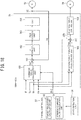
- the EPS-ECU 30 includes a command value calculation unit 31, a subtractor 32, a proportional-integral (PI) control unit 33, a pulse width modulation (PWM) control unit 34, and an inverter (INV) 35.
- PI proportional-integral
- PWM pulse width modulation
- INV inverter
- the command value calculation unit 31 calculates a current command value Iref that is a control target value of a drive current for the steering assistance motor 20 on the basis of a target steering angle ⁇ r set by a travel control ECU 37, the steering angle ⁇ , the steering torque Th, and the vehicle speed Vh.
- the travel control ECU 37 includes a target trajectory calculation unit 38 and a steering command value calculation unit 39.
- the target trajectory calculation unit 38 calculates a target trajectory for causing a vehicle to travel on the basis of a surrounding environment of the vehicle and a traveling state of the vehicle detected by a state detection unit 36.
- the state detection unit 36 may include a distance measuring device and a camera for detecting the surrounding environment of the vehicle and an angular velocity sensor, an acceleration sensor, and the like for detecting the traveling state of the vehicle.
- the steering command value calculation unit 39 calculates the target steering angle ⁇ r that is a control target value of the steering angle ⁇ on the basis of the target trajectory calculated by the target trajectory calculation unit 38 and a result of the detection by the state detection unit 36, and outputs to the EPS-ECU 30.
- the current command value Iref calculated by the command value calculation unit 31 is input to the subtractor 32 in which a deviation (Iref - Im) from a fed-back motor current value Im is calculated.
- the deviation (Iref - Im) is input to the PI control unit 33 for improving characteristics of steering operation.
- a steering assistance command value Vref obtained by the characteristic improvement by the PI control unit 33 is input to the PWM control unit 34, and furthermore, the steering assistance motor 20 is PWM-driven via the inverter 35 as a drive unit.
- the current value Im of the steering assistance motor 20 is detected by the motor current detector 21 and fed back to the subtractor 32.
- the inverter 35 uses a field effect transistor (FET) as a drive element, and is formed by a FET bridge circuit.
- FET field effect transistor
- the command value calculation unit 31 calculates a first assistance control value C1 for controlling the steering assistance motor 20 on the basis of an operation state amount that changes depending on operation by the driver with respect to a steering mechanism.
- the command value calculation unit 31 also calculates a second assistance control value C2 for controlling the steering assistance motor 20 so that the actual steering angle ⁇ approaches the target steering angle ⁇ r.
- the second assistance control value C2 is calculated by PI control based on the deviation ⁇ using the proportionator 45, the integrator 46, and the adder 47.
- the subtractor 41, the proportionator 45, the integrator 46, and the adder 47 are an example of "target value control unit" described in the claims.
- the command value calculation unit 31 further includes an adder 48 that calculates a sum of the first assistance control value C1 and the second assistance control value C2 as the current command value Iref, and calculates the current command value Iref on the basis of at least one of the first assistance control value C1 and the second assistance control value C2.
- the current command value Iref is calculated on the basis of the second assistance control value C2 generated by PI control based on the deviation ⁇ , the current command value Iref in a direction hindering steering of the driver is generated when the deviation ⁇ is generated by steering of the driver, making steering of the driver difficult.
- the command value calculation unit 31 of the first embodiment calculates an integral value of a value corresponding to the operation state amount, and, according to the integral value, suppresses an increase in an integral value of the deviation ⁇ calculated by the integrator 46.
- the integral value of the deviation ⁇ calculated by the integrator 46 is an example of "first integral value” described in the claims
- the integral value of the value corresponding to the operation state amount is an example of "second integral value” described in the claims.
- the integral value of the deviation ⁇ is suppressed according to a duration during which steering holding continues even in a state such as a steering holding state where the operation state amount does not change, so that change in the steering feeling of the driver due to the increased second assistance control value C2 can be suppressed.
- the integral value of the value corresponding to the operation state amount changes more slowly than the operation state amount as is, so that a sudden change in the second assistance control value C2 can be prevented.
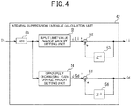
- the command value calculation unit 31 includes an integral suppression variable calculation unit 42, an input limiter 43, and a sign inverter 44.
- the steering torque Th is input to the integral suppression variable calculation unit 42.
- the operation state amount is not limited to the steering torque Th, and, for example, may be the steering angle ⁇ or a turning angle of the steered wheels 8L and 8R.
- the integral suppression variable calculation unit 42 integrates a value that changes according to the steering torque Th to calculate an integral suppression variable for suppressing an increase in the integral value of the deviation ⁇ by the integrator 46.
- the integral suppression variable is an example of "second integral value" described in the claims.
- the integral suppression variable calculation unit 42 calculates an input limit value Li and a gradually decreasing gain Gd as the integral suppression variable.
- the input limit value Li represents an upper limit value and a lower limit value with respect to the deviation ⁇ input to the integrator 46, and limits the magnitude of the deviation ⁇ input to the integrator 46. Therefore, the smaller the input limit value Li, the more suppressed the increase in the integral value, whereas the larger the input limit value Li, the more relaxed the suppression of the increase in the integral value.
- the gradually decreasing gain Gd is a gain that changes a result of integration by the integrator 46 to suppress an increase in the integral value of the deviation ⁇ .
- the gradually decreasing gain Gd may be a gain that is multiplied by the result of integration by the integrator 46.
- the smaller the gradually decreasing gain Gd the more suppressed the increase in the integral value
- the larger the gradually decreasing gain Gd the more relaxed the suppression of the increase in the integral value.
- the integral suppression variable calculation unit 42 includes an absolute value calculation unit (ABS) 50, an input limit value change amount setting unit 51, adders 52 and 55, past value holding units (delay processing units) 53 and 56, and a gradually decreasing gain change amount setting unit 54.
- ABS absolute value calculation unit
- the absolute value calculation unit 50 calculates an absolute value
- the input limit value change amount setting unit 51 sets an input limit value change amount ⁇ Li that changes according to a change in the absolute value
- the input limit value change amount ⁇ Li is an example of "a variable that changes according to an operation state amount" described in the claims.
- the input limit value change amount ⁇ Li is input to the adder 52.
- the adder 52 adds the input limit value Li held in an immediately preceding cycle (one cycle before) through the past value holding unit 53 and the input limit value change amount ⁇ Li to integrate the input limit value change amount ⁇ Li, and calculates a result of the integration as the input limit value Li.
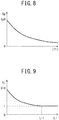
- FIG. 5A illustrates a characteristic example of the input limit value change amount ⁇ Li according to the absolute value
- the input limit value change amount ⁇ Li has a positive value in a range where the absolute value
- the input limit value Li decreases, which further suppresses the increase in the integral value of the deviation ⁇ by the integrator 46.
- the threshold value Th1 may be set to a value larger than a steering torque by which the driver is determined to have no intention of steering (for example, a steering torque applied when simply touching the steering wheel 1). This can prevent the second assistance control value C2 from being excessively suppressed.
- an absolute value of the input limit value change amount ⁇ Li may be set larger as the absolute value
- the input limit value change amount ⁇ Li may be set so that a rate of change in the input limit value change amount ⁇ Li with respect to change in the absolute value
- the input limit value change amount ⁇ Li may be set so that an absolute value of an input limit value change amount L2 set with respect to a steering torque equal to a sum (Th1+ ⁇ ) of the threshold value Th1 and any value ⁇ is larger than an absolute value of an input limit value change amount L1 set with respect to a steering torque equal to a difference (Th1 - ⁇ ) obtained by subtracting the same value ⁇ from the threshold value Th1.
- the area on an origin side from the threshold value Th1 may be set smaller than the other area.
- the input limit value Li can be quickly changed, and the second assistance control value C2 can be adjusted according to the intention of steering.
- change in the input limit value Li can be slowed down when the driver has no (or less) intention of steering and suppression of the increase in the integral value of the deviation ⁇ is relaxed. This can slow down change in the second assistance control value C2 even when the deviation ⁇ is large, so that a sudden change in the steering feeling of the driver can be prevented.
- the gradually decreasing gain change amount setting unit 54 sets a gradually decreasing gain change amount ⁇ Gd that changes according to a change in the absolute value
- the gradually decreasing gain change amount ⁇ Gd is an example of "a variable that changes according to the operation state amount" described in the claims.
- the gradually decreasing gain change amount ⁇ Gd is input to the adder 55.
- the adder 55 adds the gradually decreasing gain Gd held in an immediately preceding cycle (one cycle before) through the past value holding unit 56 and the gradually decreasing gain change amount ⁇ Gd to integrate the gradually decreasing gain change amount ⁇ Gd, and calculates a result of the integration as the gradually decreasing gain Gd.
- FIG. 5B illustrates a characteristic example of the gradually decreasing gain change amount ⁇ Gd according to the absolute value
- the gradually decreasing gain change amount ⁇ Gd has a positive value in a range where the absolute value
- the threshold value Th2 may be the same as or different from the threshold value Th1.
- the gradually decreasing gain change amount ⁇ Gd decreases, which further suppresses the increase in the integral value of the deviation ⁇ by the integrator 46.
- the threshold value Th2 may be set to a value larger than a steering torque by which the driver is determined to have no intention of steering (for example, a steering torque applied when simply touching the steering wheel 1). This can prevent the second assistance control value C2 from being excessively suppressed.
- of the steering torque, the smaller the gradually decreasing gain change amount ⁇ Gd may be set.
- an absolute value of the gradually decreasing gain change amount ⁇ Gd may be set larger as the absolute value
- the gradually decreasing gain change amount ⁇ Gd may be set so that a rate of change in the gradually decreasing gain change amount AGd with respect to change in the absolute value
- the gradually decreasing gain change amount ⁇ Gd may be set so that an absolute value of a gradually decreasing gain change amount G2 set with respect to a steering torque equal to a sum (Th2 + ⁇ ) of the threshold value Th2 and any value ⁇ is larger than an absolute value of a gradually decreasing gain G1 set with respect to a steering torque equal to a difference (Th2 - ⁇ ) obtained by subtracting the same value ⁇ from the threshold value Th2.
- the area on an origin side from the threshold value Th2 may be set smaller than the other area.
- the gradually decreasing gain Gd can be quickly changed, and the second assistance control value C2 can be adjusted according to the intention of steering.
- change in the gradually decreasing gain Gd can be slowed down when the driver has no (or less) intention of steering and suppression of the increase in the integral value of the deviation ⁇ is relaxed.
- This can slow down change in the second assistance control value C2 even when the deviation ⁇ is large, so that a sudden change in the steering feeling of the driver can be prevented.
- the integral suppression variable calculation unit 42 outputs the input limit value Li to the proportionator 45, the input limiter 43, and the sign inverter 44.
- the sign inverter 44 outputs a value (-Li) obtained by inverting a sign of the input limit value Li to the input limiter 43.
- the input limiter 43 inputs a post-limitation deviation ⁇ r obtained by limiting the deviation ⁇ to be input to the integrator 46 according to the input limit values Li and (-Li) to the integrator 46.
- FIG. 6 illustrates an example of input/output characteristics of the input limiter 43.
- the input deviation ⁇ is equal to or more than the lower limit value (-Li) and equal to or less than the upper limit value Li
- the post-limitation deviation ⁇ r is equal to the deviation ⁇ .
- the post-limitation deviation ⁇ r is maintained at the lower limit value (-Li).
- the post-limitation deviation ⁇ r is maintained at the upper limit value Li.
- the absolute value calculation unit 50, the input limit value change amount setting unit 51, the adder 52, the past value holding unit 53, the input limiter 43, and the sign inverter 44 limit the deviation ⁇ integrated in calculation of the integral value of the deviation ⁇ according to the input limit value Li.
- the absolute value calculation unit 50, the input limit value change amount setting unit 51, the adder 52, the past value holding unit 53, the input limiter 43, and the sign inverter 44 are an example of "integral suppression unit" described in the claims.
- the steering torque Th, the deviation ⁇ , and the input limit value Li are input to the proportionator 45.
- the proportionator 45 multiplies a proportional gain Gp corresponding to the steering torque Th by the deviation ⁇ to calculate a proportional component Op of the PI control in the command value calculation unit 31.
- the proportionator 45 changes the proportional component Op according to the input limit value Li. For example, the proportionator 45 increases the proportional component Op as the input limit value Li decreases.
- the proportional component Op increases when the input limit value Li is small and the magnitude of the deviation ⁇ input to the integrator 46 is limited. Accordingly, in a scene where the magnitude of the deviation ⁇ input to the integrator 46 is limited, i.e., in a scene where change in the second assistance control value C2 is suppressed and steering by the driver is prioritized, the proportional component Op is increased, thereby enabling improvement in followability to the target steering angle.
- the proportionator 45 includes an absolute value calculation unit 60 (ABS), a proportional gain setting unit 61, an increase gain setting unit 62, and multipliers 63 and 64.
- the absolute value calculation unit 60 calculates the absolute value
- the proportional gain setting unit 61 calculates the proportional gain Gp according to the absolute value
- the increase gain setting unit 62 calculates an increase gain Gi according to the input limit value Li.
- the multipliers 63 and 64 multiply the proportional gain Gp and the increase gain Gi, respectively, by the deviation ⁇ of the steering angle to calculate the proportional component Op.
- FIG. 8 illustrates a characteristic example of the proportional gain Gp according to the absolute value
- the proportional gain setting unit 61 may set the proportional gain Gp so that the proportional gain Gp is a predetermined value Gp0 when the absolute value
- FIG. 9 illustrates a characteristic example of the increase gain Gi according to the input limit value Li set by the increase gain setting unit 62.
- the increase gain setting unit 62 may set the increase gain Gi so that when the input limit value Li is equal to or more than a threshold value Li1 (when it is relatively large), the increase gain Gi is "1", and when the input limit value Li is below the threshold value Li1 (when it is relatively small), the increase gain Gi is larger than "1” and increases as the input limit value Li decreases.
- the proportional component Op based on the deviation ⁇ is increased according to the input limit value Li, thereby enabling improvement in followability to the target steering angle.
- the increase gain setting unit 62 and the multiplier 64 are an example of "proportional component change unit" described in the claims.
- the increase gain setting unit 62 may set the increase gain Gi on the basis of the gradually decreasing gain Gd instead of the input limit value Li.
- the post-limitation deviation ⁇ r and the gradually decreasing gain Gd are input to the integrator 46.
- the integrator 46 integrates the post-limitation deviation ⁇ r to calculate an integral component Oi of the PI control in the command value calculation unit 31.
- the integrator 46 changes a result of the integration by the integrator 46 according to the gradually decreasing gain Gd to suppress an increase in the integral value of the deviation ⁇ calculated by the integrator 46.
- the integrator 46 includes an integral gain multiplication unit 70, an adder 71, a past value holding unit (delay processing unit) 72, and a multiplier 73.
- the integral gain multiplication unit 70 multiplies the post-limitation deviation ⁇ r by an integral gain Ki.
- the adder 71 adds a product (Ki ⁇ ⁇ r) to the integral component Oi that is an output value of the integrator 46 held in an immediately preceding cycle (one cycle before) through the past value holding unit 72 to calculate an integral value of the product (Ki ⁇ ⁇ r).
- the multiplier 73 multiplies the integral value of the product (Ki ⁇ ⁇ r) output from the adder 71 by the gradually decreasing gain Gd to calculate the integral component Oi.
- the absolute value calculation unit 50, the gradually decreasing gain change amount setting unit 54, the adder 55, the past value holding unit 56, and the multiplier 73 change the result of integration of the deviation ⁇ according to the gradually decreasing gain Gd.
- the absolute value calculation unit 50, the gradually decreasing gain change amount setting unit 54, the adder 55, the past value holding unit 56, and the multiplier 73 are an example of "integral suppression unit" described in the claims.
- the similar effect can be obtained also by adding the gradually decreasing gain Gd as a gradually decreasing change amount according to the steering torque Th to the integral value of the product (Ki ⁇ ⁇ r) between the post-limitation deviation ⁇ r and the integral gain Ki instead of multiplying the gradually decreasing gain Gd by the multiplier 73.
- the multiplier 73 may be arranged in a front stage of the adder 71 instead of arranging it in a rear stage of the adder 71.
- the adder 47 adds the proportional component Op output from the proportionator 45 and the integral component Oi output from the integrator 46 to calculate the second assistance control value C2.
- the adder 48 adds the first assistance control value C1 and the second assistance control value C2 to calculate the current command value Iref, and outputs to the subtractor 32 illustrated in FIG. 2 .
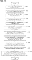
- the first assistance control value calculation unit 40 calculates the first assistance control value C1 on the basis of the steering torque Th and the vehicle speed Vh.
- the travel control ECU 37 calculates the target steering angle ⁇ r that is the control target value of the steering angle ⁇ .
- the steering angle sensor 14 detects the actual steering angle ⁇ .
- the subtractor 41 subtracts the actual steering angle ⁇ from the target steering angle ⁇ r to calculate the deviation ⁇ .
- the integral suppression variable calculation unit 42 calculates the input limit value Li and the gradually decreasing gain Gd.
- the input limiter 43 limits the magnitude of the deviation ⁇ input to the integrator 46 according to the input limit value Li to suppress an increase in the integral value output by the integrator 46.
- the integrator 46 changes the result of integration of the deviation ⁇ r by the integrator 46 according to the gradually decreasing gain Gd to suppress an increase in the integral value output by the integrator 46.
- the proportionator 45 changes the proportional component Op according to the input limit value Li, and increases the proportional component Op as the input limit value Li decreases.
- the adder 47 adds the proportional component Op output from the proportionator 45 and the integral component Oi output from the integrator 46 to calculate the second assistance control value C2.
- the adder 48 adds the first assistance control value C1 and the second assistance control value C2 to calculate the current command value Iref. Then, processing is ended.
- the first assistance control value calculation unit 40 calculates the first assistance control value C1 for controlling the steering assistance motor 20 that turns the steered wheels 8L and 8R.
- the travel control ECU 37 sets the target steering angle ⁇ r as a target value of a state amount indicating a traveling direction of the vehicle on the basis of the surrounding environment of the vehicle.
- the integrator 46 controls the steering assistance motor 20 by integral control according to the integral value of the deviation ⁇ between the actual steering angle ⁇ and the target steering angle ⁇ r.
- the absolute value calculation unit 50, the input limit value change amount setting unit 51, the adders 52 and 55, the past value holding units 53 and 56, and the gradually decreasing gain change amount setting unit 54 calculate the input limit value Li and the gradually decreasing gain Gd as an integral value corresponding to the steering torque Th.
- the input limiter 43, the sign inverter 44, and the multiplier 73 suppress an increase in the integral value of the deviation ⁇ according to the input limit value Li and the gradually decreasing gain Gd.
- an increase in the integral value of the deviation ⁇ is suppressed according to the duration during which steering holding continues even in a state such as the steering holding state where the steering torque Th does not change. This can suppress a change in the steering feeling of the driver due to an increase in the second assistance control value C2.
- the absolute value calculation unit 50, the input limit value change amount setting unit 51, the adders 52 and 55, the past value holding units 53 and 56, and the gradually decreasing gain change amount setting unit 54 may integrate the input limit value change amount ⁇ Li and the gradually decreasing gain change amount ⁇ Gd that change according to the absolute value
- of the steering torque equal to or more than the threshold value Th1 is larger than the rate of change when the absolute value
- of the steering torque equal or more than the threshold value Th2 is larger than the rate of change when the absolute value
- the input limit value Li and the gradually decreasing gain change amount ⁇ Gd can be quickly changed, and the second assistance control value C2 can be adjusted according to the intention of steering.
- the absolute value calculation unit 50, the input limit value change amount setting unit 51, the adder 52, the past value holding unit 53, the input limiter 43, and the sign inverter 44 may limit the deviation ⁇ integrated in the calculation of the integral value of the deviation ⁇ according to the input limit value Li.
- the gradually decreasing gain change amount setting unit 54, the absolute value calculation unit 50, the adder 55, the past value holding unit 56, and the multiplier 73 may change the result of integration of the deviation ⁇ according to the gradually decreasing gain Gd.
- the proportionator 45 controls the steering assistance motor 20 by proportional control according to the proportional component Op of the deviation ⁇ .
- the increase gain setting unit 62 and the multiplier 64 may change the proportional component Op according to the input limit value Li or the gradually decreasing gain Gd.
- the proportional component Op is increased as the input limit value Li decreases, whereby when the input limit value Li is small and the magnitude of the deviation ⁇ input to the integrator 46 is limited, it is possible to increase the proportional component Op.
- the proportional component Op is increased, thereby enabling improvement in followability to the target steering angle.
- the input limit value change amount ⁇ Li is set to a positive value in the range where the absolute value
- the integral suppression variable calculation unit 42 of the first modification determines the driver's intention of steering, and reduces a value of the input limit value change amount ⁇ Li when there is the intention of steering and the input limit value change amount ⁇ Li has a positive value to less than a value of the input limit value change amount ⁇ Li when there is no intention of steering and the input limit value change amount ⁇ Li has a positive value.
- This can suppress an increase in the input limit value Li when the absolute value
- the present modification is also applicable to second and third embodiments and first to third modifications of the third embodiment that will be described below.
- the integral suppression variable calculation unit 42 of the first modification has a functional structure similar to that of the integral suppression variable calculation unit 42 of the first embodiment illustrated in FIG. 4 , and the same reference signs indicate the similar components.
- the integral suppression variable calculation unit 42 of the first modification includes a differentiator 120 and a steering intention determination unit 121.
- the differentiator 120 differentiates the absolute value
- the steering intention determination unit 121 determines the presence or absence of the driver's intention of steering according to the change speed ⁇ . For example, when the change speed ⁇ is equal to or more than a threshold value, it is determined that there is the intention of steering, whereas when the change speed ⁇ is below the threshold value, it is determined that there is no intention of steering.
- the input limit value change amount setting unit 51 sets the input limit value change amount ⁇ Li that changes according to the change in the absolute value
- a solid line 122 indicates characteristics of the input limit value change amount ⁇ Li when there is the driver's intention of steering
- a broken line 123 indicates characteristics of the input limit value change amount ⁇ Li when there is not the driver's intention of steering.
- the input limit value change amount setting unit 51 may set the input limit value change amount ⁇ Li different in characteristics by using a map different depending on the presence or absence of the driver's intention of steering.
- characteristics 122 of the input limit value change amount ⁇ Li where there is the intention of steering may be equal to characteristics 123 of the input limit value change amount ⁇ Li where there is not the intention of steering.
- the input limit value change amount ⁇ Li has a positive value in a range where the absolute value
- the input limit value change amount ⁇ Li (the solid line 122) where there is the intention of steering is reduced to less than the input limit value change amount ⁇ Li (the broken line 123) where there is not the intention of steering.
- the value of the input limit value change amount ⁇ Li when there is the intention of steering and the input limit value change amount ⁇ Li has a positive value can be reduced to less than the value of the input limit value change amount ⁇ Li when there is not the intention of steering and the input limit value change amount ⁇ Li has a positive value.
- the input limit value change amount ⁇ Li may be set to have characteristics between the characteristics 122 and the characteristics 123. This can suppress a sudden change in the integral value due to a change in the input limit value change amount ⁇ Li.
- the integral suppression variable calculation unit 42 of a second modification reduces the input limit value change amount ⁇ Li according to the change speed of the absolute value
- the integral suppression variable calculation unit 42 of the second modification has a functional structure similar to that of the integral suppression variable calculation unit 42 of the first embodiment illustrated in FIG. 4 , and the same reference signs indicate the similar components.
- the integral suppression variable calculation unit 42 of the second modification includes the differentiator 120, a reduction amount setting unit 124, and an adder 125.
- the input limit value change amount setting unit 51 of the second modification sets the input limit value change amount ⁇ Li having the same characteristics as those in the first embodiment.
- the input limit value change amount setting unit 51 of the second modification may set the input limit value change amount ⁇ Li having the characteristics illustrated in FIG. 5A .
- the reduction amount setting unit 124 calculates a reduction amount d ⁇ of the input limit value change amount ⁇ Li according to the change speed ⁇ of the absolute value
- FIG. 13B illustrates a characteristic example of the reduction amount d ⁇ according to the change speed ⁇ of the absolute value
- the reduction amount d ⁇ is zero.
- the reduction amount d ⁇ has a negative value and decreases as the change speed ⁇ increases (in other words, the absolute value of the reduction amount d ⁇ increases).
- the reduction amount d ⁇ maintains a minimum value d ⁇ min.
- the adder 125 adds the reduction amount d ⁇ having the characteristics as in FIG. 13B to the input limit value change amount ⁇ Li, and then the input limit value change amount ⁇ Li after the addition of the reduction amount d ⁇ is reduced by the reduction amount d ⁇ as the change speed ⁇ of the absolute value
- the input limit value change amount ⁇ Li is not reduced, and when the change speed ⁇ is equal to or more than the threshold value ⁇ 2, the input limit value change amount ⁇ Li is reduced by the reduction amount d ⁇ min.
- the input limit value change amount ⁇ Li is reduced by the reduction amount d ⁇ having an absolute value larger as the change speed of the absolute value
- the value of the input limit value change amount ⁇ Li when there is the intention of steering can be reduced to less than the value of the input limit value change amount ⁇ Li when there is not the intention of steering.
- the reduction amount setting unit 124 may determine whether or not the absolute value
- cascade control having a steering angular velocity feedback as a minor loop can improve the responsiveness and stability of a position control loop.
- the command value calculation unit 31 of the second embodiment has a functional structure similar to the first embodiment illustrated in FIG. 3 , and the same reference signs indicate the similar components.
- the command value calculation unit 31 of the second embodiment includes a target steering angular velocity calculation unit 80, an angular velocity calculation unit 81, a subtractor 82, a damping calculation unit 83, and a subtractor 84.
- the subtractors 41 and 82, the target steering angular velocity calculation unit 80, the proportionator 45, the integrator 46, and the adder 47 are an example of "target value control unit" described in the claims.
- the subtractor 41 calculates a difference ⁇ between the target steering angle ⁇ r and the actual steering angle ⁇ .
- the target steering angular velocity calculation unit 80 calculates the target steering angular velocity ⁇ r on the basis of the difference ⁇ between the target steering angle ⁇ r and the actual steering angle ⁇ .
- the angular velocity calculation unit 81 differentiates the actual steering angle ⁇ to calculate the actual steering angular velocity ⁇ .
- the deviation ⁇ is input to the input limiter 43 and the proportionator 45.
- the input limiter 43 outputs a post-limitation deviation ⁇ r obtained by limiting the deviation ⁇ to be input to the integrator 46 according to the input limit values Li and (-Li) .
- the operation of the input limiter 43 of the second embodiment that limits the deviation ⁇ to the post-limitation deviation ⁇ r is the same as the operation of the input limiter 43 of the first embodiment that limits the deviation ⁇ to the post-limitation deviation ⁇ r.
- the proportionator 45 multiplies the proportional gain Gp according to the steering torque Th by the deviation ⁇ to calculate the proportional component Op of the PI control in the command value calculation unit 31.
- the proportionator 45 changes the proportional component Op according to the input limitation value Li.
- the operation of the proportionator 45 of the second embodiment is the same as the operation of the proportionator 45 of the first embodiment except that the proportional gain Gp is multiplied by the deviation ⁇ .
- the integrator 46 integrates the post-limitation deviation ⁇ r to calculate the integral component Oi of the PI control in the command value calculation unit 31.
- the integrator 46 changes the result of integration by the integrator 46 according to the gradually decreasing gain Gd to suppress an increase in an integral value of the deviation ⁇ w calculated by the integrator 46.
- the operation of the integrator 46 of the second embodiment is the same as the operation of the integrator 46 of the first embodiment except that the post-limitation deviation ⁇ r is integrated.
- the damping calculation unit 83 calculates a damping control value D according to the actual steering angular velocity ⁇ .
- the subtractor 84 subtracts the damping control value D from the sum of the first assistance control value C1 and the second assistance control value C2 to calculate the current command value Iref.
- the damping calculation unit 83 may set so that the larger the absolute value
- of the actual steering angular velocity may be set so that the rate of increase is small in regions with small and large absolute values
- step S21 An operation of step S21 is the same as the operation of step S1 in FIG. 11 .
- the target steering angular velocity calculation unit 80 sets the target steering angular velocity ⁇ r on the basis of the difference ⁇ between the target steering angle ⁇ r and the actual steering angle ⁇ .
- the angular velocity calculation unit 81 differentiates the actual steering angle ⁇ to calculate the actual steering angular velocity ⁇ .
- step S25 An operation of step S25 is the same as the operation of step S5 in FIG. 11 .
- the input limiter 43 limits the magnitude of the deviation ⁇ input to the integrator 46 according to the input limit value Li to suppress an increase in an integral value output by the integrator 46.
- the integrator 46 changes a result of integration of the deviation ⁇ r by the integrator 46 according to the gradually decreasing gain Gd to suppress an increase in the integral value output by the integrator 46.
- steps S28 and S29 are the same as those of steps S8 and S9 in FIG. 11 .
- the damping calculation unit 83 calculates a damping control value D according to the actual steering angular velocity ⁇ .
- the adder 48 adds the first assistance control value C1 and the second assistance control value C2.
- the subtractor 84 subtracts the damping control value D from the sum of the first assistance control value C1 and the second assistance control value C2 to calculate the current command value Iref. Then, processing is ended.
- the first assistance control value calculation unit 40 calculates the first assistance control value C1 for controlling the steering assistance motor 20 that turns the steered wheels 8L and 8R on the basis of the steering torque Th and the Vehicle speed Vh.
- the travel control ECU 37 sets the target steering angle ⁇ r as the target value of a state amount indicating the traveling direction of the vehicle on the basis of the surrounding environment of the vehicle.
- the target steering angular velocity calculation unit 80 calculates the target steering angular velocity ⁇ r on the basis of the difference between the actual steering angle ⁇ and the target steering angle ⁇ r.
- the integrator 46 controls the steering assistance motor 20 by integral control according to the integral value of the deviation ⁇ between the actual steering angular velocity ⁇ and the target steering angular velocity ⁇ r.
- the absolute value calculation unit 50, the input limit value change amount setting unit 51, the adders 52 and 55, the past value holding units 53 and 56, and the gradually decreasing gain change amount setting unit 54 calculate the input limit value Li and the gradually decreasing gain Gd as an integral value corresponding to the steering torque Th.
- the input limiter 43, the sign inverter 44, and the multiplier 73 suppress an increase in the integral value of the deviation ⁇ according to the input limit value Li and the gradually decreasing gain Gd.
- cascade control having the steering angular velocity feedback as a minor loop can improve the responsiveness and stability of the position control loop.
- An actuator control device of the third embodiment controls a turning motor that turns steered wheels in a steer-by-wire (SBW) mechanism in which the steering wheel 1 is mechanically separated from the steered wheels 8L and 8R.
- SBW steer-by-wire
- means for turning the turning motor is not limited to the motor, and various kinds of actuators can be used.
- the current command value Iref that is the control target value of a drive current for the turning motor is determined on the basis of the steering angle ⁇ of the steering wheel 1 by the driver and the vehicle speed Vh. Additionally, a current command value of a reaction force motor that applies steering reaction force to the steering wheel 1 is determined according to an actual turning angle ⁇ s of the steered wheels 8L and 8R and the vehicle speed Vh.
- the current command value is added that controls the turning motor so as to cause the actual turning angle to approach a target turning angle set on the basis of the surrounding environment of the vehicle.
- the current command value Iref is calculated by adding a second current command value Iref2 that controls the turning motor so as to cause the actual turning angle to approach a second target turning angle ⁇ r2 set on the basis of the surrounding environment of the vehicle to a first current command value Iref1 based on a first target turning angle ⁇ r1 set by the steering angle ⁇ of the steering wheel 1 by the driver and the vehicle speed Vh.
- the third embodiment can suppress the second current command value Iref2 from changing in a direction opposite to the direction of steering by the driver due to the deviation ⁇ between the first target turning angle ⁇ r1 and the second target turning angle ⁇ r2 caused by the steering by the driver, which can suppress a change in the steering feeling of the driver.
- FIG. 17 illustrates an outline of an example of the steer-by-wire mechanism of the third embodiment.
- the same reference signs are given to the similar components as those of the electric power steering device illustrated in FIG. 1 .
- the steer-by-wire mechanism includes a backup clutch 90, a reaction force motor 91, a turning motor 92, a reduction gear 93, a pinion 94, an SBW-ECU 95, and a turning angle sensor 96.
- the backup clutch 90 mechanically disconnects the steering wheel 1 and the steered wheels 8L and 8R when in a released state, and mechanically connects the steering wheel 1 and the steered wheels 8L and 8R when in an engaged state.
- the reaction force motor 91 that applies a reaction force torque Th to the steering wheel 1 is connected to the steering shaft 2 via the reduction gear 3.
- the turning motor 92 that turns the steered wheels 8L and 8R is connected to the pinion 94 via the reduction gear 93, and the pinion 94 engages with the rack 5b. This converts a rotational motion of the turning motor 92 into a linear motion in the vehicle width direction of the rack 5b.
- the rack 5b is provided with the turning angle sensor 96 that detects an amount of movement of the rack 5b to detect the actual turning angle ⁇ s of the steered wheels 8L and 8R.
- the SBW-ECU 95 calculates a current command value of a turning control command on the basis of the vehicle speed Vh detected by the vehicle speed sensor 12, the steering angle ⁇ detected by the steering angle sensor 14, and the actual turning angle ⁇ s detected by the turning angle sensor 96, and controls a current supplied to the turning motor 92 by a voltage control command value obtained by subjecting the current command value to compensation or the like.
- the SBW-ECU 95 calculates a target reaction force torque on the basis of the vehicle speed Vh detected by the vehicle speed sensor 12 and the actual turning angle ⁇ s detected by the turning angle sensor 96, and performs feedback control for causing the reaction force torque Th detected by the torque sensor 10 to approach the target reaction force torque.
- the SBW-ECU 95 may include, for example, a computer including a processor and peripheral components such as a storage device.
- the processor may be, for example, a CPU or an MPU.
- the storage device may include any of a semiconductor storage device, a magnetic storage device, and an optical storage device.
- the storage device may include memories, such as register, cache memory, and ROM and RAM used as primary storage.
- Functions of the SBW-ECU 95 that will be described below are realized by, for example, causing the processor of the SBW-ECU 95 to execute a computer program stored in the storage device.
- SBW-ECU 95 may be formed by dedicated hardware for executing each information processing that will be described below.
- the SBW-ECU 95 may include a functional logic circuit set in a general-purpose semiconductor integrated circuit.
- the SBW-ECU 95 may include a programmable logic device such as a field-programmable gate array, or the like.
- the SBW-ECU 95 includes a command value calculation unit 100, a subtractor 101, a PI control unit 102, a PWM control unit 103, an inverter 104, a reaction force target value control unit 106, a subtractor 107, and a reaction force control unit 108.
- the command value calculation unit 100 calculates the current command value Iref that is a control target value of a drive current of the turning motor 92 on the basis of the second target turning angle ⁇ r2 set by the travel control ECU 37, the steering angle ⁇ , the vehicle speed Vh, and the actual turning angle ⁇ s.
- the steering command value calculation unit 39 of the travel control ECU 37 calculates the second target turning angle ⁇ r2 that is a control target value of the turning angle ⁇ based on the surrounding environment of the vehicle on the basis of the target trajectory calculated by the target trajectory calculation unit 38 and the detection result by the state detection unit 36, and outputs to the EPS-ECU 30.
- the current command value Iref calculated by the command value calculation unit 100 is input to the subtractor 101, in which a deviation (Iref - Im) from the fed-back motor current value Im is calculated, and the deviation (Iref - Im) is input to the PI control unit 102 for improving characteristics of steering operation.
- a steering assistance command value Vref obtained by the characteristic improvement by the PI control unit 102 is input to the PWM control unit 103, and furthermore, the turning motor 92 is PWM-driven via the inverter 104 as a drive unit.
- the current value Im of the turning motor 92 is detected by a motor current detector 105 and fed back to the subtractor 101.
- the inverter 104 uses a field effect transistor (FET) as a drive element, and is formed by a FET bridge circuit.
- FET field effect transistor
- the reaction force target value control unit 106 sets a target reaction force torque Thr that is a control target value of a steering reaction force torque to be applied to the steering wheel 1.
- the reaction force target value control unit 106 may set the target reaction force torque Thr different depending on whether the steering wheel 1 is turned forth or back.
- the subtractor 107 calculates a deviation ⁇ Th between the reaction force torque Th detected by the torque sensor 10 and the target reaction force torque Thr.
- the reaction force control unit 108 generates a control current for causing the reaction force torque Th to approach the target reaction force torque Thr by feedback control based on the deviation ⁇ Th, and outputs to the reaction force motor 91.
- the command value calculation unit 100 calculates the first current command value Iref1 that controls the turning motor 92 on the basis of the operation state amount that changes according to operation of the steering wheel 1 by the driver and the second current command value Iref2 that controls the turning motor 92 so as to cause the actual turning angle ⁇ s to approach the second target turning angle ⁇ r2 set on the basis of the surrounding environment of the vehicle.
- the command value calculation unit 100 includes a target turning angle calculation unit 110, subtractors 112 and 114, a first current command value calculation unit 113, a second current command value calculation unit 116, and an adder 117.
- the target turning angle calculation unit 110 sets the first target turning angle ⁇ r1 on the basis of the steering angle ⁇ of the steering wheel 1 by the driver and the vehicle speed Vh.
- the subtractor 112 calculates a deviation ( ⁇ r1 - ⁇ s) by subtracting the actual turning angle ⁇ s from the first target turning angle ⁇ r1, and inputs the deviation ( ⁇ r1 - ⁇ s) to the first current command value calculation unit 113.
- the first current command value calculation unit 113 calculates the first current command value Iref1 by feedback control for causing the deviation ( ⁇ r1 - ⁇ s) to approach zero.
- the second current command value calculation unit 116 calculates the second current command value Iref2 by PI control based on the deviation ⁇ .
- the second current command value calculation unit 116 may include an input limiter, a sign inverter, and an integrator that are the similar in structure as the input limiter 43, the sign inverter 44, and the integrator 46 of the first embodiment illustrated in FIG. 3 .
- the second current command value calculation unit 116 calculates an integral value of the deviation ⁇ by the integrator.
- command value calculation unit 100 may include an integral suppression variable calculation unit 115 that is the similar in structure as the integral suppression variable calculation unit 42 of the first embodiment illustrated in FIG. 4 .
- the deviation ⁇ is input to the integral suppression variable calculation unit 115 as the operation state amount by the driver with respect to the steering mechanism.
- the integral suppression variable calculation unit 115 calculates the input limit value Li and the gradually decreasing gain Gd as the integral value of a value corresponding to the deviation ⁇ , and outputs to the second current command value calculation unit 116. Note that the integral suppression variable calculation unit 115 may calculate the input limit value Li and the gradually decreasing gain Gd according to the reaction force torque Th instead of the deviation ⁇ .
- the second current command value calculation unit 116 limits the deviation ⁇ input to the integrator in the calculation of the integral value of the deviation ⁇ according to the input limit value Li, as with the first embodiment.
- the second current command value calculation unit 116 changes a result of integration of the deviation ⁇ according to the gradually decreasing gain Gd.
- the first current command value Iref1 calculated by the first current command value calculation unit 113 and the second current command value Iref2 calculated by the second current command value calculation unit 116 are input to the adder 117.
- the adder 117 adds the first current command value Iref1 and the second current command value Iref2 to calculate the current command value Iref, and inputs to the subtractor 101 illustrated in FIG. 18 .
- the first current command value calculation unit 113 may calculate the first current command value Iref1 by PI control based on the deviation ⁇ .
- the subtractor 112 may calculate a deviation ( ⁇ r2 - ⁇ s) obtained by subtracting the actual turning angle ⁇ s from the second target turning angle ⁇ r2, and the second current command value calculation unit 116 may calculate the second current command value Iref2 by PI control based on the deviation ( ⁇ r2 - ⁇ s).
- the second current command value Iref2 may be calculated by PI control based on an angular velocity deviation between the first target turning angle ⁇ r1 and the second target turning angle ⁇ r2 or an angular velocity deviation between the actual turning angle ⁇ s and the second target turning angle ⁇ r2.
- the input limit value Li and the gradually decreasing gain Gd may be calculated by adopting the actual steering angle ⁇ and the actual steering angular velocity ⁇ as the operation state amount by the driver with respect to the steering mechanism and integrating values that change according to the actual steering angle ⁇ and the actual steering angular velocity ⁇ .
Abstract
Description
- The present invention relates to an actuator control device used in steering of a vehicle.
- An electric power steering device described in
PTL 1 below is known as an automatic steering technology of a vehicle. The electric power steering device includes a damping control unit that proportionally differentiates a steering torque to calculate a correctioncurrent command value 2, a position control unit that receives a steering angle deviation between a target steering angle and an actual steering angle, an integration unit that receives a deviation between a motor speed command value from the position control unit and a motor angular velocity, a proportional unit that receives the motor angular velocity, and a speed control unit that subtracts an output of the proportional unit from an output of the integration unit to output a correctioncurrent command value 1, in which the correctioncurrent command value 1 and the correctioncurrent command value 2 are added to calculate a motor current command value for automatic steering. - Additionally, an actuator control device described in
PTL 2 below includes an assistance control unit that calculates a first assistance component Ta1* and an automatic steering control unit that, while a steering torque is below a threshold value B, calculates a second assistance component Ta2* by PID control using an integral term obtained on the basis of an angle deviation, in which the automatic steering control unit limits the integral term so that the integral term is hard to increase while the steering torque is a threshold value A or above and below the threshold value B as compared with while the steering torque is below A. -
- PTL 1:
JP Pat. No. 5915811 - PTL 2:
JP 2018-024281 A - The electric power steering device of
PTL 1 above generates a control value in a direction opposite to steering of a driver when a steering angle deviation occurs due to the steering of the driver. This can cause a change in a steering feeling of the driver and make the driver feel uncomfortable. - In addition, the actuator control device of
PTL 2 above generates the second assistance component Ta2* by integral control according to the angle deviation when the driver holds the steering wheel with a steering torque equal to or more than the threshold value A and below the threshold value B. Therefore, steering reaction force increasing over time can cause a change in the steering feeling of the driver and make the driver feel uncomfortable. - Additionally, when the driver holds the steering wheel with a steering torque equal to or more than the threshold value B, the second assistance component Ta2* is not generated and there is no discomfort. However, when the steering torque drops below the threshold value B, the angle deviation at the point in time is integrated, so that the second assistance component Ta2* suddenly changes, and sudden steering control may cause the driver to lose control of the steering wheel.
- The present invention has been made in view of the above problems, and it is an object of the present invention to suppress a change in the steering feeling of a driver due to automatic steering control caused by steering operation of the driver.
- To achieve the above object, according to an aspect of the present invention, there is provided an actuator control device for use in steering of a vehicle, the actuator control device including: a turning control value calculation unit configured to calculate a turning control value that controls an actuator configured to turn a steered wheel on a basis of an operation state amount by a driver with respect to a steering mechanism of the vehicle; a target value setting unit configured to set a target value of a state amount indicating a traveling direction of the vehicle on a basis of a surrounding environment of the vehicle; a target value control unit configured to control the actuator by integral control so that actual the state amount approaches the target value; and an integral suppression unit configured to suppress an increase in a first integral value calculated in the integral control according to a second integral value calculated according to the operation state amount.
- For example, the target value control unit may include an integral control unit configured to integrate a deviation between the actual the state amount and the target value to calculate the first integral value, and control the actuator by the integral control according to the first integral value.
- For example, the target value control unit may include a target change speed calculation unit configured to calculate a target change speed of the state amount on a basis of a difference between the actual the state amount and the target value and an integral control unit configured to integrate a deviation between a change speed of the actual the state amount and the target change speed to calculate the first integral value, and control the actuator by the integral control according to the first integral value. Advantageous Effects of Invention
- According to the present invention, it is possible to suppress a change in the steering feeling of a driver due to automatic steering control caused by steering operation of the driver.
-
-
FIG. 1 is a structural diagram illustrating an outline of an example of an electric power steering device of first and second embodiments; -
FIG. 2 is a block diagram illustrating an example of a functional structure of an electric power steering-electronic control unit (EPS-ECU) of the first and second embodiments; -
FIG. 3 is a block diagram illustrating an example of a functional structure of a command value calculation unit of the first embodiment; -
FIG. 4 is a block diagram illustrating an example of a functional structure of an integral suppression variable calculation unit; -
FIG. 5A is a characteristic diagram illustrating an example of characteristics of an input limit value change amount ΔLi according to a steering torque Th, andFIG. 5B is a characteristic diagram illustrating an example of characteristics of a gradually decreasing gain change amount ΔGd according to the steering torque Th; -
FIG. 6 is a characteristic diagram illustrating an example of input/output characteristics of an input limiter; -
FIG. 7 is a block diagram illustrating an example of a functional structure of a proportionator; -
FIG. 8 is a characteristic diagram illustrating an example of characteristics of a proportional gain Gp according to the steering torque Th; -
FIG. 9 is a characteristic diagram illustrating an example of characteristics of an increase gain Gi according to an input limit value Li; -
FIG. 10 is a block diagram illustrating an example of a functional structure of an integrator; -
FIG. 11 is a flowchart illustrating an example of an actuator control method of the first embodiment; -
FIG. 12A is a block diagram illustrating an example of a functional structure of an integral suppression variable calculation unit of a first modification of the first embodiment, andFIG. 12B is a characteristic diagram illustrating an example of characteristics of an input limit value change amount ΔLi of the first modification of the first embodiment; -
FIG. 13A is a block diagram illustrating an example of a functional structure of an integral suppression variable calculation unit of a second modification of the first embodiment, andFIG. 13B is a characteristic diagram illustrating an example of characteristics of a reduction amount dΔ for reducing the input limit value change amount ΔLi; -
FIG. 14 is a block diagram illustrating an example of a functional structure of a command value calculation unit of the second embodiment; -
FIG. 15 is a characteristic diagram illustrating an example of characteristics of a damping control value D according to a steering angular velocity ω; -
FIG. 16 is a flowchart illustrating an example of an actuator control method of the second embodiment; -
FIG. 17 is a block diagram illustrating an example of a functional structure of a structural diagram that illustrates an outline of an example of a steer-by-wire mechanism of a third embodiment; -
FIG. 18 is a block diagram illustrating an example of a functional structure of a steer by wire-electronic control unit(SBW-ECU) of the third embodiment; -
FIG. 19 is a block diagram illustrating an example of a functional structure of a command value calculation unit of the third embodiment; and -
FIG. 20 is a block diagram illustrating an example of a functional structure of a command value calculation unit of a first modification of the third embodiment. Description of Embodiments - Embodiments of the present invention will be described in detail with reference to the drawings.
- It should be noted that the embodiments given below are those exemplifying devices and methods for embodying the technological ideas of the present invention, and the technological ideas of the present invention do not limit the structures, arrangement, and the like of components to those described below. The technological ideas of the present invention can be variously modified within the technological scope defined by the claims described in CLAIMS.
-
FIG. 1 illustrates a structural example of an electric power steering device of first and second embodiments. A steering shaft (steering wheel shaft) 2 of asteering wheel 1 is connected to steeredwheels universal joints pinion rack mechanism 5, andtie rods hub units - The
pinion rack mechanism 5 includes apinion 5a connected to a pinion shaft to which steering force is transmitted from theuniversal joint 4b and arack 5b engaged with thepinion 5a, and converts a rotational motion transmitted to thepinion 5a into a linear motion in a vehicle width direction by therack 5b. - The
steering shaft 2 is provided with atorque sensor 10 that detects a steering torque Th. Additionally, thesteering shaft 2 is provided with asteering angle sensor 14 that detects a steering angle θ of thesteering wheel 1. - Additionally, a
steering assistance motor 20 that assists steering force of thesteering wheel 1 is connected to thesteering shaft 2 via thereduction gear 3. Electric power from abattery 13 is supplied to an electronic control unit (EPS-ECU) 30 that is a controller for controlling the electric power steering (EPS) device, and an ignition key signal is input to the EPS-ECU 30 through an ignition (IGN)key 11. - Note that means for applying the steering assistance force is not limited to the motor, and various kinds of actuators can be used.
- The EPS-
ECU 30 calculates a current command value of an assistance control command on the basis of the steering torque Th detected by thetorque sensor 10, a vehicle speed Vh detected by avehicle sensor 12, and the steering angle θ detected by thesteering angle sensor 14, and controls current supplied to thesteering assistance motor 20 by a voltage control command value Vref obtained by subjecting the calculated current command value to compensation or the like. - Note that the
steering angle sensor 14 is not essential, and the steering angle θ may be acquired from a rotation angle sensor such as a resolver connected to thesteering assistance motor 20. - The EPS-
ECU 30 may include, for example, a computer including a processor and peripheral components such as a storage device. The processor may be, for example, a central processing unit (CPU) or a micro-processing unit (MPU). - The storage device may include any of a semiconductor storage device, a magnetic storage device, and an optical storage device. The storage device may include memories, such as register, cache memory, and read only memory (ROM) and random access memory (RAM) used as primary storage.
- Functions of the EPS-
ECU 30 that will be described below are realized by, for example, causing the processor of the EPS-ECU 30 to execute a computer program stored in the storage device. - Note that the EPS-
ECU 30 may be formed by dedicated hardware for executing each information processing that will be described below. - For example, the EPS-
ECU 30 may include a functional logic circuit set in a general-purpose semiconductor integrated circuit. For example, the EPS-ECU 30 may include a programmable logic device (PLD) such as a field-programmable gate array (FPGA), or the like. - An example of a functional structure of the EPS-
ECU 30 of the first embodiment will be described with reference toFIG. 2 . The EPS-ECU 30 includes a commandvalue calculation unit 31, asubtractor 32, a proportional-integral (PI)control unit 33, a pulse width modulation (PWM)control unit 34, and an inverter (INV) 35. - The command
value calculation unit 31 calculates a current command value Iref that is a control target value of a drive current for thesteering assistance motor 20 on the basis of a target steering angle θr set by atravel control ECU 37, the steering angle θ, the steering torque Th, and the vehicle speed Vh. - The
travel control ECU 37 includes a targettrajectory calculation unit 38 and a steering commandvalue calculation unit 39. The targettrajectory calculation unit 38 calculates a target trajectory for causing a vehicle to travel on the basis of a surrounding environment of the vehicle and a traveling state of the vehicle detected by astate detection unit 36. - The
state detection unit 36 may include a distance measuring device and a camera for detecting the surrounding environment of the vehicle and an angular velocity sensor, an acceleration sensor, and the like for detecting the traveling state of the vehicle. - The steering command
value calculation unit 39 calculates the target steering angle θr that is a control target value of the steering angle θ on the basis of the target trajectory calculated by the targettrajectory calculation unit 38 and a result of the detection by thestate detection unit 36, and outputs to the EPS-ECU 30. - The current command value Iref calculated by the command
value calculation unit 31 is input to thesubtractor 32 in which a deviation (Iref - Im) from a fed-back motor current value Im is calculated. The deviation (Iref - Im) is input to thePI control unit 33 for improving characteristics of steering operation. - A steering assistance command value Vref obtained by the characteristic improvement by the
PI control unit 33 is input to thePWM control unit 34, and furthermore, thesteering assistance motor 20 is PWM-driven via theinverter 35 as a drive unit. The current value Im of thesteering assistance motor 20 is detected by themotor current detector 21 and fed back to thesubtractor 32. Theinverter 35 uses a field effect transistor (FET) as a drive element, and is formed by a FET bridge circuit. - Next, a functional structure of the command
value calculation unit 31 will be described with reference toFIG. 3 . The commandvalue calculation unit 31 calculates a first assistance control value C1 for controlling thesteering assistance motor 20 on the basis of an operation state amount that changes depending on operation by the driver with respect to a steering mechanism. - The command
value calculation unit 31 also calculates a second assistance control value C2 for controlling thesteering assistance motor 20 so that the actual steering angle θ approaches the target steering angle θr. - The command
value calculation unit 31 includes a first assistance controlvalue calculation unit 40 that calculates the first assistant control value C1 on the basis of the steering torque Th and the vehicle speed Vh, asubtractor 41 that calculates a deviation Δθ (= θr - θ) by subtracting the actual steering angle θ from the target steering angle θr, aproportionator 45, anintegrator 46, and anadder 47. The second assistance control value C2 is calculated by PI control based on the deviation Δθ using theproportionator 45, theintegrator 46, and theadder 47. Thesubtractor 41, theproportionator 45, theintegrator 46, and theadder 47 are an example of "target value control unit" described in the claims. - The command
value calculation unit 31 further includes anadder 48 that calculates a sum of the first assistance control value C1 and the second assistance control value C2 as the current command value Iref, and calculates the current command value Iref on the basis of at least one of the first assistance control value C1 and the second assistance control value C2. - If the current command value Iref is calculated on the basis of the second assistance control value C2 generated by PI control based on the deviation Δθ, the current command value Iref in a direction hindering steering of the driver is generated when the deviation Δθ is generated by steering of the driver, making steering of the driver difficult.
- In addition, if the deviation Δθ is maintained by the holding of the steering wheel by the driver, continuous integration of the deviation Δθ increases the second assistance control value C2, and steering reaction force increases over time, which creates a discomfort.
- These problems can be solved by stopping the integration of the deviation Δθ depending on a magnitude of the operation state amount (for example, the steering torque Th) as is by the driver with respect to the steering mechanism.
- However, when after stopping the integration due to an increased operation state amount, the operation state amount decreases and the integration stop is lifted, the deviation Δθ at the point in time is integrated, so that the second assistance control value C2 may suddenly change, and sudden steering control may cause the driver to lose control of the steering wheel.
- Thus, the command
value calculation unit 31 of the first embodiment calculates an integral value of a value corresponding to the operation state amount, and, according to the integral value, suppresses an increase in an integral value of the deviation Δθ calculated by theintegrator 46. Note that the integral value of the deviation Δθ calculated by theintegrator 46 is an example of "first integral value" described in the claims, and the integral value of the value corresponding to the operation state amount is an example of "second integral value" described in the claims. - By suppressing the increase in the integral value of the deviation Δθ according to the integral value of the value corresponding to the operation state amount, a change in the second assistance control value C2 in a direction opposite to a direction of steering by the driver is suppressed when the operation state amount by the driver is large and the driver has a strong intention of steering, thus enabling suppression of a change in the steering feeling of the driver.
- Additionally, by suppressing according to the integral value of the value corresponding to the operation state amount instead of the operation state amount as is, the integral value of the deviation Δθ is suppressed according to a duration during which steering holding continues even in a state such as a steering holding state where the operation state amount does not change, so that change in the steering feeling of the driver due to the increased second assistance control value C2 can be suppressed.
- In addition, even when lifting the suppression of the increase in the first integral value due to a decrease in the operation state amount, the integral value of the value corresponding to the operation state amount changes more slowly than the operation state amount as is, so that a sudden change in the second assistance control value C2 can be prevented.
- The command
value calculation unit 31 includes an integral suppressionvariable calculation unit 42, aninput limiter 43, and asign inverter 44. As an example of the operation state amount by the driver with respect to the steering mechanism, the steering torque Th is input to the integral suppressionvariable calculation unit 42. Note that the operation state amount is not limited to the steering torque Th, and, for example, may be the steering angle θ or a turning angle of the steeredwheels - The integral suppression
variable calculation unit 42 integrates a value that changes according to the steering torque Th to calculate an integral suppression variable for suppressing an increase in the integral value of the deviation Δθ by theintegrator 46. - The integral suppression variable is an example of "second integral value" described in the claims. The integral suppression
variable calculation unit 42 calculates an input limit value Li and a gradually decreasing gain Gd as the integral suppression variable. - The input limit value Li represents an upper limit value and a lower limit value with respect to the deviation Δθ input to the
integrator 46, and limits the magnitude of the deviation Δθ input to theintegrator 46. Therefore, the smaller the input limit value Li, the more suppressed the increase in the integral value, whereas the larger the input limit value Li, the more relaxed the suppression of the increase in the integral value. - The gradually decreasing gain Gd is a gain that changes a result of integration by the
integrator 46 to suppress an increase in the integral value of the deviation Δθ. For example, the gradually decreasing gain Gd may be a gain that is multiplied by the result of integration by theintegrator 46. In this case, the smaller the gradually decreasing gain Gd, the more suppressed the increase in the integral value, whereas the larger the gradually decreasing gain Gd, the more relaxed the suppression of the increase in the integral value. - Reference will be made to
FIG. 4 . The integral suppressionvariable calculation unit 42 includes an absolute value calculation unit (ABS) 50, an input limit value changeamount setting unit 51,adders amount setting unit 54. - The absolute
value calculation unit 50 calculates an absolute value |Th| of the steering torque Th and inputs to the input limit value changeamount setting unit 51 and the gradually decreasing gain changeamount setting unit 54. - The input limit value change
amount setting unit 51 sets an input limit value change amount ΔLi that changes according to a change in the absolute value |Th| of the steering torque. The input limit value change amount ΔLi is an example of "a variable that changes according to an operation state amount" described in the claims. - The input limit value change amount ΔLi is input to the
adder 52. Theadder 52 adds the input limit value Li held in an immediately preceding cycle (one cycle before) through the pastvalue holding unit 53 and the input limit value change amount ΔLi to integrate the input limit value change amount ΔLi, and calculates a result of the integration as the input limit value Li. -
FIG. 5A illustrates a characteristic example of the input limit value change amount ΔLi according to the absolute value |Th| of the steering torque set by the input limit value changeamount setting unit 51. - The input limit value change amount ΔLi has a positive value in a range where the absolute value |Th| of the steering torque is below a threshold value Th1, whereas it has a negative value in a range where the absolute value |Th| thereof is equal to or more than the threshold value Th1.
- As a result, when the absolute value |Th| of the steering torque is below the threshold value Th1 (when the |Th| is relatively small), the input limit value Li increases, which relaxes suppression of the increase in the integral value of the deviation Δθ by the
integrator 46. - Additionally, when the absolute value |Th| of the steering torque is equal to or more than the threshold value Th1 (when the |Th| is relatively large), the input limit value Li decreases, which further suppresses the increase in the integral value of the deviation Δθ by the
integrator 46. - The threshold value Th1 may be set to a value larger than a steering torque by which the driver is determined to have no intention of steering (for example, a steering torque applied when simply touching the steering wheel 1). This can prevent the second assistance control value C2 from being excessively suppressed.
- The larger the absolute value |Th| of the steering torque, the smaller the input limit value change amount ΔLi may be set. For example, in a range where the absolute value |Th| of the steering torque is equal to or more than the threshold value Th1 and the input limit value change amount ΔLi has a negative value, an absolute value of the input limit value change amount ΔLi may be set larger as the absolute value |Th| of the steering torque is larger. As a result, the input limit value Li can be quickly changed when the driver has a strong intention of steering, and the second assistance control value C2 can be adjusted according to the intention of steering.
- Furthermore, the input limit value change amount ΔLi may be set so that a rate of change in the input limit value change amount ΔLi with respect to change in the absolute value |Th| of the steering torque equal or more than the threshold value Th1 is larger than the rate of change when the absolute value |Th| is below the threshold value Th1.
- For example, the input limit value change amount ΔLi may be set so that an absolute value of an input limit value change amount L2 set with respect to a steering torque equal to a sum (Th1+ Δ) of the threshold value Th1 and any value Δ is larger than an absolute value of an input limit value change amount L1 set with respect to a steering torque equal to a difference (Th1 - Δ) obtained by subtracting the same value Δ from the threshold value Th1. Additionally, when comparing two areas set by an axis representing the absolute value of the steering torque, the threshold value Th1, and a characteristic line of the input limit value change amount ΔLi, the area on an origin side from the threshold value Th1 may be set smaller than the other area.
- As a result, when the driver has a strong intention of steering, the input limit value Li can be quickly changed, and the second assistance control value C2 can be adjusted according to the intention of steering.
- On the other hand, change in the input limit value Li can be slowed down when the driver has no (or less) intention of steering and suppression of the increase in the integral value of the deviation Δθ is relaxed. This can slow down change in the second assistance control value C2 even when the deviation Δθ is large, so that a sudden change in the steering feeling of the driver can be prevented.
- Reference will be made to
FIG. 4 . The gradually decreasing gain changeamount setting unit 54 sets a gradually decreasing gain change amount ΔGd that changes according to a change in the absolute value |Th| of the steering torque. The gradually decreasing gain change amount ΔGd is an example of "a variable that changes according to the operation state amount" described in the claims. - The gradually decreasing gain change amount ΔGd is input to the
adder 55. Theadder 55 adds the gradually decreasing gain Gd held in an immediately preceding cycle (one cycle before) through the pastvalue holding unit 56 and the gradually decreasing gain change amount ΔGd to integrate the gradually decreasing gain change amount ΔGd, and calculates a result of the integration as the gradually decreasing gain Gd. -
FIG. 5B illustrates a characteristic example of the gradually decreasing gain change amount ΔGd according to the absolute value |Th| of the steering torque set by the gradually decreasing gain changeamount setting unit 54. - The gradually decreasing gain change amount ΔGd has a positive value in a range where the absolute value |Th| of the steering torque is below a threshold value Th2, whereas it has a negative value in a range where the absolute value |Th| thereof is equal to or more than the threshold value Th2.
- As a result, when the absolute value |Th| of the steering torque is below the threshold value Th2 (when the |Th| is relatively small), the gradually decreasing gain change amount ΔGd increases, which relaxes suppression of the increase in the integral value of the deviation Δθ by the
integrator 46. The threshold value Th2 may be the same as or different from the threshold value Th1. - Additionally, when the absolute value |Th| of the steering torque is equal to or more than the threshold value Th2 (when the |Th| is relatively large), the gradually decreasing gain change amount ΔGd decreases, which further suppresses the increase in the integral value of the deviation Δθ by the
integrator 46. - The threshold value Th2 may be set to a value larger than a steering torque by which the driver is determined to have no intention of steering (for example, a steering torque applied when simply touching the steering wheel 1). This can prevent the second assistance control value C2 from being excessively suppressed.
- The larger the absolute value |Th| of the steering torque, the smaller the gradually decreasing gain change amount ΔGd may be set. For example, in a range where the absolute value |Th| of the steering torque is equal to or more than the threshold value Th2 and the gradually decreasing gain change amount ΔGd has a negative value, an absolute value of the gradually decreasing gain change amount ΔGd may be set larger as the absolute value |Th| of the steering torque is larger. As a result, when the driver has a strong intention of steering, the gradually decreasing gain Gd can be quickly changed, and the second assistance control value C2 can be adjusted according to the intention of steering.
- Furthermore, the gradually decreasing gain change amount ΔGd may be set so that a rate of change in the gradually decreasing gain change amount AGd with respect to change in the absolute value |Th| of the steering torque equal or more than the threshold value Th2 is larger than the rate of change when the absolute value |Th| is below the threshold value Th2.
- For example, the gradually decreasing gain change amount ΔGd may be set so that an absolute value of a gradually decreasing gain change amount G2 set with respect to a steering torque equal to a sum (Th2 + Δ) of the threshold value Th2 and any value Δ is larger than an absolute value of a gradually decreasing gain G1 set with respect to a steering torque equal to a difference (Th2 - Δ) obtained by subtracting the same value Δ from the threshold value Th2. Additionally, when comparing two areas set by an axis representing the absolute value of the steering torque, the threshold value Th2, and a characteristic line of the gradually decreasing gain change amount ΔGd, the area on an origin side from the threshold value Th2 may be set smaller than the other area.
- As a result, when the driver has a strong intention of steering, the gradually decreasing gain Gd can be quickly changed, and the second assistance control value C2 can be adjusted according to the intention of steering.
- On the other hand, change in the gradually decreasing gain Gd can be slowed down when the driver has no (or less) intention of steering and suppression of the increase in the integral value of the deviation Δθ is relaxed. This can slow down change in the second assistance control value C2 even when the deviation Δθ is large, so that a sudden change in the steering feeling of the driver can be prevented.
- Reference will be made to
FIG. 3 . The integral suppressionvariable calculation unit 42 outputs the input limit value Li to theproportionator 45, theinput limiter 43, and thesign inverter 44. Thesign inverter 44 outputs a value (-Li) obtained by inverting a sign of the input limit value Li to theinput limiter 43. - The
input limiter 43 inputs a post-limitation deviation Δθr obtained by limiting the deviation Δθ to be input to theintegrator 46 according to the input limit values Li and (-Li) to theintegrator 46. -
FIG. 6 illustrates an example of input/output characteristics of theinput limiter 43. When the input deviation Δθ is equal to or more than the lower limit value (-Li) and equal to or less than the upper limit value Li, the post-limitation deviation Δθr is equal to the deviation Δθ. - When the deviation Δθ is below the lower limit value (-Li), the post-limitation deviation Δθr is maintained at the lower limit value (-Li). When the deviation Δθ is more than the upper limit value Li, the post-limitation deviation Δθr is maintained at the upper limit value Li.
- In this way, the absolute
value calculation unit 50, the input limit value changeamount setting unit 51, theadder 52, the pastvalue holding unit 53, theinput limiter 43, and thesign inverter 44 limit the deviation Δθ integrated in calculation of the integral value of the deviation Δθ according to the input limit value Li. - The absolute
value calculation unit 50, the input limit value changeamount setting unit 51, theadder 52, the pastvalue holding unit 53, theinput limiter 43, and thesign inverter 44 are an example of "integral suppression unit" described in the claims. - Reference will be made to
FIG. 3 . The steering torque Th, the deviation Δθ, and the input limit value Li are input to theproportionator 45. Theproportionator 45 multiplies a proportional gain Gp corresponding to the steering torque Th by the deviation Δθ to calculate a proportional component Op of the PI control in the commandvalue calculation unit 31. - Additionally, the proportionator 45 changes the proportional component Op according to the input limit value Li. For example, the
proportionator 45 increases the proportional component Op as the input limit value Li decreases. - As a result, the proportional component Op increases when the input limit value Li is small and the magnitude of the deviation Δθ input to the
integrator 46 is limited. Accordingly, in a scene where the magnitude of the deviation Δθ input to theintegrator 46 is limited, i.e., in a scene where change in the second assistance control value C2 is suppressed and steering by the driver is prioritized, the proportional component Op is increased, thereby enabling improvement in followability to the target steering angle. - Reference will be made to
FIG. 7 . Theproportionator 45 includes an absolute value calculation unit 60 (ABS), a proportionalgain setting unit 61, an increasegain setting unit 62, andmultipliers - The absolute
value calculation unit 60 calculates the absolute value |Th| of the steering torque Th and inputs to the proportionalgain setting unit 61. The proportionalgain setting unit 61 calculates the proportional gain Gp according to the absolute value |Th| of the steering torque. - In addition, the increase
gain setting unit 62 calculates an increase gain Gi according to the input limit value Li. Themultipliers -
FIG. 8 illustrates a characteristic example of the proportional gain Gp according to the absolute value |Th| of the steering torque set by the proportionalgain setting unit 61. The proportionalgain setting unit 61 may set the proportional gain Gp so that the proportional gain Gp is a predetermined value Gp0 when the absolute value |Th| of the steering torque is zero, and the proportional gain Gp decreases as the |Th| increases. - As a result, when the steering torque Th is large, the driver's intention of steering is determined to be strong, so that even when the deviation Δθ is generated by steering, a change in the proportional component Op output by the
proportionator 45 can be suppressed. By doing this, the change in the second assistance control value C2 is suppressed, and steering by the driver is prioritized. -
FIG. 9 illustrates a characteristic example of the increase gain Gi according to the input limit value Li set by the increasegain setting unit 62. - The increase
gain setting unit 62 may set the increase gain Gi so that when the input limit value Li is equal to or more than a threshold value Li1 (when it is relatively large), the increase gain Gi is "1", and when the input limit value Li is below the threshold value Li1 (when it is relatively small), the increase gain Gi is larger than "1" and increases as the input limit value Li decreases. - As a result, in the scene where the magnitude of the deviation Δθ input to the
integrator 46 is limited (i.e., the scene where the change in the second assistance control value C2 is suppressed and steering by the driver is prioritized), the proportional component Op based on the deviation Δθ is increased according to the input limit value Li, thereby enabling improvement in followability to the target steering angle. - The increase
gain setting unit 62 and themultiplier 64 are an example of "proportional component change unit" described in the claims. - Note that the increase
gain setting unit 62 may set the increase gain Gi on the basis of the gradually decreasing gain Gd instead of the input limit value Li. - Reference will be made to
FIG. 3 . The post-limitation deviation Δθr and the gradually decreasing gain Gd are input to theintegrator 46. Theintegrator 46 integrates the post-limitation deviation Δθr to calculate an integral component Oi of the PI control in the commandvalue calculation unit 31. - In addition, the
integrator 46 changes a result of the integration by theintegrator 46 according to the gradually decreasing gain Gd to suppress an increase in the integral value of the deviation Δθ calculated by theintegrator 46. - Reference will be made to
FIG. 10 . Theintegrator 46 includes an integralgain multiplication unit 70, anadder 71, a past value holding unit (delay processing unit) 72, and amultiplier 73. - The integral
gain multiplication unit 70 multiplies the post-limitation deviation Δθr by an integral gain Ki. Theadder 71 adds a product (Ki × Δθr) to the integral component Oi that is an output value of theintegrator 46 held in an immediately preceding cycle (one cycle before) through the pastvalue holding unit 72 to calculate an integral value of the product (Ki × Δθr). - The
multiplier 73 multiplies the integral value of the product (Ki × Δθr) output from theadder 71 by the gradually decreasing gain Gd to calculate the integral component Oi. - In this way, the absolute
value calculation unit 50, the gradually decreasing gain changeamount setting unit 54, theadder 55, the pastvalue holding unit 56, and themultiplier 73 change the result of integration of the deviation Δθ according to the gradually decreasing gain Gd. - The absolute
value calculation unit 50, the gradually decreasing gain changeamount setting unit 54, theadder 55, the pastvalue holding unit 56, and themultiplier 73 are an example of "integral suppression unit" described in the claims. - Note that the similar effect can be obtained also by adding the gradually decreasing gain Gd as a gradually decreasing change amount according to the steering torque Th to the integral value of the product (Ki × Δθr) between the post-limitation deviation Δθr and the integral gain Ki instead of multiplying the gradually decreasing gain Gd by the
multiplier 73. Additionally, themultiplier 73 may be arranged in a front stage of theadder 71 instead of arranging it in a rear stage of theadder 71. - Reference will be made to
FIG. 3 . Theadder 47 adds the proportional component Op output from theproportionator 45 and the integral component Oi output from theintegrator 46 to calculate the second assistance control value C2. - The
adder 48 adds the first assistance control value C1 and the second assistance control value C2 to calculate the current command value Iref, and outputs to thesubtractor 32 illustrated inFIG. 2 . - Next, an example of an actuator control method of the first embodiment will be described with reference to
FIG. 11 . - At step S1, the first assistance control
value calculation unit 40 calculates the first assistance control value C1 on the basis of the steering torque Th and the vehicle speed Vh. - At step S2, the
travel control ECU 37 calculates the target steering angle θr that is the control target value of the steering angle θ. - At step S3, the
steering angle sensor 14 detects the actual steering angle θ. - At step S4, the
subtractor 41 subtracts the actual steering angle θ from the target steering angle θr to calculate the deviation Δθ. - At step S5, the integral suppression
variable calculation unit 42 calculates the input limit value Li and the gradually decreasing gain Gd. - At step S6, the
input limiter 43 limits the magnitude of the deviation Δθ input to theintegrator 46 according to the input limit value Li to suppress an increase in the integral value output by theintegrator 46. - At step S7, the
integrator 46 changes the result of integration of the deviation Δθr by theintegrator 46 according to the gradually decreasing gain Gd to suppress an increase in the integral value output by theintegrator 46. - At step S8, the proportionator 45 changes the proportional component Op according to the input limit value Li, and increases the proportional component Op as the input limit value Li decreases.
- At step S9, the
adder 47 adds the proportional component Op output from theproportionator 45 and the integral component Oi output from theintegrator 46 to calculate the second assistance control value C2. - At step S10, the
adder 48 adds the first assistance control value C1 and the second assistance control value C2 to calculate the current command value Iref. Then, processing is ended. - (1) On the basis of the steering torque Th and the vehicle speed Vh, the first assistance control
value calculation unit 40 calculates the first assistance control value C1 for controlling thesteering assistance motor 20 that turns the steeredwheels travel control ECU 37 sets the target steering angle θr as a target value of a state amount indicating a traveling direction of the vehicle on the basis of the surrounding environment of the vehicle. Theintegrator 46 controls thesteering assistance motor 20 by integral control according to the integral value of the deviation Δθ between the actual steering angle θ and the target steering angle θr. - The absolute
value calculation unit 50, the input limit value changeamount setting unit 51, theadders value holding units amount setting unit 54 calculate the input limit value Li and the gradually decreasing gain Gd as an integral value corresponding to the steering torque Th. Theinput limiter 43, thesign inverter 44, and themultiplier 73 suppress an increase in the integral value of the deviation Δθ according to the input limit value Li and the gradually decreasing gain Gd. - As a result, when the steering torque Th is large and the driver has a strong intention of steering, it is possible to suppress the second assistance control value C2 from changing in a direction opposite to the direction of steering by the driver due to the deviation Δθ caused by steering operation by the driver. Thus, a change in the steering feeling of the driver can be suppressed.
- Additionally, by suppressing according to the integral value of the value corresponding to the steering torque Th instead of the steering torque Th, an increase in the integral value of the deviation Δθ is suppressed according to the duration during which steering holding continues even in a state such as the steering holding state where the steering torque Th does not change. This can suppress a change in the steering feeling of the driver due to an increase in the second assistance control value C2.
- Furthermore, even when the steering torque Th decreases and suppression of the increase in the integral value of the deviation Δθ is relaxed, a sudden change in the second assistance control value C2 can be prevented since the integral value of the value corresponding to the steering torque Th changes more slowly than the steering torque Th as is.
- (2) The absolute
value calculation unit 50, the input limit value changeamount setting unit 51, theadders value holding units amount setting unit 54 may integrate the input limit value change amount ΔLi and the gradually decreasing gain change amount ΔGd that change according to the absolute value |Th| of the steering torque to calculate the input limit value Li and the gradually decreasing gain Gd, respectively. The rate of change in the input limit value change amount ΔLi with respect to change in the absolute value |Th| of the steering torque equal to or more than the threshold value Th1 is larger than the rate of change when the absolute value |Th| is below the threshold value Th1. Additionally, the rate of change in the gradually decreasing gain change amount ΔGd with respect to change in the absolute value |Th| of the steering torque equal or more than the threshold value Th2 is larger than the rate of change when the absolute value |Th| is below the threshold value Th2. - As a result, when the driver has a strong intention of steering, the input limit value Li and the gradually decreasing gain change amount ΔGd can be quickly changed, and the second assistance control value C2 can be adjusted according to the intention of steering.
- On the other hand, when the driver has no (or less) intention of steering and suppression of the increase in the integral value of the deviation Δθ is relaxed, changes in the input limit value Li and the gradually decreasing gain change amount ΔGd can be slowed down. This can slow down change in the second assistance control value C2 even when the deviation Δθ is large, so that a sudden change in the steering feeling of the driver can be prevented.
- (3) The absolute
value calculation unit 50, the input limit value changeamount setting unit 51, theadder 52, the pastvalue holding unit 53, theinput limiter 43, and thesign inverter 44 may limit the deviation Δθ integrated in the calculation of the integral value of the deviation Δθ according to the input limit value Li. - The gradually decreasing gain change
amount setting unit 54, the absolutevalue calculation unit 50, theadder 55, the pastvalue holding unit 56, and themultiplier 73 may change the result of integration of the deviation Δθ according to the gradually decreasing gain Gd. - This can suppress an increase in the integral value of the deviation Δθ according to the input limit value Li and the gradually decreasing gain Gd.
- (4) The
proportionator 45 controls thesteering assistance motor 20 by proportional control according to the proportional component Op of the deviation Δθ. The increasegain setting unit 62 and themultiplier 64 may change the proportional component Op according to the input limit value Li or the gradually decreasing gain Gd. - Thus, for example, the proportional component Op is increased as the input limit value Li decreases, whereby when the input limit value Li is small and the magnitude of the deviation Δθ input to the
integrator 46 is limited, it is possible to increase the proportional component Op. As a result, in the scene where the magnitude of the deviation Δθ input to theintegrator 46 is limited, i.e., in the scene where change in the second assistance control value C2 is suppressed and steering by the driver is prioritized, the proportional component Op is increased, thereby enabling improvement in followability to the target steering angle. - Reference will be made to
FIG. 5A . The input limit value change amount ΔLi is set to a positive value in the range where the absolute value |Th| of the steering torque is relatively small (specifically, the |Th| is below the threshold value Th1), and the smaller the absolute value |Th| of the steering torque, the larger the input limit value change amount ΔLi. Therefore, when the driver steers the wheel so as to cause the actual steering angle θ to approach the target steering angle θr and the absolute value |Th| of the steering torque decreases, the input limit value Li increases, which makes it impossible to suppress integration of the integral component Oi output by theintegrator 46. This results in increased steering reaction force despite the driver's intention of steering. - Thus, the integral suppression
variable calculation unit 42 of the first modification determines the driver's intention of steering, and reduces a value of the input limit value change amount ΔLi when there is the intention of steering and the input limit value change amount ΔLi has a positive value to less than a value of the input limit value change amount ΔLi when there is no intention of steering and the input limit value change amount ΔLi has a positive value. This can suppress an increase in the input limit value Li when the absolute value |Th| of the steering torque decreases despite the driver's intention of steering. Note that the present modification is also applicable to second and third embodiments and first to third modifications of the third embodiment that will be described below. - Reference will be made to
FIG. 12A . The integral suppressionvariable calculation unit 42 of the first modification has a functional structure similar to that of the integral suppressionvariable calculation unit 42 of the first embodiment illustrated inFIG. 4 , and the same reference signs indicate the similar components. - The integral suppression
variable calculation unit 42 of the first modification includes adifferentiator 120 and a steering intention determination unit 121. - The
differentiator 120 differentiates the absolute value |Th| of the steering torque to calculate a change speed τ of the absolute value |Th| of the steering torque. - The steering intention determination unit 121 determines the presence or absence of the driver's intention of steering according to the change speed τ. For example, when the change speed τ is equal to or more than a threshold value, it is determined that there is the intention of steering, whereas when the change speed τ is below the threshold value, it is determined that there is no intention of steering.
- The input limit value change
amount setting unit 51 sets the input limit value change amount ΔLi that changes according to the change in the absolute value |Th| of the steering torque. In this case, the input limit value changeamount setting unit 51 sets the input limit value change amount ΔLi different in characteristics depending on the presence or absence of the driver's intention of steering. - Reference will be made to
FIG. 12B . Asolid line 122 indicates characteristics of the input limit value change amount ΔLi when there is the driver's intention of steering, and abroken line 123 indicates characteristics of the input limit value change amount ΔLi when there is not the driver's intention of steering. For example, the input limit value changeamount setting unit 51 may set the input limit value change amount ΔLi different in characteristics by using a map different depending on the presence or absence of the driver's intention of steering. - As illustrated, when the input limit value change amount ΔLi has a negative value in a range where the absolute value |Th| of the steering torque is relatively large (specifically, a range where the |Th| is equal to or more than the threshold value Th1),
characteristics 122 of the input limit value change amount ΔLi where there is the intention of steering may be equal tocharacteristics 123 of the input limit value change amount ΔLi where there is not the intention of steering. - On the other hand, when the input limit value change amount ΔLi has a positive value in a range where the absolute value |Th| of the steering torque is relatively small (specifically, a range where the |Th| is below the threshold value Th1), the input limit value change amount ΔLi (the solid line 122) where there is the intention of steering is reduced to less than the input limit value change amount ΔLi (the broken line 123) where there is not the intention of steering.
- With such a structure, the value of the input limit value change amount ΔLi when there is the intention of steering and the input limit value change amount ΔLi has a positive value can be reduced to less than the value of the input limit value change amount ΔLi when there is not the intention of steering and the input limit value change amount ΔLi has a positive value.
- Additionally, when the change speed τ is in a range below the threshold value, the input limit value change amount ΔLi may be set to have characteristics between the
characteristics 122 and thecharacteristics 123. This can suppress a sudden change in the integral value due to a change in the input limit value change amount ΔLi. - The integral suppression
variable calculation unit 42 of a second modification reduces the input limit value change amount ΔLi according to the change speed of the absolute value |Th| of the steering torque. Even when the input limit value change amount ΔLi is reduced in this way, it is possible to suppress an increase in the input limit value Li when the absolute value |Th| of the steering torque decreases despite the driver's intention of steering, as with the above first modification. Note that the present modification is also applicable to the second embodiment and the third embodiment and the first to third modifications of the third embodiment that will be described below. - Reference will be made to
FIG. 13A . The integral suppressionvariable calculation unit 42 of the second modification has a functional structure similar to that of the integral suppressionvariable calculation unit 42 of the first embodiment illustrated inFIG. 4 , and the same reference signs indicate the similar components. - The integral suppression
variable calculation unit 42 of the second modification includes thedifferentiator 120, a reduction amount setting unit 124, and anadder 125. - The input limit value change
amount setting unit 51 of the second modification sets the input limit value change amount ΔLi having the same characteristics as those in the first embodiment. For example, the input limit value changeamount setting unit 51 of the second modification may set the input limit value change amount ΔLi having the characteristics illustrated inFIG. 5A . - The reduction amount setting unit 124 calculates a reduction amount dΔ of the input limit value change amount ΔLi according to the change speed τ of the absolute value |Th| of the steering torque.
-
FIG. 13B illustrates a characteristic example of the reduction amount dΔ according to the change speed τ of the absolute value |Th| of the steering torque. - When the change speed τ is relatively small (specifically, when the change speed τ is below a threshold value τ1), the reduction amount dΔ is zero.
- On the other hand, when the change speed τ is equal to or more than the threshold value τ1 and below a threshold value τ2, the reduction amount dΔ has a negative value and decreases as the change speed τ increases (in other words, the absolute value of the reduction amount dΔ increases).
- When the change speed τ is equal to or more than the threshold value τ2, the reduction amount dΔ maintains a minimum value dΔmin.
- Reference will be made to
FIG. 13A . Theadder 125 adds the reduction amount dΔ having the characteristics as inFIG. 13B to the input limit value change amount ΔLi, and then the input limit value change amount ΔLi after the addition of the reduction amount dΔ is reduced by the reduction amount dΔ as the change speed τ of the absolute value |Th| of the steering torque increases. - Specifically, when the change speed τ is below the threshold value τ1, the input limit value change amount ΔLi is not reduced, and when the change speed τ is equal to or more than the threshold value τ2, the input limit value change amount ΔLi is reduced by the reduction amount dΔmin.
- In addition, when the change speed τ is equal to or more than the threshold value τ1 and below the threshold value τ2, the input limit value change amount ΔLi is reduced by the reduction amount dΔ having an absolute value larger as the change speed of the absolute value |Th| of the steering torque increases.
- Even with such a structure, the value of the input limit value change amount ΔLi when there is the intention of steering can be reduced to less than the value of the input limit value change amount ΔLi when there is not the intention of steering.
- Note that, as with the first modification, only when the input limit value change amount ΔLi has a positive value, the value of the input limit value change amount ΔLi when there is the intention of steering may be reduced to less than the value of the input limit value change amount ΔLi when there is not the intention of steering. For example, the reduction amount setting unit 124 may determine whether or not the absolute value |Th| of the steering torque is equal to or more than the threshold value Th1, and may set the reduction amount dΔ to zero when the absolute value |Th| of the steering torque is equal to or more than the threshold value Th1.
- The command
value calculation unit 31 of the second embodiment sets a target steering angular velocity ωr on the basis of a difference between the target steering angle θr and the actual steering angle θ, and calculates the second assistance control value C2 by PI control based on a deviation Δω (= ωr - ω) between an actual steering angular velocity ω and the target steering angular velocity ωr. - In this way, cascade control having a steering angular velocity feedback as a minor loop can improve the responsiveness and stability of a position control loop.
- Reference will be made to
FIG. 14 . The commandvalue calculation unit 31 of the second embodiment has a functional structure similar to the first embodiment illustrated inFIG. 3 , and the same reference signs indicate the similar components. - The command
value calculation unit 31 of the second embodiment includes a target steering angularvelocity calculation unit 80, an angularvelocity calculation unit 81, asubtractor 82, a dampingcalculation unit 83, and asubtractor 84. Thesubtractors velocity calculation unit 80, theproportionator 45, theintegrator 46, and theadder 47 are an example of "target value control unit" described in the claims. - The
subtractor 41 calculates a difference Δθ between the target steering angle θr and the actual steering angle θ. - The target steering angular
velocity calculation unit 80 calculates the target steering angular velocity ωr on the basis of the difference Δθ between the target steering angle θr and the actual steering angle θ. The angularvelocity calculation unit 81 differentiates the actual steering angle θ to calculate the actual steering angular velocity ω. - The
subtractor 82 calculates the deviation Δω (= ωr - ω) between the actual steering angular velocity ω and the target steering angular velocity ωr. The deviation Δω is input to theinput limiter 43 and theproportionator 45. - The
input limiter 43 outputs a post-limitation deviation Δωr obtained by limiting the deviation Δω to be input to theintegrator 46 according to the input limit values Li and (-Li) . The operation of theinput limiter 43 of the second embodiment that limits the deviation Δω to the post-limitation deviation Δωr is the same as the operation of theinput limiter 43 of the first embodiment that limits the deviation Δθ to the post-limitation deviation Δθr. - The
proportionator 45 multiplies the proportional gain Gp according to the steering torque Th by the deviation Δω to calculate the proportional component Op of the PI control in the commandvalue calculation unit 31. The proportionator 45 changes the proportional component Op according to the input limitation value Li. - The operation of the
proportionator 45 of the second embodiment is the same as the operation of theproportionator 45 of the first embodiment except that the proportional gain Gp is multiplied by the deviation Δω. - The
integrator 46 integrates the post-limitation deviation Δωr to calculate the integral component Oi of the PI control in the commandvalue calculation unit 31. Theintegrator 46 changes the result of integration by theintegrator 46 according to the gradually decreasing gain Gd to suppress an increase in an integral value of the deviation Δw calculated by theintegrator 46. The operation of theintegrator 46 of the second embodiment is the same as the operation of theintegrator 46 of the first embodiment except that the post-limitation deviation Δωr is integrated. - The damping
calculation unit 83 calculates a damping control value D according to the actual steering angular velocity ω. Thesubtractor 84 subtracts the damping control value D from the sum of the first assistance control value C1 and the second assistance control value C2 to calculate the current command value Iref. - Reference will be made to
FIG. 15 . The dampingcalculation unit 83 may set so that the larger the absolute value |ω| of the actual steering angular velocity, the larger the absolute value of the damping control value D. This enables the steering angular velocity to be adjusted so as not to suddenly change when letting the actual steering angle θ follow the target steering angle θr. - Note that a rate of increase in the large damping control value D with respect to the absolute value |ω| of the actual steering angular velocity may be set so that the rate of increase is small in regions with small and large absolute values |ω| of the actual steering angular velocity, and is large in an intermediate region therebetween.
- Next, an example of an actuator control method of the second embodiment will be described with reference to
FIG. 16 . - An operation of step S21 is the same as the operation of step S1 in
FIG. 11 . - At step S22, the target steering angular
velocity calculation unit 80 sets the target steering angular velocity ωr on the basis of the difference Δθ between the target steering angle θr and the actual steering angle θ. - At step S23, the angular
velocity calculation unit 81 differentiates the actual steering angle θ to calculate the actual steering angular velocity ω. - At step S24, the
subtractor 82 calculates the deviation Δω (= ωr - ω) between the actual steering angular velocity ω and the target steering angular velocity ωr. - An operation of step S25 is the same as the operation of step S5 in
FIG. 11 . - At step S26, the
input limiter 43 limits the magnitude of the deviation Δω input to theintegrator 46 according to the input limit value Li to suppress an increase in an integral value output by theintegrator 46. - At step S27, the
integrator 46 changes a result of integration of the deviation Δωr by theintegrator 46 according to the gradually decreasing gain Gd to suppress an increase in the integral value output by theintegrator 46. - Operations of steps S28 and S29 are the same as those of steps S8 and S9 in
FIG. 11 . - At step S30, the damping
calculation unit 83 calculates a damping control value D according to the actual steering angular velocity ω. At step S31, theadder 48 adds the first assistance control value C1 and the second assistance control value C2. Thesubtractor 84 subtracts the damping control value D from the sum of the first assistance control value C1 and the second assistance control value C2 to calculate the current command value Iref. Then, processing is ended. - The first assistance control
value calculation unit 40 calculates the first assistance control value C1 for controlling thesteering assistance motor 20 that turns the steeredwheels travel control ECU 37 sets the target steering angle θr as the target value of a state amount indicating the traveling direction of the vehicle on the basis of the surrounding environment of the vehicle. The target steering angularvelocity calculation unit 80 calculates the target steering angular velocity ωr on the basis of the difference between the actual steering angle θ and the target steering angle θr. Theintegrator 46 controls thesteering assistance motor 20 by integral control according to the integral value of the deviation Δω between the actual steering angular velocity ω and the target steering angular velocity ωr. - The absolute
value calculation unit 50, the input limit value changeamount setting unit 51, theadders value holding units amount setting unit 54 calculate the input limit value Li and the gradually decreasing gain Gd as an integral value corresponding to the steering torque Th. Theinput limiter 43, thesign inverter 44, and themultiplier 73 suppress an increase in the integral value of the deviation Δω according to the input limit value Li and the gradually decreasing gain Gd. - In this way, even when the
steering assistance motor 20 is controlled by integral control according to the integral value of the deviation Δω from the target steering angular velocity ωr, the similar effects as those of the first embodiment can be obtained. - Furthermore, according to the second embodiment, cascade control having the steering angular velocity feedback as a minor loop can improve the responsiveness and stability of the position control loop.
- An actuator control device of the third embodiment controls a turning motor that turns steered wheels in a steer-by-wire (SBW) mechanism in which the
steering wheel 1 is mechanically separated from the steeredwheels - In the steer-by-wire mechanism, the current command value Iref that is the control target value of a drive current for the turning motor is determined on the basis of the steering angle θ of the
steering wheel 1 by the driver and the vehicle speed Vh. Additionally, a current command value of a reaction force motor that applies steering reaction force to thesteering wheel 1 is determined according to an actual turning angle θs of the steeredwheels - When executing driving assistance (such as lane keeping assistance, automatic parking, or automatic lane change) that controls steering on the basis of the surrounding environment of the vehicle, the current command value is added that controls the turning motor so as to cause the actual turning angle to approach a target turning angle set on the basis of the surrounding environment of the vehicle.
- For example, the current command value Iref is calculated by adding a second current command value Iref2 that controls the turning motor so as to cause the actual turning angle to approach a second target turning angle θr2 set on the basis of the surrounding environment of the vehicle to a first current command value Iref1 based on a first target turning angle θr1 set by the steering angle θ of the
steering wheel 1 by the driver and the vehicle speed Vh. - The second current command value Iref2 according to the surrounding environment of the vehicle is calculated by PI control based on a deviation Δθ (= θr2 - θr1) obtained by subtracting the first target turning angle θr1 from the second target turning angle θr2, and, in this calculation, there is obtained an integral value of the deviation Δθ between the second target turning angle θr2 and the first target turning angle θr1.
- In the third embodiment, in the calculation of the second current command value Iref2, an increase in the integral value of the deviation between the second target turning angle θr2 and the first target turning angle θr1 is suppressed according to the integral value of a value corresponding to the operation state amount by the driver with respect to the steering mechanism.
- As a result, there can be obtained the similar effects as those in the first and second embodiments. In other words, the third embodiment can suppress the second current command value Iref2 from changing in a direction opposite to the direction of steering by the driver due to the deviation Δθ between the first target turning angle θr1 and the second target turning angle θr2 caused by the steering by the driver, which can suppress a change in the steering feeling of the driver.
- In addition, even in the state such as the steering holding state where the operation state amount does not change, an increase in the integral value of the deviation Δθ is suppressed according to the duration during which steering holding continues, which thus can suppress a change in the steering feeling of the driver due to an increase in the second current command value Iref2.
- Furthermore, a sudden change in the second current command value Iref2 can be prevented since the integral value slowly changes even when relaxing the suppression due to a decrease in the operation state amount after suppressing an increase in the integral value of the deviation Δθ due to an increase in the operation state amount.
-
FIG. 17 illustrates an outline of an example of the steer-by-wire mechanism of the third embodiment. The same reference signs are given to the similar components as those of the electric power steering device illustrated inFIG. 1 . - The steer-by-wire mechanism includes a backup clutch 90, a
reaction force motor 91, a turningmotor 92, areduction gear 93, apinion 94, an SBW-ECU 95, and aturning angle sensor 96. - The backup clutch 90 mechanically disconnects the
steering wheel 1 and the steeredwheels steering wheel 1 and the steeredwheels - The
reaction force motor 91 that applies a reaction force torque Th to thesteering wheel 1 is connected to thesteering shaft 2 via thereduction gear 3. - The turning
motor 92 that turns the steeredwheels pinion 94 via thereduction gear 93, and thepinion 94 engages with therack 5b. This converts a rotational motion of the turningmotor 92 into a linear motion in the vehicle width direction of therack 5b. Therack 5b is provided with the turningangle sensor 96 that detects an amount of movement of therack 5b to detect the actual turning angle θs of the steeredwheels - Electrical power from the
battery 13 is supplied to the SBW-ECU 95 that is a controller for controlling the steer-by-wire mechanism, and an ignition key signal is input to the SBW-ECU 95 through the ignition (IGN)key 11. - The SBW-
ECU 95 calculates a current command value of a turning control command on the basis of the vehicle speed Vh detected by thevehicle speed sensor 12, the steering angle θ detected by thesteering angle sensor 14, and the actual turning angle θs detected by the turningangle sensor 96, and controls a current supplied to the turningmotor 92 by a voltage control command value obtained by subjecting the current command value to compensation or the like. - Additionally, the SBW-
ECU 95 calculates a target reaction force torque on the basis of the vehicle speed Vh detected by thevehicle speed sensor 12 and the actual turning angle θs detected by the turningangle sensor 96, and performs feedback control for causing the reaction force torque Th detected by thetorque sensor 10 to approach the target reaction force torque. - The SBW-
ECU 95 may include, for example, a computer including a processor and peripheral components such as a storage device. The processor may be, for example, a CPU or an MPU. - The storage device may include any of a semiconductor storage device, a magnetic storage device, and an optical storage device. The storage device may include memories, such as register, cache memory, and ROM and RAM used as primary storage.
- Functions of the SBW-
ECU 95 that will be described below are realized by, for example, causing the processor of the SBW-ECU 95 to execute a computer program stored in the storage device. - Note that the SBW-
ECU 95 may be formed by dedicated hardware for executing each information processing that will be described below. - For example, the SBW-
ECU 95 may include a functional logic circuit set in a general-purpose semiconductor integrated circuit. For example, the SBW-ECU 95 may include a programmable logic device such as a field-programmable gate array, or the like. - An example of a functional structure of the SBW-
ECU 95 of the third embodiment will be described with reference toFIG. 18 . The SBW-ECU 95 includes a commandvalue calculation unit 100, asubtractor 101, aPI control unit 102, aPWM control unit 103, aninverter 104, a reaction force targetvalue control unit 106, asubtractor 107, and a reactionforce control unit 108. - The command
value calculation unit 100 calculates the current command value Iref that is a control target value of a drive current of the turningmotor 92 on the basis of the second target turning angle θr2 set by thetravel control ECU 37, the steering angle θ, the vehicle speed Vh, and the actual turning angle θs. - The steering command
value calculation unit 39 of thetravel control ECU 37 calculates the second target turning angle θr2 that is a control target value of the turning angle θ based on the surrounding environment of the vehicle on the basis of the target trajectory calculated by the targettrajectory calculation unit 38 and the detection result by thestate detection unit 36, and outputs to the EPS-ECU 30. - The current command value Iref calculated by the command
value calculation unit 100 is input to thesubtractor 101, in which a deviation (Iref - Im) from the fed-back motor current value Im is calculated, and the deviation (Iref - Im) is input to thePI control unit 102 for improving characteristics of steering operation. - A steering assistance command value Vref obtained by the characteristic improvement by the
PI control unit 102 is input to thePWM control unit 103, and furthermore, the turningmotor 92 is PWM-driven via theinverter 104 as a drive unit. The current value Im of the turningmotor 92 is detected by a motorcurrent detector 105 and fed back to thesubtractor 101. Theinverter 104 uses a field effect transistor (FET) as a drive element, and is formed by a FET bridge circuit. - According to the actual turning angle θs and the vehicle speed Vh, the reaction force target
value control unit 106 sets a target reaction force torque Thr that is a control target value of a steering reaction force torque to be applied to thesteering wheel 1. The reaction force targetvalue control unit 106 may set the target reaction force torque Thr different depending on whether thesteering wheel 1 is turned forth or back. - The
subtractor 107 calculates a deviation ΔTh between the reaction force torque Th detected by thetorque sensor 10 and the target reaction force torque Thr. - The reaction
force control unit 108 generates a control current for causing the reaction force torque Th to approach the target reaction force torque Thr by feedback control based on the deviation ΔTh, and outputs to thereaction force motor 91. - Next, a functional structure of the command
value calculation unit 100 will be described with reference toFIG. 19 . The commandvalue calculation unit 100 calculates the first current command value Iref1 that controls the turningmotor 92 on the basis of the operation state amount that changes according to operation of thesteering wheel 1 by the driver and the second current command value Iref2 that controls the turningmotor 92 so as to cause the actual turning angle θs to approach the second target turning angle θr2 set on the basis of the surrounding environment of the vehicle. - Therefore, the command
value calculation unit 100 includes a target turningangle calculation unit 110,subtractors value calculation unit 113, a second current commandvalue calculation unit 116, and anadder 117. - The target turning
angle calculation unit 110 sets the first target turning angle θr1 on the basis of the steering angle θ of thesteering wheel 1 by the driver and the vehicle speed Vh. - The
subtractor 112 calculates a deviation (θr1 - θs) by subtracting the actual turning angle θs from the first target turning angle θr1, and inputs the deviation (θr1 - θs) to the first current commandvalue calculation unit 113. The first current commandvalue calculation unit 113 calculates the first current command value Iref1 by feedback control for causing the deviation (θr1 - θs) to approach zero. - On the other hand, the
subtractor 114 calculates a deviation Δθ (= θr2 - θr1) by subtracting the first target turning angle θr1 from the second target turning angle θr2, and inputs the deviation Δθ to the second current commandvalue calculation unit 116. The second current commandvalue calculation unit 116 calculates the second current command value Iref2 by PI control based on the deviation Δθ. - The second current command
value calculation unit 116 may include an input limiter, a sign inverter, and an integrator that are the similar in structure as theinput limiter 43, thesign inverter 44, and theintegrator 46 of the first embodiment illustrated inFIG. 3 . The second current commandvalue calculation unit 116 calculates an integral value of the deviation Δθ by the integrator. - Additionally, the command
value calculation unit 100 may include an integral suppressionvariable calculation unit 115 that is the similar in structure as the integral suppressionvariable calculation unit 42 of the first embodiment illustrated inFIG. 4 . - Instead of the steering torque Th of the first embodiment, the deviation Δθ is input to the integral suppression
variable calculation unit 115 as the operation state amount by the driver with respect to the steering mechanism. - The integral suppression
variable calculation unit 115 calculates the input limit value Li and the gradually decreasing gain Gd as the integral value of a value corresponding to the deviation Δθ, and outputs to the second current commandvalue calculation unit 116. Note that the integral suppressionvariable calculation unit 115 may calculate the input limit value Li and the gradually decreasing gain Gd according to the reaction force torque Th instead of the deviation Δθ. - The second current command
value calculation unit 116 limits the deviation Δθ input to the integrator in the calculation of the integral value of the deviation Δθ according to the input limit value Li, as with the first embodiment. - Additionally, the second current command
value calculation unit 116 changes a result of integration of the deviation Δθ according to the gradually decreasing gain Gd. - The first current command value Iref1 calculated by the first current command
value calculation unit 113 and the second current command value Iref2 calculated by the second current commandvalue calculation unit 116 are input to theadder 117. Theadder 117 adds the first current command value Iref1 and the second current command value Iref2 to calculate the current command value Iref, and inputs to thesubtractor 101 illustrated inFIG. 18 . - Even in the steer-by-wire mechanism of the third embodiment, the similar effects are obtained as those in the electric power steering devices of the first embodiment and the second embodiment.
- Reference will be made to
FIG. 20 . Thesubtractor 114 may calculate a difference obtained by subtracting the second target turning angle θr2 from the first target turning angle θr1 as a deviation Δθ (= θr1 - θr2). The first current commandvalue calculation unit 113 may calculate the first current command value Iref1 by PI control based on the deviation Δθ. - In addition, the
subtractor 112 may calculate a deviation (θr2 - θs) obtained by subtracting the actual turning angle θs from the second target turning angle θr2, and the second current commandvalue calculation unit 116 may calculate the second current command value Iref2 by PI control based on the deviation (θr2 - θs). - Then, an increase in the integral value of the deviation (θr2 - θs) may be suppressed according to the input limit value Li and the gradually decreasing gain Gd calculated according to the deviation Δθ (= θr1 - θr2).
- Even with this structure, the similar effects as those of the third embodiment can be obtained.
- The second current command value Iref2 may be calculated by PI control based on an angular velocity deviation between the first target turning angle θr1 and the second target turning angle θr2 or an angular velocity deviation between the actual turning angle θs and the second target turning angle θr2.
- In the first to third embodiments, (First Modification) and (Second Modification) of the first embodiment, and (First Modification) and (Second Modification) of the third embodiment, the input limit value Li and the gradually decreasing gain Gd may be calculated by adopting the actual steering angle θ and the actual steering angular velocity ω as the operation state amount by the driver with respect to the steering mechanism and integrating values that change according to the actual steering angle θ and the actual steering angular velocity ω.
-
- 1:
- Steering wheel
- 2:
- Steering shaft
- 3:
- Reduction gear
- 4a, 4b:
- Universal joint
- 5:
- Pinion rack mechanism
- 5a:
- Pinion
- 5b:
- Rack
- 6a, 6b:
- Tie rod
- 7a, 7b:
- Hub unit
- 8L, 8R:
- Steered wheel
- 10:
- Torque sensor
- 11:
- Ignition key
- 12:
- Vehicle speed sensor
- 13:
- Battery
- 14:
- Steering angle sensor
- 20:
- Steering assistance motor
- 21, 105:
- Motor current detector
- 30:
- EPS-ECU
- 31, 100:
- Command value calculation unit
- 32, 41, 82, 84, 101, 107, 112, 114:
- Subtractor
- 33, 102:
- Proportional-integral control unit
- 34, 103:
- PWM control unit
- 35, 104:
- Inverter
- 36:
- State detection unit
- 38:
- Target trajectory calculation unit
- 39:
- Steering command value calculation unit
- 40:
- First assistance control value calculation unit
- 42:
- Integral suppression variable calculation unit
- 43:
- Input limiter
- 44:
- Sign inverter
- 45:
- Proportionator
- 46:
- Integrator
- 47, 48, 52, 55, 71, 117, 125:
- Adder
- 50:
- Absolute value calculation unit
- 51:
- Input limit value change amount setting unit
- 53:
- Past value holding unit
- 54:
- Gradually decreasing gain change amount setting unit
- 56:
- Past value holding unit
- 60:
- Absolute value calculation unit
- 61:
- Proportional gain setting unit
- 62:
- Increase gain setting unit
- 63, 64, 73:
- Multiplier
- 70:
- Integral gain multiplication unit
- 72:
- Past value holding unit
- 80:
- Target steering angular velocity calculation unit
- 81:
- Angular velocity calculation unit
- 83:
- Damping calculation unit
- 90:
- Backup clutch
- 91:
- Reaction force motor
- 92:
- Turning motor
- 93:
- Reduction gear
- 94:
- Pinion
- 95:
- SBW-ECU
- 96:
- Turning angle sensor
- 106:
- Reaction force target value control unit
- 108:
- Reaction force control unit
- 110:
- Target turning angle calculation unit
- 113:
- First current command value calculation unit
- 115:
- Integral suppression variable calculation unit
- 116:
- Second current command value calculation unit
- 120:
- Differentiator
- 121:
- Steering intention determination unit
- 124:
- Reduction amount setting unit
Claims (10)
- An actuator control device for use in steering of a vehicle, the actuator control device comprising:a turning control value calculation unit configured to calculate a turning control value that controls an actuator configured to turn a steered wheel on a basis of an operation state amount by a driver with respect to a steering mechanism of the vehicle;a target value setting unit configured to set a target value of a state amount indicating a traveling direction of the vehicle on a basis of a surrounding environment of the vehicle;a target value control unit configured to control the actuator by integral control so that actual the state amount approaches the target value; andan integral suppression unit configured to suppress an increase in a first integral value calculated in the integral control according to a second integral value calculated according to the operation state amount.
- The actuator control device according to claim 1, wherein the target value control unit includes an integral control unit configured to integrate a deviation between the actual the state amount and the target value to calculate the first integral value, and control the actuator by the integral control according to the first integral value.
- The actuator control device according to claim 1, wherein the target value control unit includes a target change speed calculation unit configured to calculate a target change speed of the state amount on a basis of a difference between the actual the state amount and the target value and an integral control unit configured to integrate a deviation between a change speed of the actual the state amount and the target change speed to calculate the first integral value, and control the actuator by the integral control according to the first integral value.
- The actuator control device according to claim 2 or 3, wherein the integral suppression unit limits the deviation integrated in the calculation of the first integral value according to the second integral value.
- The actuator control device according to any one of claims 2 to 4, further comprising a proportional control unit configured to control the actuator by proportional control according to a proportional component of the deviation and a proportional component change unit configured to change the proportional component according to the second integral value.
- The actuator control device according to any one of claims 1 to 5, wherein the integral suppression unit integrates a variable that changes according to the operation state amount to calculate the second integral value, in which a rate of change in the variable with respect to the operation state amount that is equal to or more than a threshold value is larger than a rate of change in the variable with respect to the operation state amount that is below the threshold value.
- The actuator control device according to claim 6, wherein the integral suppression unit determines the driver's intention of steering, and reduces a value of the variable when there is the intention of steering and the variable is a positive value to less than a value of the variable when there is not the intention of steering and the variable is a positive value.
- The actuator control device according to claim 7, wherein the integral suppression unit determines the driver's intention of steering according to a change speed of a steering torque that is the operation state amount.
- The actuator control device according to claim 6, wherein the integral suppression unit reduces a value of the variable according to a change speed of a steering torque that is the operation state amount.
- The actuator control device according to any one of claims 1 to 9, wherein the integral suppression unit changes a result of the integration of the first integral value according to the second integral value.
Applications Claiming Priority (2)
| Application Number | Priority Date | Filing Date | Title |
|---|---|---|---|
| JP2019015292 | 2019-01-31 | ||
| PCT/JP2020/000709 WO2020158350A1 (en) | 2019-01-31 | 2020-01-10 | Actuator control device used in steering of vehicle |
Publications (3)
| Publication Number | Publication Date |
|---|---|
| EP3808621A1 true EP3808621A1 (en) | 2021-04-21 |
| EP3808621A4 EP3808621A4 (en) | 2022-02-23 |
| EP3808621B1 EP3808621B1 (en) | 2023-05-24 |
Family
ID=71842182
Family Applications (1)
| Application Number | Title | Priority Date | Filing Date |
|---|---|---|---|
| EP20748414.8A Active EP3808621B1 (en) | 2019-01-31 | 2020-01-10 | Actuator control device used in steering of vehicle |
Country Status (5)
| Country | Link |
|---|---|
| US (1) | US11192579B2 (en) |
| EP (1) | EP3808621B1 (en) |
| JP (1) | JP6828857B2 (en) |
| CN (1) | CN112585050B (en) |
| WO (1) | WO2020158350A1 (en) |
Families Citing this family (3)
| Publication number | Priority date | Publication date | Assignee | Title |
|---|---|---|---|---|
| WO2020158350A1 (en) * | 2019-01-31 | 2020-08-06 | 日本精工株式会社 | Actuator control device used in steering of vehicle |
| JP2022039311A (en) * | 2020-08-28 | 2022-03-10 | 株式会社Subaru | Lane deviation suppression control device |
| JP2022160308A (en) * | 2021-04-06 | 2022-10-19 | 株式会社ジェイテクト | Steering control device |
Family Cites Families (52)
| Publication number | Priority date | Publication date | Assignee | Title |
|---|---|---|---|---|
| US3976409A (en) | 1974-11-07 | 1976-08-24 | Mcneil Corporation | Tire curing press center mechanism |
| JP2970125B2 (en) * | 1990-12-25 | 1999-11-02 | 株式会社デンソー | Front wheel steering device |
| JP3529037B2 (en) * | 1999-08-02 | 2004-05-24 | 日産自動車株式会社 | Lane tracking device |
| JP4556500B2 (en) * | 2004-06-04 | 2010-10-06 | 株式会社アドヴィックス | Automatic steering control device for vehicle |
| EP2177413B1 (en) * | 2004-07-15 | 2015-02-25 | Hitachi, Ltd. | Vehicle control system |
| JP4684698B2 (en) * | 2005-03-22 | 2011-05-18 | 本田技研工業株式会社 | Vehicle steering control device |
| JP4586795B2 (en) * | 2006-12-07 | 2010-11-24 | トヨタ自動車株式会社 | Vehicle control device |
| JP4539693B2 (en) * | 2007-08-27 | 2010-09-08 | トヨタ自動車株式会社 | Steering control device and vehicle |
| US8511420B2 (en) * | 2007-11-19 | 2013-08-20 | Toyota Jidosha Kabushiki Kaisha | Vehicle steering control device |
| JP5262816B2 (en) * | 2009-02-19 | 2013-08-14 | 日産自動車株式会社 | Vehicle travel control device and control method for vehicle travel control device |
| US8825297B2 (en) * | 2009-10-30 | 2014-09-02 | Toyota Jidosha Kabushiki Kaisha | Device for controlling vehicle travel |
| JP5429062B2 (en) * | 2010-06-11 | 2014-02-26 | トヨタ自動車株式会社 | Vehicle travel control device |
| US9694850B2 (en) * | 2011-07-18 | 2017-07-04 | Daniel Robert Shepard | Trailer backing up device and table based method |
| JP2013060146A (en) * | 2011-09-14 | 2013-04-04 | Jtekt Corp | Control device of vehicle steering device |
| GB201118619D0 (en) * | 2011-10-27 | 2011-12-07 | Jaguar Cars | Improvements in electric power assisted steering (EPAS) systems |
| JP5971512B2 (en) * | 2011-12-02 | 2016-08-17 | 株式会社ジェイテクト | Vehicle steering system |
| CN104736415B (en) * | 2012-10-04 | 2016-06-29 | 日产自动车株式会社 | Runner controls device |
| CN105473419B (en) * | 2012-11-07 | 2018-12-18 | 日产自动车株式会社 | Steering controller |
| JP2014169061A (en) * | 2013-03-05 | 2014-09-18 | Jtekt Corp | Electric power steering device |
| EP2942264B1 (en) * | 2013-03-07 | 2020-03-25 | NSK Ltd. | Electric power steering device |
| JP6213033B2 (en) | 2013-08-09 | 2017-10-18 | 株式会社デンソー | Motor control device |
| JP6252759B2 (en) * | 2013-08-26 | 2017-12-27 | 株式会社ジェイテクト | Electric power steering device |
| JP6092825B2 (en) * | 2014-09-12 | 2017-03-08 | アイシン精機株式会社 | Vehicle control device |
| JP6076394B2 (en) * | 2015-04-01 | 2017-02-08 | 三菱電機株式会社 | Vehicle steering apparatus and vehicle steering control method |
| JP6372430B2 (en) * | 2015-06-26 | 2018-08-15 | 株式会社デンソー | Lane departure control device |
| JP6578143B2 (en) * | 2015-06-30 | 2019-09-18 | 日立オートモティブシステムズ株式会社 | Power steering device control device and power steering device |
| JP6554006B2 (en) * | 2015-09-28 | 2019-07-31 | 本田技研工業株式会社 | Vehicle steering system |
| JP6657757B2 (en) * | 2015-10-15 | 2020-03-04 | 株式会社ジェイテクト | Steering control device |
| JP6352956B2 (en) * | 2016-01-26 | 2018-07-04 | 株式会社Subaru | Vehicle control apparatus and vehicle control method |
| US10358163B2 (en) * | 2016-02-29 | 2019-07-23 | Nsk Ltd. | Electric power steering apparatus |
| GB2549328A (en) * | 2016-04-15 | 2017-10-18 | Jaguar Land Rover Ltd | Vehicle steering system |
| US10513287B2 (en) * | 2016-06-06 | 2019-12-24 | Nsk Ltd. | Electric power steering apparatus |
| WO2017221325A1 (en) * | 2016-06-21 | 2017-12-28 | 三菱電機株式会社 | Vehicle driving assistance apparatus and vehicle driving assistance method |
| JP6690450B2 (en) * | 2016-07-19 | 2020-04-28 | 株式会社デンソー | Driving support device |
| EP3321149B1 (en) * | 2016-07-28 | 2019-08-21 | NSK Ltd. | Electric power steering device |
| JP6729155B2 (en) * | 2016-08-08 | 2020-07-22 | 株式会社ジェイテクト | Actuator control device |
| JP6642332B2 (en) * | 2016-08-23 | 2020-02-05 | 株式会社デンソー | Driving support control device |
| JP6631440B2 (en) * | 2016-08-25 | 2020-01-15 | 株式会社デンソー | Steering control device |
| JP6481800B2 (en) * | 2016-08-26 | 2019-03-13 | 日本精工株式会社 | Control device for electric power steering device |
| CN109641618A (en) * | 2016-08-26 | 2019-04-16 | 日本精工株式会社 | The control device of electric power steering apparatus |
| JP6722078B2 (en) * | 2016-09-28 | 2020-07-15 | 株式会社Subaru | Vehicle steering control device |
| JP2018108750A (en) * | 2016-12-28 | 2018-07-12 | 株式会社ジェイテクト | Vehicle steering device |
| JP6528786B2 (en) * | 2017-01-13 | 2019-06-12 | トヨタ自動車株式会社 | Driving support device for vehicle |
| JP6801585B2 (en) * | 2017-04-12 | 2020-12-16 | トヨタ自動車株式会社 | Lane change support device |
| JP6642522B2 (en) * | 2017-06-06 | 2020-02-05 | トヨタ自動車株式会社 | Lane change support device |
| SE541795C2 (en) * | 2017-09-22 | 2019-12-17 | Sentient Ip Ab | Method and system for controlling vehicle lane holding |
| JP2019098817A (en) * | 2017-11-29 | 2019-06-24 | 株式会社ジェイテクト | Vehicular steering device |
| JP7116888B2 (en) * | 2018-07-31 | 2022-08-12 | 株式会社ジェイテクト | motor controller |
| WO2020158350A1 (en) * | 2019-01-31 | 2020-08-06 | 日本精工株式会社 | Actuator control device used in steering of vehicle |
| JP7319832B2 (en) * | 2019-06-06 | 2023-08-02 | 株式会社Subaru | steering device |
| JP7275981B2 (en) * | 2019-08-09 | 2023-05-18 | 株式会社ジェイテクト | Control device and steering device |
| JP7275991B2 (en) * | 2019-08-20 | 2023-05-18 | 株式会社ジェイテクト | Control device and steering device |
-
2020
- 2020-01-10 WO PCT/JP2020/000709 patent/WO2020158350A1/en unknown
- 2020-01-10 CN CN202080004560.8A patent/CN112585050B/en active Active
- 2020-01-10 US US17/260,755 patent/US11192579B2/en active Active
- 2020-01-10 JP JP2020555934A patent/JP6828857B2/en active Active
- 2020-01-10 EP EP20748414.8A patent/EP3808621B1/en active Active
Also Published As
| Publication number | Publication date |
|---|---|
| EP3808621A4 (en) | 2022-02-23 |
| JP6828857B2 (en) | 2021-02-10 |
| CN112585050B (en) | 2024-02-27 |
| EP3808621B1 (en) | 2023-05-24 |
| US20210245805A1 (en) | 2021-08-12 |
| CN112585050A (en) | 2021-03-30 |
| JPWO2020158350A1 (en) | 2021-02-18 |
| WO2020158350A1 (en) | 2020-08-06 |
| US11192579B2 (en) | 2021-12-07 |
Similar Documents
| Publication | Publication Date | Title |
|---|---|---|
| EP3321149B1 (en) | Electric power steering device | |
| JP7236037B2 (en) | vehicle steering system | |
| EP3453592B1 (en) | Electric power steering device | |
| JP7116888B2 (en) | motor controller | |
| EP2985205B1 (en) | Steering control device, and steering control method | |
| EP3459822B1 (en) | Control device for electric power steering device | |
| CN105579325B (en) | Electric power-assisted steering apparatus | |
| JP7129004B2 (en) | motor controller | |
| EP3808621A1 (en) | Actuator control device used in steering of vehicle | |
| EP1935757B1 (en) | Vehicle steering apparatus | |
| EP3459823B1 (en) | Control device for electric power steering device | |
| JP2019098817A (en) | Vehicular steering device | |
| CN105555643A (en) | Electric power steering device | |
| JP7056518B2 (en) | Steering control device | |
| JP2007106283A (en) | Control device of electric power steering device | |
| CN111315637B (en) | Electric power steering apparatus | |
| CN112154092A (en) | Motor control device | |
| EP3858718A1 (en) | Steering control device | |
| JP2018114845A (en) | Steer-by-wire type steering device | |
| JP6662189B2 (en) | Driving support method and driving support device | |
| US8046133B2 (en) | Steering apparatus | |
| JP7147553B2 (en) | electric power steering device | |
| WO2023286592A1 (en) | Motor control device | |
| JP7155887B2 (en) | electric power steering device | |
| JP7159795B2 (en) | electric power steering device |
Legal Events
| Date | Code | Title | Description |
|---|---|---|---|
| STAA | Information on the status of an ep patent application or granted ep patent |
Free format text: STATUS: THE INTERNATIONAL PUBLICATION HAS BEEN MADE |
|
| STAA | Information on the status of an ep patent application or granted ep patent |
Free format text: STATUS: THE INTERNATIONAL PUBLICATION HAS BEEN MADE |
|
| PUAI | Public reference made under article 153(3) epc to a published international application that has entered the european phase |
Free format text: ORIGINAL CODE: 0009012 |
|
| STAA | Information on the status of an ep patent application or granted ep patent |
Free format text: STATUS: REQUEST FOR EXAMINATION WAS MADE |
|
| 17P | Request for examination filed |
Effective date: 20210115 |
|
| AK | Designated contracting states |
Kind code of ref document: A1 Designated state(s): AL AT BE BG CH CY CZ DE DK EE ES FI FR GB GR HR HU IE IS IT LI LT LU LV MC MK MT NL NO PL PT RO RS SE SI SK SM TR |
|
| AX | Request for extension of the european patent |
Extension state: BA ME |
|
| STAA | Information on the status of an ep patent application or granted ep patent |
Free format text: STATUS: EXAMINATION IS IN PROGRESS |
|
| A4 | Supplementary search report drawn up and despatched |
Effective date: 20220125 |
|
| RIC1 | Information provided on ipc code assigned before grant |
Ipc: B62D 15/02 20060101ALI20220119BHEP Ipc: B62D 5/04 20060101ALI20220119BHEP Ipc: B62D 6/00 20060101ALI20220119BHEP Ipc: B60W 30/12 20200101ALI20220119BHEP Ipc: B60W 30/10 20060101ALI20220119BHEP Ipc: B60W 30/06 20060101AFI20220119BHEP |
|
| 17Q | First examination report despatched |
Effective date: 20220204 |
|
| DAV | Request for validation of the european patent (deleted) | ||
| DAX | Request for extension of the european patent (deleted) | ||
| GRAP | Despatch of communication of intention to grant a patent |
Free format text: ORIGINAL CODE: EPIDOSNIGR1 |
|
| STAA | Information on the status of an ep patent application or granted ep patent |
Free format text: STATUS: GRANT OF PATENT IS INTENDED |
|
| GRAS | Grant fee paid |
Free format text: ORIGINAL CODE: EPIDOSNIGR3 |
|
| INTG | Intention to grant announced |
Effective date: 20230316 |
|
| GRAA | (expected) grant |
Free format text: ORIGINAL CODE: 0009210 |
|
| STAA | Information on the status of an ep patent application or granted ep patent |
Free format text: STATUS: THE PATENT HAS BEEN GRANTED |
|
| AK | Designated contracting states |
Kind code of ref document: B1 Designated state(s): AL AT BE BG CH CY CZ DE DK EE ES FI FR GB GR HR HU IE IS IT LI LT LU LV MC MK MT NL NO PL PT RO RS SE SI SK SM TR |
|
| REG | Reference to a national code |
Ref country code: GB Ref legal event code: FG4D |
|
| REG | Reference to a national code |
Ref country code: CH Ref legal event code: EP |
|
| REG | Reference to a national code |
Ref country code: DE Ref legal event code: R096 Ref document number: 602020011144 Country of ref document: DE |
|
| REG | Reference to a national code |
Ref country code: AT Ref legal event code: REF Ref document number: 1569334 Country of ref document: AT Kind code of ref document: T Effective date: 20230615 |
|
| REG | Reference to a national code |
Ref country code: IE Ref legal event code: FG4D |
|
| REG | Reference to a national code |
Ref country code: LT Ref legal event code: MG9D |
|
| REG | Reference to a national code |
Ref country code: NL Ref legal event code: MP Effective date: 20230524 |
|
| REG | Reference to a national code |
Ref country code: AT Ref legal event code: MK05 Ref document number: 1569334 Country of ref document: AT Kind code of ref document: T Effective date: 20230524 |
|
| PG25 | Lapsed in a contracting state [announced via postgrant information from national office to epo] |
Ref country code: SE Free format text: LAPSE BECAUSE OF FAILURE TO SUBMIT A TRANSLATION OF THE DESCRIPTION OR TO PAY THE FEE WITHIN THE PRESCRIBED TIME-LIMIT Effective date: 20230524 Ref country code: PT Free format text: LAPSE BECAUSE OF FAILURE TO SUBMIT A TRANSLATION OF THE DESCRIPTION OR TO PAY THE FEE WITHIN THE PRESCRIBED TIME-LIMIT Effective date: 20230925 Ref country code: NO Free format text: LAPSE BECAUSE OF FAILURE TO SUBMIT A TRANSLATION OF THE DESCRIPTION OR TO PAY THE FEE WITHIN THE PRESCRIBED TIME-LIMIT Effective date: 20230824 Ref country code: NL Free format text: LAPSE BECAUSE OF FAILURE TO SUBMIT A TRANSLATION OF THE DESCRIPTION OR TO PAY THE FEE WITHIN THE PRESCRIBED TIME-LIMIT Effective date: 20230524 Ref country code: ES Free format text: LAPSE BECAUSE OF FAILURE TO SUBMIT A TRANSLATION OF THE DESCRIPTION OR TO PAY THE FEE WITHIN THE PRESCRIBED TIME-LIMIT Effective date: 20230524 Ref country code: AT Free format text: LAPSE BECAUSE OF FAILURE TO SUBMIT A TRANSLATION OF THE DESCRIPTION OR TO PAY THE FEE WITHIN THE PRESCRIBED TIME-LIMIT Effective date: 20230524 |
|
| PG25 | Lapsed in a contracting state [announced via postgrant information from national office to epo] |
Ref country code: RS Free format text: LAPSE BECAUSE OF FAILURE TO SUBMIT A TRANSLATION OF THE DESCRIPTION OR TO PAY THE FEE WITHIN THE PRESCRIBED TIME-LIMIT Effective date: 20230524 Ref country code: PL Free format text: LAPSE BECAUSE OF FAILURE TO SUBMIT A TRANSLATION OF THE DESCRIPTION OR TO PAY THE FEE WITHIN THE PRESCRIBED TIME-LIMIT Effective date: 20230524 Ref country code: LV Free format text: LAPSE BECAUSE OF FAILURE TO SUBMIT A TRANSLATION OF THE DESCRIPTION OR TO PAY THE FEE WITHIN THE PRESCRIBED TIME-LIMIT Effective date: 20230524 Ref country code: LT Free format text: LAPSE BECAUSE OF FAILURE TO SUBMIT A TRANSLATION OF THE DESCRIPTION OR TO PAY THE FEE WITHIN THE PRESCRIBED TIME-LIMIT Effective date: 20230524 Ref country code: IS Free format text: LAPSE BECAUSE OF FAILURE TO SUBMIT A TRANSLATION OF THE DESCRIPTION OR TO PAY THE FEE WITHIN THE PRESCRIBED TIME-LIMIT Effective date: 20230924 Ref country code: HR Free format text: LAPSE BECAUSE OF FAILURE TO SUBMIT A TRANSLATION OF THE DESCRIPTION OR TO PAY THE FEE WITHIN THE PRESCRIBED TIME-LIMIT Effective date: 20230524 Ref country code: GR Free format text: LAPSE BECAUSE OF FAILURE TO SUBMIT A TRANSLATION OF THE DESCRIPTION OR TO PAY THE FEE WITHIN THE PRESCRIBED TIME-LIMIT Effective date: 20230825 |
|
| PG25 | Lapsed in a contracting state [announced via postgrant information from national office to epo] |
Ref country code: FI Free format text: LAPSE BECAUSE OF FAILURE TO SUBMIT A TRANSLATION OF THE DESCRIPTION OR TO PAY THE FEE WITHIN THE PRESCRIBED TIME-LIMIT Effective date: 20230524 |
|
| PG25 | Lapsed in a contracting state [announced via postgrant information from national office to epo] |
Ref country code: SK Free format text: LAPSE BECAUSE OF FAILURE TO SUBMIT A TRANSLATION OF THE DESCRIPTION OR TO PAY THE FEE WITHIN THE PRESCRIBED TIME-LIMIT Effective date: 20230524 |
|
| PG25 | Lapsed in a contracting state [announced via postgrant information from national office to epo] |
Ref country code: SM Free format text: LAPSE BECAUSE OF FAILURE TO SUBMIT A TRANSLATION OF THE DESCRIPTION OR TO PAY THE FEE WITHIN THE PRESCRIBED TIME-LIMIT Effective date: 20230524 Ref country code: SK Free format text: LAPSE BECAUSE OF FAILURE TO SUBMIT A TRANSLATION OF THE DESCRIPTION OR TO PAY THE FEE WITHIN THE PRESCRIBED TIME-LIMIT Effective date: 20230524 Ref country code: RO Free format text: LAPSE BECAUSE OF FAILURE TO SUBMIT A TRANSLATION OF THE DESCRIPTION OR TO PAY THE FEE WITHIN THE PRESCRIBED TIME-LIMIT Effective date: 20230524 Ref country code: EE Free format text: LAPSE BECAUSE OF FAILURE TO SUBMIT A TRANSLATION OF THE DESCRIPTION OR TO PAY THE FEE WITHIN THE PRESCRIBED TIME-LIMIT Effective date: 20230524 Ref country code: DK Free format text: LAPSE BECAUSE OF FAILURE TO SUBMIT A TRANSLATION OF THE DESCRIPTION OR TO PAY THE FEE WITHIN THE PRESCRIBED TIME-LIMIT Effective date: 20230524 Ref country code: CZ Free format text: LAPSE BECAUSE OF FAILURE TO SUBMIT A TRANSLATION OF THE DESCRIPTION OR TO PAY THE FEE WITHIN THE PRESCRIBED TIME-LIMIT Effective date: 20230524 |
|
| PGFP | Annual fee paid to national office [announced via postgrant information from national office to epo] |
Ref country code: FR Payment date: 20231212 Year of fee payment: 5 |
|
| REG | Reference to a national code |
Ref country code: DE Ref legal event code: R097 Ref document number: 602020011144 Country of ref document: DE |
|
| PLBE | No opposition filed within time limit |
Free format text: ORIGINAL CODE: 0009261 |
|
| STAA | Information on the status of an ep patent application or granted ep patent |
Free format text: STATUS: NO OPPOSITION FILED WITHIN TIME LIMIT |