EP3808572A1 - Non-pneumatic tire - Google Patents
Non-pneumatic tire Download PDFInfo
- Publication number
- EP3808572A1 EP3808572A1 EP20199528.9A EP20199528A EP3808572A1 EP 3808572 A1 EP3808572 A1 EP 3808572A1 EP 20199528 A EP20199528 A EP 20199528A EP 3808572 A1 EP3808572 A1 EP 3808572A1
- Authority
- EP
- European Patent Office
- Prior art keywords
- tire
- connecting portions
- portions
- width direction
- adjacent
- Prior art date
- Legal status (The legal status is an assumption and is not a legal conclusion. Google has not performed a legal analysis and makes no representation as to the accuracy of the status listed.)
- Granted
Links
Images





Classifications
-
- B—PERFORMING OPERATIONS; TRANSPORTING
- B60—VEHICLES IN GENERAL
- B60C—VEHICLE TYRES; TYRE INFLATION; TYRE CHANGING; CONNECTING VALVES TO INFLATABLE ELASTIC BODIES IN GENERAL; DEVICES OR ARRANGEMENTS RELATED TO TYRES
- B60C7/00—Non-inflatable or solid tyres
- B60C7/10—Non-inflatable or solid tyres characterised by means for increasing resiliency
- B60C7/14—Non-inflatable or solid tyres characterised by means for increasing resiliency using springs
- B60C7/16—Non-inflatable or solid tyres characterised by means for increasing resiliency using springs of helical or flat coil form
- B60C7/18—Non-inflatable or solid tyres characterised by means for increasing resiliency using springs of helical or flat coil form disposed radially relative to wheel axis
-
- B—PERFORMING OPERATIONS; TRANSPORTING
- B60—VEHICLES IN GENERAL
- B60C—VEHICLE TYRES; TYRE INFLATION; TYRE CHANGING; CONNECTING VALVES TO INFLATABLE ELASTIC BODIES IN GENERAL; DEVICES OR ARRANGEMENTS RELATED TO TYRES
- B60C7/00—Non-inflatable or solid tyres
- B60C7/10—Non-inflatable or solid tyres characterised by means for increasing resiliency
- B60C7/14—Non-inflatable or solid tyres characterised by means for increasing resiliency using springs
-
- B—PERFORMING OPERATIONS; TRANSPORTING
- B60—VEHICLES IN GENERAL
- B60C—VEHICLE TYRES; TYRE INFLATION; TYRE CHANGING; CONNECTING VALVES TO INFLATABLE ELASTIC BODIES IN GENERAL; DEVICES OR ARRANGEMENTS RELATED TO TYRES
- B60C7/00—Non-inflatable or solid tyres
- B60C7/10—Non-inflatable or solid tyres characterised by means for increasing resiliency
- B60C7/14—Non-inflatable or solid tyres characterised by means for increasing resiliency using springs
- B60C7/143—Non-inflatable or solid tyres characterised by means for increasing resiliency using springs having a lateral extension disposed in a plane parallel to the wheel axis
-
- B—PERFORMING OPERATIONS; TRANSPORTING
- B60—VEHICLES IN GENERAL
- B60C—VEHICLE TYRES; TYRE INFLATION; TYRE CHANGING; CONNECTING VALVES TO INFLATABLE ELASTIC BODIES IN GENERAL; DEVICES OR ARRANGEMENTS RELATED TO TYRES
- B60C7/00—Non-inflatable or solid tyres
- B60C7/10—Non-inflatable or solid tyres characterised by means for increasing resiliency
- B60C7/14—Non-inflatable or solid tyres characterised by means for increasing resiliency using springs
- B60C7/146—Non-inflatable or solid tyres characterised by means for increasing resiliency using springs extending substantially radially, e.g. like spokes
Definitions
- the present invention relates to a non-pneumatic tire.
- a non-pneumatic tire might, for example, comprise an inner annular portion and an outer annular portion that are arranged in concentric fashion, and a plurality of connecting portions that connect the inner annular portion and the outer annular portion (e.g., Patent Literature 1).
- the plurality of connecting portions might comprise first connecting portion(s) extending in such fashion as to be directed from a first side in the tire width direction of the inner annular portion toward a second side in the tire width direction of the outer annular portion, and second connecting portion(s) extending in such fashion as to be directed from the second side in the tire width direction of the inner annular portion toward the first side in the tire width direction of the outer annular portion.
- Patent Literature 1 JP 2015-39 986 A
- the object underlying the invention is to provide a non-pneumatic tire that will make it possible to increase rigidity in the tire circumferential direction of the connecting portions.
- a non-pneumatic tire comprises:
- non-pneumatic tire may have a configuration in which: wherein the at least one of the plurality of connecting portions further comprises an outer reinforcing portion that connects the end in the tire circumferential direction of the main body portion and the outer annular portion.
- non-pneumatic tire may have a configuration in which: wherein volume of the inner reinforcing portion is greater than volume of the outer reinforcing portion.
- non-pneumatic tire may have a configuration in which:
- non-pneumatic tire may have a configuration in which:
- non-pneumatic tire may have a configuration in which:
- non-pneumatic tire may have a configuration in which:
- non-pneumatic tire may have a configuration in which:
- non-pneumatic tire may have a configuration in which:
- non-pneumatic tire may have a configuration in which:
- non-pneumatic tire may have a configuration in which:
- non-pneumatic tire may have a configuration in which:
- FIG. 1 through FIG. 10 An embodiment of a non-pneumatic tire is described with reference to FIG. 1 through FIG. 10 .
- FIG. 11 through FIG. 18 note that dimensional ratios at the drawings and actual dimensional ratios are not necessarily consistent, and note further that dimensional ratios are not necessarily consistent from drawing to drawing.
- a non-pneumatic tire (hereinafter sometimes referred to as simply "tire") 1 associated with the present embodiment comprises a support structure 1a which supports the load from a vehicle.
- the support structure 1a comprises an inner annular portion 2 and an outer annular portion 3 which are arranged in concentric fashion, and a plurality of connecting portions 4, 5 which connect the inner annular portion 2 and the outer annular portion 3.
- the outer annular portion 3 is arranged at a location toward the exterior from the inner annular portion 2 in such a fashion that the inner annular portion 2 is contained therewithin, the connecting portions 4, 5 being arranged in the space between the inner annular portion 2 and the outer annular portion 3.
- a first direction D1 is the tire width direction D1 which is parallel to an axis 1b which is the axis of rotation of the tire 1
- a second direction D2 is the tire radial direction D2 which is the direction of the diameter of the tire 1
- a third direction D3 is the tire circumferential direction D3 which is the direction that is circumferential about the axis 1b.
- a tire equatorial plane S1 is a plane that is located centrally in the tire width direction D1 of the tire 1 and that is perpendicular to the axis 1b
- tire meridional planes are planes that are perpendicular to tire equatorial plane S1 and that contain the axis 1b.
- the side toward the interior is the side which is nearer to the tire equatorial plane S1
- the side toward the exterior is the side which is farther from the tire equatorial plane S1.
- the side toward the interior is the side which is nearer to the axis 1b
- the side toward the exterior is the side which is farther from the axis 1b.
- the tire 1 comprises a reinforcing layer 1c which is arranged at a location toward the exterior from the support structure 1a, and a tread region 1d which comes in contact with the ground and which is arranged at a location toward the exterior from the reinforcing layer 1c.
- the tire 1 may be such that member(s), e.g., for accommodation of wheel hub(s) and/or rim(s), are provided at location(s) toward the interior from the support structure 1a.
- the inner circumferential surface of the inner annular portion 2 be provided with intercuspation or the like for maintenance of engagement characteristics.
- the support structure 1a might, for example, be formed from elastic material(s).
- polyester elastomer(s) and/or other such thermoplastic elastomer(s), natural rubber(s) and/or other such crosslinked rubber(s), and/or other resin(s) e.g., polyethylene resin(s) and/or other such thermoplastic resin(s), and/or polyurethane resin(s) and/or other such thermosetting resin(s)
- base material(s) at the support structure 1a might, for example, be employed as base material(s) at the support structure 1a.
- fiber(s) and/or metal cord(s) and/or other such reinforcing material(s) might, for example, be embedded at the interior of such base material(s).
- the reinforcing layer 1c might, for example, be constituted such that steel cord(s), or CFRP, GFRP, or other such fiber-reinforced plastic cord(s) are arrayed in more or less parallel fashion with respect to the tire width direction D1, or from cylindrical metal ring(s), high-modulus resin ring(s), or the like.
- the tread region 1d might, for example, be constituted from rubber, resin, or the like in similar fashion as a conventional pneumatic tire, and may be provided with patterning (grooves) at the outer circumferential surface thereof in similar fashion as a conventional pneumatic tire.
- the inner annular portion 2 be, for example, cylindrical and of constant thickness (here understood to mean not only the situation in which this is the same but also situations in which this is approximately the same such as when there are manufacturing errors and/or other such errors).
- the thickness (dimension in the tire radial direction D2) of the inner annular portion 2 might, for example, be chosen as appropriate from the standpoint of ensuring improvement in weight reduction and endurance while permitting adequate transmission of force to the connecting portions 4, 5.
- the inside diameter of the inner annular portion 2 might, for example, be chosen as appropriate to accommodate the dimensions and so forth of the rim and/or wheel hub on which the tire 1 is to be mounted.
- the width (dimension in the tire width direction D1) of the inner annular portion 2 might, for example, be chosen as appropriate in correspondence to the intended usage thereof, axle length, and so forth.
- the outer annular portion 3 be, for example, cylindrical and of constant thickness (here understood to mean not only the situation in which this is the same but also situations in which this is approximately the same).
- the thickness (dimension in the tire radial direction D2) of the outer annular portion 3 might, for example, be chosen as appropriate from the standpoint of ensuring improvement in weight reduction and endurance while permitting adequate transmission of force from the connecting portions 4, 5.
- the inside diameter of the outer annular portion 3 might, for example, be chosen as appropriate in correspondence to the intended usage thereof and so forth.
- the width (dimension in the tire width direction D1) of the outer annular portion 3 might, for example, be chosen as appropriate in correspondence to the intended usage thereof and so forth.
- the width of the outer annular portion 3 be the same as the width of the inner annular portion 2.
- the connecting portions 4, 5 are formed so as to be planar.
- the connecting portions 4, 5 are arranged so as to face the tire circumferential direction D3.
- the plurality of connecting portions 4, 5 comprise a plurality of first connecting portions 4 and a plurality of second connecting portions 5.
- the first connecting portions 4 extend in such fashion as to be directed from the first side (the right side in FIG. 2 and FIG. 3 ; hereinafter also referred to as the "first width direction side”) D1a in the tire width direction D1 of the inner annular portion 2 toward the second side (the left side in FIG. 2 and FIG. 3 ; hereinafter also referred to as the "second width direction side”) D1b in the tire width direction D1 of the outer annular portion 3.
- the second connecting portions 5 extend in such fashion as to be directed from the second width direction side D1b of the inner annular portion 2 toward the first width direction side D1a of the outer annular portion 3.
- the first connecting portion 4 and the second connecting portion 5 extend so as to be inclined in mutually opposite directions.
- the first connecting portion 4 and the second connecting portion 5 appear to intersect as viewed in the tire circumferential direction D3. This causes formation between the first connecting portion 4 and the second connecting portion 5 of what appear to be closed space(s) 1e as viewed in the tire circumferential direction D3.
- this makes it possible to increase elasticity, it is possible to improve performance with respect to ride comfort.
- first connecting portions 4 and the second connecting portions 5 are arrayed in alternating fashion in the tire circumferential direction D3. This will make it possible to further reduce distribution of contact patch pressure during driving. Moreover, in accordance with the present embodiment, the first connecting portions 4 and the second connecting portions 5 are shaped so as to be symmetric with respect to the tire equatorial plane S1 as viewed in the tire circumferential direction D3.
- widths (dimension in the tire width direction D1) of inner end portions 4a, 5a in the tire radial direction D2 of the connecting portions 4, 5 are greater than widths of central portions 4b, 5b of the connecting portions 4, 5, and widths of outer end portions 4c, 5c in the tire radial direction D2 of the connecting portions 4, 5 are greater than widths of the central portions 4b, 5b of the connecting portions 4, 5.
- the widths of the connecting portions 4, 5 are constant (here understood to mean not only the situation in which these are the same but also situations in which these are approximately the same) at the central portions 4b, 5b, and increase as one proceeds from the central portions 4b, 5b toward the end portions 4a, 4c, 5a, 5c.
- widths of the connecting portions 4, 5 might, for example, be chosen as appropriate from the standpoint of ensuring improvement in weight reduction and endurance while permitting adequate transmission of force from the inner annular portion 2 and the outer annular portion 3.
- thicknesses (width dimension as viewed in the tire width direction D1) of the connecting portions 4, 5 might, for example, be chosen as appropriate from the standpoint of ensuring improvement in weight reduction and endurance while permitting adequate transmission of force from the inner annular portion 2 and the outer annular portion 3.
- widths and thicknesses of the connecting portions 4, 5 might, for example, be chosen as appropriate from the standpoint of reducing distribution of contact patch pressure while permitting improvement in endurance. It is, for example, preferred that average widths of the connecting portions 4, 5 be greater than average thicknesses of the connecting portions 4, 5.
- a plurality of connecting portions 4, 5 are arrayed along the tire circumferential direction D3, being provided so as to be spaced apart such that there are gaps therebetween. It is preferred from the standpoint of improving uniformity that the lengths of the gaps be, for example, constant (here understood to mean not only the situation in which these are the same but also situations in which these are approximately the same). Furthermore, while there is no particular limitation with respect thereto, the number of connecting portions 4, 5 which are present and the lengths of the gaps might, for example, be chosen as appropriate from the standpoint of improving weight reduction, noise reduction, transmission of motive force, and of ensuring improvement in endurance, while permitting adequate support of the load from the vehicle.
- the connecting portions 4, 5 comprise the main body portions 6, the thicknesses of which are constant (here understood to mean not only the situation in which these are the same but also situations in which these are approximately the same), and reinforcing portions 7, 8 that cause annular portion 2, 3 to be coupled to tire circumferential direction D3 sides of the main body portions 6.
- the reinforcing portions 7, 8 include inner reinforcing portions 7 that cause the inner annular portion 2 to be coupled to tire circumferential direction D3 sides of the main body portions 6, and the outer reinforcing portions 8 that cause the outer annular portion 3 to be coupled to tire circumferential direction D3 sides of the main body portions 6.
- FIGS. 3 and 4 (and the same is true for FIGS. 7 and 8 , and FIGS. 11 and 12 , and FIGS. 17 and 18 ), note that boundaries between the main body portions 6 and the reinforcing portions 7, 8 are shown in broken line. Furthermore, while there is no particular limitation with respect thereto, the main body portions 6 and the reinforcing portions 7, 8 may be formed from the same material(s).
- the central portions 4b, 5b in the tire radial direction D2 of the connecting portions 4, 5 are made up of only the main body portions 6; inner end portions 4a, 5a of the connecting portions 4, 5 are made up of the main body portions 6 and the inner reinforcing portions 7; and outer end portions 4c, 5c of the connecting portions 4, 5 are made up of the main body portions 6 and the outer reinforcing portions 8. This makes it possible to increase the rigidity of the connecting portions 4, 5 with respect to the tire circumferential direction D3.
- thicknesses of the inner end portions 4a, 5a of the connecting portions 4, 5 are greater than thicknesses of the central portions 4b, 5b of the connecting portions 4, 5, and thicknesses of the outer end portions 4c, 5c of the connecting portions 4, 5 are greater than thicknesses of the central portions 4b, 5b of the connecting portions 4, 5. More specifically, thicknesses of the connecting portions 4, 5 are constant (here understood to mean not only the situation in which these are the same but also situations in which these are approximately the same) at the central portions 4b, 5b, and increase as one proceeds from the central portions 4b, 5b toward the end portions 4a, 4c, 5a, 5c.
- thicknesses (dimension visible in the tire width direction D1) of the inner reinforcing portions 7 increase as one proceeds toward the interior in the tire radial direction D2.
- thicknesses (dimension visible in the tire width direction D1) of the outer reinforcing portions 8 increase as one proceeds toward the exterior in the tire radial direction D2.
- the size of the gaps between the connecting portions 4, 5 that are adjacent in the tire circumferential direction D3 increases as one proceeds toward the exterior in the tire radial direction D2.
- the pivot point (inflection point) during elastic deformation in the tire circumferential direction D3 of the connecting portions 4, 5 can be made to lie toward the exterior in the tire radial direction D2. This makes it possible to suppress occurrence of situations in which adjacent the connecting portions 4, 5 might otherwise come in contact with each other during elastic deformation in the tire circumferential direction D3 of the connecting portions 4, 5.
- the reinforcing portions 7, 8 increase the rigidity of the connecting portions 4, 5, were the weight of the tire 1 to become too large this might, for example, cause increase in rolling resistance or the like.
- the volume of the outer reinforcing portions 8 is comparatively small, it is possible to suppress occurrence of situations in which the weight of the tire 1 might otherwise become too large.
- the connecting portions 4, 5 appear to overlap the connecting portions 5, 4 that are adjacent with respect thereto in the tire circumferential direction D3. More specifically, the inner reinforcing portions 7 of the connecting portions 4, 5 appear to overlap inner end portions 5a, 4a of adjacent connecting portions 5, 4 as viewed in the tire width direction D1, and the outer reinforcing portions 8 of the connecting portions 4, 5 appear to overlap the outer end portions 5c, 4c of adjacent connecting portions 5, 4 as viewed in the tire width direction D1.
- the inner reinforcing portions 7 of the connecting portions 4, 5 appear to overlap the main body portions 6 of adjacent connecting portions 5, 4 as viewed in the tire width direction D1
- the outer reinforcing portions 8 of the connecting portions 4, 5 appear to overlap the main body portions 6 of adjacent connecting portions 5, 4 as viewed in the tire width direction D1.
- the main body portions 6 of the connecting portions 4, 5 appear to be separated in the tire circumferential direction D3 from the main body portions 6 of adjacent connecting portions 5, 4.
- the inner reinforcing portions 7 of the first connecting portions 4 are contiguous with the inner reinforcing portions 7 of the first connecting portions 4 that are adjacent with respect thereto in the tire circumferential direction D3.
- the inner reinforcing portions 7 of the second connecting portions 5 are also contiguous with the inner reinforcing portions 7 of the second connecting portions 5 that are adjacent with respect thereto in the tire circumferential direction D3.
- the inner reinforcing portions 7, 7 of adjacent first connecting portions 4, 4 are mutually contiguous
- the inner reinforcing portions 7, 7 of adjacent second connecting portions 5, 5 are mutually contiguous.
- the outer reinforcing portions 8 of the second connecting portions 5 are separated from the outer reinforcing portions 8 of the second connecting portions 5 that are adjacent thereto in the tire circumferential direction D3.
- the outer reinforcing portions 8 of the first connecting portions 4 are also separated from the outer reinforcing portions 8 of the first connecting portions 4 that are adjacent thereto in the tire circumferential direction D3.
- the outer reinforcing portions 8, 8 of adjacent first connecting portions 4, 4 are separated from each other in the tire circumferential direction D3
- the outer reinforcing portions 8, 8 of adjacent second connecting portions 5, 5 are separated from each other in the tire circumferential direction D3.
- Joints 4d, 4e, 5d, 5e that join the connecting portions 4, 5 to annular portions 2, 3 will now be described with reference to FIG. 5 through FIG. 10 .
- the joints 4d, 5d that join the connecting portions 4, 5 to the inner annular portion 2 are referred to as inner joints 4d, 5d
- the joints 4e, 5e that join the connecting portions 4, 5 to the outer annular portion 3 are referred to as outer joints 4e, 5e.
- Tire X1 associated with a comparative example will first be described with reference to FIG. 5 and FIG. 6 .
- the tire X1 associated with the comparative example does not comprise reinforcing portions 7, 8 but is instead a tire X1 in which the connecting portions X4, X5 are made up of only main body portions X6.
- tire X1 associated with the comparative example is such that the inner joints X4d, X5d of adjacent connecting portions X4, X5 are separated from each other in the tire circumferential direction D3. Furthermore, as shown in FIG. 6 , the outer joints X4e, X5e of adjacent connecting portions X4, X5 are separated from each other in the tire circumferential direction D3.
- regions in which joints X4d, X5d (X4e, X5e) are present, and regions in which joints X4d, X5d (X4e, X5e) are not present, are provided in alternating fashion in the tire circumferential direction D3. Accordingly, there will be occurrence of localized differences in rigidity in the tire circumferential direction D3.
- joint(s) X4d, X4e, X5d, X5e are not present in region(s) at the tire width direction D1 side(s) of region(s) in which joint(s) X4d, X4e, X5d, X5e are present. Accordingly, there will also be occurrence of localized differences in rigidity in the tire width direction D1.
- the inner joints 4d, 5d of adjacent connecting portions 4, 5 appear to mutually overlap as viewed in the tire width direction D1.
- the inner joints 4d, 5d of adjacent connecting portions 4, 5 are present in mutually continuous fashion in the tire circumferential direction D3. Accordingly, this will make it possible to suppress occurrence of localized differences in rigidity in the tire circumferential direction D3.
- the inner joints 4d, 5d appear to overlap those locations on adjacent inner joints 5d, 4d at which the main body portions 6 are joined to the inner annular portion 2.
- the inner joints 5d, 4d of adjacent connecting portions 5, 4 are present in regions at the tire width direction D1 sides of regions at locations on the connecting portions 4, 5 at which the main body portions 6 are joined to the inner annular portion 2. Accordingly, this will make it possible to suppress occurrence of localized differences in rigidity in the tire width direction D1.
- the portions of the inner joints 4d, 5d at which rigidity is greatest are the locations at which the main body portions 6 are joined to the inner annular portion 2, the volumes of inner portions 7a in the tire width direction D1 of the inner reinforcing portions 7 are greater than the volumes of outer portions 7b in the tire width direction D1 of the inner reinforcing portions 7.
- the inner portion 7a is that portion which is toward the interior in the tire width direction D1 when the inner reinforcing portion 7 is bisected in the tire width direction D1
- the outer portion 7b is that portion which is toward the exterior in the tire width direction D1 when the inner reinforcing portion 7 is bisected in the tire width direction D1.
- the boundary between the inner portion 7a and the outer portion 7b is shown in broken line.
- the main body portion 6 of the first connecting portion 4, the inner portion 7a of the inner reinforcing portion 7 of adjacent second connecting portion 5, and outer portion 7b of the inner reinforcing portion 7 of said second connecting portion 5 are arranged in this order from first width direction side D1a to second width direction side D1b. Furthermore, main body portion 6 of second connecting portion 5, the inner portion 7a of the inner reinforcing portion 7 of adjacent first connecting portion 4, and outer portion 7b of the inner reinforcing portion 7 of said first connecting portion 4 are arranged in this order from second width direction side D1b to first width direction side D1a.
- the outer joints 4e, 5e of adjacent connecting portions 4, 5 appear to mutually overlap as viewed in the tire width direction D1.
- the outer joints 4e, 5e of adjacent connecting portions 4, 5 are present in mutually continuous fashion in the tire circumferential direction D3. Accordingly, this will make it possible to suppress occurrence of localized differences in rigidity in the tire circumferential direction D3.
- the outer joints 4e, 5e appear to overlap those locations on adjacent outer joints 5e, 4e at which the main body portions 6 are joined to the outer annular portion 3.
- the outer joints 5e, 4e of adjacent connecting portions 5, 4 are present in regions at tire width direction D1 sides of regions at locations on the connecting portions 4, 5 at which the main body portions 6 are joined to the outer annular portion 3. Accordingly, this will make it possible to suppress occurrence of localized differences in rigidity in the tire width direction D1.
- the inner portion 8a is that portion which is toward the interior in the tire width direction D1 when the outer reinforcing portions 8 are bisected in the tire width direction D1
- outer portion 8b is that portion which is toward the exterior in the tire width direction D1 when the outer reinforcing portions 8 are bisected in the tire width direction D1.
- the boundary between the inner portion 8a and the outer portion 8b is shown in broken line.
- the main body portion 6 of second connecting portion 5, the inner portion 8a of the outer reinforcing portions 8 of adjacent first connecting portion 4, and the outer portion 8b of the outer reinforcing portion 8 of said first connecting portion 4 are arranged in this order from the first width direction side D1a to the second width direction side D1b. Furthermore, the main body portion 6 of first connecting portion 4, the inner portion 8a of the outer reinforcing portion 8 of the adjacent second connecting portion 5, and the outer portion 8b of the outer reinforcing portion 8 of said second connecting portion 5 are arranged in this order from the second width direction side D1b to the first width direction side D1a.
- this makes it possible for the main body portion 6 of the connecting portion 4, 5, the inner portion 8a of the outer reinforcing portion 8 of the adjacent connecting portion 5, 4, and the outer portion 8b of the outer reinforcing portion 8 of the adjacent connecting portion 5, 4 to be arranged in this order in the tire width direction D1 at the outer joint 4e, 5e.
- it will be possible to cause these to be arranged in order of relative rigidity. Accordingly, this will make it possible to effectively suppress occurrence of localized differences in rigidity in the tire width direction D1.
- the non-pneumatic tire 1 of the embodiment includes:
- reinforcing portion(s) 7, 8 connect at least one of either the inner annular portion 2 or the outer annular portion 3 with tire circumferential direction D3 side(s) of main body portion(s) 6, the connecting portions 4, 5 are reinforced in the tire circumferential direction D3. This makes it possible to increase the rigidity of the connecting portions 4, 5 with respect to the tire circumferential direction D3.
- the reinforcing portions 7, 8 include the inner reinforcing portion 7 connects an end in a tire circumferential direction D3 of the main body portion 6 and the inner annular portion 2
- the outer reinforcing portion 8 connects an end in a tire circumferential direction D3 of the main body portion 6 and the outer annular portion 3; and volume of the inner reinforcing portion 7 is greater than volume of the outer reinforcing portion 8.
- the main body portion 6 of at least one of the first connecting portions 4 appears to be separated in the tire circumferential direction D3 from the main body portion 6 of an adjacent one of the second connecting portions 5 which is adjacent to the at least one first connecting portion 4 in the tire circumferential direction D3;
- the at least one first connecting portion 4 comprises a first joint 4d(4e) by which the at least one first connecting portion 4 is joined to the annular portion 2(3);
- the adjacent second connecting portion 5 comprises a second joint 5d(5e) by which the adjacent second connecting portion 5 is joined to the annular portion 2(3); and the first joint 4d(4e) appears to overlap the second joint 5d(5e) as viewed in the tire width direction D1.
- the joints 4d, 5d (4e, 5e) of adjacent connecting portions 4, 5 are present in mutually continuous fashion in the tire circumferential direction D3. This makes it possible to suppress occurrence of localized differences in rigidity in the tire circumferential direction D3.
- the adjacent second connecting portion 5 comprises a main body joint by which the main body portion 6 of the adjacent second connecting portion 5 is joined to the annular portion 2(3); and the first joint 4d(4e) appears to overlap the main body joint of the adj acent second connecting portion 5 as viewed in the tire width direction D1.
- the joints 4d (4e) of adjacent first connecting portions 4 are present in regions at tire width direction D1 sides of regions at locations on the second connecting portions 5 at which the main body portions 6 are joined to annular portion 2 (3). This makes it possible to suppress occurrence of localized differences in rigidity in the tire width direction D1.
- the reinforcing portion 7, 8 of the at least one first connecting portion 4 comprises an inner portion 7a, 8a and an outer portion 7b, 8b in the tire width direction D1; division into the inner portion 7a, 8a and the outer portion 7b, 8b is based on bisection of the reinforcing portion 7, 8 in the tire width direction D1; and volume of the inner portion 7a, 8a is greater than volume of the outer portion 7b, 8b.
- the non-pneumatic tire 1 is not limited to the configuration of the embodiment described above, and the effects are not limited to those described above. It goes without saying that the non-pneumatic tire 1 can be variously modified without departing from the scope of the subject matter of the present invention. For example, the constituents, methods, and the like of various modified examples described below may be arbitrarily selected and employed as the constituents, methods, and the like of the embodiments described above, as a matter of course.
- the thickness of the inner reinforcing portion 7 is constant (here understood to mean not only the situation in which this is the same but also situations in which this is approximately the same) everywhere therealong in the tire radial direction D2.
- the thickness of the outer reinforcing portion 8 is constant (here understood to mean not only the situation in which this is the same but also situations in which this is approximately the same) everywhere therealong in the tire radial direction D2.
- the inner reinforcing portions 7 extend in the tire circumferential direction D3 in such a fashion as to cause mutual coupling of adjacent first connecting portions 4, 4 (and mutual coupling of the second connecting portions 5, 5).
- the outer reinforcing portions 8 extend in the tire circumferential direction D3 in such fashion as to cause mutual coupling of adjacent first connecting portions 4, 4 (and mutual coupling of the second connecting portions 5, 5).
Landscapes
- Engineering & Computer Science (AREA)
- Mechanical Engineering (AREA)
- Tires In General (AREA)
Abstract
Description
- The present invention relates to a non-pneumatic tire.
- Conventionally, a non-pneumatic tire might, for example, comprise an inner annular portion and an outer annular portion that are arranged in concentric fashion, and a plurality of connecting portions that connect the inner annular portion and the outer annular portion (e.g., Patent Literature 1). The plurality of connecting portions might comprise first connecting portion(s) extending in such fashion as to be directed from a first side in the tire width direction of the inner annular portion toward a second side in the tire width direction of the outer annular portion, and second connecting portion(s) extending in such fashion as to be directed from the second side in the tire width direction of the inner annular portion toward the first side in the tire width direction of the outer annular portion.
- It so happens that forces (drive forces and braking forces) from the wheel hub are transmitted to the outer annular portion by way of the inner annular portion and the connecting portions. At such a time, any deformation in the tire circumferential direction on the part of the connecting portions will cause a corresponding decrease in ability to cause forces to be transmitted from the wheel hub to the outer annular portion.
-
Patent Literature 1JP 2015-39 986 A - Therefore, the object underlying the invention is to provide a non-pneumatic tire that will make it possible to increase rigidity in the tire circumferential direction of the connecting portions.
- There is provided a non-pneumatic tire comprises:
- an inner annular portion and an outer annular portion that are arranged in concentric fashion; and
- a plurality of connecting portions that connect the inner annular portion and the outer annular portion;
- wherein the plurality of connecting portions comprise first connecting portions extending in such a fashion as to be directed from a first side in a tire width direction of the inner annular portion toward a second side in the tire width direction of the outer annular portion, and second connecting portions extending in such fashion as to be directed from the second side in the tire width direction of the inner annular portion toward the first side in the tire width direction of the outer annular portion; and
- wherein at least one of the plurality of connecting portions comprises a main body portion having a width that is constant or that increases in tapered fashion by a constant ratio as viewed in the tire width direction, and an inner reinforcing portion that connects an end in a tire circumferential direction of the main body portion and the inner annular portion.
- Further, there is provided a non-pneumatic tire comprises:
- an inner annular portion and an outer annular portion that are arranged in concentric fashion; and
- a plurality of connecting portions that connect the inner annular portion and the outer annular portion;
- wherein the plurality of connecting portions comprise first connecting portions extending in such fashion as to be directed from a first side in a tire width direction of the inner annular portion toward a second side in the tire width direction of the outer annular portion, and second connecting portions extending in such fashion as to be directed from the second side in the tire width direction of the inner annular portion toward the first side in the tire width direction of the outer annular portion; and
- wherein at least one of the plurality of connecting portions comprises a main body portion having a width that is constant or that increases in tapered fashion by a constant ratio as viewed in the tire width direction, and an outer reinforcing portion that connects an end in a tire circumferential direction of the main body portion and the outer annular portion.
- Further, the non-pneumatic tire may have a configuration in which:
wherein the at least one of the plurality of connecting portions further comprises an outer reinforcing portion that connects the end in the tire circumferential direction of the main body portion and the outer annular portion. - Further, the non-pneumatic tire may have a configuration in which:
wherein volume of the inner reinforcing portion is greater than volume of the outer reinforcing portion. - Further, the non-pneumatic tire may have a configuration in which:
- wherein the first connecting portions and the second connecting portions are arrayed in alternating fashion in the tire circumferential direction;
- as viewed in the tire width direction, the main body portion of at least one of the first connecting portions appears to be separated in the tire circumferential direction from the main body portion of an adjacent one of the second connecting portions which is adjacent to the at least one first connecting portion in the tire circumferential direction;
- the at least one first connecting portion comprises a first inner joint by which the at least one first connecting portion is joined to the inner annular portion;
- the adjacent second connecting portion comprises a second inner joint by which the adjacent second connecting portion is joined to the inner annular portion; and
- the first inner joint appears to overlap the second inner joint as viewed in the tire width direction.
- Further, the non-pneumatic tire may have a configuration in which:
- wherein the adjacent second connecting portion comprises a main body joint by which the main body portion of the adjacent second connecting portion is joined to the inner annular portion; and
- the first inner joint appears to overlap the main body joint of the adjacent second connecting portion as viewed in the tire width direction.
- Further, the non-pneumatic tire may have a configuration in which:
- wherein the inner reinforcing portion of the at least one first connecting portion comprises an inner portion and an outer portion in the tire width direction;
- division into the inner portion and the outer portion is based on bisection of the inner reinforcing portion in the tire width direction; and
- volume of the inner portion is greater than volume of the outer portion.
- Further, the non-pneumatic tire may have a configuration in which:
- wherein the first connecting portions and the second connecting portions are arrayed in alternating fashion in the tire circumferential direction;
- as viewed in the tire width direction, the main body portion of at least one of the first connecting portions appears to be separated in the tire circumferential direction from the main body portion of an adjacent one of the second connecting portions which is adjacent to the at least one first connecting portion in the tire circumferential direction;
- the at least one first connecting portion comprises a first outer joint by which the at least one first connecting portion is joined to the outer annular portion;
- the adjacent second connecting portion comprises a second outer joint by which the adjacent second connecting portion is joined to the outer annular portion; and
- the first outer joint appears to overlap the second outer joint as viewed in the tire width direction.
- Further, the non-pneumatic tire may have a configuration in which:
- wherein the adjacent second connecting portion comprises a main body joint by which the main body portion of the adjacent second connecting portion is joined to the outer annular portion; and
- the first outer joint appears to overlap the main body joint of the adj acent second connecting portion as viewed in the tire width direction.
- Further, the non-pneumatic tire may have a configuration in which:
- wherein the outer reinforcing portion of the at least one first connecting portion comprises an inner portion and an outer portion in the tire width direction;
- division into the inner portion and the outer portion is based on bisection of the outer reinforcing portion in the tire width direction; and
- volume of the inner portion is greater than volume of the outer portion.
- Further, the non-pneumatic tire may have a configuration in which:
- wherein the first connecting portions and the second connecting portions are arrayed in alternating fashion in the tire circumferential direction; and
- the inner reinforcing portion of at least one of the first connecting portions is contiguous with the inner reinforcing portion of an adjacent one of the first connecting portions which is adjacent to the at least one first connecting portion in the tire circumferential direction.
- Further, the non-pneumatic tire may have a configuration in which:
- wherein the first connecting portions and the second connecting portions are arrayed in alternating fashion in the tire circumferential direction; and
- the outer reinforcing portion of at least one of the first connecting portions is separated in the tire circumferential direction from the outer reinforcing portion of an adjacent one of the first connecting portions which is adjacent to the at least one first connecting portion in the tire circumferential direction.
- Further, the non-pneumatic tire may have a configuration in which:
- wherein the inner reinforcing portion is one of a plurality of inner reinforcing portions present at the non-pneumatic tire;
- wherein that portion of total volume of all of the reinforcing portions which is disposed on the first side in the tire width direction of a tire equatorial plane is greater than that portion of total volume of all of the reinforcing portions which is disposed on the second side in the tire width direction of the tire equatorial plane.
-
- FIG. 1
- is a full side view of a non-pneumatic tire associated with an embodiment;
- FIG. 2
- is a drawing showing the principal components of a non-pneumatic tire associated with the same embodiment as viewed in the tire circumferential direction;
- FIG. 3
- is a perspective view of the principal components of a non-pneumatic tire associated with the same embodiment in which only two connecting portions are shown;
- FIG. 4
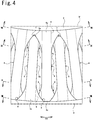
- is an enlarged view of region IV in
FIG. 1 ; - FIG. 5
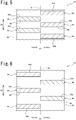
- is a drawing showing joints between connecting portions and the inner annular portion as these would exist if unwrapped so as to lie in a single plane at a non-pneumatic tire associated with a comparative example;
- FIG. 6
- is a drawing showing joints between connecting portions and the outer annular portion as these would exist if unwrapped so as to lie in a single plane at a non-pneumatic tire associated with same comparative example;
- FIG. 7
- is a view of a section taken along curve VII-VII in
FIG. 4 showing joints between connecting portions and the inner annular portion as these would exist if unwrapped so as to lie in a single plane; - FIG. 8
- is a view of a section taken along curve VIII-VIII in
FIG. 4 showing joints between connecting portions and the outer annular portion as these would exist if unwrapped so as to lie in a single plane; - FIG. 9
- is a view of a section taken along curve IX-IX in
FIG. 4 showing this as it would exist if unwrapped so as to lie in a single plane; - FIG. 10
- is a view of a section taken along curve X-X in
FIG. 4 showing this as it would exist if unwrapped so as to lie in a single plane; - FIG. 11
- is a side view of the principal components of a non-pneumatic tire associated with another embodiment in which only one connecting portion is shown;
- FIG. 12
- is a side view of the principal components of a non-pneumatic tire associated with yet another embodiment in which only one connecting portion is shown;
- FIG. 13
- is a view of a section taken along the tire circumferential direction at a non-pneumatic tire associated with yet another embodiment showing the situation as it would exist if unwrapped so as to lie in a single plane as viewed from a location toward the interior therefrom in the tire radial direction;
- FIG. 14
- is a view of a section taken along the tire circumferential direction at a non-pneumatic tire associated with the same embodiment showing the situation as it would exist if unwrapped so as to lie in a single plane as viewed from a location toward the exterior therefrom in the tire radial direction;
- FIG. 15
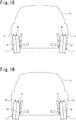
- is a drawing in which a non-pneumatic tire associated with the same embodiment is mounted on a vehicle;
- FIG. 16
- is a drawing in which a non-pneumatic tire associated with the same embodiment is mounted on a vehicle;
- FIG. 17
- is a side view of the principal components of a non-pneumatic tire
associated with yet another embodiment; and - FIG. 18
- is a perspective view of the principal components of a non-pneumatic tire associated with the same embodiment in which only two connecting portions are shown.
- Below, an embodiment of a non-pneumatic tire is described with reference to
FIG. 1 through FIG. 10 . At the respective drawings (and the same is true forFIG. 11 through FIG. 18 ), note that dimensional ratios at the drawings and actual dimensional ratios are not necessarily consistent, and note further that dimensional ratios are not necessarily consistent from drawing to drawing. - As shown in
FIG. 1 , a non-pneumatic tire (hereinafter sometimes referred to as simply "tire") 1 associated with the present embodiment comprises asupport structure 1a which supports the load from a vehicle. Thesupport structure 1a comprises an innerannular portion 2 and an outerannular portion 3 which are arranged in concentric fashion, and a plurality of connectingportions annular portion 2 and the outerannular portion 3. Note that the outerannular portion 3 is arranged at a location toward the exterior from the innerannular portion 2 in such a fashion that the innerannular portion 2 is contained therewithin, the connectingportions annular portion 2 and the outerannular portion 3. - At the respective drawings, a first direction D1 is the tire width direction D1 which is parallel to an
axis 1b which is the axis of rotation of thetire 1, a second direction D2 is the tire radial direction D2 which is the direction of the diameter of thetire 1, and a third direction D3 is the tire circumferential direction D3 which is the direction that is circumferential about theaxis 1b. Furthermore, a tire equatorial plane S1 is a plane that is located centrally in the tire width direction D1 of thetire 1 and that is perpendicular to theaxis 1b, and tire meridional planes are planes that are perpendicular to tire equatorial plane S1 and that contain theaxis 1b. - In the tire width direction D1, note that the side toward the interior is the side which is nearer to the tire equatorial plane S1, and note that the side toward the exterior is the side which is farther from the tire equatorial plane S1. Furthermore, in the tire radial direction D2, the side toward the interior is the side which is nearer to the
axis 1b, and the side toward the exterior is the side which is farther from theaxis 1b. - Furthermore, to reinforce the
support structure 1a, thetire 1 comprises a reinforcinglayer 1c which is arranged at a location toward the exterior from thesupport structure 1a, and atread region 1d which comes in contact with the ground and which is arranged at a location toward the exterior from the reinforcinglayer 1c. Furthermore, while not shown in the drawings, thetire 1 may be such that member(s), e.g., for accommodation of wheel hub(s) and/or rim(s), are provided at location(s) toward the interior from thesupport structure 1a. For example, so as to allow it to be mounted on a wheel hub and/or rim, it is preferred that the inner circumferential surface of the innerannular portion 2 be provided with intercuspation or the like for maintenance of engagement characteristics. - While there is no particular limitation with respect to the material(s) employed at the
support structure 1a, thesupport structure 1a might, for example, be formed from elastic material(s). Furthermore, polyester elastomer(s) and/or other such thermoplastic elastomer(s), natural rubber(s) and/or other such crosslinked rubber(s), and/or other resin(s) (e.g., polyethylene resin(s) and/or other such thermoplastic resin(s), and/or polyurethane resin(s) and/or other such thermosetting resin(s)) might, for example, be employed as base material(s) at thesupport structure 1a. Furthermore, fiber(s) and/or metal cord(s) and/or other such reinforcing material(s) might, for example, be embedded at the interior of such base material(s). - The reinforcing
layer 1c might, for example, be constituted such that steel cord(s), or CFRP, GFRP, or other such fiber-reinforced plastic cord(s) are arrayed in more or less parallel fashion with respect to the tire width direction D1, or from cylindrical metal ring(s), high-modulus resin ring(s), or the like. Furthermore, thetread region 1d might, for example, be constituted from rubber, resin, or the like in similar fashion as a conventional pneumatic tire, and may be provided with patterning (grooves) at the outer circumferential surface thereof in similar fashion as a conventional pneumatic tire. - It is preferred from the standpoint of improving uniformity that the inner
annular portion 2 be, for example, cylindrical and of constant thickness (here understood to mean not only the situation in which this is the same but also situations in which this is approximately the same such as when there are manufacturing errors and/or other such errors). Moreover, while there is no particular limitation with respect thereto, the thickness (dimension in the tire radial direction D2) of the innerannular portion 2 might, for example, be chosen as appropriate from the standpoint of ensuring improvement in weight reduction and endurance while permitting adequate transmission of force to the connectingportions - While there is no particular limitation with respect thereto, the inside diameter of the inner
annular portion 2 might, for example, be chosen as appropriate to accommodate the dimensions and so forth of the rim and/or wheel hub on which thetire 1 is to be mounted. Furthermore, while there is no particular limitation with respect thereto, the width (dimension in the tire width direction D1) of the innerannular portion 2 might, for example, be chosen as appropriate in correspondence to the intended usage thereof, axle length, and so forth. - It is preferred from the standpoint of improving uniformity that the outer
annular portion 3 be, for example, cylindrical and of constant thickness (here understood to mean not only the situation in which this is the same but also situations in which this is approximately the same). Moreover, while there is no particular limitation with respect thereto, the thickness (dimension in the tire radial direction D2) of the outerannular portion 3 might, for example, be chosen as appropriate from the standpoint of ensuring improvement in weight reduction and endurance while permitting adequate transmission of force from the connectingportions - While there is no particular limitation with respect thereto, the inside diameter of the outer
annular portion 3 might, for example, be chosen as appropriate in correspondence to the intended usage thereof and so forth. Furthermore, while there is no particular limitation with respect thereto, the width (dimension in the tire width direction D1) of the outerannular portion 3 might, for example, be chosen as appropriate in correspondence to the intended usage thereof and so forth. Moreover, it is preferred that the width of the outerannular portion 3 be the same as the width of the innerannular portion 2. - As shown in
FIG. 2 andFIG. 3 , the connectingportions portions portions portions 4 and a plurality of second connectingportions 5. - The first connecting
portions 4 extend in such fashion as to be directed from the first side (the right side inFIG. 2 andFIG. 3 ; hereinafter also referred to as the "first width direction side") D1a in the tire width direction D1 of the innerannular portion 2 toward the second side (the left side inFIG. 2 andFIG. 3 ; hereinafter also referred to as the "second width direction side") D1b in the tire width direction D1 of the outerannular portion 3. Furthermore, the second connectingportions 5 extend in such fashion as to be directed from the second width direction side D1b of the innerannular portion 2 toward the first width direction side D1a of the outerannular portion 3. - Thus, as viewed in the tire circumferential direction D3, the first connecting
portion 4 and the second connectingportion 5 extend so as to be inclined in mutually opposite directions. In addition, the first connectingportion 4 and the second connectingportion 5 appear to intersect as viewed in the tire circumferential direction D3. This causes formation between the first connectingportion 4 and the second connectingportion 5 of what appear to be closed space(s) 1e as viewed in the tire circumferential direction D3. As a result, because this makes it possible to increase elasticity, it is possible to improve performance with respect to ride comfort. - In addition, the first connecting
portions 4 and the second connectingportions 5 are arrayed in alternating fashion in the tire circumferential direction D3. This will make it possible to further reduce distribution of contact patch pressure during driving. Moreover, in accordance with the present embodiment, the first connectingportions 4 and the second connectingportions 5 are shaped so as to be symmetric with respect to the tire equatorial plane S1 as viewed in the tire circumferential direction D3. - Furthermore, widths (dimension in the tire width direction D1) of
inner end portions portions central portions portions outer end portions portions central portions portions portions central portions central portions end portions - While there is no particular limitation with respect thereto, the widths of the connecting
portions annular portion 2 and the outerannular portion 3. Furthermore, while there is no particular limitation with respect thereto, thicknesses (width dimension as viewed in the tire width direction D1) of the connectingportions annular portion 2 and the outerannular portion 3. - While there is no particular limitation with respect thereto, the relationship (relative magnitudes; ratios) between widths and thicknesses of the connecting
portions portions portions - A plurality of connecting
portions portions - As shown in
FIG. 3 andFIG. 4 , the connectingportions main body portions 6, the thicknesses of which are constant (here understood to mean not only the situation in which these are the same but also situations in which these are approximately the same), and reinforcingportions annular portion main body portions 6. The reinforcingportions portions 7 that cause the innerannular portion 2 to be coupled to tire circumferential direction D3 sides of themain body portions 6, and the outer reinforcingportions 8 that cause the outerannular portion 3 to be coupled to tire circumferential direction D3 sides of themain body portions 6. - At
FIGS. 3 and4 (and the same is true forFIGS. 7 and 8 , andFIGS. 11 and 12 , andFIGS. 17 and 18 ), note that boundaries between themain body portions 6 and the reinforcingportions main body portions 6 and the reinforcingportions - The
central portions portions main body portions 6;inner end portions portions main body portions 6 and the inner reinforcingportions 7; andouter end portions portions main body portions 6 and the outer reinforcingportions 8. This makes it possible to increase the rigidity of the connectingportions - Accordingly, because it will be possible, for example, to suppress occurrence of situations in which the connecting
portions annular portion 3. And because it will also be possible, for example, to reduce concentration of stress at theend portions portions - Moreover, thicknesses of the
inner end portions portions central portions portions outer end portions portions central portions portions portions central portions central portions end portions - As a result, thicknesses (dimension visible in the tire width direction D1) of the inner reinforcing
portions 7 increase as one proceeds toward the interior in the tire radial direction D2. Moreover, thicknesses (dimension visible in the tire width direction D1) of the outer reinforcingportions 8 increase as one proceeds toward the exterior in the tire radial direction D2. - It so happens that forces from the wheel hub might, for example, arrive at the inner
annular portion 2 by way of the rim or the like. In addition, forces from the wheel hub are transmitted in the following order: the innerannular portion 2, the connectingportions annular portion 3. Accordingly, for forces from the wheel hub to be effectively transmitted to thetread region 1d (seeFIG. 1 ), transmission of forces at upstream locations will be important. - For example, if forces are subject to large losses at upstream locations, i.e., if the connecting
portions tread region 1d to make contact with the ground in properly oriented fashion. As a result, the poor shape of the contact patch will cause decreased ability for forces from the wheel hub to be transmitted to the surface (tread surface) of the tread region Id. - At the respective connecting
portions portions 7 are greater than volumes of outer reinforcingportions 8. This makes it possible to increase rigidity at locations toward the interior in the tire radial direction D2 of the connectingportions annular portion 3. - Furthermore, the size of the gaps between the connecting
portions portions 7 is comparatively large, the pivot point (inflection point) during elastic deformation in the tire circumferential direction D3 of the connectingportions portions portions - Moreover, while the reinforcing
portions portions tire 1 to become too large this might, for example, cause increase in rolling resistance or the like. In this regard, because the volume of the outer reinforcingportions 8 is comparatively small, it is possible to suppress occurrence of situations in which the weight of thetire 1 might otherwise become too large. - At the
tire 1 associated with the present embodiment, as viewed in the tire width direction D1, the connectingportions portions portions 7 of the connectingportions inner end portions portions portions 8 of the connectingportions outer end portions portions - Even more specifically, the inner reinforcing
portions 7 of the connectingportions main body portions 6 of adjacent connectingportions portions 8 of the connectingportions main body portions 6 of adjacent connectingportions main body portions 6 of the connectingportions main body portions 6 of adjacent connectingportions - The inner reinforcing
portions 7 of the first connectingportions 4 are contiguous with the inner reinforcingportions 7 of the first connectingportions 4 that are adjacent with respect thereto in the tire circumferential direction D3. Although not shown inFIG. 4 , note that the inner reinforcingportions 7 of the second connectingportions 5 are also contiguous with the inner reinforcingportions 7 of the second connectingportions 5 that are adjacent with respect thereto in the tire circumferential direction D3. Thus, the inner reinforcingportions portions portions portions - Furthermore, the outer reinforcing
portions 8 of the second connectingportions 5 are separated from the outer reinforcingportions 8 of the second connectingportions 5 that are adjacent thereto in the tire circumferential direction D3. Although not shown inFIG. 4 , note that the outer reinforcingportions 8 of the first connectingportions 4 are also separated from the outer reinforcingportions 8 of the first connectingportions 4 that are adjacent thereto in the tire circumferential direction D3. Thus, the outer reinforcingportions portions portions portions -
Joints portions annular portions FIG. 5 through FIG. 10 . Below, thejoints portions annular portion 2 are referred to asinner joints joints portions annular portion 3 are referred to asouter joints - Tire X1 associated with a comparative example will first be described with reference to
FIG. 5 and FIG. 6 . As shown inFIG. 5 and FIG. 6 , unlike thetire 1 of the present embodiment, the tire X1 associated with the comparative example does not comprise reinforcingportions - As shown in
FIG. 5 , tire X1 associated with the comparative example is such that the inner joints X4d, X5d of adjacent connecting portions X4, X5 are separated from each other in the tire circumferential direction D3. Furthermore, as shown inFIG. 6 , the outer joints X4e, X5e of adjacent connecting portions X4, X5 are separated from each other in the tire circumferential direction D3. - As a result, regions in which joints X4d, X5d (X4e, X5e) are present, and regions in which joints X4d, X5d (X4e, X5e) are not present, are provided in alternating fashion in the tire circumferential direction D3. Accordingly, there will be occurrence of localized differences in rigidity in the tire circumferential direction D3.
- Furthermore, other joint(s) X4d, X4e, X5d, X5e are not present in region(s) at the tire width direction D1 side(s) of region(s) in which joint(s) X4d, X4e, X5d, X5e are present. Accordingly, there will also be occurrence of localized differences in rigidity in the tire width direction D1.
- The
inner joints tire 1 associated with the present embodiment will next be described with reference toFIG. 7 andFIG. 9 . - As shown in
FIG. 7 andFIG. 9 , at thetire 1 associated with the present embodiment, theinner joints portions inner joints portions - Furthermore, as viewed in the tire width direction D1, the
inner joints inner joints main body portions 6 are joined to the innerannular portion 2. As a result, theinner joints portions portions main body portions 6 are joined to the innerannular portion 2. Accordingly, this will make it possible to suppress occurrence of localized differences in rigidity in the tire width direction D1. - Moreover, whereas the portions of the
inner joints main body portions 6 are joined to the innerannular portion 2, the volumes ofinner portions 7a in the tire width direction D1 of the inner reinforcingportions 7 are greater than the volumes ofouter portions 7b in the tire width direction D1 of the inner reinforcingportions 7. - Moreover, the
inner portion 7a is that portion which is toward the interior in the tire width direction D1 when the inner reinforcingportion 7 is bisected in the tire width direction D1, and theouter portion 7b is that portion which is toward the exterior in the tire width direction D1 when the inner reinforcingportion 7 is bisected in the tire width direction D1. AtFIG. 9 , the boundary between theinner portion 7a and theouter portion 7b is shown in broken line. - As a result, the
main body portion 6 of the first connectingportion 4, theinner portion 7a of the inner reinforcingportion 7 of adjacent second connectingportion 5, andouter portion 7b of the inner reinforcingportion 7 of said second connectingportion 5 are arranged in this order from first width direction side D1a to second width direction side D1b. Furthermore,main body portion 6 of second connectingportion 5, theinner portion 7a of the inner reinforcingportion 7 of adjacent first connectingportion 4, andouter portion 7b of the inner reinforcingportion 7 of said first connectingportion 4 are arranged in this order from second width direction side D1b to first width direction side D1a. - That is, this makes it possible for
main body portion 6 of connectingportion inner portion 7a of the inner reinforcingportion 7 of adjacent connectingportion outer portion 7b of the inner reinforcingportion 7 of adjacent connectingportion - It will thus be possible to suppress occurrence of localized differences in rigidity in the tire width direction D1 and in the tire circumferential direction D3 at
inner end portions portions annular portion 2. Accordingly, because it will be possible to suppress occurrence of situations in there might otherwise be concentration of stress, this will make it possible, for example, to cause forces from the wheel hub to be uniformly transmitted to the outerannular portion 3 by way of the innerannular portion 2 and the connectingportions - The
outer joints tire 1 associated with the present embodiment will next be described with reference toFIG. 8 andFIG. 10 . - As shown in
FIG. 8 andFIG. 10 , at thetire 1 associated with the present embodiment, theouter joints portions outer joints portions - Furthermore, as viewed in the tire width direction D1, the
outer joints outer joints main body portions 6 are joined to the outerannular portion 3. As a result, theouter joints portions portions main body portions 6 are joined to the outerannular portion 3. Accordingly, this will make it possible to suppress occurrence of localized differences in rigidity in the tire width direction D1. - Moreover, whereas the portions of the
outer joints main body portions 6 are joined to the outerannular portion 3, volumes of theinner portions 8a in the tire width direction D1 of the outer reinforcingportions 8 are greater than volumes ofouter portions 8b in the tire width direction D1 of outer reinforcingportions 8. - Moreover, the
inner portion 8a is that portion which is toward the interior in the tire width direction D1 when the outer reinforcingportions 8 are bisected in the tire width direction D1, andouter portion 8b is that portion which is toward the exterior in the tire width direction D1 when the outer reinforcingportions 8 are bisected in the tire width direction D1. AtFIG. 10 , the boundary between theinner portion 8a and theouter portion 8b is shown in broken line. - As a result, the
main body portion 6 of second connectingportion 5, theinner portion 8a of the outer reinforcingportions 8 of adjacent first connectingportion 4, and theouter portion 8b of the outer reinforcingportion 8 of said first connectingportion 4 are arranged in this order from the first width direction side D1a to the second width direction side D1b. Furthermore, themain body portion 6 of first connectingportion 4, theinner portion 8a of the outer reinforcingportion 8 of the adjacent second connectingportion 5, and theouter portion 8b of the outer reinforcingportion 8 of said second connectingportion 5 are arranged in this order from the second width direction side D1b to the first width direction side D1a. - That is, this makes it possible for the
main body portion 6 of the connectingportion inner portion 8a of the outer reinforcingportion 8 of the adjacent connectingportion outer portion 8b of the outer reinforcingportion 8 of the adjacent connectingportion - It will thus be possible to suppress occurrence of localized differences in rigidity in the tire width direction D1 and in the tire circumferential direction D3 at the
outer end portions portions annular portion 3. Accordingly, because it will be possible to suppress occurrence of situations in there might otherwise be concentration of stress, this will make it possible, for example, to cause contact patch pressure of thetire 1 with respect to the road surface to be made uniform. - As described above, the
non-pneumatic tire 1 of the embodiment includes: - an inner
annular portion 2 and an outerannular portion 3 that are arranged in concentric fashion; and - a plurality of connecting
portions annular portion 2 and the outerannular portion 3; - wherein the plurality of connecting
portions portions 4 extending in such fashion as to be directed from a first side D1a in a tire width direction D1 of the innerannular portion 2 toward a second side D1b in the tire width direction D1 of the outerannular portion 3, and the second connectingportions 5 extending in such a fashion as to be directed from the second side D1b in the tire width direction D1 of the innerannular portion 2 toward the first side D1a in the tire width direction D1 of the outerannular portion 3; and - wherein at least one of the plurality of the connecting
portions main body portion 6 having a width that is constant or that increases in tapered fashion by a constant ratio ("that is constant" in this embodiment) as viewed in the tire width direction D1, and an reinforcing portion 7(8) that connects an end in a tire circumferential direction D3 of themain body portion 6 and the annular portion 2(3). - In accordance with such a constitution, because reinforcing portion(s) 7, 8 connect at least one of either the inner
annular portion 2 or the outerannular portion 3 with tire circumferential direction D3 side(s) of main body portion(s) 6, the connectingportions portions - Further, in the
non-pneumatic tire 1 of the embodiment,
wherein the reinforcingportions portion 7 connects an end in a tire circumferential direction D3 of themain body portion 6 and the innerannular portion 2, the outer reinforcingportion 8 connects an end in a tire circumferential direction D3 of themain body portion 6 and the outerannular portion 3; and
volume of the inner reinforcingportion 7 is greater than volume of the outer reinforcingportion 8. - In accordance with such a constitution, whereas forces from the wheel hub are transmitted in order from the inner
annular portion 2 to the connectingportions annular portion 3, volumes of the inner reinforcingportions 7 are comparatively large. This makes it possible to increase the rigidity of the wheel hub side of the connectingportions - Further, in the
non-pneumatic tire 1 of the embodiment,
wherein the first connectingportions 4 and the second connectingportions 5 are arrayed in alternating fashion in the tire circumferential direction D3;
as viewed in the tire width direction D1, themain body portion 6 of at least one of the first connectingportions 4 appears to be separated in the tire circumferential direction D3 from themain body portion 6 of an adjacent one of the second connectingportions 5 which is adjacent to the at least one first connectingportion 4 in the tire circumferential direction D3;
the at least one first connectingportion 4 comprises a first joint 4d(4e) by which the at least one first connectingportion 4 is joined to the annular portion 2(3);
the adjacent second connectingportion 5 comprises a second joint 5d(5e) by which the adjacent second connectingportion 5 is joined to the annular portion 2(3); and
the first joint 4d(4e) appears to overlap the second joint 5d(5e) as viewed in the tire width direction D1. - In accordance with such a constitution, the
joints portions - Further, in the
non-pneumatic tire 1 of the embodiment,
wherein the adjacent second connectingportion 5 comprises a main body joint by which themain body portion 6 of the adjacent second connectingportion 5 is joined to the annular portion 2(3); and
the first joint 4d(4e) appears to overlap the main body joint of the adj acent second connectingportion 5 as viewed in the tire width direction D1. - In accordance with such a constitution, the
joints 4d (4e) of adjacent first connectingportions 4 are present in regions at tire width direction D1 sides of regions at locations on the second connectingportions 5 at which themain body portions 6 are joined to annular portion 2 (3). This makes it possible to suppress occurrence of localized differences in rigidity in the tire width direction D1. - Further, in the
non-pneumatic tire 1 of the embodiment,
wherein the reinforcingportion portion 4 comprises aninner portion outer portion
division into theinner portion outer portion portion
volume of theinner portion outer portion - In accordance with such a constitution, because the volume of the
inner portion main body portion 6 of adjacent connectingportion annular portion inner portion portion portion outer portion portion portion - The
non-pneumatic tire 1 is not limited to the configuration of the embodiment described above, and the effects are not limited to those described above. It goes without saying that thenon-pneumatic tire 1 can be variously modified without departing from the scope of the subject matter of the present invention. For example, the constituents, methods, and the like of various modified examples described below may be arbitrarily selected and employed as the constituents, methods, and the like of the embodiments described above, as a matter of course. - (1) The constitution of the
non-pneumatic tire 1 associated with the foregoing embodiment is such that widths of themain body portions 6 appear to be constant as viewed in the tire width direction D1. However, thenon-pneumatic tire 1 is not limited to such constitution. For example, as shown inFIG. 11 , it is also possible to adopt a constitution in which the width as viewed in the tire width direction D1 ofmain body portion 6 increases in tapered fashion by a constant (here understood to mean not only the situation in which this is the same but also situations in which this is approximately the same) ratio.
Thus, as viewed in the tire width direction D1, the boundary of main body portion 6 (more specifically, the boundary betweenmain body portion 6 and reinforcingportion main body portion 6 associated withFIG. 11 increases as one proceeds toward the exterior in the tire radial direction D2, there is no limitation with respect to such constitution. For example, it is also possible to adopt a constitution in which the width as viewed in the tire width direction D1 of themain body portion 6 increases as one proceeds toward the interior in the tire radial direction D2. - (2) Furthermore, the constitution of the
non-pneumatic tire 1 associated with the foregoing embodiment is such that the connectingportions portions 7 and the outer reinforcingportions 8. However, thenon-pneumatic tire 1 is not limited to such constitution. For example, it is also possible to adopt a constitution in which the connectingportions portions 8 and are not provided with the inner reinforcingportions 7. - (2-1) Furthermore, for example as shown in
FIG. 12 , it is also possible to adopt a constitution in which the connectingportions portions 7 and are not provided with outer reinforcingportions 8. In accordance with such constitution, whereas the size of gaps between adjacent connectingportions portions portions portions - (3) Furthermore, the constitution of the
non-pneumatic tire 1 associated with the foregoing embodiment is such that all of the connectingportions portions non-pneumatic tire 1 is not limited to such constitution. For example, it is also possible to adopt a constitution in which there is one connectingportion portions portions - (4) Furthermore, the constitution of the
non-pneumatic tire 1 associated with the foregoing embodiment is such that the first connectingportions 4 and the second connectingportions 5 are shaped so as to be symmetric with respect to the tire equatorial plane S1 as viewed in the tire circumferential direction D3. However, thenon-pneumatic tire 1 is not limited to such constitution. For example, as shown inFIG. 13 and FIG. 14 , it is also possible to adopt a constitution in which the first connectingportions 4 and the second connectingportions 5 are shaped so as to be asymmetric with respect to the tire equatorial plane S1 as viewed in the tire circumferential direction D3. - (4-1) The
non-pneumatic tire 1 associated withFIG. 13 and FIG. 14 is provided with a first width portion If which is the portion on the first width direction side D1a of the tire equatorial plane S1, and asecond width portion 1g which is the portion on the second width direction side D1b of the tire equatorial plane S1. Furthermore, thetire 1 may be mounted on a vehicle in such fashion that the first width portion If is on the outboard side thereof, or it may be mounted on a vehicle in such a fashion that thesecond width portion 1g is on the outboard side thereof.
The volume of the inner reinforcingportions 7 at the first width portion If is greater than the volume of the inner reinforcingportions 7 at thesecond width portion 1g. That is, the volume of the inner reinforcingportions 7 of the first connectingportions 4 is greater than the volume of the inner reinforcingportions 7 of the second connectingportions 5. Furthermore, the volume of the outer reinforcingportions 8 at the first width portion If is greater than the volume of the outer reinforcingportions 8 at thesecond width portion 1g. That is, the volume of the outer reinforcingportions 8 of the second connectingportions 5 is greater than the volume of the outer reinforcingportions 8 of the first connectingportions 4.
Accordingly, the total volume of the reinforcingportions portions second width portion 1g. In the context of a constitution in which the total volume of the reinforcingportions portions second width portion 1g, there is no particular limitation with respect to the relative magnitudes of the total volume of the inner reinforcingportions 7 at the first width portion If and the total volume of the inner reinforcingportions 7 at thesecond width portion 1g, or with respect to the relative magnitudes of the total volume of the outer reinforcingportions 8 at the first width portion If and the total volume of the outer reinforcingportions 8 atsecond width portion 1g.
In addition, for example as shown inFIG. 15 , in a situation in which thetire 1 is mounted on vehicle Y1 in such a fashion as to have positive camber, thetire 1 may be mounted on vehicle Y1 in such a fashion that the first width portion If is on the outboard side thereof. This makes it possible to increase rigidity at outboard locations when thetire 1 is mounted on a vehicle.
Accordingly, because this will make it possible to suppress occurrence of strain at outboard locations where load is comparatively large, this will make it possible to reduce rolling resistance of thetire 1, as a result of which it will be possible to improve the fuel consumption efficiency of the vehicle. And because it will also be possible, for example, even where the slip angle of thetire 1 is large, to cause production of large cornering forces, this will also make it possible to improve performance with respect to stability in handling during turns.
Furthermore, for example as shown inFIG. 16 , in a situation in which thetire 1 is mounted on a vehicle Y1 in such fashion as to have negative camber, thetire 1 may be mounted on the vehicle Y1 in such a fashion that the first width portion If is on the inboard side thereof. This makes it possible to increase rigidity at inboard locations when thetire 1 is mounted on a vehicle. Accordingly, because this will make it possible to suppress occurrence of strain at inboard locations where load is comparatively large, this will make it possible to reduce rolling resistance of thetire 1, as a result of which it will be possible to improve the fuel consumption efficiency of the vehicle.
Thus, the constitution of thenon-pneumatic tire 1 associated withFIG. 13 and FIG. 14 is such that that portion of the total volume of all of the inner reinforcingportions 7 and all of the outer reinforcingportions 8 which are disposed on the first side D1a in the tire width direction D1 of a tire equatorial plane S1 is greater than that portion of the total volume of all of the inner reinforcingportions 7 and all of the outer reinforcingportions 8 which are disposed on the second side D1b in the tire width direction D1 of the tire equatorial plane S1.
In accordance with such a constitution, because the total volume of the plurality of the reinforcingportions - (5) Furthermore, the constitution of the
non-pneumatic tire 1 associated with the foregoing embodiment is such that this is atire 1 for which a vehicle mounting orientation is not indicated. However, thenon-pneumatic tire 1 is not limited to such a constitution. For example, it is also possible to adopt a constitution in which thenon-pneumatic tire 1 is atire 1 for which a vehicle mounting direction is indicated. Note that in accordance with such a constitution thetire 1 may comprise, e.g., at a side face portion of thesupport structure 1a, an indicator region that indicates an orientation in which the tire is to be mounted on the vehicle.- (5-1) For example, when the
tire 1 is mounted on a vehicle, large forces act at inboard locations of thetire 1 during braking. For this reason, the constitution may be such that the total volume of the reinforcingportions portions - (5-2) Furthermore, for example, when the
tire 1 is mounted on a vehicle, large forces act at outboard locations of thetire 1 when thetire 1 is an outside wheel during a turn. For this reason, the constitution may be such that the total volume of the reinforcingportions portions - (5-3) Furthermore, for example, when the
tire 1 is mounted on a vehicle, whereas large forces act at inboard locations of thetire 1 during braking, for forces from the wheel hub to be effectively transmitted to thetread region 1d at such a time, transmission of forces at locations toward the interior in the tire radial direction D2 will be important. On the other hand, for example, when thetire 1 is mounted on a vehicle, whereas large forces act at outboard locations of thetire 1 when thetire 1 is an outside wheel during a turn, larger forces will act at locations toward the exterior in the tire radial direction D2 as a result of contact with the road surface at such time.
For this reason, the constitution may be such that the total volume of the inner reinforcingportions 7 at locations which will be to the inboard side of the tire equatorial plane S1 when mounted on a vehicle is greater than the total volume of the inner reinforcingportions 7 at locations which will be to the outboard side of the tire equatorial plane S1 when mounted on a vehicle, and such that total volume of the outer reinforcingportions 8 at locations which will be to the outboard side of the tire equatorial plane S1 when mounted on a vehicle is greater than the total volume of the outer reinforcingportions 8 at locations which will be to the inboard side of the tire equatorial plane S1 when mounted on a vehicle. Such a constitution will make it possible to improve braking performance and performance during turns.
- (5-1) For example, when the
- (6) Furthermore, the constitution of the
non-pneumatic tire 1 associated with the foregoing embodiment is such that the volume of the inner reinforcingportions 7 is greater than the volume of the outer reinforcingportions 8. However, while such a constitution is preferred, thenon-pneumatic tire 1 is not limited to such constitution. For example, it is also possible to adopt a constitution in which the volume of the inner reinforcingportions 7 is not greater than the volume of the outer reinforcingportions 8. - (7) Furthermore, the constitution of the
non-pneumatic tire 1 associated with the foregoing embodiment is such that the first connectingportions 4 and the second connectingportions 5 are arrayed in alternating fashion in the tire circumferential direction D3. However, while such a constitution is preferred, thenon-pneumatic tire 1 is not limited to such constitution. It is also possible to adopt a constitution in which, for example, a portion of the first connectingportions portions - (8) Furthermore, the constitution of the
non-pneumatic tire 1 associated with the foregoing embodiment is such that themain body portions 6 of the connectingportions main body portions 6 of adjacent connectingportions non-pneumatic tire 1 is not limited to such a constitution. For example, it is also possible to adopt a constitution in which themain body portions 6 of the connectingportions main body portions 6 of adjacent connectingportions - (9) Furthermore, the constitution of the
non-pneumatic tire 1 associated with the foregoing embodiment is such that theinner joints portions inner joints portions non-pneumatic tire 1 is not limited to such constitution. For example, it is also possible to adopt a constitution in which theinner joints portions inner joints portions - (10) Furthermore, the constitution of the
non-pneumatic tire 1 associated with the foregoing embodiment is such that theouter joints portions outer joints portions non-pneumatic tire 1 is not limited to such constitution. For example, it is also possible to adopt a constitution in which theouter joints portions outer joints portions - (11) Furthermore, the constitution of the
non-pneumatic tire 1 associated with the foregoing embodiment is such that theinner joints portions main body portions 6 of adjacent connectingportions annular portion 2 as viewed in the tire width direction D1. However, while such a constitution is preferred, thenon-pneumatic tire 1 is not limited to such a constitution. For example, it is also possible to adopt a constitution in which theinner joints portions main body portions 6 of adjacent connectingportions annular portion 2 as viewed in the tire width direction D1. - (12) Furthermore, the constitution of the
non-pneumatic tire 1 associated with the foregoing embodiment is such that theouter joints portions main body portions 6 of adjacent connectingportions annular portion 3 as viewed in the tire width direction D1. However, while such a constitution is preferred, thenon-pneumatic tire 1 is not limited to such a constitution. For example, it is also possible to adopt a constitution in which theouter joints portions main body portions 6 of adjacent connectingportions annular portion 3 as viewed in the tire width direction D1. - (13) Furthermore, the constitution of the
non-pneumatic tire 1 associated with the foregoing embodiment is such that the volumes of theinner portions portions outer portions portions non-pneumatic tire 1 is not limited to such a constitution. For example, it is also possible to adopt a constitution in which the volume of theinner portion 7a of the inner reinforcingportion 7 is not greater than the volume of theouter portion 7b of the inner reinforcingportion 7. Furthermore, for example, it is also possible to adopt a constitution in which the volume of theinner portion 8a of the outer reinforcingportion 8 is not greater than the volume ofouter portion 8b of the outer reinforcingportion 8. - (14) Furthermore, the constitution of the
non-pneumatic tire 1 associated with the foregoing embodiment is such that the inner reinforcingportions portions portions portions non-pneumatic tire 1 is not limited to such a constitution. For example, it is also possible to adopt a constitution in which the inner reinforcingportions portions portions portions - (15) Furthermore, the constitution of the
non-pneumatic tire 1 associated with the foregoing embodiment is such that the outer reinforcingportions portions portions portions non-pneumatic tire 1 is not limited to such a constitution. For example, it is also possible to adopt a constitution in which the outer reinforcingportions portions portions portions - (16) Furthermore, the constitution of the
non-pneumatic tire 1 associated with the foregoing embodiment is such that thicknesses (dimension visible in the tire width direction D1) of the inner reinforcingportions 7 increase as one proceeds toward the interior in the tire radial direction D2, and thicknesses (dimension visible in the tire width direction D1) of the outer reinforcingportions 8 increase as one proceeds toward the exterior in the tire radial direction D2. However, thenon-pneumatic tire 1 is not limited to such constitution. - For example, as shown in
FIG. 17 and FIG. 18 , it is also possible to adopt a constitution in which the thickness of the inner reinforcingportion 7 is constant (here understood to mean not only the situation in which this is the same but also situations in which this is approximately the same) everywhere therealong in the tire radial direction D2. Furthermore, as shown inFIG. 17 and FIG. 18 , it is also possible to adopt a constitution in which the thickness of the outer reinforcingportion 8 is constant (here understood to mean not only the situation in which this is the same but also situations in which this is approximately the same) everywhere therealong in the tire radial direction D2. - At the
non-pneumatic tire 1 associated withFIG. 17 and FIG. 18 , the inner reinforcingportions 7 extend in the tire circumferential direction D3 in such a fashion as to cause mutual coupling of adjacent first connectingportions 4, 4 (and mutual coupling of the second connectingportions 5, 5). Furthermore, the outer reinforcingportions 8 extend in the tire circumferential direction D3 in such fashion as to cause mutual coupling of adjacent first connectingportions 4, 4 (and mutual coupling of the second connectingportions 5, 5). -
- 1
- non-pneumatic tire
- 1a
- support structure
- 1b
- axis
- 1c
- reinforcing layer
- 1d
- tread region
- 1e
- closed space
- 1f
- first width portion
- 1g
- second width portion
- 2
- inner annular portion
- 3
- outer annular portion
- 4
- first connecting portion
- 4a
- inner end portion
- 4b
- central portion
- 4c
- outer end portion
- 4d
- inner joint
- 4e
- outer joint
- 5
- second connecting portion
- 5a
- inner end portion
- 5b
- central portion
- 5c
- outer end portion
- 5d
- inner joint
- 5e
- outer joint
- 6
- main body portion
- 7
- inner reinforcing portion
- 7a
- inner portion
- 7b
- outer portion
- 8
- outer reinforcing portion
- 8a
- inner portion
- 8b
- outer portion
- D1
- tire width direction
- D1a
- first width direction side
- D1b
- second width direction side
- D2
- tire radial direction
- D3
- tire circumferential direction
- S1
- tire equatorial plane
- Y1
- vehicle
Claims (13)
- A non-pneumatic tire (1) comprising:- an inner annular portion (2) and an outer annular portion (3) that are arranged in concentric fashion; and- a plurality of connecting portions (4, 5) that connect the inner annular portion (2) and the outer annular portion (3);- wherein the plurality of connecting portions (4, 5) comprises first connecting portions (4) extending in such a fashion as to be directed from a first side (D1a) in a tire width direction (D1) of the inner annular portion (2) toward a second side (D1b) in the tire width direction (D1) of the outer annular portion (3), and second connecting portions (5) extending in such a fashion as to be directed from the second side (D1b) in the tire width direction (D1) of the inner annular portion (2) toward the first side (D1a) in the tire width direction (D1) of the outer annular portion (3); and
wherein at least one of the plurality of connecting portions (4, 5) comprises a main body portion (6) having a width that is constant or that increases in tapered fashion by a constant ratio as viewed in the tire width direction (D1), and an inner reinforcing portion (7) that connects an end in a tire circumferential direction (D3) of the main body portion (6) and the inner annular portion (2). - A non-pneumatic tire (1) comprising:- an inner annular portion (2) and an outer annular portion (3) that are arranged in concentric fashion; and- a plurality of connecting portions (4, 5) that connect the inner annular portion (2) and the outer annular portion (3);
wherein the plurality of connecting portions (4, 5) comprises first connecting portions (4) extending in such a fashion as to be directed from a first side (D1a) in a tire width direction (D1) of the inner annular portion (2) toward a second side (D1b) in the tire width direction (D1) of the outer annular portion (3), and second connecting portions (5) extending in such a fashion as to be directed from the second side (D1b) in the tire width direction (D1) of the inner annular portion (2) toward the first side (D1a) in the tire width direction (D1) of the outer annular portion (3); and
wherein at least one of the plurality of connecting portions (4, 5) comprises a main body portion (6) having a width that is constant or that increases in tapered fashion by a constant ratio as viewed in the tire width direction (D1), and an outer reinforcing portion (8) that connects an end in a tire circumferential direction (D3) of the main body portion (6) and the outer annular portion (3). - The non-pneumatic tire (1) according to claim 1,
wherein the at least one of the plurality of connecting portions (4, 5) further comprises an outer reinforcing portion (8) that connects the end in the tire circumferential direction (D3) of the main body portion (6) and the outer annular portion (3). - The non-pneumatic tire (1) according to claim 3,
wherein the volume of the inner reinforcing portion (7) is greater than the volume of the outer reinforcing portion (8). - The non-pneumatic tire (1) according to claims 1, 3 or 4,- wherein the first connecting portions (4) and the second connecting portions (5) are arrayed in alternating fashion in the tire circumferential direction (D3);- as viewed in the tire width direction (D1), the main body portion (6) of at least one of the first connecting portions (4) appears to be separated in the tire circumferential direction from the main body portion (6) of an adjacent one of the second connecting portions (5) which is adjacent to the at least one first connecting portion (4) in the tire circumferential direction (D3);- the at least one first connecting portion (4) comprises a first inner joint (4d) by which the at least one first connecting portion (4) is joined to the inner annular portion (2);- the adjacent second connecting portion (5) comprises a second inner joint (5d) by which the adjacent second connecting portion (5) is joined to the inner annular portion (2); and- the first inner joint (4d) appears to overlap the second inner joint (5d) as viewed in the tire width direction (D1).
- The non-pneumatic tire (1) according to claim 5,
wherein the adjacent second connecting portion (5) comprises a main body joint by which the main body portion (6) of the adjacent second connecting portion (5) is joined to the inner annular portion (2); and
wherein the first inner joint (4d) appears to overlap the main body joint of the adjacent second connecting portion (5) as viewed in the tire width direction (D1). - The non-pneumatic tire (1) according to claim 6,
wherein the inner reinforcing portion (7) of the at least one first connecting portion (4) comprises an inner portion (7a) and an outer portion (7b) in the tire width direction (D1);
wherein division into the inner portion (7a) and the outer portion (7b) is based on bisection of the inner reinforcing portion (7) in the tire width direction (D1); and wherein the volume of the inner portion (7a) is greater than the volume of the outer portion (7b). - The non-pneumatic tire (1) according to any one of claims 2 to 4,- wherein the first connecting portions (4) and the second connecting portions (5) are arrayed in alternating fashion in the tire circumferential direction (D3);- as viewed in the tire width direction (D1), the main body portion (6) of at least one of the first connecting portions (4) appears to be separated in the tire circumferential direction (D3) from the main body portion (6) of an adjacent one of the second connecting portions (5) which is adjacent to the at least one first connecting portion (4) in the tire circumferential direction (D3);- the at least one first connecting portion (4) comprises a first outer joint (4e) by which the at least one first connecting portion (4) is joined to the outer annular portion (3);- the adjacent second connecting portion (5) comprises a second outer joint (5e) by which the adjacent second connecting portion (5) is joined to the outer annular portion (3); and- the first outer joint (4e) appears to overlap the second outer joint (5e) as viewed in the tire width direction (D1).
- The non-pneumatic tire (1) according to claim 8,
wherein the adjacent second connecting portion (5) comprises a main body joint by which the main body portion (6) of the adjacent second connecting portion (5) is joined to the outer annular portion (3); and
wherein the first outer joint (4e) appears to overlap the main body joint of the adjacent second connecting portion (5) as viewed in the tire width direction (D1). - The non-pneumatic tire (1) according to claim 9,
wherein the outer reinforcing portion (8) of the at least one first connecting portion (4) comprises an inner portion (8a) and an outer portion (8b) in the tire width direction (D1);
wherein division into the inner portion (8a) and the outer portion (8b) is based on bisection of the outer reinforcing portion (8) in the tire width direction (D1); and wherein the volume of the inner portion (8a) is greater than the volume of the outer portion (8b). - The non-pneumatic tire (1) according to any one of claims 3 to 7
wherein the first connecting portions (4) and the second connecting portions (5) are arrayed in alternating fashion in the tire circumferential direction (D3); and wherein the inner reinforcing portion (7) of at least one of the first connecting portions (4) is contiguous with the inner reinforcing portion (7) of an adjacent one of the first connecting portions (4) which is adjacent to the at least one first connecting portion (4) in the tire circumferential direction (D3). - The non-pneumatic tire (1) according to any one of claims 2 to 4 and 8 to 11, wherein the first connecting portions (4) and the second connecting portions (5) are arrayed in alternating fashion in the tire circumferential direction (D3); and wherein the outer reinforcing portion (8) of at least one of the first connecting portions (4) is separated in the tire circumferential direction (D3) from the outer reinforcing portion (8) of an adjacent one of the first connecting portions (4) which is adjacent to the at least one first connecting portion (4) in the tire circumferential direction (D3).
- The non-pneumatic tire (1) according to any one of claims 1 to 12
wherein that portion of the total volume of all of the reinforcing portions (7, 8) which is disposed on the first side (D1a) in the tire width direction (D1) of a tire equatorial plane (S1) is greater than that portion of the total volume of all of the reinforcing portions (7, 8) which is disposed on the second side (D1b) in the tire width direction (D1) of the tire equatorial plane (S1).
Applications Claiming Priority (1)
| Application Number | Priority Date | Filing Date | Title |
|---|---|---|---|
| JP2019190513A JP7321053B2 (en) | 2019-10-17 | 2019-10-17 | non-pneumatic tires |
Publications (2)
| Publication Number | Publication Date |
|---|---|
| EP3808572A1 true EP3808572A1 (en) | 2021-04-21 |
| EP3808572B1 EP3808572B1 (en) | 2023-04-05 |
Family
ID=72717711
Family Applications (1)
| Application Number | Title | Priority Date | Filing Date |
|---|---|---|---|
| EP20199528.9A Active EP3808572B1 (en) | 2019-10-17 | 2020-10-01 | Non-pneumatic tire |
Country Status (4)
| Country | Link |
|---|---|
| US (1) | US11731459B2 (en) |
| EP (1) | EP3808572B1 (en) |
| JP (1) | JP7321053B2 (en) |
| CN (1) | CN112677708B (en) |
Citations (5)
| Publication number | Priority date | Publication date | Assignee | Title |
|---|---|---|---|---|
| FR1071651A (en) * | 1952-03-06 | 1954-09-03 | Soft rim coating | |
| JP2015039986A (en) | 2013-08-22 | 2015-03-02 | 東洋ゴム工業株式会社 | Non-pneumatic tire |
| EP3446887A1 (en) * | 2017-08-24 | 2019-02-27 | Sumitomo Rubber Industries, Ltd. | Airless tire |
| US20190070903A1 (en) * | 2017-09-07 | 2019-03-07 | Toyo Tire & Rubber Co., Ltd. | Non-pneumatic tire |
| US20190070905A1 (en) * | 2017-09-07 | 2019-03-07 | Toyo Tire & Rubber Co., Ltd. | Non-pneumatic tire |
Family Cites Families (19)
| Publication number | Priority date | Publication date | Assignee | Title |
|---|---|---|---|---|
| US3018809A (en) * | 1959-11-10 | 1962-01-30 | Jules E Briche | Flexible non-pneumatic tire |
| US8631844B2 (en) * | 2005-06-13 | 2014-01-21 | Millenworks | Variable compliance wheel |
| US20090173421A1 (en) * | 2008-01-08 | 2009-07-09 | Freudenberg-Nok General Partnership | Flatless Hybrid Isolated Tire |
| JP5461303B2 (en) * | 2010-05-28 | 2014-04-02 | 東洋ゴム工業株式会社 | Non-pneumatic tire |
| WO2013152067A1 (en) * | 2012-04-05 | 2013-10-10 | Compagnie Generale Des Establissements Michelin | Spoke for a tire with optimized thickness for improved durability |
| JP5972149B2 (en) * | 2012-11-16 | 2016-08-17 | 東洋ゴム工業株式会社 | Non-pneumatic tire |
| JP6013899B2 (en) * | 2012-12-19 | 2016-10-25 | 東洋ゴム工業株式会社 | Non-pneumatic tire |
| JP6159138B2 (en) * | 2013-05-07 | 2017-07-05 | 住友ゴム工業株式会社 | Airless tire |
| EP3007909A4 (en) * | 2013-06-15 | 2017-03-01 | Ronald Thompson | Annular ring and non-pneumatic tire |
| JP6152036B2 (en) * | 2013-10-21 | 2017-06-21 | 株式会社ブリヂストン | Non pneumatic tire |
| JP6173903B2 (en) * | 2013-12-13 | 2017-08-02 | 東洋ゴム工業株式会社 | Non pneumatic tire |
| JP6619552B2 (en) * | 2014-11-07 | 2019-12-11 | 株式会社ブリヂストン | Non pneumatic tire |
| JP6383294B2 (en) * | 2015-01-13 | 2018-08-29 | 住友ゴム工業株式会社 | Airless tire |
| JP6397363B2 (en) * | 2015-04-03 | 2018-09-26 | 住友ゴム工業株式会社 | tire |
| JP2019043503A (en) * | 2017-09-07 | 2019-03-22 | Toyo Tire株式会社 | Non pneumatic tire |
| JP6964470B2 (en) * | 2017-09-07 | 2021-11-10 | Toyo Tire株式会社 | Non-pneumatic tire |
| JP6929764B2 (en) * | 2017-12-01 | 2021-09-01 | Toyo Tire株式会社 | Non-pneumatic tire |
| CN108032683A (en) * | 2017-12-05 | 2018-05-15 | 燕山大学 | A kind of non-inflatable tyre |
| JP7004562B2 (en) * | 2017-12-14 | 2022-02-10 | Toyo Tire株式会社 | Non-pneumatic tires |
-
2019
- 2019-10-17 JP JP2019190513A patent/JP7321053B2/en active Active
-
2020
- 2020-09-21 CN CN202010992509.4A patent/CN112677708B/en active Active
- 2020-09-24 US US17/030,811 patent/US11731459B2/en active Active
- 2020-10-01 EP EP20199528.9A patent/EP3808572B1/en active Active
Patent Citations (5)
| Publication number | Priority date | Publication date | Assignee | Title |
|---|---|---|---|---|
| FR1071651A (en) * | 1952-03-06 | 1954-09-03 | Soft rim coating | |
| JP2015039986A (en) | 2013-08-22 | 2015-03-02 | 東洋ゴム工業株式会社 | Non-pneumatic tire |
| EP3446887A1 (en) * | 2017-08-24 | 2019-02-27 | Sumitomo Rubber Industries, Ltd. | Airless tire |
| US20190070903A1 (en) * | 2017-09-07 | 2019-03-07 | Toyo Tire & Rubber Co., Ltd. | Non-pneumatic tire |
| US20190070905A1 (en) * | 2017-09-07 | 2019-03-07 | Toyo Tire & Rubber Co., Ltd. | Non-pneumatic tire |
Also Published As
| Publication number | Publication date |
|---|---|
| JP2021066215A (en) | 2021-04-30 |
| US20210114413A1 (en) | 2021-04-22 |
| US11731459B2 (en) | 2023-08-22 |
| EP3808572B1 (en) | 2023-04-05 |
| CN112677708B (en) | 2022-12-02 |
| JP7321053B2 (en) | 2023-08-04 |
| CN112677708A (en) | 2021-04-20 |
Similar Documents
| Publication | Publication Date | Title |
|---|---|---|
| EP3519204B1 (en) | Reinforced rubber spoke for a tire | |
| JP7414825B2 (en) | Tires for vehicles including stiffening structures | |
| US8851131B2 (en) | Skew symmetric non-pneumatic tire | |
| EP2505386B1 (en) | Pneumatic tire | |
| JP7032544B2 (en) | Non-pneumatic tires | |
| EP3727887B1 (en) | Non-pneumatic tire | |
| US10399384B2 (en) | Airless tire | |
| EP3162589A1 (en) | Non-pneumatic tire | |
| JP7291601B2 (en) | non-pneumatic tires | |
| EP3808572B1 (en) | Non-pneumatic tire | |
| CN112105512A (en) | Pneumatic tires | |
| CN113291100A (en) | Non-pneumatic tire | |
| CN218616102U (en) | Light-weight and high-bearing annular tire tread and non-pneumatic tire | |
| CN217227204U (en) | Non-pneumatic tire | |
| JP4133000B2 (en) | Run flat tire | |
| JP6577345B2 (en) | Pneumatic tire | |
| JP2019001404A (en) | Run-flat tire | |
| US7451792B2 (en) | Tire support ring | |
| CN221562711U (en) | Light clip radial tire | |
| JP6660251B2 (en) | Run flat radial tire | |
| JP7449670B2 (en) | non pneumatic tires | |
| WO2023244910A1 (en) | Self-supporting spoke structure for non-pneumatic tire | |
| JPH02225101A (en) | Tire for commercial vehicle | |
| JP2006188093A (en) | Pneumatic radial tire | |
| WO2019102918A1 (en) | Run-flat tire |
Legal Events
| Date | Code | Title | Description |
|---|---|---|---|
| PUAI | Public reference made under article 153(3) epc to a published international application that has entered the european phase |
Free format text: ORIGINAL CODE: 0009012 |
|
| STAA | Information on the status of an ep patent application or granted ep patent |
Free format text: STATUS: THE APPLICATION HAS BEEN PUBLISHED |
|
| AK | Designated contracting states |
Kind code of ref document: A1 Designated state(s): AL AT BE BG CH CY CZ DE DK EE ES FI FR GB GR HR HU IE IS IT LI LT LU LV MC MK MT NL NO PL PT RO RS SE SI SK SM TR |
|
| AX | Request for extension of the european patent |
Extension state: BA ME |
|
| STAA | Information on the status of an ep patent application or granted ep patent |
Free format text: STATUS: REQUEST FOR EXAMINATION WAS MADE |
|
| 17P | Request for examination filed |
Effective date: 20210907 |
|
| RBV | Designated contracting states (corrected) |
Designated state(s): AL AT BE BG CH CY CZ DE DK EE ES FI FR GB GR HR HU IE IS IT LI LT LU LV MC MK MT NL NO PL PT RO RS SE SI SK SM TR |
|
| STAA | Information on the status of an ep patent application or granted ep patent |
Free format text: STATUS: EXAMINATION IS IN PROGRESS |
|
| 17Q | First examination report despatched |
Effective date: 20211215 |
|
| GRAP | Despatch of communication of intention to grant a patent |
Free format text: ORIGINAL CODE: EPIDOSNIGR1 |
|
| STAA | Information on the status of an ep patent application or granted ep patent |
Free format text: STATUS: GRANT OF PATENT IS INTENDED |
|
| INTG | Intention to grant announced |
Effective date: 20221206 |
|
| GRAS | Grant fee paid |
Free format text: ORIGINAL CODE: EPIDOSNIGR3 |
|
| GRAA | (expected) grant |
Free format text: ORIGINAL CODE: 0009210 |
|
| STAA | Information on the status of an ep patent application or granted ep patent |
Free format text: STATUS: THE PATENT HAS BEEN GRANTED |
|
| AK | Designated contracting states |
Kind code of ref document: B1 Designated state(s): AL AT BE BG CH CY CZ DE DK EE ES FI FR GB GR HR HU IE IS IT LI LT LU LV MC MK MT NL NO PL PT RO RS SE SI SK SM TR |
|
| REG | Reference to a national code |
Ref country code: GB Ref legal event code: FG4D |
|
| REG | Reference to a national code |
Ref country code: DE Ref legal event code: R096 Ref document number: 602020009418 Country of ref document: DE |
|
| REG | Reference to a national code |
Ref country code: CH Ref legal event code: EP |
|
| REG | Reference to a national code |
Ref country code: AT Ref legal event code: REF Ref document number: 1557957 Country of ref document: AT Kind code of ref document: T Effective date: 20230415 |
|
| REG | Reference to a national code |
Ref country code: IE Ref legal event code: FG4D |
|
| REG | Reference to a national code |
Ref country code: LT Ref legal event code: MG9D |
|
| REG | Reference to a national code |
Ref country code: NL Ref legal event code: MP Effective date: 20230405 |
|
| REG | Reference to a national code |
Ref country code: AT Ref legal event code: MK05 Ref document number: 1557957 Country of ref document: AT Kind code of ref document: T Effective date: 20230405 |
|
| PG25 | Lapsed in a contracting state [announced via postgrant information from national office to epo] |
Ref country code: NL Free format text: LAPSE BECAUSE OF FAILURE TO SUBMIT A TRANSLATION OF THE DESCRIPTION OR TO PAY THE FEE WITHIN THE PRESCRIBED TIME-LIMIT Effective date: 20230405 |
|
| PG25 | Lapsed in a contracting state [announced via postgrant information from national office to epo] |
Ref country code: SE Free format text: LAPSE BECAUSE OF FAILURE TO SUBMIT A TRANSLATION OF THE DESCRIPTION OR TO PAY THE FEE WITHIN THE PRESCRIBED TIME-LIMIT Effective date: 20230405 Ref country code: PT Free format text: LAPSE BECAUSE OF FAILURE TO SUBMIT A TRANSLATION OF THE DESCRIPTION OR TO PAY THE FEE WITHIN THE PRESCRIBED TIME-LIMIT Effective date: 20230807 Ref country code: NO Free format text: LAPSE BECAUSE OF FAILURE TO SUBMIT A TRANSLATION OF THE DESCRIPTION OR TO PAY THE FEE WITHIN THE PRESCRIBED TIME-LIMIT Effective date: 20230705 Ref country code: ES Free format text: LAPSE BECAUSE OF FAILURE TO SUBMIT A TRANSLATION OF THE DESCRIPTION OR TO PAY THE FEE WITHIN THE PRESCRIBED TIME-LIMIT Effective date: 20230405 Ref country code: AT Free format text: LAPSE BECAUSE OF FAILURE TO SUBMIT A TRANSLATION OF THE DESCRIPTION OR TO PAY THE FEE WITHIN THE PRESCRIBED TIME-LIMIT Effective date: 20230405 |
|
| PG25 | Lapsed in a contracting state [announced via postgrant information from national office to epo] |
Ref country code: RS Free format text: LAPSE BECAUSE OF FAILURE TO SUBMIT A TRANSLATION OF THE DESCRIPTION OR TO PAY THE FEE WITHIN THE PRESCRIBED TIME-LIMIT Effective date: 20230405 Ref country code: PL Free format text: LAPSE BECAUSE OF FAILURE TO SUBMIT A TRANSLATION OF THE DESCRIPTION OR TO PAY THE FEE WITHIN THE PRESCRIBED TIME-LIMIT Effective date: 20230405 Ref country code: LV Free format text: LAPSE BECAUSE OF FAILURE TO SUBMIT A TRANSLATION OF THE DESCRIPTION OR TO PAY THE FEE WITHIN THE PRESCRIBED TIME-LIMIT Effective date: 20230405 Ref country code: LT Free format text: LAPSE BECAUSE OF FAILURE TO SUBMIT A TRANSLATION OF THE DESCRIPTION OR TO PAY THE FEE WITHIN THE PRESCRIBED TIME-LIMIT Effective date: 20230405 Ref country code: IS Free format text: LAPSE BECAUSE OF FAILURE TO SUBMIT A TRANSLATION OF THE DESCRIPTION OR TO PAY THE FEE WITHIN THE PRESCRIBED TIME-LIMIT Effective date: 20230805 Ref country code: HR Free format text: LAPSE BECAUSE OF FAILURE TO SUBMIT A TRANSLATION OF THE DESCRIPTION OR TO PAY THE FEE WITHIN THE PRESCRIBED TIME-LIMIT Effective date: 20230405 Ref country code: GR Free format text: LAPSE BECAUSE OF FAILURE TO SUBMIT A TRANSLATION OF THE DESCRIPTION OR TO PAY THE FEE WITHIN THE PRESCRIBED TIME-LIMIT Effective date: 20230706 Ref country code: AL Free format text: LAPSE BECAUSE OF FAILURE TO SUBMIT A TRANSLATION OF THE DESCRIPTION OR TO PAY THE FEE WITHIN THE PRESCRIBED TIME-LIMIT Effective date: 20230405 |
|
| PG25 | Lapsed in a contracting state [announced via postgrant information from national office to epo] |
Ref country code: FI Free format text: LAPSE BECAUSE OF FAILURE TO SUBMIT A TRANSLATION OF THE DESCRIPTION OR TO PAY THE FEE WITHIN THE PRESCRIBED TIME-LIMIT Effective date: 20230405 |
|
| REG | Reference to a national code |
Ref country code: DE Ref legal event code: R097 Ref document number: 602020009418 Country of ref document: DE |
|
| PG25 | Lapsed in a contracting state [announced via postgrant information from national office to epo] |
Ref country code: SK Free format text: LAPSE BECAUSE OF FAILURE TO SUBMIT A TRANSLATION OF THE DESCRIPTION OR TO PAY THE FEE WITHIN THE PRESCRIBED TIME-LIMIT Effective date: 20230405 |
|
| PG25 | Lapsed in a contracting state [announced via postgrant information from national office to epo] |
Ref country code: SM Free format text: LAPSE BECAUSE OF FAILURE TO SUBMIT A TRANSLATION OF THE DESCRIPTION OR TO PAY THE FEE WITHIN THE PRESCRIBED TIME-LIMIT Effective date: 20230405 Ref country code: SK Free format text: LAPSE BECAUSE OF FAILURE TO SUBMIT A TRANSLATION OF THE DESCRIPTION OR TO PAY THE FEE WITHIN THE PRESCRIBED TIME-LIMIT Effective date: 20230405 Ref country code: RO Free format text: LAPSE BECAUSE OF FAILURE TO SUBMIT A TRANSLATION OF THE DESCRIPTION OR TO PAY THE FEE WITHIN THE PRESCRIBED TIME-LIMIT Effective date: 20230405 Ref country code: EE Free format text: LAPSE BECAUSE OF FAILURE TO SUBMIT A TRANSLATION OF THE DESCRIPTION OR TO PAY THE FEE WITHIN THE PRESCRIBED TIME-LIMIT Effective date: 20230405 Ref country code: DK Free format text: LAPSE BECAUSE OF FAILURE TO SUBMIT A TRANSLATION OF THE DESCRIPTION OR TO PAY THE FEE WITHIN THE PRESCRIBED TIME-LIMIT Effective date: 20230405 Ref country code: CZ Free format text: LAPSE BECAUSE OF FAILURE TO SUBMIT A TRANSLATION OF THE DESCRIPTION OR TO PAY THE FEE WITHIN THE PRESCRIBED TIME-LIMIT Effective date: 20230405 |
|
| PLBE | No opposition filed within time limit |
Free format text: ORIGINAL CODE: 0009261 |
|
| STAA | Information on the status of an ep patent application or granted ep patent |
Free format text: STATUS: NO OPPOSITION FILED WITHIN TIME LIMIT |
|
| 26N | No opposition filed |
Effective date: 20240108 |
|
| PG25 | Lapsed in a contracting state [announced via postgrant information from national office to epo] |
Ref country code: SI Free format text: LAPSE BECAUSE OF FAILURE TO SUBMIT A TRANSLATION OF THE DESCRIPTION OR TO PAY THE FEE WITHIN THE PRESCRIBED TIME-LIMIT Effective date: 20230405 |
|
| PG25 | Lapsed in a contracting state [announced via postgrant information from national office to epo] |
Ref country code: SI Free format text: LAPSE BECAUSE OF FAILURE TO SUBMIT A TRANSLATION OF THE DESCRIPTION OR TO PAY THE FEE WITHIN THE PRESCRIBED TIME-LIMIT Effective date: 20230405 Ref country code: IT Free format text: LAPSE BECAUSE OF FAILURE TO SUBMIT A TRANSLATION OF THE DESCRIPTION OR TO PAY THE FEE WITHIN THE PRESCRIBED TIME-LIMIT Effective date: 20230405 Ref country code: MC Free format text: LAPSE BECAUSE OF FAILURE TO SUBMIT A TRANSLATION OF THE DESCRIPTION OR TO PAY THE FEE WITHIN THE PRESCRIBED TIME-LIMIT Effective date: 20230405 |
|
| REG | Reference to a national code |
Ref country code: CH Ref legal event code: PL |
|
| REG | Reference to a national code |
Ref country code: BE Ref legal event code: MM Effective date: 20231031 |
|
| PG25 | Lapsed in a contracting state [announced via postgrant information from national office to epo] |
Ref country code: LU Free format text: LAPSE BECAUSE OF NON-PAYMENT OF DUE FEES Effective date: 20231001 |
|
| PG25 | Lapsed in a contracting state [announced via postgrant information from national office to epo] |
Ref country code: LU Free format text: LAPSE BECAUSE OF NON-PAYMENT OF DUE FEES Effective date: 20231001 |
|
| PG25 | Lapsed in a contracting state [announced via postgrant information from national office to epo] |
Ref country code: CH Free format text: LAPSE BECAUSE OF NON-PAYMENT OF DUE FEES Effective date: 20231031 |
|
| PG25 | Lapsed in a contracting state [announced via postgrant information from national office to epo] |
Ref country code: FR Free format text: LAPSE BECAUSE OF NON-PAYMENT OF DUE FEES Effective date: 20231031 Ref country code: CH Free format text: LAPSE BECAUSE OF NON-PAYMENT OF DUE FEES Effective date: 20231031 |
|
| PG25 | Lapsed in a contracting state [announced via postgrant information from national office to epo] |
Ref country code: BE Free format text: LAPSE BECAUSE OF NON-PAYMENT OF DUE FEES Effective date: 20231031 |
|
| PG25 | Lapsed in a contracting state [announced via postgrant information from national office to epo] |
Ref country code: IE Free format text: LAPSE BECAUSE OF NON-PAYMENT OF DUE FEES Effective date: 20231001 |
|
| PG25 | Lapsed in a contracting state [announced via postgrant information from national office to epo] |
Ref country code: IE Free format text: LAPSE BECAUSE OF NON-PAYMENT OF DUE FEES Effective date: 20231001 |
|
| PG25 | Lapsed in a contracting state [announced via postgrant information from national office to epo] |
Ref country code: BG Free format text: LAPSE BECAUSE OF FAILURE TO SUBMIT A TRANSLATION OF THE DESCRIPTION OR TO PAY THE FEE WITHIN THE PRESCRIBED TIME-LIMIT Effective date: 20230405 |
|
| PG25 | Lapsed in a contracting state [announced via postgrant information from national office to epo] |
Ref country code: BG Free format text: LAPSE BECAUSE OF FAILURE TO SUBMIT A TRANSLATION OF THE DESCRIPTION OR TO PAY THE FEE WITHIN THE PRESCRIBED TIME-LIMIT Effective date: 20230405 |
|
| GBPC | Gb: european patent ceased through non-payment of renewal fee |
Effective date: 20241001 |
|
| PG25 | Lapsed in a contracting state [announced via postgrant information from national office to epo] |
Ref country code: GB Free format text: LAPSE BECAUSE OF NON-PAYMENT OF DUE FEES Effective date: 20241001 |
|
| PG25 | Lapsed in a contracting state [announced via postgrant information from national office to epo] |
Ref country code: CY Free format text: LAPSE BECAUSE OF FAILURE TO SUBMIT A TRANSLATION OF THE DESCRIPTION OR TO PAY THE FEE WITHIN THE PRESCRIBED TIME-LIMIT; INVALID AB INITIO Effective date: 20201001 |
|
| PG25 | Lapsed in a contracting state [announced via postgrant information from national office to epo] |
Ref country code: HU Free format text: LAPSE BECAUSE OF FAILURE TO SUBMIT A TRANSLATION OF THE DESCRIPTION OR TO PAY THE FEE WITHIN THE PRESCRIBED TIME-LIMIT; INVALID AB INITIO Effective date: 20201001 |
|
| PG25 | Lapsed in a contracting state [announced via postgrant information from national office to epo] |
Ref country code: TR Free format text: LAPSE BECAUSE OF FAILURE TO SUBMIT A TRANSLATION OF THE DESCRIPTION OR TO PAY THE FEE WITHIN THE PRESCRIBED TIME-LIMIT Effective date: 20230405 |
|
| PGFP | Annual fee paid to national office [announced via postgrant information from national office to epo] |
Ref country code: DE Payment date: 20250902 Year of fee payment: 6 |