EP3808503A1 - Control board, tool holder, tool, corresponding use and processing machine - Google Patents
Control board, tool holder, tool, corresponding use and processing machine Download PDFInfo
- Publication number
- EP3808503A1 EP3808503A1 EP19202930.4A EP19202930A EP3808503A1 EP 3808503 A1 EP3808503 A1 EP 3808503A1 EP 19202930 A EP19202930 A EP 19202930A EP 3808503 A1 EP3808503 A1 EP 3808503A1
- Authority
- EP
- European Patent Office
- Prior art keywords
- control board
- tool
- tool holder
- data
- holder
- Prior art date
- Legal status (The legal status is an assumption and is not a legal conclusion. Google has not performed a legal analysis and makes no representation as to the accuracy of the status listed.)
- Withdrawn
Links
Images


Classifications
-
- B—PERFORMING OPERATIONS; TRANSPORTING
- B23—MACHINE TOOLS; METAL-WORKING NOT OTHERWISE PROVIDED FOR
- B23Q—DETAILS, COMPONENTS, OR ACCESSORIES FOR MACHINE TOOLS, e.g. ARRANGEMENTS FOR COPYING OR CONTROLLING; MACHINE TOOLS IN GENERAL CHARACTERISED BY THE CONSTRUCTION OF PARTICULAR DETAILS OR COMPONENTS; COMBINATIONS OR ASSOCIATIONS OF METAL-WORKING MACHINES, NOT DIRECTED TO A PARTICULAR RESULT
- B23Q17/00—Arrangements for observing, indicating or measuring on machine tools
- B23Q17/09—Arrangements for observing, indicating or measuring on machine tools for indicating or measuring cutting pressure or for determining cutting-tool condition, e.g. cutting ability, load on tool
- B23Q17/0995—Tool life management
-
- B—PERFORMING OPERATIONS; TRANSPORTING
- B23—MACHINE TOOLS; METAL-WORKING NOT OTHERWISE PROVIDED FOR
- B23Q—DETAILS, COMPONENTS, OR ACCESSORIES FOR MACHINE TOOLS, e.g. ARRANGEMENTS FOR COPYING OR CONTROLLING; MACHINE TOOLS IN GENERAL CHARACTERISED BY THE CONSTRUCTION OF PARTICULAR DETAILS OR COMPONENTS; COMBINATIONS OR ASSOCIATIONS OF METAL-WORKING MACHINES, NOT DIRECTED TO A PARTICULAR RESULT
- B23Q17/00—Arrangements for observing, indicating or measuring on machine tools
- B23Q17/002—Arrangements for observing, indicating or measuring on machine tools for indicating or measuring the holding action of work or tool holders
-
- B—PERFORMING OPERATIONS; TRANSPORTING
- B23—MACHINE TOOLS; METAL-WORKING NOT OTHERWISE PROVIDED FOR
- B23Q—DETAILS, COMPONENTS, OR ACCESSORIES FOR MACHINE TOOLS, e.g. ARRANGEMENTS FOR COPYING OR CONTROLLING; MACHINE TOOLS IN GENERAL CHARACTERISED BY THE CONSTRUCTION OF PARTICULAR DETAILS OR COMPONENTS; COMBINATIONS OR ASSOCIATIONS OF METAL-WORKING MACHINES, NOT DIRECTED TO A PARTICULAR RESULT
- B23Q17/00—Arrangements for observing, indicating or measuring on machine tools
- B23Q17/09—Arrangements for observing, indicating or measuring on machine tools for indicating or measuring cutting pressure or for determining cutting-tool condition, e.g. cutting ability, load on tool
- B23Q17/0952—Arrangements for observing, indicating or measuring on machine tools for indicating or measuring cutting pressure or for determining cutting-tool condition, e.g. cutting ability, load on tool during machining
- B23Q17/0985—Arrangements for observing, indicating or measuring on machine tools for indicating or measuring cutting pressure or for determining cutting-tool condition, e.g. cutting ability, load on tool during machining by measuring temperature
-
- B—PERFORMING OPERATIONS; TRANSPORTING
- B23—MACHINE TOOLS; METAL-WORKING NOT OTHERWISE PROVIDED FOR
- B23Q—DETAILS, COMPONENTS, OR ACCESSORIES FOR MACHINE TOOLS, e.g. ARRANGEMENTS FOR COPYING OR CONTROLLING; MACHINE TOOLS IN GENERAL CHARACTERISED BY THE CONSTRUCTION OF PARTICULAR DETAILS OR COMPONENTS; COMBINATIONS OR ASSOCIATIONS OF METAL-WORKING MACHINES, NOT DIRECTED TO A PARTICULAR RESULT
- B23Q17/00—Arrangements for observing, indicating or measuring on machine tools
- B23Q17/10—Arrangements for observing, indicating or measuring on machine tools for indicating or measuring cutting speed or number of revolutions
-
- B—PERFORMING OPERATIONS; TRANSPORTING
- B23—MACHINE TOOLS; METAL-WORKING NOT OTHERWISE PROVIDED FOR
- B23Q—DETAILS, COMPONENTS, OR ACCESSORIES FOR MACHINE TOOLS, e.g. ARRANGEMENTS FOR COPYING OR CONTROLLING; MACHINE TOOLS IN GENERAL CHARACTERISED BY THE CONSTRUCTION OF PARTICULAR DETAILS OR COMPONENTS; COMBINATIONS OR ASSOCIATIONS OF METAL-WORKING MACHINES, NOT DIRECTED TO A PARTICULAR RESULT
- B23Q17/00—Arrangements for observing, indicating or measuring on machine tools
- B23Q17/12—Arrangements for observing, indicating or measuring on machine tools for indicating or measuring vibration
-
- B—PERFORMING OPERATIONS; TRANSPORTING
- B23—MACHINE TOOLS; METAL-WORKING NOT OTHERWISE PROVIDED FOR
- B23Q—DETAILS, COMPONENTS, OR ACCESSORIES FOR MACHINE TOOLS, e.g. ARRANGEMENTS FOR COPYING OR CONTROLLING; MACHINE TOOLS IN GENERAL CHARACTERISED BY THE CONSTRUCTION OF PARTICULAR DETAILS OR COMPONENTS; COMBINATIONS OR ASSOCIATIONS OF METAL-WORKING MACHINES, NOT DIRECTED TO A PARTICULAR RESULT
- B23Q17/00—Arrangements for observing, indicating or measuring on machine tools
- B23Q17/24—Arrangements for observing, indicating or measuring on machine tools using optics or electromagnetic waves
- B23Q17/2433—Detection of presence or absence
- B23Q17/2442—Detection of presence or absence of a tool
-
- B—PERFORMING OPERATIONS; TRANSPORTING
- B23—MACHINE TOOLS; METAL-WORKING NOT OTHERWISE PROVIDED FOR
- B23Q—DETAILS, COMPONENTS, OR ACCESSORIES FOR MACHINE TOOLS, e.g. ARRANGEMENTS FOR COPYING OR CONTROLLING; MACHINE TOOLS IN GENERAL CHARACTERISED BY THE CONSTRUCTION OF PARTICULAR DETAILS OR COMPONENTS; COMBINATIONS OR ASSOCIATIONS OF METAL-WORKING MACHINES, NOT DIRECTED TO A PARTICULAR RESULT
- B23Q17/00—Arrangements for observing, indicating or measuring on machine tools
- B23Q17/24—Arrangements for observing, indicating or measuring on machine tools using optics or electromagnetic waves
- B23Q17/2452—Arrangements for observing, indicating or measuring on machine tools using optics or electromagnetic waves for measuring features or for detecting a condition of machine parts, tools or workpieces
- B23Q17/2457—Arrangements for observing, indicating or measuring on machine tools using optics or electromagnetic waves for measuring features or for detecting a condition of machine parts, tools or workpieces of tools
Definitions
- the invention relates to a control circuit board which in particular contains at least one sensor and at least one storage medium and / or is equipped with a radio interface in order to monitor a machining process on a machine tool in real time.
- control boards are known and are used, for example, in controls of processing machines in order to acquire data from a tool.
- the sensors are arranged, for example, outside the control, for example in order to be able to optically read out identifiers on tools.
- the invention further relates to a tool holder, a tool, a use of a control board and a processing machine.
- Important process parameters such as B. defines the speed or the feed that are necessary for the machining of components.
- process data can be divided into two different types.
- the tool manufacturer can supply the first type of data with every tool. These are maximum or minimum limit values that can also be safety-relevant.
- Descriptive data can also be supplied.
- z. B. to name the weight, the balance quality or different dimensions.
- the geometric dimensions can be used directly Component machining can be used in the NC program of the machine.
- recommended application data can be given, such as speed (n), feed (vf), feed per tooth (fz) or the cutting speed (vc). These data form the basis for the second type of process parameters.
- the machine operator is responsible for setting the machining process in the machine.
- the recommended application data are compared with your own experience and optimized.
- reading out tool data from the tool directly or by reading out a tool identifier from the tool can only be implemented in a few cases.
- this property can be used in special machines such. B. sawing machines can be realized without a tool changer. The reasons mentioned contribute to the fact that this technology could not prevail, especially with CNC milling machines.
- the following task is defined for the tool manufacturer with a view to a self-sufficient solution for process optimization at the customer's: What is needed is a system and a product that can read out the tool-relevant data from the clearly identified tool and combine this with process measured values without one absolutely necessary access to the machine control.
- the machine operator or the machine or system should be given support in process optimization or in responding to process-related fluctuations.
- the machine operator or the machine or system should be given the opportunity to clearly identify the active tool.
- the system or product must work effortlessly on CNC milling machines with tool changers.
- the task is supplemented by the need for the customer to be able to use the system or product on older, existing machines without having to change them.
- Industry 4.0 an open system is required that can communicate on an IoT basis.
- the features of claim 1 are provided according to the invention in a control board.
- the invention provides for a control board to solve the problem that the control board can be introduced or incorporated into a tool holder or a tool holder, the control board in the installed state and during operation of a processing machine, process and measurement data from a mounted in the tool holder Tool can read.
- control board contains at least one sensor and at least one storage medium.
- control board is equipped with a radio interface in order to monitor a machining process on a machine tool in real time.
- control board is built-in State and during the operation of a processing machine can write process and measurement data on a tool mounted in the tool holder.
- data on the use, the type of use, the workload and / or the duration of use can be stored in the tool in a simple manner and used further in later uses.
- the invention thus offers the possibility of providing a sensory control board, the geometry of which is designed so that it can be mounted in a tool holder.
- the invention thus enables the control board in the tool holder to form an interface between the tool and the machine operator.
- An integration into the processing machine or its control is therefore not absolutely necessary. Rather, it can be provided that the sensor-based control board reads tool data in the installed state and during operation of the processing machine, process and measurement data from the tool mounted in the tool holder and forwards this data via a wireless connection.
- the reading and / or writing unit can be integrated in one or more interconnected control boards.
- the control board (s) can have sensors to record process data.
- This control board can, for example, read data from the tool and, if necessary, write it back to the tool.
- the tool can be equipped with a memory chip.
- a physical, short-term contact between the memory chip of the tool and the control board is necessary for reading and writing the data.
- the control board could have at least one corresponding mating contact Offer. It has been found that the ideal position of the contacts is in the center of the inside of the tool holder.
- Tool data from a memory chip from a tool and measured values from the sensors on the control board itself or from a tool can be processed on the control board.
- the control board can be connected via a wireless connection, for. B. Bluetooth, WLAN, Zigbee, NFC communicate with a collector, which in turn can forward the data to a network. It is also possible for the control board to communicate directly with a mobile device.
- An energy source is an advantage so that the control board in the tool holder can work independently.
- spacers may be required for the individual control boards, as well as holders for the energy source, as well as a cover that fixes the individual components in one place. This complete unit, hereinafter referred to as the control board, must find space in the tool holder.
- the tool manufacturer is able to deliver added value to the customer.
- the added value consists not only in the targeted process optimization through the combination of the supplied tool data and the processing of measured process data, but also in the simple readout of the tool data.
- messages such as alarms, notes and recommendations can be sent to the operator.
- the tool holder is part of the tool manufacturer's product portfolio. This allows the tool with the data, the tool holder with the control board and the Process optimization as a system and product can be offered on the market independently of the machine.
- a connection to the Internet can be established or provided for cloud-based communication, and this can also be supplied.
- the use of mobile devices for human-machine communication or for human-tool communication is also up-to-date. This also enables customers to be served who do not want to save their data outside of their company.
- a problem-free integration of the Industry 4.0 concept on machines with older controls is feasible.
- the system architecture means that communication with many machines or tool holders is feasible and desirable. It is irrelevant here whether the collector communicates directly with the PLC (machine control) or a master computer or operator terminal.
- HSK interfaces hollow tapered shank
- An HSK interface includes the cone, a contact collar and the gripper groove.
- These HSK interfaces are available in different versions depending on the requirements.
- the size of the cone and the diameter of the contact surface essentially vary.
- the size of the cone is the more important aspect for the invention. Since all hollow taper shanks are manufactured with a pitch ratio of approx. 1:10, the inside diameter for the Implementation of particular importance.
- the assembly of the circuit board can be done through this inner diameter. This means that the inner diameter defines the maximum diameter of the circuit board and the energy source.
- the current state of the art in battery development allows use in an HSK tool holder with a cone size that e.g. B.
- the position of the antenna and a control lamp is also necessary for the function of the control board. It has been found that an ideal position for the antenna is directly on the collar of the gripper groove on the tool side.
- the cable for the antenna can be routed here sensibly, and a large range is also achieved from here.
- the antenna is preferably covered with a plastic cover protected.
- a signal light in the form of an LED can be attached in the same way.
- the housing can be made of translucent material. In this way, the LED can be protected from damage by dust or cooling lubricant.
- the tool holder must be designed in such a way that it protects the circuit board from dust and cooling lubricant.
- CNC milling machines often work with units that perform different tasks.
- tools are built into the units, as is the case with the tool holders.
- the present invention can also be used in these applications. Due to the design, however, it is not absolutely necessary for the control board to be installed by the HSK.
- On the housing of the units there are some ideal places for positioning the control board.
- Many units contain a gearbox that changes the situation for reading out the tools.
- the described position inside the tool holder is often not feasible.
- the control board can be attached to the outside of the unit housing in its own housing.
- the housing of the control board can contain contacts with which the tools can be read and written. This method does not change the basic principle of the solution, and thus of the invention.
- Tool holders and units are not only used in tool holders for CNC milling machines. Simple sockets or flanges with clamping covers are used to accommodate tools with a central mounting hole such as circular saw blades and milling tools on stationary machines.
- the invention can also be integrated in this type of tool holder and clamping cover. With these The integration of the control board is less of a problem for tool holders due to the design of the holders. This means that the technology can be used in almost all areas of the machining industry. Here, too, the contacts can be attached in such a way that the data of the tool can be read and written in the installed state.
- control board can be inserted from a side facing the drive spindle, for example into a hollow shank taper or steep taper of the tool holder. Simple maintenance and / or retrofitting is thus possible.
- control board has a central contact with respect to the axis of rotation of the tool holder for connection to the mounted tool or can make temporary contact during installation.
- the tool can thus be contacted in any orientation.
- control board can read tool data from the tool and / or write to the tool in the installed state and during operation of the processing machine.
- the advantage here is that a control loop can be formed and that downtimes for parameterizing the processing machine can be avoided or reduced.
- the tool data include default values for the use and / or measured values from the use.
- control board receives the data by means of an on a Outer shell of the tool holder attached antenna communicates. Good signal radiation can thus be achieved.
- the antenna is attached directly below the gripper groove and / or under an annular protective cover. Thus, the space consumption can be kept low and / or damage to or contamination of the antenna can be avoided.
- control board is able to communicate with IoT systems and components of such systems. This means that control loops can be created and data can be easily managed.
- control board is integrated as part of a control loop and can record and provide data in the process. This means that the properties of the tool can easily be fed into a control loop.
- control circuit board in the tool holder can be serviced or, if necessary, can also be subsequently exchanged due to its type of installation. A change in the tool holder can thus be avoided.
- an energy source for example a battery
- the control board can thus be operated independently on a rotating part.
- the energy source can preferably be exchanged without removing the control board.
- a tool holder with a control board according to the invention is also in particular as described above and / or according to one of the claims directed to a control board, proposed.
- control board is arranged in a bore. It can be provided here that at least one contact of the control board protrudes into a tool receptacle of the tool holder. A simple galvanic coupling for establishing a data connection between the control board and the tool can thus be achieved.
- the control board can be arranged in an axial bore.
- an energy source for the control board is arranged in the tool holder.
- the control board can thus be operated independently.
- an antenna is formed on an outer shell of the tool holder, which antenna is electrically connected to the control board to form a radio interface. This means that data can be transferred to the outside world.
- the antenna can be directly below a gripper groove. It can also be provided that the antenna is formed under an annular protective cover. The antenna can thus be arranged in a protected manner.
- the invention provides for a tool that the tool can be received by a tool holder with a control board according to the invention, in particular as described above and / or according to one of the claims directed to a control board, and that the tool can be read with an electronically readable Storage medium equipped and / or equipped with at least one sensor, in particular several sensors, to In the installed state and during use, record data, in particular process parameters and measurement data, and pass them on to the control board.
- the storage medium and / or the at least one sensor is / are connected to at least one mating contact, which are arranged in a fastening section of the tool which is designed to be received in the tool holder.
- a simple galvanic data transmission can thus be realized. The data transfer can be established automatically when the tool is inserted.
- a control board for example a control board according to the invention, in particular as described above and / or according to one of the claims directed to a control board, in a tool holder according to the invention, in particular in a tool holder as described above and / or according to one of the Claims directed to a tool holder, proposed for reading out data provided on a tool according to the invention inserted in the tool holder, in particular a tool according to one of the claims directed to a tool.
- control board emits and / or receives the data read out via a radio interface. A transmission to a large number of recipients can thus be carried out.
- Figure 1 shows a tool holder designated as a whole by 1, which is equipped with a hollow shank cone 2, for example, in a manner known per se.
- the tool holder 1 has a collet 3 which can be inserted into a tool holder 4 for a tool 5.
- a clamping nut 6 is used to clamp the tool 5 in the tool holder 4.
- At least one control board 7 is inserted into the tool holder 4, cf. Figures 2 and 3 .
- a stack arrangement 8 is formed with two control boards.
- At least one contact 9 is formed on the control circuit board 7 and protrudes into the tool holder 4 in such a way that it is contacted by a tool 5 which is inserted into the tool holder 4.
- the control board 7 is set up in such a way that data can be read and / or written via the at least one contact 9.
- the at least one contact 9 is aligned centrally or concentrically with respect to an axis of rotation 10 of the tool holder 1.
- a mating contact 12 is formed at the proximal end 11, which is inserted into the tool holder 4, and thus in a fastening section 13.
- the position of the mating contact 12 corresponds to the position of the contact 9.
- control board 7 can after Figures 2 and 3 in the installed state in the tool holder 1 and during the operation of a processing machine 30 (cf. Fig. 13 ) Read process and measurement data from a tool 5 mounted in tool holder 1 and write to it.
- the control board 7 can have sensors and / or a storage medium for different tasks.
- the stacking arrangement 8 is from the side facing away from the tool, that is to say that of a drive spindle 32 (cf. Fig. 13 ) facing side, can be inserted into the hollow shank taper.
- a cover 14 fixes the stack arrangement 8.
- electronics 15 are also formed, which store a storage medium 22 (cf. Fig. 11 ) and / or at least one sensor, for example a temperature sensor and / or a vibration sensor.
- a storage medium 22 cf. Fig. 11
- a sensor for example a temperature sensor and / or a vibration sensor.
- preset values for the use and measured values from the use can thus be kept, generated and / or processed.
- an antenna 17 is arranged, which in the example is hidden behind a protective cover 18.
- the antenna 17 is designed to be circumferential and is arranged adjacent to the gripper groove 19.
- the antenna 17 thus forms a radio interface 20 (cf. Fig. 12 ) to a collector 21 (cf. Fig. 11 ), which can be arranged outside the processing machine 30.
- the energy source 23 and the stack arrangement 8 are arranged in a bore 24, here an axial bore, which can be closed with the cover 14.
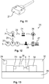
- Figure 12 shows the overall system for explaining the use of a control board 7 according to the invention.
- the control circuit board 7 is arranged in the tool holder 1 and establishes a data connection 25 with a tool 5 when this is inserted into the tool holder 1.
- the control board 7 reads out data via the data connection 25, for example process parameters and / or measurement data, and transmits them to the collector 21 via the radio interface 20.
- the collector 21 is connected to a cloud 26 and transmits the data there.
- the cloud 26 is accessible via a computer 27, which brings this data to a user 28 or to a controller 29 of a processing machine 30 (cf. Fig. 13 ), to which the tool holder 1 belongs, is transmitted.
- a control loop 31 is thus created. Data and commands can also be transmitted in the opposite direction here.
- Figure 13 shows a processing machine 30 with a tool holder 1 according to the invention, which carries a tool 5 according to the invention and which is mounted on a drive spindle 32.
- the drive spindle 32 stands on a machine bed 35 and defines a machining space 36.
- the collector 21 is arranged outside this processing space 36.
- the collector 21 communicates with the control board 7 in the tool 5 and with the controller 29.
- Figures 6 to 10 show a further exemplary embodiment according to the invention. Components and functional units that are structurally and / or functionally similar or identical to the preceding exemplary embodiment are provided with the same reference symbols and are not described again separately. The remarks on the Figures 1 to 5 and 11 to 13 apply to the Figures 6 to 10 corresponding.
- the exemplary embodiment differs from the preceding exemplary embodiment at least in that the tool holder has a steep taper 37.
Landscapes
- Engineering & Computer Science (AREA)
- Mechanical Engineering (AREA)
- Physics & Mathematics (AREA)
- Optics & Photonics (AREA)
- Machine Tool Sensing Apparatuses (AREA)
Abstract
Bei einem Werkzeughalter (1) wird vorgeschlagen, eine Steuerplatine (7) zum Datenaustausch mit einem eingesetzten Werkzeug (5) zu verwenden (Fig. 1).In the case of a tool holder (1), it is proposed to use a control board (7) for data exchange with an inserted tool (5) (FIG. 1).
Description
Die Erfindung betrifft eine Steuerplatine, welche insbesondere wenigstens einen Sensor und wenigstens ein Speichermedium enthält und/oder mit einer Funkschnittstelle ausgestattet ist, um einen Bearbeitungsprozess auf einer Bearbeitungsmaschine in Echtzeit zu überwachen.The invention relates to a control circuit board which in particular contains at least one sensor and at least one storage medium and / or is equipped with a radio interface in order to monitor a machining process on a machine tool in real time.
Derartige Steuerplatinen sind bekannt und werden beispielsweise in Steuerungen von Bearbeitungsmaschinen eingesetzt, um Daten eines Werkzeugs zu erfassen. Die Sensoren sind hierbei beispielsweise außerhalb der Steuerung angeordnet, beispielsweise um Kennungen an Werkzeugen optisch auslesen zu können.Such control boards are known and are used, for example, in controls of processing machines in order to acquire data from a tool. In this case, the sensors are arranged, for example, outside the control, for example in order to be able to optically read out identifiers on tools.
Die Erfindung betrifft weiter einen Werkzeughalter, ein Werkzeug, eine Verwendung einer Steuerplatine und eine Bearbeitungsmaschine.The invention further relates to a tool holder, a tool, a use of a control board and a processing machine.
Im Rahmen der zunehmenden Durchdringung von Industrie-4.0-Themen im Bereich der zerspanenden Bearbeitungsmaschinen, insbesondere Werkzeugmaschinen, ist die exakte Kenntnis über das in der Maschine arbeitende Zerspanungswerkzeug immer wichtiger. Durch das Werkzeug werden wichtige Prozessparameter wie z. B. die Drehzahl oder der Vorschub definiert, die zur spanenden Bearbeitung von Bauteilen notwendig sind.In the context of the increasing penetration of Industry 4.0 topics in the field of machining tools, especially machine tools, precise knowledge of the cutting tool working in the machine is becoming more and more important. Important process parameters such as B. defines the speed or the feed that are necessary for the machining of components.
Generell können Prozessdaten in zwei unterschiedliche Arten eingeteilt werden. Die erste Art von Daten kann der Werkzeughersteller mit jedem Werkzeug liefern. Dabei handelt es sich um maximale oder minimale Begrenzungswerte, die auch sicherheitsrelevant sein können. Auch können beschreibende Daten mitgeliefert werden. Hierbei ist z. B. das Gewicht, die Wuchtgüte oder unterschiedliche Abmessungen zu nennen. Insbesondere die geometrischen Abmessungen können direkt zur Bauteilbearbeitung im NC-Programm der Maschine verwendet werden. Zudem können empfohlene Einsatzdaten mitgegeben werden, wie z.B. Drehzahl (n), Vorschub (vf), Vorschub pro Zahn (fz) oder die Schnittgeschwindigkeit (vc). Diese Daten bilden die Basis für die zweite Art von Prozessparametern. Der Maschinenbediener hat die Aufgabe, den Zerspanungsprozess in der Maschine einzustellen. Hierbei werden die empfohlenen Einsatzdaten mit eigenen Erfahrungswerten abgeglichen und optimiert. Dabei ist es nicht unüblich, dass sich der Maschinenbediener auf sein Gehör verlässt, um die Zerspangeräusche zu bewerten. Zudem erfolgt eine optische Kontrolle der Schnittqualität. Sind die optimalen Parameter gefunden, finden in der Regel nur noch wenige Änderungen an den Prozessparametern statt. Auf Prozessschwankungen durch beispielsweise Materialeinflüsse oder Aufspannungssituationen kann kaum eingegangen werden. Insbesondere bei mannlosen Schichten fehlen Rückmeldungen an den Bediener. Die genannten Einsatzparameter können um Schwingungs- oder Temperaturmesswerte ergänzt werden. Durch diese Ergänzung besteht die Möglichkeit, dass sich die Anforderungen für die Einsatzdaten ändern. In vielen modernen Bearbeitungsmaschinen sind Spindelwächter integriert, die in der Regel nur im Extremfall in die Prozessbetrachtung einfließen. Als Beispiel ist die Resonanzkatastrophe zu nennen.In general, process data can be divided into two different types. The tool manufacturer can supply the first type of data with every tool. These are maximum or minimum limit values that can also be safety-relevant. Descriptive data can also be supplied. Here is z. B. to name the weight, the balance quality or different dimensions. In particular, the geometric dimensions can be used directly Component machining can be used in the NC program of the machine. In addition, recommended application data can be given, such as speed (n), feed (vf), feed per tooth (fz) or the cutting speed (vc). These data form the basis for the second type of process parameters. The machine operator is responsible for setting the machining process in the machine. The recommended application data are compared with your own experience and optimized. It is not uncommon for the machine operator to rely on his hearing to evaluate the cutting noises. In addition, the quality of the cut is visually checked. Once the optimal parameters have been found, there are usually only a few changes to the process parameters. Process fluctuations due to material influences or clamping situations, for example, can hardly be dealt with. There is no feedback to the operator, especially in the case of unmanned shifts. The application parameters mentioned can be supplemented by measured vibration or temperature values. With this addition, there is the possibility that the requirements for the operational data will change. Spindle monitors are integrated in many modern processing machines, which are usually only included in the process analysis in extreme cases. One example is the resonance catastrophe.
Dem Kunden eine Kombination von fixen Werkzeugparametern und dynamischen Messwerten zur Verfügung zu stellen, ist für die Werkzeughersteller äußerst schwierig. Für die Optimierung von Prozessen und zum optimalen Einsatz der Werkzeuge sind dynamische Messwerte allerdings notwendig. Zur Realisierung dieser Kombination ist bisher immer eine Kooperation mit dem Maschinen- oder Anlagenhersteller erforderlich. Die Vielzahl der Maschinenhersteller und die Anzahl unterschiedlicher Standards erschweren eine effektive Gestaltung von Entwicklungsprojekten und ebenso eine gute Marktdurchdringung für erarbeitete Konzepte. Aus der Sicht der Hersteller von Zerspanungsmaschinen sieht es nicht anders aus. Bei dem eindeutigen Identifizieren des Werkzeugs sind die Maschinenhersteller auf die Werkzeughersteller angewiesen. Zum Stand der Technik zählt eine Reihe von adaptiven Systemen, welche auf die Integration in die Maschinensteuerungen angewiesen sind. Ein Nachrüsten älterer Maschinen ist häufig nicht machbar oder unwirtschaftlich. Hinzu kommt, dass das Auslesen von Werkzeugdaten vom Werkzeug direkt oder durch Auslesen einer Werkzeugkennung vom Werkzeug nur in wenigen Fällen umgesetzt werden kann. In der Regel kann diese Eigenschaft bei Spezialmaschinen z. B. Sägemaschinen ohne Werkzeugwechsler realisiert werden. Die genannten Gründe tragen dazu bei, dass sich diese Technologie insbesondere bei CNC-Fräsmaschinen nicht durchsetzen konnte.Providing the customer with a combination of fixed tool parameters and dynamic measured values is extremely difficult for tool manufacturers. However, dynamic measured values are necessary for the optimization of processes and for the optimal use of the tools. To implement this combination, it has always been necessary to cooperate with the machine or system manufacturer. The large number of machine manufacturers and the number of different standards make it difficult to design development projects effectively and to achieve good market penetration for developed concepts. From the perspective of the manufacturers of cutting machines, it looks no different. The machine manufacturers are dependent on the tool manufacturer for the unambiguous identification of the tool. The state of the art includes a number of adaptive systems that are dependent on integration into the machine controls. Retrofitting older machines is often not feasible or uneconomical. In addition, reading out tool data from the tool directly or by reading out a tool identifier from the tool can only be implemented in a few cases. As a rule, this property can be used in special machines such. B. sawing machines can be realized without a tool changer. The reasons mentioned contribute to the fact that this technology could not prevail, especially with CNC milling machines.
Ein weiterer und sehr wichtiger Aspekt der Werkzeugoptimierung aus Sicht der Werkzeughersteller ist die Möglichkeit, durch das Gewinnen von echten Prozessdaten eine weitere Optimierung der Werkzeuge durchführen zu können. Mit Zustimmung des Kunden wäre der Werkzeughersteller in der Lage, die gewonnenen Prozessdaten der Produkte in die Produktentwicklung einfließen zu lassen. So kann nicht nur die time-to-market verkürzt werden. Wesentlich ist auch eine ressourcenschonende Entwicklung durchzuführen. Auf dem Weg zum marktreifen Produkt kann der Werkzeughersteller mit weniger Prototypen das Ziel erreichen.Another and very important aspect of tool optimization from the tool manufacturer's point of view is the possibility of further optimizing the tools by obtaining real process data. With the customer's consent, the tool manufacturer would be able to incorporate the process data obtained from the products into product development. This not only shortens the time-to-market. Resource-saving development is also essential. On the way to a market-ready product, the tool manufacturer can achieve the goal with fewer prototypes.
Aus der beschriebenen Situation definiert sich folgende Aufgabe für die Werkzeughersteller mit dem Blick auf eine autarke Lösung bei der Prozessoptimierung beim Kunden: Gesucht ist ein System und ein Produkt, dass die werkzeugrelevanten Daten aus dem eindeutig identifizierten Werkzeug auslesen kann und diese mit Prozessmesswerten kombiniert ohne einen zwingend notwendigen Zugriff auf die Maschinensteuerung zu haben. Auf dieser Basis soll dem Maschinenbediener oder der Maschine oder Anlage eine Unterstützung bei der Prozessoptimierung oder bei der Reaktion auf prozessbedingte Schwankungen gegeben werden. Im einfachsten Fall soll dem Maschinenbediener oder der Maschine oder Anlage die Möglichkeit gegeben werden, das aktive Werkzeug eindeutig zu erkennen. Zudem muss das System oder Produkt bei CNC Fräsmaschinen mit Werkzeugwechsler mühelos funktionieren. Damit eine gute Marktdurchdringung erzielt werden kann, ergänzt sich die Aufgabe durch die Notwendigkeit, dass der Kunde in der Lage sein muss, das System oder Produkt auf älteren, bestehenden Maschinen nutzen zu können, ohne diese verändern zu müssen. Im Sinne des Industrie-4.0-Gedankens ist ein offenes System gefordert, dass auf IoT Basis kommunizieren kann.From the situation described, the following task is defined for the tool manufacturer with a view to a self-sufficient solution for process optimization at the customer's: What is needed is a system and a product that can read out the tool-relevant data from the clearly identified tool and combine this with process measured values without one absolutely necessary access to the machine control. On On this basis, the machine operator or the machine or system should be given support in process optimization or in responding to process-related fluctuations. In the simplest case, the machine operator or the machine or system should be given the opportunity to clearly identify the active tool. In addition, the system or product must work effortlessly on CNC milling machines with tool changers. In order to achieve good market penetration, the task is supplemented by the need for the customer to be able to use the system or product on older, existing machines without having to change them. In terms of Industry 4.0, an open system is required that can communicate on an IoT basis.
Zur Lösung der Aufgabe sind bei einer Steuerplatine erfindungsgemäß die Merkmale des Anspruchs 1 vorgesehen. Insbesondere ist somit erfindungsgemäß bei einer Steuerplatine zur Lösung der Aufgabe vorgesehen, dass die Steuerplatine in einen Werkzeughalter oder eine Werkzeugaufnahme einbringbar oder eingebracht ist, wobei die Steuerplatine im eingebauten Zustand und während des Betriebs einer Bearbeitungsmaschine Prozess- und Messdaten, von einem in dem Werkzeughalter montierten Werkzeug lesen kann.To achieve the object, the features of
Insbesondere kann hierbei vorgesehen sein, dass die Steuerplatine wenigstens einen Sensor und wenigstens ein Speichermedium enthält. Alternativ oder zusätzlich kann vorgesehen sein, dass die Steuerplatine mit einer Funkschnittstelle ausgestattet ist, um einen Bearbeitungsprozess auf einer Bearbeitungsmaschine in Echtzeit zu überwachen.In particular, it can be provided here that the control board contains at least one sensor and at least one storage medium. Alternatively or additionally, it can be provided that the control board is equipped with a radio interface in order to monitor a machining process on a machine tool in real time.
Alternativ oder zusätzlich kann zur Lösung der genannten Aufgabe vorgesehen sein, dass die Steuerplatine im eingebauten Zustand und während des Betriebs einer Bearbeitungsmaschine Prozess- und Messdaten auf ein in dem Werkzeughalter montiertes Werkzeug schreiben kann. Somit können beispielsweise Daten über den Einsatz, die Einsatzart, die Einsatzbelastung und/oder die Einsatzdauer auf einfache Weise in dem Werkzeug hinterlegt und bei späteren Einsätzen weiterverwendet werden.As an alternative or in addition, it can be provided to solve the stated problem that the control board is built-in State and during the operation of a processing machine can write process and measurement data on a tool mounted in the tool holder. Thus, for example, data on the use, the type of use, the workload and / or the duration of use can be stored in the tool in a simple manner and used further in later uses.
Die Erfindung bietet somit die Möglichkeit, eine sensorische Steuerplatine bereitzustellen, deren Geometrie so ausgelegt ist, dass sie in einen Werkzeughalter montiert werden kann. Die Erfindung ermöglicht somit, dass die Steuerplatine in dem Werkzeughalter eine Schnittstelle zwischen Werkzeug und Maschinenbediener bildet. Eine Integration in die Bearbeitungsmaschine bzw. deren Steuerung ist somit nicht zwingend erforderlich. Vielmehr kann vorgesehen sein, dass die sensorische Steuerplatine Werkzeugdaten im eingebauten Zustand und während des Betriebs der Bearbeitungsmaschine Prozess- und Messdaten von dem in dem Werkzeughalter montierten Werkzeug liest und diese Daten über eine drahtlose Verbindung weitergibt.The invention thus offers the possibility of providing a sensory control board, the geometry of which is designed so that it can be mounted in a tool holder. The invention thus enables the control board in the tool holder to form an interface between the tool and the machine operator. An integration into the processing machine or its control is therefore not absolutely necessary. Rather, it can be provided that the sensor-based control board reads tool data in the installed state and during operation of the processing machine, process and measurement data from the tool mounted in the tool holder and forwards this data via a wireless connection.
Es ist somit die Implementierung einer Lese- und/oder Schreibeinheit in einen Werkzeughalter realisierbar. Um diese zu realisieren, kann die Lese- und/oder Schreibeinheit in eine oder mehrere miteinander verbundene Steuerplatinen integriert sein. Die Steuerplatine(n) kann/können Sensoren besitzen, um Prozessdaten zu erfassen. Diese Steuerplatine kann beispielsweise Daten vom Werkzeug lesen und ggf. wieder auf das Werkzeug schreiben. Dazu kann das Werkzeug mit einem Speicherchip ausgestattet sein. In einigen Fällen (je nach Technologie) ist ein physikalischer, kurzzeitiger Kontakt zwischen dem Speicherchip des Werkzeugs und der Steuerplatine zum Lesen und Schreiben der Daten notwendig. Hierfür könnte die Steuerplatine wenigstens einen entsprechenden Gegenkontakt bieten. Es hat sich herausgestellt, dass die ideale Position der Kontakte mittig im inneren des Werkzeughalters ist. Auf der Steuerplatine können Werkzeugdaten eines Speicherchips von einem Werkzeug und Messwerte der Sensoren der Steuerplatine selbst oder eines Werkzeugs verarbeitet werden. Zudem kann die Steuerplatine über eine drahtlose Verbindung z. B. Bluetooth, WLAN, Zigbee, NFC mit einem Kollektor kommunizieren, der wiederum die Daten an ein Netzwerk weiterleiten kann. Es ist auch möglich, dass die Steuerplatine direkt mit einem mobilen Endgerät kommuniziert. Damit die Steuerplatine im Werkzeughalter autark arbeiten kann, ist eine Energiequelle von Vorteil. Außerdem bedarf es unter Umständen Abstandshaltern für die einzelnen Steuerplatinen, sowie Haltern für die Energiequelle, als auch einem Verschlussdeckel der die einzelnen Komponenten an einer Stelle fixiert. Diese Gesamteinheit, im weiteren als Steuerplatine bezeichnet, muss im Werkzeughalter Platz finden.It is thus possible to implement a read and / or write unit in a tool holder. In order to implement this, the reading and / or writing unit can be integrated in one or more interconnected control boards. The control board (s) can have sensors to record process data. This control board can, for example, read data from the tool and, if necessary, write it back to the tool. For this purpose, the tool can be equipped with a memory chip. In some cases (depending on the technology) a physical, short-term contact between the memory chip of the tool and the control board is necessary for reading and writing the data. For this purpose, the control board could have at least one corresponding mating contact Offer. It has been found that the ideal position of the contacts is in the center of the inside of the tool holder. Tool data from a memory chip from a tool and measured values from the sensors on the control board itself or from a tool can be processed on the control board. In addition, the control board can be connected via a wireless connection, for. B. Bluetooth, WLAN, Zigbee, NFC communicate with a collector, which in turn can forward the data to a network. It is also possible for the control board to communicate directly with a mobile device. An energy source is an advantage so that the control board in the tool holder can work independently. In addition, spacers may be required for the individual control boards, as well as holders for the energy source, as well as a cover that fixes the individual components in one place. This complete unit, hereinafter referred to as the control board, must find space in the tool holder.
Eine Integration in die Maschinensteuerung ist möglich, wichtiger ist allerdings, dass diese Integration nicht notwendig ist.Integration into the machine control is possible, but what is more important is that this integration is not necessary.
Durch diesen Lösungsansatz ist der Werkzeughersteller in der Lage, dem Kunden einen Mehrwert zu liefern. Der Mehrwert besteht nicht nur in der gezielten Prozessoptimierung durch die Kombination aus mitgelieferten Werkzeugdaten und der Verarbeitung von gemessenen Prozessdaten, sondern auch in dem einfachen Auslesen der Werkzeugdaten. Zudem können Meldungen wie Alarme, Hinweise und Empfehlungen an den Bediener übermittelt werden.With this approach, the tool manufacturer is able to deliver added value to the customer. The added value consists not only in the targeted process optimization through the combination of the supplied tool data and the processing of measured process data, but also in the simple readout of the tool data. In addition, messages such as alarms, notes and recommendations can be sent to the operator.
Der Werkzeughalter fällt in das Produktportfolio des Werkzeugherstellers. Dadurch können das Werkzeug mit den Daten, der Werkzeughalter mit der Steuerplatine und die Prozessoptimierung als System und Produkt im Markt maschinenunabhängig angeboten werden.The tool holder is part of the tool manufacturer's product portfolio. This allows the tool with the data, the tool holder with the control board and the Process optimization as a system and product can be offered on the market independently of the machine.
Hierdurch ist der Werkzeughersteller in der Lage, ein Gesamtsystem an Kunden auszuliefern, ohne auf Systemkomponenten angewiesen zu sein, die nicht im direkten Einfluss stehen. Weder ein Computer noch ein Lesegerät muss vom Kunden zwingend zur Verfügung gestellt werden.This enables the tool manufacturer to deliver a complete system to customers without having to rely on system components that are not directly influenced. Neither a computer nor a reader must be made available by the customer.
Beispielsweise kann für eine Cloud-basierte Kommunikation eine Verbindung zum Internet aufbaubar oder bereitgestellt sein, wobei auch diese mitgeliefert werden kann. Zeitgemäß ist auch die Verwendung von mobilen Endgeräten zur Mensch-Maschine-Kommunikation bzw. zur Mensch-Werkzeug-Kommunikation. Hierdurch können auch Kunden bedient werden, die Ihre Daten nicht außerhalb Ihres Unternehmens speichern möchten. Eine problemlose Integration des Industrie-4.0-Gedankens auf Maschinen mit älteren Steuerungen ist machbar.For example, a connection to the Internet can be established or provided for cloud-based communication, and this can also be supplied. The use of mobile devices for human-machine communication or for human-tool communication is also up-to-date. This also enables customers to be served who do not want to save their data outside of their company. A problem-free integration of the Industry 4.0 concept on machines with older controls is feasible.
Durch die Systemarchitektur (Steuerplatine/Kollektor) ist eine Kommunikation mit vielen Maschinen bzw. Werkzeughaltern machbar und wünschenswert. Hierbei ist es unerheblich, ob der Kollektor direkt mit der PLC (Maschinensteuerung) oder einem Leitrechner bzw. Bedienterminal kommuniziert.The system architecture (control board / collector) means that communication with many machines or tool holders is feasible and desirable. It is irrelevant here whether the collector communicates directly with the PLC (machine control) or a master computer or operator terminal.
Bei den Werkzeughaltern im Bereich der CNC-Fräsen hat sich die Verwendung von HSK-Schnittstellen (HSK=Hohlschaftkegel) durchgesetzt. Zu einer HSK-Schnittstelle gehört der Kegel, ein Anlagebund und die Greifer-Rille. Diese HSK-Schnittstellen sind, je nach Anforderungen, in unterschiedlichen Ausführungen verfügbar. Dabei variieren im Wesentlichen die Größe des Kegels und der Durchmesser der Anlagefläche. Die Größe des Kegels ist für die Erfindung der wichtigere Aspekt. Da alle Hohlschaftkegel mit einem Steigungsverhältnis von ca. 1:10 gefertigt werden, ist der Innendurchmesser für die Implementierung von besonderer Bedeutung. Die Montage der Platine kann durch diesen Innendurchmesser geschehen. Das bedeutet, der Innendurchmesser definiert den maximalen Durchmesser der Platine und der Energiequelle. Der aktuelle Stand der Technik bei der Batterieentwicklung lässt einen Einsatz in einem HSK-Werkzeughalter mit einer Kegelgröße zu, die z. B. in dem HSK50E oder im HSK63F Verwendung findet ohne eine geometrische Veränderung der äußeren Abmessungen vorzunehmen. Für kleinere Kegel ist die Integration generell möglich, allerdings ist eine geometrische Verlängerung der Werkzeugaufnahme nötig. Neben der HSK-Schnittstelle ist auch, insbesondere bei älteren Maschinen eine SK-Schnittstelle (SK=Steilkegel) weit verbreitet. Auch hier kann eine Platine mit anderer Bauform und anderer Energiequelle eingebracht werden. Aufgrund der langen Bauform des Kegels kann die Steuerplatine hier in die wesentlich kleinere Öffnung verbaut werden. Bei fast allen Maschinen ist es notwendig, in diese Öffnung den Einzugsbolzen einzuschrauben. Diese Möglichkeit besteht nach wie vor.The use of HSK interfaces (HSK = hollow tapered shank) has established itself among tool holders in the field of CNC milling. An HSK interface includes the cone, a contact collar and the gripper groove. These HSK interfaces are available in different versions depending on the requirements. The size of the cone and the diameter of the contact surface essentially vary. The size of the cone is the more important aspect for the invention. Since all hollow taper shanks are manufactured with a pitch ratio of approx. 1:10, the inside diameter for the Implementation of particular importance. The assembly of the circuit board can be done through this inner diameter. This means that the inner diameter defines the maximum diameter of the circuit board and the energy source. The current state of the art in battery development allows use in an HSK tool holder with a cone size that e.g. B. in the HSK50E or in the HSK63F is used without making a geometric change to the external dimensions. Integration is generally possible for smaller cones, but a geometrical extension of the tool holder is necessary. In addition to the HSK interface, an SK interface (SK = steep taper) is also widespread, especially on older machines. Here, too, a circuit board with a different design and a different energy source can be inserted. Due to the long design of the cone, the control board can be installed in the much smaller opening. With almost all machines it is necessary to screw the draw-in bolt into this opening. This possibility still exists.
Es sei darauf hingewiesen, dass die derzeitige Kühlmitteldurchführung durch das Zentrum des Halters insbesondere bei HSK-Schnittstellen nicht in jedem Fall möglich ist. Es gibt Elemente auf der Steuerplatine, die Ihre physikalischen Eigenschaften optimal im Zentrum des Halters ausspielen können. Eine Durchleitung von Kühlmittel ist allerdings nach wie vor möglich.It should be noted that the current coolant lead-through through the center of the holder is not always possible, especially with HSK interfaces. There are elements on the control board that can optimally display their physical properties in the center of the holder. A passage of coolant is still possible, however.
Die Position der Antenne und einer Kontrollleuchte ist für die Funktion der Steuerplatine ebenso notwendig. Es hat sich herausgestellt, dass eine ideale Position für die Antenne direkt am Bund der Greiferrille auf der Werkzeugseite ist. Hier kann das Kabel für die Antenne sinnvoll durchgeführt werden, zudem wird von hier aus eine große Reichweite erzielt. Die Antenne wird vorzugsweise mit einer Kunststoffabdeckung geschützt. Zudem kann auf gleiche Weise eine Signalleuchte in Form einer LED angebracht werden. Um die optische Rückmeldung durch die LED für den Bediener sichtbar zu machen, kann das Gehäuse aus lichtdurchlässigem Material bestehen. Auf diese Weise kann die LED vor Beschädigungen durch Staub oder Kühlschmierstoff geschützt werden.The position of the antenna and a control lamp is also necessary for the function of the control board. It has been found that an ideal position for the antenna is directly on the collar of the gripper groove on the tool side. The cable for the antenna can be routed here sensibly, and a large range is also achieved from here. The antenna is preferably covered with a plastic cover protected. In addition, a signal light in the form of an LED can be attached in the same way. In order to make the optical feedback from the LED visible to the operator, the housing can be made of translucent material. In this way, the LED can be protected from damage by dust or cooling lubricant.
Der Werkzeughalter muss so gestaltet sein, dass er die Platine vor Staub und Kühlschmierstoff schützt.The tool holder must be designed in such a way that it protects the circuit board from dust and cooling lubricant.
In CNC-Fräsmaschinen wird häufig mit Aggregaten gearbeitet, die unterschiedliche Aufgaben erfüllen. In vielen Fällen werden in die Aggregate, ebenso wie bei den Werkzeughaltern, Werkzeuge eingebaut. Auch bei diesen Anwendungen kann die vorliegende Erfindung Verwendung finden. Bauartbedingt ist es hier jedoch nicht zwingend erforderlich, dass die Steuerplatine durch den HSK eingebaut wird. Auf dem Gehäuse der Aggregate finden sich einige, ideale Stellen zur Positionierung der Steuerplatine. Viele Aggregate beinhalten ein Getriebe, welches die Situation zum Auslesen der Werkzeuge verändert. Die beschriebene Position im Inneren der Werkzeugaufnahme ist häufig nicht machbar. Die Steuerplatine kann in einem eigenen Gehäuse außen auf das Aggregatgehäuse befestigt werden. Das Gehäuse der Steuerplatine kann Kontakte enthalten, mit denen die Werkzeuge gelesen und beschrieben werden können. Durch diese Methode wird das Grundprinzip der Lösung, und damit der Erfindung nicht verändert.CNC milling machines often work with units that perform different tasks. In many cases, tools are built into the units, as is the case with the tool holders. The present invention can also be used in these applications. Due to the design, however, it is not absolutely necessary for the control board to be installed by the HSK. On the housing of the units there are some ideal places for positioning the control board. Many units contain a gearbox that changes the situation for reading out the tools. The described position inside the tool holder is often not feasible. The control board can be attached to the outside of the unit housing in its own housing. The housing of the control board can contain contacts with which the tools can be read and written. This method does not change the basic principle of the solution, and thus of the invention.
Werkzeughalter und Aggregate kommen nicht nur in Werkzeugaufnahmen für CNC-Fräsmaschinen zum Einsatz. Zur Aufnahme von Werkzeugen mit zentrischer Aufnahmebohrung wie z.B. Kreissägeblätter, Fräswerkzeuge auf stationären Maschinen werden einfache Buchsen oder Flansche mit Spanndeckel verwendet. Die Erfindung kann auch in dieser Art von Werkzeugaufnahme und Spanndeckel integriert werden. Bei diesen Werkzeugaufnahmen stellt sich die Integration der Steuerplatine aufgrund der Bauweise der Aufnahmen weniger problematisch dar. Dadurch ist die Technologie in nahezu allen Bereichen der Zerspanenden-Industrie verwendbar. Auch hier können die Kontakte so angebracht sein, dass die Daten des Werkzeugs im eingebauten Zustand gelesen und geschrieben werden können.Tool holders and units are not only used in tool holders for CNC milling machines. Simple sockets or flanges with clamping covers are used to accommodate tools with a central mounting hole such as circular saw blades and milling tools on stationary machines. The invention can also be integrated in this type of tool holder and clamping cover. With these The integration of the control board is less of a problem for tool holders due to the design of the holders. This means that the technology can be used in almost all areas of the machining industry. Here, too, the contacts can be attached in such a way that the data of the tool can be read and written in the installed state.
Bei einer Ausgestaltung der Erfindung kann vorgesehen sein, dass die Steuerplatine durch ihre Bauform von einer der Antriebsspindel zugewandten Seite her, beispielsweise in einen Hohlschaftkegel oder Steilkegel des Werkzeughalters, eingesetzt werden kann. Somit ist eine einfache Wartung und/oder Nachrüstung möglich.In one embodiment of the invention, it can be provided that the design of the control board can be inserted from a side facing the drive spindle, for example into a hollow shank taper or steep taper of the tool holder. Simple maintenance and / or retrofitting is thus possible.
Bei einer Ausgestaltung der Erfindung kann vorgesehen sein, dass die Steuerplatine bezogen auf die Rotationsachse des Werkzeughalters einen mittigen Kontakt zur Verbindung mit dem montierten Werkzeug hat oder beim Einbau vorübergehend Kontakt herstellen kann. Somit ist das Werkzeug in beliebiger Orientierung kontaktierbar.In one embodiment of the invention, it can be provided that the control board has a central contact with respect to the axis of rotation of the tool holder for connection to the mounted tool or can make temporary contact during installation. The tool can thus be contacted in any orientation.
Bei einer Ausgestaltung der Erfindung kann vorgesehen sein, dass die Steuerplatine im eingebauten Zustand und während des Betriebs der Bearbeitungsmaschine Werkzeugdaten vom Werkzeug lesen kann und/oder auf das Werkzeug schreiben kann. Von Vorteil ist dabei, dass ein Regelkreis bildbar ist und dass Stillstandszeiten für eine Parametrierung der Bearbeitungsmaschine vermeidbar oder reduzierbar sind. Insbesondere kann hierbei vorgesehen sein, dass die Werkzeugdaten Vorgabewerte für den Einsatz und/oder Messwerte aus dem Einsatz umfassen.In one embodiment of the invention, it can be provided that the control board can read tool data from the tool and / or write to the tool in the installed state and during operation of the processing machine. The advantage here is that a control loop can be formed and that downtimes for parameterizing the processing machine can be avoided or reduced. In particular, it can be provided here that the tool data include default values for the use and / or measured values from the use.
Bei einer Ausgestaltung der Erfindung kann vorgesehen sein, dass die Steuerplatine die Daten mittels einer auf einer Außenhülle des Werkzeughalters angebrachten Antenne kommuniziert. Somit ist eine gute Signalabstrahlung erreichbar. Beispielsweise kann hierbei vorgesehen sein, dass die Antenne unmittelbar unterhalb der Greiferrille und/oder unter einer ringförmigen Schutzabdeckung angebracht ist. Somit ist ein Platzverbrauch gering haltbar und/oder es ist eine Beschädigung oder Verschmutzung der Antenne vermeidbar.In one embodiment of the invention, it can be provided that the control board receives the data by means of an on a Outer shell of the tool holder attached antenna communicates. Good signal radiation can thus be achieved. For example, it can be provided here that the antenna is attached directly below the gripper groove and / or under an annular protective cover. Thus, the space consumption can be kept low and / or damage to or contamination of the antenna can be avoided.
Bei einer Ausgestaltung der Erfindung kann vorgesehen sein, dass die Steuerplatine in der Lage ist, mit IoT-Systemen und Komponenten solcher Systeme zu kommunizieren. Somit sind Regelkreis bildbar und Daten einfach verwaltbar.In one embodiment of the invention it can be provided that the control board is able to communicate with IoT systems and components of such systems. This means that control loops can be created and data can be easily managed.
Bei einer Ausgestaltung der Erfindung kann vorgesehen sein, dass die Steuerplatine als Bestandteil eines Regelkreises integriert werden und Daten im Prozess aufnehmen und bereitstellen kann. Somit sind Eigenschaften des Werkzeugs einfach einspeisbar in einen Regelkreis.In one embodiment of the invention, it can be provided that the control board is integrated as part of a control loop and can record and provide data in the process. This means that the properties of the tool can easily be fed into a control loop.
Bei einer Ausgestaltung der Erfindung kann vorgesehen sein, dass die Steuerplatine im Werkzeughalter gewartet werden kann oder falls erforderlich, aufgrund ihrer Einbauart auch nachträglich ausgetauscht, werden kann. Somit ist eine Veränderung des Werkzeughalters vermeidbar.In one embodiment of the invention, it can be provided that the control circuit board in the tool holder can be serviced or, if necessary, can also be subsequently exchanged due to its type of installation. A change in the tool holder can thus be avoided.
Bei einer Ausgestaltung der Erfindung kann vorgesehen sein, dass eine Energiequelle, beispielsweise eine Batterie, der Steuerplatine im Werkzeughalter angeordnet ist. Somit ist die Steuerplatine an einem drehenden Teil autark betreibbar. Bevorzugt kann die Energiequelle ausgetauscht werden ohne die Steuerplatine zu entfernen.In one embodiment of the invention it can be provided that an energy source, for example a battery, of the control board is arranged in the tool holder. The control board can thus be operated independently on a rotating part. The energy source can preferably be exchanged without removing the control board.
Zur Lösung der genannten Aufgabe wird weiter ein Werkzeughalter mit einer erfindungsgemäßen Steuerplatine, insbesondere wie zuvor beschrieben und/oder nach einem der auf eine Steuerplatine gerichteten Ansprüche, vorgeschlagen.To achieve the stated object, a tool holder with a control board according to the invention is also in particular as described above and / or according to one of the claims directed to a control board, proposed.
Bei einer Ausgestaltung der Erfindung kann vorgesehen sein, dass die Steuerplatine in einer Bohrung angeordnet ist. Hierbei kann vorgesehen sein, dass wenigstens ein Kontakt der Steuerplatine in eine Werkzeugaufnahme des Werkzeughalters ragt. Es ist somit eine einfache galvanische Ankopplung zur Ausbildung einer Datenverbindung zwischen der Steuerplatine und dem Werkzeug erreichbar. Beispielsweise kann die Steuerplatine in einer Axialbohrung angeordnet sein.In one embodiment of the invention it can be provided that the control board is arranged in a bore. It can be provided here that at least one contact of the control board protrudes into a tool receptacle of the tool holder. A simple galvanic coupling for establishing a data connection between the control board and the tool can thus be achieved. For example, the control board can be arranged in an axial bore.
Bei einer Ausgestaltung der Erfindung kann vorgesehen sein, dass in dem Werkzeughalter eine Energiequelle für die Steuerplatine angeordnet ist. Somit ist die Steuerplatine autark betreibbar.In one embodiment of the invention it can be provided that an energy source for the control board is arranged in the tool holder. The control board can thus be operated independently.
Bei einer Ausgestaltung der Erfindung kann vorgesehen sein, dass an einer Außenhülle des Werkzeughalters eine Antenne ausgebildet ist, die mit der Steuerplatine zur Ausbildung einer Funkschnittstelle elektrisch verbunden ist. Es sind somit Daten nach außen übertragbar. Beispielsweise kann die Antenne unmittelbar unterhalb einer Greiferrille sein. Es kann auch vorgesehen sein, dass die Antenne unter einer ringförmigen Schutzabdeckung ausgebildet ist. Somit kann die Antenne geschützt angeordnet werden.In one embodiment of the invention, it can be provided that an antenna is formed on an outer shell of the tool holder, which antenna is electrically connected to the control board to form a radio interface. This means that data can be transferred to the outside world. For example, the antenna can be directly below a gripper groove. It can also be provided that the antenna is formed under an annular protective cover. The antenna can thus be arranged in a protected manner.
Zur Lösung der genannten Aufgabe ist bei einem Werkzeug erfindungsgemäß vorgesehen, dass das Werkzeug von einem Werkzeughalter mit einer erfindungsgemäßen Steuerplatine, insbesondere wie zuvor beschrieben und/oder nach einem der auf eine Steuerplatine gerichteten Ansprüche, aufgenommen werden kann und dass das Werkzeug mit einem elektronisch auslesbaren Speichermedium ausgerüstet und/oder mit wenigstens einem Sensor, insbesondere mehreren Sensoren, ausgestattet ist, um im eingebauten Zustand und während des Einsatzes Daten, insbesondere Prozesskennwerte und Messdaten aufzunehmen und an die Steuerplatine weiterzugeben. Somit sind Daten vom Werkzeug, beispielsweise aus einem Speichermedium oder von Sensoren, einfach auslesbar.In order to achieve the stated object, the invention provides for a tool that the tool can be received by a tool holder with a control board according to the invention, in particular as described above and / or according to one of the claims directed to a control board, and that the tool can be read with an electronically readable Storage medium equipped and / or equipped with at least one sensor, in particular several sensors, to In the installed state and during use, record data, in particular process parameters and measurement data, and pass them on to the control board. This means that data from the tool, for example from a storage medium or from sensors, can be easily read out.
Bei einer vorteilhaften Ausgestaltung kann vorgesehen sein, dass das Speichermedium und/oder der wenigstens eine Sensor mit wenigstens einem Gegenkontakt verbunden ist/sind, die in einem zur Aufnahme in dem Werkzeughalter eingerichteten Befestigungsabschnitt des Werkzeugs angeordnet sind. Somit ist eine einfache galvanische Datenübertragung realisierbar. Die Datenübertragung ist automatisch beim Einsetzen des Werkzeugs herstellbar.In an advantageous embodiment, it can be provided that the storage medium and / or the at least one sensor is / are connected to at least one mating contact, which are arranged in a fastening section of the tool which is designed to be received in the tool holder. A simple galvanic data transmission can thus be realized. The data transfer can be established automatically when the tool is inserted.
Zur Lösung der genannten Aufgabe wird eine Verwendung einer Steuerplatine, beispielsweise einer erfindungsgemäßen Steuerplatine, insbesondere wie zuvor beschrieben und/oder nach einem der auf eine Steuerplatine gerichteten Ansprüche, in einem erfindungsgemäßen Werkzeughalter, insbesondere in einem Werkzeughalter wie zuvor beschrieben und/oder nach einem der auf einen Werkzeughalter gerichteten Ansprüche, zum Auslesen von an einem in den Werkzeughalter eingesetzten erfindungsgemäßen Werkzeug, insbesondere einem Werkzeug nach einem der auf ein Werkzeug gerichteten Ansprüche, bereitgestellten Daten vorgeschlagen.To achieve the stated object, use of a control board, for example a control board according to the invention, in particular as described above and / or according to one of the claims directed to a control board, in a tool holder according to the invention, in particular in a tool holder as described above and / or according to one of the Claims directed to a tool holder, proposed for reading out data provided on a tool according to the invention inserted in the tool holder, in particular a tool according to one of the claims directed to a tool.
Hierbei kann vorgesehen sein, dass die Steuerplatine die ausgelesenen Daten über eine Funkschnittstelle abgibt und/oder empfängt. Es ist somit eine Übermittlung an eine Vielzahl von Empfängern durchführbar.It can be provided here that the control board emits and / or receives the data read out via a radio interface. A transmission to a large number of recipients can thus be carried out.
Die Erfindung wird nun anhand von Ausführungsbeispielen näher erläutert, ist jedoch nicht auf diese Ausführungsbeispiele beschränkt. Weitere Ausführungsbeispiele ergeben sich durch Kombination der Merkmale einzelner oder mehrerer Schutzansprüche untereinander und/oder mit einzelnen oder mehreren Merkmalen der Ausführungsbeispiele.The invention will now be explained in more detail on the basis of exemplary embodiments, but is not limited to these exemplary embodiments. Further exemplary embodiments result from Combination of the features of one or more claims with one another and / or with one or more features of the exemplary embodiments.
Es zeigt:
- Fig. 1
- einen erfindungsgemäßen Werkzeughalter mit einem erfindungsgemäßen Werkzeug in einer Explosionsdarstellung von der Seite,
- Fig. 2
- den
Werkzeughalter aus Figur 1 zusammengesetzt/ zusammengebaut in einem Axialschnitt, - Fig. 3
- ein vergrößertes
Detail aus Figur 2 , denWerkzeughalter aus Figur 1 in einem Axialschnitt, - Fig. 4
- einen Blick auf die Werkzeug-abgewandte Seite des Werkzeughalters aus
Figur 1 , - Fig. 5
- einen Blick auf die Werkzeug-zugewandte Seite des Werkzeughalters aus
Figur 1 , - Fig. 6
- einen weiteren erfindungsgemäßen Werkzeughalter in einer Ansicht von der Seite,
- Fig. 7
- den
Werkzeughalter aus Figur 6 in einem Axialschnitt, - Fig. 8
- einen Blick auf die Werkzeug-abgewandte Seite des Werkzeughalters aus
Figur 6 , - Fig. 9
- einen Blick auf die Werkzeug-zugewandte Seite des Werkzeughalters aus
Figur 6 , - Fig. 10
- eine
Detailansicht aus Figur 7 , - Fig. 11
- eine dreidimensionale Schrägansicht auf einen Kollektor,
- Fig. 12
- eine Prinzipskizze eines Gesamtsystems für eine erfindungsgemäße Verwendung und
- Fig. 13
- eine schematische Darstellung einer erfindungsgemäßen Bearbeitungsmaschine.
- Fig. 1
- a tool holder according to the invention with a tool according to the invention in an exploded view from the side,
- Fig. 2
- the tool holder
Figure 1 assembled / assembled in an axial section, - Fig. 3
- an enlarged detail
Figure 2 , the tool holderFigure 1 in an axial section, - Fig. 4
- take a look at the side of the tool holder facing away from the tool
Figure 1 , - Fig. 5
- take a look at the tool-facing side of the tool holder
Figure 1 , - Fig. 6
- another tool holder according to the invention in a view from the side,
- Fig. 7
- the tool holder
Figure 6 in an axial section, - Fig. 8
- take a look at the side of the tool holder facing away from the tool
Figure 6 , - Fig. 9
- take a look at the tool-facing side of the tool holder
Figure 6 , - Fig. 10
- a detailed view
Figure 7 , - Fig. 11
- a three-dimensional oblique view of a collector,
- Fig. 12
- a schematic diagram of an overall system for use according to the invention and
- Fig. 13
- a schematic representation of a processing machine according to the invention.
Der Werkzeughalter 1 hat in bekannter Weise eine Spannzange 3, die in eine Werkzeugaufnahme 4 für ein Werkzeug 5 einsetzbar ist. Eine Spannmutter 6 dient zum Klemmen des Werkzeugs 5 in der Werkzeugaufnahme 4.In a known manner, the
In die Werkzeugaufnahme 4 ist wenigstens eine Steuerplatine 7 eingesetzt, vgl.
An der Steuerplatine 7 ist wenigstens ein Kontakt 9 ausgebildet, der in die Werkzeugaufnahme 4 so hineinragt, dass ihn ein Werkzeug 5, das in die Werkzeugaufnahme 4 eingesetzt wird, kontaktiert.At least one
Die Steuerplatine 7 ist so eingerichtet, dass Daten über den wenigstens einen Kontakt 9 gelesen und/oder geschrieben werden können.The
Der wenigstens eine Kontakt 9 ist mittig oder konzentrisch in Bezug auf eine Rotationsachse 10 des Werkzeughalters 1 ausgerichtet.The at least one
An dem Werkzeug 5 ist an dem proximalen Ende 11, das in die Werkzeugaufnahme 4 eingeführt wird, und somit in einem Befestigungsabschnitt 13 ein Gegenkontakt 12 ausgebildet. Die Lages des Gegenkontakts 12 korrespondiert zur Lage des Kontakts 9.On the
Bei weiteren Ausführungsbeispielen sind mehrere, beispielsweise ringförmige, Kontakte und/oder Gegenkontakte ausgebildet.In further exemplary embodiments, several, for example ring-shaped, contacts and / or mating contacts are formed.
Somit kann die Steuerplatine 7 nach
Die Steuerplatine 7 kann Sensoren und/oder ein Speichermedium für unterschiedliche Aufgaben aufweisen.The
Die Stapelanordnung 8 ist von der Werkzeug-abgewandten Seite, also der einer Antriebsspindel 32 (vgl.
Am proximalen Ende 11 ist ferner eine Elektronik 15 ausgebildet, die ein Speichermedium 22 (vgl.
Außenseitig ist an dem Werkzeughalter 1 an der Außenhülle 16 eine Antenne 17 angeordnet, die im Beispiel hinter einer Schutzabdeckung 18 verborgen ist.On the outside of the
Im Ausführungsbeispiel ist die Antenne 17 umlaufend ausgebildet und benachbart zu der Greiferrille 19 angeordnet.In the exemplary embodiment, the
Die Antenne 17 bildet somit eine Funkschnittstelle 20 (vgl.
Zwischen dem Deckel 14 und der Stapelanordnung 8 ist eine Energiequelle 23 angeordnet, welche die Steuerplatine 7 versorgt. Es ist ersichtlich, dass die Energiequelle 23 ausgetauscht werden kann, ohne die Steuerplatine 7 entfernen zu müssen. Hierzu sind die Energiequelle 23 und die Stapelanordnung 8 in einer Bohrung 24, hier einer Axialbohrung, angeordnet, die mit dem Deckel 14 verschließbar ist.An
Die Steuerplatine 7 ist in dem Werkzeughalter 1 angeordnet und stellt eine Datenverbindung 25 mit einem Werkzeug 5 her, wenn dieses in den Werkzeughalter 1 eingesetzt wird. Die Steuerplatine 7 liest über die Datenverbindung 25 Daten aus, beispielsweise Prozesskennwerte und/oder Messdaten, und übermittelt diese über die Funkschnittstelle 20 an den Kollektor 21. Der Kollektor 21 ist mit einer Cloud 26 verbunden und übermittelt die Daten dorthin.The
Die Cloud 26 ist über einen Computer 27 zugänglich, der diese Daten einem Benutzer 28 zu Kenntnis bringen oder an eine Steuerung 29 einer Bearbeitungsmaschine 30 (vgl.
Es ist somit ein Regelkreis 31 geschaffen. Daten und Befehle können hier auch in umgekehrter Richtung übertragen werden.A
Die Antriebsspindel 32 steht auf einem Maschinenbett 35 und definiert einen Bearbeitungsraum 36.The
Der Kollektor 21 ist außerhalb dieses Bearbeitungsraums 36 angeordnet.The
Der Kollektor 21 kommuniziert mit der Steuerplatine 7 im Werkzeug 5 und mit der Steuerung 29.The
Das Ausführungsbeispiel unterscheidet sich von dem vorangegangenen Ausführungsbeispiel zumindest dadurch, dass der Werkzeughalter einen Steilkegel 37 aufweist.The exemplary embodiment differs from the preceding exemplary embodiment at least in that the tool holder has a
Bei einem Werkzeughalter 1 wird somit vorgeschlagen, eine Steuerplatine 7 zum Datenaustausch mit einem eingesetzten Werkzeug 5 zu verwenden.In the case of a
- 11
- WerkzeughalterTool holder
- 22
- HohlschaftkegelHollow shank taper
- 33
- SpannzangeCollet
- 44th
- WerkzeugaufnahmeTool holder
- 55
- WerkzeugTool
- 66th
- SpannmutterClamping nut
- 77th
- SteuerplatineControl board
- 88th
- StapelanordnungStacking arrangement
- 99
- KontaktContact
- 1010
- RotationsachseAxis of rotation
- 1111
- proximales Endeproximal end
- 1212th
- GegenkontaktCounter contact
- 1313th
- BefestigungsabschnittFastening section
- 1414th
- Deckelcover
- 1515th
- Elektronikelectronics
- 1616
- AußenhülleOuter shell
- 1717th
- Antenneantenna
- 1818th
- SchutzabdeckungProtective cover
- 1919th
- GreiferrilleGripper groove
- 2020th
- FunkschnittstelleRadio interface
- 2121
- Kollektorcollector
- 2222nd
- SpeichermediumStorage medium
- 2323
- EnergiequelleEnergy source
- 2424
- Bohrungdrilling
- 2525th
- DatenverbindungData Connection
- 2626th
- CloudCloud
- 2727
- Computercomputer
- 2828
- Benutzeruser
- 2929
- Steuerungcontrol
- 3030th
- BearbeitungsmaschineProcessing machine
- 3131
- RegelkreisControl loop
- 3232
- AntriebsspindelDrive spindle
- 3333
- SpannmittelClamping device
- 3434
- Werkstückworkpiece
- 3535
- MaschinenbettMachine bed
- 3636
- BearbeitungsraumMachining room
- 3737
- SteilkegelSteep cone
Claims (18)
Priority Applications (1)
| Application Number | Priority Date | Filing Date | Title |
|---|---|---|---|
| EP19202930.4A EP3808503A1 (en) | 2019-10-14 | 2019-10-14 | Control board, tool holder, tool, corresponding use and processing machine |
Applications Claiming Priority (1)
| Application Number | Priority Date | Filing Date | Title |
|---|---|---|---|
| EP19202930.4A EP3808503A1 (en) | 2019-10-14 | 2019-10-14 | Control board, tool holder, tool, corresponding use and processing machine |
Publications (1)
| Publication Number | Publication Date |
|---|---|
| EP3808503A1 true EP3808503A1 (en) | 2021-04-21 |
Family
ID=68280949
Family Applications (1)
| Application Number | Title | Priority Date | Filing Date |
|---|---|---|---|
| EP19202930.4A Withdrawn EP3808503A1 (en) | 2019-10-14 | 2019-10-14 | Control board, tool holder, tool, corresponding use and processing machine |
Country Status (1)
| Country | Link |
|---|---|
| EP (1) | EP3808503A1 (en) |
Cited By (2)
| Publication number | Priority date | Publication date | Assignee | Title |
|---|---|---|---|---|
| WO2023046552A1 (en) * | 2021-09-27 | 2023-03-30 | Schunk Gmbh & Co. Kg Spann- Und Greiftechnik | Clamping device, sensor module and sensor assembly |
| WO2023072995A1 (en) | 2021-10-29 | 2023-05-04 | Blum-Novotest Gmbh | Concentricity monitoring modules and concentricity monitoring method for a tool to be rotated during operation |
Citations (4)
| Publication number | Priority date | Publication date | Assignee | Title |
|---|---|---|---|---|
| US20160097687A1 (en) * | 2013-08-13 | 2016-04-07 | Yamamoto Metal Technos Co., Ltd. | Temperature measurement method, and temperature measurement device |
| DE102016006803A1 (en) * | 2016-06-03 | 2016-12-15 | Daimler Ag | Tool holder for receiving a rotating tool |
| EP3184237A1 (en) * | 2015-12-22 | 2017-06-28 | Sandvik Intellectual Property AB | Sensor module and tool holder for a cutting tool |
| DE102018109880A1 (en) * | 2017-12-22 | 2019-06-27 | Friedrich Bleicher | Sensor module, machine or tool element and machine tool |
-
2019
- 2019-10-14 EP EP19202930.4A patent/EP3808503A1/en not_active Withdrawn
Patent Citations (4)
| Publication number | Priority date | Publication date | Assignee | Title |
|---|---|---|---|---|
| US20160097687A1 (en) * | 2013-08-13 | 2016-04-07 | Yamamoto Metal Technos Co., Ltd. | Temperature measurement method, and temperature measurement device |
| EP3184237A1 (en) * | 2015-12-22 | 2017-06-28 | Sandvik Intellectual Property AB | Sensor module and tool holder for a cutting tool |
| DE102016006803A1 (en) * | 2016-06-03 | 2016-12-15 | Daimler Ag | Tool holder for receiving a rotating tool |
| DE102018109880A1 (en) * | 2017-12-22 | 2019-06-27 | Friedrich Bleicher | Sensor module, machine or tool element and machine tool |
Cited By (3)
| Publication number | Priority date | Publication date | Assignee | Title |
|---|---|---|---|---|
| WO2023046552A1 (en) * | 2021-09-27 | 2023-03-30 | Schunk Gmbh & Co. Kg Spann- Und Greiftechnik | Clamping device, sensor module and sensor assembly |
| WO2023072995A1 (en) | 2021-10-29 | 2023-05-04 | Blum-Novotest Gmbh | Concentricity monitoring modules and concentricity monitoring method for a tool to be rotated during operation |
| DE102021128314A1 (en) | 2021-10-29 | 2023-05-04 | Blum-Novotest Gmbh | Concentricity monitoring modules and concentricity monitoring methods for a tool that is to be rotated during operation |
Similar Documents
| Publication | Publication Date | Title |
|---|---|---|
| EP3365132B1 (en) | Tool holder with integrated sensor system | |
| EP3391991B1 (en) | Collet chuck | |
| EP0593941B1 (en) | Laser operating head and auxiliary equipment for a numerically controlled tool machine | |
| EP3808503A1 (en) | Control board, tool holder, tool, corresponding use and processing machine | |
| DE102017110035A1 (en) | machine tool | |
| DE102018104378B4 (en) | machine tool | |
| DE102006008395A1 (en) | Machine tool e.g. tooth flank grinding machine, has writing and/or reading head provided for contact less reading and/or writing data of electronic data carrier during operating process with rotating roller | |
| DE102018109880A1 (en) | Sensor module, machine or tool element and machine tool | |
| DE102010003338A1 (en) | Machine tool with rotary transformer for data | |
| EP4028189A1 (en) | Tool blade adjustment head and method for operating same and for correcting the tool blade wear | |
| EP3727743A1 (en) | Sensor module, machine element or tool element, and machine tool | |
| EP3544766B1 (en) | Tool holder for a machining tool of a machine tool, and measuring device | |
| EP3447858A1 (en) | Spindle device for use on a numerically controlled machine tool | |
| DE202017105356U1 (en) | Construction of an intelligent induction tool | |
| EP0804983A1 (en) | Tool with sensor | |
| EP3403783A1 (en) | Temperature monitoring device for tool spindles and method utilizing a temperature monitoring device | |
| EP1764186A1 (en) | System for controlling a machining process with axial piezoelectric sensors in the working spindle | |
| EP3455683B1 (en) | System and method for processing tool-related data | |
| EP2664973B1 (en) | Method for managing tool data | |
| DE102019123911A1 (en) | Tool holder for tool holder turret lathes | |
| EP3456470A2 (en) | System for changing and inserting or placing tools on a machine tool and machine tool equipped with such a system | |
| DE602004010544T2 (en) | VERSATILE AND MODULAR WORKPIECE HOLDING DEVICE | |
| DE102020105752A1 (en) | Machine tool, machining system and management system | |
| DE102016001745A1 (en) | Woodworking tool spindle, moulder with such a tool spindle and method using a tool spindle | |
| EP4423472A1 (en) | Concentricity monitoring modules and concentricity monitoring method for a tool to be rotated during operation |
Legal Events
| Date | Code | Title | Description |
|---|---|---|---|
| PUAI | Public reference made under article 153(3) epc to a published international application that has entered the european phase |
Free format text: ORIGINAL CODE: 0009012 |
|
| STAA | Information on the status of an ep patent application or granted ep patent |
Free format text: STATUS: THE APPLICATION HAS BEEN PUBLISHED |
|
| AK | Designated contracting states |
Kind code of ref document: A1 Designated state(s): AL AT BE BG CH CY CZ DE DK EE ES FI FR GB GR HR HU IE IS IT LI LT LU LV MC MK MT NL NO PL PT RO RS SE SI SK SM TR |
|
| AX | Request for extension of the european patent |
Extension state: BA ME |
|
| STAA | Information on the status of an ep patent application or granted ep patent |
Free format text: STATUS: THE APPLICATION HAS BEEN WITHDRAWN |
|
| 18W | Application withdrawn |
Effective date: 20210430 |