EP3808430B1 - Self refreshing particle separator - Google Patents
Self refreshing particle separator Download PDFInfo
- Publication number
- EP3808430B1 EP3808430B1 EP20199117.1A EP20199117A EP3808430B1 EP 3808430 B1 EP3808430 B1 EP 3808430B1 EP 20199117 A EP20199117 A EP 20199117A EP 3808430 B1 EP3808430 B1 EP 3808430B1
- Authority
- EP
- European Patent Office
- Prior art keywords
- vane
- plenum
- holes
- particle separator
- flow stream
- Prior art date
- Legal status (The legal status is an assumption and is not a legal conclusion. Google has not performed a legal analysis and makes no representation as to the accuracy of the status listed.)
- Active
Links
Images




Classifications
-
- B—PERFORMING OPERATIONS; TRANSPORTING
- B01—PHYSICAL OR CHEMICAL PROCESSES OR APPARATUS IN GENERAL
- B01D—SEPARATION
- B01D45/00—Separating dispersed particles from gases or vapours by gravity, inertia, or centrifugal forces
- B01D45/04—Separating dispersed particles from gases or vapours by gravity, inertia, or centrifugal forces by utilising inertia
- B01D45/08—Separating dispersed particles from gases or vapours by gravity, inertia, or centrifugal forces by utilising inertia by impingement against baffle separators
-
- F—MECHANICAL ENGINEERING; LIGHTING; HEATING; WEAPONS; BLASTING
- F01—MACHINES OR ENGINES IN GENERAL; ENGINE PLANTS IN GENERAL; STEAM ENGINES
- F01D—NON-POSITIVE DISPLACEMENT MACHINES OR ENGINES, e.g. STEAM TURBINES
- F01D25/00—Component parts, details, or accessories, not provided for in, or of interest apart from, other groups
- F01D25/32—Collecting of condensation water; Drainage ; Removing solid particles
-
- B—PERFORMING OPERATIONS; TRANSPORTING
- B01—PHYSICAL OR CHEMICAL PROCESSES OR APPARATUS IN GENERAL
- B01D—SEPARATION
- B01D45/00—Separating dispersed particles from gases or vapours by gravity, inertia, or centrifugal forces
- B01D45/04—Separating dispersed particles from gases or vapours by gravity, inertia, or centrifugal forces by utilising inertia
-
- F—MECHANICAL ENGINEERING; LIGHTING; HEATING; WEAPONS; BLASTING
- F02—COMBUSTION ENGINES; HOT-GAS OR COMBUSTION-PRODUCT ENGINE PLANTS
- F02C—GAS-TURBINE PLANTS; AIR INTAKES FOR JET-PROPULSION PLANTS; CONTROLLING FUEL SUPPLY IN AIR-BREATHING JET-PROPULSION PLANTS
- F02C7/00—Features, components parts, details or accessories, not provided for in, or of interest apart form groups F02C1/00 - F02C6/00; Air intakes for jet-propulsion plants
- F02C7/04—Air intakes for gas-turbine plants or jet-propulsion plants
- F02C7/05—Air intakes for gas-turbine plants or jet-propulsion plants having provisions for obviating the penetration of damaging objects or particles
- F02C7/052—Air intakes for gas-turbine plants or jet-propulsion plants having provisions for obviating the penetration of damaging objects or particles with dust-separation devices
-
- F—MECHANICAL ENGINEERING; LIGHTING; HEATING; WEAPONS; BLASTING
- F02—COMBUSTION ENGINES; HOT-GAS OR COMBUSTION-PRODUCT ENGINE PLANTS
- F02C—GAS-TURBINE PLANTS; AIR INTAKES FOR JET-PROPULSION PLANTS; CONTROLLING FUEL SUPPLY IN AIR-BREATHING JET-PROPULSION PLANTS
- F02C7/00—Features, components parts, details or accessories, not provided for in, or of interest apart form groups F02C1/00 - F02C6/00; Air intakes for jet-propulsion plants
- F02C7/30—Preventing corrosion or unwanted deposits in gas-swept spaces
-
- B—PERFORMING OPERATIONS; TRANSPORTING
- B01—PHYSICAL OR CHEMICAL PROCESSES OR APPARATUS IN GENERAL
- B01D—SEPARATION
- B01D2279/00—Filters adapted for separating dispersed particles from gases or vapours specially modified for specific uses
- B01D2279/60—Filters adapted for separating dispersed particles from gases or vapours specially modified for specific uses for the intake of internal combustion engines or turbines
-
- B—PERFORMING OPERATIONS; TRANSPORTING
- B64—AIRCRAFT; AVIATION; COSMONAUTICS
- B64D—EQUIPMENT FOR FITTING IN OR TO AIRCRAFT; FLIGHT SUITS; PARACHUTES; ARRANGEMENT OR MOUNTING OF POWER PLANTS OR PROPULSION TRANSMISSIONS IN AIRCRAFT
- B64D33/00—Arrangement in aircraft of power plant parts or auxiliaries not otherwise provided for
- B64D33/02—Arrangement in aircraft of power plant parts or auxiliaries not otherwise provided for of combustion air intakes
- B64D2033/0246—Arrangement in aircraft of power plant parts or auxiliaries not otherwise provided for of combustion air intakes comprising particle separators
Definitions
- the present invention generally relates to particle separation systems, and more particularly relates to particle separators that are self refreshing without a need for cleaning downtime.
- a gas turbine engine may be employed to power various devices, mobile or stationary.
- a gas turbine engine may be employed as a power source in an aircraft.
- Certain operating environments such as dry or dusty operating environments, may create conditions that cause the gas turbine engine to ingest fine sand and dust particles. These ingested particles may pass through portions of the gas turbine engine eroding low temperature components, corroding high temperature components, and may accumulate in stagnation regions of cooling circuits within turbine components, such as those in turbine airfoils associated with the gas turbine engine.
- Document GB 421 888 A discloses a particle separator for cleaning or removing moisture from gases.
- a particle separator includes a housing through which a flow stream is directed.
- a number of guide vanes are disposed in the housing.
- the guide vanes have a profile wherein the flow stream is guided to follow the profile.
- the guide vanes have a wall surrounding an open interior that defines a vane plenum.
- a plurality of through-holes extend through the wall of the guide vane. The through-holes are open to the flow stream and to the vane plenum.
- a duct connects with the vane plenum and is configured to discharge particles collected in the vane plenum.
- a first subset of the through-holes is configured to direct flow from the flow stream into the vane plenum, which is configured to collect particles from the flow stream that pass through the first subset of the through-holes.
- a second subset of the through-holes is configured to direct flow out of vane plenum back to the flow stream.
- a particle separator provides a mechanism of separating particles from a fluid stream.
- a particle separator separates a variety of particles, including small particles (0-20 micron), from an inlet air stream by bringing particle laden air in contact with guide vanes, where particles are trapped and exhausted.
- the guide vanes each include a series of through-holes that ingest particles for collection in an internal vane plenum.
- the guide vanes are designed to use the inertia of entrained particles to create impingement.
- the particle separator is a passive collection device which is readily actively refreshed.
- the pressure loss in the inlet system does not increase because the loading occurs sub-surface within the guide vanes, without obstructing the flow passages.
- the particle separator may be associated with an auxiliary power unit (APU) system, but the disclosure is not limited in application to such systems.
- An APU system typically operates when an aircraft is on the ground, such as when parked at a terminal gate, and so particle separation is particularly useful.
- the current disclosure is applicable to other applications including propulsion engines and other non-engine systems, where particle separation from a fluid stream is desirable.
- a particle separator in an exemplary embodiment of the present disclosure as further described below, includes a housing defining an inlet and an outlet, and through which a flow stream is directed.
- a number of dividers which may be configured in the form of guide vanes, are provided in the housing separating flow channels from each other between the particle separator's inlet and outlet.
- the guide vanes each have an undulating profile and the flow channels follow the undulating profile. Other profiles that cause the flow stream to turn are also contemplated.
- Each guide vane has an interior vane plenum with through-holes providing openings between the flow stream and the vane plenum. Particle laden air enters the vane plenum through the through-holes and the particle are trapped.
- Air may exit the vane plenum through some of the through-holes, which may be strategically located and oriented to allow air out while retaining particles.
- a self-refreshing system may be used to unload particles from the vane plenums, without requiring downtime for cleaning.
- a gas turbine APU as illustrated in FIG. 1 is housed in the tail cone 20 area of an aircraft 22.
- the tail cone area 20 defines a compartment 24 that houses the APU 26.
- the APU 26 generally includes a turbine 28 which powers the APU 26, a starter 30 for starting the APU 26, a gearbox 32 for driving various loads including a generator 34 for supplying electrical power, a power compressor 38 for supplying air to the turbine 28, a combustor 36, an eductor system 40 for pumping air, and an exhaust duct 42 for delivering exhaust out of the tail 44 of aircraft 22.
- the compressor 38 receives outside air from an inlet duct 46 that extends between the APU 26 and an inlet opening 48.
- the opening 48 is presented through the side of the tail cone 20.
- the inlet opening may include a door that selectively opens when the APU 26 is in operation and is closed when the APU is not in use.
- the compressor 38 delivers, via a bleed system, compressed air for pneumatic powered systems 52 of the aircraft 22 through a supply duct 50. Accordingly, gas in the form of air is compressed by the compressor 38 and delivered for separate uses including by the combustor 36 and by the systems 52.
- the air supplied to the systems 52 is referred to as bleed air, which is separated from the main flow going to the combustor 36 internally in the compressor 38. Removing particles from the air used in the APU 26 is desirable to maintain efficient operation and to reduce wear on components.
- the inlet duct 46 includes a particle separator unit 56, disposed to collect particles from the incoming air stream prior to reaching the compressor 38.
- the particles targeted for collection are generally sized in the range of 0-20 microns, although larger particles may also be captured.
- the compressor 38 operates most efficiently when the inlet pressure is as high as possible. Therefore, a barrier filter or other mechanism that creates a significant pressure drop in the inlet duct 46, or that diverts air prior to reaching the compressor, is not preferred. Instead, the particle separator 56 is employed to remove particles.
- the particle separator unit 56 includes a housing 58 sized to fit across the entire inlet duct 46 without a reduction in flow area size.
- the particle separator unit 56 is configured to collect particles passively as described in more detail herein, and has no need to divert any of the air flow out of the inlet duct 46. Instead, all incoming air flow is directed to the compressor 38.
- the particle separator unit 56 is configured to be readily self-refreshed. For example, a scavenging system may be used to exhaust collected particles, without increasing down time.
- the particle separator unit 56 may be held in place in the inlet duct 46 by conventional fasteners (not shown), may be configured to slide in and out of the inlet duct 46, and/or may be contained by other means.
- the particle separator unit 56 includes a series of elements for dividing flow that are referred to collectively and generally as dividers 60, and in the current example are configured specifically as individual guide vanes 62.
- the guide vanes 62 are aligned with one another dividing the interior of the particle separator unit 56 to define a series of flow channels 64 generally disposed in the direction of the air flow stream 68 through the inlet duct 46 and the particle separator unit 56.
- the guide vanes 62 are generally in the form of plate-like structures that collectively have a width 70 normal to the direction of the air flow stream 68 sized to extend substantially completely across the particle separator unit 56, and a length 72 along the direction of the air flow stream 68 selected to provide a desired particle removal efficiency without creating a significant pressure drop.
- the air flow stream 68 has a velocity of about 36 meters per second.
- the size is designed to create a negligible pressure drop across the particle separator unit 56.
- the number of guide vanes 62 is determined by their thickness and the size of the inlet duct 46 as further detailed below.
- the assembly includes the guide vanes 62, each of which is connected to end plates 66, 67 forming a convenient assembly that is configured to be disposed in the inlet duct 46, and may be accessed through an access panel (not shown).
- an individual guide vane 62 is illustrated.
- the guide vane 62 extends along its length 72 from an upstream end 74 to a downstream end 76.
- the guide vane 62 is formed in an undulating, sinusoidal-like shape. It will be appreciated that the shape and the number of undulations may vary, and FIG. 4 is but one example of the possible configurations. In other embodiments, the guide vane 62 may have a different number of undulations or may take other shapes, the intent being to sufficiently redirect the air flow through the flow channels 64 to increase interaction of the guide vane 62 with the incoming dust laden air, and therefore to increase the occurrence of impingements and near impingements between the surfaces 80, 82 and dust particles.
- the guide vane 62 has a smoothly transitioning shape between undulations to minimize pressure drop which might otherwise be increased by sharp transitions such as those that would result from corners or conspicuous angles.
- the curved surfaces of the undulations create localized acceleration zones as the air flow stream 68 follows the surfaces 80, 82, in particular as the air rounds the outside of the peaks 86. As the air flows across the valley 87, its velocity slows, increasing the movement of particles toward the guide vane 62.
- the distance of the offset 84 between the upstream end 74 and the peak 86 on an undulation is greater than the spacing (vane pitch 128 as shown in FIG. 8 ), between adjacent guide vanes 62 so that air cannot pass straight through the particle separator unit 56 without being turned by the guide vanes 62.
- the guide vane 62 includes a wall structure 90 defining a vane plenum 92, which is an internal open space within the guide vane 62.
- the wall structure 90 includes side walls 93, 94 and end walls 95, 96 enclosing the vane plenum 92.
- the guide vane 62 includes a number of openings distributed across the surfaces 80, 82 and formed as through-holes 100 that extend through the walls 93, 94 so that each is open to the adjacent flow channels 64 and to the vane plenum 92.
- the through-holes 100 are inclined toward the incoming air flow stream 68 so that their inlet ends 102 are located upstream from their outlet ends 104.
- each inlet end 102 registers with the flow stream 68 and each outlet end registers with the vane plenum 92.
- at least some of the through-holes 100 may be disposed and oriented so that air flows through them out of the vane plenum 92 and back to the air flow stream 68.
- the through-holes 100 are distributed across the surfaces 80, 82 generally evenly over the entirety of the surfaces 80, 82.
- the through-holes 100 are generally cylindrical in shape with circular openings, however, other shapes are contemplated by the current disclosure including and a polygon or complex shape.
- other through-hole layout patterns are contemplated, the intent being to distribute the through-holes 100 on the surfaces 80, 82 to maximize interaction with the air flow stream 68 and to maximize capture of particles.
- FIG. 6 shows the plate 93 as viewed from its side.
- the through-holes 100 are arranged in rows longitudinally along the guide vane 62.
- the through-holes in adjacent rows are staggered relative to one another so as to not be aligned laterally. Non-alignment increase the efficiency of particle capture.
- the guide vanes 62 of the current embodiment are constructed of two discrete plates mating together for simplicity of through-hole 100 formation.
- the guide vane 62 includes a plate 110 that forms the wall 93, with the perforations forming the through-holes 100.
- the plate 110 is disposed spaced from another plate 112 which forms the wall 94 and which is also perforated.
- the end walls 95, 96 may be formed as solid pieces joining the plates 110, 112 together to define the vane plenum 92.
- the plates 110, 112 and the end walls 95, 96 may be joined together by conventional means such as welding, adhesion, press fit, fasteners, or other means.
- the undulations may be formed either before or after the plates 110, 112 are joined.
- the through-holes 100 in the plates 110, 112 prior to assembly may be readily created by operations such as piercing, stamping, or otherwise, and numerous shapes of the through-holes 100 may be made based on the shape of the forming tool.
- the guide vane 62 may be made from a single contiguous piece of material with the through-holes 100 formed by casting, molding, boring or other manufacturing processes. Because the particle separator unit 56 of the current embodiment operates under exposure to ambient air, it may be constructed from a wide variety of materials including metals, polymers, composites, and others. In embodiments where the incoming gas stream is something other than air or is at an elevated temperature, a more durable material may be used.
- a guide vane 111 is illustrated with two vane plenums 113, 114.
- the guide vane 111 is constructed of three discrete plates mating together for simplicity of through-hole 100 formation.
- the guide vane 111 includes a plate 115 that forms an outside wall, with perforations forming the through-holes 100.
- the plate 115 is disposed spaced from another plate 116 which forms a center wall 117 between the vane plenums 113, 114.
- the plate 116 is free of perforations.
- the plate 116 is disposed spaced from another plate 117, which is also perforated with through holes 100.
- the end walls 119, 121 may be formed as solid pieces joining the plates 115, 116, 117 together to define the vane plenums 113, 114.
- the plates 115, 116, 117 and the end walls 119, 121 may be joined together by conventional means such as welding, adhesion, press fit, fasteners, or other means.
- the undulations of the guide vane 111 may be formed either before or after the plates 115, 116, 117 are joined. Providing two separated vane plenums 113, 114 simplifies orientation of the through-holes 100 for capture and retention of particles.
- a pair of guide vanes 120, 122 is illustrated in cross section along the air flow stream 68.
- Each through-hole 100 is formed through its respective wall thereby opening the air flow stream 68 to the vane plenums 124, 126.
- Spacing or vane pitch 128 between the guide vanes 120, 122 is set so that there is a zero line of sight 130 in the flow channels 134 between the guide vanes 120, 122.
- Zero line of sight 130 means that there is no direct straight path for the air flow stream 68 when passing through a flow channel in the area of the guide vanes 120, 122, but instead requires the air flow stream 68 to turn.
- Zero line of sight 130 maximizes interaction between the air flow stream 68 and the through-holes 100 to increase capture efficiency of particles.
- the guide vanes 120, 122 may be disposed closer to one another than the maximum zero line of sight spacing, where a higher pressure drop is tolerable.
- vane thickness 132 is the thickness of the guide vane 120 at points away from the narrowed ends, and vane pitch 128 is the distance between the centers of adjacent guide vanes 62.
- the vane thickness 132 is selected to minimize pressure drop through the particle separator unit 56 and in this embodiment, is consistent along the length of the guide vane 120, except at the ends, which are narrowed for smooth air flow.
- the thickness 132 of the guide vanes 120, 122 and the total number of through-holes 100 may be tailored to maintain a negligible pressure drop through the particle separator unit 56 of less than one percent.
- the through-holes 100 have a diameter of 1-2 millimeters and the vane pitch 128 is 60 millimeters.
- the total number of guide vanes 62 and the total number of through-holes 100 may be balanced with resulting the pressure drop to achieve a desired particle capture rate with an acceptable pressure drop.
- Placement of the through-holes 100 may be strategically determined based on the direction of the air flow stream 68 and the shape of the guide vane 140.
- the guide vane 140 has a sinusoidal-like shape with bends 142, 144, 146 formed by the walls 150, 152, which define the vane plenum 153.
- the bends 142, 144 result in a segment 154 of the wall 150 facing the oncoming air flow stream 68.
- the through holes 100 in the segment 154 are oriented so that their ends 156 are disposed in an upstream direction 158 relative to their ends 160.
- the ends 156 are disposed on the air flow stream 68 side of the wall 150 and the ends 160 are disposed on the vane plenum 153 side of the wall 150.
- the through-holes 100 in the segment 162 in the area of the bend 146 of the wall 152 are similarly oriented for capture maximization and for air, with entrained particles, flow into the vane plenum 153.
- the bend 142 results in a segment 164 of the wall 152 facing away from the oncoming air flow stream 68 creating a low pressure area 166 outside the wall 152.
- the through holes 100 in the segment 164 are oriented so that their ends 168 are disposed in an upstream direction 158 relative to their ends 170.
- the ends 168 are disposed on the vane plenum 153 side of the wall 152 and the ends 170 are disposed on the air flow stream 68 side of the wall 152. This results in the through-holes 100 being inclined away from the oncoming air flow stream 68 to facilitate air flow out of the vane plenum 153 to the low pressure area 166.
- the location of the through-holes 100 in the segment 164 is generally in the upstream direction 158 from the through-holes 100 in the segment 154. As a result, the particles entering through the segment 154 are unlikely to exit the vane plenum 153 with air exiting through the segment 164.
- a segment 174 of the wall 150 has through-holes 100 oriented similarly, for air flow out of the vane plenum 153 to a low pressure area 176.
- the number of capture through-holes in the segments 154, 162 is substantially larger than the number of exit through-holes 100 in the segments 164, 174.
- a number of through holes 100 are oriented with a small upward inclination (from stream side to the vane plenum side) to the horizontal in addition to the inclination with the oncoming air stream as the through-holes 100 in the segment 154 are inclined.
- the incline is schematically shown in FIG. 10 .
- This enables the through-holes 100 to act as incoming jets to direct particles within the vane plenum 153 away from the wall 150 to inhibit particles from escaping the vane plenum 153 out the through-holes 100 in the segment 174 just downstream of the bend 144.
- the through-holes 100 in the segment 178 help move particles towards a discharge mechanism as described below.
- one such discharge mechanism is illustrated in the form of a scavenging system 180.
- the particle separator unit 56 is disposed in the inlet duct 46 such as of the APU 26.
- the vane plenums 92 of the guide vanes 62 are open and connected with a common plenum 182 so that particles within the vane plenums 92 may move into the common plenum 182.
- some of the through-holes 100 may be oriented to assist in particle movement to the common plenum 182.
- the common plenum 182 is defined within the end plate 67.
- Air and particles may be drawn from the common plenum 182, and the vane plenums 92 by suction, which may be created by a number of mechanisms.
- surge air purge from the compressor 38 is used to draw air and particles.
- Surge is an unwanted phenomenon of operation of the compressor 38 and may be avoided or reduced by venting a portion of the compressor's discharge flow to maintain the compressor 38 at operating conditions away from its surge limit.
- the vented air 184 is controlled by a surge control valve 186 that controls flow out of the compressor 38 for entrainment with exhaust flow 188 from the turbine 28. Accordingly, flow in the surge duct 190 is intermittent and occurs when air is vented through the surge control valve 186 to avoid surge.
- FIG. 10 also schematically shows the orientation of the through holes 100 in the various segments 154, 162, 164, 174 and 178.
- an efficient manner of removing particles from a gas flow stream is provided without passing inlet air through a barrier filter, and without a need to divert air flow from its intended purpose.
- the air flow stream passes through a particle separator and passes by a series of dividers with through-holes and plenums so that particles are removed from the inlet air.
- the collection activity of the particle collector is entirely passive and may be readily self-refreshed by a scavenging system that draws particles out and exhausts them.
- the particle separator has applicability wherever particle separation from a fluid stream is desired. While at least one exemplary embodiment has been presented in the foregoing detailed description, it should be appreciated that a vast number of variations exist.
Landscapes
- Engineering & Computer Science (AREA)
- Chemical & Material Sciences (AREA)
- Combustion & Propulsion (AREA)
- Mechanical Engineering (AREA)
- General Engineering & Computer Science (AREA)
- Chemical Kinetics & Catalysis (AREA)
- Separating Particles In Gases By Inertia (AREA)
Description
- The present invention generally relates to particle separation systems, and more particularly relates to particle separators that are self refreshing without a need for cleaning downtime.
- The separation of particles from a fluid stream is desirable in a variety of systems. One such system involves the use of a gas turbine engine. A gas turbine engine may be employed to power various devices, mobile or stationary. For example, a gas turbine engine may be employed as a power source in an aircraft. Certain operating environments, such as dry or dusty operating environments, may create conditions that cause the gas turbine engine to ingest fine sand and dust particles. These ingested particles may pass through portions of the gas turbine engine eroding low temperature components, corroding high temperature components, and may accumulate in stagnation regions of cooling circuits within turbine components, such as those in turbine airfoils associated with the gas turbine engine. The ingestion of particles may affect operation efficiency and may reduce the lifespan of components such as the turbine airfoil or combustor, leading to increased repair costs and downtime for the gas turbine engine. Document
GB 421 888 A - Accordingly, it is desirable to effectively remove ingested particles. Furthermore, other desirable features and characteristics of the present invention will become apparent from the subsequent detailed description of the invention and the appended claims, taken in conjunction with the accompanying drawings and this background of the invention.
- The invention is defined in the appended claims. According to the invention a particle separator includes a housing through which a flow stream is directed. A number of guide vanes are disposed in the housing. The guide vanes have a profile wherein the flow stream is guided to follow the profile. The guide vanes have a wall surrounding an open interior that defines a vane plenum. A plurality of through-holes extend through the wall of the guide vane. The through-holes are open to the flow stream and to the vane plenum. A duct connects with the vane plenum and is configured to discharge particles collected in the vane plenum. A first subset of the through-holes is configured to direct flow from the flow stream into the vane plenum, which is configured to collect particles from the flow stream that pass through the first subset of the through-holes. A second subset of the through-holes is configured to direct flow out of vane plenum back to the flow stream.
- The present invention will hereinafter be described in conjunction with the following drawing figures, wherein like numerals denote like elements, and wherein:
-
FIG. 1 is a cross-sectional illustration of a tail cone area of an aircraft including a gas turbine engine in an auxiliary power unit that includes a particle separator, according to an exemplary embodiment; -
FIG. 2 is a schematic, cross sectional illustration of the particle separator area of the auxiliary power unit ofFIG. 1 , according to an exemplary embodiment; -
FIG. 3 is a schematic perspective illustration of the particle separator ofFIG. 2 , according to an exemplary embodiment; -
FIG. 4 is a detail, cross-sectional illustration of one guide vane of the particle separator ofFIG. 2 , according to an exemplary embodiment; -
FIG. 5 is a schematic, cross-sectional illustration of one guide vane for use with the particle separator ofFIG. 2 , according to an exemplary embodiment; -
FIG. 6 is a schematic plan view of a side of a guide vane for use with the particle separator ofFIG. 2 , according to an exemplary embodiment; -
FIG. 7 is a schematic, cross-sectional illustration of one guide vane for use with the particle separator ofFIG. 2 , according to an exemplary embodiment; -
FIG. 8 is a schematic, cross-sectional illustration of vanes for the particle separator ofFIG. 2 , according to an exemplary embodiment; -
FIG. 9 is a schematic, cross-sectional illustration of a guide vane for the particle separator ofFIG. 2 , according to an exemplary embodiment; and -
FIG. 10 is a schematic illustration of a particle separation system as viewed from the inlet, according to an exemplary embodiment. - The following detailed description is merely exemplary in nature and is not intended to limit the invention or the application and uses of the invention. As used herein, the word "exemplary" means "serving as an example, instance, or illustration." Thus, any embodiment described herein as "exemplary" is not necessarily to be construed as preferred or advantageous over other embodiments. All of the embodiments described herein are exemplary embodiments provided to enable persons skilled in the art to make or use the invention and not to limit the scope of the invention which is defined by the claims. Furthermore, there is no intention to be bound by any expressed or implied theory presented in the preceding technical field, background, brief summary, or the following detailed description.
- In the following description, a particle separator provides a mechanism of separating particles from a fluid stream. In an exemplary embodiment, a particle separator separates a variety of particles, including small particles (0-20 micron), from an inlet air stream by bringing particle laden air in contact with guide vanes, where particles are trapped and exhausted. As such, the guide vanes each include a series of through-holes that ingest particles for collection in an internal vane plenum. The guide vanes are designed to use the inertia of entrained particles to create impingement. The particle separator is a passive collection device which is readily actively refreshed. Unlike a barrier filter which restricts air flow and creates an increasing pressure drop as the system loads, when the particles such as dust and sand are collected, the pressure loss in the inlet system does not increase because the loading occurs sub-surface within the guide vanes, without obstructing the flow passages.
- In an exemplary embodiments given herein, the particle separator may be associated with an auxiliary power unit (APU) system, but the disclosure is not limited in application to such systems. An APU system typically operates when an aircraft is on the ground, such as when parked at a terminal gate, and so particle separation is particularly useful. However, the current disclosure is applicable to other applications including propulsion engines and other non-engine systems, where particle separation from a fluid stream is desirable.
- In an exemplary embodiment of the present disclosure as further described below, a particle separator includes a housing defining an inlet and an outlet, and through which a flow stream is directed. A number of dividers, which may be configured in the form of guide vanes, are provided in the housing separating flow channels from each other between the particle separator's inlet and outlet. The guide vanes each have an undulating profile and the flow channels follow the undulating profile. Other profiles that cause the flow stream to turn are also contemplated. Each guide vane has an interior vane plenum with through-holes providing openings between the flow stream and the vane plenum. Particle laden air enters the vane plenum through the through-holes and the particle are trapped. Air may exit the vane plenum through some of the through-holes, which may be strategically located and oriented to allow air out while retaining particles. A self-refreshing system may be used to unload particles from the vane plenums, without requiring downtime for cleaning.
- As noted above, the particle separator system described herein may be employed in a variety of applications. By way of an exemplary embodiment presented for descriptive purposes, a gas turbine APU as illustrated in
FIG. 1 is housed in thetail cone 20 area of anaircraft 22. Thetail cone area 20 defines acompartment 24 that houses the APU 26. The APU 26 generally includes aturbine 28 which powers the APU 26, astarter 30 for starting the APU 26, agearbox 32 for driving various loads including agenerator 34 for supplying electrical power, apower compressor 38 for supplying air to theturbine 28, acombustor 36, aneductor system 40 for pumping air, and anexhaust duct 42 for delivering exhaust out of thetail 44 ofaircraft 22. Thecompressor 38 receives outside air from aninlet duct 46 that extends between the APU 26 and an inlet opening 48. In the current embodiment, the opening 48 is presented through the side of thetail cone 20. The inlet opening may include a door that selectively opens when theAPU 26 is in operation and is closed when the APU is not in use. In addition to supplying a main flow of combustion air to theturbine 28, thecompressor 38 delivers, via a bleed system, compressed air for pneumaticpowered systems 52 of theaircraft 22 through asupply duct 50. Accordingly, gas in the form of air is compressed by thecompressor 38 and delivered for separate uses including by thecombustor 36 and by thesystems 52. The air supplied to thesystems 52 is referred to as bleed air, which is separated from the main flow going to thecombustor 36 internally in thecompressor 38. Removing particles from the air used in theAPU 26 is desirable to maintain efficient operation and to reduce wear on components. - Accordingly, in the current embodiment, the
inlet duct 46 includes aparticle separator unit 56, disposed to collect particles from the incoming air stream prior to reaching thecompressor 38. The particles targeted for collection are generally sized in the range of 0-20 microns, although larger particles may also be captured. Thecompressor 38 operates most efficiently when the inlet pressure is as high as possible. Therefore, a barrier filter or other mechanism that creates a significant pressure drop in theinlet duct 46, or that diverts air prior to reaching the compressor, is not preferred. Instead, theparticle separator 56 is employed to remove particles. - With additional reference to
FIGS. 2 and 3 , theparticle separator unit 56 includes ahousing 58 sized to fit across theentire inlet duct 46 without a reduction in flow area size. Theparticle separator unit 56 is configured to collect particles passively as described in more detail herein, and has no need to divert any of the air flow out of theinlet duct 46. Instead, all incoming air flow is directed to thecompressor 38. Theparticle separator unit 56 is configured to be readily self-refreshed. For example, a scavenging system may be used to exhaust collected particles, without increasing down time. Theparticle separator unit 56 may be held in place in theinlet duct 46 by conventional fasteners (not shown), may be configured to slide in and out of theinlet duct 46, and/or may be contained by other means. - The
particle separator unit 56 includes a series of elements for dividing flow that are referred to collectively and generally asdividers 60, and in the current example are configured specifically as individual guide vanes 62. The guide vanes 62 are aligned with one another dividing the interior of theparticle separator unit 56 to define a series offlow channels 64 generally disposed in the direction of theair flow stream 68 through theinlet duct 46 and theparticle separator unit 56. The guide vanes 62 are generally in the form of plate-like structures that collectively have awidth 70 normal to the direction of theair flow stream 68 sized to extend substantially completely across theparticle separator unit 56, and alength 72 along the direction of theair flow stream 68 selected to provide a desired particle removal efficiency without creating a significant pressure drop. In the current embodiment, theair flow stream 68 has a velocity of about 36 meters per second. In the current example, the size is designed to create a negligible pressure drop across theparticle separator unit 56. The number ofguide vanes 62 is determined by their thickness and the size of theinlet duct 46 as further detailed below. As shown inFIG. 3 , the assembly includes theguide vanes 62, each of which is connected to endplates inlet duct 46, and may be accessed through an access panel (not shown). - Referring to
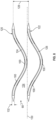
FIG. 4 , anindividual guide vane 62 is illustrated. Theguide vane 62 extends along itslength 72 from anupstream end 74 to adownstream end 76. In the current embodiment, theguide vane 62 is formed in an undulating, sinusoidal-like shape. It will be appreciated that the shape and the number of undulations may vary, andFIG. 4 is but one example of the possible configurations. In other embodiments, theguide vane 62 may have a different number of undulations or may take other shapes, the intent being to sufficiently redirect the air flow through theflow channels 64 to increase interaction of theguide vane 62 with the incoming dust laden air, and therefore to increase the occurrence of impingements and near impingements between thesurfaces air flow stream 68 follows thesurfaces guide vane 62 as the air stream turns. It should be noted that theguide vane 62 has a smoothly transitioning shape between undulations to minimize pressure drop which might otherwise be increased by sharp transitions such as those that would result from corners or conspicuous angles. The curved surfaces of the undulations create localized acceleration zones as theair flow stream 68 follows thesurfaces peaks 86. As the air flows across thevalley 87, its velocity slows, increasing the movement of particles toward theguide vane 62. In this embodiment, the distance of the offset 84 between theupstream end 74 and the peak 86 on an undulation is greater than the spacing (vane pitch 128 as shown inFIG. 8 ), betweenadjacent guide vanes 62 so that air cannot pass straight through theparticle separator unit 56 without being turned by the guide vanes 62. - The
guide vane 62 includes awall structure 90 defining avane plenum 92, which is an internal open space within theguide vane 62. Thewall structure 90 includesside walls walls vane plenum 92. Theguide vane 62 includes a number of openings distributed across thesurfaces holes 100 that extend through thewalls adjacent flow channels 64 and to thevane plenum 92. In this example, the through-holes 100 are inclined toward the incomingair flow stream 68 so that their inlet ends 102 are located upstream from their outlet ends 104. In this embodiment, air is exhausted from thevane plenum 92 through an exhaust path (such as described below), and therefore each inlet end 102 registers with theflow stream 68 and each outlet end registers with thevane plenum 92. In other embodiments, at least some of the through-holes 100 may be disposed and oriented so that air flows through them out of thevane plenum 92 and back to theair flow stream 68. - As shown in
FIG. 5 , the through-holes 100 are distributed across thesurfaces surfaces holes 100 are generally cylindrical in shape with circular openings, however, other shapes are contemplated by the current disclosure including and a polygon or complex shape. In addition, other through-hole layout patterns are contemplated, the intent being to distribute the through-holes 100 on thesurfaces air flow stream 68 and to maximize capture of particles.FIG. 6 shows theplate 93 as viewed from its side. The through-holes 100 are arranged in rows longitudinally along theguide vane 62. The through-holes in adjacent rows are staggered relative to one another so as to not be aligned laterally. Non-alignment increase the efficiency of particle capture. - As illustrated in
FIGS. 4 and 5 , theguide vanes 62 of the current embodiment are constructed of two discrete plates mating together for simplicity of through-hole 100 formation. Theguide vane 62 includes aplate 110 that forms thewall 93, with the perforations forming the through-holes 100. Theplate 110 is disposed spaced from anotherplate 112 which forms thewall 94 and which is also perforated. Theend walls plates vane plenum 92. Theplates end walls plates holes 100 in theplates holes 100 may be made based on the shape of the forming tool. In other embodiments, theguide vane 62 may be made from a single contiguous piece of material with the through-holes 100 formed by casting, molding, boring or other manufacturing processes. Because theparticle separator unit 56 of the current embodiment operates under exposure to ambient air, it may be constructed from a wide variety of materials including metals, polymers, composites, and others. In embodiments where the incoming gas stream is something other than air or is at an elevated temperature, a more durable material may be used. - As illustrated in
FIG. 7 , aguide vane 111 is illustrated with twovane plenums guide vane 111 is constructed of three discrete plates mating together for simplicity of through-hole 100 formation. Theguide vane 111 includes aplate 115 that forms an outside wall, with perforations forming the through-holes 100. Theplate 115 is disposed spaced from anotherplate 116 which forms acenter wall 117 between thevane plenums plate 116 is free of perforations. Theplate 116 is disposed spaced from anotherplate 117, which is also perforated with throughholes 100. Theend walls plates vane plenums plates end walls guide vane 111 may be formed either before or after theplates vane plenums holes 100 for capture and retention of particles. - Referring to
FIG. 8 , a pair ofguide vanes air flow stream 68. Each through-hole 100 is formed through its respective wall thereby opening theair flow stream 68 to thevane plenums vane pitch 128 between theguide vanes sight 130 in theflow channels 134 between theguide vanes sight 130 means that there is no direct straight path for theair flow stream 68 when passing through a flow channel in the area of theguide vanes air flow stream 68 to turn. Zero line ofsight 130 maximizes interaction between theair flow stream 68 and the through-holes 100 to increase capture efficiency of particles. In some embodiments, theguide vanes - As illustrated in
FIG. 8 ,vane thickness 132 is the thickness of theguide vane 120 at points away from the narrowed ends, andvane pitch 128 is the distance between the centers of adjacent guide vanes 62. Thevane thickness 132 is selected to minimize pressure drop through theparticle separator unit 56 and in this embodiment, is consistent along the length of theguide vane 120, except at the ends, which are narrowed for smooth air flow. Thethickness 132 of theguide vanes holes 100 may be tailored to maintain a negligible pressure drop through theparticle separator unit 56 of less than one percent. In certain embodiments, the through-holes 100 have a diameter of 1-2 millimeters and thevane pitch 128 is 60 millimeters. The total number ofguide vanes 62 and the total number of through-holes 100 may be balanced with resulting the pressure drop to achieve a desired particle capture rate with an acceptable pressure drop. - Placement of the through-
holes 100 may be strategically determined based on the direction of theair flow stream 68 and the shape of theguide vane 140. In the example ofFIG. 9 , theguide vane 140 has a sinusoidal-like shape withbends walls vane plenum 153. Thebends segment 154 of thewall 150 facing the oncomingair flow stream 68. The throughholes 100 in thesegment 154 are oriented so that theirends 156 are disposed in anupstream direction 158 relative to theirends 160. In this example, theends 156 are disposed on theair flow stream 68 side of thewall 150 and theends 160 are disposed on thevane plenum 153 side of thewall 150. This results in the through-holes 100 being inclined toward the oncomingair flow stream 68 to maximize particle capture and entry into thevane plenum 153. The through-holes 100 in thesegment 162 in the area of thebend 146 of thewall 152 are similarly oriented for capture maximization and for air, with entrained particles, flow into thevane plenum 153. - The
bend 142 results in asegment 164 of thewall 152 facing away from the oncomingair flow stream 68 creating alow pressure area 166 outside thewall 152. The throughholes 100 in thesegment 164 are oriented so that theirends 168 are disposed in anupstream direction 158 relative to theirends 170. In this example, theends 168 are disposed on thevane plenum 153 side of thewall 152 and theends 170 are disposed on theair flow stream 68 side of thewall 152. This results in the through-holes 100 being inclined away from the oncomingair flow stream 68 to facilitate air flow out of thevane plenum 153 to thelow pressure area 166. The location of the through-holes 100 in thesegment 164 is generally in theupstream direction 158 from the through-holes 100 in thesegment 154. As a result, the particles entering through thesegment 154 are unlikely to exit thevane plenum 153 with air exiting through thesegment 164. Asegment 174 of thewall 150 has through-holes 100 oriented similarly, for air flow out of thevane plenum 153 to alow pressure area 176. In general, the number of capture through-holes in thesegments holes 100 in thesegments - In the area of the
bend 150, and specifically in thesegment 178 of thewall 154, a number of throughholes 100 are oriented with a small upward inclination (from stream side to the vane plenum side) to the horizontal in addition to the inclination with the oncoming air stream as the through-holes 100 in thesegment 154 are inclined. The incline is schematically shown inFIG. 10 . This enables the through-holes 100 to act as incoming jets to direct particles within thevane plenum 153 away from thewall 150 to inhibit particles from escaping thevane plenum 153 out the through-holes 100 in thesegment 174 just downstream of thebend 144. In addition, the through-holes 100 in thesegment 178 help move particles towards a discharge mechanism as described below. - Referring to
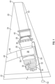
FIG. 10 , one such discharge mechanism is illustrated in the form of ascavenging system 180. In thescavenging system 180, theparticle separator unit 56 is disposed in theinlet duct 46 such as of theAPU 26. The vane plenums 92 of theguide vanes 62 are open and connected with acommon plenum 182 so that particles within thevane plenums 92 may move into thecommon plenum 182. As noted above, some of the through-holes 100 may be oriented to assist in particle movement to thecommon plenum 182. In this embodiment, thecommon plenum 182 is defined within theend plate 67. Air and particles may be drawn from thecommon plenum 182, and thevane plenums 92 by suction, which may be created by a number of mechanisms. In this example, surge air purge from thecompressor 38 is used to draw air and particles. Surge is an unwanted phenomenon of operation of thecompressor 38 and may be avoided or reduced by venting a portion of the compressor's discharge flow to maintain thecompressor 38 at operating conditions away from its surge limit. In this example, the ventedair 184 is controlled by asurge control valve 186 that controls flow out of thecompressor 38 for entrainment withexhaust flow 188 from theturbine 28. Accordingly, flow in thesurge duct 190 is intermittent and occurs when air is vented through thesurge control valve 186 to avoid surge. When thesurge control valve 186 is open, air moves from thecompressor 38, through thesurge duct 190 and is entrained in theexhaust flow 188 within theexhaust duct 42 fordischarge 192. Thesurge flow 194 draws particleladen air flow 196 through ascavenge duct 198 connected between thecommon plenum 182 and thesurge duct 190. As a result, particles move from theparticle separator unit 56 and are discharged with theexhaust discharge 192. Accordingly, theparticle separator unit 56 is self-replenished without a need for cleaning downtime.FIG. 10 also schematically shows the orientation of the throughholes 100 in thevarious segments holes 100 in thesegment 178 as compared to the horizontal throughholes 100 in thesegments air flow stream 68, of the guide vanes 62. - Through the examples described herein, an efficient manner of removing particles from a gas flow stream is provided without passing inlet air through a barrier filter, and without a need to divert air flow from its intended purpose. The air flow stream passes through a particle separator and passes by a series of dividers with through-holes and plenums so that particles are removed from the inlet air. The collection activity of the particle collector is entirely passive and may be readily self-refreshed by a scavenging system that draws particles out and exhausts them. The particle separator has applicability wherever particle separation from a fluid stream is desired. While at least one exemplary embodiment has been presented in the foregoing detailed description, it should be appreciated that a vast number of variations exist. It should also be appreciated that the exemplary embodiment or exemplary embodiments are only examples, and are not intended to limit the scope, applicability, or configuration of the invention in any way. Rather, the foregoing detailed description will provide those skilled in the art with a convenient road map for implementing an exemplary embodiment of the invention. It being understood that various changes may be made in the function and arrangement of elements described in an exemplary embodiment without departing from the scope of the invention as set forth in the appended claims.
Claims (15)
- A particle separator (56) comprising:a housing (58) through which a flow stream is directed;a number of guide vanes (62) disposed in the housing, at least one of the guide vanes having a profile wherein the flow stream is guided to follow the profile, at least one of the guide vanes having a wall (93, 94, 95, 96) surrounding an open interior defining a vane plenum (92), with a plurality of through-holes (100) extending through the wall of the guide vane;wherein first ends of through-holes are open to the flow stream and second ends of the through-holes are open to the vane plenum; anda duct (198) connected with the vane plenum and configured to discharge particles collected in the vane plenum, wherein:a first subset of the through-holes is configured to direct flow from the flow stream into the vane plenum, which is configured to collect particles from the flow stream that pass through the first subset of the through-holes; characterized bya second subset of the through-holes is configured to direct flow out of the vane plenum back to the flow stream.
- The particular separator of claim 1, wherein the wall includes side walls (93, 94) and end walls (95, 96) enclosing the vane plenum and the plurality of through-holes include through-holes (100) extending through each of the side walls (93, 94).
- The particle separator of claim 1, wherein the flow stream travels in an upstream to downstream direction, and wherein at least some of the through-holes are inclined at an angle so that each of their respective first end is located at an upstream position relative to their respective second end.
- The particle separator of claim 3, wherein additional of the through-holes are inclined so that their respective first end is located at a downstream position relative to their respective second end.
- The particle separator of claim 1, wherein the guide vanes are spaced from one another at a vane pitch with zero line of sight along the flow stream.
- The particle separator of claim 1, wherein the guide vanes each have two vane plenums separated from one another by a center wall (117).
- The particle separator of claim 1, wherein the vane plenums are each open to a common plenum (182).
- The particle separator of claim 7, wherein the common plenum is connected by the duct with a scavenging system (180) through which particles are exhausted, optionally wherein the scavenging system is connected with a compressor surge duct (190).
- An APU system comprising the particle separator system of Claim 1 in combination with a gas turbine auxiliary power unit, APU, for housing in a tail cone (20) area of an aircraft (22), the tail cone area (20) defining a compartment (24) that houses the APU (26), the APU (26) including a turbine (28) which powers the APU (26), a starter (30) for starting the APU (26), a gearbox (32) for driving various loads including a generator (34) for supplying electrical power, a power compressor (38) for supplying air to the turbine (28), a combustor (36), an eductor system (40) for pumping air, and an exhaust duct (42) for delivering exhaust out of a tail (44) of the aircraft (22), wherein the compressor (38) is arranged to receive outside air from an inlet duct (46) that extends between the APU (26) and an inlet opening (48), wherein the inlet duct (46) includes the particle separator unit (56), disposed to collect particles from the incoming air stream prior to reaching the compressor (38).
- The particle separator of claim 1, wherein each guide vane includes a bend and wherein some of the through-holes at the bend are oriented to direct particles in the vane plenum away from the wall.
- The particle separator of claim 1, comprising first and second end plates (66, 67) to which the guide vanes are connected, wherein at least one of the end plates defines a common plenum (182) to which the vane plenum of each of the guide vanes is connected.
- The particle separator of Claim 1, which is for an inlet duct (46), wherein:each of the guide vanes has a profile wherein the flow stream is guided to follow the profile, each of the guide vanes has a wall surrounding an open interior defining a vane plenum, with a plurality of through-holes extending through the wall of the guide vane connecting the flow stream with the vane plenum, wherein first ends of through-holes are open to the flow stream and second ends of the through-holes are open to the vane plenum;a common plenum (182) is defined by the housing, wherein each of the vane plenums is open to the common plenum; andthe duct is a scavenge duct (198) connected with the common plenum and configured to discharge particles collected in the vane plenums and to self-refresh the particle separator.
- The particle separator of claim 12, wherein:
the second subset of the through-holes is configured to direct flow out of the vane plenum back to the flow stream, improving flow into the vane plenum and assisting particle capture, wherein some of the first subset of through-holes are inclined different than others of the first subset of through-holes and are configured to direct particles away from the wall, into the vane plenum and toward the common plenum. - The particle separator of claim 12, wherein the guide vanes are spaced from one another at a vane pitch with zero line of sight along the flow stream so that the flow stream must turn when passing between adjacent of the guide vanes.
- The particle separator of claim 12, wherein the guide vanes each have two vane plenums separated from one another by a center wall, wherein the center wall is solid without through - holes.
Applications Claiming Priority (1)
| Application Number | Priority Date | Filing Date | Title |
|---|---|---|---|
| US16/653,682 US11446596B2 (en) | 2019-10-15 | 2019-10-15 | Self refreshing particle separator |
Publications (2)
| Publication Number | Publication Date |
|---|---|
| EP3808430A1 EP3808430A1 (en) | 2021-04-21 |
| EP3808430B1 true EP3808430B1 (en) | 2023-08-30 |
Family
ID=72709000
Family Applications (1)
| Application Number | Title | Priority Date | Filing Date |
|---|---|---|---|
| EP20199117.1A Active EP3808430B1 (en) | 2019-10-15 | 2020-09-29 | Self refreshing particle separator |
Country Status (2)
| Country | Link |
|---|---|
| US (1) | US11446596B2 (en) |
| EP (1) | EP3808430B1 (en) |
Cited By (8)
| Publication number | Priority date | Publication date | Assignee | Title |
|---|---|---|---|---|
| US20240280053A1 (en) * | 2023-02-17 | 2024-08-22 | General Electric Company | Reverse flow gas turbine engine having electric machine |
| US20250052193A1 (en) * | 2023-02-17 | 2025-02-13 | General Electric Company | Reverse flow gas turbine engine having electric machine |
| US20250101918A1 (en) * | 2023-02-17 | 2025-03-27 | General Electric Company | Reverse flow gas turbine engine having electric machine |
| US20250122831A1 (en) * | 2023-02-17 | 2025-04-17 | General Electric Company | Reverse flow gas turbine engine having electric machine |
| US12319417B2 (en) | 2023-02-17 | 2025-06-03 | General Electric Company | Reverse flow gas turbine engine having electric machine |
| US12366201B2 (en) | 2023-02-17 | 2025-07-22 | General Electric Company | Reverse flow gas turbine engine having electric machine |
| US12416262B2 (en) | 2023-02-17 | 2025-09-16 | General Electric Company | Reverse flow gas turbine engine having electric machine |
| US12510025B2 (en) | 2023-02-17 | 2025-12-30 | General Electric Company | Reverse flow gas turbine engine having electric machine |
Family Cites Families (16)
| Publication number | Priority date | Publication date | Assignee | Title |
|---|---|---|---|---|
| GB288992A (en) | 1927-04-18 | 1928-11-08 | General Air Filters Corporation | |
| GB421888A (en) | 1933-05-29 | 1934-12-31 | William Henry Owen | Improvements in method of cleaning or removing moisture from gases and vapours |
| US3405511A (en) | 1966-05-16 | 1968-10-15 | Burgess Manning Co | Vane type separator |
| CA1015290A (en) | 1972-12-18 | 1977-08-09 | Pall Corporation | Vortex air cleaner assembly with acoustic attenuator |
| BE867741A (en) | 1978-06-02 | 1978-10-02 | Alsthom Atlantique | DEVICE FOR THE SEPARATION OF PHASES OF A FLUID WHICH IS IN A GASEOUS PHASE AND A LIQUID PHASE |
| US4198219A (en) | 1978-11-22 | 1980-04-15 | The United States Of America As Represented By The Secretary Of The Army | Air inlet grille for engine compartment |
| JPS61250324A (en) | 1985-04-27 | 1986-11-07 | Toushiyou Eng Kk | Noise frequency corresponding type silencer |
| US4704145A (en) | 1986-06-27 | 1987-11-03 | Avco Corporation | Modular multi-channel particle separator |
| US5104431A (en) * | 1990-06-20 | 1992-04-14 | Peerless Manufacturing Company | High capacity vane |
| JP2005252100A (en) | 2004-03-05 | 2005-09-15 | Shinwa Controls Co Ltd | Mist separator and substrate processing apparatus provided with mist separator |
| CN1788143B (en) * | 2004-06-14 | 2011-07-06 | 燃气涡轮效率股份有限公司 | System and apparatus for collecting and treating wastewater from engine cleaning |
| US9546603B2 (en) | 2014-04-03 | 2017-01-17 | Honeywell International Inc. | Engine systems and methods for removing particles from turbine air |
| DE202014006595U1 (en) | 2014-08-18 | 2015-11-19 | Big Dutchman International Gmbh | Filter element for the separation of particles from a particle-loaded crude gas stream |
| US20170089208A1 (en) | 2015-09-30 | 2017-03-30 | General Electric Company | Vane separators with acoustic insulation |
| CN106268050A (en) | 2016-08-10 | 2017-01-04 | 中国石油天然气集团公司 | A kind of blade gas liquid separating apparatus |
| US11035257B2 (en) | 2018-01-23 | 2021-06-15 | Honeywell International Inc. | Driven cavity particle separator |
-
2019
- 2019-10-15 US US16/653,682 patent/US11446596B2/en active Active
-
2020
- 2020-09-29 EP EP20199117.1A patent/EP3808430B1/en active Active
Cited By (13)
| Publication number | Priority date | Publication date | Assignee | Title |
|---|---|---|---|---|
| US20240280053A1 (en) * | 2023-02-17 | 2024-08-22 | General Electric Company | Reverse flow gas turbine engine having electric machine |
| US12188414B2 (en) * | 2023-02-17 | 2025-01-07 | General Electric Company | Reverse flow gas turbine engine having electric machine |
| US20250052193A1 (en) * | 2023-02-17 | 2025-02-13 | General Electric Company | Reverse flow gas turbine engine having electric machine |
| US20250101918A1 (en) * | 2023-02-17 | 2025-03-27 | General Electric Company | Reverse flow gas turbine engine having electric machine |
| US20250122831A1 (en) * | 2023-02-17 | 2025-04-17 | General Electric Company | Reverse flow gas turbine engine having electric machine |
| US12319417B2 (en) | 2023-02-17 | 2025-06-03 | General Electric Company | Reverse flow gas turbine engine having electric machine |
| US12366201B2 (en) | 2023-02-17 | 2025-07-22 | General Electric Company | Reverse flow gas turbine engine having electric machine |
| US12416262B2 (en) | 2023-02-17 | 2025-09-16 | General Electric Company | Reverse flow gas turbine engine having electric machine |
| US12460576B2 (en) * | 2023-02-17 | 2025-11-04 | General Electric Company | Reverse flow gas turbine engine having electric machine |
| US12486797B2 (en) * | 2023-02-17 | 2025-12-02 | General Electric Company | Reverse flow gas turbine engine having electric machine |
| US12510025B2 (en) | 2023-02-17 | 2025-12-30 | General Electric Company | Reverse flow gas turbine engine having electric machine |
| US12545414B2 (en) | 2023-02-17 | 2026-02-10 | General Electric Company | Reverse flow gas turbine engine having electric machine |
| US12560121B2 (en) * | 2023-02-17 | 2026-02-24 | General Electric Company | Reverse flow gas turbine engine having electric machine |
Also Published As
| Publication number | Publication date |
|---|---|
| EP3808430A1 (en) | 2021-04-21 |
| US11446596B2 (en) | 2022-09-20 |
| US20210108567A1 (en) | 2021-04-15 |
Similar Documents
| Publication | Publication Date | Title |
|---|---|---|
| EP3808430B1 (en) | Self refreshing particle separator | |
| US11421595B2 (en) | Scavenge methodologies for turbine engine particle separation concepts | |
| EP1510659B1 (en) | Gas turbine engine comprising a vane assembly in a cooling air flowpath and method for removing particles from a cooling airflow | |
| US4704145A (en) | Modular multi-channel particle separator | |
| EP0965728B1 (en) | Particle trap in a cooling system for gas turbine engines | |
| EP1670564B1 (en) | Separator systems | |
| EP3225818B1 (en) | Turbine engine designs for improved fine particle separation efficiency | |
| CN110753783A (en) | Oil cooling system for gas turbine engine | |
| CN101608564B (en) | Particle separator and method for separating particles from an exhaust gas flow of a combustion engine | |
| JPH0223202A (en) | Cooling device for turbine blade | |
| US12345200B2 (en) | Particle separators for turbomachines and method of operating the same | |
| US20160115916A1 (en) | Inertial Separation Pre-Cleaner | |
| CN114914623A (en) | Exhaust device, battery and motor vehicle | |
| US20140202121A1 (en) | Conical light fod momentum particle separator protector | |
| JP2020514617A (en) | Particle separator assembly for a turbine engine | |
| US7070637B1 (en) | Apparatus for separating particles from a fluid | |
| EP3513859B1 (en) | Driven cavity particle separator | |
| EP1967449A2 (en) | Systems and methods for reducing pressure loss of air flowing froma first area to a second area | |
| US11015469B2 (en) | Coolant airflow assembly particulate filter with panels in series | |
| EP3604140B1 (en) | Air inlet system for auxiliary power units | |
| US8083183B2 (en) | Air discharge device for an aircraft | |
| EP3192740B1 (en) | Drain hole orifice device | |
| JP7312935B2 (en) | Oil smoke collector | |
| CN118757370B (en) | Oil-gas separation structure and compressor using same | |
| JPS591092Y2 (en) | Particulate separation equipment |
Legal Events
| Date | Code | Title | Description |
|---|---|---|---|
| PUAI | Public reference made under article 153(3) epc to a published international application that has entered the european phase |
Free format text: ORIGINAL CODE: 0009012 |
|
| STAA | Information on the status of an ep patent application or granted ep patent |
Free format text: STATUS: THE APPLICATION HAS BEEN PUBLISHED |
|
| AK | Designated contracting states |
Kind code of ref document: A1 Designated state(s): AL AT BE BG CH CY CZ DE DK EE ES FI FR GB GR HR HU IE IS IT LI LT LU LV MC MK MT NL NO PL PT RO RS SE SI SK SM TR |
|
| AX | Request for extension of the european patent |
Extension state: BA ME |
|
| STAA | Information on the status of an ep patent application or granted ep patent |
Free format text: STATUS: REQUEST FOR EXAMINATION WAS MADE |
|
| 17P | Request for examination filed |
Effective date: 20211021 |
|
| RBV | Designated contracting states (corrected) |
Designated state(s): AL AT BE BG CH CY CZ DE DK EE ES FI FR GB GR HR HU IE IS IT LI LT LU LV MC MK MT NL NO PL PT RO RS SE SI SK SM TR |
|
| RAP3 | Party data changed (applicant data changed or rights of an application transferred) |
Owner name: HONEYWELL INTERNATIONAL INC. |
|
| GRAP | Despatch of communication of intention to grant a patent |
Free format text: ORIGINAL CODE: EPIDOSNIGR1 |
|
| STAA | Information on the status of an ep patent application or granted ep patent |
Free format text: STATUS: GRANT OF PATENT IS INTENDED |
|
| INTG | Intention to grant announced |
Effective date: 20230328 |
|
| RIN1 | Information on inventor provided before grant (corrected) |
Inventor name: SHEORAN, YOGENDRA Inventor name: KOLLATI, VIGHNESWARA RAO |
|
| P01 | Opt-out of the competence of the unified patent court (upc) registered |
Effective date: 20230421 |
|
| GRAS | Grant fee paid |
Free format text: ORIGINAL CODE: EPIDOSNIGR3 |
|
| GRAA | (expected) grant |
Free format text: ORIGINAL CODE: 0009210 |
|
| STAA | Information on the status of an ep patent application or granted ep patent |
Free format text: STATUS: THE PATENT HAS BEEN GRANTED |
|
| AK | Designated contracting states |
Kind code of ref document: B1 Designated state(s): AL AT BE BG CH CY CZ DE DK EE ES FI FR GB GR HR HU IE IS IT LI LT LU LV MC MK MT NL NO PL PT RO RS SE SI SK SM TR |
|
| REG | Reference to a national code |
Ref country code: GB Ref legal event code: FG4D |
|
| REG | Reference to a national code |
Ref country code: CH Ref legal event code: EP |
|
| REG | Reference to a national code |
Ref country code: DE Ref legal event code: R096 Ref document number: 602020016588 Country of ref document: DE |
|
| REG | Reference to a national code |
Ref country code: IE Ref legal event code: FG4D |
|
| REG | Reference to a national code |
Ref country code: LT Ref legal event code: MG9D |
|
| REG | Reference to a national code |
Ref country code: NL Ref legal event code: MP Effective date: 20230830 |
|
| REG | Reference to a national code |
Ref country code: AT Ref legal event code: MK05 Ref document number: 1604692 Country of ref document: AT Kind code of ref document: T Effective date: 20230830 |
|
| PG25 | Lapsed in a contracting state [announced via postgrant information from national office to epo] |
Ref country code: GR Free format text: LAPSE BECAUSE OF FAILURE TO SUBMIT A TRANSLATION OF THE DESCRIPTION OR TO PAY THE FEE WITHIN THE PRESCRIBED TIME-LIMIT Effective date: 20231201 |
|
| PG25 | Lapsed in a contracting state [announced via postgrant information from national office to epo] |
Ref country code: IS Free format text: LAPSE BECAUSE OF FAILURE TO SUBMIT A TRANSLATION OF THE DESCRIPTION OR TO PAY THE FEE WITHIN THE PRESCRIBED TIME-LIMIT Effective date: 20231230 |
|
| PG25 | Lapsed in a contracting state [announced via postgrant information from national office to epo] |
Ref country code: SE Free format text: LAPSE BECAUSE OF FAILURE TO SUBMIT A TRANSLATION OF THE DESCRIPTION OR TO PAY THE FEE WITHIN THE PRESCRIBED TIME-LIMIT Effective date: 20230830 Ref country code: RS Free format text: LAPSE BECAUSE OF FAILURE TO SUBMIT A TRANSLATION OF THE DESCRIPTION OR TO PAY THE FEE WITHIN THE PRESCRIBED TIME-LIMIT Effective date: 20230830 Ref country code: NO Free format text: LAPSE BECAUSE OF FAILURE TO SUBMIT A TRANSLATION OF THE DESCRIPTION OR TO PAY THE FEE WITHIN THE PRESCRIBED TIME-LIMIT Effective date: 20231130 Ref country code: LV Free format text: LAPSE BECAUSE OF FAILURE TO SUBMIT A TRANSLATION OF THE DESCRIPTION OR TO PAY THE FEE WITHIN THE PRESCRIBED TIME-LIMIT Effective date: 20230830 Ref country code: LT Free format text: LAPSE BECAUSE OF FAILURE TO SUBMIT A TRANSLATION OF THE DESCRIPTION OR TO PAY THE FEE WITHIN THE PRESCRIBED TIME-LIMIT Effective date: 20230830 Ref country code: IS Free format text: LAPSE BECAUSE OF FAILURE TO SUBMIT A TRANSLATION OF THE DESCRIPTION OR TO PAY THE FEE WITHIN THE PRESCRIBED TIME-LIMIT Effective date: 20231230 Ref country code: HR Free format text: LAPSE BECAUSE OF FAILURE TO SUBMIT A TRANSLATION OF THE DESCRIPTION OR TO PAY THE FEE WITHIN THE PRESCRIBED TIME-LIMIT Effective date: 20230830 Ref country code: GR Free format text: LAPSE BECAUSE OF FAILURE TO SUBMIT A TRANSLATION OF THE DESCRIPTION OR TO PAY THE FEE WITHIN THE PRESCRIBED TIME-LIMIT Effective date: 20231201 Ref country code: FI Free format text: LAPSE BECAUSE OF FAILURE TO SUBMIT A TRANSLATION OF THE DESCRIPTION OR TO PAY THE FEE WITHIN THE PRESCRIBED TIME-LIMIT Effective date: 20230830 Ref country code: AT Free format text: LAPSE BECAUSE OF FAILURE TO SUBMIT A TRANSLATION OF THE DESCRIPTION OR TO PAY THE FEE WITHIN THE PRESCRIBED TIME-LIMIT Effective date: 20230830 |
|
| PG25 | Lapsed in a contracting state [announced via postgrant information from national office to epo] |
Ref country code: PL Free format text: LAPSE BECAUSE OF FAILURE TO SUBMIT A TRANSLATION OF THE DESCRIPTION OR TO PAY THE FEE WITHIN THE PRESCRIBED TIME-LIMIT Effective date: 20230830 Ref country code: NL Free format text: LAPSE BECAUSE OF FAILURE TO SUBMIT A TRANSLATION OF THE DESCRIPTION OR TO PAY THE FEE WITHIN THE PRESCRIBED TIME-LIMIT Effective date: 20230830 |
|
| REG | Reference to a national code |
Ref country code: DE Ref legal event code: R119 Ref document number: 602020016588 Country of ref document: DE |
|
| PG25 | Lapsed in a contracting state [announced via postgrant information from national office to epo] |
Ref country code: ES Free format text: LAPSE BECAUSE OF FAILURE TO SUBMIT A TRANSLATION OF THE DESCRIPTION OR TO PAY THE FEE WITHIN THE PRESCRIBED TIME-LIMIT Effective date: 20230830 |
|
| PG25 | Lapsed in a contracting state [announced via postgrant information from national office to epo] |
Ref country code: SM Free format text: LAPSE BECAUSE OF FAILURE TO SUBMIT A TRANSLATION OF THE DESCRIPTION OR TO PAY THE FEE WITHIN THE PRESCRIBED TIME-LIMIT Effective date: 20230830 Ref country code: RO Free format text: LAPSE BECAUSE OF FAILURE TO SUBMIT A TRANSLATION OF THE DESCRIPTION OR TO PAY THE FEE WITHIN THE PRESCRIBED TIME-LIMIT Effective date: 20230830 Ref country code: ES Free format text: LAPSE BECAUSE OF FAILURE TO SUBMIT A TRANSLATION OF THE DESCRIPTION OR TO PAY THE FEE WITHIN THE PRESCRIBED TIME-LIMIT Effective date: 20230830 Ref country code: EE Free format text: LAPSE BECAUSE OF FAILURE TO SUBMIT A TRANSLATION OF THE DESCRIPTION OR TO PAY THE FEE WITHIN THE PRESCRIBED TIME-LIMIT Effective date: 20230830 Ref country code: DK Free format text: LAPSE BECAUSE OF FAILURE TO SUBMIT A TRANSLATION OF THE DESCRIPTION OR TO PAY THE FEE WITHIN THE PRESCRIBED TIME-LIMIT Effective date: 20230830 Ref country code: CZ Free format text: LAPSE BECAUSE OF FAILURE TO SUBMIT A TRANSLATION OF THE DESCRIPTION OR TO PAY THE FEE WITHIN THE PRESCRIBED TIME-LIMIT Effective date: 20230830 Ref country code: SK Free format text: LAPSE BECAUSE OF FAILURE TO SUBMIT A TRANSLATION OF THE DESCRIPTION OR TO PAY THE FEE WITHIN THE PRESCRIBED TIME-LIMIT Effective date: 20230830 Ref country code: PT Free format text: LAPSE BECAUSE OF FAILURE TO SUBMIT A TRANSLATION OF THE DESCRIPTION OR TO PAY THE FEE WITHIN THE PRESCRIBED TIME-LIMIT Effective date: 20240102 |
|
| REG | Reference to a national code |
Ref country code: CH Ref legal event code: PL |
|
| PG25 | Lapsed in a contracting state [announced via postgrant information from national office to epo] |
Ref country code: LU Free format text: LAPSE BECAUSE OF NON-PAYMENT OF DUE FEES Effective date: 20230929 |
|
| REG | Reference to a national code |
Ref country code: BE Ref legal event code: MM Effective date: 20230930 |
|
| PG25 | Lapsed in a contracting state [announced via postgrant information from national office to epo] |
Ref country code: LU Free format text: LAPSE BECAUSE OF NON-PAYMENT OF DUE FEES Effective date: 20230929 Ref country code: IT Free format text: LAPSE BECAUSE OF FAILURE TO SUBMIT A TRANSLATION OF THE DESCRIPTION OR TO PAY THE FEE WITHIN THE PRESCRIBED TIME-LIMIT Effective date: 20230830 Ref country code: MC Free format text: LAPSE BECAUSE OF FAILURE TO SUBMIT A TRANSLATION OF THE DESCRIPTION OR TO PAY THE FEE WITHIN THE PRESCRIBED TIME-LIMIT Effective date: 20230830 |
|
| REG | Reference to a national code |
Ref country code: IE Ref legal event code: MM4A |
|
| PG25 | Lapsed in a contracting state [announced via postgrant information from national office to epo] |
Ref country code: IE Free format text: LAPSE BECAUSE OF NON-PAYMENT OF DUE FEES Effective date: 20230929 |
|
| PLBE | No opposition filed within time limit |
Free format text: ORIGINAL CODE: 0009261 |
|
| STAA | Information on the status of an ep patent application or granted ep patent |
Free format text: STATUS: NO OPPOSITION FILED WITHIN TIME LIMIT |
|
| PG25 | Lapsed in a contracting state [announced via postgrant information from national office to epo] |
Ref country code: CH Free format text: LAPSE BECAUSE OF NON-PAYMENT OF DUE FEES Effective date: 20230930 |
|
| PG25 | Lapsed in a contracting state [announced via postgrant information from national office to epo] |
Ref country code: IE Free format text: LAPSE BECAUSE OF NON-PAYMENT OF DUE FEES Effective date: 20230929 Ref country code: DE Free format text: LAPSE BECAUSE OF NON-PAYMENT OF DUE FEES Effective date: 20240403 Ref country code: CH Free format text: LAPSE BECAUSE OF NON-PAYMENT OF DUE FEES Effective date: 20230930 Ref country code: SI Free format text: LAPSE BECAUSE OF FAILURE TO SUBMIT A TRANSLATION OF THE DESCRIPTION OR TO PAY THE FEE WITHIN THE PRESCRIBED TIME-LIMIT Effective date: 20230830 |
|
| 26N | No opposition filed |
Effective date: 20240603 |
|
| PG25 | Lapsed in a contracting state [announced via postgrant information from national office to epo] |
Ref country code: BE Free format text: LAPSE BECAUSE OF NON-PAYMENT OF DUE FEES Effective date: 20230930 |
|
| PG25 | Lapsed in a contracting state [announced via postgrant information from national office to epo] |
Ref country code: BG Free format text: LAPSE BECAUSE OF FAILURE TO SUBMIT A TRANSLATION OF THE DESCRIPTION OR TO PAY THE FEE WITHIN THE PRESCRIBED TIME-LIMIT Effective date: 20230830 |
|
| PG25 | Lapsed in a contracting state [announced via postgrant information from national office to epo] |
Ref country code: BG Free format text: LAPSE BECAUSE OF FAILURE TO SUBMIT A TRANSLATION OF THE DESCRIPTION OR TO PAY THE FEE WITHIN THE PRESCRIBED TIME-LIMIT Effective date: 20230830 |
|
| GBPC | Gb: european patent ceased through non-payment of renewal fee |
Effective date: 20240929 |
|
| PG25 | Lapsed in a contracting state [announced via postgrant information from national office to epo] |
Ref country code: GB Free format text: LAPSE BECAUSE OF NON-PAYMENT OF DUE FEES Effective date: 20240929 |
|
| PG25 | Lapsed in a contracting state [announced via postgrant information from national office to epo] |
Ref country code: CY Free format text: LAPSE BECAUSE OF FAILURE TO SUBMIT A TRANSLATION OF THE DESCRIPTION OR TO PAY THE FEE WITHIN THE PRESCRIBED TIME-LIMIT; INVALID AB INITIO Effective date: 20200929 |
|
| PG25 | Lapsed in a contracting state [announced via postgrant information from national office to epo] |
Ref country code: HU Free format text: LAPSE BECAUSE OF FAILURE TO SUBMIT A TRANSLATION OF THE DESCRIPTION OR TO PAY THE FEE WITHIN THE PRESCRIBED TIME-LIMIT; INVALID AB INITIO Effective date: 20200929 |
|
| PGFP | Annual fee paid to national office [announced via postgrant information from national office to epo] |
Ref country code: FR Payment date: 20250925 Year of fee payment: 6 |
|
| PG25 | Lapsed in a contracting state [announced via postgrant information from national office to epo] |
Ref country code: TR Free format text: LAPSE BECAUSE OF FAILURE TO SUBMIT A TRANSLATION OF THE DESCRIPTION OR TO PAY THE FEE WITHIN THE PRESCRIBED TIME-LIMIT Effective date: 20230830 |