EP3808322B1 - Remote control for a medical apparatus, system of the remote control and the medical apparatus, and method for operating the medical apparatus - Google Patents
Remote control for a medical apparatus, system of the remote control and the medical apparatus, and method for operating the medical apparatus Download PDFInfo
- Publication number
- EP3808322B1 EP3808322B1 EP19203771.1A EP19203771A EP3808322B1 EP 3808322 B1 EP3808322 B1 EP 3808322B1 EP 19203771 A EP19203771 A EP 19203771A EP 3808322 B1 EP3808322 B1 EP 3808322B1
- Authority
- EP
- European Patent Office
- Prior art keywords
- remote control
- motion
- control
- axis
- medical apparatus
- Prior art date
- Legal status (The legal status is an assumption and is not a legal conclusion. Google has not performed a legal analysis and makes no representation as to the accuracy of the status listed.)
- Active
Links
Images



Classifications
-
- A—HUMAN NECESSITIES
- A61—MEDICAL OR VETERINARY SCIENCE; HYGIENE
- A61G—TRANSPORT, PERSONAL CONVEYANCES, OR ACCOMMODATION SPECIALLY ADAPTED FOR PATIENTS OR DISABLED PERSONS; OPERATING TABLES OR CHAIRS; CHAIRS FOR DENTISTRY; FUNERAL DEVICES
- A61G13/00—Operating tables; Auxiliary appliances therefor
- A61G13/02—Adjustable operating tables; Controls therefor
- A61G13/08—Adjustable operating tables; Controls therefor the table being divided into different adjustable sections
-
- A—HUMAN NECESSITIES
- A61—MEDICAL OR VETERINARY SCIENCE; HYGIENE
- A61G—TRANSPORT, PERSONAL CONVEYANCES, OR ACCOMMODATION SPECIALLY ADAPTED FOR PATIENTS OR DISABLED PERSONS; OPERATING TABLES OR CHAIRS; CHAIRS FOR DENTISTRY; FUNERAL DEVICES
- A61G2203/00—General characteristics of devices
- A61G2203/10—General characteristics of devices characterised by specific control means, e.g. for adjustment or steering
- A61G2203/12—Remote controls
Definitions
- the invention relates to a remote control for a medical apparatus, a system of the remote control and the medical apparatus, and a method for operating the medical apparatus, in particular, to a remote control for a medical apparatus having several movable segments driven in a controlled manner, a system of the remote control and the medical apparatus, and a method for operating the medical apparatus.
- a remote control for a medical apparatus which controls motions of movable segments of the medical apparatus is known.
- the remote control usually includes at least one release switch and several switches for controlling motions in different directions of the respective movable segments.
- EP 2 455 959 A1 discloses such a remote control.
- the number of movable components i.e., the movable segments or other movable components of the operating table. Therefore, the number of the switches actuated by buttons or soft keys of a touch screen increased and the existing remote controls had the disadvantage that, due to the increased number of buttons or soft keys, an operation of the operating table became uncomfortable.
- an intuitive operation in particular, an adjustment of a speed of the motion of the movable components was not provided.
- US 2009/0126115 A1 provides a remote controller for an adjustable support apparatus for supporting a patient which includes an input device configured to accept control commands for adjusting a support apparatus for supporting a patient, at least one sensor configured to detect a pick-up of the remote controller by a user, and a transmitter device configured to transmit the control commands to the support apparatus for supporting a patient. The detection of the pick-up of the remote controller by the user activates the remote controller.
- US 2012/0118718 A1 provides a switching device for a medical apparatus which includes a first switching member adapted to select an assigned operating function of the medical apparatus; and a second switching member adapted to permit the selecting of the assigned operating function of the first switching member.
- the second switching member is adapted such that it has a detection space in which it detects a presence of an operating object; and the first switching member is arranged in the detection space of the second switching member.
- the switching device includes a touch screen by which basic adjustments can be controlled.
- the invention is based on the object to overcome the above disadvantages and to provide a remote control for a medical apparatus enabling a comfortable operation of the medical apparatus in an intuitive manner.
- a remote control for controlling a medical apparatus having at least one driven movable component comprises a sensor configured to detect a position and a motion of the remote control, and at least one release switch.
- the remote control is configured to emit a control signal capable of controlling a motion of the at least one driven movable component according to a motion of the remote control detected by the sensor when a control of the motion of the at least one driven movable component is released by actuating the at least one release switch.
- the remote control further comprises a display configured to display a preview of a motion of the at least one driven movable component according to the control signal.
- the remote control is configured to emit the control signal according to a direction of the motion of the remote control detected by the sensor with respect to a position of the remote control when the at least one release switch is actuated to start the release of the control of the motion of the at least one driven movable component.
- the remote control is configured to emit the control signal according to an amount of the motion of the remote control.
- the remote control is configured to emit the control signal according to a speed of the motion of the remote control.
- the remote control comprises a touchscreen display.
- Such a touch display or touchscreen enables an easy change of soft keys provided for different medical apparatuses or different configurations of one kind of medical apparatuses. Moreover, different languages or pictograms for denoting the soft keys are possible for an easy operation of the remote control.
- the touchscreen display and the display configured to display a preview of the motion of the at least one driven movable component according to the control signal are the same display.
- the remote control has an elongated shape and a first axis parallel to the elongated shape of the remote control and a second axis perpendicular to the elongated shape of the remote control, and the remote control is configured to emit the control signal according to a direction of the motion of the remote control around at least one of the first axis and the second axis.
- easy and unambiguous motions of the remote control are used for determining the motion of the movable component of the medical apparatus so that the intuitive operation of the medical apparatus is easily possible and the remote control can be operated easier.
- the remote control is configured to emit the control signal according to the direction of the motion of the remote control around at least one of the first axis and the second axis if the motion of the remote control around the at least one of the first axis and the second axis exceeds a predefined threshold.
- the remote control can be operated more easily since a motion of the remote control is not required in a very exact manner and an unintended operation around one of the first and second axis is quite safe prevented.
- a system of the remote control and the medical apparatus is provided.
- the remote control is configured to control the motion of the at least one driven movable component of the medical apparatus by the control signal.
- the medical apparatus can be comfortably operated without a need for searching an appropriate button or soft key for operating a specific motion of the movable component of the medical apparatus.
- the remote control is configured to control a direction of the motion of the at least one driven movable component according to a direction of the motion of the remote control with respect to a position of the remote control when the at least one release switch starts to release the control of the motion.
- the remote control comprises several release switches
- the medical apparatus comprises several driven movable components respectively driven by a driving device
- the several release switches are respectively assigned to a specific motion of one of the driven movable components.
- several movable components of the medical apparatus can be controlled in an easy and intuitive manner.
- one movable components performs several motions, for example, by one release switch, a height adjustment of a tabletop of an operating table can be released and, by another release switch, tilting of the tabletop around its longitudinal axis can be released, therefore, the several release switches release the control of the motions of one movable component.
- the control of this motion is released, so that the several release switches release the motions of several driven movable components.
- the medical apparatus comprises at least one driven movable component which performs several motions respectively driven by a driving device
- the system is configured such that the several motions are controlled by the remote control when the several motions of the at least one driven movable component are released by a release button assigned to the at least one driven movable component, wherein the several motions are controlled according to motions of the remote control around a first axis parallel to an elongated shape of the remote control and a second axis perpendicular to the elongated shape of the remote control.
- easy and unambiguous motions of the remote control are used for determining the motion of the movable component of the medical apparatus so that the intuitive operation of the medical apparatus is easily possible and the remote control can be operated more easily since no further release switches for releasing the several motions of the at least one driven movable component are necessary.
- the medical apparatus is configured as an operating table.
- an operating table can comprise a large quantity of driven movable segments for adjusting the position of a patient in a surgical treatment and of other driven movable components. Moreover, there is a necessity for adjusting the movable segments during surgery. Therefore, the easy and intuitive operation of the operating table is a tremendous advantage.
- one of the at least one driven components is formed by a locking device configured to lock a motion of the operating table by touching a face supporting the operating table.
- a position of the operating table before a surgical intervention can be easily secured and after the surgical intervention, the operating table the secured position can be easily released in an intuitive manner.
- one of the at least one driven components is formed by a wheel of the operating table, wherein the wheel comprises a drive and the wheel is configured to move the operating table by the drive.
- the motion of the operating table together with the patient into an operating theatre and out of an operating theatre is easily possible in an easy and intuitive manner of controlling.
- a method for operating a medical apparatus by means of a remote control comprises the steps: releasing a control of a motion of a specific one of driven movable components of the medical apparatus by actuating a specific release switch of the remote control, controlling a motion of the specific one of the movable components by moving the remote control with respect to a position of the remote control when the specific release switch starts to release the control of the motion of the specific one of the movable components, and displaying, on a display of the remote control, a preview of the motion of the specific one of the movable components according to the control signal.
- the driven movable components of the medical apparatus can be operated without a need for searching an appropriate button or soft key for operating a specific motion of the movable component of the medical apparatus.
- a direction of the motion of the specific one of the driven movable components is defined by a direction of motion of the remote control around at least one of an axis parallel to an elongated shape of the remote control and an axis perpendicular to the elongated shape of the remote control.
- the motion of the specific one of the driven movable components is stopped when the remote control is moved into a horizontal position.
- Fig. 1 shows a system 1 according to the invention including a remote control 2 in a schematic plan view and an operating table as an embodiment of a medical apparatus 3 in a schematic side view.
- the medical apparatus 3 comprises several movable components, in particular several movable segments, namely, an entire tabletop 4, and a head plate 4' and a leg plate 4" of the tabletop 4.
- the medical apparatus 1 further comprises a driven locking device 4′′′ and a driven wheel 4"".
- the movable segments 4, 4', 4" are respectively driven by at least one driving device (not shown).
- the tabletop 4 is moved by a first driving device (not shown) in a vertical direction depicted by arrow H for adjusting a height of the tabletop 4. Further, the tabletop 4 is tilted by a second driving device (not shown) into a Trendelenburg position or an Anti-Trendelenburg position as depicted by arrow T. Furthermore, the tabletop 4 is displaced by a third driving device (not shown) along a longitudinal axis of the tabletop 4 as depicted by arrow L.
- the head plate 4' is tilted by a fourth driving device (not shown) as depicted by arrow T H and the leg plate 4" is tilted by a fifth driving device (not shown) as depicted by arrow T L .
- the medical apparatus 3 is provided with another number of driven movable segments 4, 4', 4", wherein at least one driven segment 4, 4', 4" movable in different directions is provided.
- the driven locking device 4′′′ comprises jack up stamps as support structures for securing a sure footing of the medical apparatus 1, i.e. for locking a motion of the entire operating table by touching a face supporting the operating table, i.e. a floor.
- the jack up stamps are lowered for touching the floor and, as the case may be, for lifting the operating table in order to lock the operating table.
- the jack up stamps are retracted and there is a gap between the jack up stamps and the face supporting the operating table.
- the jack up stamps are driven by a hydraulic drive.
- the jack up stamps are driven by electric drives or, further alternatively, the locking device is not provided, e.g., in case of a stationary operating table.
- the driven wheel 4"" is provided as a fifth wheel in a center of a chassis of the operating table additionally to wheels for moving the medical apparatus 1 in corners of the chassis of the operating table.
- the fifth wheel comprises a drive and the wheel moves the operating table by the drive when the wheel contacts the face supporting the operating table.
- the wheels in the corners of the chassis of the operating table can be formed as the driven wheel 4 ⁇ or, further alternatively, the driven wheel is not provided, e.g., in case of a stationary operating table.
- the remote control 2 comprises a sensor 5.
- the sensor 5 comprises an inclinometer.
- the sensor 5 comprises another type of sensor, e.g., an acceleration sensors or a gyroscope combined with a geomagnetic sensor.
- the sensor 5 detects a position and a motion or an acceleration of the remote control 2.
- the remote control 2 comprises seven release switches 6.
- the release switches 6 are respectively assigned to a specific motion of one of the driven movable segments 4, 4', 4", of the locking device 4′′′, and of the driven wheel 4"".
- a first one of the release switches 6, the control of the vertical motion of the tabletop 4 can be released
- a second one of the release switches 6, the control of the tilting of the tabletop 4 into the Trendelenburg position or Anti-Trendelenburg position and a tilting around a longitudinal axis of the tabletop 4 can be released.
- a third one of the release switches 6 releases the control of the displacement of the tabletop 4 in the longitudinal direction of the tabletop 4, a fourth one of the release switches 6 releases the control of the tilting of the head plate 4', and a fifth one of the release switches 6 releases the control of the tilting of the leg plate 4".
- a sixth one of the release switches 6 releases the control of the locking device 4′′′, i.e., initiates lifting or lowering the jack up stamps, and a seventh one of the release switches releases the control of the driven wheel 4 ⁇ for driving the operating table.
- another number of release switches 6, e.g., according to a number of motions of the movable components 4, 4', 4", 4'", 4"", merely one release switch 6, or more than two release switches 6, are provided.
- the remote control 2 has an elongated shape and it has an axis A parallel to the elongated shape in a X axis direction of the remote control 2 and an axis B perpendicular to the elongated shape in a Y axis direction of the remote control 2.
- the remote control 2 does not have an elongated shape and the axes A and B, if necessary, are determined by definition.
- the remote control 2 further comprises a communication interface 7.
- the communication interface 7 establishes a communication 8 to the medical apparatus 3 in a wireless manner.
- the communication interface 7 has a connection cable and establishes the communication 8 to the medical apparatus 3 in a wired manner.
- the remote control 2 emits a control signal capable of controlling the motion of the movable components 4, 4', 4", 4′′′, 4 ⁇ according to a motion of the remote control 2 detected by the sensor 5 when the control of the motion of the driven movable components 4, 4', 4", 4′′′, 4"" is released by actuating the release switch 6.
- the remote control 2 emits the control signal according to a direction of the motion of the remote control 2 detected by the sensor 5 with respect to a position of the remote control 2 when the release switch 6 starts to release the motion.
- the remote control 2 emits the control signal according to an amount of the motion of the remote control 2.
- the remote control 2 emits the control signal according to a speed of the motion of the remote control 2.
- the amount and/or the speed of the motion of the remote control 2 are not considered, and, further alternatively, the direction of the motion is not considered but any motion is considered for moving the driven movable component 4, 4', 4", 4′′′, 4"", e.g., in a reciprocating manner.
- the remote control 2 is configured to control the direction of the motion of the driven movable components 4, 4', 4", 4′′′, 4"" according to the direction of the motion of the remote control 2 with respect to a position of the remote control 2 when the release button 6 starts to release the motion. Furthermore, the remote control 2 is configured to control a speed of the motion of the driven movable components 4, 4', 4", 4′′′, 4"" according to the amount of the motion of the remote control 2 with respect to the position of the remote control 2 when the release button 6 starts to release the motion, wherein the speed of the driven movable components 4, 4', 4", 4′′′, 4 ⁇ is the higher the larger the amount of the motion of the remote control 2 is.
- the speed can be reduced.
- a sensitivity of the remote control 2 can be adjusted. In case of a high sensitivity, 100% of the speed of the driven movable components 4, 4', 4", 4′′′, 4"" is achieved upon tilting of the remote control 2 of 30 degrees around one of the axes A or B.
- the remote control 2 is configured to control the speed of the motion of the driven movable components 4, 4', 4", 4′′′, 4"" according to the speed of the motion of the remote control 2, wherein the speed of the motion of the driven movable components 4, 4', 4", 4′′′, 4 ⁇ is the higher the higher the speed of the motion of the remote control 2 is.
- the amount and/or the speed of the motion of the remote control 2 is not considered for the control of the speed of the driven movable components 4, 4', 4", 4′′′, 4"".
- the speed of the motion can be adjusted between 1 % and 100 % of a nominal speed.
- an adjusted speed is fix independently from the manner of tilting the remote control 2.
- the motion of the remote control 2 detected by the sensor 5 is a tilting around the axis B of the remote control 2 perpendicular to its elongated shape and a tilting around the longitudinal axis A of the remote control 2 parallel to its elongated shape.
- the vertical motion of the tabletop 4 and the displacement motions along the axis L are controlled.
- tilting the remote control 2 in one direction the tabletop 4 is lifted and, by tilting the remote control in the other direction, the tabletop 4 is lowered.
- any of the motions are controlled either by detecting the motion around the axis A of the remote control 2, by detecting the motion around the axis B of the remote control 2, or by detecting the motion around the axis A and the axis B.
- a combined motion of the remote control 2, i.e., the tilting around the axis B of the remote control 2 and the tilting around the longitudinal axis A of the remote control 2 controls several motions respectively driven by a driving device of one of the movable components 4, 4", 4′′′, 4"".
- a control signal for approaching the Trendelenburg position or the Anti-Trendelenburg position is emitted and the motion is performed by the medical apparatus 1, and, simultaneously, when tilting the remote control 2 around the longitudinal axis A of the remote control 2, a control signal for tilting of the tabletop 4 according to a direction of the tilting of the remote control 2 is emitted and the motion is performed by the medical apparatus 1.
- the leg section 4" is partitioned along the longitudinal axis of the tabletop 4 and it comprises a left leg section and a right leg section. Upward or downward motion of one of the left and right leg sections is actuated upon releasing the control of the leg section 4" by the respective release switch 6 and upon tilting the remote control 2 in a respective leftward or rightward direction and upward or downward for emitting a respective control signal by the remote control 2 and the motion is performed by the medical apparatus 1.
- Fig 2 shows a starting position and an end position of the remote control 2 in a side view when the remote control 2 is tilted around the axis B in the Y axis direction ( Fig. 1 ) of the remote control 2 perpendicular to an elongated shape of the remote control 2 for controlling one of the motions.
- the initial position of the remote control 2 where the release switch 6 is actuated is depicted by dashed lines and the end position of the remote control 2 is depicted by solid lines.
- the speed and the direction of the motion of the driven movable components 4, 4', 4", 4′′′, 4"" are determined by the movement of the remote control 2 around the axis B.
- a Z axis of the remote control 2 is oriented vertically so the remote control 2 is oriented in a horizontal position.
- Fig. 3 shows another starting position and the end position of the remote control 2 of Fig. 2 in the side view when the remote control 2 is tilted around the axis B perpendicular to the elongated shape of the remote control 2 for controlling one of the motions.
- the initial position of the remote control 2 where the release switch 6 is actuated is depicted by dashed lines and the end position of the remote control 2 is depicted by solid lines.
- Fig. 4 shows the starting position and the end position of the remote control 2 in a front view when the remote control 2 is tilted around the axis A in the X axis direction ( Fig. 1 ) of the remote control 2 parallel to an elongated shape of the remote control 2.
- the initial position of the remote control 2 where the release switch 6 is actuated is depicted by dashed lines and the end position of the remote control 2 is depicted by solid lines.
- the speed and the direction of the motion of the driven movable components 4, 4', 4", 4′′′, 4 ⁇ , the control of which is released by actuating the respective release switch 6, are determined by the movement of the remote control 2 around the axis A.
- the Z axis of the remote control 2 is oriented vertically so the remote control 2 is oriented in a horizontal position.
- Fig. 5 shows another starting position and the end position of the remote control 2 of Fig. 4 in the front view when the remote control 2 is tilted around the axis A parallel to the elongated shape of the remote control 2 for controlling one of the motions.
- This figure shows that the motion of the driven components 4, 4', 4", 4′′′, 4 ⁇ of the medical apparatus 3 is not to be controlled compulsorily starting from the horizontal position of the remote control 2 but, also, another position is possible if the release switch 6 is actuated in this position and the remote control 2 is moved in a specific manner in order to control the motion.
- the control signal according to the direction of the motion of the remote control 2 around at least one of the first axis A and the second axis B is only emitted if the motion of the remote control 2 around the at least one of the first axis A and the second axis B exceeds a predefined threshold.
- the threshold is set to 3 degrees. In alternative embodiments, the threshold is set to other appropriate values, preferably between zero degrees and 6 degrees or no threshold is set.
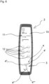
- Fig. 6 shows a plan view of the remote control 2.
- the remote control 2 comprises a display 10 configured to detect a location of a touch of an object, wherein the display 10 is commonly denoted as a touchscreen.
- the object usually is a finger of an operator, i.e., of an operating room nurse.
- the display 10 displays several operating states 11 of the operating table. These operating states are, e.g. a status as, e.g., a height, a longitudinal travel or a Trendelenburg angle, error messages, user information, etc.. Further, the display 10 depicts soft keys 12 having an appearance of usual press buttons. Alternatively, the soft keys 12 have another appearance. When pressing one of the soft keys 12, one of the release switches 6 (not shown in Fig. 6 ) is actuated.
- the display 10 is further configured to display a preview of the motion of the at least one driven movable component 4, 4', 4", ′′′, 4 ⁇ according to the control signal so as to depict a live preview of the motions.
- Fig. 7 shows a flow chart of a method according to the invention.
- a first step S1 the control of a specific one of the motions of the driven movable components 4, 4', 4", 4′′′, 4 ⁇ of the medical apparatus 3 is released by actuating a specific release switch 6 of the remote control 2 assigned to the specific motion.
- a next step S2 the motion of the specific one of the movable components 4, 4', 4", 4′′′, 4 ⁇ , 4 ⁇ is controlled by moving the remote control 2 with respect to a position of the remote control 2 when the specific release switch 6 is actuated.
- the direction of the motion of the specific one of the driven movable components 4, 4', 4", 4′′′, 4 ⁇ is defined by the direction of motion of the remote control 2 around the axis B perpendicular to an elongated shape of the remote control 2 and/or around the axis A parallel to the elongated shape of the remote control 2.
- the remote control 2 emits a stop command for stopping the motion of the driven movable components 4, 4', 4", 4′′′, 4 ⁇ when the remote control 2 is moved into a horizontal position so that the motion of the specific one of the driven movable components 4, 4', 4", 4′′′, 4"" is stopped.
- This function is not compulsorily and, alternatively, the motion is stopped when the release switch 6 is not actuated anymore and the release switch 6 does not release the command anymore.
- the horizontal position is detected by the inclinometer or, alternatively, by the acceleration sensor.
- the acceleration sensor detects components of acceleration forces in the directions of three axes X, Y, Z of the remote control 2. If the component of the acceleration force in the direction of the Z axis of the remote control 2 amounts 1g, the remote control 2 is determined as being oriented in the horizontal position.
Landscapes
- Health & Medical Sciences (AREA)
- Engineering & Computer Science (AREA)
- Biomedical Technology (AREA)
- Life Sciences & Earth Sciences (AREA)
- Animal Behavior & Ethology (AREA)
- General Health & Medical Sciences (AREA)
- Public Health (AREA)
- Veterinary Medicine (AREA)
- Accommodation For Nursing Or Treatment Tables (AREA)
Description
- The invention relates to a remote control for a medical apparatus, a system of the remote control and the medical apparatus, and a method for operating the medical apparatus, in particular, to a remote control for a medical apparatus having several movable segments driven in a controlled manner, a system of the remote control and the medical apparatus, and a method for operating the medical apparatus.
- A remote control for a medical apparatus which controls motions of movable segments of the medical apparatus is known. For security against unintended use, the remote control usually includes at least one release switch and several switches for controlling motions in different directions of the respective movable segments.
EP 2 455 959 A1 -
US 2009/0126115 A1 provides a remote controller for an adjustable support apparatus for supporting a patient which includes an input device configured to accept control commands for adjusting a support apparatus for supporting a patient, at least one sensor configured to detect a pick-up of the remote controller by a user, and a transmitter device configured to transmit the control commands to the support apparatus for supporting a patient. The detection of the pick-up of the remote controller by the user activates the remote controller. -
US 2012/0118718 A1 provides a switching device for a medical apparatus which includes a first switching member adapted to select an assigned operating function of the medical apparatus; and a second switching member adapted to permit the selecting of the assigned operating function of the first switching member. The second switching member is adapted such that it has a detection space in which it detects a presence of an operating object; and the first switching member is arranged in the detection space of the second switching member. The switching device includes a touch screen by which basic adjustments can be controlled. - The invention is based on the object to overcome the above disadvantages and to provide a remote control for a medical apparatus enabling a comfortable operation of the medical apparatus in an intuitive manner.
- The object is achieved by a remote control according to claim 1, a system according to claim 9, and a method according to claim 16. Further developments of the invention are included in the dependent claims.
- According to an aspect of the invention, a remote control for controlling a medical apparatus having at least one driven movable component comprises a sensor configured to detect a position and a motion of the remote control, and at least one release switch. The remote control is configured to emit a control signal capable of controlling a motion of the at least one driven movable component according to a motion of the remote control detected by the sensor when a control of the motion of the at least one driven movable component is released by actuating the at least one release switch. The remote control further comprises a display configured to display a preview of a motion of the at least one driven movable component according to the control signal.
- By such a remote control, merely pressing of one button or one soft key for actuating the release switch is necessary for emitting a specific control signal since, after the release by the release switch, the control signal is then emitted due to the motion of the remote control itself.
- By this display, an operator can easily verify the intended motion of the medical apparatus.
- In an advantageous implementation of the remote control, the remote control is configured to emit the control signal according to a direction of the motion of the remote control detected by the sensor with respect to a position of the remote control when the at least one release switch is actuated to start the release of the control of the motion of the at least one driven movable component.
- When the control signal is emitted according to the direction of the motion of the remote control, an intuitive operation or motion of the movable component is simply possible by moving the remote control according to a desired motion of the movable component.
- In a further advantageous implementation of the remote control, the remote control is configured to emit the control signal according to an amount of the motion of the remote control.
- By emitting the control signal according to the amount of the motion of the remote control, a more precise command including characteristics of the motion of the remote control can be emitted for controlling the medical apparatus easily in an intuitive manner.
- In a further advantageous implementation of the remote control, the remote control is configured to emit the control signal according to a speed of the motion of the remote control.
- By emitting the control signal according to the speed of the motion of the remote control, also, a more precise command including characteristics of the motion can be emitted for comfortably controlling the medical apparatus in an intuitive manner.
- According to a further advantageous implementation of the remote control, the remote control comprises a touchscreen display.
- Such a touch display or touchscreen enables an easy change of soft keys provided for different medical apparatuses or different configurations of one kind of medical apparatuses. Moreover, different languages or pictograms for denoting the soft keys are possible for an easy operation of the remote control.
- In a further advantageous implementation of the remote control, the touchscreen display and the display configured to display a preview of the motion of the at least one driven movable component according to the control signal are the same display.
- According to a further advantageous implementation of the remote control, the remote control has an elongated shape and a first axis parallel to the elongated shape of the remote control and a second axis perpendicular to the elongated shape of the remote control, and the remote control is configured to emit the control signal according to a direction of the motion of the remote control around at least one of the first axis and the second axis.
- In this implementation, easy and unambiguous motions of the remote control are used for determining the motion of the movable component of the medical apparatus so that the intuitive operation of the medical apparatus is easily possible and the remote control can be operated easier.
- In a further advantageous implementation of the remote control, the remote control is configured to emit the control signal according to the direction of the motion of the remote control around at least one of the first axis and the second axis if the motion of the remote control around the at least one of the first axis and the second axis exceeds a predefined threshold.
- By the emission of the control signal not before exceeding a predefined threshold of the motion of the remote control around the at least one of the first axis and the second axis, the remote control can be operated more easily since a motion of the remote control is not required in a very exact manner and an unintended operation around one of the first and second axis is quite safe prevented.
- According to a further aspect of the invention, a system of the remote control and the medical apparatus is provided. The remote control is configured to control the motion of the at least one driven movable component of the medical apparatus by the control signal.
- By the provision of this system, the medical apparatus can be comfortably operated without a need for searching an appropriate button or soft key for operating a specific motion of the movable component of the medical apparatus.
- In an advantageous implementation of the system, the remote control is configured to control a direction of the motion of the at least one driven movable component according to a direction of the motion of the remote control with respect to a position of the remote control when the at least one release switch starts to release the control of the motion.
- By this characteristic, the motion of the movable component can be initiated intuitively so that the operation of the medical apparatus is facilitated.
- In an advantageous implementation of the system, the remote control comprises several release switches, the medical apparatus comprises several driven movable components respectively driven by a driving device, and the several release switches are respectively assigned to a specific motion of one of the driven movable components.
- In such a system, several movable components of the medical apparatus can be controlled in an easy and intuitive manner. On the one hand, if one movable components performs several motions, for example, by one release switch, a height adjustment of a tabletop of an operating table can be released and, by another release switch, tilting of the tabletop around its longitudinal axis can be released, therefore, the several release switches release the control of the motions of one movable component. On the other hand, if merely one motion is executed by one of the driven movable component, the control of this motion is released, so that the several release switches release the motions of several driven movable components.
- In a further advantageous implementation of the system, the medical apparatus comprises at least one driven movable component which performs several motions respectively driven by a driving device, and the system is configured such that the several motions are controlled by the remote control when the several motions of the at least one driven movable component are released by a release button assigned to the at least one driven movable component, wherein the several motions are controlled according to motions of the remote control around a first axis parallel to an elongated shape of the remote control and a second axis perpendicular to the elongated shape of the remote control.
- In this implementation, easy and unambiguous motions of the remote control are used for determining the motion of the movable component of the medical apparatus so that the intuitive operation of the medical apparatus is easily possible and the remote control can be operated more easily since no further release switches for releasing the several motions of the at least one driven movable component are necessary.
- In an advantageous implementation of the system, the medical apparatus is configured as an operating table.
- In particular, an operating table can comprise a large quantity of driven movable segments for adjusting the position of a patient in a surgical treatment and of other driven movable components. Moreover, there is a necessity for adjusting the movable segments during surgery. Therefore, the easy and intuitive operation of the operating table is a tremendous advantage.
- In a further advantageous implementation of the system, one of the at least one driven components is formed by a locking device configured to lock a motion of the operating table by touching a face supporting the operating table.
- By providing this component and by operating this component by means of the remote control, a position of the operating table before a surgical intervention can be easily secured and after the surgical intervention, the operating table the secured position can be easily released in an intuitive manner.
- In a yet further advantageous implementation of the system, one of the at least one driven components is formed by a wheel of the operating table, wherein the wheel comprises a drive and the wheel is configured to move the operating table by the drive.
- By the provision of the driven wheel controlled by the remote control, the motion of the operating table together with the patient into an operating theatre and out of an operating theatre is easily possible in an easy and intuitive manner of controlling.
- According to another aspect of the invention, a method for operating a medical apparatus by means of a remote control comprises the steps: releasing a control of a motion of a specific one of driven movable components of the medical apparatus by actuating a specific release switch of the remote control, controlling a motion of the specific one of the movable components by moving the remote control with respect to a position of the remote control when the specific release switch starts to release the control of the motion of the specific one of the movable components, and displaying, on a display of the remote control, a preview of the motion of the specific one of the movable components according to the control signal.
- By the provision of this method, the driven movable components of the medical apparatus can be operated without a need for searching an appropriate button or soft key for operating a specific motion of the movable component of the medical apparatus.
- In an advantageous implementation of the method, a direction of the motion of the specific one of the driven movable components is defined by a direction of motion of the remote control around at least one of an axis parallel to an elongated shape of the remote control and an axis perpendicular to the elongated shape of the remote control.
- In this implementation of the method, easy and unambiguous motions of the remote control are used for determining the motion of the movable component of the medical apparatus so that the intuitive operation of the medical apparatus is easily possible.
- In a further advantageous implementation of the method, the motion of the specific one of the driven movable components is stopped when the remote control is moved into a horizontal position.
- By this implementation, stopping of the motion of the movable components is easily and intuitively possible.
- Below, the invention is elucidated by means of embodiments referring to the attached drawings.
- In particular,
- Fig. 1
- shows a system of a remote control in a schematic plan view and of an operating table in a schematic side view;
- Fig. 2
- shows a starting position and an end position of the remote control in a schematic side view when the remote control is tilted around an axis perpendicular to an elongated shape of the remote control for controlling a motion;
- Fig. 3
- shows another starting position and the end position of the remote control in the schematic side view when the remote control is tilted around the axis perpendicular to the elongated shape of the remote control for controlling a motion;
- Fig. 4
- shows a starting position and an end position of the remote control in a schematic front view when the remote control is tilted around an axis parallel to an elongated shape of the remote control for controlling a motion;
- Fig. 5
- shows another starting position and the end position of the remote control in the schematic front view when the remote control is tilted around the axis parallel to the elongated shape of the remote control for controlling a motion;
- Fig. 6
- shows a plan view of the remote control; and
- Fig. 7
- shows a flow chart of a method according to the invention.
-
Fig. 1 shows a system 1 according to the invention including aremote control 2 in a schematic plan view and an operating table as an embodiment of amedical apparatus 3 in a schematic side view. - The
medical apparatus 3 comprises several movable components, in particular several movable segments, namely, anentire tabletop 4, and a head plate 4' and aleg plate 4" of thetabletop 4. The medical apparatus 1 further comprises a drivenlocking device 4‴ and a drivenwheel 4"". - The
movable segments tabletop 4 is moved by a first driving device (not shown) in a vertical direction depicted by arrow H for adjusting a height of thetabletop 4. Further, thetabletop 4 is tilted by a second driving device (not shown) into a Trendelenburg position or an Anti-Trendelenburg position as depicted by arrow T. Furthermore, thetabletop 4 is displaced by a third driving device (not shown) along a longitudinal axis of thetabletop 4 as depicted by arrow L. The head plate 4' is tilted by a fourth driving device (not shown) as depicted by arrow TH and theleg plate 4" is tilted by a fifth driving device (not shown) as depicted by arrow TL. Alternatively, themedical apparatus 3 is provided with another number of drivenmovable segments segment - The driven
locking device 4‴ comprises jack up stamps as support structures for securing a sure footing of the medical apparatus 1, i.e. for locking a motion of the entire operating table by touching a face supporting the operating table, i.e. a floor. The jack up stamps are lowered for touching the floor and, as the case may be, for lifting the operating table in order to lock the operating table. For moving the operating table, the jack up stamps are retracted and there is a gap between the jack up stamps and the face supporting the operating table. The jack up stamps are driven by a hydraulic drive. Alternatively, the jack up stamps are driven by electric drives or, further alternatively, the locking device is not provided, e.g., in case of a stationary operating table. - The driven
wheel 4"" is provided as a fifth wheel in a center of a chassis of the operating table additionally to wheels for moving the medical apparatus 1 in corners of the chassis of the operating table. The fifth wheel comprises a drive and the wheel moves the operating table by the drive when the wheel contacts the face supporting the operating table. Alternatively, also one or several of the wheels in the corners of the chassis of the operating table can be formed as the driven wheel 4ʺʺ or, further alternatively, the driven wheel is not provided, e.g., in case of a stationary operating table. - The
remote control 2 comprises asensor 5. Thesensor 5 comprises an inclinometer. Alternatively or additionally, thesensor 5 comprises another type of sensor, e.g., an acceleration sensors or a gyroscope combined with a geomagnetic sensor. Thesensor 5 detects a position and a motion or an acceleration of theremote control 2. - Furthermore, the
remote control 2 comprises seven release switches 6. The release switches 6 are respectively assigned to a specific motion of one of the drivenmovable segments locking device 4‴, and of the drivenwheel 4"". By a first one of the release switches 6, the control of the vertical motion of thetabletop 4 can be released, by a second one of the release switches 6, the control of the tilting of thetabletop 4 into the Trendelenburg position or Anti-Trendelenburg position and a tilting around a longitudinal axis of thetabletop 4 can be released. A third one of the release switches 6 releases the control of the displacement of thetabletop 4 in the longitudinal direction of thetabletop 4, a fourth one of the release switches 6 releases the control of the tilting of the head plate 4', and a fifth one of the release switches 6 releases the control of the tilting of theleg plate 4". A sixth one of the release switches 6 releases the control of thelocking device 4‴, i.e., initiates lifting or lowering the jack up stamps, and a seventh one of the release switches releases the control of the driven wheel 4ʺʺ for driving the operating table. In a further alternative embodiment, another number of release switches 6, e.g., according to a number of motions of themovable components release switch 6, or more than tworelease switches 6, are provided. - The
remote control 2 has an elongated shape and it has an axis A parallel to the elongated shape in a X axis direction of theremote control 2 and an axis B perpendicular to the elongated shape in a Y axis direction of theremote control 2. Alternatively, theremote control 2 does not have an elongated shape and the axes A and B, if necessary, are determined by definition. - The
remote control 2 further comprises acommunication interface 7. Thecommunication interface 7 establishes acommunication 8 to themedical apparatus 3 in a wireless manner. Alternatively, thecommunication interface 7 has a connection cable and establishes thecommunication 8 to themedical apparatus 3 in a wired manner. - By the
communication 8, theremote control 2 emits a control signal capable of controlling the motion of themovable components remote control 2 detected by thesensor 5 when the control of the motion of the drivenmovable components release switch 6. In particular, theremote control 2 emits the control signal according to a direction of the motion of theremote control 2 detected by thesensor 5 with respect to a position of theremote control 2 when therelease switch 6 starts to release the motion. Theremote control 2 emits the control signal according to an amount of the motion of theremote control 2. Additionally, theremote control 2 emits the control signal according to a speed of the motion of theremote control 2. Alternatively, the amount and/or the speed of the motion of theremote control 2 are not considered, and, further alternatively, the direction of the motion is not considered but any motion is considered for moving the drivenmovable component - By emitting the control signal, the
remote control 2 is configured to control the direction of the motion of the drivenmovable components remote control 2 with respect to a position of theremote control 2 when therelease button 6 starts to release the motion. Furthermore, theremote control 2 is configured to control a speed of the motion of the drivenmovable components remote control 2 with respect to the position of theremote control 2 when therelease button 6 starts to release the motion, wherein the speed of the drivenmovable components remote control 2 is. By reducing the amount of the motion of theremote control 2, the speed can be reduced. Optionally, a sensitivity of theremote control 2 can be adjusted. In case of a high sensitivity, 100% of the speed of the drivenmovable components remote control 2 of 30 degrees around one of the axes A or B. When a mid sensitivity is set, 100% of the speed of the drivenmobile components remote control 2 of 35 degrees around one of the axes A or B, and, when a low sensitivity is set, 100% of the speed of the drivenmobile components remote control 2 of 45 degrees around one of the axes A or B. Alternatively, other appropriate values of the amount of tilting can be set. - Moreover, the
remote control 2 is configured to control the speed of the motion of the drivenmovable components remote control 2, wherein the speed of the motion of the drivenmovable components remote control 2 is. In alternative embodiments, the amount and/or the speed of the motion of theremote control 2 is not considered for the control of the speed of the drivenmovable components - According to the manner of tilting the
remote control 2, the speed of the motion can be adjusted between 1 % and 100 % of a nominal speed. Alternatively, an adjusted speed is fix independently from the manner of tilting theremote control 2. - The motion of the
remote control 2 detected by thesensor 5 is a tilting around the axis B of theremote control 2 perpendicular to its elongated shape and a tilting around the longitudinal axis A of theremote control 2 parallel to its elongated shape. By the detection of the motion around the axis B of theremote control 2 perpendicular to its elongated shape, the vertical motion of thetabletop 4 and the displacement motions along the axis L are controlled. By tilting theremote control 2 in one direction, thetabletop 4 is lifted and, by tilting the remote control in the other direction, thetabletop 4 is lowered. By the detection of the motion around the axis A of theremote control 2 parallel to the elongated shape, the tilting motions of thetable top 4, of the head plate 4', and of theleg plate 4" are controlled. In alternative embodiments, any of the motions are controlled either by detecting the motion around the axis A of theremote control 2, by detecting the motion around the axis B of theremote control 2, or by detecting the motion around the axis A and the axis B. - A combined motion of the
remote control 2, i.e., the tilting around the axis B of theremote control 2 and the tilting around the longitudinal axis A of theremote control 2 controls several motions respectively driven by a driving device of one of themovable components release switch 6 assigned to thetabletop 4 and a tilting of theremote control 2 around the axis B, a control signal for approaching the Trendelenburg position or the Anti-Trendelenburg position is emitted and the motion is performed by the medical apparatus 1, and, simultaneously, when tilting theremote control 2 around the longitudinal axis A of theremote control 2, a control signal for tilting of thetabletop 4 according to a direction of the tilting of theremote control 2 is emitted and the motion is performed by the medical apparatus 1. - The
leg section 4" is partitioned along the longitudinal axis of thetabletop 4 and it comprises a left leg section and a right leg section. Upward or downward motion of one of the left and right leg sections is actuated upon releasing the control of theleg section 4" by therespective release switch 6 and upon tilting theremote control 2 in a respective leftward or rightward direction and upward or downward for emitting a respective control signal by theremote control 2 and the motion is performed by the medical apparatus 1. -
Fig 2 shows a starting position and an end position of theremote control 2 in a side view when theremote control 2 is tilted around the axis B in the Y axis direction (Fig. 1 ) of theremote control 2 perpendicular to an elongated shape of theremote control 2 for controlling one of the motions. The initial position of theremote control 2 where therelease switch 6 is actuated is depicted by dashed lines and the end position of theremote control 2 is depicted by solid lines. The speed and the direction of the motion of the drivenmovable components respective release switch 6, are determined by the movement of theremote control 2 around the axis B. InFig. 2 , in the initial position of theremote control 2, a Z axis of theremote control 2 is oriented vertically so theremote control 2 is oriented in a horizontal position. -
Fig. 3 shows another starting position and the end position of theremote control 2 ofFig. 2 in the side view when theremote control 2 is tilted around the axis B perpendicular to the elongated shape of theremote control 2 for controlling one of the motions. The initial position of theremote control 2 where therelease switch 6 is actuated is depicted by dashed lines and the end position of theremote control 2 is depicted by solid lines. This figure shows that the motion of the drivencomponents medical apparatus 3 is not to be controlled compulsorily starting from the horizontal position of theremote control 2 but, also, another position is possible if therelease switch 6 is actuated in this position and theremote control 2 is moved in a specific manner in order to control the motion. -
Fig. 4 shows the starting position and the end position of theremote control 2 in a front view when theremote control 2 is tilted around the axis A in the X axis direction (Fig. 1 ) of theremote control 2 parallel to an elongated shape of theremote control 2. The initial position of theremote control 2 where therelease switch 6 is actuated is depicted by dashed lines and the end position of theremote control 2 is depicted by solid lines. The speed and the direction of the motion of the drivenmovable components respective release switch 6, are determined by the movement of theremote control 2 around the axis A. InFig. 4 , in the initial position of theremote control 2, the Z axis of theremote control 2 is oriented vertically so theremote control 2 is oriented in a horizontal position. -
Fig. 5 shows another starting position and the end position of theremote control 2 ofFig. 4 in the front view when theremote control 2 is tilted around the axis A parallel to the elongated shape of theremote control 2 for controlling one of the motions. This figure shows that the motion of the drivencomponents medical apparatus 3 is not to be controlled compulsorily starting from the horizontal position of theremote control 2 but, also, another position is possible if therelease switch 6 is actuated in this position and theremote control 2 is moved in a specific manner in order to control the motion. - Referring to
Figs 2 to 5 , the control signal according to the direction of the motion of theremote control 2 around at least one of the first axis A and the second axis B is only emitted if the motion of theremote control 2 around the at least one of the first axis A and the second axis B exceeds a predefined threshold. In this embodiment, the threshold is set to 3 degrees. In alternative embodiments, the threshold is set to other appropriate values, preferably between zero degrees and 6 degrees or no threshold is set. -
Fig. 6 shows a plan view of theremote control 2. Theremote control 2 comprises adisplay 10 configured to detect a location of a touch of an object, wherein thedisplay 10 is commonly denoted as a touchscreen. The object usually is a finger of an operator, i.e., of an operating room nurse. - The
display 10 displays several operatingstates 11 of the operating table. These operating states are, e.g. a status as, e.g., a height, a longitudinal travel or a Trendelenburg angle, error messages, user information, etc.. Further, thedisplay 10 depictssoft keys 12 having an appearance of usual press buttons. Alternatively, thesoft keys 12 have another appearance. When pressing one of thesoft keys 12, one of the release switches 6 (not shown inFig. 6 ) is actuated. - In a further area of the
display 10, an illustration of themedical apparatus 3 is depicted. Thedisplay 10 is further configured to display a preview of the motion of the at least one drivenmovable component -
Fig. 7 shows a flow chart of a method according to the invention. - In use, in a first step S1, the control of a specific one of the motions of the driven
movable components medical apparatus 3 is released by actuating aspecific release switch 6 of theremote control 2 assigned to the specific motion. - In a next step S2, the motion of the specific one of the
movable components remote control 2 with respect to a position of theremote control 2 when thespecific release switch 6 is actuated. - The direction of the motion of the specific one of the driven
movable components remote control 2 around the axis B perpendicular to an elongated shape of theremote control 2 and/or around the axis A parallel to the elongated shape of theremote control 2. - The
remote control 2 emits a stop command for stopping the motion of the drivenmovable components remote control 2 is moved into a horizontal position so that the motion of the specific one of the drivenmovable components release switch 6 is not actuated anymore and therelease switch 6 does not release the command anymore. The horizontal position is detected by the inclinometer or, alternatively, by the acceleration sensor. The acceleration sensor detects components of acceleration forces in the directions of three axes X, Y, Z of theremote control 2. If the component of the acceleration force in the direction of the Z axis of theremote control 2 amounts 1g, theremote control 2 is determined as being oriented in the horizontal position. - The invention has been described in conjunction with various embodiments herein. However, other variations to the disclosed embodiments can be understood and effected by those skilled in the art in practicing the claimed invention, from a study of the drawings, the disclosure and the appended claims.
- In the claims, the word "comprising" does not exclude other elements or steps, and the indefinite article "a" or "an" does not exclude a plurality.
Claims (18)
- A remote control (2) for controlling a medical apparatus (3) having at least one driven movable component (4, 4', 4", 4‴, 4ʺʺ), the remote control (2) comprising:a sensor (5) configured to detect a position and a motion of the remote control (2), andat least one release switch (6),wherein the remote control (2) is configured to emit a control signal capable of controlling a motion of the at least one driven movable component (4, 4', 4", 4‴, 4ʺʺ) according to a motion of the remote control (2) detected by the sensor (5) when a control of the motion of the at least one driven movable component (4, 4', 4", 4‴, 4ʺʺ) is released by actuating the at least one release switch (6), and characterised in that the remote control further comprises:
a display (10) configured to display a preview of a motion of the at least one driven movable component (4, 4', 4", 4‴, 4ʺʺ) according to the control signal. - The remote control (2) of claim 1, wherein
the remote control (2) is configured to emit the control signal according to a direction of the motion of the remote control (2) detected by the sensor (5) with respect to a position of the remote control (2) when the at least one release switch (6) is actuated to start the release of the control of the motion of the at least one driven movable component (4, 4', 4", 4‴, 4ʺʺ). - The remote control (2) of claim 1 or 2, wherein
the remote control (2) is configured to emit the control signal according to an amount of the motion of the remote control (2). - The remote control (2) of anyone of claims 1 to 3, wherein
the remote control (2) is configured to emit the control signal according to a speed of the motion of the remote control (2). - The remote control (2) of anyone of the preceding claims, wherein
the remote control (2) comprises a touchscreen display. - The remote control (2) of claim 5, wherein
the touchscreen display and the display (10) configured to display a preview of a motion of the at least one driven movable component (4, 4', 4", 4‴, 4ʺʺ) according to the control signal are the same display. - The remote control (2) of anyone of the preceding claims, whereinthe remote control (2) has an elongated shape, anda first axis (A) parallel to the elongated shape of the remote control (2) and a second axis (B) perpendicular to the elongated shape of the remote control (2), whereinthe remote control (2) is configured to emit the control signal according to a direction of the motion of the remote control (2) around at least one of the first axis (A) and the second axis (B).
- The remote control (2) of claim 7, wherein
the remote control (2) is configured to emit the control signal according to the direction of the motion of the remote control (2) around at least one of the first axis (A) and the second axis (B) if the motion of the remote control (2) around the at least one of the first axis (A) and the second axis (B) exceeds a predefined threshold. - A system (1) of a remote control (2) of anyone of the preceding claims and a medical apparatus (3), wherein
the remote control (2) is configured to control the motion of at least one driven movable component (4, 4', 4", 4‴, 4ʺʺ) of the medical apparatus (3) by the control signal. - The system (1) of claim 9, wherein
the remote control (2) is configured to control a direction of the motion of the at least one driven movable component (4, 4', 4", 4‴, 4ʺʺ) according to a direction of the motion of the remote control (2) with respect to a position of the remote control (2) when the at least one release switch (6) starts to release the control of the motion. - The system (1) of claim 9 or 10, whereinthe remote control (2) comprises several release switches (6),the medical apparatus (3) comprises several movable components (4, 4', 4", 4‴, 4"") respectively driven by a driving device, andthe several release switches (6) are respectively assigned to a specific motion of one of the driven movable components (4, 4', 4", 4‴, 4ʺʺ).
- The system of anyone of claims 9 to 11, whereinthe medical apparatus (3) comprises at least one driven movable component (4, 4', 4", 4'", 4"") which performs several motions respectively driven by a driving device, andthe system is configured such that the several motions are controlled by the remote control (2) when the several motions of the at least one driven movable component (4, 4', 4", 4'", 4ʺʺ) are released by a release button assigned to the at least one driven movable component (4, 4', 4", 4‴, 4""), wherein the several motions are controlled according to motions of the remote control (2) around a first axis (A) parallel to an elongated shape of the remote control (2) and a second axis (B) perpendicular to the elongated shape of the remote control (2).
- The system (1) of anyone of claims 9 to 12, wherein
the medical apparatus (3) is configured as an operating table. - The system (1) of claim 13, wherein
one of the at least one driven components (4, 4', 4", 4‴, 4"") is formed by a locking device configured to lock a motion of the operating table by touching a face supporting the operating table. - The system (1) of claim 13 or 14, wherein
one of the at least one driven components (4, 4', 4", 4‴, 4ʺʺ) is formed by a wheel of the operating table, wherein the wheel comprises a drive and the wheel is configured to move the operating table by the drive. - A method for operating a medical apparatus (3) by means of a remote control (2) with the steps:releasing a control of a motion of a specific one of driven movable components (4, 4', 4", 4‴, 4ʺʺ) of the medical apparatus (3) by actuating a specific release switch (6) of the remote control (2),controlling a motion of the specific one of the movable components (4, 4', 4", 4‴, 4ʺʺ) by moving the remote control (2) with respect to a position of the remote control (2) when the specific release switch starts to release the control of the motion of the specific one of the movable components (4, 4', 4", 4‴, 4ʺʺ), anddisplaying, on a display (10) of the remote control (2), a preview of the motion of the specific one of the movable components (4, 4', 4", 4‴, 4ʺʺ) according to the control signal.
- The method of claim 16, wherein
a direction of the motion of the specific one of the driven movable components (4, 4', 4", 4‴, 4ʺʺ) is defined by a direction of motion of the remote control (2) around at least one of an axis (A) parallel to an elongated shape of the remote control (2) and an axis (B) perpendicular to the elongated shape of the remote control (2). - The method of claim 17, wherein
the motion of the specific one of the driven movable components (4, 4', 4", 4‴, 4"") is stopped when the remote control (2) is moved into a horizontal position.
Priority Applications (4)
| Application Number | Priority Date | Filing Date | Title |
|---|---|---|---|
| EP19203771.1A EP3808322B1 (en) | 2019-10-17 | 2019-10-17 | Remote control for a medical apparatus, system of the remote control and the medical apparatus, and method for operating the medical apparatus |
| US17/072,113 US11908574B2 (en) | 2019-07-29 | 2020-10-16 | Remote control for a medical apparatus, system of the remote control and the medical apparatus and method for operating the medical apparatus |
| US18/444,922 US12354740B2 (en) | 2019-07-29 | 2024-02-19 | Remote control for a medical apparatus, system of the remote control and the medical apparatus and method for operating the medical apparatus |
| US19/256,743 US20250329448A1 (en) | 2019-07-29 | 2025-07-01 | Remote control for a medical apparatus |
Applications Claiming Priority (1)
| Application Number | Priority Date | Filing Date | Title |
|---|---|---|---|
| EP19203771.1A EP3808322B1 (en) | 2019-10-17 | 2019-10-17 | Remote control for a medical apparatus, system of the remote control and the medical apparatus, and method for operating the medical apparatus |
Publications (2)
| Publication Number | Publication Date |
|---|---|
| EP3808322A1 EP3808322A1 (en) | 2021-04-21 |
| EP3808322B1 true EP3808322B1 (en) | 2024-02-07 |
Family
ID=68387135
Family Applications (1)
| Application Number | Title | Priority Date | Filing Date |
|---|---|---|---|
| EP19203771.1A Active EP3808322B1 (en) | 2019-07-29 | 2019-10-17 | Remote control for a medical apparatus, system of the remote control and the medical apparatus, and method for operating the medical apparatus |
Country Status (1)
| Country | Link |
|---|---|
| EP (1) | EP3808322B1 (en) |
Family Cites Families (4)
| Publication number | Priority date | Publication date | Assignee | Title |
|---|---|---|---|---|
| DE102007055465A1 (en) * | 2007-11-13 | 2009-05-20 | Trumpf Medizin Systeme Gmbh | Remote control for a device for storing a patient |
| EP2455959B1 (en) * | 2010-11-16 | 2013-03-06 | TRUMPF Medizin Systeme GmbH + Co. KG | Switching device for a medical appliance and method for operating switching device |
| DE102012220667B4 (en) * | 2012-11-13 | 2024-03-21 | Baxter Medical Systems Gmbh + Co. Kg | Operating unit for a medical device and method for operating the medical device |
| DE102014115901A1 (en) * | 2014-10-31 | 2016-05-04 | MAQUET GmbH | Operating table and floor platform for an operating table |
-
2019
- 2019-10-17 EP EP19203771.1A patent/EP3808322B1/en active Active
Also Published As
| Publication number | Publication date |
|---|---|
| EP3808322A1 (en) | 2021-04-21 |
Similar Documents
| Publication | Publication Date | Title |
|---|---|---|
| US20250329448A1 (en) | Remote control for a medical apparatus | |
| US11389353B2 (en) | Techniques for controlling actuators of a patient support apparatus | |
| EP2902860A1 (en) | Leg control system and engineering machine | |
| WO2015040848A1 (en) | Electric bed | |
| EP3989815B1 (en) | Patient support apparatus with improved user interface | |
| JP5459721B2 (en) | forklift | |
| KR101912989B1 (en) | Method and device for operating a mobile operating table | |
| JPWO2014185164A1 (en) | Bed equipment | |
| JP5686393B1 (en) | forklift | |
| CA3095539A1 (en) | Handset for controlling a support device or a movable surface | |
| EP3808322A1 (en) | Remote control for a medical apparatus, system of the remote control and the medical apparatus, and method for operating the medical apparatus | |
| JP5574381B2 (en) | forklift | |
| EP3771458B1 (en) | Remote control for a medical apparatus, system of the remote control and the medical apparatus, and method for operating the medical apparatus | |
| JP5459720B2 (en) | forklift | |
| CN210185580U (en) | Liftable formula removes magnetic resonance system | |
| JP5459719B2 (en) | forklift | |
| JP2020121870A (en) | Crane operation support system | |
| KR101529303B1 (en) | Bidet device | |
| JP5748312B1 (en) | forklift | |
| US20180093872A1 (en) | Industrial truck with an operating lever as well as method for operating said industrial truck | |
| EP3768211B1 (en) | Handset for controlling a surgical operating table | |
| JP2024007641A (en) | Workbench with hand pinch prevention mechanism for working at heights | |
| JP2003054882A (en) | Standing operation type forklift truck | |
| JP2006160467A (en) | Industrial vehicle | |
| JPH11235363A (en) | Operation control system and operation control method for electric bed |
Legal Events
| Date | Code | Title | Description |
|---|---|---|---|
| PUAI | Public reference made under article 153(3) epc to a published international application that has entered the european phase |
Free format text: ORIGINAL CODE: 0009012 |
|
| STAA | Information on the status of an ep patent application or granted ep patent |
Free format text: STATUS: THE APPLICATION HAS BEEN PUBLISHED |
|
| AK | Designated contracting states |
Kind code of ref document: A1 Designated state(s): AL AT BE BG CH CY CZ DE DK EE ES FI FR GB GR HR HU IE IS IT LI LT LU LV MC MK MT NL NO PL PT RO RS SE SI SK SM TR |
|
| AX | Request for extension of the european patent |
Extension state: BA ME |
|
| STAA | Information on the status of an ep patent application or granted ep patent |
Free format text: STATUS: REQUEST FOR EXAMINATION WAS MADE |
|
| 17P | Request for examination filed |
Effective date: 20211020 |
|
| RBV | Designated contracting states (corrected) |
Designated state(s): AL AT BE BG CH CY CZ DE DK EE ES FI FR GB GR HR HU IE IS IT LI LT LU LV MC MK MT NL NO PL PT RO RS SE SI SK SM TR |
|
| RAP3 | Party data changed (applicant data changed or rights of an application transferred) |
Owner name: BAXTER MEDICAL SYSTEMS GMBH + CO. KG |
|
| GRAP | Despatch of communication of intention to grant a patent |
Free format text: ORIGINAL CODE: EPIDOSNIGR1 |
|
| STAA | Information on the status of an ep patent application or granted ep patent |
Free format text: STATUS: GRANT OF PATENT IS INTENDED |
|
| INTG | Intention to grant announced |
Effective date: 20230831 |
|
| GRAS | Grant fee paid |
Free format text: ORIGINAL CODE: EPIDOSNIGR3 |
|
| GRAA | (expected) grant |
Free format text: ORIGINAL CODE: 0009210 |
|
| STAA | Information on the status of an ep patent application or granted ep patent |
Free format text: STATUS: THE PATENT HAS BEEN GRANTED |
|
| AK | Designated contracting states |
Kind code of ref document: B1 Designated state(s): AL AT BE BG CH CY CZ DE DK EE ES FI FR GB GR HR HU IE IS IT LI LT LU LV MC MK MT NL NO PL PT RO RS SE SI SK SM TR |
|
| REG | Reference to a national code |
Ref country code: GB Ref legal event code: FG4D |
|
| REG | Reference to a national code |
Ref country code: CH Ref legal event code: EP |
|
| REG | Reference to a national code |
Ref country code: IE Ref legal event code: FG4D |
|
| REG | Reference to a national code |
Ref country code: DE Ref legal event code: R096 Ref document number: 602019046106 Country of ref document: DE |
|
| REG | Reference to a national code |
Ref country code: LT Ref legal event code: MG9D |
|
| REG | Reference to a national code |
Ref country code: NL Ref legal event code: MP Effective date: 20240207 |
|
| PG25 | Lapsed in a contracting state [announced via postgrant information from national office to epo] |
Ref country code: IS Free format text: LAPSE BECAUSE OF FAILURE TO SUBMIT A TRANSLATION OF THE DESCRIPTION OR TO PAY THE FEE WITHIN THE PRESCRIBED TIME-LIMIT Effective date: 20240607 |
|
| PG25 | Lapsed in a contracting state [announced via postgrant information from national office to epo] |
Ref country code: LT Free format text: LAPSE BECAUSE OF FAILURE TO SUBMIT A TRANSLATION OF THE DESCRIPTION OR TO PAY THE FEE WITHIN THE PRESCRIBED TIME-LIMIT Effective date: 20240207 |
|
| PG25 | Lapsed in a contracting state [announced via postgrant information from national office to epo] |
Ref country code: GR Free format text: LAPSE BECAUSE OF FAILURE TO SUBMIT A TRANSLATION OF THE DESCRIPTION OR TO PAY THE FEE WITHIN THE PRESCRIBED TIME-LIMIT Effective date: 20240508 |
|
| REG | Reference to a national code |
Ref country code: AT Ref legal event code: MK05 Ref document number: 1654912 Country of ref document: AT Kind code of ref document: T Effective date: 20240207 |
|
| PG25 | Lapsed in a contracting state [announced via postgrant information from national office to epo] |
Ref country code: RS Free format text: LAPSE BECAUSE OF FAILURE TO SUBMIT A TRANSLATION OF THE DESCRIPTION OR TO PAY THE FEE WITHIN THE PRESCRIBED TIME-LIMIT Effective date: 20240507 Ref country code: NL Free format text: LAPSE BECAUSE OF FAILURE TO SUBMIT A TRANSLATION OF THE DESCRIPTION OR TO PAY THE FEE WITHIN THE PRESCRIBED TIME-LIMIT Effective date: 20240207 Ref country code: HR Free format text: LAPSE BECAUSE OF FAILURE TO SUBMIT A TRANSLATION OF THE DESCRIPTION OR TO PAY THE FEE WITHIN THE PRESCRIBED TIME-LIMIT Effective date: 20240207 |
|
| PG25 | Lapsed in a contracting state [announced via postgrant information from national office to epo] |
Ref country code: ES Free format text: LAPSE BECAUSE OF FAILURE TO SUBMIT A TRANSLATION OF THE DESCRIPTION OR TO PAY THE FEE WITHIN THE PRESCRIBED TIME-LIMIT Effective date: 20240207 |
|
| PG25 | Lapsed in a contracting state [announced via postgrant information from national office to epo] |
Ref country code: AT Free format text: LAPSE BECAUSE OF FAILURE TO SUBMIT A TRANSLATION OF THE DESCRIPTION OR TO PAY THE FEE WITHIN THE PRESCRIBED TIME-LIMIT Effective date: 20240207 |
|
| PG25 | Lapsed in a contracting state [announced via postgrant information from national office to epo] |
Ref country code: RS Free format text: LAPSE BECAUSE OF FAILURE TO SUBMIT A TRANSLATION OF THE DESCRIPTION OR TO PAY THE FEE WITHIN THE PRESCRIBED TIME-LIMIT Effective date: 20240507 Ref country code: NO Free format text: LAPSE BECAUSE OF FAILURE TO SUBMIT A TRANSLATION OF THE DESCRIPTION OR TO PAY THE FEE WITHIN THE PRESCRIBED TIME-LIMIT Effective date: 20240507 Ref country code: NL Free format text: LAPSE BECAUSE OF FAILURE TO SUBMIT A TRANSLATION OF THE DESCRIPTION OR TO PAY THE FEE WITHIN THE PRESCRIBED TIME-LIMIT Effective date: 20240207 Ref country code: LT Free format text: LAPSE BECAUSE OF FAILURE TO SUBMIT A TRANSLATION OF THE DESCRIPTION OR TO PAY THE FEE WITHIN THE PRESCRIBED TIME-LIMIT Effective date: 20240207 Ref country code: IS Free format text: LAPSE BECAUSE OF FAILURE TO SUBMIT A TRANSLATION OF THE DESCRIPTION OR TO PAY THE FEE WITHIN THE PRESCRIBED TIME-LIMIT Effective date: 20240607 Ref country code: HR Free format text: LAPSE BECAUSE OF FAILURE TO SUBMIT A TRANSLATION OF THE DESCRIPTION OR TO PAY THE FEE WITHIN THE PRESCRIBED TIME-LIMIT Effective date: 20240207 Ref country code: GR Free format text: LAPSE BECAUSE OF FAILURE TO SUBMIT A TRANSLATION OF THE DESCRIPTION OR TO PAY THE FEE WITHIN THE PRESCRIBED TIME-LIMIT Effective date: 20240508 Ref country code: FI Free format text: LAPSE BECAUSE OF FAILURE TO SUBMIT A TRANSLATION OF THE DESCRIPTION OR TO PAY THE FEE WITHIN THE PRESCRIBED TIME-LIMIT Effective date: 20240207 Ref country code: ES Free format text: LAPSE BECAUSE OF FAILURE TO SUBMIT A TRANSLATION OF THE DESCRIPTION OR TO PAY THE FEE WITHIN THE PRESCRIBED TIME-LIMIT Effective date: 20240207 Ref country code: BG Free format text: LAPSE BECAUSE OF FAILURE TO SUBMIT A TRANSLATION OF THE DESCRIPTION OR TO PAY THE FEE WITHIN THE PRESCRIBED TIME-LIMIT Effective date: 20240207 Ref country code: AT Free format text: LAPSE BECAUSE OF FAILURE TO SUBMIT A TRANSLATION OF THE DESCRIPTION OR TO PAY THE FEE WITHIN THE PRESCRIBED TIME-LIMIT Effective date: 20240207 |
|
| PG25 | Lapsed in a contracting state [announced via postgrant information from national office to epo] |
Ref country code: PT Free format text: LAPSE BECAUSE OF FAILURE TO SUBMIT A TRANSLATION OF THE DESCRIPTION OR TO PAY THE FEE WITHIN THE PRESCRIBED TIME-LIMIT Effective date: 20240607 Ref country code: PL Free format text: LAPSE BECAUSE OF FAILURE TO SUBMIT A TRANSLATION OF THE DESCRIPTION OR TO PAY THE FEE WITHIN THE PRESCRIBED TIME-LIMIT Effective date: 20240207 |
|
| PG25 | Lapsed in a contracting state [announced via postgrant information from national office to epo] |
Ref country code: SE Free format text: LAPSE BECAUSE OF FAILURE TO SUBMIT A TRANSLATION OF THE DESCRIPTION OR TO PAY THE FEE WITHIN THE PRESCRIBED TIME-LIMIT Effective date: 20240207 Ref country code: PT Free format text: LAPSE BECAUSE OF FAILURE TO SUBMIT A TRANSLATION OF THE DESCRIPTION OR TO PAY THE FEE WITHIN THE PRESCRIBED TIME-LIMIT Effective date: 20240607 Ref country code: PL Free format text: LAPSE BECAUSE OF FAILURE TO SUBMIT A TRANSLATION OF THE DESCRIPTION OR TO PAY THE FEE WITHIN THE PRESCRIBED TIME-LIMIT Effective date: 20240207 Ref country code: LV Free format text: LAPSE BECAUSE OF FAILURE TO SUBMIT A TRANSLATION OF THE DESCRIPTION OR TO PAY THE FEE WITHIN THE PRESCRIBED TIME-LIMIT Effective date: 20240207 |
|
| PG25 | Lapsed in a contracting state [announced via postgrant information from national office to epo] |
Ref country code: DK Free format text: LAPSE BECAUSE OF FAILURE TO SUBMIT A TRANSLATION OF THE DESCRIPTION OR TO PAY THE FEE WITHIN THE PRESCRIBED TIME-LIMIT Effective date: 20240207 |
|
| PG25 | Lapsed in a contracting state [announced via postgrant information from national office to epo] |
Ref country code: SM Free format text: LAPSE BECAUSE OF FAILURE TO SUBMIT A TRANSLATION OF THE DESCRIPTION OR TO PAY THE FEE WITHIN THE PRESCRIBED TIME-LIMIT Effective date: 20240207 |
|
| PG25 | Lapsed in a contracting state [announced via postgrant information from national office to epo] |
Ref country code: EE Free format text: LAPSE BECAUSE OF FAILURE TO SUBMIT A TRANSLATION OF THE DESCRIPTION OR TO PAY THE FEE WITHIN THE PRESCRIBED TIME-LIMIT Effective date: 20240207 Ref country code: CZ Free format text: LAPSE BECAUSE OF FAILURE TO SUBMIT A TRANSLATION OF THE DESCRIPTION OR TO PAY THE FEE WITHIN THE PRESCRIBED TIME-LIMIT Effective date: 20240207 |
|
| PG25 | Lapsed in a contracting state [announced via postgrant information from national office to epo] |
Ref country code: SK Free format text: LAPSE BECAUSE OF FAILURE TO SUBMIT A TRANSLATION OF THE DESCRIPTION OR TO PAY THE FEE WITHIN THE PRESCRIBED TIME-LIMIT Effective date: 20240207 |
|
| PG25 | Lapsed in a contracting state [announced via postgrant information from national office to epo] |
Ref country code: SM Free format text: LAPSE BECAUSE OF FAILURE TO SUBMIT A TRANSLATION OF THE DESCRIPTION OR TO PAY THE FEE WITHIN THE PRESCRIBED TIME-LIMIT Effective date: 20240207 Ref country code: SK Free format text: LAPSE BECAUSE OF FAILURE TO SUBMIT A TRANSLATION OF THE DESCRIPTION OR TO PAY THE FEE WITHIN THE PRESCRIBED TIME-LIMIT Effective date: 20240207 Ref country code: RO Free format text: LAPSE BECAUSE OF FAILURE TO SUBMIT A TRANSLATION OF THE DESCRIPTION OR TO PAY THE FEE WITHIN THE PRESCRIBED TIME-LIMIT Effective date: 20240207 Ref country code: EE Free format text: LAPSE BECAUSE OF FAILURE TO SUBMIT A TRANSLATION OF THE DESCRIPTION OR TO PAY THE FEE WITHIN THE PRESCRIBED TIME-LIMIT Effective date: 20240207 Ref country code: DK Free format text: LAPSE BECAUSE OF FAILURE TO SUBMIT A TRANSLATION OF THE DESCRIPTION OR TO PAY THE FEE WITHIN THE PRESCRIBED TIME-LIMIT Effective date: 20240207 Ref country code: CZ Free format text: LAPSE BECAUSE OF FAILURE TO SUBMIT A TRANSLATION OF THE DESCRIPTION OR TO PAY THE FEE WITHIN THE PRESCRIBED TIME-LIMIT Effective date: 20240207 |
|
| REG | Reference to a national code |
Ref country code: DE Ref legal event code: R097 Ref document number: 602019046106 Country of ref document: DE |
|
| PG25 | Lapsed in a contracting state [announced via postgrant information from national office to epo] |
Ref country code: IT Free format text: LAPSE BECAUSE OF FAILURE TO SUBMIT A TRANSLATION OF THE DESCRIPTION OR TO PAY THE FEE WITHIN THE PRESCRIBED TIME-LIMIT Effective date: 20240207 |
|
| PLBE | No opposition filed within time limit |
Free format text: ORIGINAL CODE: 0009261 |
|
| STAA | Information on the status of an ep patent application or granted ep patent |
Free format text: STATUS: NO OPPOSITION FILED WITHIN TIME LIMIT |
|
| PG25 | Lapsed in a contracting state [announced via postgrant information from national office to epo] |
Ref country code: IT Free format text: LAPSE BECAUSE OF FAILURE TO SUBMIT A TRANSLATION OF THE DESCRIPTION OR TO PAY THE FEE WITHIN THE PRESCRIBED TIME-LIMIT Effective date: 20240207 |
|
| 26N | No opposition filed |
Effective date: 20241108 |
|
| PG25 | Lapsed in a contracting state [announced via postgrant information from national office to epo] |
Ref country code: SI Free format text: LAPSE BECAUSE OF FAILURE TO SUBMIT A TRANSLATION OF THE DESCRIPTION OR TO PAY THE FEE WITHIN THE PRESCRIBED TIME-LIMIT Effective date: 20240207 |
|
| REG | Reference to a national code |
Ref country code: CH Ref legal event code: PL |
|
| PG25 | Lapsed in a contracting state [announced via postgrant information from national office to epo] |
Ref country code: MC Free format text: LAPSE BECAUSE OF FAILURE TO SUBMIT A TRANSLATION OF THE DESCRIPTION OR TO PAY THE FEE WITHIN THE PRESCRIBED TIME-LIMIT Effective date: 20240207 |
|
| PG25 | Lapsed in a contracting state [announced via postgrant information from national office to epo] |
Ref country code: BE Free format text: LAPSE BECAUSE OF NON-PAYMENT OF DUE FEES Effective date: 20241031 Ref country code: LU Free format text: LAPSE BECAUSE OF NON-PAYMENT OF DUE FEES Effective date: 20241017 |
|
| PG25 | Lapsed in a contracting state [announced via postgrant information from national office to epo] |
Ref country code: CH Free format text: LAPSE BECAUSE OF NON-PAYMENT OF DUE FEES Effective date: 20241031 |
|
| REG | Reference to a national code |
Ref country code: BE Ref legal event code: MM Effective date: 20241031 |
|
| PGFP | Annual fee paid to national office [announced via postgrant information from national office to epo] |
Ref country code: GB Payment date: 20250923 Year of fee payment: 7 |
|
| PGFP | Annual fee paid to national office [announced via postgrant information from national office to epo] |
Ref country code: FR Payment date: 20250923 Year of fee payment: 7 |
|
| PG25 | Lapsed in a contracting state [announced via postgrant information from national office to epo] |
Ref country code: IE Free format text: LAPSE BECAUSE OF NON-PAYMENT OF DUE FEES Effective date: 20241017 |
|
| PGFP | Annual fee paid to national office [announced via postgrant information from national office to epo] |
Ref country code: DE Payment date: 20250923 Year of fee payment: 7 |
|
| PG25 | Lapsed in a contracting state [announced via postgrant information from national office to epo] |
Ref country code: CY Free format text: LAPSE BECAUSE OF FAILURE TO SUBMIT A TRANSLATION OF THE DESCRIPTION OR TO PAY THE FEE WITHIN THE PRESCRIBED TIME-LIMIT; INVALID AB INITIO Effective date: 20191017 |
|
| PG25 | Lapsed in a contracting state [announced via postgrant information from national office to epo] |
Ref country code: HU Free format text: LAPSE BECAUSE OF FAILURE TO SUBMIT A TRANSLATION OF THE DESCRIPTION OR TO PAY THE FEE WITHIN THE PRESCRIBED TIME-LIMIT; INVALID AB INITIO Effective date: 20191017 |