EP3808263A1 - Nerve stimulating apparatus, biometric information measuring system, and method of setting stimulus generating timings of biometric information measuring system - Google Patents
Nerve stimulating apparatus, biometric information measuring system, and method of setting stimulus generating timings of biometric information measuring system Download PDFInfo
- Publication number
- EP3808263A1 EP3808263A1 EP20201614.3A EP20201614A EP3808263A1 EP 3808263 A1 EP3808263 A1 EP 3808263A1 EP 20201614 A EP20201614 A EP 20201614A EP 3808263 A1 EP3808263 A1 EP 3808263A1
- Authority
- EP
- European Patent Office
- Prior art keywords
- biometric information
- nerve
- stimuli
- generating
- information measuring
- Prior art date
- Legal status (The legal status is an assumption and is not a legal conclusion. Google has not performed a legal analysis and makes no representation as to the accuracy of the status listed.)
- Pending
Links
- 210000005036 nerve Anatomy 0.000 title claims abstract description 164
- 230000004936 stimulating effect Effects 0.000 title claims abstract description 134
- 238000000034 method Methods 0.000 title claims description 33
- 230000004044 response Effects 0.000 claims abstract description 80
- 230000000638 stimulation Effects 0.000 claims abstract description 60
- 230000002123 temporal effect Effects 0.000 claims description 14
- 238000005259 measurement Methods 0.000 description 152
- 238000012545 processing Methods 0.000 description 55
- 230000006870 function Effects 0.000 description 32
- 210000000278 spinal cord Anatomy 0.000 description 31
- 238000010586 diagram Methods 0.000 description 20
- 230000008035 nerve activity Effects 0.000 description 20
- 238000003860 storage Methods 0.000 description 14
- 230000001965 increasing effect Effects 0.000 description 13
- 230000008569 process Effects 0.000 description 12
- 239000000463 material Substances 0.000 description 10
- 210000004126 nerve fiber Anatomy 0.000 description 10
- 230000000763 evoking effect Effects 0.000 description 9
- 210000003497 sciatic nerve Anatomy 0.000 description 9
- 210000000578 peripheral nerve Anatomy 0.000 description 8
- 230000000694 effects Effects 0.000 description 6
- 210000001617 median nerve Anatomy 0.000 description 6
- 230000001537 neural effect Effects 0.000 description 5
- 230000035699 permeability Effects 0.000 description 5
- 239000000047 product Substances 0.000 description 5
- 210000000115 thoracic cavity Anatomy 0.000 description 5
- 238000004364 calculation method Methods 0.000 description 4
- 230000001934 delay Effects 0.000 description 4
- 210000004705 lumbosacral region Anatomy 0.000 description 4
- 239000013065 commercial product Substances 0.000 description 3
- 238000007796 conventional method Methods 0.000 description 3
- 230000002863 neuromagnetic effect Effects 0.000 description 3
- 229910000889 permalloy Inorganic materials 0.000 description 3
- 210000001032 spinal nerve Anatomy 0.000 description 3
- 241000238366 Cephalopoda Species 0.000 description 2
- RYGMFSIKBFXOCR-UHFFFAOYSA-N Copper Chemical compound [Cu] RYGMFSIKBFXOCR-UHFFFAOYSA-N 0.000 description 2
- XEEYBQQBJWHFJM-UHFFFAOYSA-N Iron Chemical compound [Fe] XEEYBQQBJWHFJM-UHFFFAOYSA-N 0.000 description 2
- PXHVJJICTQNCMI-UHFFFAOYSA-N Nickel Chemical compound [Ni] PXHVJJICTQNCMI-UHFFFAOYSA-N 0.000 description 2
- 229910045601 alloy Inorganic materials 0.000 description 2
- 239000000956 alloy Substances 0.000 description 2
- XAGFODPZIPBFFR-UHFFFAOYSA-N aluminium Chemical compound [Al] XAGFODPZIPBFFR-UHFFFAOYSA-N 0.000 description 2
- 229910052782 aluminium Inorganic materials 0.000 description 2
- 239000004020 conductor Substances 0.000 description 2
- 229910052802 copper Inorganic materials 0.000 description 2
- 239000010949 copper Substances 0.000 description 2
- 230000007423 decrease Effects 0.000 description 2
- 230000003111 delayed effect Effects 0.000 description 2
- 201000010099 disease Diseases 0.000 description 2
- 208000037265 diseases, disorders, signs and symptoms Diseases 0.000 description 2
- 238000002360 preparation method Methods 0.000 description 2
- 238000012935 Averaging Methods 0.000 description 1
- 206010049816 Muscle tightness Diseases 0.000 description 1
- 230000004075 alteration Effects 0.000 description 1
- 229910017052 cobalt Inorganic materials 0.000 description 1
- 239000010941 cobalt Substances 0.000 description 1
- GUTLYIVDDKVIGB-UHFFFAOYSA-N cobalt atom Chemical compound [Co] GUTLYIVDDKVIGB-UHFFFAOYSA-N 0.000 description 1
- 239000006185 dispersion Substances 0.000 description 1
- 238000006073 displacement reaction Methods 0.000 description 1
- 238000009826 distribution Methods 0.000 description 1
- 230000007831 electrophysiology Effects 0.000 description 1
- 238000002001 electrophysiology Methods 0.000 description 1
- 230000007613 environmental effect Effects 0.000 description 1
- 239000000284 extract Substances 0.000 description 1
- 230000004907 flux Effects 0.000 description 1
- 229910052734 helium Inorganic materials 0.000 description 1
- 239000001307 helium Substances 0.000 description 1
- SWQJXJOGLNCZEY-UHFFFAOYSA-N helium atom Chemical compound [He] SWQJXJOGLNCZEY-UHFFFAOYSA-N 0.000 description 1
- 230000010365 information processing Effects 0.000 description 1
- 229910052742 iron Inorganic materials 0.000 description 1
- 238000003475 lamination Methods 0.000 description 1
- 239000007788 liquid Substances 0.000 description 1
- 238000010801 machine learning Methods 0.000 description 1
- 230000005389 magnetism Effects 0.000 description 1
- 210000003205 muscle Anatomy 0.000 description 1
- 239000002105 nanoparticle Substances 0.000 description 1
- 230000007383 nerve stimulation Effects 0.000 description 1
- 229910052759 nickel Inorganic materials 0.000 description 1
- 239000000843 powder Substances 0.000 description 1
- 230000000630 rising effect Effects 0.000 description 1
- 238000004088 simulation Methods 0.000 description 1
- 239000000126 substance Substances 0.000 description 1
- 230000007704 transition Effects 0.000 description 1
- 229910000859 α-Fe Inorganic materials 0.000 description 1
Images


Classifications
-
- A—HUMAN NECESSITIES
- A61—MEDICAL OR VETERINARY SCIENCE; HYGIENE
- A61B—DIAGNOSIS; SURGERY; IDENTIFICATION
- A61B5/00—Measuring for diagnostic purposes; Identification of persons
- A61B5/05—Detecting, measuring or recording for diagnosis by means of electric currents or magnetic fields; Measuring using microwaves or radio waves
-
- A—HUMAN NECESSITIES
- A61—MEDICAL OR VETERINARY SCIENCE; HYGIENE
- A61N—ELECTROTHERAPY; MAGNETOTHERAPY; RADIATION THERAPY; ULTRASOUND THERAPY
- A61N1/00—Electrotherapy; Circuits therefor
- A61N1/18—Applying electric currents by contact electrodes
- A61N1/32—Applying electric currents by contact electrodes alternating or intermittent currents
- A61N1/36—Applying electric currents by contact electrodes alternating or intermittent currents for stimulation
- A61N1/36014—External stimulators, e.g. with patch electrodes
- A61N1/3603—Control systems
- A61N1/36031—Control systems using physiological parameters for adjustment
-
- A—HUMAN NECESSITIES
- A61—MEDICAL OR VETERINARY SCIENCE; HYGIENE
- A61B—DIAGNOSIS; SURGERY; IDENTIFICATION
- A61B5/00—Measuring for diagnostic purposes; Identification of persons
- A61B5/24—Detecting, measuring or recording bioelectric or biomagnetic signals of the body or parts thereof
- A61B5/242—Detecting biomagnetic fields, e.g. magnetic fields produced by bioelectric currents
-
- A—HUMAN NECESSITIES
- A61—MEDICAL OR VETERINARY SCIENCE; HYGIENE
- A61B—DIAGNOSIS; SURGERY; IDENTIFICATION
- A61B5/00—Measuring for diagnostic purposes; Identification of persons
- A61B5/24—Detecting, measuring or recording bioelectric or biomagnetic signals of the body or parts thereof
- A61B5/316—Modalities, i.e. specific diagnostic methods
- A61B5/389—Electromyography [EMG]
-
- A—HUMAN NECESSITIES
- A61—MEDICAL OR VETERINARY SCIENCE; HYGIENE
- A61B—DIAGNOSIS; SURGERY; IDENTIFICATION
- A61B5/00—Measuring for diagnostic purposes; Identification of persons
- A61B5/40—Detecting, measuring or recording for evaluating the nervous system
- A61B5/4058—Detecting, measuring or recording for evaluating the nervous system for evaluating the central nervous system
- A61B5/407—Evaluating the spinal cord
-
- A—HUMAN NECESSITIES
- A61—MEDICAL OR VETERINARY SCIENCE; HYGIENE
- A61N—ELECTROTHERAPY; MAGNETOTHERAPY; RADIATION THERAPY; ULTRASOUND THERAPY
- A61N1/00—Electrotherapy; Circuits therefor
- A61N1/02—Details
- A61N1/04—Electrodes
- A61N1/0404—Electrodes for external use
- A61N1/0408—Use-related aspects
- A61N1/0456—Specially adapted for transcutaneous electrical nerve stimulation [TENS]
-
- A—HUMAN NECESSITIES
- A61—MEDICAL OR VETERINARY SCIENCE; HYGIENE
- A61N—ELECTROTHERAPY; MAGNETOTHERAPY; RADIATION THERAPY; ULTRASOUND THERAPY
- A61N1/00—Electrotherapy; Circuits therefor
- A61N1/18—Applying electric currents by contact electrodes
- A61N1/32—Applying electric currents by contact electrodes alternating or intermittent currents
- A61N1/36—Applying electric currents by contact electrodes alternating or intermittent currents for stimulation
- A61N1/36014—External stimulators, e.g. with patch electrodes
- A61N1/3603—Control systems
- A61N1/36034—Control systems specified by the stimulation parameters
Definitions
- the present disclosure relates to a nerve stimulating apparatus, a biometric information measuring system, and a method of setting stimulus generating timings of the biometric information measuring system.
- a method of determining, for example, a disease by obtaining magnetic fields generated by nerves or the like of a living body from a biomagnetic field measuring system as biometric information, and evaluating, for example, nerve activities of the living body is known.
- the biomagnetic field measuring system includes, for example, a nerve stimulating apparatus and a biomagnetic field measuring device.
- the nerve stimulating apparatus provides electrical stimuli to the living body from electrodes attached to a body surface of the living body to induce neural activities.
- the biomagnetic field measuring device measures magnetic fields generated by nerves in response to the electrical stimuli as magnetic field signals and displays a waveform of the measured magnetic field signals on a display device, for example.
- the electrical stimulus is successively applied to the living body from each of multiple electrodes attached to close positions on the body surface, and any one of the electrodes generating a neural activity greater than or equal to a desired value is selected as an electrode that provides the electrical stimulus to the living body (Patent Document 1).
- the strength of the magnetic field signal being measured decreases as the distance from a region of applying an electrical stimulus to a region of measuring a magnetic field increases, because of the influence of temporal dispersion of electrical activities of the nerve.
- the disclosed technique has been made in view of the above problem to be solved and aims to provide a method of applying stimuli to a living body that can increase the strength of the nerve activity of the living body.
- Patent Document 1 Japanese Laid-Open Patent Publication No. 2017-99450
- a nerve stimulating apparatus includes a plurality of stimulating units configured to respectively apply stimuli to a plurality of nerve regions branching from a particular nerve region of a living body, and a stimulation timing controller configured to set generating timings of respectively generating the stimuli at the plurality of stimulating units.
- the stimulation timing controller sets the generating timings of generating the stimuli at the plurality of stimulating units based on response results of the particular nerve region, the response results being obtained in response to the stimuli that are respectively generated at the plurality of stimulating units and that are respectively applied to the plurality of nerve regions, and the response results being measured by a biometric information measuring apparatus that measures biometric information.
- a method of applying stimuli to a living body that can increase the strength of the nerve activity of the living body can be provided.
- a symbol representing a signal is also used as a symbol representing a signal value or a signal line (i.e., a cable).
- FIG. 1 is a system configuration diagram illustrating an example of a biometric information measuring system according to a first embodiment of the present invention.
- a biometric information measuring system 100 illustrated in FIG. 1 is a spinal cord evoked magnetic field measuring system that measures a magnetic field generated from the spinal cord based on electrical stimuli.
- the biometric information measuring system 100 includes a magnetic field measuring device 10, a cryogenic container 20, a nerve stimulating apparatus 30, and a data processing device 50 as major components.
- the nerve stimulating apparatus 30 is an apparatus that electrically stimulates nerves from a body surface (i.e., a skin) of a subject P.
- the magnetic field measuring device 10 includes a superconducting quantum interference device (SQUID) sensor array 11 including multiple SQUIDs and a signal processing device 12.
- the magnetic field measuring device 10 can measure magnetic fields induced by nerves of the subject P to be measured in response to electrical stimuli of the nerve stimulating apparatus 30.
- the magnetic field measuring device 10 is an example of the biometric information measuring apparatus and is an example of a biomagnetic field measuring device.
- a superconducting quantum interference element is also referred to as a SQUID.
- the data processing device 50 has a function of performing information processing of biometric information, such as the magnetic fields measured by the magnetic field measuring device 10, and a function of controlling, for example, a timing of an electrical stimulus to the living body by the nerve stimulating apparatus 30.
- the data processing device 50 includes a display device 50a and has a function to display, for example, a waveform of the magnetic fields measured by the magnetic field measuring device 10 on the display device 50a.
- the data processing device 50 further includes an input device, such as a mouse or a keyboard, which is not illustrated.
- a portion of the biometric information measuring system 100 is disposed in a magnetic shielding room 200 that shields magnetism.
- the magnetic shielding room 200 may be formed of, for example, a lamination of a plate material made of permalloy or the like, which is a high permeability material, and a plate material made of an electrical conductor, such as copper or aluminum.
- the magnetic shielding room 200 has an internal space of about 2.5 m ⁇ 3.0 m ⁇ 2.5 m for example, and is provided with a door 210 that enables a device and equipment to be transported and persons to enter and exit.
- the door 210 may be formed of a laminate of a plate material made of permalloy or the like, which is a high permeability material and a plate material made of an electrical conductor, such as copper or aluminum, similarly with another part of the magnetic shielding room 200.
- the high permeability material refers to a material having a relative permeability greater than 1000.
- the high permeability material include elemental substances of iron, nickel, and cobalt, alloys of these materials (including amorphous alloys, powders, and nanoparticles), and ferrites, in addition to permalloy.
- a table 300 is provided in the magnetic shielding room 200. Further, in the magnetic shielding room 200, the cryogenic container 20 is provided, and a signal line 71 used to measure a magnetic field and used for control at the measurement is connected to the SQUID sensor array 11 installed in the cryogenic container 20.
- the signal line 71 has a twisted cable structure to reduce magnetic field noise and is pulled out to outside of the magnetic shielding room 200 through a hole 221 formed through a wall of the magnetic shielding room 200 and connected to the signal processing device 12 constituting the magnetic field measuring device 10.
- Measurement of spinal cord evoked magnetic fields using the biometric information measuring system 100 is performed on the subject P lying in the supine position on the table 300 placed in the magnetic shielding room 200 and being at rest.
- the measurement is performed in a rest state to not only reduce load of the subject P, but also reduce the displacement of the subject P from the SQUID sensor array 11 due to the movement of the subject P. Additionally, magnetic field noise from muscle caused by muscle tension is reduced, for example.
- the cryogenic container 20 which is also referred to as the Dewar, holds liquid helium necessary to operate the SQUID sensor array 11, which detects magnetic fields generated by the subject P, at an extremely low temperature.
- the cryogenic container 20 includes, for example, protrusion 21 of a shape suitable for measuring the spinal cord evoked magnetic fields, and the SQUID sensor array 11 is provided in the protrusion 21.
- the spinal cord evoked magnetic fields are measured in a state in which a waist of the subject P lying in the supine position is in contact with the protrusion 21 including the SQUID sensor array 11 inside.
- the nerve stimulating apparatus 30 When measuring the spinal cord evoked magnetic fields, it is necessary to deliberately induce nerve activities in the subject P by using the electrical stimulus.
- the electrical stimulus is applied using the nerve stimulating apparatus 30.
- the nerve stimulating apparatus 30 includes electrodes 40a and 40b respectively attached to regions different from each other on the body surface of the subject P and can apply the electrical stimuli to the subject P from the electrodes 40a and 40b.
- the electrodes 40a and 40b are also referred to as the electrodes 40 when the electrodes 40a and 40b are not distinguished in the following description.
- the electrode 40a is attached to a skin of a popliteal region of a left leg of the subject P and the electrode 40b is attached to a skin of a popliteal region of a right leg of the subject P, and the electrical stimuli applied from the electrodes 40a and 40b cause sciatic nerves of both legs of the subject P to be excited and cause nerve activities to be transmitted to a central nerve.
- the SQUID sensor array 11 facing a lumbar spine of the subject P detects the magnetic fields generated from the spinal cord and spinal nerves of the lumbar spine.
- Each of the left and right sciatic nerves is one of peripheral nerve branches branching from the spinal cord, which is the central nerve.
- the central nerve is an example of a particular nerve region of the subject P, and the left and right sciatic nerves are examples of multiple nerve regions branching from the particular nerve region.
- the electrodes 40a and 40b are examples of multiple stimulating units that can generate electrical stimuli respectively applied to multiple nerve regions branching from the particular nerve region.
- the popliteal regions of both legs are examples of application regions to which the electrical stimuli are applied and that are positioned symmetrical with respect to the central nerve, which is a branch source of the peripheral nerve branches.
- the electrodes 40a and 40b may be attached to regions that are on the skin of other regions where the sciatic nerves of the left and right legs pass and that are symmetrical with respect to the spinal cord and the spinal nerve of the lumbar spine, in which the magnetic field is measured.
- the magnetic field may be measured at the thoracic or cervical spine.
- the electrodes 40a and 40b are connected to a main body of the nerve stimulating apparatus 30 (i.e., a part other than the electrodes 40a and 40b) provided outside the magnetic shielding room 200 through a signal line 72 for transmitting an electrical signal for stimulation.
- the signal line 72 has a twisted cable structure to reduce magnetic field noise.
- the signal line 72 is wired through a hole 222 formed through the wall of magnetic shielding room 200.
- the data processing device 50 is a computer device, such as a personal computer (PC), connected to a signal processing device 12 through a signal line 73 and connected to the nerve stimulating apparatus 30 through a signal line 74.
- the data processing device 50 controls an operation of the magnetic field measuring device 10, generates waveform data representing temporal changes of the biomagnetic field based on the measured data of the biomagnetic field transmitted from the signal processing device 12, and displays the waveform on the display device 50a using the generated waveform data.
- the data processing device 50 sets the timing of outputting the electrical stimuli from the electrodes 40a and 40b based on a measurement result of the biomagnetic field measured by the nerve stimulating apparatus 30 in the pre-measurement mode, which will be described later.
- the nerve stimulating apparatus 30 applies a pulsed current between a stimulating anode 41a of the electrode 40a and a stimulating cathode 42a of the electrode 40a ( FIG. 3 ) and applies a pulsed current between a stimulating anode 41b of the electrode 40b and a stimulating cathode 42b of the electrode 40b ( FIG. 3 ).
- the nerve stimulating apparatus 30 applies a pulse current of, for example, the order of several mA and the order of several Hz, to the subject P as the electrical stimulus.
- the SQUID sensor array 11 detects induced magnetic fields from the spinal cord and the spinal nerve caused by the nerve activities induced by the electrical stimulus.
- nerve fibers branch from the center to the peripheries. In other words, the nerve fibers are merged from the peripheries toward the center.
- the electrical stimuli are applied to multiple application regions at branched peripheral nerves that are symmetrical to each other with respect to the central nerve at a timing when feature points of the magnetic field waveform appear at the same time, thereby increasing the strength of the magnetic field generated from the spinal cord or the like where the nerve fibers are merged. This enables the SQUID sensor array 11 to obtain a greater strength of the nerve activity magnetic field relative to a case of applying the electrical stimulus to the nerve fiber at a single region.
- the nerve activities induced by the electrical stimuli applied at multiple regions were not simultaneously transmitted to the measurement region of the magnetic field, the strength of the magnetic field generated from the measurement region would not be increased. If the nerve activities were not simultaneously transmitted to the measurement region of the magnetic field, the magnetic field generated at the measurement region based on the electrical stimulus applied to one of the peripheral nerves would appear as noise to the magnetic field generated at the measurement region based on the electrical stimulus applied to the other of the peripheral nerves.
- the shape of the nerve fibers and the nerve activity that travels through the nerve fibers are not straight. Therefore, even when the electrical stimuli are applied simultaneously from the positions symmetrical to each other in the left and right legs, for example, the electrical stimuli are not necessarily transmitted simultaneously to the measurement region. Therefore, in the present embodiment, in order to simultaneously transmit the neural activities to the measurement region and increase the strength of the magnetic field output from the measurement region, respective timings of applying the electrical stimuli to the subject P from the electrodes 40a and 40b are set before the measurement of the magnetic field. That is, timings of generating electrical stimuli are set so that the phases of the nerve electrical activities are matched at a junction of the nerves, which is the measurement region. A method of setting the timings of applying the electrical stimuli will be described in FIG. 3 and later.
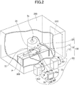
- FIG. 2 is a system configuration diagram illustrating another example of the biometric information measuring system 100 according to the first embodiment of the present invention. For the same elements as in FIG. 1 , a detailed description will be omitted.
- the biometric information measuring system 100 is a spinal cord evoked magnetic field measuring system.
- the SQUID sensor array 11 is provided facing the cervical spine of the subject P being in the supine position at the table 300 to detect the magnetic fields generated from nerve fibers in the cervical spine.
- the electrodes 40a and 40b are respectively attached to a left elbow and right elbow, and the electrical stimuli applied by the electrodes 40a and 40b induce median nerves in the left and right arms and are transmitted to the nerve fibers passing through the cervical spine.
- the median nerves, which pass through the left and right elbows, are one of the branches of the peripheral nerves that branches from the spinal cord, which is the central nerve.
- the median nerves passing through the left and right elbow are examples of multiple nerve regions that branch from the particular nerve region.
- the left elbow and the right elbow are examples of application regions to which electrical stimuli are applied at positions symmetrical to each other with respect to the central nerve, which is the branch source of the peripheral nerves.
- FIG. 2 is similar to FIG. 1 except that a positional relationship between the SQUID sensor array 11 and the subject P is different and the application regions to which the electrodes 40a and 40b are attached are different. Also in FIG. 2 , the timings of generating the electrical stimuli are set so that the phases of nerve electrical activities are matched at the junction of the nerves, which is the measurement region of the spinal cord. A method of setting the timings of generating the electrical stimuli so that the phases of nerve electrical activities are matched at the junction of nerves, which is the measurement region of the spinal cord, will be described in FIG 3 and later.
- the following description may be applied to an example in which the electrical stimuli are applied to the popliteal regions of both legs of the subject P illustrated in FIG. 1 , or to an example in which the electrical stimuli are applied to the left and right elbows of the subject P illustrated in FIG. 2 . Further, the following description is not limited to the popliteal regions and the left and right elbows, but may be applied to an example in which the electrical stimuli are applied to two nerve regions branching from the particular nerve region of the subject P (e.g., fingers of the hand).
- FIG. 3 is a functional block diagram illustrating an example of a main part of the biometric information measuring system 100 (i.e., the spinal cord evoked magnetic field measuring system) illustrated in FIGs. 1 and 2 .
- the nerve stimulating apparatus 30 includes the electrode 40a including the stimulating anode 41a and the stimulating cathode 42a, and the electrode 40b including the stimulating anode 41b and the stimulating cathode 42b.
- the nerve stimulating apparatus 30 includes only the electrodes 40a and 40b, and the electrodes 40a and 40b receiving current from the outside function as the nerve stimulating apparatus 30.
- a commercial product i.e., a general purpose product
- the data processing device 50 includes a CPU 51, a storage device 52, and a stimulation timing controller 60.
- the stimulation timing controller 60 is an example of a stimulation timing control device.
- the CPU 51 executes, for example, a measurement control program stored in the storage device 52 to control an operation of the magnetic field measuring device 10.
- the CPU 51 executes a stimulation timing setting program stored in the storage device 52 to control the stimulation timing controller 60 and sets the timings of generating the electrical stimuli generated from the electrodes 40a and 40b.
- the stimulation timing controller 60 can apply the electrical stimulus (e.g., a current pulse) to each of the electrodes 40a and 40b at any timing.
- a specification of the electrical stimulus e.g., a current value, a frequency, and a connecting duration
- the biometric information measuring system 100 has a normal measurement mode in which the electrical stimuli are applied to multiple regions of the subject P by using both electrodes 40a and 40b to diagnose a disease or the like.
- the biometric information measuring system 100 also has a pre-measurement mode in which the electrical stimulus is individually applied to the subject P by using each of the electrodes 40a and 40b to cause the SQUID sensor array 11 to measure the magnetic field before measuring the magnetic field in the normal measurement mode.
- the stimulation timing controller 60 applies the electrical stimulus only to the electrode 40a attached to the body surface of the subject P, for example, in a pre-measurement mode.
- the SQUID sensor array 11 measures a magnetic field generated from the nerve of the subject P in response to the electrical stimulus from the electrode 40a and outputs a magnetic field signal representing the measured magnetic field to the signal processing device 12.
- the signal processing device 12 performs signal processing on the magnetic field signal received from the SQUID sensor array 11 to generate magnetic field data (i.e., waveform data) and stores the generated magnetic field data in the storage device 52.
- the magnetic field data is waveform data representing temporal changes in the magnetic field strength.
- the stimulation timing controller 60 applies an electrical stimulus to the electrode 40b attached to the body surface of the subject P, for example.
- the SQUID sensor array 11 measures a magnetic field generated from the nerve of the subject P in response to the electrical stimulus from the electrode 40b and outputs a magnetic field signal representing the measured magnetic field to the signal processing device 12.
- the signal processing device 12 performs signal processing on the magnetic field signal received from the SQUID sensor array 11 to generate magnetic field data (i.e., waveform data) and stores the generated magnetic field data in the storage device 52.
- the stimulation timing controller 60 extracts feature points of the response waveforms, such as peak latency or rise latency, using the waveform data respectively generated in response to the electrical stimuli applied by the electrodes 40a and 40b.
- the peak latency is the duration from when the electrical stimuli are applied to when the magnetic field strength becomes a maximum value or a minimum value.
- the rise latency is the duration to when the magnetic field strength changes toward a maximum value, and, is for example, the duration to when the magnetic field strength changes from negative to positive (e.g., the duration until the magnetic field strength crosses zero).
- the stimulation timing controller 60 calculates latency from an application of the stimulation to a response of the central nerve (i.e., a feature point) in each of the electrodes 40a and 40b, based on a response at the measurement region measured by the magnetic field measuring device 10 in response to the stimulus at each of the application regions of the subject P.
- the peak latency and the rise latency will be described in FIGs. 4 to 7 .
- the stimulation timing controller 60 sets the timings of generating the electrical stimuli applied by the electrodes 40a and 40b so that a feature point of the response waveform corresponding to the electrode 40a and a feature point of the response waveform corresponding to the electrode 40b appear at the same time. For example, the stimulation timing controller 60 delays the timing of generating the electrical stimulus through the electrode 40 that corresponds to the response waveform in which the feature point appears earlier, thereby matching timings when the feature points appear. That is, the stimulation timing controller 60 sets the timings of generating the electrical stimuli through the electrodes 40a and 40b to timings that match timings when the feature points appear, based on the latency calculated in the pre-measurement mode.
- the timing of the electrical stimulus is also referred to as a stimulus generating timing.
- the stimulation timing controller 60 uses the timings of the electrical stimuli applied by the electrodes 40a and 40b determined in the pre-measurement mode to generate the electrical stimuli at the electrodes 40a and 40b when the magnetic fields are measured in the normal measurement mode.
- the magnetic field measuring device 10 detects magnetic fields generated by the nerves of the subject P in response to the electrical stimuli through the electrodes 40a and 40b.
- the timings of the feature points (i.e., the peak latency or the rise latency) of the magnetic field strength waveforms respectively corresponding to the electrodes 40a and 40b can be matched to each other by the stimulus generating timings set in the pre-measurement mode. Therefore, in comparison with a case in which the electrical stimulus is applied from only the single electrode 40, a large magnetic field strength can be obtained, and the measurement accuracy of the magnetic fields generated from the subject P by using the biometric information measuring system can be improved.
- the stimulation timing controller 60 may be disposed in the signal processing device 12 of the magnetic field measuring device 10 instead of the data processing device 50.
- FIG. 4 is an explanatory drawing illustrating an example of a process of the pre-measurement mode in the biometric information measuring system 100 of FIG. 3
- FIG. 5 is a waveform drawing enlarged around the peak latency of the waveform of FIG. 4
- the horizontal axis of the waveform illustrated in FIGs. 4 and 5 indicates the measurement time [ms] of the magnetic field strength measured by the SQUID sensor array 11.
- 0 ms in the measurement time indicates time at which the electrical stimulus is applied to the living body from the electrode 40.
- the vertical axis of the waveform illustrated in FIGs. 4 and 5 indicates the strength of the magnetic field (i.e., the magnetic flux density [fT]) generated by the subject P measured by the SQUID sensor array 11.
- the upper waveform in FIG. 4 illustrates an example of changes in the strength of the magnetic field measured by the SQUID sensor array 11 in response to the electrical stimulus applied from the electrode 40a attached to the subject P in the pre-measurement mode.
- the lower waveform in FIG. 4 illustrates an example of changes in the strength of the magnetic field measured by the SQUID sensor array 11 in response to the electrical stimulus applied from the electrode 40b attached to the subject P in the pre-measurement mode. That is, FIG. 4 illustrates the magnetic field measurement data obtained by the SQUID sensor array 11 in response to the electrical stimuli applied from the electrodes 40a and 40b.
- the upper waveform in FIG. 4 and the lower waveform in FIG. 4 are aligned with respect to the time axis, but the magnetic field is measured at different times. That is, the measurement of the magnetic field for obtaining the upper waveform of FIG. 4 and the lower waveform of FIG. 4 is performed by generating the electrical stimulus through each of the electrodes 40a and 40b at different timings.
- the CPU 51 displays the two waveform data vertically arranged on the display device 50a with a dashed line indicating the time range and a dashed line indicating the peak latency as illustrated in FIG. 4 .
- the electrode 40a is attached to the popliteal region of the left leg of the subject P, the electrical stimulus from the electrode 40a excites the sciatic nerve of the left leg, and the nerve activity is transmitted to the spinal cord.
- the electrode 40b is attached to the popliteal region of the right leg of the subject P, the electrical stimulus from the electrode 40b excites the sciatic nerve of the right leg, and the nerve activity is transmitted to the spinal cord.
- the electrode 40a is attached to the left elbow of the subject P, the electrical stimulus from the electrode 40a excites the median nerve of the left arm, and the nerve activity is transmitted to the spinal cord.
- the electrode 40b is attached to the right elbow of the subject P, the electrical stimulus from the electrode 40b excites the median nerve in the right arm, and the nerve activity is transmitted to the spinal cord.
- the stimulation timing controller 60 can calculate measurement time of peaks (i.e., a peak value on a positive side) in which the height of each of two waveforms included in a predetermined time range is maximum, as peak latency TLt and TRt.
- the peak latency TLt and TRt is the duration from when the electrical stimulus is applied to when the peak of the waveform appears and depends on the distance between the application region of stimulation and the measurement region of the magnetic field.
- the timings when the peak latency TLt and TRt appear can be matched by adjusting timings of generating the electrical stimuli from the electrodes 40a and 40b.
- the "predetermined time range" illustrated in FIG. 4 is set to exclude, from the calculation of the peak latency TLt and TRt, a noise waveform (e.g., around 0 ms) generated by the electrical stimuli applied to the subject P from the electrodes 40a and 40b.
- the predetermined time range is set by an operator of the biometric information measuring system 100 by specifying a time range of the measurement waveform displayed on the display device 50a by using an input device, such as a mouse.
- the predetermined time range may be automatically set by a program executed by the CPU 51.
- the distance from the application region to which the electrical stimulus is applied to the measurement region of the magnetic field approximately depends on the height of the subject P and the length of the legs of the subject P. Therefore, the CPU 51 can automatically set the time range based on the height of the subject P and the length of the legs of the subject P input from the input device, such as a keyboard, by an operator or the like.
- the time range may be estimated by the CPU 51 by accumulating information such as the height and the length of the legs of other subjects P of whom the magnetic field has been measured in the past and a combination of the time range and the peak latency, and using the accumulated information.
- the estimation of the time range may be performed using machine learning techniques. By using information about magnetic field measurement in the past, the accuracy of time range setting can be improved in comparison with simply setting the time range using a calculation formula.
- the stimulation timing controller 60 determines that the peak latency TLt and TRt match when a shift between the peak latency TLt and TRt is, for example, 0.1 ms or smaller.
- a threshold of the shift used to determine whether the peak latency TLt and TRt match is not limited to 0.1 ms, but may be 0.05 ms or 0.01 ms, for example.
- the threshold is greater than or equal to minimum setting time for a difference in generating the electrical stimuli through the electrodes 40a and 40b that can be set by the nerve stimulating apparatus 30.
- the minimum time for the difference in generating the electrical stimuli set by the nerve stimulating apparatus 30 is 0.01 ms.
- the stimulation timing controller 60 delays the timing of generating the electrical stimulus generated from one of the electrodes 40a and 40b in order to match the timings when the peak latency TLt and the peak latency TRt appear.
- the stimulation timing controller 60 determines to delay the stimulus generating timing of the electrode 40a by the time difference between the peak latency TLt and the peak latency TRt when the peak latency TLt is earlier than the peak latency TRt. In the example of FIG. 5 , it is determined that the timing of the electrical stimulus generated from the electrode 40a is delayed by 0.2 ms relative to the timing of the electrical simulation generated from the electrode 40b.
- the stimulation timing controller 60 determines to delay the stimulus generating timing of the electrode 40b by the time difference between the peak latency TLt and the peak latency TRt when the peak latency TRt is earlier than the peak latency TLt, for example.
- the stimulation timing controller 60 determines to use the stimulus generating timings of the electrodes 40a and 40b used in the pre-measurement mode, in the normal measurement mode.
- the stimulation timing controller 60 uses the determined stimulus generating timings in the normal measurement mode. That is, the stimulation timing controller 60 sets the stimulus generating timings of the electrodes 40a and 40b so as to cause the peak latency TLt and peak latency TRt to be at the same time, based on the latency calculated for each of the electrodes 40a and 40b in the pre-measurement mode.
- FIG. 6 is an explanatory drawing illustrating another example of the process of the pre-measurement mode in the biometric information measuring system illustrated in FIG. 3 .
- the detailed description will be omitted.
- the stimulation timing controller 60 calculates measurement time at rising when the strength of the magnetic field of each of two waveforms included in the predetermined time range changes from negative to positive as the latency TLt and the latency TRt. Then, the stimulation timing controller 60 delays a timing of the electrical stimulus generated from one of the electrodes 40a and 40b in order to match timings when the rise latency TLt and the rise latency TRt appear in accordance with the time difference between the rise latency TLt and the rise latency TRt, similarly with FIG. 4 .
- the set stimulus generating timing is used in the normal measurement mode.
- the stimulus generating timings of the electrodes 40a and 40b used in the pre-measurement mode are used in the normal measurement mode.
- the CPU 51 displays the two waveforms data vertically on the display device 50a with a dashed line indicating the time range and a dashed line indicating the rise latency.
- FIG. 7 is an explanatory drawing illustrating yet another example of the process of the pre-measurement mode in the biometric information measuring system 100 of FIG. 3 .
- the detailed description will be omitted.
- the stimulation timing controller 60 calculates measurement time of a peak (i.e., a peak value on a negative side) in which the height of each of the two waveforms included in the predetermined time range is the smallest, as the peak latency TLt and the peak latency TRt. Then, the stimulation timing controller 60 sets the stimulus generating timings of the electrodes 40a and 40b in order to match timings of the peak latency TLt and the peak latency TRt in accordance with the time difference between the peak latency TLt and the peak latency TRt as in FIG. 4 . The set stimulus generating timings are used in the normal measurement mode. Similarly with the description of FIG. 4 , when the peak latency TLt and the peak latency TRt match in the pre-measurement mode, the stimulus generating timings of the electrodes 40a and 40b used in the pre-measurement mode are used in the normal measurement mode.
- a peak i.e., a peak value on a negative side
- the stimulation timing controller 60 sets the stimulus
- the CPU 51 displays the two waveforms data vertically on the display device 50a with a dashed line indicating the time range and a dashed line indicating the peak latency.
- whether the latency is a peak latency or a rise latency may be determined in accordance with an environment in which the magnetic field is measured. For example, when a signal-to-noise ratio (SN ratio) decreases because measured environmental magnetic field (i.e., artifact) is larger than the strength of the biomagnetic field, it is preferable to obtain a temporal feature amount of the waveform at the peak latency. Calculation of the latency by using the rise latency is a method commonly used in the field of electrophysiology.
- SN ratio signal-to-noise ratio
- the biometric information measuring system 100 may be provided with a manual setting mode and the peak latency or the rise latency may be specified by an operator or the like viewing the display device 50a on which two waveforms of the magnetic field are displayed.
- the peak latency or the rise latency may be adjusted by the operator using a mouse or the like to move the dashed line indicating the peak latency or the rise latency calculated by the stimulation timing controller 60 and displayed on the display device 50a in the time axis direction.
- the waveform displayed on the display device 50a may be enlarged in the time axis direction.
- FIG. 8 is a flowchart illustrating an example of a measurement operation of a magnetic field in the biometric information measuring system 100 in FIG. 3 .
- steps S10, S12, S14, and S16 depict an example of a method of setting the stimulus generating timing of the biometric information measuring system, and the CPU 51 and the stimulation timing controller 60 cooperate in the pre-measurement mode to perform the method.
- step S10 the biometric information measuring system 100 respectively generates the stimuli on the electrodes 40a and 40b as described above and measures the magnetic fields in the pre-measurement mode.
- step S12 the biometric information measuring system 100 calculates the latency for each of the electrodes 40a and 40b by using any one of the methods illustrated in FIG. 4 , FIG. 6 , or FIG. 7 based on magnetic field measurement results in step S10.
- step S14 the biometric information measuring system 100 determines whether latency corresponding to the electrode 40a and latency corresponding to the electrode 40b match. When the latency matches, the biometric information measuring system 100 performs step S18. When the latency does not match, the biometric information measuring system 100 performs step S16. As described above, matching/non-matching is determined, for example, by whether the latency difference is 0.1 ms or smaller.
- step S16 the biometric information measuring system 100 sets the generating timings of generating the electrical stimuli at the electrodes 40a and 40b so that the feature points of the waveforms appear at the same time, and performs step S18.
- the stimulus generating timing is adjusted by delaying the stimulus generating timing of the electrode 40 corresponding to early latency shifted by the latency difference. That is, the stimulus generating timing of only one of the electrodes 40a and 40b is delayed.
- step S14 and step S16 by adjusting the stimulus generating timing, the magnetic fields generated from the spinal cord or the like can be accurately overlapped in response to the electrical stimuli applied from the electrodes 40a and 40b, thereby increasing the magnetic field strength.
- This can prevent the magnetic field strength from being weakened even when positions on the skin of the subject P to which the electrodes 40a and 40b attached are shifted from ideal positions. In other words, the positions on the skin of the subject P to which the electrodes 40a and 40b are attached may not be required to be precisely determined, thus the workability of the preparation before measuring the magnetic field can be improved.
- step S18 the biometric information measuring system 100 transitions from the pre-measurement mode to the normal measurement mode, and applies the electrical stimuli to the subject P from the electrodes 40a and 40b to measure the magnetic field generated by the subject P. Then, the measurement operation of the biomagnetic field performed by the biometric information measuring system 100 is terminated.
- step S18 when the magnetic field strength is lowered while repeatedly applying the electrical stimuli to the subject P to measure the magnetic field, the electrode 40 attached to the application region may be misaligned due to the movement of the subject P on the table 300. In this case, the measurement operation of the magnetic field may be stopped once, and the process illustrated in FIG. 8 may be performed again.
- FIG. 9 is a waveform drawing illustrating an example of temporal changes in the strength of a magnetic field signal in one-side stimulus and two-side concurrent stimuli in the biometric information measuring system 100 of FIG. 3 .
- the one-side stimulus illustrates a waveform obtained when the electrical stimulus is applied to the subject P by using one of the electrodes 40a and 40b.
- the two-side concurrent stimuli illustrate a waveform obtained when the electrical stimuli are applied simultaneously to the subject P from the electrodes 40a and 40b using the stimulus generating timing determined in the pre-measurement mode, in the normal measurement mode.
- the waveforms of the magnetic field illustrated in FIG. 9 for example, are overlapped by the magnetic fields measured by multiple SQUIDs of the SQUID sensor array 11.
- the strength of the magnetic field (i.e., 400 fT) obtained by the two-side concurrent stimuli is approximately twice the strength of the magnetic field (i.e., 180 fT) obtained by the one-side stimulus. That is, it is found that by using the stimulus generating timing determined in the pre-measurement mode to generate the electrical stimuli from the electrodes 40a and 40b, the measured strength of the magnetic field is increased. Therefore, when the application region is away from the measurement region, such as when the electrical stimulus is applied to the popliteal region to measure a magnetic field generated by the thoracic spinal cord, the magnetic field strength being measured can be increased relative to a conventional method. As a result, it is possible to measure the magnetic field at the measurement region at which the measurement is difficult using a conventional method.
- the stimulus generating timings of the electrodes 40a and 40b are set based on response results of a particular nerve region in response to the stimulus applied to each of multiple nerve regions branching from the particular nerve region.
- the stimulus generating timings of the electrodes 40a and 40b are set based on a measurement result of the magnetic field generated from the particular region of the central nerve in response to the electrical stimulus applied to each of multiple nerve regions of the peripheral nerves branching from the spinal cord (i.e., the central nerve).
- the strength of the magnetic field generated from the spinal cord where the nerve fibers join can be increased.
- This enables the SQUID sensor array 11 to obtain a larger magnetic field strength generated by the nerve activity in comparison with a case of applying the electrical stimulus to the nerve fiber at a single region. That is, a timing of generating the stimuli to the living body that can increase the strength of the nerve activity of the living body can be set.
- the correct latency can be determined regardless of the shape of the waveform. This can accurately set the stimulus generating timings of the electrodes 40a and 40b to match the timings at which the feature points appear.
- the magnetic field strength can be further increased because the timings at which the feature points appear can accurately match.
- the magnetic field strength can also be prevented from being weakened when positions on the skin of the subject P to which the electrodes 40a and 40b are attached are shifted from the ideal positions.
- the positions of the electrodes 40a and 40b on the skin of the subject P may not be required to be precisely determined, and the workability of the preparation before measuring the magnetic field can be improved.
- an existing nerve stimulating apparatus 30 can be used to apply the electrical stimuli to the electrodes 40a and 40b at timings that increase the magnetic field strength.
- a commercially available nerve stimulating apparatus 30 can be used to reduce the cost of the biometric information measuring system 100.
- FIG. 10 is a functional block diagram of a biometric information measuring system according to a second embodiment of the present invention.
- a biometric information measuring system 100A illustrated in FIG. 10 includes the magnetic field measuring device 10, a nerve stimulating apparatus 30A, a data processing device 50A, and the display device 50a.
- a system configuration of the biometric information measuring system 100A is similar to the system configuration of FIG. 1 or FIG. 2 .
- the data processing device 50A has a configuration and function similar to the data processing device 50 except that the stimulation timing controller 60 is removed from the data processing device 50 illustrated in FIG. 3 .
- the nerve stimulating apparatus 30A has a configuration and function similar to the nerve stimulating apparatus 30 except that the stimulation timing controller 60 is added to the nerve stimulating apparatus 30 illustrated in FIG. 3 .
- a flow of a magnetic field measurement operation performed by the biometric information measuring system 100A is similar to the flow of FIG. 8 .
- the latency which is a feature point of the magnetic field waveform, is calculated using any one of the methods described with reference to FIG. 4 , FIG. 6 , or FIG. 7 .
- An example of temporal changes in the signal strength is similar to the example in FIG. 9 .
- the magnetic field strength generated by the subject P can be increased, as in the first embodiment described above.
- the stimulation timing controller 60 is included in the nerve stimulating apparatus 30A so that generating timings of generating the electrical stimuli generated from the electrodes 40a and 40b can be set using an existing data processing device 50A.
- FIG. 11 is a functional block diagram of a biometric information measuring system according to a third embodiment of the present invention.
- a biometric information measuring system 100B illustrated in FIG. 11 includes the magnetic field measuring device 10, a nerve stimulating apparatus 30B, a data processing device 50B, and the display device 50a.
- a system configuration of the biometric information measuring system 100B is similar to the system configuration of FIG. 1 or FIG. 2 .
- the data processing device 50B has a configuration and function similar to the data processing device 50 except that a generating timing calculating unit 61 and a trigger signal generator 62 are included instead of the stimulation timing controller 60 of the data processing device 50 illustrated in FIG. 3 .
- the nerve stimulating apparatus 30B has a configuration and function similar to the nerve stimulating apparatus 30 except that an external trigger signal input unit 63 and a current supplying unit 64 are added to the nerve stimulating apparatus 30 illustrated in FIG. 3 .
- the generating timing calculating unit 61 and the trigger signal generator 62 are examples of the stimulation timing controller and are examples of the stimulation timing control device.
- the generating timing calculating unit 61 operates in the pre-measurement mode and calculates latency until a response (a feature point) from the measurement region is generated in response to the electrical stimuli respectively applied from the electrodes 40a and 40b to the application regions of the subject P.
- the generating timing calculating unit 61 performs processing similar to the processing of steps S12, S14, and S16 illustrated in FIG. 8 .
- the latency is the peak latency or the rise latency, as described in FIGs. 4 , 6 or 7 .
- the generating timing calculating unit 61 sets timings of generating the stimuli at the electrodes 40a and 40b so that the feature points of two response waveforms corresponding to the electrodes 40a and 40b appear at the same time.
- a function of the generating timing calculating unit 61 is similar to the function of the stimulation timing controller 60 described with reference to the function of FIG. 3 excluding the function of generating electrical stimulus to the electrodes 40a and 40b.
- a stimulus generating timing calculated by the generating timing calculating unit 61 is stored in the storage device 52.
- the stimulus generating timing stored in the storage device 52 includes delay electrode information indicating the electrode 40 that delays the generation of the electrical stimulus and delay time information indicating delay time of the electrical stimulus of the other electrode 40 relative to the one electrode 40.
- the trigger signal generator 62 is connected to the external trigger signal input unit 63 of the nerve stimulating apparatus 30B through the signal line 74 and outputs a trigger signal to the external trigger signal input unit 63.
- the trigger signal output by the trigger signal generator 62 includes at least one of application electrode information, delay electrode information, delay time information, or an application start instruction.
- the application electrode information indicates the electrode 40 that generates the electrical stimulus.
- the application electrode information indicates one of the electrodes 40a and 40b in the pre-measurement mode and both of the electrodes 40a and 40b in the normal measurement mode. When the application electrode information indicates one of the electrodes 40a and 40b, delay electrode information and delay time information are not used.
- the application start instruction indicates a start instruction of applying the electrical stimulus (a start instruction of applying the electrical stimulus as an original trigger signal).
- the trigger signal generator 62 In the pre-measurement mode, the trigger signal generator 62 outputs the application electrode information indicating one of the electrodes 40a and 40b as a trigger signal to the external trigger signal input unit 63 before the CPU 51 outputs a measurement start instruction. At this time, the trigger signal generator 62 may output dummy delay electrode information and dummy delay time information to the external trigger signal input unit 63.
- the trigger signal generator 62 outputs the application electrode information, the delay electrode information, and the delay time information stored in the storage device 52 as the trigger signal to the external trigger signal input unit 63 before the CPU 51 outputs the measurement start instruction.
- the trigger signal generator 62 outputs the application start instruction as the trigger signal to the external trigger signal input unit 63 based on the measurement start instruction received through an input device (which is not illustrated) connected to the data processing device 50A in the pre-measurement mode and the normal measurement mode.
- the measurement start instruction is generated by an input device, such as a mouse or a keyboard, being operated by an operator or the like operating the biometric information measuring system 100B.
- the external trigger signal input unit 63 decodes the trigger signal received through the signal line 74 and performs an operation according to a decoded result.
- the external trigger signal input unit 63 stores the application electrode information, the delay electrode information, or the delay time information, which is received, in an internal register provided in the nerve stimulating apparatus 30B or the like.
- the external trigger signal input unit 63 outputs a start timing signal indicating a start of an application to the current supplying unit 64.
- the current supplying unit 64 supplies a predetermined current to only one of the electrodes 40 indicated by the application electrode information to generate the electrical stimulus.
- the current supplying unit 64 When receiving the application start instruction in a state in which the application electrode information indicating both electrodes 40a and 40b is stored in the internal register, the current supplying unit 64 reads out the delay electrode information and the delay time information from the internal register. The current supplying unit 64 outputs a predetermined current to the electrodes 40a and 40b simultaneously to generate the electrical stimulus when the delay time information indicates "0 ms".
- the current supplying unit 64 When the read-out delay time information indicates a value other than "0 ms", the current supplying unit 64 first outputs a predetermined current to one electrode 40 that is not an electrode 40 indicated by the delay electrode information and generates the electrical stimulus. Then, the current supplying unit 64 outputs a predetermined current to the other electrode 40 indicated by the delay electrode information to generate the electrical stimulus after a delay time indicated by the delay time information has passed from when the current supplying unit 64 outputs the predetermined current to the one electrode 40.
- the current supplying unit 64 may read out the application electrode information, the delay electrode information, and the delay time information from the internal register in response to receiving the application start instruction.
- the current supplying unit 64 may read out the application electrode information, the delay electrode information, and the delay time information from the internal register in advance before receiving the application start instruction.
- the nerve stimulating apparatus 30B notifies the magnetic field measuring device 10 of the generation of the electrical stimulus in synchronization with the generation of the electrical stimulus from the electrode 40.
- the nerve stimulating apparatus 30B notifies the magnetic field measuring device 10 of the generation of the electrical stimulus in synchronization with the generation of the electrical stimulus from the electrode 40 that generates the electrical stimulus earlier.
- the nerve stimulating apparatus 30B does not notify the magnetic field measuring device 10 of the generation of the electrical stimulus in synchronization with the generation of the electrical stimulus from the electrode 40 that generates the electrical stimulus later.
- the magnetic field measuring device 10 starts measuring the magnetic field by using the SQUID sensor array 11 in response to a notification from the nerve stimulating apparatus 30B and generates magnetic field data by processing the measured magnetic field signal by using the signal processing device 12.
- the data processing device 50B may notify the magnetic field measuring device 10 of the generation of the electrical stimulus from the electrode 40 in response to the application start instruction.
- the delay time information indicating the delay time of each of the electrodes 40a and 40b relative to a reference timing may be used.
- the delay time of the electrode 40a and the delay time of the electrode 40b indicated by the delay time information are both set to "0 ms".
- the current supplying unit 64 causes the electrode 40 indicated by the application electrode information to generate the electrical stimulus in response to the application start instruction.
- the delay time of one electrode 40 is set to "0 ms" and the delay time of the other electrode 40 is set to a value indicating delay time of the electrical stimulus of the other electrode 40 relative to the one electrode 40.
- the above operation enables the nerve stimulating apparatus 30B to generate the electrical stimuli at the electrodes 40a and 40b in response to the application start instruction from the trigger signal generator 62 without recognizing the pre-measurement mode and the normal measurement mode.
- a commercial product i.e., a general purpose product
- a flow of a magnetic field measurement operation performed by the biometric information measuring system 100B is similar to the flow of FIG. 8 .
- the generating timing calculating unit 61 and the trigger signal generator 62 may be disposed in the signal processing device 12 of the magnetic field measuring device 10 instead of the data processing device 50B.
- An example of temporal changes in the signal strength is similar to the example in FIG. 9 .
- the magnetic field strength generated by the subject P can be increased in the third embodiment as in the first embodiment described above.
- the external trigger signal input unit 63 can cause the current supplying unit 64 to output an electrical current to the electrode 40 in response to the trigger signal generated by the trigger signal generator 62.
- This enables the nerve stimulating apparatus 30B to generate the electrical stimulus at the electrode 40 in response to the trigger signal output from the trigger signal generator 62 without recognizing the pre-measurement mode and the normal measurement mode.
- a commercially available nerve stimulating apparatus 30B can be used to reduce the cost of the biometric information measuring system 100B.
- FIG. 12 is a functional block diagram of a biometric information measuring system according to a fourth embodiment of the present invention.
- a biometric information measuring system 100C illustrated in FIG. 12 includes the magnetic field measuring device 10, a nerve stimulating apparatus 30C, the data processing device 50A, and the display device 50a.
- a system configuration of the biometric information measuring system 100C is similar to the system configuration of FIG. 1 or FIG. 2 .
- the nerve stimulating apparatus 30C has a configuration and function similar to the configuration and function of the nerve stimulating apparatus 30B, except that the generating timing calculating unit 61 and the trigger signal generator 62 are added to the nerve stimulating apparatus 30B illustrated in FIG. 11 . That is, in the present embodiment, the existing data processing device 50A can be used to perform the operation of the pre-measurement mode and the operation of the normal measurement mode using the stimulus generating timing that has been set in the pre-measurement mode.
- the CPU 51 In the pre-measurement mode, the CPU 51 outputs an instruction to simultaneously generate the electrical stimuli at the electrodes 40a and 40b to the trigger signal generator 62 through the generating timing calculating unit 61 of the nerve stimulating apparatus 30C.
- the CPU 51 causes the generating timing calculating unit 61 of the nerve stimulating apparatus 30C to calculate the stimulus generating timings of the electrodes 40a and 40b used in the normal measurement mode.
- a function of the generating timing calculating unit 61 is similar to the function of the generating timing calculating unit 61 described with reference to FIG. 11 .
- the generating timing calculating unit 61 of the present embodiment has a function to read the magnetic field data measured in the pre-measurement mode from the storage device 52 and a function to store the calculated stimulus generating timing in the storage device 52.
- the calculated stimulus generating timing may be stored in a register or a memory, which are not illustrated, provided in the nerve stimulating apparatus 30C.
- the trigger signal generator 62 Functions of the trigger signal generator 62, the external trigger signal input unit 63, and the current supplying unit 64 are similar to the functions of the trigger signal generator 62, the external trigger signal input unit 63, and the current supplying unit 64 illustrated in FIG. 11 , respectively.
- the trigger signal generator 62 outputs the trigger signal to the external trigger signal input unit 63 in response to the measurement start instruction from the CPU 51 received through the signal line 74.
- a flow of the magnetic field measurement operation performed by the biometric information measuring system 100C is similar to the flow of FIG. 8 .
- the latency which is the feature point of the magnetic field waveform, is calculated using any one of the methods illustrated in FIG. 4 , FIG. 6 , and FIG. 7 .
- An example of temporal changes in the signal strength is similar to the example in FIG. 9 .
- the magnetic field strength generated by the subject P can be increased as in the above-described embodiments.
- the existing data processing device 50A can be used to perform the operation of the pre-measurement mode and the operation of the normal measurement mode using the stimulus generating timings set in the pre-measurement mode.
- FIG. 13 is a functional block diagram of a biometric information measuring system according to a fifth embodiment of the present invention.
- a biometric information measuring system 100D illustrated in FIG. 13 includes the magnetic field measuring device 10, a nerve stimulating apparatus 30D, a data processing device 50D, and the display device 50a.
- a system configuration of the biometric information measuring system 100D is similar to the system configuration of FIG. 1 or FIG. 2 .
- the data processing device 50D includes a generating timing calculating unit 61D and a trigger signal generator 62D instead of the generating timing calculating unit 61 and the trigger signal generator 62 of the data processing device 50B illustrated in FIG. 11 .
- Other components and functions of the data processing device 50D are similar to the components and functions of the data processing device 50B.
- the generating timing calculating unit 61D and the trigger signal generator 62D are examples of the stimulation timing control device.
- the nerve stimulating apparatus 30D has a configuration and function similar to the configuration and function of the nerve stimulating apparatus 30B except that the external trigger signal input unit 63D and the current supplying unit 64D are included instead of the external trigger signal input unit 63 and the current supplying unit 64 of the nerve stimulating apparatus 30B illustrated in FIG. 11 .
- the trigger signal generator 62D and the external trigger signal input unit 63D are connected through signal lines 74 corresponding to the electrodes 40a and 40b respectively.
- the external trigger signal input unit 63D and the current supplying unit 64D are connected through signal lines corresponding to the electrodes 40a and 40b respectively.
- the generating timing calculating unit 61D calculates the stimulus generating timings of the electrodes 40a and 40b so that the feature points of two response waveforms corresponding to the electrodes 40a and 40b appear at the same time.
- an operation performed until the stimulus generating timings of the electrodes 40a and 40b are calculated is similar to the operation of the generating timing calculating unit 61 described with reference to FIG. 11 .
- the generating timing calculating 1D stores the calculated stimulus generating timings of the electrodes 40a and 40b in the storage device 52.
- the trigger signal generator 62D successively generates a trigger signal that generates the electrical stimulus at each of the electrodes 40a and 40b, and successively outputs the generated trigger signal to the nerve stimulating apparatus 30D by using the signal lines 74 that are different from each other.
- the trigger signal generator 62D does not need to generate a trigger signal identifying the electrodes 40a and 40b.
- the trigger signal generator 62D outputs a pair of trigger signals to generate the electrical stimuli at the electrodes 40a and 40b to the external trigger signal input unit 63D in the normal measurement mode according to the stimulus generating timings of the electrodes 40a and 40b stored in the storage device 52.
- the external trigger signal input unit 63D When receiving the trigger signal through the signal line 74 corresponding to the electrode 40a, the external trigger signal input unit 63D outputs the start timing signal indicating the application start to the current supplying unit 64D through the signal line corresponding to the electrode 40a. When receiving the trigger signal through the signal line 74 corresponding to electrode 40b, the external trigger signal input unit 63D outputs the start timing signal indicating the application start to the current supplying unit 64D through the signal line corresponding to electrode 40b.
- the current supplying unit 64D supplies a predetermined current to the electrode 40 corresponding to the signal line through which the start timing signal is received to generate the electrical stimulus. This enables the trigger signal generator 62D, the external trigger signal input unit 63D, and the current supplying unit 64D to generate the electrical stimuli at the electrodes 40a and 40b without using the application electrode information, the delay electrode information, and the delay time information. In other words, by outputting only a trigger signal indicating the application start instruction from the trigger signal generator 62D to the external trigger signal input unit 63D, the electrical stimuli can be generated at the electrodes 40a and 40b.
- a commercial product i.e., a general purpose product
- the nerve stimulating apparatus 30D operates in response to the trigger signal indicating the application start indication.
- the generating timing calculating unit 61D and the trigger signal generator 62D may be disposed in the signal processing device 12 of the magnetic field measuring device 10 instead of the data processing device 50D.
- the magnetic field strength generated by the subject P can be increased as in the above-described embodiments.
- the nerve stimulating apparatus 30D can generate the electrical stimulus at each of the electrodes 40a and 40b in response to a corresponding one of the trigger signals of the electrodes 40a and 40b output by the trigger signal generator 62D. This enables, for example, the commercially available nerve stimulating apparatus 30D to be used to reduce the cost of the biometric information measuring system 100D.
- FIG. 14 is a functional block diagram of a biometric information measuring system according to a sixth embodiment of the present invention.
- a biometric information measuring system 100E illustrated in FIG. 14 includes the magnetic field measuring device 10, a nerve stimulating apparatus 30E, the data processing device 50A, and the display device 50a.
- a system configuration of the biometric information measuring system 100E is similar to the system configuration of FIG. 1 or FIG. 2 .
- the nerve stimulating apparatus 30E has a configuration and function similar to the configuration and function of the nerve stimulating apparatus 30D, except that the generating timing calculating unit 61D and the trigger signal generator 62D are added to the nerve stimulating apparatus 30D illustrated in FIG. 13 . That is, in the present embodiment, the existing data processing device 50A can be used to perform the operation of the pre-measurement mode and the operation of the normal measurement mode using the stimulus generating timings set in the pre-measurement mode.
- a function of the generating timing calculating unit 61D is similar to the function of the generating timing calculating unit 61D described with reference to FIG. 13 .
- the generating timing calculating unit 61D of the present embodiment has a function to read the magnetic field data measured in the pre-measurement mode from the storage device 52 and a function to store the calculated stimulus generating timing in the storage device 52.
- the calculated stimulus generating timing may be stored in a register or a memory, which are not illustrated, provided in the nerve stimulating apparatus 30E.
- the trigger signal generator 62D Functions of the trigger signal generator 62D, the external trigger signal input unit 63D, and the current supplying unit 64D are similar to the functions of the trigger signal generator 62D, the external trigger signal input unit 63D, and the current supplying unit 64D illustrated in FIG. 13 respectively.
- the trigger signal generator 62D outputs the trigger signal to the external trigger signal input unit 63D in response to the measurement start instruction received from the CPU 51 through the signal line 74.
- a flow of a magnetic field measurement operation performed by the biometric information measuring system 100E is similar to the flow of FIG. 8 .
- the latency which is the feature point of the magnetic field waveform, is calculated using any one of the methods illustrated in FIG. 4 , FIG. 6 , and FIG. 7 .
- An example of temporal changes in the signal strength is similar to the example in FIG. 9 .
- the magnetic field strength generated by the subject P can be increased as in the above-described embodiments.
- the existing data processing device 50A can be used to perform the operation of the pre-measurement mode and the operation of the normal measurement mode using the stimulus generating timings set in the pre-measurement mode .
- FIG. 15 is a functional block diagram of a biometric information measuring system according to a seventh embodiment of the present invention.
- a biometric information measuring system 100F illustrated in FIG. 15 includes the magnetic field measuring device 10, two nerve stimulating apparatuses 30F and 30G, the data processing device 50D, and the display device 50a.
- a system configuration of the biometric information measuring system 100F is similar to the system configuration of FIG. 1 or FIG. 2 .
- the nerve stimulating apparatus 30F includes the external trigger signal input unit 63, the current supplying unit 64, and the electrode 40a.
- the nerve stimulating apparatus 30G includes the external trigger signal input unit 63, the current supplying unit 64, and the electrode 40b.
- the nerve stimulating apparatuses 30F and 30G are examples of a sub-stimulator, and two sub-stimulators constitute a nerve stimulating apparatus in the present embodiment.
- the trigger signal generator 62D successively generates a trigger signal that generates the electrical stimulus at each of the electrodes 40a and 40b and successively outputs the generated trigger signal to the external trigger signal input unit 63 of each of the nerve stimulating apparatuses 30F and 30G.
- the trigger signal generator 62D is connected to the external trigger signal input unit 63 of the nerve stimulating apparatuses 30F and 30G through the respective signal lines 74 different from each other.
- Each of the external trigger signal input units 63 of the nerve stimulating apparatus 30F and 30G outputs the start timing signal indicating the application start to the corresponding current supplying unit 64 in response to the trigger signal received from the trigger signal generator 62D.
- the nerve stimulating apparatuses 30F and 30G independently generate the electrical stimuli at the electrodes 40a and 40b.
- commercial products i.e., general purpose products
- a flow of a magnetic field measurement operation performed by the biometric information measuring system 100F is similar to the flow of FIG. 8 .
- the latency which is the feature point of the magnetic field waveform, is calculated using any one of the methods illustrated in FIG. 4 , FIG. 6 , and FIG. 7 .
- An example of temporal changes in the signal strength is similar to the example in FIG. 9 .
- each of the nerve stimulating apparatuses 30F and 30G can generate the electrical stimulus at the corresponding electrode 40 (i.e., 40a or 40b) in response to the trigger signal output by the trigger signal generator 62D for each of the electrodes 40a and 40b.
- the nerve stimulating apparatuses 30, 30A, 30B, 30C, 30D, 30E, 30F, and 30G may generate the electrical stimuli (i.e., the current pulses) from the electrodes 40a and 40b.
- the nerve stimulating apparatuses 30, 30A, 30B, 30D, 30E, 30F, and 30G may generate magnetic stimuli, acoustic stimuli, or mechanical stimuli, and may include needle-like electrodes 40 inserted into the skin.
- the stimulus generating timings can be set in the pre-measurement mode so that response timings, at a particular nerve region, such as the spinal cord, with respect to the stimuli match.
- timing of generating the stimulus is adjusted so that the response timings, at a particular nerve region, such as the spinal cord, with respect to the electrical stimuli generated from the two electrodes 40a and 40b match, to measure the magnetic field.
- stimulus generating timings may be adjusted so that response timings at the spinal cord with respect to the electrical stimuli generated from three or more electrodes 40 match, and three or more responses may be overlapped.
- Three or more stimuli may be magnetic, acoustic, or mechanical.
- the electrical stimuli are applied to the popliteal regions of the both legs or the left and right elbows to measure the magnetic field generated from a particular nerve region, such as the spinal cord.
- the stimuli may be applied to the index and middle fingers of the left or right hand to measure the magnetic field generated by the median nerve of the palm or the arm corresponding to the fingers to which the stimuli have been applied.
- the stimuli may be applied to three or more fingers or to at least one finger of the left and right hands.
- the latency may be calculated using not only the magnetic field measurement data, but also current data estimated (i.e., reconstructed) based on the magnetic field measurement data. That is, application timings of the electrical stimuli generated by two electrodes 40a and 40b may be adjusted using latency calculated from the current data.
- FIG. 16 illustrates an example of calculating latency by using current data estimated based on the magnetic field measurement data in the pre-measurement mode of the biometric information measuring system described above.
- current intensity waveforms illustrated in FIG. 16 are results of calculating current distribution waveforms of the nerve electrical activities at a position between the L2 vertebral body and the L3 vertebral body (i.e., the intervertebral space) based on the neural activities of the sciatic nerves caused by electrical stimuli from the left and right legs.
- the peak latency which is peak time of the current waveform, may be the feature amount.
- the magnetic field is a component waveform of X, Y, or Z (i.e., a direction in three dimensions), and, for example, if an SN ratio on the X-axis was poor, it would be difficult to detect a temporal feature amount.
- the current data is calculated by performing estimation (i.e., current reconstruction) based on the three components of X, Y, and Z, and it is possible to obtain a waveform having a good SN ratio, and it is advantageous to adjust the timings more accurately.
- an electric potential measuring device may be used to obtain a feature point of an electric potential waveform obtained at the L3 vertebral body (i.e., the thoracic spine) before measuring the neuromagnetic field.
- FIG. 17 is a system configuration diagram illustrating an example of a biometric information measuring system according to an eighth embodiment of the present invention.
- a biometric information measuring system 100G illustrated in FIG. 17 the timings of the electrical stimuli applied from the nerve stimulating apparatus 30 are adjusted using a feature point of an electric potential waveform measured in the pre-measurement mode.
- the same reference numerals will be used and the detailed description will be omitted.
- an electric potential measuring device 80 that can measure the electric potential difference at the particular region of the living body is added to the configuration of FIG. 1 as a biometric information measuring apparatus in addition to the magnetic field measuring device 10.
- electrodes 40c i.e., recording electrodes for recording the electric potential (a pair of anode and cathode)) of the electric potential measuring device 80 are attached to the skin of the lumbar spine of the subject P (e.g., the L3 vertebral body), and the sciatic nerves of the legs of the subject P are excited by the electrical stimuli applied at the electrodes 40a and 40b attached to the popliteal region of both legs, for example.
- the electrical stimuli of the electrodes 40a and 40b transmit the nerve activity of the subject P to the central nerve, and an electric potential waveform based on the nerve activity is measured between the electrodes 40c of the electric potential measuring device 80 for detecting the electric potential.
- Electric potential measurement data is stored in the electric potential measuring device 80 and is used. More preferably, the electric potential measurement data is transferred to the data processing device 50 through the signal line 75, and the data processing device 50 calculates a feature amount to calculate electrical stimulus timings from the electrodes 40a and 40b.
- a twisted cable is preferably used for the signal line 76 connecting the electric potential measuring device 80 and the electrodes 40c in order to reduce noise.
- FIG. 18 illustrates an example of calculating latency by using electric potential measurement data in the pre-measurement mode of the biometric information measuring system 100G of FIG. 17 .
- electric potential waveforms illustrated in FIG. 18 are results of calculating electric potential waveforms of nerve electrical activities at the L3 vertebral body based on nerve activities of the left and right sciatic nerves caused by the electrical stimuli from the left and right legs.
- the peak latency TLt and the peak latency TRt which are the peak time of the electric potential waveforms, may be used as feature amounts.
- an averaging process and a peak latency calculation are performed by the electric potential measuring device 80 or the data processing device 50.
- FIG. 18 illustrates an example of calculating latency by using electric potential measurement data in the pre-measurement mode of the biometric information measuring system 100G of FIG. 17 .
- electric potential waveforms illustrated in FIG. 18 are results of calculating electric potential waveforms of nerve electrical activities at the L3 vertebral body based on nerve activities of the left and right sci
- the electric potential measuring device 80 and the nerve stimulating apparatus 30 have been described as separate devices. However, the embodiment is not limited to this.
- a device that can perform both the nerve stimulation and the electric potential measurement may be used instead of the electric potential measuring device 80 and the nerve stimulating apparatus 30, a device that can perform both the nerve stimulation and the electric potential measurement may be used.
- the subject P in a method of adjusting the application timing of the electrical stimulus when measuring the neuromagnetic field by using the electric potential measuring device 80, for example, when measuring the magnetic field at the lumber spine by using the magnetic field measuring device 10 as the pre-measurement for measuring the magnetic field at the thoracic spine, the subject P needs to move in a longitudinal direction of the table 300 (or a position of the SQUID sensor array 11 (the protrusion 21) needs to be changed with respect to the subject P).
- the electric potential measuring device 80 when the electric potential measuring device 80 is used, the subject P does not need to move (or a position of the SQUID sensor array 11 does not need to be changed), so that the pre-measurement can be performed more easily.
Abstract
Description
- The present disclosure relates to a nerve stimulating apparatus, a biometric information measuring system, and a method of setting stimulus generating timings of the biometric information measuring system.
- A method of determining, for example, a disease by obtaining magnetic fields generated by nerves or the like of a living body from a biomagnetic field measuring system as biometric information, and evaluating, for example, nerve activities of the living body is known. The biomagnetic field measuring system includes, for example, a nerve stimulating apparatus and a biomagnetic field measuring device. The nerve stimulating apparatus provides electrical stimuli to the living body from electrodes attached to a body surface of the living body to induce neural activities. The biomagnetic field measuring device measures magnetic fields generated by nerves in response to the electrical stimuli as magnetic field signals and displays a waveform of the measured magnetic field signals on a display device, for example.
- In this kind of the biomagnetic field measuring system, the electrical stimulus is successively applied to the living body from each of multiple electrodes attached to close positions on the body surface, and any one of the electrodes generating a neural activity greater than or equal to a desired value is selected as an electrode that provides the electrical stimulus to the living body (Patent Document 1).
- The strength of the magnetic field signal being measured decreases as the distance from a region of applying an electrical stimulus to a region of measuring a magnetic field increases, because of the influence of temporal dispersion of electrical activities of the nerve. In the above-described technique, it may be difficult to accurately measure a magnetic field even when desired neural activities are induced using any one of multiple electrodes attached to close positions on a body surface.
- The disclosed technique has been made in view of the above problem to be solved and aims to provide a method of applying stimuli to a living body that can increase the strength of the nerve activity of the living body.
- Patent Document 1: Japanese Laid-Open Patent Publication No.
2017-99450 - According to one aspect of an embodiment, a nerve stimulating apparatus includes a plurality of stimulating units configured to respectively apply stimuli to a plurality of nerve regions branching from a particular nerve region of a living body, and a stimulation timing controller configured to set generating timings of respectively generating the stimuli at the plurality of stimulating units. The stimulation timing controller sets the generating timings of generating the stimuli at the plurality of stimulating units based on response results of the particular nerve region, the response results being obtained in response to the stimuli that are respectively generated at the plurality of stimulating units and that are respectively applied to the plurality of nerve regions, and the response results being measured by a biometric information measuring apparatus that measures biometric information.
- According to one embodiment of the present disclosure, a method of applying stimuli to a living body that can increase the strength of the nerve activity of the living body can be provided.
-
-
FIG. 1 is a system configuration diagram illustrating an example of a biometric information measuring system according to a first embodiment of the present invention; -
FIG. 2 is a system configuration diagram illustrating another example of the biometric information measuring system according to the first embodiment of the present invention; -
FIG. 3 is a functional block diagram illustrating another example of a main part of the biometric information measuring system illustrated inFIG. 1 andFIG. 2 ; -
FIG. 4 is an explanatory drawing illustrating an example of a process of a pre-measurement mode in the biometric information measuring system illustrated inFIG. 3 ; -
FIG. 5 is a waveform drawing enlarged around peak latency of the waveform inFIG. 4 ; -
FIG. 6 is an explanatory drawing illustrating another example of the process of the pre-measurement mode in the biometric information measuring system illustrated inFIG. 3 ; -
FIG. 7 is an explanatory drawing illustrating yet another example of the process of the pre-measurement mode in the biometric information measuring system illustrated inFIG. 3 ; -
FIG. 8 is a flowchart illustrating an example of a measurement operation of a magnetic field in the biometric information measuring system illustrated inFIG. 3 ; -
FIG. 9 is a waveform drawing illustrating an example of temporal changes of the strength of a magnetic field signal in one-side stimulus and two-side concurrent stimuli in the biometric information measuring system illustrated inFIG. 3 ; -
FIG. 10 is a functional block diagram of a biometric information measuring system according to a second embodiment of the present invention; -
FIG. 11 is a functional block diagram of a biometric information measuring system according to a third embodiment of the present invention; -
FIG. 12 is a functional block diagram of a biometric information measuring system according to a fourth embodiment of the present invention; -
FIG. 13 is a functional block diagram of a biometric information measuring system according to a fifth embodiment of the present invention; -
FIG. 14 is a functional block diagram of a biometric information measuring system according to a sixth embodiment of the present invention; -
FIG. 15 is a functional block diagram of a biometric information measuring system according to a seventh embodiment of the present invention; -
FIG. 16 is an explanatory drawing illustrating an example of calculating latency by using current data estimated based on magnetic field measurement data in the pre-measurement mode of the biometric information measuring system; -
FIG. 17 is a system configuration diagram illustrating an example of a biometric information measuring system according to an eighth embodiment of the present invention; and -
FIG. 18 is an explanatory drawing illustrating an example of calculating latency by using electric potential measurement data in the pre-measurement mode of the biometric information measuring system inFIG. 17 . - In the following, embodiments will be described with reference to the drawings. In the drawings, the same components are referenced by the same reference numerals and overlapping descriptions may be omitted. In the following, a symbol representing a signal is also used as a symbol representing a signal value or a signal line (i.e., a cable).
-
FIG. 1 is a system configuration diagram illustrating an example of a biometric information measuring system according to a first embodiment of the present invention. For example, a biometricinformation measuring system 100 illustrated inFIG. 1 is a spinal cord evoked magnetic field measuring system that measures a magnetic field generated from the spinal cord based on electrical stimuli. - The biometric
information measuring system 100 includes a magneticfield measuring device 10, acryogenic container 20, anerve stimulating apparatus 30, and adata processing device 50 as major components. Thenerve stimulating apparatus 30 is an apparatus that electrically stimulates nerves from a body surface (i.e., a skin) of a subject P. - The magnetic
field measuring device 10 includes a superconducting quantum interference device (SQUID)sensor array 11 including multiple SQUIDs and asignal processing device 12. The magneticfield measuring device 10 can measure magnetic fields induced by nerves of the subject P to be measured in response to electrical stimuli of thenerve stimulating apparatus 30. The magneticfield measuring device 10 is an example of the biometric information measuring apparatus and is an example of a biomagnetic field measuring device. Hereinafter, a superconducting quantum interference element is also referred to as a SQUID. - The
data processing device 50 has a function of performing information processing of biometric information, such as the magnetic fields measured by the magneticfield measuring device 10, and a function of controlling, for example, a timing of an electrical stimulus to the living body by thenerve stimulating apparatus 30. Thedata processing device 50 includes adisplay device 50a and has a function to display, for example, a waveform of the magnetic fields measured by the magneticfield measuring device 10 on thedisplay device 50a. Thedata processing device 50 further includes an input device, such as a mouse or a keyboard, which is not illustrated. - A portion of the biometric
information measuring system 100 is disposed in amagnetic shielding room 200 that shields magnetism. By using themagnetic shielding room 200, weak magnetic fields generated by the subject P (e.g., spinal cord evoked magnetic fields) can be measured. Themagnetic shielding room 200 may be formed of, for example, a lamination of a plate material made of permalloy or the like, which is a high permeability material, and a plate material made of an electrical conductor, such as copper or aluminum. - The
magnetic shielding room 200 has an internal space of about 2.5 m × 3.0 m × 2.5 m for example, and is provided with adoor 210 that enables a device and equipment to be transported and persons to enter and exit. Thedoor 210 may be formed of a laminate of a plate material made of permalloy or the like, which is a high permeability material and a plate material made of an electrical conductor, such as copper or aluminum, similarly with another part of themagnetic shielding room 200. - In the present specification, the high permeability material refers to a material having a relative permeability greater than 1000. Examples of the high permeability material include elemental substances of iron, nickel, and cobalt, alloys of these materials (including amorphous alloys, powders, and nanoparticles), and ferrites, in addition to permalloy.
- In the following, the biometric
information measuring system 100 and surrounding portions of the biometricinformation measuring system 100 will be described in more detail. In themagnetic shielding room 200, a table 300 is provided. Further, in themagnetic shielding room 200, thecryogenic container 20 is provided, and asignal line 71 used to measure a magnetic field and used for control at the measurement is connected to theSQUID sensor array 11 installed in thecryogenic container 20. Thesignal line 71 has a twisted cable structure to reduce magnetic field noise and is pulled out to outside of themagnetic shielding room 200 through ahole 221 formed through a wall of themagnetic shielding room 200 and connected to thesignal processing device 12 constituting the magneticfield measuring device 10. - Measurement of spinal cord evoked magnetic fields using the biometric
information measuring system 100 is performed on the subject P lying in the supine position on the table 300 placed in themagnetic shielding room 200 and being at rest. The measurement is performed in a rest state to not only reduce load of the subject P, but also reduce the displacement of the subject P from theSQUID sensor array 11 due to the movement of the subject P. Additionally, magnetic field noise from muscle caused by muscle tension is reduced, for example. - The
cryogenic container 20, which is also referred to as the Dewar, holds liquid helium necessary to operate theSQUID sensor array 11, which detects magnetic fields generated by the subject P, at an extremely low temperature. Thecryogenic container 20 includes, for example,protrusion 21 of a shape suitable for measuring the spinal cord evoked magnetic fields, and theSQUID sensor array 11 is provided in theprotrusion 21. For example, the spinal cord evoked magnetic fields are measured in a state in which a waist of the subject P lying in the supine position is in contact with theprotrusion 21 including theSQUID sensor array 11 inside. - When measuring the spinal cord evoked magnetic fields, it is necessary to deliberately induce nerve activities in the subject P by using the electrical stimulus. Thus, the electrical stimulus is applied using the
nerve stimulating apparatus 30. For example, thenerve stimulating apparatus 30 includeselectrodes electrodes electrodes electrodes - In the example illustrated in
FIG. 1 , theelectrode 40a is attached to a skin of a popliteal region of a left leg of the subject P and theelectrode 40b is attached to a skin of a popliteal region of a right leg of the subject P, and the electrical stimuli applied from theelectrodes SQUID sensor array 11 facing a lumbar spine of the subject P detects the magnetic fields generated from the spinal cord and spinal nerves of the lumbar spine. - Each of the left and right sciatic nerves is one of peripheral nerve branches branching from the spinal cord, which is the central nerve. The central nerve is an example of a particular nerve region of the subject P, and the left and right sciatic nerves are examples of multiple nerve regions branching from the particular nerve region. The
electrodes - The
electrodes - The
electrodes electrodes magnetic shielding room 200 through asignal line 72 for transmitting an electrical signal for stimulation. Thesignal line 72 has a twisted cable structure to reduce magnetic field noise. Thesignal line 72 is wired through ahole 222 formed through the wall ofmagnetic shielding room 200. - For example, the
data processing device 50 is a computer device, such as a personal computer (PC), connected to asignal processing device 12 through asignal line 73 and connected to thenerve stimulating apparatus 30 through asignal line 74. Thedata processing device 50 controls an operation of the magneticfield measuring device 10, generates waveform data representing temporal changes of the biomagnetic field based on the measured data of the biomagnetic field transmitted from thesignal processing device 12, and displays the waveform on thedisplay device 50a using the generated waveform data. Thedata processing device 50 sets the timing of outputting the electrical stimuli from theelectrodes nerve stimulating apparatus 30 in the pre-measurement mode, which will be described later. - In order to induce the nerve activities of the subject P, the
nerve stimulating apparatus 30, for example, applies a pulsed current between a stimulatinganode 41a of theelectrode 40a and a stimulatingcathode 42a of theelectrode 40a (FIG. 3 ) and applies a pulsed current between a stimulatinganode 41b of theelectrode 40b and a stimulatingcathode 42b of theelectrode 40b (FIG. 3 ). When measuring the spinal cord evoked magnetic fields, thenerve stimulating apparatus 30 applies a pulse current of, for example, the order of several mA and the order of several Hz, to the subject P as the electrical stimulus. TheSQUID sensor array 11 detects induced magnetic fields from the spinal cord and the spinal nerve caused by the nerve activities induced by the electrical stimulus. - In general, nerve fibers branch from the center to the peripheries. In other words, the nerve fibers are merged from the peripheries toward the center. In the present embodiment, the electrical stimuli are applied to multiple application regions at branched peripheral nerves that are symmetrical to each other with respect to the central nerve at a timing when feature points of the magnetic field waveform appear at the same time, thereby increasing the strength of the magnetic field generated from the spinal cord or the like where the nerve fibers are merged. This enables the
SQUID sensor array 11 to obtain a greater strength of the nerve activity magnetic field relative to a case of applying the electrical stimulus to the nerve fiber at a single region. - However, if the nerve activities induced by the electrical stimuli applied at multiple regions were not simultaneously transmitted to the measurement region of the magnetic field, the strength of the magnetic field generated from the measurement region would not be increased. If the nerve activities were not simultaneously transmitted to the measurement region of the magnetic field, the magnetic field generated at the measurement region based on the electrical stimulus applied to one of the peripheral nerves would appear as noise to the magnetic field generated at the measurement region based on the electrical stimulus applied to the other of the peripheral nerves.
- The shape of the nerve fibers and the nerve activity that travels through the nerve fibers are not straight. Therefore, even when the electrical stimuli are applied simultaneously from the positions symmetrical to each other in the left and right legs, for example, the electrical stimuli are not necessarily transmitted simultaneously to the measurement region. Therefore, in the present embodiment, in order to simultaneously transmit the neural activities to the measurement region and increase the strength of the magnetic field output from the measurement region, respective timings of applying the electrical stimuli to the subject P from the
electrodes FIG. 3 and later. -
FIG. 2 is a system configuration diagram illustrating another example of the biometricinformation measuring system 100 according to the first embodiment of the present invention. For the same elements as inFIG. 1 , a detailed description will be omitted. InFIG. 2 , the biometricinformation measuring system 100 is a spinal cord evoked magnetic field measuring system. - In the biometric
information measuring system 100 illustrated inFIG. 2 , theSQUID sensor array 11 is provided facing the cervical spine of the subject P being in the supine position at the table 300 to detect the magnetic fields generated from nerve fibers in the cervical spine. - In this case, for example, the
electrodes electrodes - The median nerves, which pass through the left and right elbows, are one of the branches of the peripheral nerves that branches from the spinal cord, which is the central nerve. The median nerves passing through the left and right elbow are examples of multiple nerve regions that branch from the particular nerve region. The left elbow and the right elbow are examples of application regions to which electrical stimuli are applied at positions symmetrical to each other with respect to the central nerve, which is the branch source of the peripheral nerves.
-
FIG. 2 is similar toFIG. 1 except that a positional relationship between theSQUID sensor array 11 and the subject P is different and the application regions to which theelectrodes FIG. 2 , the timings of generating the electrical stimuli are set so that the phases of nerve electrical activities are matched at the junction of the nerves, which is the measurement region of the spinal cord. A method of setting the timings of generating the electrical stimuli so that the phases of nerve electrical activities are matched at the junction of nerves, which is the measurement region of the spinal cord, will be described inFIG 3 and later. - The following description may be applied to an example in which the electrical stimuli are applied to the popliteal regions of both legs of the subject P illustrated in
FIG. 1 , or to an example in which the electrical stimuli are applied to the left and right elbows of the subject P illustrated inFIG. 2 . Further, the following description is not limited to the popliteal regions and the left and right elbows, but may be applied to an example in which the electrical stimuli are applied to two nerve regions branching from the particular nerve region of the subject P (e.g., fingers of the hand). -
FIG. 3 is a functional block diagram illustrating an example of a main part of the biometric information measuring system 100 (i.e., the spinal cord evoked magnetic field measuring system) illustrated inFIGs. 1 and2 . Thenerve stimulating apparatus 30 includes theelectrode 40a including the stimulatinganode 41a and the stimulatingcathode 42a, and theelectrode 40b including the stimulatinganode 41b and the stimulatingcathode 42b. For example, thenerve stimulating apparatus 30 includes only theelectrodes electrodes nerve stimulating apparatus 30. For example, a commercial product (i.e., a general purpose product) may be used as thenerve stimulating apparatus 30. - The
data processing device 50 includes aCPU 51, astorage device 52, and astimulation timing controller 60. Thestimulation timing controller 60 is an example of a stimulation timing control device. TheCPU 51 executes, for example, a measurement control program stored in thestorage device 52 to control an operation of the magneticfield measuring device 10. TheCPU 51 executes a stimulation timing setting program stored in thestorage device 52 to control thestimulation timing controller 60 and sets the timings of generating the electrical stimuli generated from theelectrodes stimulation timing controller 60 can apply the electrical stimulus (e.g., a current pulse) to each of theelectrodes - The biometric
information measuring system 100 has a normal measurement mode in which the electrical stimuli are applied to multiple regions of the subject P by using bothelectrodes information measuring system 100 also has a pre-measurement mode in which the electrical stimulus is individually applied to the subject P by using each of theelectrodes SQUID sensor array 11 to measure the magnetic field before measuring the magnetic field in the normal measurement mode. - The
stimulation timing controller 60 applies the electrical stimulus only to theelectrode 40a attached to the body surface of the subject P, for example, in a pre-measurement mode. TheSQUID sensor array 11 measures a magnetic field generated from the nerve of the subject P in response to the electrical stimulus from theelectrode 40a and outputs a magnetic field signal representing the measured magnetic field to thesignal processing device 12. Thesignal processing device 12 performs signal processing on the magnetic field signal received from theSQUID sensor array 11 to generate magnetic field data (i.e., waveform data) and stores the generated magnetic field data in thestorage device 52. For example, the magnetic field data is waveform data representing temporal changes in the magnetic field strength. - Next, the
stimulation timing controller 60 applies an electrical stimulus to theelectrode 40b attached to the body surface of the subject P, for example. TheSQUID sensor array 11 measures a magnetic field generated from the nerve of the subject P in response to the electrical stimulus from theelectrode 40b and outputs a magnetic field signal representing the measured magnetic field to thesignal processing device 12. Thesignal processing device 12 performs signal processing on the magnetic field signal received from theSQUID sensor array 11 to generate magnetic field data (i.e., waveform data) and stores the generated magnetic field data in thestorage device 52. - Next, the
stimulation timing controller 60 extracts feature points of the response waveforms, such as peak latency or rise latency, using the waveform data respectively generated in response to the electrical stimuli applied by theelectrodes - As described above, the
stimulation timing controller 60 calculates latency from an application of the stimulation to a response of the central nerve (i.e., a feature point) in each of theelectrodes field measuring device 10 in response to the stimulus at each of the application regions of the subject P. The peak latency and the rise latency will be described inFIGs. 4 to 7 . - The
stimulation timing controller 60 sets the timings of generating the electrical stimuli applied by theelectrodes electrode 40a and a feature point of the response waveform corresponding to theelectrode 40b appear at the same time. For example, thestimulation timing controller 60 delays the timing of generating the electrical stimulus through the electrode 40 that corresponds to the response waveform in which the feature point appears earlier, thereby matching timings when the feature points appear. That is, thestimulation timing controller 60 sets the timings of generating the electrical stimuli through theelectrodes - The
stimulation timing controller 60 uses the timings of the electrical stimuli applied by theelectrodes electrodes field measuring device 10 detects magnetic fields generated by the nerves of the subject P in response to the electrical stimuli through theelectrodes - In this case, the timings of the feature points (i.e., the peak latency or the rise latency) of the magnetic field strength waveforms respectively corresponding to the
electrodes - Additionally, because a large magnetic field strength is obtained, it is possible to increase the distance between the application region to which the electrical stimulus is applied and the region at which the magnetic field is measured relative to a conventional method. As a result, it is possible to measure the magnetic field generated from a region where it has been difficult to measure in the past. The
stimulation timing controller 60 may be disposed in thesignal processing device 12 of the magneticfield measuring device 10 instead of thedata processing device 50. -
FIG. 4 is an explanatory drawing illustrating an example of a process of the pre-measurement mode in the biometricinformation measuring system 100 ofFIG. 3 , andFIG. 5 is a waveform drawing enlarged around the peak latency of the waveform ofFIG. 4 . The horizontal axis of the waveform illustrated inFIGs. 4 and5 indicates the measurement time [ms] of the magnetic field strength measured by theSQUID sensor array 11. Here, 0 ms in the measurement time indicates time at which the electrical stimulus is applied to the living body from the electrode 40. The vertical axis of the waveform illustrated inFIGs. 4 and5 indicates the strength of the magnetic field (i.e., the magnetic flux density [fT]) generated by the subject P measured by theSQUID sensor array 11. - The upper waveform in
FIG. 4 illustrates an example of changes in the strength of the magnetic field measured by theSQUID sensor array 11 in response to the electrical stimulus applied from theelectrode 40a attached to the subject P in the pre-measurement mode. The lower waveform inFIG. 4 illustrates an example of changes in the strength of the magnetic field measured by theSQUID sensor array 11 in response to the electrical stimulus applied from theelectrode 40b attached to the subject P in the pre-measurement mode. That is,FIG. 4 illustrates the magnetic field measurement data obtained by theSQUID sensor array 11 in response to the electrical stimuli applied from theelectrodes - The upper waveform in
FIG. 4 and the lower waveform inFIG. 4 are aligned with respect to the time axis, but the magnetic field is measured at different times. That is, the measurement of the magnetic field for obtaining the upper waveform ofFIG. 4 and the lower waveform ofFIG. 4 is performed by generating the electrical stimulus through each of theelectrodes CPU 51 displays the two waveform data vertically arranged on thedisplay device 50a with a dashed line indicating the time range and a dashed line indicating the peak latency as illustrated inFIG. 4 . - In the example illustrated in
FIG. 1 , theelectrode 40a is attached to the popliteal region of the left leg of the subject P, the electrical stimulus from theelectrode 40a excites the sciatic nerve of the left leg, and the nerve activity is transmitted to the spinal cord. Theelectrode 40b is attached to the popliteal region of the right leg of the subject P, the electrical stimulus from theelectrode 40b excites the sciatic nerve of the right leg, and the nerve activity is transmitted to the spinal cord. - In the example illustrated in
FIG. 2 , theelectrode 40a is attached to the left elbow of the subject P, the electrical stimulus from theelectrode 40a excites the median nerve of the left arm, and the nerve activity is transmitted to the spinal cord. Theelectrode 40b is attached to the right elbow of the subject P, the electrical stimulus from theelectrode 40b excites the median nerve in the right arm, and the nerve activity is transmitted to the spinal cord. - In
FIG. 4 , thestimulation timing controller 60 can calculate measurement time of peaks (i.e., a peak value on a positive side) in which the height of each of two waveforms included in a predetermined time range is maximum, as peak latency TLt and TRt. The peak latency TLt and TRt is the duration from when the electrical stimulus is applied to when the peak of the waveform appears and depends on the distance between the application region of stimulation and the measurement region of the magnetic field. - However, because a travel of the nerve is not a straight line, and the speed at which the stimulation transmits through the nerve varies slightly in each nerve, it is difficult to accurately measure the distance from the appearance using a measure or the like. Therefore, it is difficult to match timings at which the peak latency TLt and TRt appear by adjusting attached positions of the
electrodes electrodes - The "predetermined time range" illustrated in
FIG. 4 is set to exclude, from the calculation of the peak latency TLt and TRt, a noise waveform (e.g., around 0 ms) generated by the electrical stimuli applied to the subject P from theelectrodes information measuring system 100 by specifying a time range of the measurement waveform displayed on thedisplay device 50a by using an input device, such as a mouse. - The predetermined time range may be automatically set by a program executed by the
CPU 51. The distance from the application region to which the electrical stimulus is applied to the measurement region of the magnetic field approximately depends on the height of the subject P and the length of the legs of the subject P. Therefore, theCPU 51 can automatically set the time range based on the height of the subject P and the length of the legs of the subject P input from the input device, such as a keyboard, by an operator or the like. - In this case, the time range may be estimated by the
CPU 51 by accumulating information such as the height and the length of the legs of other subjects P of whom the magnetic field has been measured in the past and a combination of the time range and the peak latency, and using the accumulated information. The estimation of the time range may be performed using machine learning techniques. By using information about magnetic field measurement in the past, the accuracy of time range setting can be improved in comparison with simply setting the time range using a calculation formula. - The
stimulation timing controller 60 determines that the peak latency TLt and TRt match when a shift between the peak latency TLt and TRt is, for example, 0.1 ms or smaller. A threshold of the shift used to determine whether the peak latency TLt and TRt match is not limited to 0.1 ms, but may be 0.05 ms or 0.01 ms, for example. Preferably, the threshold is greater than or equal to minimum setting time for a difference in generating the electrical stimuli through theelectrodes nerve stimulating apparatus 30. For example, the minimum time for the difference in generating the electrical stimuli set by thenerve stimulating apparatus 30 is 0.01 ms. - As illustrated in
FIG. 5 , when the peak latency TLt and the peak latency TRt do not match, thestimulation timing controller 60 delays the timing of generating the electrical stimulus generated from one of theelectrodes - The
stimulation timing controller 60, for example, determines to delay the stimulus generating timing of theelectrode 40a by the time difference between the peak latency TLt and the peak latency TRt when the peak latency TLt is earlier than the peak latency TRt. In the example ofFIG. 5 , it is determined that the timing of the electrical stimulus generated from theelectrode 40a is delayed by 0.2 ms relative to the timing of the electrical simulation generated from theelectrode 40b. - Similarly, the
stimulation timing controller 60 determines to delay the stimulus generating timing of theelectrode 40b by the time difference between the peak latency TLt and the peak latency TRt when the peak latency TRt is earlier than the peak latency TLt, for example. When the peak latency TLt and peak latency TRt match, thestimulation timing controller 60 determines to use the stimulus generating timings of theelectrodes - The
stimulation timing controller 60 uses the determined stimulus generating timings in the normal measurement mode. That is, thestimulation timing controller 60 sets the stimulus generating timings of theelectrodes electrodes -
FIG. 6 is an explanatory drawing illustrating another example of the process of the pre-measurement mode in the biometric information measuring system illustrated inFIG. 3 . For the same elements and processes as illustrated inFIG. 4 , the detailed description will be omitted. - In
FIG. 6 , thestimulation timing controller 60 calculates measurement time at rising when the strength of the magnetic field of each of two waveforms included in the predetermined time range changes from negative to positive as the latency TLt and the latency TRt. Then, thestimulation timing controller 60 delays a timing of the electrical stimulus generated from one of theelectrodes FIG. 4 . - The set stimulus generating timing is used in the normal measurement mode. Similarly with the description of
FIG. 4 , when the rise latency TLt and the rise latency TRt match in the pre-measurement mode, the stimulus generating timings of theelectrodes - Also in
FIG. 6 , after waveform data of two waveforms is obtained, theCPU 51 displays the two waveforms data vertically on thedisplay device 50a with a dashed line indicating the time range and a dashed line indicating the rise latency. -
FIG. 7 is an explanatory drawing illustrating yet another example of the process of the pre-measurement mode in the biometricinformation measuring system 100 ofFIG. 3 . For the same elements and processes as illustrated inFIG. 4 , the detailed description will be omitted. - In
FIG. 7 , thestimulation timing controller 60 calculates measurement time of a peak (i.e., a peak value on a negative side) in which the height of each of the two waveforms included in the predetermined time range is the smallest, as the peak latency TLt and the peak latency TRt. Then, thestimulation timing controller 60 sets the stimulus generating timings of theelectrodes FIG. 4 . The set stimulus generating timings are used in the normal measurement mode. Similarly with the description ofFIG. 4 , when the peak latency TLt and the peak latency TRt match in the pre-measurement mode, the stimulus generating timings of theelectrodes - Also in
FIG. 7 , after the waveform data of the two waveforms is obtained, theCPU 51 displays the two waveforms data vertically on thedisplay device 50a with a dashed line indicating the time range and a dashed line indicating the peak latency. - In the pre-measurement mode, whether the latency is a peak latency or a rise latency may be determined in accordance with an environment in which the magnetic field is measured. For example, when a signal-to-noise ratio (SN ratio) decreases because measured environmental magnetic field (i.e., artifact) is larger than the strength of the biomagnetic field, it is preferable to obtain a temporal feature amount of the waveform at the peak latency. Calculation of the latency by using the rise latency is a method commonly used in the field of electrophysiology.
- In
FIGs. 4 ,6 and7 , an example in which thestimulation timing controller 60 automatically calculates the peak latency or the rise latency has been described. However, for example, the biometricinformation measuring system 100 may be provided with a manual setting mode and the peak latency or the rise latency may be specified by an operator or the like viewing thedisplay device 50a on which two waveforms of the magnetic field are displayed. Alternatively, the peak latency or the rise latency may be adjusted by the operator using a mouse or the like to move the dashed line indicating the peak latency or the rise latency calculated by thestimulation timing controller 60 and displayed on thedisplay device 50a in the time axis direction. At this time, as illustrated inFIG. 5 , the waveform displayed on thedisplay device 50a may be enlarged in the time axis direction. -
FIG. 8 is a flowchart illustrating an example of a measurement operation of a magnetic field in the biometricinformation measuring system 100 inFIG. 3 . InFIG. 8 , steps S10, S12, S14, and S16 depict an example of a method of setting the stimulus generating timing of the biometric information measuring system, and theCPU 51 and thestimulation timing controller 60 cooperate in the pre-measurement mode to perform the method. - In step S10, the biometric
information measuring system 100 respectively generates the stimuli on theelectrodes - Next, in step S12, the biometric
information measuring system 100 calculates the latency for each of theelectrodes FIG. 4 ,FIG. 6 , orFIG. 7 based on magnetic field measurement results in step S10. - Next, in step S14, the biometric
information measuring system 100 determines whether latency corresponding to theelectrode 40a and latency corresponding to theelectrode 40b match. When the latency matches, the biometricinformation measuring system 100 performs step S18. When the latency does not match, the biometricinformation measuring system 100 performs step S16. As described above, matching/non-matching is determined, for example, by whether the latency difference is 0.1 ms or smaller. - In step S16, the biometric
information measuring system 100 sets the generating timings of generating the electrical stimuli at theelectrodes electrodes - In step S14 and step S16, by adjusting the stimulus generating timing, the magnetic fields generated from the spinal cord or the like can be accurately overlapped in response to the electrical stimuli applied from the
electrodes electrodes electrodes - In step S18, the biometric
information measuring system 100 transitions from the pre-measurement mode to the normal measurement mode, and applies the electrical stimuli to the subject P from theelectrodes information measuring system 100 is terminated. - For example, in step S18, when the magnetic field strength is lowered while repeatedly applying the electrical stimuli to the subject P to measure the magnetic field, the electrode 40 attached to the application region may be misaligned due to the movement of the subject P on the table 300. In this case, the measurement operation of the magnetic field may be stopped once, and the process illustrated in
FIG. 8 may be performed again. -
FIG. 9 is a waveform drawing illustrating an example of temporal changes in the strength of a magnetic field signal in one-side stimulus and two-side concurrent stimuli in the biometricinformation measuring system 100 ofFIG. 3 . The one-side stimulus illustrates a waveform obtained when the electrical stimulus is applied to the subject P by using one of theelectrodes electrodes FIG. 9 , for example, are overlapped by the magnetic fields measured by multiple SQUIDs of theSQUID sensor array 11. - In the example illustrated in
FIG. 9 , the strength of the magnetic field (i.e., 400 fT) obtained by the two-side concurrent stimuli is approximately twice the strength of the magnetic field (i.e., 180 fT) obtained by the one-side stimulus. That is, it is found that by using the stimulus generating timing determined in the pre-measurement mode to generate the electrical stimuli from theelectrodes - As described, in the present embodiment, the stimulus generating timings of the
electrodes electrodes - By using the set stimulus generating timings to generate the stimulation in parallel from both
electrodes SQUID sensor array 11 to obtain a larger magnetic field strength generated by the nerve activity in comparison with a case of applying the electrical stimulus to the nerve fiber at a single region. That is, a timing of generating the stimuli to the living body that can increase the strength of the nerve activity of the living body can be set. - By extracting the feature point of the response waveform of the magnetic field in response to the electrical stimulus by using the peak latency or the rise latency, the correct latency can be determined regardless of the shape of the waveform. This can accurately set the stimulus generating timings of the
electrodes - The magnetic field strength can also be prevented from being weakened when positions on the skin of the subject P to which the
electrodes electrodes - By providing the
stimulation timing controller 60 that obtains the stimulus generating timings of theelectrodes data processing device 50, an existingnerve stimulating apparatus 30 can be used to apply the electrical stimuli to theelectrodes nerve stimulating apparatus 30 can be used to reduce the cost of the biometricinformation measuring system 100. -
FIG. 10 is a functional block diagram of a biometric information measuring system according to a second embodiment of the present invention. For elements similar toFIG. 3 , the same reference numerals will be used, and the detailed description will be omitted. A biometricinformation measuring system 100A illustrated inFIG. 10 includes the magneticfield measuring device 10, anerve stimulating apparatus 30A, adata processing device 50A, and thedisplay device 50a. A system configuration of the biometricinformation measuring system 100A is similar to the system configuration ofFIG. 1 orFIG. 2 . - The
data processing device 50A has a configuration and function similar to thedata processing device 50 except that thestimulation timing controller 60 is removed from thedata processing device 50 illustrated inFIG. 3 . Thenerve stimulating apparatus 30A has a configuration and function similar to thenerve stimulating apparatus 30 except that thestimulation timing controller 60 is added to thenerve stimulating apparatus 30 illustrated inFIG. 3 . - A flow of a magnetic field measurement operation performed by the biometric
information measuring system 100A is similar to the flow ofFIG. 8 . In the pre-measurement mode, the latency, which is a feature point of the magnetic field waveform, is calculated using any one of the methods described with reference toFIG. 4 ,FIG. 6 , orFIG. 7 . An example of temporal changes in the signal strength is similar to the example inFIG. 9 . - As described, in the second embodiment, the magnetic field strength generated by the subject P can be increased, as in the first embodiment described above. Further, in the second embodiment, the
stimulation timing controller 60 is included in thenerve stimulating apparatus 30A so that generating timings of generating the electrical stimuli generated from theelectrodes data processing device 50A. -
FIG. 11 is a functional block diagram of a biometric information measuring system according to a third embodiment of the present invention. For elements similar toFIG. 3 , the same reference numerals will be used, and the detailed description will be omitted. A biometricinformation measuring system 100B illustrated inFIG. 11 includes the magneticfield measuring device 10, anerve stimulating apparatus 30B, adata processing device 50B, and thedisplay device 50a. A system configuration of the biometricinformation measuring system 100B is similar to the system configuration ofFIG. 1 orFIG. 2 . - The
data processing device 50B has a configuration and function similar to thedata processing device 50 except that a generatingtiming calculating unit 61 and atrigger signal generator 62 are included instead of thestimulation timing controller 60 of thedata processing device 50 illustrated inFIG. 3 . Thenerve stimulating apparatus 30B has a configuration and function similar to thenerve stimulating apparatus 30 except that an external triggersignal input unit 63 and a current supplyingunit 64 are added to thenerve stimulating apparatus 30 illustrated inFIG. 3 . The generatingtiming calculating unit 61 and thetrigger signal generator 62 are examples of the stimulation timing controller and are examples of the stimulation timing control device. - The generating
timing calculating unit 61 operates in the pre-measurement mode and calculates latency until a response (a feature point) from the measurement region is generated in response to the electrical stimuli respectively applied from theelectrodes timing calculating unit 61 performs processing similar to the processing of steps S12, S14, and S16 illustrated inFIG. 8 . The latency is the peak latency or the rise latency, as described inFIGs. 4 ,6 or7 . The generatingtiming calculating unit 61 sets timings of generating the stimuli at theelectrodes electrodes timing calculating unit 61 is similar to the function of thestimulation timing controller 60 described with reference to the function ofFIG. 3 excluding the function of generating electrical stimulus to theelectrodes - For example, a stimulus generating timing calculated by the generating
timing calculating unit 61 is stored in thestorage device 52. The stimulus generating timing stored in thestorage device 52 includes delay electrode information indicating the electrode 40 that delays the generation of the electrical stimulus and delay time information indicating delay time of the electrical stimulus of the other electrode 40 relative to the one electrode 40. - The
trigger signal generator 62 is connected to the external triggersignal input unit 63 of thenerve stimulating apparatus 30B through thesignal line 74 and outputs a trigger signal to the external triggersignal input unit 63. For example, the trigger signal output by thetrigger signal generator 62 includes at least one of application electrode information, delay electrode information, delay time information, or an application start instruction. The application electrode information indicates the electrode 40 that generates the electrical stimulus. For example, the application electrode information indicates one of theelectrodes electrodes electrodes - In the pre-measurement mode, the
trigger signal generator 62 outputs the application electrode information indicating one of theelectrodes signal input unit 63 before theCPU 51 outputs a measurement start instruction. At this time, thetrigger signal generator 62 may output dummy delay electrode information and dummy delay time information to the external triggersignal input unit 63. - In the normal measurement mode, the
trigger signal generator 62 outputs the application electrode information, the delay electrode information, and the delay time information stored in thestorage device 52 as the trigger signal to the external triggersignal input unit 63 before theCPU 51 outputs the measurement start instruction. - The
trigger signal generator 62 outputs the application start instruction as the trigger signal to the external triggersignal input unit 63 based on the measurement start instruction received through an input device (which is not illustrated) connected to thedata processing device 50A in the pre-measurement mode and the normal measurement mode. The measurement start instruction is generated by an input device, such as a mouse or a keyboard, being operated by an operator or the like operating the biometricinformation measuring system 100B. - The external trigger
signal input unit 63 decodes the trigger signal received through thesignal line 74 and performs an operation according to a decoded result. When receiving the application electrode information, the delay electrode information, or the delay time information, the external triggersignal input unit 63 stores the application electrode information, the delay electrode information, or the delay time information, which is received, in an internal register provided in thenerve stimulating apparatus 30B or the like. When receiving the application start instruction, the external triggersignal input unit 63 outputs a start timing signal indicating a start of an application to the current supplyingunit 64. - When receiving the application start instruction in a state in which the application electrode information indicating one of the
electrodes unit 64 supplies a predetermined current to only one of the electrodes 40 indicated by the application electrode information to generate the electrical stimulus. - When receiving the application start instruction in a state in which the application electrode information indicating both
electrodes unit 64 reads out the delay electrode information and the delay time information from the internal register. The current supplyingunit 64 outputs a predetermined current to theelectrodes - When the read-out delay time information indicates a value other than "0 ms", the current supplying
unit 64 first outputs a predetermined current to one electrode 40 that is not an electrode 40 indicated by the delay electrode information and generates the electrical stimulus. Then, the current supplyingunit 64 outputs a predetermined current to the other electrode 40 indicated by the delay electrode information to generate the electrical stimulus after a delay time indicated by the delay time information has passed from when the current supplyingunit 64 outputs the predetermined current to the one electrode 40. - The current supplying
unit 64 may read out the application electrode information, the delay electrode information, and the delay time information from the internal register in response to receiving the application start instruction. The current supplyingunit 64 may read out the application electrode information, the delay electrode information, and the delay time information from the internal register in advance before receiving the application start instruction. - For example, the
nerve stimulating apparatus 30B notifies the magneticfield measuring device 10 of the generation of the electrical stimulus in synchronization with the generation of the electrical stimulus from the electrode 40. However, in the normal measurement mode, when the electrical stimuli generated by the two electrodes 40 are not simultaneous, thenerve stimulating apparatus 30B notifies the magneticfield measuring device 10 of the generation of the electrical stimulus in synchronization with the generation of the electrical stimulus from the electrode 40 that generates the electrical stimulus earlier. Thenerve stimulating apparatus 30B does not notify the magneticfield measuring device 10 of the generation of the electrical stimulus in synchronization with the generation of the electrical stimulus from the electrode 40 that generates the electrical stimulus later. - The magnetic
field measuring device 10 starts measuring the magnetic field by using theSQUID sensor array 11 in response to a notification from thenerve stimulating apparatus 30B and generates magnetic field data by processing the measured magnetic field signal by using thesignal processing device 12. Instead of thenerve stimulating apparatus 30B notifying the generation of the electrical stimulus from the electrode 40, thedata processing device 50B may notify the magneticfield measuring device 10 of the generation of the electrical stimulus from the electrode 40 in response to the application start instruction. - Instead of using delay electrode information, the delay time information indicating the delay time of each of the
electrodes electrode 40a and the delay time of theelectrode 40b indicated by the delay time information are both set to "0 ms". The current supplyingunit 64 causes the electrode 40 indicated by the application electrode information to generate the electrical stimulus in response to the application start instruction. - In the normal measurement mode, in the delay time information, the delay time of one electrode 40 is set to "0 ms" and the delay time of the other electrode 40 is set to a value indicating delay time of the electrical stimulus of the other electrode 40 relative to the one electrode 40.
- The above operation enables the
nerve stimulating apparatus 30B to generate the electrical stimuli at theelectrodes trigger signal generator 62 without recognizing the pre-measurement mode and the normal measurement mode. Thus, for thenerve stimulating apparatus 30B, a commercial product (i.e., a general purpose product) can be used. A flow of a magnetic field measurement operation performed by the biometricinformation measuring system 100B is similar to the flow ofFIG. 8 . The generatingtiming calculating unit 61 and thetrigger signal generator 62 may be disposed in thesignal processing device 12 of the magneticfield measuring device 10 instead of thedata processing device 50B. An example of temporal changes in the signal strength is similar to the example inFIG. 9 . - As described, the magnetic field strength generated by the subject P can be increased in the third embodiment as in the first embodiment described above. In the third embodiment, the external trigger
signal input unit 63 can cause the current supplyingunit 64 to output an electrical current to the electrode 40 in response to the trigger signal generated by thetrigger signal generator 62. This enables thenerve stimulating apparatus 30B to generate the electrical stimulus at the electrode 40 in response to the trigger signal output from thetrigger signal generator 62 without recognizing the pre-measurement mode and the normal measurement mode. Thus, for example, a commercially availablenerve stimulating apparatus 30B can be used to reduce the cost of the biometricinformation measuring system 100B. -
FIG. 12 is a functional block diagram of a biometric information measuring system according to a fourth embodiment of the present invention. For elements similar to the elements ofFIGs. 3 ,10 , and11 , the same reference numerals will be used and the detailed description will be omitted. A biometricinformation measuring system 100C illustrated inFIG. 12 includes the magneticfield measuring device 10, anerve stimulating apparatus 30C, thedata processing device 50A, and thedisplay device 50a. A system configuration of the biometricinformation measuring system 100C is similar to the system configuration ofFIG. 1 orFIG. 2 . - The
nerve stimulating apparatus 30C has a configuration and function similar to the configuration and function of thenerve stimulating apparatus 30B, except that the generatingtiming calculating unit 61 and thetrigger signal generator 62 are added to thenerve stimulating apparatus 30B illustrated inFIG. 11 . That is, in the present embodiment, the existingdata processing device 50A can be used to perform the operation of the pre-measurement mode and the operation of the normal measurement mode using the stimulus generating timing that has been set in the pre-measurement mode. - In the pre-measurement mode, the
CPU 51 outputs an instruction to simultaneously generate the electrical stimuli at theelectrodes trigger signal generator 62 through the generatingtiming calculating unit 61 of thenerve stimulating apparatus 30C. When the measurement of the magnetic field in the pre-measurement mode is completed, theCPU 51 causes the generatingtiming calculating unit 61 of thenerve stimulating apparatus 30C to calculate the stimulus generating timings of theelectrodes - A function of the generating
timing calculating unit 61 is similar to the function of the generatingtiming calculating unit 61 described with reference toFIG. 11 . However, the generatingtiming calculating unit 61 of the present embodiment has a function to read the magnetic field data measured in the pre-measurement mode from thestorage device 52 and a function to store the calculated stimulus generating timing in thestorage device 52. The calculated stimulus generating timing may be stored in a register or a memory, which are not illustrated, provided in thenerve stimulating apparatus 30C. - Functions of the
trigger signal generator 62, the external triggersignal input unit 63, and the current supplyingunit 64 are similar to the functions of thetrigger signal generator 62, the external triggersignal input unit 63, and the current supplyingunit 64 illustrated inFIG. 11 , respectively. However, thetrigger signal generator 62 outputs the trigger signal to the external triggersignal input unit 63 in response to the measurement start instruction from theCPU 51 received through thesignal line 74. - A flow of the magnetic field measurement operation performed by the biometric
information measuring system 100C is similar to the flow ofFIG. 8 . In the pre-measurement mode, the latency, which is the feature point of the magnetic field waveform, is calculated using any one of the methods illustrated inFIG. 4 ,FIG. 6 , andFIG. 7 . An example of temporal changes in the signal strength is similar to the example inFIG. 9 . - As described, in the fourth embodiment, the magnetic field strength generated by the subject P can be increased as in the above-described embodiments. Further, in the fourth embodiment, the existing
data processing device 50A can be used to perform the operation of the pre-measurement mode and the operation of the normal measurement mode using the stimulus generating timings set in the pre-measurement mode. -
FIG. 13 is a functional block diagram of a biometric information measuring system according to a fifth embodiment of the present invention. For elements similar to the above-described embodiments, the same reference numerals will be used and the detailed description will be omitted. A biometricinformation measuring system 100D illustrated inFIG. 13 includes the magneticfield measuring device 10, anerve stimulating apparatus 30D, adata processing device 50D, and thedisplay device 50a. A system configuration of the biometricinformation measuring system 100D is similar to the system configuration ofFIG. 1 orFIG. 2 . - The
data processing device 50D includes a generatingtiming calculating unit 61D and atrigger signal generator 62D instead of the generatingtiming calculating unit 61 and thetrigger signal generator 62 of thedata processing device 50B illustrated inFIG. 11 . Other components and functions of thedata processing device 50D are similar to the components and functions of thedata processing device 50B. The generatingtiming calculating unit 61D and thetrigger signal generator 62D are examples of the stimulation timing control device. - The
nerve stimulating apparatus 30D has a configuration and function similar to the configuration and function of thenerve stimulating apparatus 30B except that the external triggersignal input unit 63D and the current supplyingunit 64D are included instead of the external triggersignal input unit 63 and the current supplyingunit 64 of thenerve stimulating apparatus 30B illustrated inFIG. 11 . Thetrigger signal generator 62D and the external triggersignal input unit 63D are connected throughsignal lines 74 corresponding to theelectrodes signal input unit 63D and the current supplyingunit 64D are connected through signal lines corresponding to theelectrodes - The generating
timing calculating unit 61D, in the pre-measurement mode, calculates the stimulus generating timings of theelectrodes electrodes timing calculating unit 61D, an operation performed until the stimulus generating timings of theelectrodes timing calculating unit 61 described with reference toFIG. 11 . The generating timing calculating
1D stores the calculated stimulus generating timings of theelectrodes storage device 52. - In the pre-measurement mode, the
trigger signal generator 62D successively generates a trigger signal that generates the electrical stimulus at each of theelectrodes nerve stimulating apparatus 30D by using thesignal lines 74 that are different from each other. By using thesignal line 74 dedicated for each of theelectrodes trigger signal generator 62D does not need to generate a trigger signal identifying theelectrodes - The
trigger signal generator 62D outputs a pair of trigger signals to generate the electrical stimuli at theelectrodes signal input unit 63D in the normal measurement mode according to the stimulus generating timings of theelectrodes storage device 52. - When receiving the trigger signal through the
signal line 74 corresponding to theelectrode 40a, the external triggersignal input unit 63D outputs the start timing signal indicating the application start to the current supplyingunit 64D through the signal line corresponding to theelectrode 40a. When receiving the trigger signal through thesignal line 74 corresponding toelectrode 40b, the external triggersignal input unit 63D outputs the start timing signal indicating the application start to the current supplyingunit 64D through the signal line corresponding toelectrode 40b. - The current supplying
unit 64D supplies a predetermined current to the electrode 40 corresponding to the signal line through which the start timing signal is received to generate the electrical stimulus. This enables thetrigger signal generator 62D, the external triggersignal input unit 63D, and the current supplyingunit 64D to generate the electrical stimuli at theelectrodes trigger signal generator 62D to the external triggersignal input unit 63D, the electrical stimuli can be generated at theelectrodes - For the
nerve stimulating apparatus 30D, a commercial product (i.e., a general purpose product) can be used because thenerve stimulating apparatus 30D operates in response to the trigger signal indicating the application start indication. The generatingtiming calculating unit 61D and thetrigger signal generator 62D may be disposed in thesignal processing device 12 of the magneticfield measuring device 10 instead of thedata processing device 50D. - As described, in the fifth embodiment, the magnetic field strength generated by the subject P can be increased as in the above-described embodiments. Further, in the fifth embodiment, the
nerve stimulating apparatus 30D can generate the electrical stimulus at each of theelectrodes electrodes trigger signal generator 62D. This enables, for example, the commercially availablenerve stimulating apparatus 30D to be used to reduce the cost of the biometricinformation measuring system 100D. -
FIG. 14 is a functional block diagram of a biometric information measuring system according to a sixth embodiment of the present invention. For elements similar to the above-described embodiments, the same reference numerals will be used and the detailed description will be omitted. A biometricinformation measuring system 100E illustrated inFIG. 14 includes the magneticfield measuring device 10, anerve stimulating apparatus 30E, thedata processing device 50A, and thedisplay device 50a. A system configuration of the biometricinformation measuring system 100E is similar to the system configuration ofFIG. 1 orFIG. 2 . - The
nerve stimulating apparatus 30E has a configuration and function similar to the configuration and function of thenerve stimulating apparatus 30D, except that the generatingtiming calculating unit 61D and thetrigger signal generator 62D are added to thenerve stimulating apparatus 30D illustrated inFIG. 13 . That is, in the present embodiment, the existingdata processing device 50A can be used to perform the operation of the pre-measurement mode and the operation of the normal measurement mode using the stimulus generating timings set in the pre-measurement mode. - A function of the generating
timing calculating unit 61D is similar to the function of the generatingtiming calculating unit 61D described with reference toFIG. 13 . However, the generatingtiming calculating unit 61D of the present embodiment has a function to read the magnetic field data measured in the pre-measurement mode from thestorage device 52 and a function to store the calculated stimulus generating timing in thestorage device 52. The calculated stimulus generating timing may be stored in a register or a memory, which are not illustrated, provided in thenerve stimulating apparatus 30E. - Functions of the
trigger signal generator 62D, the external triggersignal input unit 63D, and the current supplyingunit 64D are similar to the functions of thetrigger signal generator 62D, the external triggersignal input unit 63D, and the current supplyingunit 64D illustrated inFIG. 13 respectively. However, thetrigger signal generator 62D outputs the trigger signal to the external triggersignal input unit 63D in response to the measurement start instruction received from theCPU 51 through thesignal line 74. - A flow of a magnetic field measurement operation performed by the biometric
information measuring system 100E is similar to the flow ofFIG. 8 . In the pre-measurement mode, the latency, which is the feature point of the magnetic field waveform, is calculated using any one of the methods illustrated inFIG. 4 ,FIG. 6 , andFIG. 7 . An example of temporal changes in the signal strength is similar to the example inFIG. 9 . - As described, in the sixth embodiment, the magnetic field strength generated by the subject P can be increased as in the above-described embodiments. As in the fourth embodiment, the existing
data processing device 50A can be used to perform the operation of the pre-measurement mode and the operation of the normal measurement mode using the stimulus generating timings set in the pre-measurement mode . -
FIG. 15 is a functional block diagram of a biometric information measuring system according to a seventh embodiment of the present invention. For elements similar to the above-described embodiments, the same reference numerals will be used and the detailed description will be omitted. A biometricinformation measuring system 100F illustrated inFIG. 15 includes the magneticfield measuring device 10, twonerve stimulating apparatuses data processing device 50D, and thedisplay device 50a. A system configuration of the biometricinformation measuring system 100F is similar to the system configuration ofFIG. 1 orFIG. 2 . - The
nerve stimulating apparatus 30F includes the external triggersignal input unit 63, the current supplyingunit 64, and theelectrode 40a. Thenerve stimulating apparatus 30G includes the external triggersignal input unit 63, the current supplyingunit 64, and theelectrode 40b. Thenerve stimulating apparatuses - In the pre-measurement mode, the
trigger signal generator 62D successively generates a trigger signal that generates the electrical stimulus at each of theelectrodes signal input unit 63 of each of thenerve stimulating apparatuses trigger signal generator 62D is connected to the external triggersignal input unit 63 of thenerve stimulating apparatuses respective signal lines 74 different from each other. - Each of the external trigger
signal input units 63 of thenerve stimulating apparatus unit 64 in response to the trigger signal received from thetrigger signal generator 62D. Thenerve stimulating apparatuses electrodes nerve stimulating apparatuses - A flow of a magnetic field measurement operation performed by the biometric
information measuring system 100F is similar to the flow ofFIG. 8 . In the pre-measurement mode, the latency, which is the feature point of the magnetic field waveform, is calculated using any one of the methods illustrated inFIG. 4 ,FIG. 6 , andFIG. 7 . An example of temporal changes in the signal strength is similar to the example inFIG. 9 . - As described, in the seventh embodiment, the magnetic field strength generated by the subject P can be increased as in the above-described embodiments. In addition, as in the fifth embodiment, each of the
nerve stimulating apparatuses trigger signal generator 62D for each of theelectrodes nerve stimulating apparatuses information measuring system 100F. - In the embodiments described above, examples in which the
nerve stimulating apparatuses electrodes nerve stimulating apparatuses - In the above-described embodiment, an example in which the timing of generating the stimulus is adjusted so that the response timings, at a particular nerve region, such as the spinal cord, with respect to the electrical stimuli generated from the two
electrodes - Further, in the embodiments described above, an example in which the electrical stimuli are applied to the popliteal regions of the both legs or the left and right elbows to measure the magnetic field generated from a particular nerve region, such as the spinal cord, has been described. However, for example, the stimuli may be applied to the index and middle fingers of the left or right hand to measure the magnetic field generated by the median nerve of the palm or the arm corresponding to the fingers to which the stimuli have been applied. The stimuli may be applied to three or more fingers or to at least one finger of the left and right hands.
- In the above-described embodiments, a process of calculating the latency in the pre-measurement mode has been described with an example using the magnetic field measurement data obtained in response to the electrical stimulus. However, the latency may be calculated using not only the magnetic field measurement data, but also current data estimated (i.e., reconstructed) based on the magnetic field measurement data. That is, application timings of the electrical stimuli generated by two
electrodes -
FIG. 16 illustrates an example of calculating latency by using current data estimated based on the magnetic field measurement data in the pre-measurement mode of the biometric information measuring system described above. For example, current intensity waveforms illustrated inFIG. 16 are results of calculating current distribution waveforms of the nerve electrical activities at a position between the L2 vertebral body and the L3 vertebral body (i.e., the intervertebral space) based on the neural activities of the sciatic nerves caused by electrical stimuli from the left and right legs. The peak latency, which is peak time of the current waveform, may be the feature amount. - The magnetic field is a component waveform of X, Y, or Z (i.e., a direction in three dimensions), and, for example, if an SN ratio on the X-axis was poor, it would be difficult to detect a temporal feature amount. With respect to this, the current data is calculated by performing estimation (i.e., current reconstruction) based on the three components of X, Y, and Z, and it is possible to obtain a waveform having a good SN ratio, and it is advantageous to adjust the timings more accurately.
- Further, in the above-described embodiments, the process of calculating the latency in the pre-measurement mode has been described with an example in which the magnetic field measurement data is used, but the latency may be calculated not only by using the magnetic field measurement data but also by using electric potential measurement data. For example, in adjusting the timings of applying the electrical stimuli when measuring the neuromagnetic field at the spinal cord of the thoracic spine, an electric potential measuring device may be used to obtain a feature point of an electric potential waveform obtained at the L3 vertebral body (i.e., the thoracic spine) before measuring the neuromagnetic field.
-
FIG. 17 is a system configuration diagram illustrating an example of a biometric information measuring system according to an eighth embodiment of the present invention. In a biometricinformation measuring system 100G illustrated inFIG. 17 , the timings of the electrical stimuli applied from thenerve stimulating apparatus 30 are adjusted using a feature point of an electric potential waveform measured in the pre-measurement mode. For elements similar toFIG. 1 , the same reference numerals will be used and the detailed description will be omitted. In the biometricinformation measuring system 100G, an electricpotential measuring device 80 that can measure the electric potential difference at the particular region of the living body is added to the configuration ofFIG. 1 as a biometric information measuring apparatus in addition to the magneticfield measuring device 10. - In the example illustrated in
FIG. 17 ,electrodes 40c (i.e., recording electrodes for recording the electric potential (a pair of anode and cathode)) of the electricpotential measuring device 80 are attached to the skin of the lumbar spine of the subject P (e.g., the L3 vertebral body), and the sciatic nerves of the legs of the subject P are excited by the electrical stimuli applied at theelectrodes electrodes electrodes 40c of the electricpotential measuring device 80 for detecting the electric potential. Electric potential measurement data is stored in the electricpotential measuring device 80 and is used. More preferably, the electric potential measurement data is transferred to thedata processing device 50 through thesignal line 75, and thedata processing device 50 calculates a feature amount to calculate electrical stimulus timings from theelectrodes signal line 76 connecting the electricpotential measuring device 80 and theelectrodes 40c in order to reduce noise. -
FIG. 18 illustrates an example of calculating latency by using electric potential measurement data in the pre-measurement mode of the biometricinformation measuring system 100G ofFIG. 17 . For example, electric potential waveforms illustrated inFIG. 18 are results of calculating electric potential waveforms of nerve electrical activities at the L3 vertebral body based on nerve activities of the left and right sciatic nerves caused by the electrical stimuli from the left and right legs. Thus, the peak latency TLt and the peak latency TRt, which are the peak time of the electric potential waveforms, may be used as feature amounts. For calculating the feature amounts, an averaging process and a peak latency calculation are performed by the electricpotential measuring device 80 or thedata processing device 50. InFIG. 17 , the electricpotential measuring device 80 and thenerve stimulating apparatus 30 have been described as separate devices. However, the embodiment is not limited to this. For example, instead of the electricpotential measuring device 80 and thenerve stimulating apparatus 30, a device that can perform both the nerve stimulation and the electric potential measurement may be used. - As described above, in a method of adjusting the application timing of the electrical stimulus when measuring the neuromagnetic field by using the electric
potential measuring device 80, for example, when measuring the magnetic field at the lumber spine by using the magneticfield measuring device 10 as the pre-measurement for measuring the magnetic field at the thoracic spine, the subject P needs to move in a longitudinal direction of the table 300 (or a position of the SQUID sensor array 11 (the protrusion 21) needs to be changed with respect to the subject P). However, when the electricpotential measuring device 80 is used, the subject P does not need to move (or a position of theSQUID sensor array 11 does not need to be changed), so that the pre-measurement can be performed more easily. - Although the invention has been described above in accordance with the embodiments, the invention is not limited to the requirements described in the embodiments. In these points, alterations can be made without departing from the spirit and scope of the invention, and can be suitably determined according to its application.
Claims (14)
- A nerve stimulating apparatus comprising:a plurality of stimulating units configured to respectively apply stimuli to a plurality of nerve regions branching from a particular nerve region of a living body; anda stimulation timing controller configured to set generating timings of respectively generating the stimuli at the plurality of stimulating units,wherein the stimulation timing controller sets the generating timings of generating the stimuli at the plurality of stimulating units based on response results of the particular nerve region, the response results being obtained in response to the stimuli that are respectively generated at the plurality of stimulating units and that are respectively applied to the plurality of nerve regions, and the response results being measured by a biometric information measuring apparatus that measures biometric information.
- The nerve stimulating apparatus as claimed in claim 1, wherein the stimulation timing controller respectively calculates a plurality of latencies each indicating a duration from when a respective one of the stimuli is applied to the living body to when a corresponding one of feature points appears in a response of the living body, for the plurality of stimulating units, based on the response results of the particular nerve region, and sets the generating timings based on the plurality of calculated latencies so as to cause the feature points to appear at the same time.
- The nerve stimulating apparatus as claimed in claim 2, wherein the stimulation timing controller calculates a peak value of a waveform indicating temporal changes of a strength of the response measured by the biometric information measuring apparatus or a rise of the waveform, as each of the feature points.
- The nerve stimulating apparatus as claimed in claim 2 or claim 3,wherein the stimulation timing controller includes a generating timing calculating unit configured to calculate the generating timings to cause the feature points to appear at the same time based on the plurality of latencies respectively calculated for the plurality of stimulating units, and a trigger signal generator configured to generate a trigger signal based on the generating timings calculated by the generating timing calculating unit, andwherein the plurality of stimulating units generates the stimuli in response to the trigger signal.
- The nerve stimulating apparatus as claimed in claim 4,wherein the trigger signal generator generates a plurality of said trigger signals respectively output to the plurality of stimulating units, andwherein the plurality of stimulating units respectively generates the stimuli in response to the plurality of trigger signals.
- A biometric information measuring system comprising:a nerve stimulating apparatus including a plurality of stimulating units configured to respectively apply stimuli to a plurality of nerve regions branching from a particular nerve region of a living body;a biometric information measuring apparatus configured to measure response results of the particular nerve region as biometric information, the response results being generated in response to the stimuli respectively applied to the plurality of nerve regions; anda stimulation timing control device configured to set generating timings of respectively generating the stimuli at the plurality of stimulating units,wherein the stimulation timing control device sets the generating timings of generating the stimuli at the plurality of stimulating units based on the response results of the particular nerve region, the response results being obtained in response to the stimuli that are respectively generated at the plurality of stimulating units and that are respectively applied to the plurality of nerve regions, and the response results being measured by the biometric information measuring apparatus.
- The biometric information measuring system as claimed in claim 6,
wherein the stimulation timing control device respectively calculates a plurality of latencies each indicating a duration from when a respective one of the stimuli is applied to the living body to when a corresponding one of feature points appears in a response of the living body, for the plurality of stimulating units, based on the response results of the particular nerve region, and sets the generating timings based on the plurality of calculated latencies so as to cause the feature points to appear at the same time. - The biometric information measuring system as claimed in claim 7, wherein the stimulation timing control device calculates a peak value of a waveform indicating temporal changes of a strength of the response measured by the biometric information measuring apparatus or a rise of the waveform, as each of the feature points.
- The biometric information measuring system as claimed in claim 7 or claim 8,wherein the stimulation timing control device includes a generating timing calculating unit configured to calculate the generating timings to cause the feature points appear at the same time based on the plurality of latencies respectively calculated for the plurality of stimulating units, and a trigger signal generator configured to generate a trigger signal based on the generating timings calculated by the generating timing calculating unit, andwherein the plurality of stimulating units generates the stimuli in response to the trigger signal.
- The biometric information measuring system as claimed in claim 9,wherein the trigger signal generator generates a plurality of said trigger signals respectively output to the plurality of stimulating units, andwherein the plurality of stimulating units respectively generates the stimulus in response to the plurality of trigger signals.
- The biometric information measuring system as claimed in claim 10,wherein the nerve stimulating apparatus includes a plurality of sub-stimulators respectively including the plurality of stimulating units, andwherein the trigger signal generator generates the plurality of trigger signals respectively output to the plurality of stimulating units of the plurality of sub-stimulators.
- The biometric information measuring system as claimed in any one of claims 6 to 11,wherein the biometric information measuring apparatus is a biomagnetic field measuring device that measures a magnetic field generated by the living body, andwherein the stimuli applied by the plurality of stimulating units to the living body are electrical stimuli.
- The biometric information measuring system as claimed in claim 12, wherein the biometric information measuring apparatus further includes an electric potential measuring device that measures an electric potential difference at the particular nerve region of the living body, in addition to the biomagnetic field measuring device.
- A method of setting stimulus generating timings of a biometric information measuring system including a nerve stimulating apparatus including a plurality of stimulating units configured to respectively apply stimuli to a plurality of nerve regions branching from a particular nerve region of a living body, a biometric information measuring apparatus configured to measure response results of the particular nerve region as biometric information, the response results being obtained in response to the stimuli respectively applied to the plurality of nerve regions, and a stimulation timing control device configured to set generating timings of respectively generating the stimuli at the plurality of stimulating units, the method comprising:generating the stimuli at the multiple stimulating units respectively based on the generating timings set by the stimulation timing control device; andsetting the generating timings of generating the stimuli at the plurality of stimulating units based on the response results of the particular nerve region, the response results being obtained in response to the stimuli that are respectively generated at the plurality of stimulating units and that are respectively applied to the plurality of nerve regions, and the response results being measured by the biometric information measuring apparatus.
Applications Claiming Priority (1)
| Application Number | Priority Date | Filing Date | Title |
|---|---|---|---|
| JP2019189561A JP7297212B2 (en) | 2019-10-16 | 2019-10-16 | Nerve stimulator, biomagnetic field measurement system, and stimulation generation timing setting method for biomagnetic field measurement system |
Publications (1)
| Publication Number | Publication Date |
|---|---|
| EP3808263A1 true EP3808263A1 (en) | 2021-04-21 |
Family
ID=72852510
Family Applications (1)
| Application Number | Title | Priority Date | Filing Date |
|---|---|---|---|
| EP20201614.3A Pending EP3808263A1 (en) | 2019-10-16 | 2020-10-13 | Nerve stimulating apparatus, biometric information measuring system, and method of setting stimulus generating timings of biometric information measuring system |
Country Status (3)
| Country | Link |
|---|---|
| US (1) | US11666759B2 (en) |
| EP (1) | EP3808263A1 (en) |
| JP (1) | JP7297212B2 (en) |
Citations (3)
| Publication number | Priority date | Publication date | Assignee | Title |
|---|---|---|---|---|
| US20140243931A1 (en) * | 2011-05-13 | 2014-08-28 | Saluda Medical Pty. Ltd. | Method and apparatus for application of a neural stimulus |
| US20140275926A1 (en) * | 2013-03-15 | 2014-09-18 | Cadwell Laboratories, Inc. | Neuromonitoring systems and methods |
| JP2017099450A (en) | 2015-11-30 | 2017-06-08 | 株式会社リコー | Nerve stimulation device and biological magnetic field measurement system |
Family Cites Families (7)
| Publication number | Priority date | Publication date | Assignee | Title |
|---|---|---|---|---|
| US6464647B1 (en) | 2001-05-04 | 2002-10-15 | Angeslevae Cary | Device and method for testing a nervous system |
| US10039915B2 (en) | 2015-04-03 | 2018-08-07 | Medtronic Xomed, Inc. | System and method for omni-directional bipolar stimulation of nerve tissue of a patient via a surgical tool |
| JP2017209322A (en) | 2016-05-26 | 2017-11-30 | 日本電信電話株式会社 | Bioelectrical stimulation presentation method and electrical stimulation device |
| JP2018126284A (en) | 2017-02-07 | 2018-08-16 | パナソニックIpマネジメント株式会社 | Electrostimulator, electric stimulation method, and program |
| US11051737B2 (en) | 2017-05-19 | 2021-07-06 | Ricoh Company, Ltd. | Biomagnetic measurement method, biomagnetic measuring device, and biomagnetic measuring system |
| JP7035708B2 (en) | 2017-05-19 | 2022-03-15 | 株式会社リコー | Biomagnetic field measurement method, biomagnetic field measurement device and biomagnetic field measurement system |
| JP7259448B2 (en) | 2019-03-20 | 2023-04-18 | 株式会社リコー | Biological information measuring device and biological information measuring system |
-
2019
- 2019-10-16 JP JP2019189561A patent/JP7297212B2/en active Active
-
2020
- 2020-10-13 US US17/069,193 patent/US11666759B2/en active Active
- 2020-10-13 EP EP20201614.3A patent/EP3808263A1/en active Pending
Patent Citations (4)
| Publication number | Priority date | Publication date | Assignee | Title |
|---|---|---|---|---|
| US20140243931A1 (en) * | 2011-05-13 | 2014-08-28 | Saluda Medical Pty. Ltd. | Method and apparatus for application of a neural stimulus |
| US20140275926A1 (en) * | 2013-03-15 | 2014-09-18 | Cadwell Laboratories, Inc. | Neuromonitoring systems and methods |
| JP2017099450A (en) | 2015-11-30 | 2017-06-08 | 株式会社リコー | Nerve stimulation device and biological magnetic field measurement system |
| EP3383262A1 (en) * | 2015-11-30 | 2018-10-10 | Ricoh Company, Ltd. | Nerve stimulation apparatus and biomagnetic field measurement system |
Also Published As
| Publication number | Publication date |
|---|---|
| US20210113837A1 (en) | 2021-04-22 |
| US11666759B2 (en) | 2023-06-06 |
| JP7297212B2 (en) | 2023-06-26 |
| JP2021062120A (en) | 2021-04-22 |
Similar Documents
| Publication | Publication Date | Title |
|---|---|---|
| CN108471978B (en) | Nerve stimulation device and biological magnetic field measurement system | |
| US6256531B1 (en) | Method and apparatus for mapping cortical connections | |
| Tomašić et al. | Electrocardiographic systems with reduced numbers of leads—synthesis of the 12-lead ECG | |
| CN100407991C (en) | Volumetric physiological measuring system | |
| CN104083823B (en) | A kind of implanted electrode compatible MRI | |
| Uchiyama et al. | Development of pico tesla resolution amorphous wire magneto-impedance sensor for bio-magnetic field measurements | |
| CN113827246A (en) | Magnetoencephalography data acquisition and analysis method and system | |
| Piitulainen et al. | Spatial variability in cortex-muscle coherence investigated with magnetoencephalography and high-density surface electromyography | |
| EP3808263A1 (en) | Nerve stimulating apparatus, biometric information measuring system, and method of setting stimulus generating timings of biometric information measuring system | |
| CN103230272B (en) | Method and device for hepatopathy nutrition state detection | |
| CN102781315B (en) | The structure of non-invasive analysis osseous tissue and chemical composition also can eliminate the method and apparatus of the impact of surrounding tissue | |
| CN114287944B (en) | Electrical stimulation induced nerve magnetic signal acquisition and analysis device and method | |
| KR101919907B1 (en) | Apparatus and method for monitoring interpersonal interaction based on multiple neurophysiological signals | |
| US11386715B2 (en) | Biometric apparatus, biometric system, biometric method, and non-transitory computer readable recording medium storing biometric program | |
| Thiel et al. | Non-contact detection of myocardium’s mechanical activity by ultrawideband RF-radar and interpretation applying electrocardiography | |
| JP7238497B2 (en) | DATA RECORDING SYSTEM, DATA RECORDING METHOD AND DATA RECORDING PROGRAM | |
| JP2798967B2 (en) | A method for removing hum noise in measurement of biological weak potential | |
| US20240023862A1 (en) | Diagnostic support apparatus, diagnostic support method, and diagnostic support program | |
| JP2022027267A (en) | Biological information measurement apparatus, biological information measurement method, and biological information measurement program | |
| CN109998543A (en) | A kind of neck motor root conduction time measuring device and method | |
| Prauzner et al. | The influence of environmental conditions on the accuracy of QEEG electroencephalography | |
| Mooney | A Biomagnetic Field Mapping System for Detection of Heart Disease in a Clinical Environment | |
| Pakenham | Multimodal Investigation of Neuronal Responses | |
| RU2103905C1 (en) | Method to predict human body state | |
| JP3651146B2 (en) | Biomagnetic measurement device |
Legal Events
| Date | Code | Title | Description |
|---|---|---|---|
| PUAI | Public reference made under article 153(3) epc to a published international application that has entered the european phase |
Free format text: ORIGINAL CODE: 0009012 |
|
| STAA | Information on the status of an ep patent application or granted ep patent |
Free format text: STATUS: REQUEST FOR EXAMINATION WAS MADE |
|
| 17P | Request for examination filed |
Effective date: 20201013 |
|
| AK | Designated contracting states |
Kind code of ref document: A1 Designated state(s): AL AT BE BG CH CY CZ DE DK EE ES FI FR GB GR HR HU IE IS IT LI LT LU LV MC MK MT NL NO PL PT RO RS SE SI SK SM TR |
|
| AX | Request for extension of the european patent |
Extension state: BA ME |
|
| STAA | Information on the status of an ep patent application or granted ep patent |
Free format text: STATUS: EXAMINATION IS IN PROGRESS |
|
| 17Q | First examination report despatched |
Effective date: 20230208 |
|
| GRAP | Despatch of communication of intention to grant a patent |
Free format text: ORIGINAL CODE: EPIDOSNIGR1 |
|
| STAA | Information on the status of an ep patent application or granted ep patent |
Free format text: STATUS: GRANT OF PATENT IS INTENDED |
|
| INTG | Intention to grant announced |
Effective date: 20231201 |
|
| P01 | Opt-out of the competence of the unified patent court (upc) registered |
Effective date: 20240117 |
|
| GRAS | Grant fee paid |
Free format text: ORIGINAL CODE: EPIDOSNIGR3 |
|
| GRAA | (expected) grant |
Free format text: ORIGINAL CODE: 0009210 |
|
| STAA | Information on the status of an ep patent application or granted ep patent |
Free format text: STATUS: THE PATENT HAS BEEN GRANTED |