EP3807937B1 - High frequency switch for high frequency signal transmitting/receiving devices - Google Patents
High frequency switch for high frequency signal transmitting/receiving devices Download PDFInfo
- Publication number
- EP3807937B1 EP3807937B1 EP19826407.9A EP19826407A EP3807937B1 EP 3807937 B1 EP3807937 B1 EP 3807937B1 EP 19826407 A EP19826407 A EP 19826407A EP 3807937 B1 EP3807937 B1 EP 3807937B1
- Authority
- EP
- European Patent Office
- Prior art keywords
- high frequency
- frequency switch
- semiconductor element
- pair
- center conductor
- Prior art date
- Legal status (The legal status is an assumption and is not a legal conclusion. Google has not performed a legal analysis and makes no representation as to the accuracy of the status listed.)
- Active
Links
Images






Classifications
-
- H—ELECTRICITY
- H03—ELECTRONIC CIRCUITRY
- H03K—PULSE TECHNIQUE
- H03K17/00—Electronic switching or gating, i.e. not by contact-making and –breaking
- H03K17/51—Electronic switching or gating, i.e. not by contact-making and –breaking characterised by the components used
- H03K17/78—Electronic switching or gating, i.e. not by contact-making and –breaking characterised by the components used using opto-electronic devices, i.e. light-emitting and photoelectric devices electrically- or optically-coupled
-
- H—ELECTRICITY
- H10—SEMICONDUCTOR DEVICES; ELECTRIC SOLID-STATE DEVICES NOT OTHERWISE PROVIDED FOR
- H10F—INORGANIC SEMICONDUCTOR DEVICES SENSITIVE TO INFRARED RADIATION, LIGHT, ELECTROMAGNETIC RADIATION OF SHORTER WAVELENGTH OR CORPUSCULAR RADIATION
- H10F30/00—Individual radiation-sensitive semiconductor devices in which radiation controls the flow of current through the devices, e.g. photodetectors
-
- H—ELECTRICITY
- H01—ELECTRIC ELEMENTS
- H01P—WAVEGUIDES; RESONATORS, LINES, OR OTHER DEVICES OF THE WAVEGUIDE TYPE
- H01P1/00—Auxiliary devices
- H01P1/10—Auxiliary devices for switching or interrupting
- H01P1/15—Auxiliary devices for switching or interrupting by semiconductor devices
-
- H—ELECTRICITY
- H01—ELECTRIC ELEMENTS
- H01P—WAVEGUIDES; RESONATORS, LINES, OR OTHER DEVICES OF THE WAVEGUIDE TYPE
- H01P1/00—Auxiliary devices
- H01P1/20—Frequency-selective devices, e.g. filters
- H01P1/201—Filters for transverse electromagnetic waves
- H01P1/203—Strip line filters
- H01P1/2039—Galvanic coupling between Input/Output
-
- H—ELECTRICITY
- H03—ELECTRONIC CIRCUITRY
- H03K—PULSE TECHNIQUE
- H03K17/00—Electronic switching or gating, i.e. not by contact-making and –breaking
- H03K17/51—Electronic switching or gating, i.e. not by contact-making and –breaking characterised by the components used
- H03K17/74—Electronic switching or gating, i.e. not by contact-making and –breaking characterised by the components used by the use, as active elements, of diodes
-
- H—ELECTRICITY
- H10—SEMICONDUCTOR DEVICES; ELECTRIC SOLID-STATE DEVICES NOT OTHERWISE PROVIDED FOR
- H10F—INORGANIC SEMICONDUCTOR DEVICES SENSITIVE TO INFRARED RADIATION, LIGHT, ELECTROMAGNETIC RADIATION OF SHORTER WAVELENGTH OR CORPUSCULAR RADIATION
- H10F30/00—Individual radiation-sensitive semiconductor devices in which radiation controls the flow of current through the devices, e.g. photodetectors
- H10F30/10—Individual radiation-sensitive semiconductor devices in which radiation controls the flow of current through the devices, e.g. photodetectors the devices being sensitive to infrared radiation, visible or ultraviolet radiation, and having no potential barriers, e.g. photoresistors
-
- H—ELECTRICITY
- H10—SEMICONDUCTOR DEVICES; ELECTRIC SOLID-STATE DEVICES NOT OTHERWISE PROVIDED FOR
- H10F—INORGANIC SEMICONDUCTOR DEVICES SENSITIVE TO INFRARED RADIATION, LIGHT, ELECTROMAGNETIC RADIATION OF SHORTER WAVELENGTH OR CORPUSCULAR RADIATION
- H10F55/00—Radiation-sensitive semiconductor devices covered by groups H10F10/00, H10F19/00 or H10F30/00 being structurally associated with electric light sources and electrically or optically coupled thereto
- H10F55/20—Radiation-sensitive semiconductor devices covered by groups H10F10/00, H10F19/00 or H10F30/00 being structurally associated with electric light sources and electrically or optically coupled thereto wherein the electric light source controls the radiation-sensitive semiconductor devices, e.g. optocouplers
-
- H—ELECTRICITY
- H10—SEMICONDUCTOR DEVICES; ELECTRIC SOLID-STATE DEVICES NOT OTHERWISE PROVIDED FOR
- H10F—INORGANIC SEMICONDUCTOR DEVICES SENSITIVE TO INFRARED RADIATION, LIGHT, ELECTROMAGNETIC RADIATION OF SHORTER WAVELENGTH OR CORPUSCULAR RADIATION
- H10F77/00—Constructional details of devices covered by this subclass
- H10F77/93—Interconnections
-
- H—ELECTRICITY
- H10—SEMICONDUCTOR DEVICES; ELECTRIC SOLID-STATE DEVICES NOT OTHERWISE PROVIDED FOR
- H10F—INORGANIC SEMICONDUCTOR DEVICES SENSITIVE TO INFRARED RADIATION, LIGHT, ELECTROMAGNETIC RADIATION OF SHORTER WAVELENGTH OR CORPUSCULAR RADIATION
- H10F77/00—Constructional details of devices covered by this subclass
- H10F77/95—Circuit arrangements
Definitions
- the disclosure relates generally to switches, and more particularly, to optically controlled switches for high-frequency signal transmitting/receiving devices with very high operating frequencies.
- 5G fifth generation partnership project
- mmWave millimeter wave
- 5G networks and car navigation sensors can change the scenario of wireless systems.
- PCBs printed circuit boards
- PIN diodes metal oxide semiconductor field effect transistor (MOSFET) devices, and micro-electromechanical systems (MEMS) are used as switching components in high frequency circuits.
- MOSFET metal oxide semiconductor field effect transistor
- MEMS micro-electromechanical systems
- PIN diodes have a complex bias circuit (switching from positive current source to negative voltage)
- MOSFET metal oxide semiconductor field effect transistor
- MEMS micro-electromechanical systems
- Principle of operation of the optically controlled components is based on the photoconductivity effect, i.e. the ability of a semiconductor material to change its electrical characteristics by switching from a dielectric to conductive state depending on lighting.
- a conventional photoconductive switch module provides a specific layer guiding light from light-emitting elements to photoconductive elements.
- the switching module has a bulky construction and consumes excessive power for lighting.
- a photoconductive switch includes a photoconductive material and first and second contacts provided on said photoconductive material, wherein said first and second contacts comprise a plurality of interdigitated tracks that are separated from the tracks of the other contact by a photoconductive gap and are curved such that the minimum photoconductive gap measured in a first direction remains substantially similar regardless of the orientation of the first direction.
- a disadvantage of the switch is the parasitic capacitance causing additional wave leaking and lower isolation.
- the switch is not suitable for complete blocking of mmWaves.
- a microstrip diode high isolation switch is based on PIN diodes realizing a resultant obstacle into a broadband resonant circuit which may be switched between two states .
- the obstacle appears as an open circuit.
- the RF path circuits are disadvantageously coupled with bias and supply circuits of the PIN diodes, and the structure is rather bulky.
- a microstrip single pole double throw switch incorporating multiple MEMS contacts includes first pair of contacts is located adjacent to the junction of input and output lines for optimization of performance bandwidth.
- the MEMS contacts that are not located adjacent to the junction are spaced along the output lines to further optimize the bandwidth and isolation in the OFF state, while minimizing insertion loss in the ON state.
- the switch is a complicated arrangement of bias and supply circuits, and is expensive and difficult to manufacture for high frequency applications.
- microstrip radio frequency switches are based on a photoconductive switching element, which is series mounted in a microstrip line, such as in a stripline gap.
- a photoconductive switching element which is series mounted in a microstrip line, such as in a stripline gap.
- electric current is concentrated near semiconductor edges where electrical conductivity is low due to edge effects and respective surface recombination of carriers at the edges, while minimum current density is observed at the center of the microstrip where surface recombination is lower since it is technologically feasible to provide good surface quality of semiconductor material wafers from which these elements are made.
- high losses occur when electric current passes through the poorly conducting sections of the switch, and the switch requires a high optical power to switch to the ON state.
- the switch has a low blocking level due to parasitic capacitance.
- An aspect of the disclosure is to address at least the above-mentioned problems and/or disadvantages and to provide at least the advantages described below. Accordingly, an aspect of the disclosure is to provide a high frequency switch having an improved blocking characteristic.
- Another aspect of the disclosure is to provide is a high frequency switch requiring low-power.
- a high frequency switch comprising the features of claim 1.
- the disclosure may provide the high frequency switch using the photoconductive semiconductor element having conductivity adjusted by control light.
- a high frequency switch includes a substrate, a pair of ground sections provided on the substrate, a center conductor provided between the pair of ground sections, and a photoconductive semiconductor element provided on the center conductor and extending between the center conductor and the pair of ground sections.
- a high frequency switch includes a pair of ground sections, a center conductor provided between the pair of ground sections, a photoconductive semiconductor element provided on the center conductor and extending between the center conductor and the pair of ground sections, and a light source irradiating control light on the photoconductive semiconductor element.
- a high frequency switch includes a substrate, a photoconductive semiconductor element provided on the substrate, and a coplanar waveguide line provided between the substrate and the photoconductive semiconductor element, wherein, when control light is irradiated on the photoconductive semiconductor element, electromagnetic waves propagated to the coplanar waveguide line are reflected, and wherein, when the control light is blocked from being irradiated on the photoconductive semiconductor element, the electromagnetic waves are passed through the high frequency switch.
- a singular expression includes a plural expression unless otherwise specified.
- the part may further include another component instead of excluding the other component, unless otherwise specified.
- unit denotes a unit processing at least one function or operation, and may be implemented by hardware, software, or a combination of hardware and software.
- the expression "at least one of a, b or c" indicates only a, only b, only c, both a and b, both a and c, both b and c, all of a, b, and c, or variations thereof.
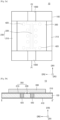
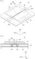
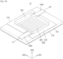
- FIG. 1 illustrates a high frequency switch 10 according to an embodiment.
- FIG. 2A is a plan view of FIG. 1 .
- FIG. 2B is a cross-sectional view taken along line I-I' of FIG. 1 .
- the high frequency switch 10 may include a substrate 100, a coplanar waveguide line 200, and a photoconductive semiconductor element 300.
- the substrate 100 may include a PCB.
- the coplanar waveguide line 200 may include a pair of ground sections 210 and a center conductor 220 between the pair of ground sections 210.
- the pair of ground sections 210 may extend in a first direction DR1 parallel to a top surface of the substrate 100, may face each other and be spaced apart from each other along a second direction DR2 that is parallel to the top surface of the substrate 100 and crosses the first direction DR1, and may include a conductive material, such as copper (Cu).
- a ground voltage may be applied to the pair of ground sections 210.
- the center conductor 220 may be provided between the pair of ground sections 210.
- the pair of ground sections 210 may be arranged from side to side on two side surfaces based on the center conductor 220, which may be linear, may extend along the first direction DR1, and may be spaced apart from the pair of ground sections 210 along the second direction DR2.
- the center conductor 220 may overlap the pair of ground sections 210 along the second direction DR2.
- a width of the center conductor 220 may be greater at both of its end portions than at its center portion, and may be a size of the center conductor 220 along the second direction DR2.
- the center conductor 220 may include a conductive material, such as Cu, and both end portions of the center conductor 220 may be electrically connected respectively to a pair of signal transmission lines 1000 described later, such as respectively directly contacting the pair of signal transmission lines.
- the photoconductive semiconductor element 300 may be provided on the coplanar waveguide line 200, may cover the center conductor 220 and the pair of ground sections 210, may extend between the center conductor 220 and the pair of ground sections 210, may fill regions between the center conductor 220 and the pair of ground sections 210, and may contact the substrate 100 between the center conductor 220 and the pair of ground sections 210.
- Conductivity of the photoconductive semiconductor element 300 may be adjusted by control light, and intrinsic electrical conductivity of the photoconductive semiconductor element 300 may be low.
- the photoconductive semiconductor element 300 may intrinsically have a dielectric state (an OFF state of the high frequency switch 10), in which the photoconductive semiconductor element 300 may electrically disconnect the center conductor 220 and the pair of ground sections 210 from each other.
- electrical conductivity of the photoconductive semiconductor element 300 may be increased.
- the photoconductive semiconductor element 300 may electrically connect the center conductor 220 and the pair of ground sections 210 to each other.
- the photoconductive semiconductor element 300 may include a semiconductor material having conductivity adjusted by the control light, such as silicon (Si), gallium-indium arsenide, or a combination thereof.
- a bottom ground layer 410 may be provided opposite to the coplanar waveguide line 200 with the substrate 100 therebetween.
- the bottom ground layer 410 may cover a bottom surface of the substrate 100.
- the bottom ground layer 410 may include a conductive material.
- the lower ground layer 410 may include a metal, such as Cu, and a ground voltage may be applied to the bottom ground layer 410.
- Vias 420 may be provided between the pair of ground sections 210 and the bottom ground layer 410 and may electrically connect the pair of ground sections 210 and the bottom ground layer 410 to each other.
- the vias 420 may directly contact the pair of ground sections 210 and the bottom ground layer 410, may penetrate the substrate 100, may extend along a third direction DR3 perpendicular to the top surface of the substrate 100, and may include a conductive material, such as Cu.
- the pair of signal transmission lines 1000 may be provided on the substrate 100, may be spaced apart from each other with the high frequency switch 10 therebetween, and may be respectively electrically connected to both end portions of the center conductor 220. For example, the pair of signal transmission lines 1000 may respectively directly contact the both end portions of the center conductor 220.
- a width of each of the pair of signal transmission lines 1000 may be materially identical to a width of each of the both end portions of the center conductor 220, and may be greater than a width of a center portion of the center conductor 220.
- One of the pair of signal transmission lines 1000 may be connected to a first port P1.
- the other one of the pair of signal transmission lines 1000 may be connected to a second port P2.
- the pair of signal transmission lines 1000 may include a conductive material, such as Cu.
- a size characteristic of the coplanar waveguide line 200 may be determined to provide wave impedance identical to an impedance of the pair of signal transmission lines 1000, such as 50 ⁇ .
- the size characteristic of the coplanar waveguide line 200 may include the width of the center conductor 220 and a distance between the center conductor 220 and the pair of ground sections 210.
- a dielectric constant of the photoconductive semiconductor element 300 may be considered while determining the size characteristic of the coplanar waveguide line 200.
- the pair of signal transmission lines 1000 and the high frequency switch 10 may be identical. As a result, when the high frequency switch 10 is in the OFF state, electromagnetic wave (signal) may propagate with minimal loss.
- the disclosure may provide the high frequency switch 10 using the photoconductive semiconductor element 300 having conductivity adjusted by control light.
- the high frequency switch 10 may include a minimal number of components. Accordingly, complexity, size, manufacturing costs, and power consumption of the high frequency switch 10 may be decreased.
- the high frequency switch 10 may be used in a wide frequency range (maximum 100 GHz) and may have low mmWave loss.
- the first and second ports P1 and P2 may be electrically disconnected from supply/bias circuits of the high frequency switch 10, which may have a high blocking performance.
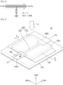
- FIG. 3 illustrates an OFF state of the high frequency switch 10 of FIGS. 1 , 2A and 2B .
- FIG. 4 is a cross-sectional view taken along line I-I' of FIG. 3 .
- FIG. 5 is an equivalent circuit of FIG. 3 .
- the high frequency switch 10 may be in the OFF state.
- the photoconductive semiconductor element 300 may be in the dielectric state.
- the center conductor 220 and the pair of ground sections 210 may be electrically disconnected from each other by the photoconductive semiconductor element 300.
- the pair of signal transmission lines 1000 and the high frequency switch 10 may impedance match each other. Accordingly, when the high frequency switch 10 is in the OFF state, electromagnetic (EM) waves may propagate through the high frequency switch 10 with minimal loss, and electric fields (EF) may be formed between the center conductor 220 and the pair of ground sections 210.
- EM electromagnetic
- EF electric fields
- the electromagnetic waves EM of FIG. 3 may propagate from the first port P1 to the second port P2 through the high frequency switch 10 of FIG. 3 .
- a transmission factor S12 between the first port P1 and the second port P2 may be 0 dB and may indicate loss of EM's when the EM's propagate from the first port P1 to the second port P2.
- the parallel resistance R may have a very large value. For example, the parallel resistance R may have a value close to infinity( ⁇ ).
- FIG. 6 illustrates an ON state of the high frequency switch 10 of FIGS. 1 , 2A and 2B .
- FIG. 7 is a cross-sectional view taken along line I-I' of FIG. 6 .
- FIG. 8 is an equivalent circuit of FIG. 6 .
- control light may be irradiated on the photoconductive semiconductor element 300 by being provided from the outside of the photoconductive semiconductor element 300. Accordingly, the photoconductive semiconductor element 300 may have a conductive state. The center conductor 220 and the pair of ground sections 210 may be electrically connected to each other by the photoconductive semiconductor element 300.
- a current may pass through the photoconductive semiconductor element 300 between the center conductor 220 and the pair of ground sections 210. Accordingly, a forward wave propagation condition of the high frequency switch 10 may be broken and a reverse wave propagation condition (i.e., a reflection condition) of the high frequency switch 10 may be created. As a result, the EM's may be reflected by the high frequency switch 10.
- Supply/bias circuits of the high frequency switch 10 may be separated from an RF wave path. The degree of reflection may be adjusted by control light power.
- Each of the photoconductive semiconductor elements 300 between the center conductor 220 and the pair of ground sections 210 may be identical to a parallel resistor for which resistance is calculated by Equation (1), as follows.
- Equation (1) R denotes resistance of a parallel resistor, ⁇ denotes conductivity of a photoconductive semiconductor element under control light, L denotes a length of a region through which a current passes (i.e., a width of a gap or distance between the center conductor 220 and the pair of ground sections 210), and S denotes a sectional area of a region through which a current passed along planar waveguide line.
- the current CR may flow from the center conductor 220 to the pair of ground sections 210 in the coplanar waveguide line 200.
- the sectional area S of the region through which the current CR passed along the coplanar waveguide line 200 may be a product of multiplying the length of the center conductor 220 and the thickness of the center conductor 220.
- the sectional area S of the region through which the current CR passed through along the coplanar waveguide line 200 may depend on the length of the center conductor 220.
- the equivalent circuit of the photoconductive semiconductor element 300 in the ON state is shown.
- the EM's propagated to the high frequency switch from the first port P1 may be reflected by the high frequency switch.
- the transmission factor S12 between the first port P1 and the second port P2 may be less than 0 dB.
- the parallel resistance R1 may have a value close to zero.
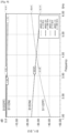
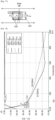
- FIG. 9 illustrates a simulation result regarding the ON state and the OFF state of the high frequency switch 10 of FIGS. 1 , 2A and 2B .
- transmission factors S12 and reflection factors S11 according to the ON state and the OFF state of the high frequency switch 10 described with reference to FIGS. 1 , 2A and 2B are shown.
- the transmission factors S12 indicate loss of the EM's when the high frequency switch 10 is in the OFF state.
- the reflection factors S11 indicate loss of the EM's when the high frequency switch 10 has the ON state.
- Dashed lines indicate the transmission factors S12 and solid lines indicate the reflection factors S11.
- the conductivity of the photoconductive semiconductor element 300 is 200 S/m, and a significant part of signal power is reflected.
- loss of a transmitted signal is over 31 dB and loss of a reflected signal is 1.74 dB.
- the conductivity of the photoconductive semiconductor element 300 is 0 S/m, and most of signal power is transmitted from the first port P1 to the second port P2.
- the loss of the transmitted signal is 0.1 dB and the loss of the reflected signal is 23 dB.
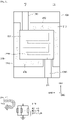
- FIG. 10 illustrates a high frequency switch 11 according to an embodiment.
- FIG. 11 is a plan view of FIG. 10 .
- FIG. 12 is an equivalent circuit of the high frequency switch 11 in an ON state. For conciseness, descriptions that are similar to those of FIGS. 1 , 2A and 2B are not repeated.
- the center conductor 220 may be non-linear, such as having a winding shape.
- a length of the non-linear center conductor 220 may be longer than the length of the linear center conductor 220.
- the pair of ground sections 210 may have a shape corresponding to the center conductor 220 such that the distances between the center conductor 220 and the pair of ground sections 210 are uniform.
- the regions between the center conductor 220 and the pair of ground sections 210 may be longer when the center conductor 220 is non-linear than when the center conductor 220 is linear. Accordingly, the photoconductive semiconductor element 300 provided between the center conductor 220 and the pair of ground sections 210 may also be longer when the center conductor 220 is non-linear than when the center conductor 220 is linear. When the lengths of the pair of ground sections 210 are increased, the combined resistance by the photoconductive semiconductor elements between the center conductor 220 and the pair of ground sections 210 may be decreased, thereby improving blocking performance of the high frequency switch 11.
- FIG. 12 illustrates the equivalent circuit of the high frequency switch in the ON state. Electromagnetic waves propagated from the first port P1 to the high frequency switch may be reflected by the high frequency switch.
- the transmission factor S12 between the first port P1 and the second port P2 may be less than 0 dB.
- a parallel resistance R2 may be the equivalent resistance of sub-parallel resistances R1 connected in parallel. The parallel resistance R2 may be smaller than the sub-parallel resistance R1.
- the parallel resistance R2 may have a value close to zero.
- FIG. 13 illustrates the simulation results of the operations of the high frequency switches 10 and 11.
- the center conductor 220 described with reference to FIGS. 10 and 11 may be longer than the center conductor 220 described with reference to FIGS. 1 , 2A and 2B (hereinafter, referred to as the linear center conductor 220).
- the non-linear center conductor 220 may have a winding shape that may extend in the first direction DR1.
- Dashed lines relate to the operation of the high frequency switch 11 including the non-linear center conductor 220 and solid lines relate to the operation of the high frequency switch 10 including the linear center conductor 220.
- the transmission factor S12 of the high frequency switch 11 in the ON state including the non-linear center conductor 220 is about -21 dB.
- the transmission factor S12 of the high frequency switch 10 in the ON state including the linear center conductor 220 is about -53 dB or more.
- the high frequency switch 11 in the ON state including the non-linear center conductor 220 has improved blocking performance than the high frequency switch 10 in the ON state including the linear center conductor 220.
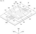
- FIG. 14 illustrates a high frequency switch 12 according to an embodiment.
- FIG. 15 is a plan view of FIG. 14 .
- FIG. 16 is an equivalent circuit of the high frequency switch 12 of FIG. 14 in an OFF state.
- FIG. 17 is an equivalent circuit of the high frequency switch 12 of FIG. 14 in an ON state.
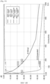
- FIG. 18 illustrates simulation results of operations of the high frequency switch 12 according to frequencies. For conciseness, descriptions that are similar to those of FIGS. 1 , 2A and 2B may not be repeated.
- the high frequency switch 12 further includes matching inductance elements 510 and capacitive stubs 520, which are connected to the center conductor 220 in parallel.
- the capacitive stubs 520 respectively extend from the matching inductance elements 510.
- the photoconductive semiconductor elements 300 may extend and fill regions between the center conductor 220, the pair of ground sections 210, and the capacitive stubs 520, and may contact the substrate 100 between the center conductor 220, the pair of ground sections 210, and the capacitive stubs 520.
- the matching inductance 510 and the capacitive stub 520 respectively have functions of an inductor and a capacitor with respect to a high frequency current, and are impedance-matched to each other and form a resonance structure.
- the matching inductance elements 510 and the capacitive stubs 520 do not affect propagation of electromagnetic waves in some frequency bands.
- the electromagnetic waves propagate with minimal loss.
- the equivalent circuit of the high frequency switch 12 in the ON state is shown.
- the photoconductive semiconductor element 300 When control light is irradiated on the photoconductive semiconductor element 300, the photoconductive semiconductor element 300 may become conductive.
- the center conductor 220 and the capacitive stubs 520 may be electrically connected to the pair of ground sections 210 by the photoconductive semiconductor element 300, and may have parallel resistance. Accordingly, combined resistance of the high frequency switch 12 may be decreased, thereby resulting in improved blocking performance of the high frequency switch 12.
- the transmission factors S12 and the reflection factors S11 with respect to a 3 GHz signal and a 6 GHz signal are provided.
- the transmission factor S12 with respect to the 3 GHz signal is shown in a thin solid line
- the transmission factor S12 with respect to the 6 GHz signal is shown in a thick solid line.
- the reflection factor S11 with respect to the 3 GHz signal is shown in a thin dashed line
- the reflection factor S11 with respect to the 6 GHz signal is shown in a thick dashed line.
- the transmission factor S12 with respect to the 6 GHz signal is about -37 dB
- the transmission factor S12 with respect to the 3 GHz signal is about -36 dB.
- the transmission factor S12 of the high frequency switch 12 described with reference to FIGS. 1 , 2A and 2B may be about -22 dB with respect to the 6 GHz signal when the conductivity of the photoconductive semiconductor element 300 is 100 S/m (see FIG. 13 ).
- the blocking performance of the high frequency switch 12 of this embodiment is greater than that of the high frequency switch 10 described with reference to FIGS. 1 , 2A and 2B .
- the reflection factor S11 of the high frequency switch 12 may be about -1 dB with respect to the 3 GHz and 6 GHz signals.
- the reflection factor S11 of the high frequency switch 10 described with reference to FIGS. 1 , 2A and 2B may be about -3 dB with respect to the 6 GHz signal when the conductivity of the photoconductive semiconductor element 300 is 100 S/m (see FIG. 13 ).
- the reflection loss of the high frequency switch 12 of this embodiment is less than that of the high frequency switch 10 described with reference to FIGS. 1 , 2A and 2B .
- FIG. 19 illustrates a high frequency switch 13 according to an embodiment. For conciseness, descriptions that are similar to those of FIGS. 1 , 2A and 2B may not be repeated.
- the high frequency switch 13 may include the substrate 100, a pair of ground electrodes 430, the bottom ground layer 410, a dielectric layer 600, the coplanar waveguide line 200, first top contacts 1200, second top contacts 1100, and the photoconductive semiconductor element 300.
- the substrate 100 and the bottom ground layer 410 may be similar to those described with reference to FIGS. 1 , 2A and 2B .
- the pair of ground electrodes 430 may be provided between the substrate 100 and the dielectric layer 600.
- the pair of ground electrodes 430 may be electrically connected to the bottom ground layer 410 by vias that may be similar to those described with reference to FIGS .1 , 2A and 2B .
- the dielectric layer 600 may be provided on the substrate 100, and although illustrated to cover a part of the substrate 100, the dielectric layer 600 may entirely cover the substrate 100 as an alternative.
- the coplanar waveguide line 200 may be provided on the dielectric layer 600 and may include the pair of ground sections 210 and the center conductor 220.
- the photoconductive semiconductor element 300 may be provided on the coplanar waveguide line 200.
- the coplanar waveguide line 200 and the photoconductive semiconductor element 300 may be similar to those described with reference to FIGS. 1 , 2A and 2B .
- the first top contacts 1200 may be provided between the pair of ground sections 210 and the pair of ground electrodes 430 and may electrically connect the pair of ground sections 210 and the pair of ground electrodes 430 to each other.
- the first top contacts 1200 may directly contact the pair of ground sections 210 and the pair of ground electrodes 430 and may include a conductive material, such as Cu.
- the pair of signal transmission lines 1000 may be provided on the substrate 100 between the substrate 100 and the dielectric layer 600, and may be similar to those described with reference to FIGS. 1 , 2A and 2B .
- the second top contacts 1100 may be provided between the pair of signal transmission lines 1000 and both end portions of the center conductor 220, and may electrically connect the pair of signal transmission lines 1000 and the both end portions of the center conductor 220 to each other.
- the second top contacts 1100 may directly contact the pair of signal transmission lines 1000 and the both end portions of the center conductor 220, and may include a conductive material, such as Cu.
- FIG. 20 is a cross-sectional view of a high frequency switch 14 according to an embodiment, which corresponds to line I-I' of FIG. 1 .
- FIGS. 1 , 2A and 2B For conciseness, descriptions that are similar to those of FIGS. 1 , 2A and 2B may not be repeated.
- the high frequency switch 14 including the substrate 100, the coplanar waveguide line 200, the photoconductive semiconductor element 300, the bottom ground layer 410, the vias 420, a light source 710, a controller 720, and a spacer 730 is provided.
- the substrate 100, the coplanar waveguide line 200, the photoconductive semiconductor element 300, the bottom ground layer 410, and the vias 420 may be similar to those described with reference to FIGS. 1 , 2A and 2B .
- the light source 710 may emit control light 7101 to the photoconductive semiconductor element 300.
- the light source 710 may include at least one of a light emitting diode (LED), a laser, or a laser diode.
- a working wavelength of the light source 710 i.e., a wavelength of the control light 7101
- the working wavelength of the light source 710 may be materially identical to a maximum absorption wavelength of the photoconductive semiconductor element 300.
- the photoconductive semiconductor element 300 includes Si
- the photoconductive semiconductor element 300 may have the maximum absorption wavelength at a near infrared ray (IR) range, such as about 940 nm.
- the light source 710 may be controlled by the controller 720.
- the controller 720 may control the light source 710 not to emit the control light 7101.
- the controller 720 may control the light source 710 to emit the control light 7101.
- the controller 720 may include a PCB on which a control circuit is mounted.
- the spacer 730 may uniformly maintain a distance between the photoconductive semiconductor element 300 and the light source 710 and may include a transparent dielectric material.
- FIG. 21 is a cross-sectional view of a high frequency switch 15 according to an embodiment, which corresponds to line I-I' of FIG. 1 .
- FIGS. 1 , 2A and 2B and 20 may not be repeated.
- the high frequency switch 15 may include the substrate 100, the coplanar waveguide line 200, the photoconductive semiconductor element 300, the bottom ground layer 410, the vias 420, a plurality of light sources 710, the controller 720, and the spacer 730.
- the substrate 100, the coplanar waveguide line 200, the photoconductive semiconductor element 300, the bottom ground layer 410, and the vias 420 may be similar to those described with reference to FIGS. 1 , 2A and 2B .
- the plurality of the light sources 710 may be provided in FIG. 21 .
- the control light 7101 emitted from the plurality of light sources 710 may be irradiated on a wider area of the photoconductive semiconductor element 300 than control light emitted from one light source. Accordingly, conductive distribution of the photoconductive semiconductor element 300 irradiated by the control light 7101 emitted from the plurality of light sources 710 may be more uniform than conductive distribution of the photoconductive semiconductor element 300 irradiated by the control light 7101 emitted from one light source 710.
- FIG. 22 is a plan view of a high frequency switch 16 according to an embodiment. For conciseness, descriptions that are similar to those described with reference to FIGS. 10 , 11 , and 20 may not be repeated.
- the high frequency switch 16 may include the substrate 100, the coplanar waveguide line 200, the photoconductive semiconductor element 300, and the pair of light sources 710.
- the substrate 100, the coplanar waveguide line 200, and the photoconductive semiconductor element 300 may be similar to those described with reference to FIGS. 10 and 11 .
- the pair of light sources 710 may be provided.
- the control light 7101 emitted from the pair of light sources 710 may be irradiated on a wider area of the photoconductive semiconductor element 300 than control light emitted from one light source. Accordingly, conductive distribution of the photoconductive semiconductor element 300 irradiated by the control light 7101 emitted from the pair of light sources 710 may be more uniform than conductive distribution of the photoconductive semiconductor element 300 irradiated by the control light 7101 emitted from one light source 710.
- FIG. 23 is a plan view of a high frequency switch 17 according to an embodiment. For conciseness, descriptions that are materially identical as those described with reference to FIGS. 10 , 11 , and 20 may not be repeated.
- the high frequency switch 17 may include the substrate 100, the coplanar waveguide line 200, the photoconductive semiconductor element 300, and a plurality of light sources 710.
- the substrate 100, the coplanar waveguide line 200, and the photoconductive semiconductor element 300 may be similar to those described with reference to FIGS. 10 and 11 .
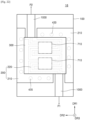
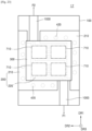
- the four light sources 710 may be provided.
- the control light 7101 emitted from the four light sources 710 may be irradiated on a wider area of the photoconductive semiconductor element 300 than control light emitted from one light source. Accordingly, conductive distribution of the photoconductive semiconductor element 300 irradiated by the control light 7101 emitted from the four light sources 710 may be more uniform than conductive distribution of the photoconductive semiconductor element 300 irradiated by the control light 7101 emitted from one light source 710.
- FIG. 24 is a cross-sectional view of a high frequency switch 18 according to an embodiment, which corresponds to line I-I' of FIG. 1 .
- FIGS. 1 , 2A and 2B and 20 may not be repeated.
- the high frequency switch 18 may include the substrate 100, the coplanar waveguide line 200, the photoconductive semiconductor element 300, the bottom ground layer 410, the vias 420, the light source 710, the controller 720, and the spacer 730.
- the substrate 100, the coplanar waveguide line 200, the photoconductive semiconductor element 300, the bottom ground layer 410, and the vias 420 may be similar to those described with reference to FIGS. 1 , 2A and 2B .
- the high frequency switch 18 may further include an optical fiber 740.
- the control light 7101 emitted from the light source 710 may reach the photoconductive semiconductor element 300 through the optical fiber 740.
- the high frequency switch 18 may include an optical waveguide instead of the optical fiber 740.
Landscapes
- Physics & Mathematics (AREA)
- Electromagnetism (AREA)
- Electronic Switches (AREA)
- Optical Modulation, Optical Deflection, Nonlinear Optics, Optical Demodulation, Optical Logic Elements (AREA)
- Waveguide Switches, Polarizers, And Phase Shifters (AREA)
- Switches Operated By Changes In Physical Conditions (AREA)
Description
- The disclosure relates generally to switches, and more particularly, to optically controlled switches for high-frequency signal transmitting/receiving devices with very high operating frequencies.
- A rapid growth in communication technologies is predicated upon the continuous evolution of user's needs. Currently, fifth generation partnership project (5G) millimeter wave (mmWave) networks are under development, which will exhibit higher performance in the user experience, including such factors as high transmission rate and power usage efficiency. 5G networks and car navigation sensors can change the scenario of wireless systems.
- New mmWave applications require the introduction of a new class of circuits that can integrate data transmission and detection abilities in a single wireless device. Among the available technologies, an important role is played by devices implemented on printed circuit boards (PCBs), as they are simple in design and manufacture, can be economically integrated into a single dielectric substrate, have a suitable base for broadband implementation, and are easily combined with traditional PCB technologies.
- Currently, PIN diodes, metal oxide semiconductor field effect transistor (MOSFET) devices, and micro-electromechanical systems (MEMS) are used as switching components in high frequency circuits. However, PIN diodes have a complex bias circuit (switching from positive current source to negative voltage), a MOSFET has high parasitic capacitance in low channel resistance, and a MEMS has a finite number of switching cycles and high control voltage.
- As such, the existing switching technologies for high-frequency signal transmitting/ receiving devices (keys, switches, phase shifters) are very sophisticated and therefore expensive, especially for frequencies over 10 GHz since they require miniaturization, cause radio frequency (RF) loss to be experienced due to intersection of RF channels with bias and DC supply circuits, are highly complex in terms of bias and supply circuits and occupy an excessive PCB area with bulky components, rendering integration into compact devices difficult.
- The above problems can be overcome by an optically controlled component with a bias circuit galvanically isolated from an RF channel. In this case, a "decoupled" RF channel is provided. Therefore, additional frequency filtering circuits, which are required with conventional components, can be omitted.
- Principle of operation of the optically controlled components is based on the photoconductivity effect, i.e. the ability of a semiconductor material to change its electrical characteristics by switching from a dielectric to conductive state depending on lighting. For example, a conventional photoconductive switch module provides a specific layer guiding light from light-emitting elements to photoconductive elements. However, the switching module has a bulky construction and consumes excessive power for lighting.
- Furthermore, a photoconductive switch includes a photoconductive material and first and second contacts provided on said photoconductive material, wherein said first and second contacts comprise a plurality of interdigitated tracks that are separated from the tracks of the other contact by a photoconductive gap and are curved such that the minimum photoconductive gap measured in a first direction remains substantially similar regardless of the orientation of the first direction. A disadvantage of the switch, however, is the parasitic capacitance causing additional wave leaking and lower isolation. In addition, the switch is not suitable for complete blocking of mmWaves.
- A microstrip diode high isolation switch is based on PIN diodes realizing a resultant obstacle into a broadband resonant circuit which may be switched between two states . When the diode is not conducting, the obstacle appears as an open circuit. However, in the Hallford switch the RF path circuits are disadvantageously coupled with bias and supply circuits of the PIN diodes, and the structure is rather bulky.
- A microstrip single pole double throw switch incorporating multiple MEMS contacts includes first pair of contacts is located adjacent to the junction of input and output lines for optimization of performance bandwidth. The MEMS contacts that are not located adjacent to the junction are spaced along the output lines to further optimize the bandwidth and isolation in the OFF state, while minimizing insertion loss in the ON state. However, the switch is a complicated arrangement of bias and supply circuits, and is expensive and difficult to manufacture for high frequency applications.
- Other microstrip radio frequency switches are based on a photoconductive switching element, which is series mounted in a microstrip line, such as in a stripline gap. In these switches, electric current is concentrated near semiconductor edges where electrical conductivity is low due to edge effects and respective surface recombination of carriers at the edges, while minimum current density is observed at the center of the microstrip where surface recombination is lower since it is technologically feasible to provide good surface quality of semiconductor material wafers from which these elements are made. As a consequence, high losses occur when electric current passes through the poorly conducting sections of the switch, and the switch requires a high optical power to switch to the ON state. In addition, the switch has a low blocking level due to parasitic capacitance.
"An Optically Controlled Co-Planar Waveguide Millimetre Wave Switch", Pang Alexander Weiran et al., discusses difficulties in implementing an optically controlled CPW switch at very high frequencies.
"Optimization of a Photonically Controlled Microwave Switch and Attenuator", Flemish J R et al., relates to a photoconductive switch and attenuator for microwave signals optimised for low insertion loss and high attenuation response upon illumination.
"Optical Control of Microstrip Stub on Silicon Substrate Using 650 nm and 850 nm Wavelengths Illumination", Avanish Bhadauria et al., demonstrates optical control of an RF signal through a microstrip-based stub structure having a length of λ/4. - Therefore, there is a need in the art to provide optically controlled switches for high-frequency signal transmitting/receiving devices with very high operating frequencies (up to about 100 GHz), which would simultaneously have low losses, low control power, a small size, and a simple supply/bias circuit to avoid spurious effects and low cost.
- An aspect of the disclosure is to address at least the above-mentioned problems and/or disadvantages and to provide at least the advantages described below. Accordingly, an aspect of the disclosure is to provide a high frequency switch having an improved blocking characteristic.
- Another aspect of the disclosure is to provide is a high frequency switch requiring low-power.
- According to an aspect of the present invention, there is provided a high frequency switch comprising the features of claim 1.
- The disclosure may provide the high frequency switch using the photoconductive semiconductor element having conductivity adjusted by control light.
- The above and other aspects, features, and advantages of certain embodiments of the disclosure will be more apparent from the following description taken in conjunction with the accompanying drawings, in which:
-
FIG. 1 illustrates a high frequency switch according to an embodiment; -
FIG. 2A is a plan view ofFIG. 1 ; -
FIG. 2B is a cross-sectional view taken along line I-I' ofFIG. 1 ; -
FIG. 3 illustrates an OFF state of the high frequency switch ofFIGS. 1 ,2A and 2B ; -
FIG. 4 is a cross-sectional view taken along line I-I' ofFIG. 3 ; -
FIG. 5 is an equivalent circuit ofFIG. 3 ; -
FIG. 6 illustrates an ON state of the high frequency switch ofFIGS. 1 ,2A and 2B ; -
FIG. 7 is a cross-sectional view taken along line I-I' ofFIG. 6 ; -
FIG. 8 is an equivalent circuit ofFIG. 6 ; -
FIG. 9 illustrates a simulation result of an operation of the high frequency switch ofFIGS. 1 ,2A and 2B ; -
FIG. 10 illustrates a high frequency switch according to an embodiment; -
FIG. 11 is a plan view ofFIG. 10 ; -
FIG. 12 is an equivalent circuit of a high frequency switch in an ON state; -
FIG. 13 illustrates the simulation result of the operation of the high frequency switch described with reference toFIGS. 1 ,2A and 2B and a simulation result of an operation of the high frequency switch described with reference toFIGS. 10 and11 ; -
FIG. 14 illustrates a high frequency switch according to an embodiment; -
FIG. 15 is a plan view ofFIG. 14 ; -
FIG. 16 is an equivalent circuit of the high frequency switch ofFIG. 14 in an OFF state; -
FIG. 17 is an equivalent circuit of the high frequency switch ofFIG. 14 in an ON state; -
FIG. 18 illustrates simulation results of operations of a high frequency switch according to frequencies; -
FIG. 19 illustrates a high frequency switch according to an embodiment; -
FIG. 20 is a cross-sectional view of a high frequency switch according to an embodiment, which corresponds to line I-I' ofFIG. 1 ; -
FIG. 21 is a cross-sectional view of a high frequency switch according to an embodiment, which corresponds to line I-I' ofFIG. 1 ; -
FIG. 22 is a plan view of a high frequency switch according to an embodiment; -
FIG. 23 is a plan view of a high frequency switch according to an embodiment; and -
FIG. 24 is a cross-sectional view of a high frequency switch which corresponds to line I-I' ofFIG. 1 , according to an embodiment. The embodiments associated withFIGs. 1-13 and17-24 are not encompassed by the wording of claim 1, but are considered useful for understanding the invention and illustrate the addition of optional features as defined in the dependent claims. - In accordance with an aspect of the disclosure, a high frequency switch includes a substrate, a pair of ground sections provided on the substrate, a center conductor provided between the pair of ground sections, and a photoconductive semiconductor element provided on the center conductor and extending between the center conductor and the pair of ground sections.
- In accordance with an aspect of the disclosure, a high frequency switch includes a pair of ground sections, a center conductor provided between the pair of ground sections, a photoconductive semiconductor element provided on the center conductor and extending between the center conductor and the pair of ground sections, and a light source irradiating control light on the photoconductive semiconductor element.
- In accordance with an aspect of the disclosure, a high frequency switch includes a substrate, a photoconductive semiconductor element provided on the substrate, and a coplanar waveguide line provided between the substrate and the photoconductive semiconductor element, wherein, when control light is irradiated on the photoconductive semiconductor element, electromagnetic waves propagated to the coplanar waveguide line are reflected, and wherein, when the control light is blocked from being irradiated on the photoconductive semiconductor element, the electromagnetic waves are passed through the high frequency switch.
- Hereinafter, embodiments of the disclosure will now be described with reference to accompanying drawings. In the drawings, like reference numerals refer to like elements, and a size of each component may be exaggerated for clarity and convenience. Embodiments of the disclosure described below are only examples and various modifications are possible. Detailed descriptions of known functions and configurations incorporated here will be omitted for the sake of clarity and conciseness.
- The term "above" or "on" may denote a component being directly on and in contact with another component or being on (over) yet not in contact with the another component.
- A singular expression includes a plural expression unless otherwise specified. When a part "includes" a component", the part may further include another component instead of excluding the other component, unless otherwise specified.
- In addition, the term "unit" used herein denotes a unit processing at least one function or operation, and may be implemented by hardware, software, or a combination of hardware and software.
- Throughout the disclosure, the expression "at least one of a, b or c" indicates only a, only b, only c, both a and b, both a and c, both b and c, all of a, b, and c, or variations thereof.
-
FIG. 1 illustrates ahigh frequency switch 10 according to an embodiment.FIG. 2A is a plan view ofFIG. 1 .FIG. 2B is a cross-sectional view taken along line I-I' ofFIG. 1 . - Referring to
FIGS. 1 ,2A and 2B , thehigh frequency switch 10 may include asubstrate 100, acoplanar waveguide line 200, and aphotoconductive semiconductor element 300. For example, thesubstrate 100 may include a PCB. - The
coplanar waveguide line 200 may include a pair ofground sections 210 and acenter conductor 220 between the pair ofground sections 210. The pair ofground sections 210 may extend in a first direction DR1 parallel to a top surface of thesubstrate 100, may face each other and be spaced apart from each other along a second direction DR2 that is parallel to the top surface of thesubstrate 100 and crosses the first direction DR1, and may include a conductive material, such as copper (Cu). A ground voltage may be applied to the pair ofground sections 210. - The
center conductor 220 may be provided between the pair ofground sections 210. For example, the pair ofground sections 210 may be arranged from side to side on two side surfaces based on thecenter conductor 220, which may be linear, may extend along the first direction DR1, and may be spaced apart from the pair ofground sections 210 along the second direction DR2. - Distances between the
center conductor 220 and the pair ofground sections 210 may be materially identical. Thecenter conductor 220 may overlap the pair ofground sections 210 along the second direction DR2. A width of thecenter conductor 220 may be greater at both of its end portions than at its center portion, and may be a size of thecenter conductor 220 along the second direction DR2. Thecenter conductor 220 may include a conductive material, such as Cu, and both end portions of thecenter conductor 220 may be electrically connected respectively to a pair ofsignal transmission lines 1000 described later, such as respectively directly contacting the pair of signal transmission lines. - The
photoconductive semiconductor element 300 may be provided on thecoplanar waveguide line 200, may cover thecenter conductor 220 and the pair ofground sections 210, may extend between thecenter conductor 220 and the pair ofground sections 210, may fill regions between thecenter conductor 220 and the pair ofground sections 210, and may contact thesubstrate 100 between thecenter conductor 220 and the pair ofground sections 210. - Conductivity of the
photoconductive semiconductor element 300 may be adjusted by control light, and intrinsic electrical conductivity of thephotoconductive semiconductor element 300 may be low. For example, thephotoconductive semiconductor element 300 may intrinsically have a dielectric state (an OFF state of the high frequency switch 10), in which thephotoconductive semiconductor element 300 may electrically disconnect thecenter conductor 220 and the pair ofground sections 210 from each other. When the control light is irradiated on thephotoconductive semiconductor element 300, electrical conductivity of thephotoconductive semiconductor element 300 may be increased. For example, when in a conductive state (an ON state of the high frequency switch 10), thephotoconductive semiconductor element 300 may electrically connect thecenter conductor 220 and the pair ofground sections 210 to each other. Thephotoconductive semiconductor element 300 may include a semiconductor material having conductivity adjusted by the control light, such as silicon (Si), gallium-indium arsenide, or a combination thereof. - A
bottom ground layer 410 may be provided opposite to thecoplanar waveguide line 200 with thesubstrate 100 therebetween. Thebottom ground layer 410 may cover a bottom surface of thesubstrate 100. Thebottom ground layer 410 may include a conductive material. For example, thelower ground layer 410 may include a metal, such as Cu, and a ground voltage may be applied to thebottom ground layer 410. -
Vias 420 may be provided between the pair ofground sections 210 and thebottom ground layer 410 and may electrically connect the pair ofground sections 210 and thebottom ground layer 410 to each other. For example, thevias 420 may directly contact the pair ofground sections 210 and thebottom ground layer 410, may penetrate thesubstrate 100, may extend along a third direction DR3 perpendicular to the top surface of thesubstrate 100, and may include a conductive material, such as Cu. - The pair of
signal transmission lines 1000 may be provided on thesubstrate 100, may be spaced apart from each other with thehigh frequency switch 10 therebetween, and may be respectively electrically connected to both end portions of thecenter conductor 220. For example, the pair ofsignal transmission lines 1000 may respectively directly contact the both end portions of thecenter conductor 220. A width of each of the pair ofsignal transmission lines 1000 may be materially identical to a width of each of the both end portions of thecenter conductor 220, and may be greater than a width of a center portion of thecenter conductor 220. One of the pair ofsignal transmission lines 1000 may be connected to a first port P1. The other one of the pair ofsignal transmission lines 1000 may be connected to a second port P2. The pair ofsignal transmission lines 1000 may include a conductive material, such as Cu. - A size characteristic of the
coplanar waveguide line 200 may be determined to provide wave impedance identical to an impedance of the pair ofsignal transmission lines 1000, such as 50 Ω. For example, the size characteristic of thecoplanar waveguide line 200 may include the width of thecenter conductor 220 and a distance between thecenter conductor 220 and the pair ofground sections 210. A dielectric constant of thephotoconductive semiconductor element 300 may be considered while determining the size characteristic of thecoplanar waveguide line 200. The pair ofsignal transmission lines 1000 and thehigh frequency switch 10 may be identical. As a result, when thehigh frequency switch 10 is in the OFF state, electromagnetic wave (signal) may propagate with minimal loss. - The disclosure may provide the
high frequency switch 10 using thephotoconductive semiconductor element 300 having conductivity adjusted by control light. Thehigh frequency switch 10 may include a minimal number of components. Accordingly, complexity, size, manufacturing costs, and power consumption of thehigh frequency switch 10 may be decreased. Thehigh frequency switch 10 may be used in a wide frequency range (maximum 100 GHz) and may have low mmWave loss. The first and second ports P1 and P2 may be electrically disconnected from supply/bias circuits of thehigh frequency switch 10, which may have a high blocking performance. -
FIG. 3 illustrates an OFF state of thehigh frequency switch 10 ofFIGS. 1 ,2A and2B .FIG. 4 is a cross-sectional view taken along line I-I' ofFIG. 3 .FIG. 5 is an equivalent circuit ofFIG. 3 . - Referring to
FIGS. 3 and 4 , thehigh frequency switch 10 may be in the OFF state. Thephotoconductive semiconductor element 300 may be in the dielectric state. Thecenter conductor 220 and the pair ofground sections 210 may be electrically disconnected from each other by thephotoconductive semiconductor element 300. The pair ofsignal transmission lines 1000 and thehigh frequency switch 10 may impedance match each other. Accordingly, when thehigh frequency switch 10 is in the OFF state, electromagnetic (EM) waves may propagate through thehigh frequency switch 10 with minimal loss, and electric fields (EF) may be formed between thecenter conductor 220 and the pair ofground sections 210. - Referring to
FIG. 5 , the electromagnetic waves EM ofFIG. 3 may propagate from the first port P1 to the second port P2 through thehigh frequency switch 10 ofFIG. 3 . A transmission factor S12 between the first port P1 and the second port P2 may be 0 dB and may indicate loss of EM's when the EM's propagate from the first port P1 to the second port P2. The parallel resistance R may have a very large value. For example, the parallel resistance R may have a value close to infinity(∞). -
FIG. 6 illustrates an ON state of thehigh frequency switch 10 ofFIGS. 1 ,2A and2B .FIG. 7 is a cross-sectional view taken along line I-I' ofFIG. 6 .FIG. 8 is an equivalent circuit ofFIG. 6 . - Referring to
FIGS. 6 and7 , control light (LL) may be irradiated on thephotoconductive semiconductor element 300 by being provided from the outside of thephotoconductive semiconductor element 300. Accordingly, thephotoconductive semiconductor element 300 may have a conductive state. Thecenter conductor 220 and the pair ofground sections 210 may be electrically connected to each other by thephotoconductive semiconductor element 300. When the EM's propagate from the first port P1 to thehigh frequency switch 10, a current (CR) may pass through thephotoconductive semiconductor element 300 between thecenter conductor 220 and the pair ofground sections 210. Accordingly, a forward wave propagation condition of thehigh frequency switch 10 may be broken and a reverse wave propagation condition (i.e., a reflection condition) of thehigh frequency switch 10 may be created. As a result, the EM's may be reflected by thehigh frequency switch 10. Supply/bias circuits of thehigh frequency switch 10 may be separated from an RF wave path. The degree of reflection may be adjusted by control light power. - Each of the
photoconductive semiconductor elements 300 between thecenter conductor 220 and the pair ofground sections 210 may be identical to a parallel resistor for which resistance is calculated by Equation (1), as follows.

- In Equation (1), R denotes resistance of a parallel resistor, σ denotes conductivity of a photoconductive semiconductor element under control light, L denotes a length of a region through which a current passes (i.e., a width of a gap or distance between the
center conductor 220 and the pair of ground sections 210), and S denotes a sectional area of a region through which a current passed along planar waveguide line. - The current CR may flow from the
center conductor 220 to the pair ofground sections 210 in thecoplanar waveguide line 200. The sectional area S of the region through which the current CR passed along thecoplanar waveguide line 200 may be a product of multiplying the length of thecenter conductor 220 and the thickness of thecenter conductor 220. The sectional area S of the region through which the current CR passed through along thecoplanar waveguide line 200 may depend on the length of thecenter conductor 220. When combined resistance by thephotoconductive semiconductor elements 300 between thecenter conductor 220 and the pair ofground sections 210 is minimal, blocking performance of thehigh frequency switch 10 may be high, and therefore, may be defined by the length of thecenter conductor 220. - Referring to
FIG. 8 , the equivalent circuit of thephotoconductive semiconductor element 300 in the ON state is shown. The EM's propagated to the high frequency switch from the first port P1 may be reflected by the high frequency switch. The transmission factor S12 between the first port P1 and the second port P2 may be less than 0 dB. The parallel resistance R1 may have a value close to zero. -
FIG. 9 illustrates a simulation result regarding the ON state and the OFF state of thehigh frequency switch 10 ofFIGS. 1 ,2A and 2B . - Referring to
FIG. 9 , transmission factors S12 and reflection factors S11 according to the ON state and the OFF state of thehigh frequency switch 10 described with reference toFIGS. 1 ,2A and 2B are shown. The transmission factors S12 indicate loss of the EM's when thehigh frequency switch 10 is in the OFF state. The reflection factors S11 indicate loss of the EM's when thehigh frequency switch 10 has the ON state. Dashed lines indicate the transmission factors S12 and solid lines indicate the reflection factors S11. - When the
high frequency switch 10 is in the ON state (i.e., when control light is irradiated on the photoconductive semiconductor element 300), the conductivity of thephotoconductive semiconductor element 300 is 200 S/m, and a significant part of signal power is reflected. At a signal frequency of 6 GHz, loss of a transmitted signal is over 31 dB and loss of a reflected signal is 1.74 dB. - When the
high frequency switch 10 is in the OFF state (i.e., when there is no control light), the conductivity of thephotoconductive semiconductor element 300 is 0 S/m, and most of signal power is transmitted from the first port P1 to the second port P2. At the signal frequency of 6 GHz, the loss of the transmitted signal is 0.1 dB and the loss of the reflected signal is 23 dB. -
FIG. 10 illustrates ahigh frequency switch 11 according to an embodiment.FIG. 11 is a plan view ofFIG. 10 .FIG. 12 is an equivalent circuit of thehigh frequency switch 11 in an ON state. For conciseness, descriptions that are similar to those ofFIGS. 1 ,2A and 2B are not repeated. - Unlike in
FIGS. 1 and2A , referring toFIGS. 10 and11 , thecenter conductor 220 may be non-linear, such as having a winding shape. A length of thenon-linear center conductor 220 may be longer than the length of thelinear center conductor 220. - The pair of
ground sections 210 may have a shape corresponding to thecenter conductor 220 such that the distances between thecenter conductor 220 and the pair ofground sections 210 are uniform. - The regions between the
center conductor 220 and the pair ofground sections 210 may be longer when thecenter conductor 220 is non-linear than when thecenter conductor 220 is linear. Accordingly, thephotoconductive semiconductor element 300 provided between thecenter conductor 220 and the pair ofground sections 210 may also be longer when thecenter conductor 220 is non-linear than when thecenter conductor 220 is linear. When the lengths of the pair ofground sections 210 are increased, the combined resistance by the photoconductive semiconductor elements between thecenter conductor 220 and the pair ofground sections 210 may be decreased, thereby improving blocking performance of thehigh frequency switch 11. -
FIG. 12 illustrates the equivalent circuit of the high frequency switch in the ON state. Electromagnetic waves propagated from the first port P1 to the high frequency switch may be reflected by the high frequency switch. The transmission factor S12 between the first port P1 and the second port P2 may be less than 0 dB. A parallel resistance R2 may be the equivalent resistance of sub-parallel resistances R1 connected in parallel. The parallel resistance R2 may be smaller than the sub-parallel resistance R1. The parallel resistance R2 may have a value close to zero. -
FIG. 13 illustrates the simulation results of the operations of the high frequency switches 10 and 11. - Referring to
FIG. 13 , the comparison graph of the transmission factors S12 and the reflection factors S11 of thehigh frequency switch 10 described with reference toFIGS. 1 ,2A and 2B and thehigh frequency switch 11 described with reference toFIGS. 10 and11 is shown. Thecenter conductor 220 described with reference toFIGS. 10 and11 (hereinafter, referred to as the non-linear center conductor 220) may be longer than thecenter conductor 220 described with reference toFIGS. 1 ,2A and 2B (hereinafter, referred to as the linear center conductor 220). For example, thenon-linear center conductor 220 may have a winding shape that may extend in the first direction DR1. - Dashed lines relate to the operation of the
high frequency switch 11 including thenon-linear center conductor 220 and solid lines relate to the operation of thehigh frequency switch 10 including thelinear center conductor 220. When the signal frequency is 6 GHz and the conductivity of thephotoconductive semiconductor element 300 is 100 S/m, the transmission factor S12 of thehigh frequency switch 11 in the ON state including thenon-linear center conductor 220 is about -21 dB. When the signal frequency is 6 GHz and thephotoconductive semiconductor element 300 is 100 S/m, the transmission factor S12 of thehigh frequency switch 10 in the ON state including thelinear center conductor 220 is about -53 dB or more. Thehigh frequency switch 11 in the ON state including thenon-linear center conductor 220 has improved blocking performance than thehigh frequency switch 10 in the ON state including thelinear center conductor 220. -
FIG. 14 illustrates ahigh frequency switch 12 according to an embodiment.FIG. 15 is a plan view ofFIG. 14 .FIG. 16 is an equivalent circuit of thehigh frequency switch 12 ofFIG. 14 in an OFF state.FIG. 17 is an equivalent circuit of thehigh frequency switch 12 ofFIG. 14 in an ON state.FIG. 18 illustrates simulation results of operations of thehigh frequency switch 12 according to frequencies. For conciseness, descriptions that are similar to those ofFIGS. 1 ,2A and 2B may not be repeated. - Unlike
FIGS. 1 ,2A and 2B , referring toFIGS. 14 and15 , thehigh frequency switch 12 further includes matchinginductance elements 510 andcapacitive stubs 520, which are connected to thecenter conductor 220 in parallel. Thecapacitive stubs 520 respectively extend from the matchinginductance elements 510. - The
photoconductive semiconductor elements 300 may extend and fill regions between thecenter conductor 220, the pair ofground sections 210, and thecapacitive stubs 520, and may contact thesubstrate 100 between thecenter conductor 220, the pair ofground sections 210, and thecapacitive stubs 520. - Referring to
FIG. 16 , the equivalent circuit of thehigh frequency switch 12 in the OFF state is shown. The matchinginductance 510 and thecapacitive stub 520 respectively have functions of an inductor and a capacitor with respect to a high frequency current, and are impedance-matched to each other and form a resonance structure. The matchinginductance elements 510 and thecapacitive stubs 520 do not affect propagation of electromagnetic waves in some frequency bands. When thehigh frequency switch 12 is in the OFF state, the electromagnetic waves propagate with minimal loss. - Referring to
FIG. 17 , the equivalent circuit of thehigh frequency switch 12 in the ON state is shown. When control light is irradiated on thephotoconductive semiconductor element 300, thephotoconductive semiconductor element 300 may become conductive. Thecenter conductor 220 and thecapacitive stubs 520 may be electrically connected to the pair ofground sections 210 by thephotoconductive semiconductor element 300, and may have parallel resistance. Accordingly, combined resistance of thehigh frequency switch 12 may be decreased, thereby resulting in improved blocking performance of thehigh frequency switch 12. - Referring to
FIG. 18 , the transmission factors S12 and the reflection factors S11 with respect to a 3 GHz signal and a 6 GHz signal are provided. The transmission factor S12 with respect to the 3 GHz signal is shown in a thin solid line, and the transmission factor S12 with respect to the 6 GHz signal is shown in a thick solid line. The reflection factor S11 with respect to the 3 GHz signal is shown in a thin dashed line, and the reflection factor S11 with respect to the 6 GHz signal is shown in a thick dashed line. When the conductivity of thephotoconductive semiconductor element 300 is 100 S/m, the transmission factor S12 with respect to the 6 GHz signal is about -37 dB, and the transmission factor S12 with respect to the 3 GHz signal is about -36 dB. The transmission factor S12 of thehigh frequency switch 12 described with reference toFIGS. 1 ,2A and 2B may be about -22 dB with respect to the 6 GHz signal when the conductivity of thephotoconductive semiconductor element 300 is 100 S/m (seeFIG. 13 ). The blocking performance of thehigh frequency switch 12 of this embodiment is greater than that of thehigh frequency switch 10 described with reference toFIGS. 1 ,2A and 2B . - When the conductivity of the
photoconductive semiconductor element 300 is 100 S/ m, the reflection factor S11 of thehigh frequency switch 12 may be about -1 dB with respect to the 3 GHz and 6 GHz signals. The reflection factor S11 of thehigh frequency switch 10 described with reference toFIGS. 1 ,2A and 2B may be about -3 dB with respect to the 6 GHz signal when the conductivity of thephotoconductive semiconductor element 300 is 100 S/m (seeFIG. 13 ). The reflection loss of thehigh frequency switch 12 of this embodiment is less than that of thehigh frequency switch 10 described with reference toFIGS. 1 ,2A and 2B . -
FIG. 19 illustrates ahigh frequency switch 13 according to an embodiment. For conciseness, descriptions that are similar to those ofFIGS. 1 ,2A and 2B may not be repeated. - Referring to
FIG. 19 , thehigh frequency switch 13 may include thesubstrate 100, a pair ofground electrodes 430, thebottom ground layer 410, adielectric layer 600, thecoplanar waveguide line 200, firsttop contacts 1200, secondtop contacts 1100, and thephotoconductive semiconductor element 300. Thesubstrate 100 and thebottom ground layer 410 may be similar to those described with reference toFIGS. 1 ,2A and 2B . The pair ofground electrodes 430 may be provided between thesubstrate 100 and thedielectric layer 600. The pair ofground electrodes 430 may be electrically connected to thebottom ground layer 410 by vias that may be similar to those described with reference toFIGS .1 ,2A and 2B . - The
dielectric layer 600 may be provided on thesubstrate 100, and although illustrated to cover a part of thesubstrate 100, thedielectric layer 600 may entirely cover thesubstrate 100 as an alternative. - The
coplanar waveguide line 200 may be provided on thedielectric layer 600 and may include the pair ofground sections 210 and thecenter conductor 220. Thephotoconductive semiconductor element 300 may be provided on thecoplanar waveguide line 200. Thecoplanar waveguide line 200 and thephotoconductive semiconductor element 300 may be similar to those described with reference toFIGS. 1 ,2A and 2B . - The first
top contacts 1200 may be provided between the pair ofground sections 210 and the pair ofground electrodes 430 and may electrically connect the pair ofground sections 210 and the pair ofground electrodes 430 to each other. For example, the firsttop contacts 1200 may directly contact the pair ofground sections 210 and the pair ofground electrodes 430 and may include a conductive material, such as Cu. - The pair of
signal transmission lines 1000 may be provided on thesubstrate 100 between thesubstrate 100 and thedielectric layer 600, and may be similar to those described with reference toFIGS. 1 ,2A and 2B . - The second
top contacts 1100 may be provided between the pair ofsignal transmission lines 1000 and both end portions of thecenter conductor 220, and may electrically connect the pair ofsignal transmission lines 1000 and the both end portions of thecenter conductor 220 to each other. For example, the secondtop contacts 1100 may directly contact the pair ofsignal transmission lines 1000 and the both end portions of thecenter conductor 220, and may include a conductive material, such as Cu. -
FIG. 20 is a cross-sectional view of ahigh frequency switch 14 according to an embodiment, which corresponds to line I-I' ofFIG. 1 . For conciseness, descriptions that are similar to those ofFIGS. 1 ,2A and 2B may not be repeated. - Referring to
FIG. 20 , thehigh frequency switch 14 including thesubstrate 100, thecoplanar waveguide line 200, thephotoconductive semiconductor element 300, thebottom ground layer 410, thevias 420, alight source 710, acontroller 720, and aspacer 730 is provided. Thesubstrate 100, thecoplanar waveguide line 200, thephotoconductive semiconductor element 300, thebottom ground layer 410, and thevias 420 may be similar to those described with reference toFIGS. 1 ,2A and 2B . - The
light source 710 may emit control light 7101 to thephotoconductive semiconductor element 300. For example, thelight source 710 may include at least one of a light emitting diode (LED), a laser, or a laser diode. A working wavelength of the light source 710 (i.e., a wavelength of the control light 7101) may be selected based on absorption capability of thephotoconductive semiconductor element 300. For example, the working wavelength of thelight source 710 may be materially identical to a maximum absorption wavelength of thephotoconductive semiconductor element 300. When thephotoconductive semiconductor element 300 includes Si, thephotoconductive semiconductor element 300 may have the maximum absorption wavelength at a near infrared ray (IR) range, such as about 940 nm. Thelight source 710 may be controlled by thecontroller 720. When thehigh frequency switch 14 is in the OFF state, thecontroller 720 may control thelight source 710 not to emit the control light 7101. When thehigh frequency switch 14 is in the ON state, thecontroller 720 may control thelight source 710 to emit the control light 7101. Thecontroller 720 may include a PCB on which a control circuit is mounted. - The
spacer 730 may uniformly maintain a distance between thephotoconductive semiconductor element 300 and thelight source 710 and may include a transparent dielectric material. -
FIG. 21 is a cross-sectional view of ahigh frequency switch 15 according to an embodiment, which corresponds to line I-I' ofFIG. 1 . For conciseness, descriptions that are similar to those described with reference toFIGS. 1 ,2A and 2B and20 may not be repeated. - Referring to
FIG. 21 , thehigh frequency switch 15 may include thesubstrate 100, thecoplanar waveguide line 200, thephotoconductive semiconductor element 300, thebottom ground layer 410, thevias 420, a plurality oflight sources 710, thecontroller 720, and thespacer 730. Thesubstrate 100, thecoplanar waveguide line 200, thephotoconductive semiconductor element 300, thebottom ground layer 410, and thevias 420 may be similar to those described with reference toFIGS. 1 ,2A and 2B . - Unlike
FIG. 20 , the plurality of thelight sources 710 may be provided inFIG. 21 . The control light 7101 emitted from the plurality oflight sources 710 may be irradiated on a wider area of thephotoconductive semiconductor element 300 than control light emitted from one light source. Accordingly, conductive distribution of thephotoconductive semiconductor element 300 irradiated by the control light 7101 emitted from the plurality oflight sources 710 may be more uniform than conductive distribution of thephotoconductive semiconductor element 300 irradiated by the control light 7101 emitted from onelight source 710. -
FIG. 22 is a plan view of ahigh frequency switch 16 according to an embodiment. For conciseness, descriptions that are similar to those described with reference toFIGS. 10 ,11 , and20 may not be repeated. - Referring to
FIG. 22 , thehigh frequency switch 16 may include thesubstrate 100, thecoplanar waveguide line 200, thephotoconductive semiconductor element 300, and the pair oflight sources 710. Thesubstrate 100, thecoplanar waveguide line 200, and thephotoconductive semiconductor element 300 may be similar to those described with reference toFIGS. 10 and11 . - Unlike
FIG. 20 , the pair oflight sources 710 may be provided. The control light 7101 emitted from the pair oflight sources 710 may be irradiated on a wider area of thephotoconductive semiconductor element 300 than control light emitted from one light source. Accordingly, conductive distribution of thephotoconductive semiconductor element 300 irradiated by the control light 7101 emitted from the pair oflight sources 710 may be more uniform than conductive distribution of thephotoconductive semiconductor element 300 irradiated by the control light 7101 emitted from onelight source 710. -
FIG. 23 is a plan view of ahigh frequency switch 17 according to an embodiment. For conciseness, descriptions that are materially identical as those described with reference toFIGS. 10 ,11 , and20 may not be repeated. - Referring to
FIG. 23 , thehigh frequency switch 17 may include thesubstrate 100, thecoplanar waveguide line 200, thephotoconductive semiconductor element 300, and a plurality oflight sources 710. Thesubstrate 100, thecoplanar waveguide line 200, and thephotoconductive semiconductor element 300 may be similar to those described with reference toFIGS. 10 and11 . - Unlike
FIG. 20 , the fourlight sources 710 may be provided. The control light 7101 emitted from the fourlight sources 710 may be irradiated on a wider area of thephotoconductive semiconductor element 300 than control light emitted from one light source. Accordingly, conductive distribution of thephotoconductive semiconductor element 300 irradiated by the control light 7101 emitted from the fourlight sources 710 may be more uniform than conductive distribution of thephotoconductive semiconductor element 300 irradiated by the control light 7101 emitted from onelight source 710. -
FIG. 24 is a cross-sectional view of ahigh frequency switch 18 according to an embodiment, which corresponds to line I-I' ofFIG. 1 . For conciseness, descriptions that are similar to those described with reference toFIGS. 1 ,2A and 2B and20 may not be repeated. - Referring to
FIG. 24 , thehigh frequency switch 18 may include thesubstrate 100, thecoplanar waveguide line 200, thephotoconductive semiconductor element 300, thebottom ground layer 410, thevias 420, thelight source 710, thecontroller 720, and thespacer 730. Thesubstrate 100, thecoplanar waveguide line 200, thephotoconductive semiconductor element 300, thebottom ground layer 410, and thevias 420 may be similar to those described with reference toFIGS. 1 ,2A and 2B . - Unlike
FIG. 20 , referring toFIG. 24 , thehigh frequency switch 18 may further include anoptical fiber 740. The control light 7101 emitted from thelight source 710 may reach thephotoconductive semiconductor element 300 through theoptical fiber 740. According to an embodiment, thehigh frequency switch 18 may include an optical waveguide instead of theoptical fiber 740. - While the present disclosure has been shown and described with reference to certain embodiments thereof, it will be understood by those skilled in the art that various changes in form and details may be made therein without departing from the scope of the disclosure as defined by the appended claims.
Claims (13)
- A high frequency switch (10) comprising:a substrate (100);a pair of ground sections (210) provided on the substrate;a center conductor (220) provided between the pair of ground sections;a photoconductive semiconductor element (300) provided on the center conductor and extending between the center conductor and the pair of ground sections;characterized in that the high frequency switch further comprises a plurality of capacitive stubs (520); anda plurality of matching inductance elements (510),
wherein the plurality of capacitive stubs and the plurality of matching inductance elements are impedance-matched to each other. - The high frequency switch of claim 1, wherein the photoconductive semiconductor element (300) fills regions between the center conductor (220) and the pair of ground sections (210).
- The high frequency switch (10) of claim 1 or 2, wherein the center conductor (220) has a line shape extending in one direction parallel to a top surface of the substrate (100).
- The high frequency switch (10) of any one of claims 1 to 3, further comprising:a bottom ground layer (410) covering a bottom surface of the substrate (100); anda plurality of vias (420) electrically connecting the bottom ground layer and the pair of ground sections (210) to each other, wherein the plurality of vias penetrate the substrate.
- The high frequency switch (10) of any one of claims 1 to 4, wherein the center conductor (220) extends non-linearly.
- The high frequency switch (10) of any one of claims 1 to 5, further comprising a pair of signal transmission lines (1000) provided on the substrate (100),wherein the pair of signal transmission lines are respectively electrically connected to both end portions of the center conductor (220), andwherein a width of each of the pair of signal transmission lines is greater than a width of the center conductor.
- The high frequency switch (10) of claim 1, further comprising a light source (710) configured to irradiate control light (710l) on the photoconductive semiconductor element (300).
- The high frequency switch (10) of claim 7, wherein the light source (710) is provided on the photoconductive semiconductor element (300).
- The high frequency switch (10) of claim 7 or 8, wherein the light source (710) comprises a plurality of light sources.
- The high frequency switch (10) of any one of claims 7 to 9, further comprising an optical fiber (740) provided between the light source (710) and the photoconductive semiconductor element (300), wherein the optical fiber is configured to transmit the control light (710l) to the photoconductive semiconductor element.
- The high frequency switch (10) of claim 1,wherein the pair of ground sections (210) and the center conductor (220) comprise a coplanar waveguide line (200) provided between the substrate (100) and the photoconductive semiconductor element (300),wherein the high frequency switch is configured to reflect electromagnetic waves propagated to the coplanar waveguide line in response to control light (710l) being irradiated on the photoconductive semiconductor element, andwherein the high frequency switch is configured to allow transmission of the electromagnetic waves through the high frequency switch in response to the control light being blocked from being irradiated on the photoconductive semiconductor element.
- The high frequency switch (10) of claim 11, further comprising a light source (710) configured to irradiate the control light (710l) on the photoconductive semiconductor element (300).
- The high frequency switch (10) of claim 12, wherein the light source (710) is configured to emit the control light (710l) having a wavelength band comprising a maximum absorption wavelength of the photoconductive semiconductor element (300).
Applications Claiming Priority (3)
| Application Number | Priority Date | Filing Date | Title |
|---|---|---|---|
| RU2018123298A RU2685768C9 (en) | 2018-06-27 | 2018-06-27 | Millimeter optically controlling range |
| KR1020190033201A KR102710802B1 (en) | 2018-06-27 | 2019-03-22 | Radio frequency switch |
| PCT/KR2019/007838 WO2020004991A1 (en) | 2018-06-27 | 2019-06-27 | High frequency switch for high frequency signal transmitting/receiving devices |
Publications (3)
| Publication Number | Publication Date |
|---|---|
| EP3807937A1 EP3807937A1 (en) | 2021-04-21 |
| EP3807937A4 EP3807937A4 (en) | 2021-08-11 |
| EP3807937B1 true EP3807937B1 (en) | 2023-03-29 |
Family
ID=66314731
Family Applications (1)
| Application Number | Title | Priority Date | Filing Date |
|---|---|---|---|
| EP19826407.9A Active EP3807937B1 (en) | 2018-06-27 | 2019-06-27 | High frequency switch for high frequency signal transmitting/receiving devices |
Country Status (3)
| Country | Link |
|---|---|
| EP (1) | EP3807937B1 (en) |
| KR (1) | KR102710802B1 (en) |
| RU (1) | RU2685768C9 (en) |
Cited By (1)
| Publication number | Priority date | Publication date | Assignee | Title |
|---|---|---|---|---|
| WO2025215343A1 (en) * | 2024-04-09 | 2025-10-16 | The University Of Bristol | Radio frequency device |
Families Citing this family (3)
| Publication number | Priority date | Publication date | Assignee | Title |
|---|---|---|---|---|
| WO2021112568A1 (en) | 2019-12-03 | 2021-06-10 | 삼성전자 주식회사 | Optical control switch and electronic device comprising same |
| RU2721303C1 (en) * | 2019-12-03 | 2020-05-18 | Самсунг Электроникс Ко., Лтд. | Optically-controlled switch of millimeter range with built-in light source, based on transmission line with semiconductor substrate |
| KR102535309B1 (en) * | 2022-11-22 | 2023-05-26 | 국방과학연구소 | Photoconductive semiconductor switch for inducing dispersion of conducting filament |
Family Cites Families (6)
| Publication number | Priority date | Publication date | Assignee | Title |
|---|---|---|---|---|
| US7570137B2 (en) * | 2005-11-14 | 2009-08-04 | Northrop Grumman Corporation | Monolithic microwave integrated circuit (MMIC) waveguide resonators having a tunable ferroelectric layer |
| GB2493193B (en) * | 2011-07-27 | 2015-07-08 | Thales Holdings Uk Plc | Semiconductor device for optoelectric switching |
| RU2503087C1 (en) * | 2012-06-15 | 2013-12-27 | Открытое акционерное общество "Научно-исследовательский институт полупроводниковых приборов" (ОАО "НИИПП") | Millimetre-range monolithic integrated circuit |
| RU148921U1 (en) * | 2014-06-10 | 2014-12-20 | Федеральное государственное бюджетное образовательное учреждение высшего профессионального образования "Новгородский государственный университет имени Ярослава Мудрого" | COMPLETE FAN ATTENUATOR |
| RU2600506C1 (en) * | 2015-10-02 | 2016-10-20 | Общество с ограниченной ответственностью "Радио Гигабит" | Waveguide-microstrip junction |
| US9758366B2 (en) * | 2015-12-15 | 2017-09-12 | International Business Machines Corporation | Small wafer area MEMS switch |
-
2018
- 2018-06-27 RU RU2018123298A patent/RU2685768C9/en active
-
2019
- 2019-03-22 KR KR1020190033201A patent/KR102710802B1/en active Active
- 2019-06-27 EP EP19826407.9A patent/EP3807937B1/en active Active
Cited By (1)
| Publication number | Priority date | Publication date | Assignee | Title |
|---|---|---|---|---|
| WO2025215343A1 (en) * | 2024-04-09 | 2025-10-16 | The University Of Bristol | Radio frequency device |
Also Published As
| Publication number | Publication date |
|---|---|
| KR102710802B1 (en) | 2024-09-26 |
| EP3807937A1 (en) | 2021-04-21 |
| EP3807937A4 (en) | 2021-08-11 |
| RU2685768C9 (en) | 2019-08-01 |
| KR20200001457A (en) | 2020-01-06 |
| RU2685768C1 (en) | 2019-04-23 |
Similar Documents
| Publication | Publication Date | Title |
|---|---|---|
| US10802375B2 (en) | Optically-controlled switch | |
| US7561006B2 (en) | Low loss electrical delay line | |
| CN112166526B (en) | Method for controlling transmission of electromagnetic wave based on light and apparatus therefor | |
| US9985331B2 (en) | Substrate integrated waveguide switch | |
| KR102615092B1 (en) | Optically-controlled switch | |
| KR102710802B1 (en) | Radio frequency switch | |
| JP2004088715A (en) | High frequency switch and electronic device using the same | |
| KR102650548B1 (en) | Single-pole multi-throw switching device with simple structure | |
| CN112164866B (en) | High-isolation reconfigurable slot antenna based on S-PIN solid-state plasma and frequency reconfiguration method thereof | |
| US11233507B2 (en) | High frequency switch for high frequency signal transmitting/receiving devices | |
| JP5217947B2 (en) | High frequency functional element structure and high frequency functional component | |
| US20220199849A1 (en) | Optical control switch and electronic device comprising same | |
| CN209786154U (en) | plasma waveguide phase shifter | |
| JPH0563409A (en) | Waveguide | |
| JP4547992B2 (en) | High frequency switch and electronic device using the same | |
| US11069949B2 (en) | Hollow-waveguide-to-planar-waveguide transition circuit comprising a coupling conductor disposed over slots in a ground conductor | |
| KR102898490B1 (en) | Optically controlled switch and electronic device including the same | |
| US6998933B1 (en) | Millimeter wave switch | |
| KR20180089268A (en) | High-frequency device based on liquid crystals and high frequency switch with the same | |
| KR101419184B1 (en) | Substrate integrated waveguide switch | |
| CN117525788A (en) | A characteristic impedance reconfigurable transmission line and characteristic impedance switching method |
Legal Events
| Date | Code | Title | Description |
|---|---|---|---|
| STAA | Information on the status of an ep patent application or granted ep patent |
Free format text: STATUS: THE INTERNATIONAL PUBLICATION HAS BEEN MADE |
|
| PUAI | Public reference made under article 153(3) epc to a published international application that has entered the european phase |
Free format text: ORIGINAL CODE: 0009012 |
|
| STAA | Information on the status of an ep patent application or granted ep patent |
Free format text: STATUS: REQUEST FOR EXAMINATION WAS MADE |
|
| 17P | Request for examination filed |
Effective date: 20210113 |
|
| AK | Designated contracting states |
Kind code of ref document: A1 Designated state(s): AL AT BE BG CH CY CZ DE DK EE ES FI FR GB GR HR HU IE IS IT LI LT LU LV MC MK MT NL NO PL PT RO RS SE SI SK SM TR |
|
| AX | Request for extension of the european patent |
Extension state: BA ME |
|
| REG | Reference to a national code |
Ref country code: DE Ref legal event code: R079 Ref document number: 602019027013 Country of ref document: DE Free format text: PREVIOUS MAIN CLASS: H01L0031080000 Ipc: H01P0001150000 |
|
| A4 | Supplementary search report drawn up and despatched |
Effective date: 20210712 |
|
| RIC1 | Information provided on ipc code assigned before grant |
Ipc: H01P 1/15 20060101AFI20210706BHEP Ipc: H01P 1/203 20060101ALI20210706BHEP Ipc: H03K 17/74 20060101ALI20210706BHEP Ipc: H03K 17/78 20060101ALI20210706BHEP Ipc: H01L 31/09 20060101ALI20210706BHEP |
|
| DAV | Request for validation of the european patent (deleted) | ||
| DAX | Request for extension of the european patent (deleted) | ||
| GRAP | Despatch of communication of intention to grant a patent |
Free format text: ORIGINAL CODE: EPIDOSNIGR1 |
|
| STAA | Information on the status of an ep patent application or granted ep patent |
Free format text: STATUS: GRANT OF PATENT IS INTENDED |
|
| INTG | Intention to grant announced |
Effective date: 20221213 |
|
| GRAS | Grant fee paid |
Free format text: ORIGINAL CODE: EPIDOSNIGR3 |
|
| GRAA | (expected) grant |
Free format text: ORIGINAL CODE: 0009210 |
|
| STAA | Information on the status of an ep patent application or granted ep patent |
Free format text: STATUS: THE PATENT HAS BEEN GRANTED |
|
| AK | Designated contracting states |
Kind code of ref document: B1 Designated state(s): AL AT BE BG CH CY CZ DE DK EE ES FI FR GB GR HR HU IE IS IT LI LT LU LV MC MK MT NL NO PL PT RO RS SE SI SK SM TR |
|
| REG | Reference to a national code |
Ref country code: CH Ref legal event code: EP |
|
| REG | Reference to a national code |
Ref country code: DE Ref legal event code: R096 Ref document number: 602019027013 Country of ref document: DE |
|
| REG | Reference to a national code |
Ref country code: AT Ref legal event code: REF Ref document number: 1557313 Country of ref document: AT Kind code of ref document: T Effective date: 20230415 |
|
| REG | Reference to a national code |
Ref country code: IE Ref legal event code: FG4D |
|
| REG | Reference to a national code |
Ref country code: LT Ref legal event code: MG9D |
|
| PG25 | Lapsed in a contracting state [announced via postgrant information from national office to epo] |
Ref country code: RS Free format text: LAPSE BECAUSE OF FAILURE TO SUBMIT A TRANSLATION OF THE DESCRIPTION OR TO PAY THE FEE WITHIN THE PRESCRIBED TIME-LIMIT Effective date: 20230329 Ref country code: NO Free format text: LAPSE BECAUSE OF FAILURE TO SUBMIT A TRANSLATION OF THE DESCRIPTION OR TO PAY THE FEE WITHIN THE PRESCRIBED TIME-LIMIT Effective date: 20230629 Ref country code: LV Free format text: LAPSE BECAUSE OF FAILURE TO SUBMIT A TRANSLATION OF THE DESCRIPTION OR TO PAY THE FEE WITHIN THE PRESCRIBED TIME-LIMIT Effective date: 20230329 Ref country code: LT Free format text: LAPSE BECAUSE OF FAILURE TO SUBMIT A TRANSLATION OF THE DESCRIPTION OR TO PAY THE FEE WITHIN THE PRESCRIBED TIME-LIMIT Effective date: 20230329 Ref country code: HR Free format text: LAPSE BECAUSE OF FAILURE TO SUBMIT A TRANSLATION OF THE DESCRIPTION OR TO PAY THE FEE WITHIN THE PRESCRIBED TIME-LIMIT Effective date: 20230329 |
|
| REG | Reference to a national code |
Ref country code: NL Ref legal event code: MP Effective date: 20230329 |
|
| REG | Reference to a national code |
Ref country code: AT Ref legal event code: MK05 Ref document number: 1557313 Country of ref document: AT Kind code of ref document: T Effective date: 20230329 |
|
| PG25 | Lapsed in a contracting state [announced via postgrant information from national office to epo] |
Ref country code: SE Free format text: LAPSE BECAUSE OF FAILURE TO SUBMIT A TRANSLATION OF THE DESCRIPTION OR TO PAY THE FEE WITHIN THE PRESCRIBED TIME-LIMIT Effective date: 20230329 Ref country code: NL Free format text: LAPSE BECAUSE OF FAILURE TO SUBMIT A TRANSLATION OF THE DESCRIPTION OR TO PAY THE FEE WITHIN THE PRESCRIBED TIME-LIMIT Effective date: 20230329 Ref country code: GR Free format text: LAPSE BECAUSE OF FAILURE TO SUBMIT A TRANSLATION OF THE DESCRIPTION OR TO PAY THE FEE WITHIN THE PRESCRIBED TIME-LIMIT Effective date: 20230630 Ref country code: FI Free format text: LAPSE BECAUSE OF FAILURE TO SUBMIT A TRANSLATION OF THE DESCRIPTION OR TO PAY THE FEE WITHIN THE PRESCRIBED TIME-LIMIT Effective date: 20230329 |
|
| PG25 | Lapsed in a contracting state [announced via postgrant information from national office to epo] |
Ref country code: SM Free format text: LAPSE BECAUSE OF FAILURE TO SUBMIT A TRANSLATION OF THE DESCRIPTION OR TO PAY THE FEE WITHIN THE PRESCRIBED TIME-LIMIT Effective date: 20230329 Ref country code: RO Free format text: LAPSE BECAUSE OF FAILURE TO SUBMIT A TRANSLATION OF THE DESCRIPTION OR TO PAY THE FEE WITHIN THE PRESCRIBED TIME-LIMIT Effective date: 20230329 Ref country code: PT Free format text: LAPSE BECAUSE OF FAILURE TO SUBMIT A TRANSLATION OF THE DESCRIPTION OR TO PAY THE FEE WITHIN THE PRESCRIBED TIME-LIMIT Effective date: 20230731 Ref country code: ES Free format text: LAPSE BECAUSE OF FAILURE TO SUBMIT A TRANSLATION OF THE DESCRIPTION OR TO PAY THE FEE WITHIN THE PRESCRIBED TIME-LIMIT Effective date: 20230329 Ref country code: EE Free format text: LAPSE BECAUSE OF FAILURE TO SUBMIT A TRANSLATION OF THE DESCRIPTION OR TO PAY THE FEE WITHIN THE PRESCRIBED TIME-LIMIT Effective date: 20230329 Ref country code: AT Free format text: LAPSE BECAUSE OF FAILURE TO SUBMIT A TRANSLATION OF THE DESCRIPTION OR TO PAY THE FEE WITHIN THE PRESCRIBED TIME-LIMIT Effective date: 20230329 |
|
| PG25 | Lapsed in a contracting state [announced via postgrant information from national office to epo] |
Ref country code: SK Free format text: LAPSE BECAUSE OF FAILURE TO SUBMIT A TRANSLATION OF THE DESCRIPTION OR TO PAY THE FEE WITHIN THE PRESCRIBED TIME-LIMIT Effective date: 20230329 Ref country code: PL Free format text: LAPSE BECAUSE OF FAILURE TO SUBMIT A TRANSLATION OF THE DESCRIPTION OR TO PAY THE FEE WITHIN THE PRESCRIBED TIME-LIMIT Effective date: 20230329 Ref country code: IS Free format text: LAPSE BECAUSE OF FAILURE TO SUBMIT A TRANSLATION OF THE DESCRIPTION OR TO PAY THE FEE WITHIN THE PRESCRIBED TIME-LIMIT Effective date: 20230729 |
|
| REG | Reference to a national code |
Ref country code: DE Ref legal event code: R097 Ref document number: 602019027013 Country of ref document: DE |
|
| PG25 | Lapsed in a contracting state [announced via postgrant information from national office to epo] |
Ref country code: MC Free format text: LAPSE BECAUSE OF FAILURE TO SUBMIT A TRANSLATION OF THE DESCRIPTION OR TO PAY THE FEE WITHIN THE PRESCRIBED TIME-LIMIT Effective date: 20230329 |
|
| PG25 | Lapsed in a contracting state [announced via postgrant information from national office to epo] |
Ref country code: MC Free format text: LAPSE BECAUSE OF FAILURE TO SUBMIT A TRANSLATION OF THE DESCRIPTION OR TO PAY THE FEE WITHIN THE PRESCRIBED TIME-LIMIT Effective date: 20230329 Ref country code: DK Free format text: LAPSE BECAUSE OF FAILURE TO SUBMIT A TRANSLATION OF THE DESCRIPTION OR TO PAY THE FEE WITHIN THE PRESCRIBED TIME-LIMIT Effective date: 20230329 Ref country code: CZ Free format text: LAPSE BECAUSE OF FAILURE TO SUBMIT A TRANSLATION OF THE DESCRIPTION OR TO PAY THE FEE WITHIN THE PRESCRIBED TIME-LIMIT Effective date: 20230329 |
|
| REG | Reference to a national code |
Ref country code: CH Ref legal event code: PL |
|
| PLBE | No opposition filed within time limit |
Free format text: ORIGINAL CODE: 0009261 |
|
| STAA | Information on the status of an ep patent application or granted ep patent |
Free format text: STATUS: NO OPPOSITION FILED WITHIN TIME LIMIT |
|
| REG | Reference to a national code |
Ref country code: BE Ref legal event code: MM Effective date: 20230630 |
|
| PG25 | Lapsed in a contracting state [announced via postgrant information from national office to epo] |
Ref country code: LU Free format text: LAPSE BECAUSE OF NON-PAYMENT OF DUE FEES Effective date: 20230627 |
|
| 26N | No opposition filed |
Effective date: 20240103 |
|
| REG | Reference to a national code |
Ref country code: IE Ref legal event code: MM4A |
|
| PG25 | Lapsed in a contracting state [announced via postgrant information from national office to epo] |
Ref country code: LU Free format text: LAPSE BECAUSE OF NON-PAYMENT OF DUE FEES Effective date: 20230627 |
|
| PG25 | Lapsed in a contracting state [announced via postgrant information from national office to epo] |
Ref country code: IE Free format text: LAPSE BECAUSE OF NON-PAYMENT OF DUE FEES Effective date: 20230627 |
|
| PG25 | Lapsed in a contracting state [announced via postgrant information from national office to epo] |
Ref country code: IE Free format text: LAPSE BECAUSE OF NON-PAYMENT OF DUE FEES Effective date: 20230627 Ref country code: CH Free format text: LAPSE BECAUSE OF NON-PAYMENT OF DUE FEES Effective date: 20230630 |
|
| PG25 | Lapsed in a contracting state [announced via postgrant information from national office to epo] |
Ref country code: SI Free format text: LAPSE BECAUSE OF FAILURE TO SUBMIT A TRANSLATION OF THE DESCRIPTION OR TO PAY THE FEE WITHIN THE PRESCRIBED TIME-LIMIT Effective date: 20230329 |
|
| PG25 | Lapsed in a contracting state [announced via postgrant information from national office to epo] |
Ref country code: SI Free format text: LAPSE BECAUSE OF FAILURE TO SUBMIT A TRANSLATION OF THE DESCRIPTION OR TO PAY THE FEE WITHIN THE PRESCRIBED TIME-LIMIT Effective date: 20230329 Ref country code: IT Free format text: LAPSE BECAUSE OF FAILURE TO SUBMIT A TRANSLATION OF THE DESCRIPTION OR TO PAY THE FEE WITHIN THE PRESCRIBED TIME-LIMIT Effective date: 20230329 Ref country code: FR Free format text: LAPSE BECAUSE OF NON-PAYMENT OF DUE FEES Effective date: 20230630 Ref country code: BE Free format text: LAPSE BECAUSE OF NON-PAYMENT OF DUE FEES Effective date: 20230630 |
|
| PG25 | Lapsed in a contracting state [announced via postgrant information from national office to epo] |
Ref country code: BG Free format text: LAPSE BECAUSE OF FAILURE TO SUBMIT A TRANSLATION OF THE DESCRIPTION OR TO PAY THE FEE WITHIN THE PRESCRIBED TIME-LIMIT Effective date: 20230329 |
|
| PG25 | Lapsed in a contracting state [announced via postgrant information from national office to epo] |
Ref country code: BG Free format text: LAPSE BECAUSE OF FAILURE TO SUBMIT A TRANSLATION OF THE DESCRIPTION OR TO PAY THE FEE WITHIN THE PRESCRIBED TIME-LIMIT Effective date: 20230329 |
|
| PG25 | Lapsed in a contracting state [announced via postgrant information from national office to epo] |
Ref country code: CY Free format text: LAPSE BECAUSE OF FAILURE TO SUBMIT A TRANSLATION OF THE DESCRIPTION OR TO PAY THE FEE WITHIN THE PRESCRIBED TIME-LIMIT; INVALID AB INITIO Effective date: 20190627 |
|
| PG25 | Lapsed in a contracting state [announced via postgrant information from national office to epo] |
Ref country code: HU Free format text: LAPSE BECAUSE OF FAILURE TO SUBMIT A TRANSLATION OF THE DESCRIPTION OR TO PAY THE FEE WITHIN THE PRESCRIBED TIME-LIMIT; INVALID AB INITIO Effective date: 20190627 |
|
| PG25 | Lapsed in a contracting state [announced via postgrant information from national office to epo] |
Ref country code: TR Free format text: LAPSE BECAUSE OF FAILURE TO SUBMIT A TRANSLATION OF THE DESCRIPTION OR TO PAY THE FEE WITHIN THE PRESCRIBED TIME-LIMIT Effective date: 20230329 |
|
| PGFP | Annual fee paid to national office [announced via postgrant information from national office to epo] |
Ref country code: GB Payment date: 20260526 Year of fee payment: 8 |
|
| PGFP | Annual fee paid to national office [announced via postgrant information from national office to epo] |
Ref country code: DE Payment date: 20260520 Year of fee payment: 8 |