EP3807516B1 - Kraftstoffpumpe und antriebswellenanordnung dafür - Google Patents
Kraftstoffpumpe und antriebswellenanordnung dafür Download PDFInfo
- Publication number
- EP3807516B1 EP3807516B1 EP19731973.4A EP19731973A EP3807516B1 EP 3807516 B1 EP3807516 B1 EP 3807516B1 EP 19731973 A EP19731973 A EP 19731973A EP 3807516 B1 EP3807516 B1 EP 3807516B1
- Authority
- EP
- European Patent Office
- Prior art keywords
- cam member
- bore
- driveshaft assembly
- shaft
- fuel pump
- Prior art date
- Legal status (The legal status is an assumption and is not a legal conclusion. Google has not performed a legal analysis and makes no representation as to the accuracy of the status listed.)
- Active
Links
Images


Classifications
-
- F—MECHANICAL ENGINEERING; LIGHTING; HEATING; WEAPONS; BLASTING
- F02—COMBUSTION ENGINES; HOT-GAS OR COMBUSTION-PRODUCT ENGINE PLANTS
- F02M—SUPPLYING COMBUSTION ENGINES IN GENERAL WITH COMBUSTIBLE MIXTURES OR CONSTITUENTS THEREOF
- F02M59/00—Pumps specially adapted for fuel-injection and not provided for in groups F02M39/00 -F02M57/00, e.g. rotary cylinder-block type of pumps
- F02M59/02—Pumps specially adapted for fuel-injection and not provided for in groups F02M39/00 -F02M57/00, e.g. rotary cylinder-block type of pumps of reciprocating-piston or reciprocating-cylinder type
- F02M59/10—Pumps specially adapted for fuel-injection and not provided for in groups F02M39/00 -F02M57/00, e.g. rotary cylinder-block type of pumps of reciprocating-piston or reciprocating-cylinder type characterised by the piston-drive
- F02M59/102—Mechanical drive, e.g. tappets or cams
-
- F—MECHANICAL ENGINEERING; LIGHTING; HEATING; WEAPONS; BLASTING
- F04—POSITIVE - DISPLACEMENT MACHINES FOR LIQUIDS; PUMPS FOR LIQUIDS OR ELASTIC FLUIDS
- F04B—POSITIVE-DISPLACEMENT MACHINES FOR LIQUIDS; PUMPS
- F04B1/00—Multi-cylinder machines or pumps characterised by number or arrangement of cylinders
- F04B1/04—Multi-cylinder machines or pumps characterised by number or arrangement of cylinders having cylinders in star- or fan-arrangement
- F04B1/0404—Details or component parts
- F04B1/0413—Cams
-
- F—MECHANICAL ENGINEERING; LIGHTING; HEATING; WEAPONS; BLASTING
- F02—COMBUSTION ENGINES; HOT-GAS OR COMBUSTION-PRODUCT ENGINE PLANTS
- F02M—SUPPLYING COMBUSTION ENGINES IN GENERAL WITH COMBUSTIBLE MIXTURES OR CONSTITUENTS THEREOF
- F02M59/00—Pumps specially adapted for fuel-injection and not provided for in groups F02M39/00 -F02M57/00, e.g. rotary cylinder-block type of pumps
- F02M59/44—Details, components parts, or accessories not provided for in, or of interest apart from, the apparatus of groups F02M59/02 - F02M59/42; Pumps having transducers, e.g. to measure displacement of pump rack or piston
- F02M59/48—Assembling; Disassembling; Replacing
-
- F—MECHANICAL ENGINEERING; LIGHTING; HEATING; WEAPONS; BLASTING
- F04—POSITIVE - DISPLACEMENT MACHINES FOR LIQUIDS; PUMPS FOR LIQUIDS OR ELASTIC FLUIDS
- F04B—POSITIVE-DISPLACEMENT MACHINES FOR LIQUIDS; PUMPS
- F04B1/00—Multi-cylinder machines or pumps characterised by number or arrangement of cylinders
- F04B1/04—Multi-cylinder machines or pumps characterised by number or arrangement of cylinders having cylinders in star- or fan-arrangement
- F04B1/053—Multi-cylinder machines or pumps characterised by number or arrangement of cylinders having cylinders in star- or fan-arrangement with actuating or actuated elements at the inner ends of the cylinders
-
- F—MECHANICAL ENGINEERING; LIGHTING; HEATING; WEAPONS; BLASTING
- F04—POSITIVE - DISPLACEMENT MACHINES FOR LIQUIDS; PUMPS FOR LIQUIDS OR ELASTIC FLUIDS
- F04B—POSITIVE-DISPLACEMENT MACHINES FOR LIQUIDS; PUMPS
- F04B9/00—Piston machines or pumps characterised by the driving or driven means to or from their working members
- F04B9/02—Piston machines or pumps characterised by the driving or driven means to or from their working members the means being mechanical
- F04B9/04—Piston machines or pumps characterised by the driving or driven means to or from their working members the means being mechanical the means being cams, eccentrics or pin-and-slot mechanisms
- F04B9/042—Piston machines or pumps characterised by the driving or driven means to or from their working members the means being mechanical the means being cams, eccentrics or pin-and-slot mechanisms the means being cams
-
- F—MECHANICAL ENGINEERING; LIGHTING; HEATING; WEAPONS; BLASTING
- F02—COMBUSTION ENGINES; HOT-GAS OR COMBUSTION-PRODUCT ENGINE PLANTS
- F02M—SUPPLYING COMBUSTION ENGINES IN GENERAL WITH COMBUSTIBLE MIXTURES OR CONSTITUENTS THEREOF
- F02M39/00—Arrangements of fuel-injection apparatus with respect to engines; Pump drives adapted to such arrangements
- F02M39/02—Arrangements of fuel-injection apparatus to facilitate the driving of pumps; Arrangements of fuel-injection pumps; Pump drives
-
- F—MECHANICAL ENGINEERING; LIGHTING; HEATING; WEAPONS; BLASTING
- F02—COMBUSTION ENGINES; HOT-GAS OR COMBUSTION-PRODUCT ENGINE PLANTS
- F02M—SUPPLYING COMBUSTION ENGINES IN GENERAL WITH COMBUSTIBLE MIXTURES OR CONSTITUENTS THEREOF
- F02M59/00—Pumps specially adapted for fuel-injection and not provided for in groups F02M39/00 -F02M57/00, e.g. rotary cylinder-block type of pumps
- F02M59/44—Details, components parts, or accessories not provided for in, or of interest apart from, the apparatus of groups F02M59/02 - F02M59/42; Pumps having transducers, e.g. to measure displacement of pump rack or piston
-
- F—MECHANICAL ENGINEERING; LIGHTING; HEATING; WEAPONS; BLASTING
- F02—COMBUSTION ENGINES; HOT-GAS OR COMBUSTION-PRODUCT ENGINE PLANTS
- F02M—SUPPLYING COMBUSTION ENGINES IN GENERAL WITH COMBUSTIBLE MIXTURES OR CONSTITUENTS THEREOF
- F02M63/00—Other fuel-injection apparatus having pertinent characteristics not provided for in groups F02M39/00 - F02M57/00 or F02M67/00; Details, component parts, or accessories of fuel-injection apparatus, not provided for in, or of interest apart from, the apparatus of groups F02M39/00 - F02M61/00 or F02M67/00; Combination of fuel pump with other devices, e.g. lubricating oil pump
- F02M63/02—Fuel-injection apparatus having several injectors fed by a common pumping element, or having several pumping elements feeding a common injector; Fuel-injection apparatus having provisions for cutting-out pumps, pumping elements, or injectors; Fuel-injection apparatus having provisions for variably interconnecting pumping elements and injectors alternatively
- F02M63/0225—Fuel-injection apparatus having a common rail feeding several injectors ; Means for varying pressure in common rails; Pumps feeding common rails
Definitions
- This invention relates to a driveshaft assembly, and in particular a driveshaft assembly for transmitting drive in a pump suitable for high-pressure fuel supply in a fuel injection system, such as a diesel injection system.
- Known driveshaft assemblies for high pressure fuel pumps comprise an elongate shaft element and a cam member fastened to the elongate shaft element by way of an interference fit.
- Document KR 2016 0095154 A shows a drive shaft that can be used in a high pressure fuel pump.
- the cam member is heated up in order to expand an internal bore of the cam member.
- the cam member is then pushed onto the elongate shaft element and then cooled down to shrink-fit the cam member on the elongate shaft element. This can lead to the development of high hoop stresses in the cam member, which can cause failure of the cam member during high load conditions.
- a driveshaft assembly for a high-pressure fuel pump comprising an elongate shaft element and a cam member comprising a concentric oval bore
- the cam member is an interference fit on the elongate shaft element by way of a thermal shrink fitting
- the cam member and the concentric oval bore each comprise a major axis of symmetry perpendicular to a minor axis of symmetry, the concentric oval bore being arranged with respect to the cam member such that the major and minor axes of symmetry of the concentric oval bore and the cam member are coaxially aligned.
- the portion of the elongate shaft element forming the interference fit has a circular cross-section.
- the ovality of the oval bore is substantially within the range of 0.02% and 0.10%. In particular, it is preferably if the ovality of the oval bore is substantially 0.095%.
- a high-pressure fuel pump comprising a driveshaft assembly according to the previous aspect of the invention.
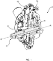
- FIG 1 shows a known high-pressure fuel pump, generally designated by 2, for a compression-ignition internal combustion engine.
- the high-pressure fuel pump (hereinafter “the pump 2") comprises a housing 4 and a driveshaft assembly 6 arranged for rotation within a bore 8 provided in the housing 4.
- the driveshaft assembly 6 comprises an elongate shaft element 10 (hereinafter “the shaft 10") and a cam member 12 secured to the shaft 10 by an interference fit formed by thermal shrink fitting.
- the driveshaft assembly 6 is caused, by a cam drive mechanism (not shown), to rotate relative to the housing 4 about longitudinal axis A. Rotation of the driveshaft assembly 6 causes a reciprocating force to be imparted to a plunger 14, via a roller 16, thereby causing fuel within a pumping chamber 18 to become pressurised.
- Figures 2a and 2b illustrate the driveshaft assembly 6 in isolation in an exploded view and an assembled view respectively.
- the shaft 10 has a circular cross-section and comprises a first journal portion 20 towards a first end 22 and a second journal portion 24 towards a second end 26.
- a mid-portion 28 is provided between the first journal portion 20 and the second journal portion 24.
- the cam member 12, comprising a thrust face 30, is secured to the mid-portion 28 of the shaft 10 by a thermal shrink fit.
- the cam member 12 When assembling the driveshaft assembly 6, the cam member 12 is heated, thereby causing a diameter a concentric circular through bore 32 (hereinafter “the bore 32") of the cam member 12 to radially expand.
- the diameter of the bore 32 prior to heating is 21mm.
- the heated cam member 12 is then inserted onto the shaft 10 via the second end 26 of the shaft 10, over the second journal portion 24, until it is located over the mid-portion 28 of the shaft 10.
- the cam member 12 is subsequently allowed to decrease in temperature in situ until its temperature equalises to room temperature. As the temperature of the cam member 12 decreases, the diameter of the bore 32 also decreases forming an interference fit on the mid-portion 28 of the shaft 10.
- an inner radial surface 34 defining the bore 32 of the cam member 12 is an interference fit on the outer radial surface 36 of the mid-portion 28 of the shaft 10.
- the interference between inner radial surface 34 and the outer radial surface 36 is in the region of 80 ⁇ m, resulting in an average contact pressure of approximately 225 MPa. Relative movement of the cam member 12 on the shaft 10 during use of the pump 2 is therefore prevented by the interference fit.
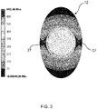
- FIG. 3 illustrates the hoop stress distribution in the cam member 12, and shows that the process described above results in a hoop stress concentration at narrow sections 37 of the cam member 12 having a peak value of approximately 680 MPa. It is because of this concentration of hoop stress that failure is seen at the narrow sections 37 of the cam member 12 during high load conditions.
- the present invention overcomes this problem by increasing the ovality of the bore 32 of the cam member 12 to provide an improved hoop stress distribution at the contact between the inner radial surface 34 of the cam member 12 and the outer radial surface 36 of the shaft 10.
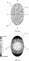
- FIG 4a shows an embodiment of a cam member 12 for use in a driveshaft assembly 6 in accordance with the invention.
- the cam member 12 comprises a concentric oval bore 38, having a minimum diameter of 21mm and a maximum diameter of 21.02mm. Accordingly, the ovality of the bore 38 is 0.095%.
- the shape of the cam member 12, defined an outer radial surface 40, and the oval bore 38 each comprises a major axis of symmetry, shown as line B - B, arranged perpendicularly with respect to a minor axis of symmetry, shown as line C - C. It can be seen from the figure that the oval bore 32 is arranged such that its the major and minor axes of symmetry are coaxially aligned with the respective major and minor axes of symmetry of the cam member 12.
- Figure 4b shows the hoop stress distribution in this embodiment of the cam member 12. It can be seen that the peak hoop stress at the narrow sections 37 of the cam member 12 is approximately 610 MPa, representing an 11% reduction in the peak hoop stress experience by the cam member 12 when compared to the cam member 12 having the circular bore 32. There are two reasons for this reduction in the peak hoop stress. Firstly, the presence of the oval bore 38 means that the circumferential interference between the inner radial surface 34 of the bore 38 and the outer radial surface 36 of the shaft 10 is not even.
- the interference at the narrow sections 37 of the cam member 12 is reduced to within the in the region of 60 ⁇ m, whereas the interference at the thicker sections of the cam member 12 stays within the region of 80 ⁇ m.
- This reduction in the interference at the narrow sections 37 of the cam member 12 leads to a corresponding reduction in the peak hoop stress experienced by the cam member 12 at those sections 37.
- a circular cam bore does not uniformly deform. Instead, the sides of the cam bore associated with the thicker sections of the cam member deform comparatively more than those associated with the thinner sections. This results in an uneven hoop stress distribution in the cam member and a large peak hoop stress.
- the deformation of the oval bore 38 during thermal shrink fitting is more uniform, allowing for a more even hoop stress distribution and a lower peak hoop stress.
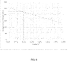
- the graphs of Figures 5 and 6 show that the peak hoop stress around the oval bore 38 (Cam bore) and the outer radial surface 40 (Cam OD) decreases with respect to ovality, and that the contact pressure between the inner radial surface 34 of the bore 38 and the outer radial surface 36 of the shaft 10 also decreases as the ovality of the bore 38 increases, respectively.
- Figure 6 shows that at an ovality of 0.095%, the average contact pressure between the inner radial surface 34 of the bore 38 and the outer radial surface 36 of the shaft 10 is approximately 225 MPa. This level of contact pressure is sufficient to prevent relative movement of the cam member 12 on the shaft 10 during use of the pump 2.
- a substantially lower contact pressure, produced by increasing the ovality of the bore 38, may not be sufficient to prevent relative movement between the cam member 12 and the shaft 10 during use of the pump 2.
- decreasing the ovality of the bore 38 too much would result in peak hoop stresses similar to those experienced by the cam member 12 having a circular bore 32, as shown in Figure 5 . Accordingly, it is preferable that the ovality of the bore 38 is within a range of 0.02% to 0.10%.
- the shaft 10 described above has a circular cross-section.
- at least the region of the shaft 10 to which the cam member 12 is secured by a thermal shrink fit, in this case the mid-portion 28 has an oval cross-section.
- the ovality of the mid-portion 28 may be substantially equal to the ovality of the bore 38.
- the major and minor axes of symmetry of the mid-portion 38 of the shaft 10 may be aligned with the respective major and minor axes of symmetry of the bore 38.
Landscapes
- Engineering & Computer Science (AREA)
- Mechanical Engineering (AREA)
- General Engineering & Computer Science (AREA)
- Chemical & Material Sciences (AREA)
- Combustion & Propulsion (AREA)
- Shafts, Cranks, Connecting Bars, And Related Bearings (AREA)
- Fuel-Injection Apparatus (AREA)
Claims (4)
- Antriebswellenanordnung (6) für eine Hochdruckkraftstoffpumpe (2), die Antriebswellenanordnung (6) umfassend ein längliches Wellenelement (10) und ein Nockenelement (12), umfassend eine konzentrische ovale Bohrung (38), wobei das Nockenelement (12) eine Presspassung auf dem länglichen Wellenelement (10) ist, wobei das Nockenelement (12) und die konzentrische ovale Bohrung (38) jeweils eine Hauptsymmetrieachse umfassen, die zu einer Nebensymmetrieachse senkrecht ist, wobei die konzentrische ovale Bohrung (38) in Bezug auf das Nockenelement (12) derart angeordnet ist, dass die Haupt- und Nebensymmetrieachsen der konzentrischen ovalen Bohrung (38) und des Nockenelements (12) koaxial ausgerichtet sind und
dadurch gekennzeichnet, dass der Abschnitt (28) des länglichen Wellenelements (10), der die Presspassung ausbildet, einen kreisförmigen Querschnitt aufweist. - Antriebswellenanordnung (6) nach dem vorhergehenden Anspruch, wobei die Ovalität der ovalen Bohrung (38) im Wesentlichen innerhalb des Bereichs von 0,02 % bis 0,10 % liegt.
- Antriebswellenanordnung (6) nach einem der vorhergehenden Ansprüche, wobei die Ovalität der ovalen Bohrung (38) im Wesentlichen 0,095 % beträgt.
- Hochdruckkraftstoffpumpe (2), umfassend eine Antriebswellenanordnung (6) nach einem der vorhergehenden Ansprüche.
Applications Claiming Priority (2)
| Application Number | Priority Date | Filing Date | Title |
|---|---|---|---|
| GB1809987.9A GB2575018B (en) | 2018-06-18 | 2018-06-18 | Fuel pump and driveshaft assembly therefor |
| PCT/EP2019/065952 WO2019243297A1 (en) | 2018-06-18 | 2019-06-18 | Fuel pump and driveshaft assembly therefor |
Publications (2)
| Publication Number | Publication Date |
|---|---|
| EP3807516A1 EP3807516A1 (de) | 2021-04-21 |
| EP3807516B1 true EP3807516B1 (de) | 2022-08-10 |
Family
ID=63042243
Family Applications (1)
| Application Number | Title | Priority Date | Filing Date |
|---|---|---|---|
| EP19731973.4A Active EP3807516B1 (de) | 2018-06-18 | 2019-06-18 | Kraftstoffpumpe und antriebswellenanordnung dafür |
Country Status (4)
| Country | Link |
|---|---|
| EP (1) | EP3807516B1 (de) |
| CN (1) | CN112292520A (de) |
| GB (1) | GB2575018B (de) |
| WO (1) | WO2019243297A1 (de) |
Family Cites Families (7)
| Publication number | Priority date | Publication date | Assignee | Title |
|---|---|---|---|---|
| CN1170051A (zh) * | 1996-05-09 | 1998-01-14 | Skf纺织机械部件有限公司 | 纺纱机的上罗拉托架的调节装置 |
| US5729899A (en) * | 1996-10-09 | 1998-03-24 | Kaywood Products Corporation | Camshaft assembly and method of making same |
| EP2557306A1 (de) * | 2011-08-08 | 2013-02-13 | Delphi Technologies Holding S.à.r.l. | Kraftstoffpumpe |
| DE102013208609A1 (de) * | 2013-05-10 | 2014-11-13 | Mahle International Gmbh | Nockenwelle |
| JP2015137712A (ja) * | 2014-01-22 | 2015-07-30 | トヨタ自動車株式会社 | カムシャフトの組み立て方法 |
| DE102014220384B4 (de) * | 2014-10-08 | 2021-02-18 | Vitesco Technologies GmbH | Kraftstoffhochdruckpumpe und Antriebswelle |
| CN107110093B (zh) * | 2014-12-17 | 2020-08-18 | 德尔福知识产权有限公司 | 传动轴 |
-
2018
- 2018-06-18 GB GB1809987.9A patent/GB2575018B/en active Active
-
2019
- 2019-06-18 EP EP19731973.4A patent/EP3807516B1/de active Active
- 2019-06-18 CN CN201980040855.8A patent/CN112292520A/zh active Pending
- 2019-06-18 WO PCT/EP2019/065952 patent/WO2019243297A1/en not_active Ceased
Also Published As
| Publication number | Publication date |
|---|---|
| GB2575018A (en) | 2020-01-01 |
| GB2575018B (en) | 2021-10-27 |
| WO2019243297A1 (en) | 2019-12-26 |
| EP3807516A1 (de) | 2021-04-21 |
| CN112292520A (zh) | 2021-01-29 |
| GB201809987D0 (en) | 2018-08-01 |
Similar Documents
| Publication | Publication Date | Title |
|---|---|---|
| US8230838B2 (en) | Injector seal assembly and method of sealing a coolant passage from an injector | |
| KR101682737B1 (ko) | 고압 펌프 | |
| US9382887B2 (en) | Engine component seal assembly and method of sealing a coolant passage from an engine component | |
| WO2016124660A1 (en) | Method to manufacture a common rail | |
| KR102211982B1 (ko) | 고압 매질을 안내하는 부품 | |
| EP3807516A1 (de) | Kraftstoffpumpe und antriebswellenanordnung dafür | |
| JP5040928B2 (ja) | 蓄圧器およびその製造方法 | |
| EP2235357B1 (de) | Mittel zum ausrichten und vorspannen von komponenten einer kraftstoffeinspritzdüsenanordnung | |
| US10508688B2 (en) | Bearing device and method of manufacturing the same | |
| KR102396682B1 (ko) | 드라이브샤프트 | |
| CN106232980A (zh) | 燃料泵 | |
| JP6692303B2 (ja) | 高圧燃料ポンプ | |
| JP7836296B2 (ja) | 燃料ポンプ装置、システム、及び方法 | |
| CN103998763A (zh) | 燃料供给泵 | |
| US7966993B2 (en) | Fuel injection pump having a barrel expansion control sleeve | |
| KR102447585B1 (ko) | 연료 분사 시스템의 장치 및 금속 밀봉 연결 유닛 | |
| US12577928B2 (en) | Pump actuator with improved fatigue life | |
| US20170184050A1 (en) | Cylinder block for engine | |
| US10309393B2 (en) | High-pressure pump and production method thereof | |
| US9651013B2 (en) | Low leakage seat valve guide | |
| EP3124759A1 (de) | Rollenvorrichtung, stift zur verwendung in einer rollenvorrichtung und verfahren zum verriegeln eines stiftes | |
| JPH0599091A (ja) | 分配型燃料噴射ポンプ | |
| US20150198230A1 (en) | Cam follower assembly having swaged bushing | |
| GB2577324A (en) | A HP pump of a fuel injection system provided with a camshaft assembly | |
| JP2012163077A (ja) | 金属ボディの製造方法、金属ボディおよび燃料供給ポンプ |
Legal Events
| Date | Code | Title | Description |
|---|---|---|---|
| STAA | Information on the status of an ep patent application or granted ep patent |
Free format text: STATUS: UNKNOWN |
|
| STAA | Information on the status of an ep patent application or granted ep patent |
Free format text: STATUS: THE INTERNATIONAL PUBLICATION HAS BEEN MADE |
|
| PUAI | Public reference made under article 153(3) epc to a published international application that has entered the european phase |
Free format text: ORIGINAL CODE: 0009012 |
|
| STAA | Information on the status of an ep patent application or granted ep patent |
Free format text: STATUS: REQUEST FOR EXAMINATION WAS MADE |
|
| 17P | Request for examination filed |
Effective date: 20210118 |
|
| AK | Designated contracting states |
Kind code of ref document: A1 Designated state(s): AL AT BE BG CH CY CZ DE DK EE ES FI FR GB GR HR HU IE IS IT LI LT LU LV MC MK MT NL NO PL PT RO RS SE SI SK SM TR |
|
| AX | Request for extension of the european patent |
Extension state: BA ME |
|
| DAV | Request for validation of the european patent (deleted) | ||
| DAX | Request for extension of the european patent (deleted) | ||
| REG | Reference to a national code |
Ref country code: DE Ref legal event code: R079 Ref document number: 602019018142 Country of ref document: DE Free format text: PREVIOUS MAIN CLASS: F02M0059480000 Ipc: F04B0001041300 |
|
| GRAP | Despatch of communication of intention to grant a patent |
Free format text: ORIGINAL CODE: EPIDOSNIGR1 |
|
| RIC1 | Information provided on ipc code assigned before grant |
Ipc: F04B 1/0413 20200101AFI20220307BHEP |
|
| INTG | Intention to grant announced |
Effective date: 20220324 |
|
| STAA | Information on the status of an ep patent application or granted ep patent |
Free format text: STATUS: GRANT OF PATENT IS INTENDED |
|
| GRAS | Grant fee paid |
Free format text: ORIGINAL CODE: EPIDOSNIGR3 |
|
| GRAA | (expected) grant |
Free format text: ORIGINAL CODE: 0009210 |
|
| STAA | Information on the status of an ep patent application or granted ep patent |
Free format text: STATUS: THE PATENT HAS BEEN GRANTED |
|
| AK | Designated contracting states |
Kind code of ref document: B1 Designated state(s): AL AT BE BG CH CY CZ DE DK EE ES FI FR GB GR HR HU IE IS IT LI LT LU LV MC MK MT NL NO PL PT RO RS SE SI SK SM TR |
|
| REG | Reference to a national code |
Ref country code: AT Ref legal event code: REF Ref document number: 1510725 Country of ref document: AT Kind code of ref document: T Effective date: 20220815 Ref country code: CH Ref legal event code: EP |
|
| REG | Reference to a national code |
Ref country code: IE Ref legal event code: FG4D |
|
| REG | Reference to a national code |
Ref country code: DE Ref legal event code: R096 Ref document number: 602019018142 Country of ref document: DE |
|
| GRAP | Despatch of communication of intention to grant a patent |
Free format text: ORIGINAL CODE: EPIDOSNIGR1 |
|
| RAP4 | Party data changed (patent owner data changed or rights of a patent transferred) |
Owner name: DELPHI TECHNOLOGIES IP LIMITED |
|
| REG | Reference to a national code |
Ref country code: DE Ref legal event code: R081 Ref document number: 602019018142 Country of ref document: DE Owner name: DELPHI TECHNOLOGIES IP LIMITED, BB Free format text: FORMER OWNER: DELPHI TECHNOLOGIES IP LIMITED, SAINT MICHAEL, BB Ref country code: DE Ref legal event code: R081 Ref document number: 602019018142 Country of ref document: DE Owner name: PHINIA DELPHI LUXEMBOURG SARL, LU Free format text: FORMER OWNER: DELPHI TECHNOLOGIES IP LIMITED, SAINT MICHAEL, BB |
|
| REG | Reference to a national code |
Ref country code: NL Ref legal event code: MP Effective date: 20220810 |
|
| REG | Reference to a national code |
Ref country code: LT Ref legal event code: MG9D |
|
| PG25 | Lapsed in a contracting state [announced via postgrant information from national office to epo] |
Ref country code: SE Free format text: LAPSE BECAUSE OF FAILURE TO SUBMIT A TRANSLATION OF THE DESCRIPTION OR TO PAY THE FEE WITHIN THE PRESCRIBED TIME-LIMIT Effective date: 20220810 Ref country code: RS Free format text: LAPSE BECAUSE OF FAILURE TO SUBMIT A TRANSLATION OF THE DESCRIPTION OR TO PAY THE FEE WITHIN THE PRESCRIBED TIME-LIMIT Effective date: 20220810 Ref country code: PT Free format text: LAPSE BECAUSE OF FAILURE TO SUBMIT A TRANSLATION OF THE DESCRIPTION OR TO PAY THE FEE WITHIN THE PRESCRIBED TIME-LIMIT Effective date: 20221212 Ref country code: NO Free format text: LAPSE BECAUSE OF FAILURE TO SUBMIT A TRANSLATION OF THE DESCRIPTION OR TO PAY THE FEE WITHIN THE PRESCRIBED TIME-LIMIT Effective date: 20221110 Ref country code: NL Free format text: LAPSE BECAUSE OF FAILURE TO SUBMIT A TRANSLATION OF THE DESCRIPTION OR TO PAY THE FEE WITHIN THE PRESCRIBED TIME-LIMIT Effective date: 20220810 Ref country code: LV Free format text: LAPSE BECAUSE OF FAILURE TO SUBMIT A TRANSLATION OF THE DESCRIPTION OR TO PAY THE FEE WITHIN THE PRESCRIBED TIME-LIMIT Effective date: 20220810 Ref country code: LT Free format text: LAPSE BECAUSE OF FAILURE TO SUBMIT A TRANSLATION OF THE DESCRIPTION OR TO PAY THE FEE WITHIN THE PRESCRIBED TIME-LIMIT Effective date: 20220810 Ref country code: FI Free format text: LAPSE BECAUSE OF FAILURE TO SUBMIT A TRANSLATION OF THE DESCRIPTION OR TO PAY THE FEE WITHIN THE PRESCRIBED TIME-LIMIT Effective date: 20220810 |
|
| REG | Reference to a national code |
Ref country code: AT Ref legal event code: MK05 Ref document number: 1510725 Country of ref document: AT Kind code of ref document: T Effective date: 20220810 |
|
| PG25 | Lapsed in a contracting state [announced via postgrant information from national office to epo] |
Ref country code: PL Free format text: LAPSE BECAUSE OF FAILURE TO SUBMIT A TRANSLATION OF THE DESCRIPTION OR TO PAY THE FEE WITHIN THE PRESCRIBED TIME-LIMIT Effective date: 20220810 Ref country code: IS Free format text: LAPSE BECAUSE OF FAILURE TO SUBMIT A TRANSLATION OF THE DESCRIPTION OR TO PAY THE FEE WITHIN THE PRESCRIBED TIME-LIMIT Effective date: 20221210 Ref country code: HR Free format text: LAPSE BECAUSE OF FAILURE TO SUBMIT A TRANSLATION OF THE DESCRIPTION OR TO PAY THE FEE WITHIN THE PRESCRIBED TIME-LIMIT Effective date: 20220810 Ref country code: GR Free format text: LAPSE BECAUSE OF FAILURE TO SUBMIT A TRANSLATION OF THE DESCRIPTION OR TO PAY THE FEE WITHIN THE PRESCRIBED TIME-LIMIT Effective date: 20221111 |
|
| PG25 | Lapsed in a contracting state [announced via postgrant information from national office to epo] |
Ref country code: SM Free format text: LAPSE BECAUSE OF FAILURE TO SUBMIT A TRANSLATION OF THE DESCRIPTION OR TO PAY THE FEE WITHIN THE PRESCRIBED TIME-LIMIT Effective date: 20220810 Ref country code: RO Free format text: LAPSE BECAUSE OF FAILURE TO SUBMIT A TRANSLATION OF THE DESCRIPTION OR TO PAY THE FEE WITHIN THE PRESCRIBED TIME-LIMIT Effective date: 20220810 Ref country code: ES Free format text: LAPSE BECAUSE OF FAILURE TO SUBMIT A TRANSLATION OF THE DESCRIPTION OR TO PAY THE FEE WITHIN THE PRESCRIBED TIME-LIMIT Effective date: 20220810 Ref country code: DK Free format text: LAPSE BECAUSE OF FAILURE TO SUBMIT A TRANSLATION OF THE DESCRIPTION OR TO PAY THE FEE WITHIN THE PRESCRIBED TIME-LIMIT Effective date: 20220810 Ref country code: CZ Free format text: LAPSE BECAUSE OF FAILURE TO SUBMIT A TRANSLATION OF THE DESCRIPTION OR TO PAY THE FEE WITHIN THE PRESCRIBED TIME-LIMIT Effective date: 20220810 Ref country code: AT Free format text: LAPSE BECAUSE OF FAILURE TO SUBMIT A TRANSLATION OF THE DESCRIPTION OR TO PAY THE FEE WITHIN THE PRESCRIBED TIME-LIMIT Effective date: 20220810 |
|
| REG | Reference to a national code |
Ref country code: DE Ref legal event code: R097 Ref document number: 602019018142 Country of ref document: DE |
|
| PG25 | Lapsed in a contracting state [announced via postgrant information from national office to epo] |
Ref country code: SK Free format text: LAPSE BECAUSE OF FAILURE TO SUBMIT A TRANSLATION OF THE DESCRIPTION OR TO PAY THE FEE WITHIN THE PRESCRIBED TIME-LIMIT Effective date: 20220810 Ref country code: EE Free format text: LAPSE BECAUSE OF FAILURE TO SUBMIT A TRANSLATION OF THE DESCRIPTION OR TO PAY THE FEE WITHIN THE PRESCRIBED TIME-LIMIT Effective date: 20220810 |
|
| P01 | Opt-out of the competence of the unified patent court (upc) registered |
Effective date: 20230327 |
|
| PLBE | No opposition filed within time limit |
Free format text: ORIGINAL CODE: 0009261 |
|
| STAA | Information on the status of an ep patent application or granted ep patent |
Free format text: STATUS: NO OPPOSITION FILED WITHIN TIME LIMIT |
|
| PG25 | Lapsed in a contracting state [announced via postgrant information from national office to epo] |
Ref country code: AL Free format text: LAPSE BECAUSE OF FAILURE TO SUBMIT A TRANSLATION OF THE DESCRIPTION OR TO PAY THE FEE WITHIN THE PRESCRIBED TIME-LIMIT Effective date: 20220810 |
|
| 26N | No opposition filed |
Effective date: 20230511 |
|
| PG25 | Lapsed in a contracting state [announced via postgrant information from national office to epo] |
Ref country code: SI Free format text: LAPSE BECAUSE OF FAILURE TO SUBMIT A TRANSLATION OF THE DESCRIPTION OR TO PAY THE FEE WITHIN THE PRESCRIBED TIME-LIMIT Effective date: 20220810 |
|
| PG25 | Lapsed in a contracting state [announced via postgrant information from national office to epo] |
Ref country code: MC Free format text: LAPSE BECAUSE OF FAILURE TO SUBMIT A TRANSLATION OF THE DESCRIPTION OR TO PAY THE FEE WITHIN THE PRESCRIBED TIME-LIMIT Effective date: 20220810 |
|
| PG25 | Lapsed in a contracting state [announced via postgrant information from national office to epo] |
Ref country code: MC Free format text: LAPSE BECAUSE OF FAILURE TO SUBMIT A TRANSLATION OF THE DESCRIPTION OR TO PAY THE FEE WITHIN THE PRESCRIBED TIME-LIMIT Effective date: 20220810 |
|
| REG | Reference to a national code |
Ref country code: CH Ref legal event code: PL |
|
| REG | Reference to a national code |
Ref country code: BE Ref legal event code: MM Effective date: 20230630 |
|
| PG25 | Lapsed in a contracting state [announced via postgrant information from national office to epo] |
Ref country code: LU Free format text: LAPSE BECAUSE OF NON-PAYMENT OF DUE FEES Effective date: 20230618 |
|
| REG | Reference to a national code |
Ref country code: IE Ref legal event code: MM4A |
|
| PG25 | Lapsed in a contracting state [announced via postgrant information from national office to epo] |
Ref country code: LU Free format text: LAPSE BECAUSE OF NON-PAYMENT OF DUE FEES Effective date: 20230618 |
|
| PG25 | Lapsed in a contracting state [announced via postgrant information from national office to epo] |
Ref country code: IE Free format text: LAPSE BECAUSE OF NON-PAYMENT OF DUE FEES Effective date: 20230618 |
|
| REG | Reference to a national code |
Ref country code: DE Ref legal event code: R081 Ref document number: 602019018142 Country of ref document: DE Owner name: PHINIA DELPHI LUXEMBOURG SARL, LU Free format text: FORMER OWNER: DELPHI TECHNOLOGIES IP LIMITED, ST MICHAEL, BB |
|
| PG25 | Lapsed in a contracting state [announced via postgrant information from national office to epo] |
Ref country code: IE Free format text: LAPSE BECAUSE OF NON-PAYMENT OF DUE FEES Effective date: 20230618 Ref country code: CH Free format text: LAPSE BECAUSE OF NON-PAYMENT OF DUE FEES Effective date: 20230630 |
|
| REG | Reference to a national code |
Ref country code: GB Ref legal event code: 732E Free format text: REGISTERED BETWEEN 20240411 AND 20240417 |
|
| PG25 | Lapsed in a contracting state [announced via postgrant information from national office to epo] |
Ref country code: IT Free format text: LAPSE BECAUSE OF FAILURE TO SUBMIT A TRANSLATION OF THE DESCRIPTION OR TO PAY THE FEE WITHIN THE PRESCRIBED TIME-LIMIT Effective date: 20220810 Ref country code: BE Free format text: LAPSE BECAUSE OF NON-PAYMENT OF DUE FEES Effective date: 20230630 |
|
| PG25 | Lapsed in a contracting state [announced via postgrant information from national office to epo] |
Ref country code: BG Free format text: LAPSE BECAUSE OF FAILURE TO SUBMIT A TRANSLATION OF THE DESCRIPTION OR TO PAY THE FEE WITHIN THE PRESCRIBED TIME-LIMIT Effective date: 20220810 |
|
| PG25 | Lapsed in a contracting state [announced via postgrant information from national office to epo] |
Ref country code: BG Free format text: LAPSE BECAUSE OF FAILURE TO SUBMIT A TRANSLATION OF THE DESCRIPTION OR TO PAY THE FEE WITHIN THE PRESCRIBED TIME-LIMIT Effective date: 20220810 |
|
| PGFP | Annual fee paid to national office [announced via postgrant information from national office to epo] |
Ref country code: DE Payment date: 20250509 Year of fee payment: 7 |
|
| PGFP | Annual fee paid to national office [announced via postgrant information from national office to epo] |
Ref country code: GB Payment date: 20250508 Year of fee payment: 7 |
|
| PGFP | Annual fee paid to national office [announced via postgrant information from national office to epo] |
Ref country code: FR Payment date: 20250512 Year of fee payment: 7 |
|
| PG25 | Lapsed in a contracting state [announced via postgrant information from national office to epo] |
Ref country code: CY Free format text: LAPSE BECAUSE OF FAILURE TO SUBMIT A TRANSLATION OF THE DESCRIPTION OR TO PAY THE FEE WITHIN THE PRESCRIBED TIME-LIMIT; INVALID AB INITIO Effective date: 20190618 |
|
| PG25 | Lapsed in a contracting state [announced via postgrant information from national office to epo] |
Ref country code: HU Free format text: LAPSE BECAUSE OF FAILURE TO SUBMIT A TRANSLATION OF THE DESCRIPTION OR TO PAY THE FEE WITHIN THE PRESCRIBED TIME-LIMIT; INVALID AB INITIO Effective date: 20190618 |
|
| PG25 | Lapsed in a contracting state [announced via postgrant information from national office to epo] |
Ref country code: TR Free format text: LAPSE BECAUSE OF FAILURE TO SUBMIT A TRANSLATION OF THE DESCRIPTION OR TO PAY THE FEE WITHIN THE PRESCRIBED TIME-LIMIT Effective date: 20220810 |