EP3806269A1 - Moving body positioning station and moving body positioning system - Google Patents
Moving body positioning station and moving body positioning system Download PDFInfo
- Publication number
- EP3806269A1 EP3806269A1 EP19815170.6A EP19815170A EP3806269A1 EP 3806269 A1 EP3806269 A1 EP 3806269A1 EP 19815170 A EP19815170 A EP 19815170A EP 3806269 A1 EP3806269 A1 EP 3806269A1
- Authority
- EP
- European Patent Office
- Prior art keywords
- partition
- mobile body
- robot
- guide
- positioning station
- Prior art date
- Legal status (The legal status is an assumption and is not a legal conclusion. Google has not performed a legal analysis and makes no representation as to the accuracy of the status listed.)
- Granted
Links
Images






Classifications
-
- H—ELECTRICITY
- H02—GENERATION; CONVERSION OR DISTRIBUTION OF ELECTRIC POWER
- H02J—ELECTRIC POWER NETWORKS; CIRCUIT ARRANGEMENTS OR SYSTEMS FOR SUPPLYING OR DISTRIBUTING ELECTRIC POWER; SYSTEMS FOR STORING ELECTRIC ENERGY
- H02J7/00—Circuit arrangements for charging or discharging batteries or for supplying loads from batteries
- H02J7/70—Circuit arrangements for charging or discharging batteries or for supplying loads from batteries characterised by the mechanical construction
-
- B—PERFORMING OPERATIONS; TRANSPORTING
- B65—CONVEYING; PACKING; STORING; HANDLING THIN OR FILAMENTARY MATERIAL
- B65G—TRANSPORT OR STORAGE DEVICES, e.g. CONVEYORS FOR LOADING OR TIPPING, SHOP CONVEYOR SYSTEMS OR PNEUMATIC TUBE CONVEYORS
- B65G47/00—Article or material-handling devices associated with conveyors; Methods employing such devices
- B65G47/22—Devices influencing the relative position or the attitude of articles during transit by conveyors
-
- B—PERFORMING OPERATIONS; TRANSPORTING
- B60—VEHICLES IN GENERAL
- B60L—PROPULSION OF ELECTRICALLY-PROPELLED VEHICLES; SUPPLYING ELECTRIC POWER FOR AUXILIARY EQUIPMENT OF ELECTRICALLY-PROPELLED VEHICLES; ELECTRODYNAMIC BRAKE SYSTEMS FOR VEHICLES IN GENERAL; MAGNETIC SUSPENSION OR LEVITATION FOR VEHICLES; MONITORING OPERATING VARIABLES OF ELECTRICALLY-PROPELLED VEHICLES; ELECTRIC SAFETY DEVICES FOR ELECTRICALLY-PROPELLED VEHICLES
- B60L53/00—Methods of charging batteries, specially adapted for electric vehicles; Charging stations or on-board charging equipment therefor; Exchange of energy storage elements in electric vehicles
- B60L53/10—Methods of charging batteries, specially adapted for electric vehicles; Charging stations or on-board charging equipment therefor; Exchange of energy storage elements in electric vehicles characterised by the energy transfer between the charging station and the vehicle
- B60L53/14—Conductive energy transfer
-
- B—PERFORMING OPERATIONS; TRANSPORTING
- B60—VEHICLES IN GENERAL
- B60L—PROPULSION OF ELECTRICALLY-PROPELLED VEHICLES; SUPPLYING ELECTRIC POWER FOR AUXILIARY EQUIPMENT OF ELECTRICALLY-PROPELLED VEHICLES; ELECTRODYNAMIC BRAKE SYSTEMS FOR VEHICLES IN GENERAL; MAGNETIC SUSPENSION OR LEVITATION FOR VEHICLES; MONITORING OPERATING VARIABLES OF ELECTRICALLY-PROPELLED VEHICLES; ELECTRIC SAFETY DEVICES FOR ELECTRICALLY-PROPELLED VEHICLES
- B60L53/00—Methods of charging batteries, specially adapted for electric vehicles; Charging stations or on-board charging equipment therefor; Exchange of energy storage elements in electric vehicles
- B60L53/30—Constructional details of charging stations
- B60L53/35—Means for automatic or assisted adjustment of the relative position of charging devices and vehicles
- B60L53/36—Means for automatic or assisted adjustment of the relative position of charging devices and vehicles by positioning the vehicle
-
- B—PERFORMING OPERATIONS; TRANSPORTING
- B60—VEHICLES IN GENERAL
- B60L—PROPULSION OF ELECTRICALLY-PROPELLED VEHICLES; SUPPLYING ELECTRIC POWER FOR AUXILIARY EQUIPMENT OF ELECTRICALLY-PROPELLED VEHICLES; ELECTRODYNAMIC BRAKE SYSTEMS FOR VEHICLES IN GENERAL; MAGNETIC SUSPENSION OR LEVITATION FOR VEHICLES; MONITORING OPERATING VARIABLES OF ELECTRICALLY-PROPELLED VEHICLES; ELECTRIC SAFETY DEVICES FOR ELECTRICALLY-PROPELLED VEHICLES
- B60L53/00—Methods of charging batteries, specially adapted for electric vehicles; Charging stations or on-board charging equipment therefor; Exchange of energy storage elements in electric vehicles
- B60L53/30—Constructional details of charging stations
- B60L53/35—Means for automatic or assisted adjustment of the relative position of charging devices and vehicles
- B60L53/37—Means for automatic or assisted adjustment of the relative position of charging devices and vehicles using optical position determination, e.g. using cameras
-
- B—PERFORMING OPERATIONS; TRANSPORTING
- B65—CONVEYING; PACKING; STORING; HANDLING THIN OR FILAMENTARY MATERIAL
- B65G—TRANSPORT OR STORAGE DEVICES, e.g. CONVEYORS FOR LOADING OR TIPPING, SHOP CONVEYOR SYSTEMS OR PNEUMATIC TUBE CONVEYORS
- B65G17/00—Conveyors having an endless traction element, e.g. a chain, transmitting movement to a continuous or substantially-continuous load-carrying surface or to a series of individual load-carriers; Endless-chain conveyors in which the chains form the load-carrying surface
- B65G17/16—Conveyors having an endless traction element, e.g. a chain, transmitting movement to a continuous or substantially-continuous load-carrying surface or to a series of individual load-carriers; Endless-chain conveyors in which the chains form the load-carrying surface comprising individual load-carriers which are pivotally mounted, e.g. for free-swinging movement
- B65G17/18—Conveyors having an endless traction element, e.g. a chain, transmitting movement to a continuous or substantially-continuous load-carrying surface or to a series of individual load-carriers; Endless-chain conveyors in which the chains form the load-carrying surface comprising individual load-carriers which are pivotally mounted, e.g. for free-swinging movement and move in contact with a guiding surface
-
- B—PERFORMING OPERATIONS; TRANSPORTING
- B65—CONVEYING; PACKING; STORING; HANDLING THIN OR FILAMENTARY MATERIAL
- B65G—TRANSPORT OR STORAGE DEVICES, e.g. CONVEYORS FOR LOADING OR TIPPING, SHOP CONVEYOR SYSTEMS OR PNEUMATIC TUBE CONVEYORS
- B65G39/00—Rollers, e.g. drive rollers, or arrangements thereof incorporated in roller-ways or other types of mechanical conveyors
- B65G39/10—Arrangements of rollers
- B65G39/12—Arrangements of rollers mounted on framework
- B65G39/18—Arrangements of rollers mounted on framework for guiding loads
-
- B—PERFORMING OPERATIONS; TRANSPORTING
- B65—CONVEYING; PACKING; STORING; HANDLING THIN OR FILAMENTARY MATERIAL
- B65G—TRANSPORT OR STORAGE DEVICES, e.g. CONVEYORS FOR LOADING OR TIPPING, SHOP CONVEYOR SYSTEMS OR PNEUMATIC TUBE CONVEYORS
- B65G41/00—Supporting frames or bases for conveyors as a whole, e.g. transportable conveyor frames
- B65G41/006—Supporting frames or bases for conveyors as a whole, e.g. transportable conveyor frames with the conveyor not adjustably mounted on the supporting frame or base
-
- G—PHYSICS
- G05—CONTROLLING; REGULATING
- G05D—SYSTEMS FOR CONTROLLING OR REGULATING NON-ELECTRIC VARIABLES
- G05D1/00—Control of position, course, altitude or attitude of land, water, air or space vehicles, e.g. using automatic pilots
- G05D1/02—Control of position or course in two dimensions
- G05D1/021—Control of position or course in two dimensions specially adapted to land vehicles
- G05D1/0212—Control of position or course in two dimensions specially adapted to land vehicles with means for defining a desired trajectory
- G05D1/0225—Control of position or course in two dimensions specially adapted to land vehicles with means for defining a desired trajectory involving docking at a fixed facility, e.g. base station or loading bay
-
- G—PHYSICS
- G05—CONTROLLING; REGULATING
- G05D—SYSTEMS FOR CONTROLLING OR REGULATING NON-ELECTRIC VARIABLES
- G05D1/00—Control of position, course, altitude or attitude of land, water, air or space vehicles, e.g. using automatic pilots
- G05D1/02—Control of position or course in two dimensions
- G05D1/021—Control of position or course in two dimensions specially adapted to land vehicles
- G05D1/0227—Control of position or course in two dimensions specially adapted to land vehicles using mechanical sensing means, e.g. for sensing treated area
-
- B—PERFORMING OPERATIONS; TRANSPORTING
- B60—VEHICLES IN GENERAL
- B60L—PROPULSION OF ELECTRICALLY-PROPELLED VEHICLES; SUPPLYING ELECTRIC POWER FOR AUXILIARY EQUIPMENT OF ELECTRICALLY-PROPELLED VEHICLES; ELECTRODYNAMIC BRAKE SYSTEMS FOR VEHICLES IN GENERAL; MAGNETIC SUSPENSION OR LEVITATION FOR VEHICLES; MONITORING OPERATING VARIABLES OF ELECTRICALLY-PROPELLED VEHICLES; ELECTRIC SAFETY DEVICES FOR ELECTRICALLY-PROPELLED VEHICLES
- B60L2260/00—Operating Modes
- B60L2260/20—Drive modes; Transition between modes
- B60L2260/32—Auto pilot mode
-
- B—PERFORMING OPERATIONS; TRANSPORTING
- B65—CONVEYING; PACKING; STORING; HANDLING THIN OR FILAMENTARY MATERIAL
- B65G—TRANSPORT OR STORAGE DEVICES, e.g. CONVEYORS FOR LOADING OR TIPPING, SHOP CONVEYOR SYSTEMS OR PNEUMATIC TUBE CONVEYORS
- B65G13/00—Roller-ways
- B65G13/11—Roller frames
-
- F—MECHANICAL ENGINEERING; LIGHTING; HEATING; WEAPONS; BLASTING
- F16—ENGINEERING ELEMENTS AND UNITS; GENERAL MEASURES FOR PRODUCING AND MAINTAINING EFFECTIVE FUNCTIONING OF MACHINES OR INSTALLATIONS; THERMAL INSULATION IN GENERAL
- F16C—SHAFTS; FLEXIBLE SHAFTS; ELEMENTS OR CRANKSHAFT MECHANISMS; ROTARY BODIES OTHER THAN GEARING ELEMENTS; BEARINGS
- F16C2326/00—Articles relating to transporting
-
- F—MECHANICAL ENGINEERING; LIGHTING; HEATING; WEAPONS; BLASTING
- F16—ENGINEERING ELEMENTS AND UNITS; GENERAL MEASURES FOR PRODUCING AND MAINTAINING EFFECTIVE FUNCTIONING OF MACHINES OR INSTALLATIONS; THERMAL INSULATION IN GENERAL
- F16H—GEARING
- F16H57/00—General details of gearing
- F16H2057/0093—Means or measures for transport, shipping or packaging
-
- G—PHYSICS
- G05—CONTROLLING; REGULATING
- G05B—CONTROL OR REGULATING SYSTEMS IN GENERAL; FUNCTIONAL ELEMENTS OF SUCH SYSTEMS; MONITORING OR TESTING ARRANGEMENTS FOR SUCH SYSTEMS OR ELEMENTS
- G05B19/00—Program-control systems
- G05B19/02—Program-control systems electric
- G05B19/418—Total factory control, i.e. centrally controlling a plurality of machines, e.g. direct or distributed numerical control [DNC], flexible manufacturing systems [FMS], integrated manufacturing systems [IMS] or computer integrated manufacturing [CIM]
- G05B19/4189—Total factory control, i.e. centrally controlling a plurality of machines, e.g. direct or distributed numerical control [DNC], flexible manufacturing systems [FMS], integrated manufacturing systems [IMS] or computer integrated manufacturing [CIM] characterised by the transport system
-
- Y—GENERAL TAGGING OF NEW TECHNOLOGICAL DEVELOPMENTS; GENERAL TAGGING OF CROSS-SECTIONAL TECHNOLOGIES SPANNING OVER SEVERAL SECTIONS OF THE IPC; TECHNICAL SUBJECTS COVERED BY FORMER USPC CROSS-REFERENCE ART COLLECTIONS [XRACs] AND DIGESTS
- Y02—TECHNOLOGIES OR APPLICATIONS FOR MITIGATION OR ADAPTATION AGAINST CLIMATE CHANGE
- Y02T—CLIMATE CHANGE MITIGATION TECHNOLOGIES RELATED TO TRANSPORTATION
- Y02T10/00—Road transport of goods or passengers
- Y02T10/60—Other road transportation technologies with climate change mitigation effect
- Y02T10/70—Energy storage systems for electromobility, e.g. batteries
-
- Y—GENERAL TAGGING OF NEW TECHNOLOGICAL DEVELOPMENTS; GENERAL TAGGING OF CROSS-SECTIONAL TECHNOLOGIES SPANNING OVER SEVERAL SECTIONS OF THE IPC; TECHNICAL SUBJECTS COVERED BY FORMER USPC CROSS-REFERENCE ART COLLECTIONS [XRACs] AND DIGESTS
- Y02—TECHNOLOGIES OR APPLICATIONS FOR MITIGATION OR ADAPTATION AGAINST CLIMATE CHANGE
- Y02T—CLIMATE CHANGE MITIGATION TECHNOLOGIES RELATED TO TRANSPORTATION
- Y02T10/00—Road transport of goods or passengers
- Y02T10/60—Other road transportation technologies with climate change mitigation effect
- Y02T10/7072—Electromobility specific charging systems or methods for batteries, ultracapacitors, supercapacitors or double-layer capacitors
-
- Y—GENERAL TAGGING OF NEW TECHNOLOGICAL DEVELOPMENTS; GENERAL TAGGING OF CROSS-SECTIONAL TECHNOLOGIES SPANNING OVER SEVERAL SECTIONS OF THE IPC; TECHNICAL SUBJECTS COVERED BY FORMER USPC CROSS-REFERENCE ART COLLECTIONS [XRACs] AND DIGESTS
- Y02—TECHNOLOGIES OR APPLICATIONS FOR MITIGATION OR ADAPTATION AGAINST CLIMATE CHANGE
- Y02T—CLIMATE CHANGE MITIGATION TECHNOLOGIES RELATED TO TRANSPORTATION
- Y02T10/00—Road transport of goods or passengers
- Y02T10/60—Other road transportation technologies with climate change mitigation effect
- Y02T10/72—Electric energy management in electromobility
-
- Y—GENERAL TAGGING OF NEW TECHNOLOGICAL DEVELOPMENTS; GENERAL TAGGING OF CROSS-SECTIONAL TECHNOLOGIES SPANNING OVER SEVERAL SECTIONS OF THE IPC; TECHNICAL SUBJECTS COVERED BY FORMER USPC CROSS-REFERENCE ART COLLECTIONS [XRACs] AND DIGESTS
- Y02—TECHNOLOGIES OR APPLICATIONS FOR MITIGATION OR ADAPTATION AGAINST CLIMATE CHANGE
- Y02T—CLIMATE CHANGE MITIGATION TECHNOLOGIES RELATED TO TRANSPORTATION
- Y02T90/00—Enabling technologies or technologies with a potential or indirect contribution to GHG emissions mitigation
- Y02T90/10—Technologies relating to charging of electric vehicles
- Y02T90/12—Electric charging stations
-
- Y—GENERAL TAGGING OF NEW TECHNOLOGICAL DEVELOPMENTS; GENERAL TAGGING OF CROSS-SECTIONAL TECHNOLOGIES SPANNING OVER SEVERAL SECTIONS OF THE IPC; TECHNICAL SUBJECTS COVERED BY FORMER USPC CROSS-REFERENCE ART COLLECTIONS [XRACs] AND DIGESTS
- Y02—TECHNOLOGIES OR APPLICATIONS FOR MITIGATION OR ADAPTATION AGAINST CLIMATE CHANGE
- Y02T—CLIMATE CHANGE MITIGATION TECHNOLOGIES RELATED TO TRANSPORTATION
- Y02T90/00—Enabling technologies or technologies with a potential or indirect contribution to GHG emissions mitigation
- Y02T90/10—Technologies relating to charging of electric vehicles
- Y02T90/14—Plug-in electric vehicles
Definitions
- the present invention relates to a mobile body positioning station and a mobile body positioning system that positions a movable mobile body at a predetermined position to perform various kinds of work.
- the robot In patrol inspection work or the like using a movable robot, the robot needs to perform various kinds of work, such as refueling and maintenance work. In this case, when performing patrol inspection work or the like, the robot is self-propelled to a station to perform these various kinds of work.
- the patrol inspection work is performed in, for example, a petrochemical plant, if a substance such as petroleum leaks, the work environment of the robot will become an explosive atmosphere to cause a fire upon ignition with sparks generated at actuation of the robot. Consequently, in this case, the robot needs to have an explosion-proof structure.
- Patent Literature 1 an explosion-proof structure of a conventional robot is described in Patent Literature 1 below.
- An industrial robot described in Patent Literature 1 includes a control device, a battery, and a motor that are disposed on a movable frame, and has an internal pressure explosion-proof structure in which air is supplied into the frame from an air supply device so as to maintain the inside the frame at a pressure higher than a predetermined pressure.
- Patent Literature 1 JP 2015-036172 A
- the present invention has been made to solve the above-described problem, and an object of the present invention is to provide a mobile body positioning station and a mobile body positioning system that have simplified configurations.
- a mobile body positioning station includes a first partition; a second partition disposed along a direction intersecting an extending direction of the first partition; and a guide disposed on a movement path of a mobile body.
- the guide is disposed along an oblique direction with respect to a direction perpendicular to the extending direction of the first partition to extend from the first partition toward the second partition side.
- the guide is configured to make the mobile body move in the oblique direction more easily than move in directions other than the oblique direction, and the guide is configured to move the mobile body along the first partition toward the second partition.
- the guide guides the mobile body toward the second partition along the oblique direction in which the mobile body moves easily.
- the guide stops guiding the mobile body, and the positioning at the one side of the mobile body is done.
- the guide is configured to cause the mobile body to move along the first partition toward the second partition after the mobile body comes into contact with the first partition.
- the guide causes the mobile body to move toward the second partition so that the mobile body can be positioned with the simple configuration.
- the guide is configured to cause the mobile body to move toward the second partition with use of movement driving force of the mobile body.
- the movement driving force of the mobile body can make the guide function to efficiently move and guide the mobile body toward the second partition.
- the oblique direction is a direction inclined at a predetermined acute angle set in advance with respect to an extending direction of the second partition.
- the oblique direction is the direction inclined at the predetermined acute angle with respect to the extending direction of the second partition so that the movement driving force of the mobile body can be transmitted to the guide to efficiently guide the mobile body toward the second partition and position the mobile body.
- the oblique direction is set in a range equal to or larger than 15 degrees and smaller than 90 degrees.
- the first partition and the second partition are disposed in such a manner that the extending direction of the first partition and an extending direction of the second partition make a right angle.
- the first partition and the second partition are disposed to make a right angle so that the mobile body that has come into contact with the first partition can be appropriately positioned, and that the mobile body that has come into contact with the second partition can be appropriately positioned.
- the guide comprises a plurality of guide rollers disposed along the oblique direction, rotary center axes of the guide rollers extend along a direction intersecting the oblique direction, and the guide rollers are disposed in parallel to one another.
- the guide rollers are provided as the guide, and the guide rollers are disposed along the oblique direction and in parallel to one another so that rotational force of the guide rollers can efficiently move and guide the mobile body toward the second partition.
- the guide includes a plurality of guide rollers.
- the guide rollers includes: a pair of support plates; and at least one roller main body.
- the pair of support plates is disposed along the oblique direction.
- the at least one of roller main bodies is rotatably disposed by a rotary shaft perpendicular to the support plates.
- the mobile body positioning station further includes: a third partition facing the second partition and disposed along a direction intersecting the extending direction of the first partition; and an entrance port of the mobile body defined between an end portion of the second partition in the extending direction and an end portion of the third partition in the extending direction. A distance between the second partition and the third partition increases from the first partition toward the entrance port.
- the entrance port is defined between the end portion of the second partition and the end portion of the third partition, and the distance between the second partition and the third partition increases from the first partition toward the entrance port.
- the mobile body positioning station according to the present invention further includes a power feeding device for the mobile body disposed on the third partition.
- the mobile body positioning station according to the present invention further includes an air replenishment device for the mobile body disposed on the third partition.
- a mobile body positioning system includes: a control device configured to control movement of the mobile body capable of being self-propelled; and the mobile body positioning station described above.
- the control device stops movement of the mobile body when a predetermined period of time has elapsed after the mobile body comes into contact with the first partition.
- the guide guides the mobile body toward the second partition along the oblique direction in which the mobile body moves easily, and the mobile body comes into contact with the second partition so that the positioning at one side is done.
- the mobile body stops moving when the predetermined period of time has elapsed after the mobile body came into contact with the first partition so that the mobile body can be positioned at an appropriate position.
- the mobile body positioning station and the mobile body positioning system according to the present invention can simplify the configurations.
- the mobile body positioning station and the mobile body positioning system In an equipment to perform patrol inspection work by a mobile body moving in a petrochemical plant, for example, the mobile body positioning station and the mobile body positioning system according to the present embodiment position the mobile body at a predetermined position for an operation such as feeding power to the mobile body. If petroleum or the like leaks in the petrochemical plant, a work environment of the mobile body becomes an explosive atmosphere. Therefore, the mobile body has an explosion-proof structure.
- FIG. 1 is a schematic side view of the mobile body according to the embodiment
- FIG. 2 is a schematic plan view of the mobile body.
- a robot (the mobile body) 10 includes a frame 11, a movement device 12, a battery 13, a control device 14, an internal pressure explosion-proof device 15, a camera 16, and a communication device 17. It is noted that in FIG. 1 , a right side is a front side of the robot, and that rightward movement is forward movement whereas leftward movement is rearward movement.
- the frame 11 has a hollow box shape and a sealing structure.
- the movement device 12 is disposed under the frame 11 so that the frame 11 can move solely.
- the movement device 12 includes an electric motor 21, drive sprockets 22, and crawlers 23.
- the electric motor 21 is mounted in the frame 11.
- the drive sprockets 22 are attached to front and rear lower portions of the frame 11 on both sides, and the crawlers 23 are wound on the front and rear drive sprockets 22 on the left and the right.
- the movement device 12 is not limited to the four drive sprockets 22 and the crawlers 23 but may include a plurality of drive wheels instead.
- the battery 13 and the control device 14 are mounted in the frame 11.
- the battery 13 is capable of supplying power to the control device 14 and the electric motor 21.
- the control device 14 drivingly controls the electric motor 21 so that forward movement, rearward movement and stopping of the frame 11, i.e., the robot 10, can be controlled using the movement device 12.
- the internal pressure explosion-proof device 15 maintains pressure inside the frame 11 higher than pressure outside the frame 11 so as to prevent external gas from entering the inside of the frame 11.
- the internal pressure explosion-proof device 15 includes an air supplier 24 and an exhaust device 25.
- the air supplier 24 includes an air tank 26 disposed outside of the frame 11, and an air supply line 28 extending from the air tank 26 to the inside of the frame 11 through the frame 11.
- the air supply line 28 includes a pressure reducing valve 29 outside of the frame 11 and has an end portion opened.
- pressurized air of the air tank 26 is supplied to the inside of the frame 11 through the air supply line 28, and the pressure reducing valve 29 maintains the internal pressure of the frame 11 at a constant set pressure higher than the external pressure of the frame 11.
- the exhaust device 25 includes an air discharge line 31 penetrating the frame 11 and extending to the inside.
- the air discharge line 31 includes a relief valve 32 outside of the frame 11 and has an end portion opened. Therefore, when the temperature inside the frame 11 rises and the pressure inside the frame 11 becomes higher than the set pressure, the relief valve 32 causes air inside the frame 11 to be discharged to the outside through the air discharge line 31, thus decreasing the pressure inside the frame 11.
- the camera 16 is mounted at an upper portion of the inside of the frame 11. Under control of the control device 14, the camera 16 is capable of capturing an outside image and outputs the captured image to the control device 14.
- the communication device 17 is capable of communicating with an external management room (not illustrated), for example. The communication device 17 sends the control device 14 information input from the outside, and also sends the outside information from the control device 14 such as the image captured by the camera 16.
- the robot 10 includes a power feeding coupler 41 and an air replenishment coupler 42 that are disposed on the frame 11.
- the power feeding coupler 41 and the air replenishment coupler 42 are disposed on one side portion of the frame 11 along a vertical direction.
- the power feeding coupler 41 is coupled to the battery 13, and the air replenishment coupler 42 is coupled to the air tank 26.
- the robot 10 includes a detector 43 at a rear end portion of the inside of the frame 11.
- a cover that covers the detector 43 from the outside functions as a first contact portion 44.
- the detector 43 detects that the first contact portion 44 comes into contact with an obstacle and inputs a detection result to the control device 14.
- the robot 10 further includes a second contact portion 45 disposed on the other side portion of the frame 11.
- the robot 10 includes an onboard protection monitoring device (not illustrated) to stop power supply from the battery 13 to the movement device (electric motor 21) 12, the control device 14, the camera 16, and the communication device 17 when the pressure inside the frame 11 becomes equal to or lower than the predetermined air pressure (a pressure at least higher than an atmospheric pressure) set in advance.
- the robot 10 may be equipped with a robot arm, for example.
- the robot 10 configured as described above is capable of forward movement, rearward movement, and stopping through the control of the movement device 12 by the control device 14.
- the robot 10 can be steered by adjusting the speeds of the right and left crawlers 23 through the control of movement device 12 by the control device 14.
- the control device 14 stores a patrol map and determines a moving route based on this map information and distance information detected by a sensor mounted on the robot 10.
- the robot 10 may determine a moving route in accordance with positional signals from the GPS.
- the robot 10 needs to be subjected to power supply when the charged amount of the battery 13 has decreased through patrol inspection work or the like; and the robot 10 needs air replenishment when an amount of air (air pressure) in the air tank 26 has decreased. Therefore, in the present embodiment, a power feeding station (the positioning station) is disposed in a patrol inspection work zone.
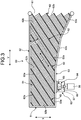
- FIG. 3 is a plan view of the positioning station for the mobile body according to the present embodiment
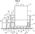
- FIG. 4 is a schematic diagram illustrating the mobile body positioned at the positioning station.
- a power feeding station 50 includes a first partition 51, a second partition 52, a third partition 53, and a guide device (the guide) 54.
- an entrance port 61 through which the robot 10 enters is defined by the second partition 52 continuously provided from one end of the first partition 51 and the third partition 53 continuously provided from the other end of the first partition 51. That is, an extending direction (an X direction) of the first partition 51 intersects (is perpendicular to) both an extending direction (a Y direction) of the second partition 52 and an extending direction (a Y direction) of the third partition 53; and the extending direction (the Y direction) of the second partition 52 and the extending direction (the Y direction) of the third partition 53 are parallel to each other.
- the entrance port 61 is defined between an end portion of the second partition 52 in the extending direction and an end portion of the third partition 53 in the extending direction.
- the third partition 53 includes a straight portion 53a, a first oblique portion 53b, and a second oblique portion 53c, so that the entrance port 61 has a widened shape.
- the guide device 54 is disposed in a region surrounded by the first partition 51, the second partition 52, and the third partition 53.
- the first partition 51 is disposed along the X direction perpendicular to a Y direction that is an entering direction of the robot 10 to the power feeding station 50, and the first partition 51 has a length slightly longer than a width of the robot 10.
- the second partition 52 is disposed along the Y direction that is the entering direction of the robot 10 to the power feeding station 50, and the second partition 52 has a length two times or more longer than a length of the robot 10.
- first partition 51 After the positioning of the robot 10 in the Y direction is performed by the first partition 51, and when the robot 10 moves toward the second partition 52, one side portion of the robot 10 comes into contact with the second partition 52 to position the robot 10 with respect to the X direction.
- the lengths of the first partition 51 and the second partition 52 are not limited to those in the present embodiment but may be made longer or shorter than those in the present embodiment.
- the third partition 53 is disposed along the Y direction that is the entering direction of the robot 10 to the power feeding station 50, and the third partition 53 has a length two times or more longer than the length of the robot 10.
- the third partition 53 guides and makes the robot 10 move toward the first partition 51.
- the second partition 52 and the third partition 53 are parallel to each other.
- the first partition 51 and the second partition 52 make a right angle
- the first partition 51 and the third partition 53 make a right angle. Consequently, the power feeding station 50 has a U shape formed by the first partition 51, the second partition 52, and the third partition 53 in plan view.
- the end portion of the second partition 52 and the end portion of the third partition 53 define the entrance port 61 through which the robot 10 enters.
- a distance between the second partition 52 and the third partition 53 is set at a length slightly longer than the width of the robot 10.
- the straight portion 53a, the first oblique portion 53b, and the second oblique portion 53c that constitute the third partition 53 make the entrance port 61 have the widened shape gradually increasing in width. That is, distances between the second partition 52 and the oblique portions 53b, 53c of the third partition 53 increase from the first partition 51 toward the entrance port 61.
- the guide device 54 guides the robot 10 along an A direction (hereinafter referred to as an oblique direction A) obliquely extending from the first partition 51 side toward the second partition 52 side.
- the oblique direction A is at a predetermined acute angle ⁇ set in advance with respect to the Y direction along the second partition 52.
- the predetermined acute angle ⁇ is in an angle range larger than 0 degree and smaller than 90 degrees (0 degrees ⁇ ⁇ ⁇ 90 degrees)
- an angle range equal to or larger than 15 degrees and smaller than 90 degrees (15 degrees ⁇ ⁇ ⁇ 90 degrees) is preferable
- an angle range equal to or larger than 30 degrees and equal to or smaller than 60 degrees (30 degrees ⁇ ⁇ ⁇ 60 degrees) is optimal.
- the guide device 54 includes a plurality of guide rollers 62 horizontally disposed on a floor surface G in the region surrounded by the first partition 51, the second partition 52, and the third partition 53.
- the floor surface G is horizontal.
- the guide rollers 62 are preferably disposed horizontally, the guide rollers 62 may be disposed at an inclined angle with respect to horizontality.
- the guide rollers 62 are disposed along the direction inclined at the acute angle ⁇ with respect to the Y direction along the second partition 52. That is, the guide rollers 62 includes a plurality of roller main bodies 62b rotatably supported between a pair of support plates 62a.
- These guide rollers 62 have rotary center axes extending along a direction that intersects (is perpendicular to) the oblique direction A, and the guide rollers 62 are parallel to one another along the oblique direction A.
- a plurality of sets of the guide rollers 62 are disposed along the direction perpendicular to the oblique direction A.
- the guide rollers 62 are disposed along the oblique direction A in such a manner that rotary center axes of the roller main bodies 62b are parallel to one another.
- the power feeding station 50 includes a power feeding device 63 and an air replenishment device 64 that are disposed on the third partition 53.
- the power feeding device 63 includes a power feeder 65 and a mover 66 to move the power feeder 65.
- the air replenishment device 64 includes an air replenisher 67 and a mover 68 to move the air replenisher 67.
- the power feeding device 63 can couple the power feeder 65 to the power feeding coupler 41 of the robot 10 through a cut-away portion 53d of the straight portion 53a of the third partition 53.
- the air replenishment device 64 can couple the air replenisher 67 to the air replenishment coupler 42 of the robot 10 through the cut-away portion 53d of the third partition 53.
- the power feeding system (the positioning system) according to the present embodiment includes the robot 10 and the power feeding station 50 described above. Operation of the power feeding system according to the present embodiment will now be described.
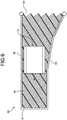
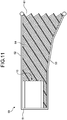
- FIG. 5 to FIG. 11 are schematic diagrams illustrating positioning behaviors of the mobile body at the positioning station.
- FIG. 12 is a schematic diagram illustrating a positioned state of the mobile body at the positioning station.
- the control device 14 controls the movement device 12 based on map information and distance information so that the robot 10 moves in the petrochemical plant to perform patrol work.
- the control device 14 controls the movement device 12 so that the robot 10 moves to the power feeding station 50 to replenish power and air.
- the control device 14 may monitor the charged amount of the battery 13 and the air amount of the air tank 26, and when the charged amount and the air amount become equal to or smaller than preset lower limits, the robot 10 may move to the power feeding station 50.
- the robot 10 enters the power feeding station 50 through the entrance port 61 while moving rearward.
- the robot 10 may enter the power feeding station 50 while moving forward depending on positions of the power feeding coupler 41 and the air replenishment coupler 42.
- the robot 10 enters between the second partition 52 and the straight portion 53a of the third partition 53.
- the robot 10 is occasionally deviated toward the third partition 53 upon entrance due to a control error. Such an entrance mode of the robot 10 will be described below.
- the rear portion of the robot 10 comes into contact with the first partition 51 and becomes unable to move rearward any more.
- the movement device 12 rotates the left and right crawlers 23 so that rotational force of the left and right crawlers 23 causes the guide rollers 62 of the guide device 54 to rotate.
- the left and right crawlers 23 of the robot 10 rotates while being directed to one side of the Y direction, whereas the guide rollers 62 rotate while facing one side of the oblique direction A.
- the robot 10 is guided and moved in the one side of the oblique direction A with rotation of the guide rollers 62.
- the guide rollers 62 of the guide device 54 rotate to guide the robot 10 toward the one side of the oblique direction A. Since the left and right crawlers 23 rotate, moving force of the robot 10 in the other side of the Y directions is cancelled, and the robot 10 moves in one side of the X direction. That is, as illustrated in FIG. 11 , with the rear end portion of the robot 10 being in contact with the first partition 51, the robot 10 moves in the one side of the X direction, and one side portion of the robot 10 comes into contact with the second partition 52. In other words, even after the rear portion of the robot 10 comes into contact with the first partition 51, the robot 10 continues rearward movement, namely, movement (rotation of the crawlers 23) to move (travel) in the Y direction.
- the guide rollers 62 are rotated by the rearward movement of the robot 10 so that the guide device 54 causes the robot 10 to move along the first partition 51 toward the second partition 52.
- the detector 43 is disposed at the rear portion of the robot 10.
- the detector 43 detects that the first contact portion 44 has come into contact with the first partition 51 and outputs a detection result to the control device 14.
- the control device 14 stops the movement device 12. Consequently, after the first contact portion 44 comes into contact with the first partition 51 and disables the robot 10 from moving rearward, rotation of the guide rollers 62 of the guide device 54 causes the robot 10 to move toward the second partition 52, and after the second contact portion 45 comes into contact with the second partition 52, the left and right crawlers 23 stop moving, thereby completing the positioning of the robot 10.
- the power feeding device 63 performs power feeding work with respect to the battery 13
- the air replenishment device 64 performs air replenishment work with respect to the air tank 26.
- the robot 10 is not deviated even when the mover 66 presses and couples the power feeder 65 to the power feeding coupler 41 of the robot 10 and even when the mover 68 presses and couples the air replenisher 67 to the air replenishment coupler 42 of the robot 10.
- the power feeding device 63 and the air replenishment device 64 are decoupled from the robot 10, and the movement device 12 causes the robot 10 to move forward and exit the power feeding station 50.
- the mobile body positioning station includes the first partition 51, the second partition 52 disposed along the direction intersecting the extending direction of the first partition 51, and the guide device (the guide) 54 disposed on the movement path of the robot (the mobile body) 10.
- the guide device 54 is disposed along the oblique direction A with respect to the direction perpendicular to the extending direction of the first partition 51 to extend from the first partition 51 toward the second partition side 52.
- the guide device 54 is configured to make the robot 10 move in the oblique direction A more easily than move in directions other than the oblique direction A.
- the guide device 54 is configured to move the robot 10 along the first partition 51 toward the second partition 52.
- the robot 10 stops moving and the positioning in the Y direction is performed.
- the guide device 54 guides the robot 10 toward the second partition 52 along the oblique direction in which the robot 10 moves easily. Then, when one side portion of the robot 10 comes into contact with the second partition 52, the guide device 54 stops guiding the robot 10, and the positioning of the robot 10 in the X direction and the Y direction is completed. Thus, no sensor to detect the robot 10 is needed so that the configuration can be simplified.
- the guide device 54 causes the robot 10 to move along the first partition 51 toward the second partition 52 after the robot 10 comes into contact with the first partition 51. Consequently, the robot 10 can be positioned highly accurately.
- the guide device 54 is configured to cause the robot 10 to move toward the second partition 52 with use of movement driving force of the robot 10. Consequently, the movement driving force of the robot 10 can make the guide device 54 function to efficiently move and guide the robot 10 toward the second partition 52.
- the oblique direction A is the direction inclined at the predetermined acute angle ⁇ set in advance with respect to the Y direction (first direction) along the second partition 52. Consequently, the movement driving force of the robot 10 can be transmitted to the guide device 54 to efficiently guide the robot 10 toward the second partition 52 and position the robot 10.
- the oblique direction A is set in a range equal to or larger than 15 degrees and smaller than 90 degrees. Consequently, setting of the oblique direction A in the appropriate range makes it possible to position the robot 10 appropriately.
- the extending direction of the first partition 51 and the extending direction of the second partition 52 are arranged to make a right angle. Consequently, the robot 10 that has come into contact with the first partition 51 can be appropriately positioned with respect to the Y direction, and also, the robot 10 that has come into contact with the second partition 52 can be appropriately positioned with respect to the X direction and the Y direction.
- the guide rollers 62 are provided as the guide device 54.
- the guide rollers 62 are disposed along the oblique direction A.
- the rotary center axes of the guide rollers 62 extend along the direction intersecting the oblique direction A, and the guide rollers 62 are disposed in parallel to one another. Consequently, the movement driving force of the robot 10 makes the guide rollers 62 rotate so that the rotational force of the guide rollers 62 can efficiently cause the robot 10 to move and be guided toward the second partition 52.
- the third partition 53 is disposed opposite to the second partition 52 and extends along the direction intersecting the extending direction of the first partition 51, and the entrance port 61 of the robot 10 is defined between the end portion of the second partition 52 in the extending direction and the end portion of the third partition 53 in the extending direction.
- the distance between the second partition 52 and the third partition 53 increases from the first partition 51 toward the entrance port 61. Consequently, even when an entrance position of the robot 10 with respect to the entrance port 61 is deviated in the width direction, the entrance port 61 of the widened shape can appropriately guide the robot 10 inside.
- An end portion of the guide device 54 may have a slope, for example, as the entrance port 61, thus facilitating entrance and exit of the mobile body.
- the power feeding device 63 for the robot 10 is disposed on the third partition 53. Consequently, with respect to the robot 10 that has come into contact with the first partition 51 and the second partition 52 and been positioned, power feeding is performed from the third partition 53 opposed to the second partition 52 so that the robot 10 can be prevented from being deviated due to coupling of the power feeding device 63, thereby appropriately performing power feeding.
- the air replenishment device 64 for the robot 10 is disposed on the third partition 53. Consequently, with respect to the robot 10 that has come into contact with the first partition 51 and the second partition 52 and been positioned, air replenishment is performed from the third partition 53 opposed to the second partition 52 so that the robot 10 can be prevented from being deviated due to coupling of the air replenishment device 64, thereby appropriately performing power feeding.
- the mobile body positioning system includes the control device 14 to control movement of the robot 10 capable of being self-propelled, and the power feeding station 50 for the robot 10.
- the control device 14 stops movement of the robot 10 when the predetermined period of time has elapsed after the robot 10 came into contact with the first partition 51.
- the guide device 54 guides the robot 10 toward the second partition 52 along the oblique direction in which the robot 10 moves easily, and the robot 10 comes into contact with the second partition 52 so that the positioning in the X direction and the Y direction is performed.
- the robot 10 stops moving when the predetermined period of time has elapsed after the robot 10 came into contact with the first partition 51 so that the robot 10 can be positioned at an appropriate position.
- the guide according to the present invention has a configuration that makes the mobile body move in the oblique direction more easily than move in directions other than the oblique direction.
- the guide according to the present invention includes the guide rollers 62 but is not limited to this configuration.
- a sheet including a guide having low friction resistance only along the oblique direction from the first partition toward the second partition may be disposed on the movement path. That is, as illustrated in FIG. 3 , this sheet has the guide a surface of which has the lowest friction resistance in the oblique direction A from the first partition 51 toward the second partition 52.
- the guide according to the present invention is the guide device 54 driven by the movement driving force of the robot 10 but is not limited to this configuration.
- the guide may have a function to cause the robot 10 to move in the oblique direction in which the guide moves easily.
- the first partition 51, the second partition 52, and the third partition 53 are continuous surfaces in the X direction and the Y direction but are not limited to this configuration.
- the first partition 51, the second partition 52, and the third partition 53 are not made continuous but may have gaps therebetween.
- the first partition 51, the second partition 52, and the third partition 53 may be composed of a plurality of columns disposed at a predetermined interval in the X direction and the Y direction.
- the first partition 51 and the second partition 52 may be provided whereas the third partition 53 may be eliminated.
- the robot 10 as the mobile body includes the first contact portion 44 and the second contact portion 45, where the robot 10 comes into contact with the first partition 51 and the second partition 52.
- the frame 11 of the robot 10 may directly come into contact with the first partition 51 and the second partition 52.
- the robot 10 as the mobile body is self-propelled when the onboard control device 14 controls the movement device 12.
- the robot 10 as the mobile body may be self-propelled by remotely controlling the movement device 12.
- the positioning station positions the robot 10 as the mobile body for the purposes of feeding power and replenishing air to the robot 10.
- positioning may be performed, for example, to load and unload packages in and from the mobile body.
- the mobile body positioning station and the mobile body positioning system according to the present invention are applied to patrol inspection work in the petrochemical plant but may be applied to nuclear power plants, pharmaceutical plants, steel plants, various kinds of manufacturing plants, and other facilities, and may be also applied to work, such as disaster prevention and relief work and building maintenance work.
Landscapes
- Engineering & Computer Science (AREA)
- Mechanical Engineering (AREA)
- Power Engineering (AREA)
- Transportation (AREA)
- Remote Sensing (AREA)
- Radar, Positioning & Navigation (AREA)
- Aviation & Aerospace Engineering (AREA)
- Physics & Mathematics (AREA)
- General Physics & Mathematics (AREA)
- Automation & Control Theory (AREA)
- Control Of Position, Course, Altitude, Or Attitude Of Moving Bodies (AREA)
- Manipulator (AREA)
- Charge And Discharge Circuits For Batteries Or The Like (AREA)
- Electric Propulsion And Braking For Vehicles (AREA)
Abstract
Description
- The present invention relates to a mobile body positioning station and a mobile body positioning system that positions a movable mobile body at a predetermined position to perform various kinds of work.
- In patrol inspection work or the like using a movable robot, the robot needs to perform various kinds of work, such as refueling and maintenance work. In this case, when performing patrol inspection work or the like, the robot is self-propelled to a station to perform these various kinds of work. When the patrol inspection work is performed in, for example, a petrochemical plant, if a substance such as petroleum leaks, the work environment of the robot will become an explosive atmosphere to cause a fire upon ignition with sparks generated at actuation of the robot. Consequently, in this case, the robot needs to have an explosion-proof structure.
- For example, an explosion-proof structure of a conventional robot is described in Patent Literature 1 below. An industrial robot described in Patent Literature 1 includes a control device, a battery, and a motor that are disposed on a movable frame, and has an internal pressure explosion-proof structure in which air is supplied into the frame from an air supply device so as to maintain the inside the frame at a pressure higher than a predetermined pressure.
- Patent Literature 1:
JP 2015-036172 A - When the movable robot as described above is self-propelled to a station and performs various kinds of work, there is need to position the robot at a predetermined position. In this case, it is conceivable to provide a detection sensor in the robot or station and control and determine a position of the robot based on the detection result obtained by the detection sensor. However, this may unfortunately complicate configurations of the robot or station.
- The present invention has been made to solve the above-described problem, and an object of the present invention is to provide a mobile body positioning station and a mobile body positioning system that have simplified configurations.
- To achieve the object described above, a mobile body positioning station according to the present invention includes a first partition; a second partition disposed along a direction intersecting an extending direction of the first partition; and a guide disposed on a movement path of a mobile body. The guide is disposed along an oblique direction with respect to a direction perpendicular to the extending direction of the first partition to extend from the first partition toward the second partition side. The guide is configured to make the mobile body move in the oblique direction more easily than move in directions other than the oblique direction, and the guide is configured to move the mobile body along the first partition toward the second partition.
- Consequently, when the mobile body moves and a front end in a moving direction comes into contact with the first partition, the mobile body stops moving and the positioning at the front is done. Then, the guide guides the mobile body toward the second partition along the oblique direction in which the mobile body moves easily. When one side of the mobile body comes into contact with the second partition, the guide stops guiding the mobile body, and the positioning at the one side of the mobile body is done. Thus, no sensor to detect the mobile body is needed so that the configuration can be simplified.
- In the mobile body positioning station according to the present invention, the guide is configured to cause the mobile body to move along the first partition toward the second partition after the mobile body comes into contact with the first partition.
- Consequently, after the mobile body comes into contact with the first partition, the guide causes the mobile body to move toward the second partition so that the mobile body can be positioned with the simple configuration.
- In the mobile body positioning station according to the present invention, the guide is configured to cause the mobile body to move toward the second partition with use of movement driving force of the mobile body.
- Consequently, the movement driving force of the mobile body can make the guide function to efficiently move and guide the mobile body toward the second partition.
- In the mobile body positioning station according to the present invention, the oblique direction is a direction inclined at a predetermined acute angle set in advance with respect to an extending direction of the second partition.
- Consequently, the oblique direction is the direction inclined at the predetermined acute angle with respect to the extending direction of the second partition so that the movement driving force of the mobile body can be transmitted to the guide to efficiently guide the mobile body toward the second partition and position the mobile body.
- In the mobile body positioning station according to the present invention, the oblique direction is set in a range equal to or larger than 15 degrees and smaller than 90 degrees.
- Consequently, setting of the oblique direction in the appropriate range makes it possible to position the mobile body appropriately.
- In the mobile body positioning station according to the present invention, the first partition and the second partition are disposed in such a manner that the extending direction of the first partition and an extending direction of the second partition make a right angle.
- Consequently, the first partition and the second partition are disposed to make a right angle so that the mobile body that has come into contact with the first partition can be appropriately positioned, and that the mobile body that has come into contact with the second partition can be appropriately positioned.
- In the mobile body positioning station according to the present invention, the guide comprises a plurality of guide rollers disposed along the oblique direction, rotary center axes of the guide rollers extend along a direction intersecting the oblique direction, and the guide rollers are disposed in parallel to one another.
- Consequently, the guide rollers are provided as the guide, and the guide rollers are disposed along the oblique direction and in parallel to one another so that rotational force of the guide rollers can efficiently move and guide the mobile body toward the second partition.
- In the mobile body positioning station according to the present invention, the guide includes a plurality of guide rollers. The guide rollers includes: a pair of support plates; and at least one roller main body. The pair of support plates is disposed along the oblique direction. The at least one of roller main bodies is rotatably disposed by a rotary shaft perpendicular to the support plates.
- Consequently, the rotational force of the guide rollers can efficiently move and guide the mobile body toward the second partition.
- The mobile body positioning station according to the present invention further includes: a third partition facing the second partition and disposed along a direction intersecting the extending direction of the first partition; and an entrance port of the mobile body defined between an end portion of the second partition in the extending direction and an end portion of the third partition in the extending direction. A distance between the second partition and the third partition increases from the first partition toward the entrance port.
- Consequently, the entrance port is defined between the end portion of the second partition and the end portion of the third partition, and the distance between the second partition and the third partition increases from the first partition toward the entrance port. Thus, even when an entrance position of the mobile body with respect to the entrance port is deviated in a width direction, the entrance port can appropriately guide the mobile body inside.
- The mobile body positioning station according to the present invention further includes a power feeding device for the mobile body disposed on the third partition.
- Consequently, with the power feeding device being disposed on the third partition, power feeding with respect to the mobile body that has come into contact with the first partition and the second partition and been positioned is performed from the third partition opposed to the second partition, so that the mobile body can be prevented from being deviated due to coupling of the power feeding device, thereby appropriately performing power feeding.
- The mobile body positioning station according to the present invention further includes an air replenishment device for the mobile body disposed on the third partition.
- Consequently, with the air replenishment device being disposed on the third partition, air replenishment with respect to the mobile body that has come into contact with the first partition and the second partition and been positioned is performed from the third partition opposed to the second partition so that the mobile body can be prevented from being deviated due to coupling of the air replenishment device, thereby appropriately performing air replenishment.
- A mobile body positioning system according to the present invention includes: a control device configured to control movement of the mobile body capable of being self-propelled; and the mobile body positioning station described above. The control device stops movement of the mobile body when a predetermined period of time has elapsed after the mobile body comes into contact with the first partition.
- Consequently, after the moving mobile body comes into contact with the first partition and the positioning at the front is done, the guide guides the mobile body toward the second partition along the oblique direction in which the mobile body moves easily, and the mobile body comes into contact with the second partition so that the positioning at one side is done. At this time, the mobile body stops moving when the predetermined period of time has elapsed after the mobile body came into contact with the first partition so that the mobile body can be positioned at an appropriate position.
- The mobile body positioning station and the mobile body positioning system according to the present invention can simplify the configurations.
-
-
FIG. 1 is a schematic side view of a mobile body according to the embodiment. -
FIG. 2 is a schematic plan view of the mobile body. -
FIG. 3 is a plan view of a positioning station for the mobile body according to the embodiment. -
FIG. 4 is a schematic diagram illustrating the mobile body positioned at the positioning station. -
FIG. 5 is a schematic diagram illustrating positioning behaviors of the mobile body at the positioning station. -
FIG. 6 is a schematic diagram illustrating a positioning behavior of the mobile body at the positioning station. -
FIG. 7 is a schematic diagram illustrating a positioning behavior of the mobile body at the positioning station. -
FIG. 8 is a schematic diagram illustrating a positioning behavior of the mobile body at the positioning station. -
FIG. 9 is a schematic diagram illustrating a positioning behavior of the mobile body at the positioning station. -
FIG. 10 is a schematic diagram illustrating a positioning behavior of the mobile body at the positioning station. -
FIG. 11 is a schematic diagram illustrating a positioning behavior of the mobile body at the positioning station. -
FIG. 12 is a schematic diagram illustrating a positioned state of the mobile body at the positioning station. - Hereinafter, a preferred embodiment of a mobile body positioning station and a mobile body positioning system according to the present invention will be described in detail with reference to the accompanying drawings. The invention is not limited by the present embodiment, and that when there are a plurality of embodiments, the invention encompasses a combination of the embodiments.
- In an equipment to perform patrol inspection work by a mobile body moving in a petrochemical plant, for example, the mobile body positioning station and the mobile body positioning system according to the present embodiment position the mobile body at a predetermined position for an operation such as feeding power to the mobile body. If petroleum or the like leaks in the petrochemical plant, a work environment of the mobile body becomes an explosive atmosphere. Therefore, the mobile body has an explosion-proof structure.
- First, a robot as the mobile body will be described.
FIG. 1 is a schematic side view of the mobile body according to the embodiment, andFIG. 2 is a schematic plan view of the mobile body. - In the present embodiment, as illustrated in
FIG. 1 andFIG. 2 , a robot (the mobile body) 10 includes aframe 11, amovement device 12, abattery 13, acontrol device 14, an internal pressure explosion-proof device 15, acamera 16, and acommunication device 17. It is noted that inFIG. 1 , a right side is a front side of the robot, and that rightward movement is forward movement whereas leftward movement is rearward movement. - The
frame 11 has a hollow box shape and a sealing structure. Themovement device 12 is disposed under theframe 11 so that theframe 11 can move solely. Themovement device 12 includes anelectric motor 21, drivesprockets 22, andcrawlers 23. Theelectric motor 21 is mounted in theframe 11. The drive sprockets 22 are attached to front and rear lower portions of theframe 11 on both sides, and thecrawlers 23 are wound on the front andrear drive sprockets 22 on the left and the right. Themovement device 12 is not limited to the fourdrive sprockets 22 and thecrawlers 23 but may include a plurality of drive wheels instead. - The
battery 13 and thecontrol device 14 are mounted in theframe 11. Thebattery 13 is capable of supplying power to thecontrol device 14 and theelectric motor 21. Thecontrol device 14 drivingly controls theelectric motor 21 so that forward movement, rearward movement and stopping of theframe 11, i.e., therobot 10, can be controlled using themovement device 12. - The internal pressure explosion-
proof device 15 maintains pressure inside theframe 11 higher than pressure outside theframe 11 so as to prevent external gas from entering the inside of theframe 11. The internal pressure explosion-proof device 15 includes anair supplier 24 and anexhaust device 25. Theair supplier 24 includes anair tank 26 disposed outside of theframe 11, and an air supply line 28 extending from theair tank 26 to the inside of theframe 11 through theframe 11. The air supply line 28 includes apressure reducing valve 29 outside of theframe 11 and has an end portion opened. Thus, normally, pressurized air of theair tank 26 is supplied to the inside of theframe 11 through the air supply line 28, and thepressure reducing valve 29 maintains the internal pressure of theframe 11 at a constant set pressure higher than the external pressure of theframe 11. - The
exhaust device 25 includes anair discharge line 31 penetrating theframe 11 and extending to the inside. Theair discharge line 31 includes arelief valve 32 outside of theframe 11 and has an end portion opened. Therefore, when the temperature inside theframe 11 rises and the pressure inside theframe 11 becomes higher than the set pressure, therelief valve 32 causes air inside theframe 11 to be discharged to the outside through theair discharge line 31, thus decreasing the pressure inside theframe 11. - The
camera 16 is mounted at an upper portion of the inside of theframe 11. Under control of thecontrol device 14, thecamera 16 is capable of capturing an outside image and outputs the captured image to thecontrol device 14. Thecommunication device 17 is capable of communicating with an external management room (not illustrated), for example. Thecommunication device 17 sends thecontrol device 14 information input from the outside, and also sends the outside information from thecontrol device 14 such as the image captured by thecamera 16. - The
robot 10 includes apower feeding coupler 41 and anair replenishment coupler 42 that are disposed on theframe 11. Thepower feeding coupler 41 and theair replenishment coupler 42 are disposed on one side portion of theframe 11 along a vertical direction. Thepower feeding coupler 41 is coupled to thebattery 13, and theair replenishment coupler 42 is coupled to theair tank 26. - The
robot 10 includes adetector 43 at a rear end portion of the inside of theframe 11. A cover that covers thedetector 43 from the outside functions as afirst contact portion 44. During rearward movement of therobot 10, thedetector 43 detects that thefirst contact portion 44 comes into contact with an obstacle and inputs a detection result to thecontrol device 14. Therobot 10 further includes asecond contact portion 45 disposed on the other side portion of theframe 11. - The
robot 10 includes an onboard protection monitoring device (not illustrated) to stop power supply from thebattery 13 to the movement device (electric motor 21) 12, thecontrol device 14, thecamera 16, and thecommunication device 17 when the pressure inside theframe 11 becomes equal to or lower than the predetermined air pressure (a pressure at least higher than an atmospheric pressure) set in advance. Moreover, although not illustrated, therobot 10 may be equipped with a robot arm, for example. - The
robot 10 configured as described above is capable of forward movement, rearward movement, and stopping through the control of themovement device 12 by thecontrol device 14. Therobot 10 can be steered by adjusting the speeds of the right and left crawlers 23 through the control ofmovement device 12 by thecontrol device 14. In therobot 10, thecontrol device 14 stores a patrol map and determines a moving route based on this map information and distance information detected by a sensor mounted on therobot 10. Therobot 10 may determine a moving route in accordance with positional signals from the GPS. - The
robot 10 needs to be subjected to power supply when the charged amount of thebattery 13 has decreased through patrol inspection work or the like; and therobot 10 needs air replenishment when an amount of air (air pressure) in theair tank 26 has decreased. Therefore, in the present embodiment, a power feeding station (the positioning station) is disposed in a patrol inspection work zone. - Next, the power feeding station (the positioning station) will be described.
FIG. 3 is a plan view of the positioning station for the mobile body according to the present embodiment, andFIG. 4 is a schematic diagram illustrating the mobile body positioned at the positioning station. - In the present embodiment, as illustrated in
FIG. 3 andFIG. 4 , apower feeding station 50 includes afirst partition 51, asecond partition 52, athird partition 53, and a guide device (the guide) 54. - In the
power feeding station 50, anentrance port 61 through which therobot 10 enters is defined by thesecond partition 52 continuously provided from one end of thefirst partition 51 and thethird partition 53 continuously provided from the other end of thefirst partition 51. That is, an extending direction (an X direction) of thefirst partition 51 intersects (is perpendicular to) both an extending direction (a Y direction) of thesecond partition 52 and an extending direction (a Y direction) of thethird partition 53; and the extending direction (the Y direction) of thesecond partition 52 and the extending direction (the Y direction) of thethird partition 53 are parallel to each other. Theentrance port 61 is defined between an end portion of thesecond partition 52 in the extending direction and an end portion of thethird partition 53 in the extending direction. Thethird partition 53 includes astraight portion 53a, afirst oblique portion 53b, and asecond oblique portion 53c, so that theentrance port 61 has a widened shape. Theguide device 54 is disposed in a region surrounded by thefirst partition 51, thesecond partition 52, and thethird partition 53. - The
first partition 51 is disposed along the X direction perpendicular to a Y direction that is an entering direction of therobot 10 to thepower feeding station 50, and thefirst partition 51 has a length slightly longer than a width of therobot 10. When therobot 10 moves rearward and enters thepower feeding station 50, a rear end portion of therobot 10 comes into contact with thefirst partition 51 to position therobot 10 with respect to the Y direction. Thesecond partition 52 is disposed along the Y direction that is the entering direction of therobot 10 to thepower feeding station 50, and thesecond partition 52 has a length two times or more longer than a length of therobot 10. After the positioning of therobot 10 in the Y direction is performed by thefirst partition 51, and when therobot 10 moves toward thesecond partition 52, one side portion of therobot 10 comes into contact with thesecond partition 52 to position therobot 10 with respect to the X direction. The lengths of thefirst partition 51 and thesecond partition 52 are not limited to those in the present embodiment but may be made longer or shorter than those in the present embodiment. - The
third partition 53 is disposed along the Y direction that is the entering direction of therobot 10 to thepower feeding station 50, and thethird partition 53 has a length two times or more longer than the length of therobot 10. When therobot 10 enters thepower feeding station 50, thethird partition 53 guides and makes therobot 10 move toward thefirst partition 51. Thesecond partition 52 and thethird partition 53 are parallel to each other. Thefirst partition 51 and thesecond partition 52 make a right angle, and thefirst partition 51 and thethird partition 53 make a right angle. Consequently, thepower feeding station 50 has a U shape formed by thefirst partition 51, thesecond partition 52, and thethird partition 53 in plan view. The end portion of thesecond partition 52 and the end portion of thethird partition 53 define theentrance port 61 through which therobot 10 enters. In this case, a distance between thesecond partition 52 and thethird partition 53 is set at a length slightly longer than the width of therobot 10. Thestraight portion 53a, thefirst oblique portion 53b, and thesecond oblique portion 53c that constitute thethird partition 53 make theentrance port 61 have the widened shape gradually increasing in width. That is, distances between thesecond partition 52 and theoblique portions third partition 53 increase from thefirst partition 51 toward theentrance port 61. - Using movement driving force of the
robot 10, theguide device 54 guides therobot 10 along an A direction (hereinafter referred to as an oblique direction A) obliquely extending from thefirst partition 51 side toward thesecond partition 52 side. The oblique direction A is at a predetermined acute angle θ set in advance with respect to the Y direction along thesecond partition 52. Although the predetermined acute angle θ is in an angle range larger than 0 degree and smaller than 90 degrees (0 degrees < θ < 90 degrees), an angle range equal to or larger than 15 degrees and smaller than 90 degrees (15 degrees ≤ θ < 90 degrees) is preferable, and an angle range equal to or larger than 30 degrees and equal to or smaller than 60 degrees (30 degrees ≤ θ ≤ 60 degrees) is optimal. Theguide device 54 includes a plurality ofguide rollers 62 horizontally disposed on a floor surface G in the region surrounded by thefirst partition 51, thesecond partition 52, and thethird partition 53. In this case, the floor surface G is horizontal. Although theguide rollers 62 are preferably disposed horizontally, theguide rollers 62 may be disposed at an inclined angle with respect to horizontality. Theguide rollers 62 are disposed along the direction inclined at the acute angle θ with respect to the Y direction along thesecond partition 52. That is, theguide rollers 62 includes a plurality of rollermain bodies 62b rotatably supported between a pair ofsupport plates 62a. These guiderollers 62 have rotary center axes extending along a direction that intersects (is perpendicular to) the oblique direction A, and theguide rollers 62 are parallel to one another along the oblique direction A. A plurality of sets of theguide rollers 62 are disposed along the direction perpendicular to the oblique direction A. In other words, theguide rollers 62 are disposed along the oblique direction A in such a manner that rotary center axes of the rollermain bodies 62b are parallel to one another. - The
power feeding station 50 includes apower feeding device 63 and anair replenishment device 64 that are disposed on thethird partition 53. Thepower feeding device 63 includes apower feeder 65 and amover 66 to move thepower feeder 65. Theair replenishment device 64 includes anair replenisher 67 and amover 68 to move theair replenisher 67. Thepower feeding device 63 can couple thepower feeder 65 to thepower feeding coupler 41 of therobot 10 through a cut-awayportion 53d of thestraight portion 53a of thethird partition 53. Similarly, theair replenishment device 64 can couple theair replenisher 67 to theair replenishment coupler 42 of therobot 10 through the cut-awayportion 53d of thethird partition 53. - The power feeding system (the positioning system) according to the present embodiment includes the
robot 10 and thepower feeding station 50 described above. Operation of the power feeding system according to the present embodiment will now be described.FIG. 5 to FIG. 11 are schematic diagrams illustrating positioning behaviors of the mobile body at the positioning station.FIG. 12 is a schematic diagram illustrating a positioned state of the mobile body at the positioning station. - As illustrated in
FIG. 1 , thecontrol device 14 controls themovement device 12 based on map information and distance information so that therobot 10 moves in the petrochemical plant to perform patrol work. When the charged amount of thebattery 13 and the air amount (air pressure) of theair tank 26 decrease, thecontrol device 14 controls themovement device 12 so that therobot 10 moves to thepower feeding station 50 to replenish power and air. In this case, thecontrol device 14 may monitor the charged amount of thebattery 13 and the air amount of theair tank 26, and when the charged amount and the air amount become equal to or smaller than preset lower limits, therobot 10 may move to thepower feeding station 50. - As illustrated in
FIG. 1 andFIG. 5 , therobot 10 enters thepower feeding station 50 through theentrance port 61 while moving rearward. Alternatively, therobot 10 may enter thepower feeding station 50 while moving forward depending on positions of thepower feeding coupler 41 and theair replenishment coupler 42. At this time, as indicated by the dash-dot-dot lines inFIG. 5 , it is preferable that therobot 10 enters between thesecond partition 52 and thestraight portion 53a of thethird partition 53. However, as indicated by the solid lines inFIG. 5 , therobot 10 is occasionally deviated toward thethird partition 53 upon entrance due to a control error. Such an entrance mode of therobot 10 will be described below. - When the
robot 10 is deviated toward thethird partition 53 upon entrance as indicated by the solid lines inFIG. 5 , one end of a rear portion of therobot 10 in a width direction first comes into contact with thesecond oblique portion 53c of thethird partition 53 as illustrated inFIG. 6 , and therobot 10 turns clockwise along thesecond oblique portion 53c. Consequently, as illustrated inFIG. 7 , therobot 10 is corrected to a direction along thesecond oblique portion 53c and moves as it is. Next, as illustrated inFIG. 8 , the other end of the rear portion of therobot 10 in the width direction comes into contact with thesecond partition 52, and therobot 10 turns counterclockwise along thesecond partition 52. Thus, as illustrated inFIG. 9 , therobot 10 is corrected to a direction along thesecond partition 52 and moves as it is. - Then, as illustrated in
FIG. 10 , the rear portion of therobot 10 comes into contact with thefirst partition 51 and becomes unable to move rearward any more. At this time, although therobot 10 is unable to move rearward, themovement device 12 rotates the left andright crawlers 23 so that rotational force of the left andright crawlers 23 causes theguide rollers 62 of theguide device 54 to rotate. Then, the left andright crawlers 23 of therobot 10 rotates while being directed to one side of the Y direction, whereas theguide rollers 62 rotate while facing one side of the oblique direction A. Thus, therobot 10 is guided and moved in the one side of the oblique direction A with rotation of theguide rollers 62. In this case, theguide rollers 62 of theguide device 54 rotate to guide therobot 10 toward the one side of the oblique direction A. Since the left andright crawlers 23 rotate, moving force of therobot 10 in the other side of the Y directions is cancelled, and therobot 10 moves in one side of the X direction. That is, as illustrated inFIG. 11 , with the rear end portion of therobot 10 being in contact with thefirst partition 51, therobot 10 moves in the one side of the X direction, and one side portion of therobot 10 comes into contact with thesecond partition 52. In other words, even after the rear portion of therobot 10 comes into contact with thefirst partition 51, therobot 10 continues rearward movement, namely, movement (rotation of the crawlers 23) to move (travel) in the Y direction. It may be regarded that in the rearward movement of therobot 10 after the rear portion of therobot 10 comes into contact with thefirst partition 51, theguide rollers 62 are rotated by the rearward movement of therobot 10 so that theguide device 54 causes therobot 10 to move along thefirst partition 51 toward thesecond partition 52. - At this time, as illustrated in
FIG. 2 , thedetector 43 is disposed at the rear portion of therobot 10. Thedetector 43 detects that thefirst contact portion 44 has come into contact with thefirst partition 51 and outputs a detection result to thecontrol device 14. When a predetermined period of time has elapsed after thefirst contact portion 44 came into contact with thefirst partition 51, thecontrol device 14 stops themovement device 12. Consequently, after thefirst contact portion 44 comes into contact with thefirst partition 51 and disables therobot 10 from moving rearward, rotation of theguide rollers 62 of theguide device 54 causes therobot 10 to move toward thesecond partition 52, and after thesecond contact portion 45 comes into contact with thesecond partition 52, the left andright crawlers 23 stop moving, thereby completing the positioning of therobot 10. - Thereafter, as illustrated in
FIG. 4 andFIG. 12 , with therobot 10 being in contact with thefirst partition 51 and thesecond partition 52 and positioned, thepower feeding device 63 performs power feeding work with respect to thebattery 13, and theair replenishment device 64 performs air replenishment work with respect to theair tank 26. At this time, because therobot 10 is in contact with thesecond partition 52, therobot 10 is not deviated even when themover 66 presses and couples thepower feeder 65 to thepower feeding coupler 41 of therobot 10 and even when themover 68 presses and couples theair replenisher 67 to theair replenishment coupler 42 of therobot 10. - When the power feeding work and the air replenishment work for the
robot 10 are completed, thepower feeding device 63 and theair replenishment device 64 are decoupled from therobot 10, and themovement device 12 causes therobot 10 to move forward and exit thepower feeding station 50. - As described above, the mobile body positioning station according to the present embodiment includes the
first partition 51, thesecond partition 52 disposed along the direction intersecting the extending direction of thefirst partition 51, and the guide device (the guide) 54 disposed on the movement path of the robot (the mobile body) 10. Theguide device 54 is disposed along the oblique direction A with respect to the direction perpendicular to the extending direction of thefirst partition 51 to extend from thefirst partition 51 toward thesecond partition side 52. Theguide device 54 is configured to make therobot 10 move in the oblique direction A more easily than move in directions other than the oblique direction A. Theguide device 54 is configured to move therobot 10 along thefirst partition 51 toward thesecond partition 52. - Consequently, when the
robot 10 moves and the rear end portion comes into contact with thefirst partition 51, therobot 10 stops moving and the positioning in the Y direction is performed. Theguide device 54 guides therobot 10 toward thesecond partition 52 along the oblique direction in which therobot 10 moves easily. Then, when one side portion of therobot 10 comes into contact with thesecond partition 52, theguide device 54 stops guiding therobot 10, and the positioning of therobot 10 in the X direction and the Y direction is completed. Thus, no sensor to detect therobot 10 is needed so that the configuration can be simplified. - In the mobile body positioning station according to the present embodiment, the
guide device 54 causes therobot 10 to move along thefirst partition 51 toward thesecond partition 52 after therobot 10 comes into contact with thefirst partition 51. Consequently, therobot 10 can be positioned highly accurately. - In the mobile body positioning station according to the present embodiment, the
guide device 54 is configured to cause therobot 10 to move toward thesecond partition 52 with use of movement driving force of therobot 10. Consequently, the movement driving force of therobot 10 can make theguide device 54 function to efficiently move and guide therobot 10 toward thesecond partition 52. - In the mobile body positioning station according to the present embodiment, the oblique direction A is the direction inclined at the predetermined acute angle θ set in advance with respect to the Y direction (first direction) along the
second partition 52. Consequently, the movement driving force of therobot 10 can be transmitted to theguide device 54 to efficiently guide therobot 10 toward thesecond partition 52 and position therobot 10. - In the mobile body positioning station according to the present embodiment, the oblique direction A is set in a range equal to or larger than 15 degrees and smaller than 90 degrees. Consequently, setting of the oblique direction A in the appropriate range makes it possible to position the
robot 10 appropriately. - In the mobile body positioning station according to the present embodiment, the extending direction of the
first partition 51 and the extending direction of thesecond partition 52 are arranged to make a right angle. Consequently, therobot 10 that has come into contact with thefirst partition 51 can be appropriately positioned with respect to the Y direction, and also, therobot 10 that has come into contact with thesecond partition 52 can be appropriately positioned with respect to the X direction and the Y direction. - In the mobile body positioning station according to the present embodiment, the
guide rollers 62 are provided as theguide device 54. Theguide rollers 62 are disposed along the oblique direction A. The rotary center axes of theguide rollers 62 extend along the direction intersecting the oblique direction A, and theguide rollers 62 are disposed in parallel to one another. Consequently, the movement driving force of therobot 10 makes theguide rollers 62 rotate so that the rotational force of theguide rollers 62 can efficiently cause therobot 10 to move and be guided toward thesecond partition 52. - In the mobile body positioning station according to the present embodiment, the
third partition 53 is disposed opposite to thesecond partition 52 and extends along the direction intersecting the extending direction of thefirst partition 51, and theentrance port 61 of therobot 10 is defined between the end portion of thesecond partition 52 in the extending direction and the end portion of thethird partition 53 in the extending direction. The distance between thesecond partition 52 and thethird partition 53 increases from thefirst partition 51 toward theentrance port 61. Consequently, even when an entrance position of therobot 10 with respect to theentrance port 61 is deviated in the width direction, theentrance port 61 of the widened shape can appropriately guide therobot 10 inside. An end portion of theguide device 54 may have a slope, for example, as theentrance port 61, thus facilitating entrance and exit of the mobile body. - In the mobile body positioning station according to the present embodiment, the
power feeding device 63 for therobot 10 is disposed on thethird partition 53. Consequently, with respect to therobot 10 that has come into contact with thefirst partition 51 and thesecond partition 52 and been positioned, power feeding is performed from thethird partition 53 opposed to thesecond partition 52 so that therobot 10 can be prevented from being deviated due to coupling of thepower feeding device 63, thereby appropriately performing power feeding. - In the mobile body positioning station according to the present embodiment, the
air replenishment device 64 for therobot 10 is disposed on thethird partition 53. Consequently, with respect to therobot 10 that has come into contact with thefirst partition 51 and thesecond partition 52 and been positioned, air replenishment is performed from thethird partition 53 opposed to thesecond partition 52 so that therobot 10 can be prevented from being deviated due to coupling of theair replenishment device 64, thereby appropriately performing power feeding. - The mobile body positioning system according to the present embodiment includes the
control device 14 to control movement of therobot 10 capable of being self-propelled, and thepower feeding station 50 for therobot 10. Thecontrol device 14 stops movement of therobot 10 when the predetermined period of time has elapsed after therobot 10 came into contact with thefirst partition 51. - Consequently, after the moving
robot 10 comes into contact with thefirst partition 51 and the positioning in the Y direction is performed, theguide device 54 guides therobot 10 toward thesecond partition 52 along the oblique direction in which therobot 10 moves easily, and therobot 10 comes into contact with thesecond partition 52 so that the positioning in the X direction and the Y direction is performed. At this time, therobot 10 stops moving when the predetermined period of time has elapsed after therobot 10 came into contact with thefirst partition 51 so that therobot 10 can be positioned at an appropriate position. - It is noted that the guide according to the present invention has a configuration that makes the mobile body move in the oblique direction more easily than move in directions other than the oblique direction. In the above-described embodiment, the guide according to the present invention includes the
guide rollers 62 but is not limited to this configuration. For example, a sheet including a guide having low friction resistance only along the oblique direction from the first partition toward the second partition may be disposed on the movement path. That is, as illustrated inFIG. 3 , this sheet has the guide a surface of which has the lowest friction resistance in the oblique direction A from thefirst partition 51 toward thesecond partition 52. In the oblique direction A from thesecond partition 52 toward thefirst partition 51 and in a direction intersecting the oblique direction A, surface friction resistance is higher than in the oblique direction A from thefirst partition 51 toward thesecond partition 52. When the sheet including the guide that has been subjected to such surface treatment is employed, the mobile body can be appropriately guided and positioned. - In the above-described embodiment, the guide according to the present invention is the
guide device 54 driven by the movement driving force of therobot 10 but is not limited to this configuration. The guide may have a function to cause therobot 10 to move in the oblique direction in which the guide moves easily. - In the above-described embodiment, the
first partition 51, thesecond partition 52, and thethird partition 53 are continuous surfaces in the X direction and the Y direction but are not limited to this configuration. For example, thefirst partition 51, thesecond partition 52, and thethird partition 53 are not made continuous but may have gaps therebetween. Alternatively, thefirst partition 51, thesecond partition 52, and thethird partition 53 may be composed of a plurality of columns disposed at a predetermined interval in the X direction and the Y direction. Alternatively, thefirst partition 51 and thesecond partition 52 may be provided whereas thethird partition 53 may be eliminated. Therobot 10 as the mobile body includes thefirst contact portion 44 and thesecond contact portion 45, where therobot 10 comes into contact with thefirst partition 51 and thesecond partition 52. However, theframe 11 of therobot 10 may directly come into contact with thefirst partition 51 and thesecond partition 52. - In the above-described embodiment, the
robot 10 as the mobile body is self-propelled when theonboard control device 14 controls themovement device 12. However, therobot 10 as the mobile body may be self-propelled by remotely controlling themovement device 12. - In the above-described embodiment, the positioning station according to the present invention positions the
robot 10 as the mobile body for the purposes of feeding power and replenishing air to therobot 10. However, instead of such work, positioning may be performed, for example, to load and unload packages in and from the mobile body. - In the above-described embodiment, the mobile body positioning station and the mobile body positioning system according to the present invention are applied to patrol inspection work in the petrochemical plant but may be applied to nuclear power plants, pharmaceutical plants, steel plants, various kinds of manufacturing plants, and other facilities, and may be also applied to work, such as disaster prevention and relief work and building maintenance work.
-
- 10
- robot (mobile body)
- 11
- frame
- 12
- movement device
- 13
- battery
- 14
- control device
- 15
- internal pressure explosion-proof device
- 16
- camera
- 17
- communication device
- 21
- electric motor
- 22
- drive sprocket
- 23
- crawler
- 24
- air supplier
- 25
- exhaust device
- 26
- air tank
- 28
- air supply line
- 29
- pressure reducing valve
- 32
- relief valve
- 31
- air discharge line
- 41
- power feeding coupler
- 42
- air replenishment coupler
- 43
- detector
- 44
- first contact portion
- 45
- second contact portion
- 50
- power feeding station (positioning station)
- 51
- first partition
- 52
- second partition
- 53
- third partition
- 54
- guide device (guide)
- 61
- entrance port
- 62
- guide roller
- 63
- power feeding device
- 64
- air replenishment device
- 65
- power feeder
- 66, 68
- mover
- 67
- air replenisher
Claims (12)
- A mobile body positioning station comprising:a first partition;a second partition disposed along a direction intersecting an extending direction of the first partition; anda guide disposed on a movement path of a mobile body, whereinthe guide is disposed along an oblique direction with respect to a direction perpendicular to the extending direction of the first partition to extend from the first partition toward the second partition side, andthe guide is configured to make the mobile body move in the oblique direction more easily than move in directions other than the oblique direction, and the guide is configured to move the mobile body along the first partition toward the second partition.
- The mobile body positioning station according to claim 1, wherein the guide is configured to cause the mobile body to move along the first partition toward the second partition after the mobile body comes into contact with the first partition.
- The mobile body positioning station according to claim 1 or 2, wherein the guide is configured to cause the mobile body to move toward the second partition with use of movement driving force of the mobile body.
- The mobile body positioning station according to any one of claims 1 to 3, wherein the oblique direction is a direction inclined at a predetermined acute angle set in advance with respect to an extending direction of the second partition.
- The mobile body positioning station according to any one of claims 1 to 4, wherein the oblique direction is set in a range equal to or larger than 15 degrees and smaller than 90 degrees.
- The mobile body positioning station according to any one of claims 1 to 5, wherein the first partition and the second partition are disposed in such a manner that the extending direction of the first partition and an extending direction of the second partition make a right angle.
- The mobile body positioning station according to any one of claims 1 to 6, wherein
the guide comprises a plurality of guide rollers disposed along the oblique direction,
rotary center axes of the guide rollers extend along a direction intersecting the oblique direction, and
the guide rollers are disposed in parallel to one another. - The mobile body positioning station according to any one of claims 1 to 7, wherein
the guide comprises a plurality of guide rollers,
the guide rollers comprise:a pair of support plates; andat least one roller main body,the pair of support plates is disposed along the oblique direction, and
the at least one of roller main bodies is rotatably disposed by a rotary shaft perpendicular to the support plates. - The mobile body positioning station according to any one of claims 1 to 8, further comprising:a third partition facing the second partition and disposed along a direction intersecting the extending direction of the first partition; andan entrance port of the mobile body defined between an end portion of the second partition in the extending direction and an end portion of the third partition in the extending direction, whereina distance between the second partition and the third partition increases from the first partition toward the entrance port.
- The mobile body positioning station according to claim 9, further comprising a power feeding device for the mobile body disposed on the third partition.
- The mobile body positioning station according to claim 9 or 10, further comprising an air replenishment device for the mobile body disposed on the third partition.
- A mobile body positioning system comprising:a control device configured to control movement of the mobile body capable of being self-propelled; andthe mobile body positioning station according to any one of claims 1 to 11, whereinthe control device stops movement of the mobile body when a predetermined period of time has elapsed after the mobile body comes into contact with the first partition.
Applications Claiming Priority (2)
| Application Number | Priority Date | Filing Date | Title |
|---|---|---|---|
| JP2018109057A JP7051596B2 (en) | 2018-06-06 | 2018-06-06 | Moving body positioning station and moving body positioning system |
| PCT/JP2019/007392 WO2019235000A1 (en) | 2018-06-06 | 2019-02-26 | Moving body positioning station and moving body positioning system |
Publications (3)
| Publication Number | Publication Date |
|---|---|
| EP3806269A1 true EP3806269A1 (en) | 2021-04-14 |
| EP3806269A4 EP3806269A4 (en) | 2021-08-18 |
| EP3806269B1 EP3806269B1 (en) | 2024-03-20 |
Family
ID=68770384
Family Applications (1)
| Application Number | Title | Priority Date | Filing Date |
|---|---|---|---|
| EP19815170.6A Active EP3806269B1 (en) | 2018-06-06 | 2019-02-26 | Moving body positioning station and moving body positioning system |
Country Status (4)
| Country | Link |
|---|---|
| US (1) | US12084292B2 (en) |
| EP (1) | EP3806269B1 (en) |
| JP (1) | JP7051596B2 (en) |
| WO (1) | WO2019235000A1 (en) |
Families Citing this family (1)
| Publication number | Priority date | Publication date | Assignee | Title |
|---|---|---|---|---|
| JP7611183B2 (en) * | 2022-03-16 | 2025-01-09 | 三菱重工業株式会社 | Information processing device, mobility control system, information processing method and program |
Family Cites Families (12)
| Publication number | Priority date | Publication date | Assignee | Title |
|---|---|---|---|---|
| US2128594A (en) * | 1935-05-24 | 1938-08-30 | Robert P Rasmussen | Conveyer |
| EP0125331A1 (en) | 1983-05-16 | 1984-11-21 | The Boeing Company | Apparatus and method for sheet metal part alignment |
| JPH104638A (en) * | 1996-06-13 | 1998-01-06 | Sumitomo Wiring Syst Ltd | Charger for electric vehicle |
| JP3516343B1 (en) | 2002-06-20 | 2004-04-05 | 旭精機工業株式会社 | Transfer device and transfer system |
| US7040478B2 (en) * | 2003-08-05 | 2006-05-09 | Rapistan Systems Advertising Corp. | Steerable diverter system |
| US7249671B2 (en) * | 2005-05-06 | 2007-07-31 | Laitram, L.L.C. | Roller-belt conveyor for accumulating and moving articles laterally across the conveyor |
| US7861847B2 (en) * | 2009-05-28 | 2011-01-04 | Laitram, L.L.C. | Roller-belt depalletizer |
| JP5582074B2 (en) | 2011-03-11 | 2014-09-03 | トヨタ自動車株式会社 | Vehicle, automatic parking support equipment and automatic parking system |
| JP2013230084A (en) | 2013-06-24 | 2013-11-07 | Ntt Facilities Inc | Storage cart charging device |
| JP6307230B2 (en) | 2013-08-13 | 2018-04-04 | 三菱重工業株式会社 | Industrial robot |
| US10162350B2 (en) | 2014-09-10 | 2018-12-25 | Universal City Studios Llc | Systems and methods for controlling the transportation of vehicles |
| WO2020072613A1 (en) * | 2018-10-03 | 2020-04-09 | Material Handling Systems, Inc. | Singulating system for parcels |
-
2018
- 2018-06-06 JP JP2018109057A patent/JP7051596B2/en active Active
-
2019
- 2019-02-26 US US15/734,049 patent/US12084292B2/en active Active
- 2019-02-26 WO PCT/JP2019/007392 patent/WO2019235000A1/en not_active Ceased
- 2019-02-26 EP EP19815170.6A patent/EP3806269B1/en active Active
Also Published As
| Publication number | Publication date |
|---|---|
| EP3806269B1 (en) | 2024-03-20 |
| JP7051596B2 (en) | 2022-04-11 |
| JP2019213384A (en) | 2019-12-12 |
| WO2019235000A1 (en) | 2019-12-12 |
| US20210216078A1 (en) | 2021-07-15 |
| US12084292B2 (en) | 2024-09-10 |
| EP3806269A4 (en) | 2021-08-18 |
Similar Documents
| Publication | Publication Date | Title |
|---|---|---|
| CN112218807B (en) | Service vehicle and method for extinguishing fires on and inside an automated access system | |
| US8807234B2 (en) | Automated storage system | |
| EP3670389B1 (en) | Overhead transport vehicle, overhead transport system, and control method for overhead transport vehicle | |
| JP6454676B2 (en) | Piping inspection robot | |
| US20160272472A1 (en) | Wireless vehicle lift system with enhanced electronic controls | |
| KR102337930B1 (en) | Robot for monitoring passage type structure | |
| EP3806269B1 (en) | Moving body positioning station and moving body positioning system | |
| JP4089154B2 (en) | Travel control method for moving body | |
| RU2755461C1 (en) | Self-propelled fire extinguishing complex based on self-propelled robot | |
| CN101631712A (en) | Steering system and method for train of wheeled vehicles | |
| KR102615038B1 (en) | Cantilever type stacker crane system | |
| JP5427561B2 (en) | Robot system with transfer function | |
| CN213491656U (en) | A battery pack flame retardant device and system | |
| KR20210059372A (en) | Smart home device ceiling transfer system | |
| CN117163184A (en) | A back-up jacking AGV system for cab sub-assembly line | |
| CN112349442B (en) | A remote control fire control operation system and a remote control fire control operation method | |
| KR20210052998A (en) | Traveling device for bottom step adjustment and movable upward pretreatment blasting equipment comprising the same | |
| KR102788519B1 (en) | Radio-controlled automatic welding device for ships | |
| KR102320778B1 (en) | Gas detection robot | |
| CN215701764U (en) | A factory inspection robot and its management system | |
| JPH07146707A (en) | Remote control method for heavy equipment vehicles | |
| KR102656907B1 (en) | System for installing floor finishing materials | |
| CN219056448U (en) | AGV mobile robot platform | |
| JP2003326368A (en) | Flash welding equipment | |
| CN119329398A (en) | Radiation-resistant AGV for radioactive environments |
Legal Events
| Date | Code | Title | Description |
|---|---|---|---|
| STAA | Information on the status of an ep patent application or granted ep patent |
Free format text: STATUS: THE INTERNATIONAL PUBLICATION HAS BEEN MADE |
|
| PUAI | Public reference made under article 153(3) epc to a published international application that has entered the european phase |
Free format text: ORIGINAL CODE: 0009012 |
|
| STAA | Information on the status of an ep patent application or granted ep patent |
Free format text: STATUS: REQUEST FOR EXAMINATION WAS MADE |
|
| 17P | Request for examination filed |
Effective date: 20201229 |
|
| AK | Designated contracting states |
Kind code of ref document: A1 Designated state(s): AL AT BE BG CH CY CZ DE DK EE ES FI FR GB GR HR HU IE IS IT LI LT LU LV MC MK MT NL NO PL PT RO RS SE SI SK SM TR |
|
| AX | Request for extension of the european patent |
Extension state: BA ME |
|
| REG | Reference to a national code |
Ref country code: DE Ref legal event code: R079 Free format text: PREVIOUS MAIN CLASS: H02J0007000000 Ipc: G05D0001020000 Ref country code: DE Ref legal event code: R079 Ref document number: 602019048715 Country of ref document: DE Free format text: PREVIOUS MAIN CLASS: H02J0007000000 Ipc: G05D0001020000 |
|
| A4 | Supplementary search report drawn up and despatched |
Effective date: 20210719 |
|
| RIC1 | Information provided on ipc code assigned before grant |
Ipc: G05D 1/02 20200101AFI20210713BHEP Ipc: H02J 7/00 20060101ALI20210713BHEP Ipc: B25J 5/00 20060101ALI20210713BHEP Ipc: B60L 15/20 20060101ALI20210713BHEP |
|
| DAV | Request for validation of the european patent (deleted) | ||
| DAX | Request for extension of the european patent (deleted) | ||
| STAA | Information on the status of an ep patent application or granted ep patent |
Free format text: STATUS: EXAMINATION IS IN PROGRESS |
|
| 17Q | First examination report despatched |
Effective date: 20220824 |
|
| GRAP | Despatch of communication of intention to grant a patent |
Free format text: ORIGINAL CODE: EPIDOSNIGR1 |
|
| STAA | Information on the status of an ep patent application or granted ep patent |
Free format text: STATUS: GRANT OF PATENT IS INTENDED |
|
| INTG | Intention to grant announced |
Effective date: 20231017 |
|
| P01 | Opt-out of the competence of the unified patent court (upc) registered |
Effective date: 20231120 |
|
| GRAS | Grant fee paid |
Free format text: ORIGINAL CODE: EPIDOSNIGR3 |
|
| GRAA | (expected) grant |
Free format text: ORIGINAL CODE: 0009210 |
|
| STAA | Information on the status of an ep patent application or granted ep patent |
Free format text: STATUS: THE PATENT HAS BEEN GRANTED |
|
| AK | Designated contracting states |
Kind code of ref document: B1 Designated state(s): AL AT BE BG CH CY CZ DE DK EE ES FI FR GB GR HR HU IE IS IT LI LT LU LV MC MK MT NL NO PL PT RO RS SE SI SK SM TR |
|
| REG | Reference to a national code |
Ref country code: GB Ref legal event code: FG4D |
|
| REG | Reference to a national code |
Ref country code: CH Ref legal event code: EP |
|
| REG | Reference to a national code |
Ref country code: IE Ref legal event code: FG4D |
|
| REG | Reference to a national code |
Ref country code: DE Ref legal event code: R096 Ref document number: 602019048715 Country of ref document: DE |
|
| PG25 | Lapsed in a contracting state [announced via postgrant information from national office to epo] |
Ref country code: LT Free format text: LAPSE BECAUSE OF FAILURE TO SUBMIT A TRANSLATION OF THE DESCRIPTION OR TO PAY THE FEE WITHIN THE PRESCRIBED TIME-LIMIT Effective date: 20240320 |
|
| REG | Reference to a national code |
Ref country code: LT Ref legal event code: MG9D |
|
| PG25 | Lapsed in a contracting state [announced via postgrant information from national office to epo] |
Ref country code: GR Free format text: LAPSE BECAUSE OF FAILURE TO SUBMIT A TRANSLATION OF THE DESCRIPTION OR TO PAY THE FEE WITHIN THE PRESCRIBED TIME-LIMIT Effective date: 20240621 |
|
| PG25 | Lapsed in a contracting state [announced via postgrant information from national office to epo] |
Ref country code: HR Free format text: LAPSE BECAUSE OF FAILURE TO SUBMIT A TRANSLATION OF THE DESCRIPTION OR TO PAY THE FEE WITHIN THE PRESCRIBED TIME-LIMIT Effective date: 20240320 Ref country code: RS Free format text: LAPSE BECAUSE OF FAILURE TO SUBMIT A TRANSLATION OF THE DESCRIPTION OR TO PAY THE FEE WITHIN THE PRESCRIBED TIME-LIMIT Effective date: 20240620 |
|
| REG | Reference to a national code |
Ref country code: NL Ref legal event code: MP Effective date: 20240320 |
|
| PG25 | Lapsed in a contracting state [announced via postgrant information from national office to epo] |
Ref country code: RS Free format text: LAPSE BECAUSE OF FAILURE TO SUBMIT A TRANSLATION OF THE DESCRIPTION OR TO PAY THE FEE WITHIN THE PRESCRIBED TIME-LIMIT Effective date: 20240620 Ref country code: NO Free format text: LAPSE BECAUSE OF FAILURE TO SUBMIT A TRANSLATION OF THE DESCRIPTION OR TO PAY THE FEE WITHIN THE PRESCRIBED TIME-LIMIT Effective date: 20240620 Ref country code: LT Free format text: LAPSE BECAUSE OF FAILURE TO SUBMIT A TRANSLATION OF THE DESCRIPTION OR TO PAY THE FEE WITHIN THE PRESCRIBED TIME-LIMIT Effective date: 20240320 Ref country code: HR Free format text: LAPSE BECAUSE OF FAILURE TO SUBMIT A TRANSLATION OF THE DESCRIPTION OR TO PAY THE FEE WITHIN THE PRESCRIBED TIME-LIMIT Effective date: 20240320 Ref country code: GR Free format text: LAPSE BECAUSE OF FAILURE TO SUBMIT A TRANSLATION OF THE DESCRIPTION OR TO PAY THE FEE WITHIN THE PRESCRIBED TIME-LIMIT Effective date: 20240621 Ref country code: FI Free format text: LAPSE BECAUSE OF FAILURE TO SUBMIT A TRANSLATION OF THE DESCRIPTION OR TO PAY THE FEE WITHIN THE PRESCRIBED TIME-LIMIT Effective date: 20240320 Ref country code: BG Free format text: LAPSE BECAUSE OF FAILURE TO SUBMIT A TRANSLATION OF THE DESCRIPTION OR TO PAY THE FEE WITHIN THE PRESCRIBED TIME-LIMIT Effective date: 20240320 |
|
| REG | Reference to a national code |
Ref country code: AT Ref legal event code: MK05 Ref document number: 1668394 Country of ref document: AT Kind code of ref document: T Effective date: 20240320 |
|
| PG25 | Lapsed in a contracting state [announced via postgrant information from national office to epo] |
Ref country code: SE Free format text: LAPSE BECAUSE OF FAILURE TO SUBMIT A TRANSLATION OF THE DESCRIPTION OR TO PAY THE FEE WITHIN THE PRESCRIBED TIME-LIMIT Effective date: 20240320 Ref country code: LV Free format text: LAPSE BECAUSE OF FAILURE TO SUBMIT A TRANSLATION OF THE DESCRIPTION OR TO PAY THE FEE WITHIN THE PRESCRIBED TIME-LIMIT Effective date: 20240320 |
|
| PG25 | Lapsed in a contracting state [announced via postgrant information from national office to epo] |
Ref country code: NL Free format text: LAPSE BECAUSE OF FAILURE TO SUBMIT A TRANSLATION OF THE DESCRIPTION OR TO PAY THE FEE WITHIN THE PRESCRIBED TIME-LIMIT Effective date: 20240320 |
|
| PG25 | Lapsed in a contracting state [announced via postgrant information from national office to epo] |
Ref country code: NL Free format text: LAPSE BECAUSE OF FAILURE TO SUBMIT A TRANSLATION OF THE DESCRIPTION OR TO PAY THE FEE WITHIN THE PRESCRIBED TIME-LIMIT Effective date: 20240320 |
|
| PG25 | Lapsed in a contracting state [announced via postgrant information from national office to epo] |
Ref country code: IS Free format text: LAPSE BECAUSE OF FAILURE TO SUBMIT A TRANSLATION OF THE DESCRIPTION OR TO PAY THE FEE WITHIN THE PRESCRIBED TIME-LIMIT Effective date: 20240720 |
|
| PG25 | Lapsed in a contracting state [announced via postgrant information from national office to epo] |
Ref country code: PT Free format text: LAPSE BECAUSE OF FAILURE TO SUBMIT A TRANSLATION OF THE DESCRIPTION OR TO PAY THE FEE WITHIN THE PRESCRIBED TIME-LIMIT Effective date: 20240722 Ref country code: SM Free format text: LAPSE BECAUSE OF FAILURE TO SUBMIT A TRANSLATION OF THE DESCRIPTION OR TO PAY THE FEE WITHIN THE PRESCRIBED TIME-LIMIT Effective date: 20240320 |
|
| PG25 | Lapsed in a contracting state [announced via postgrant information from national office to epo] |
Ref country code: ES Free format text: LAPSE BECAUSE OF FAILURE TO SUBMIT A TRANSLATION OF THE DESCRIPTION OR TO PAY THE FEE WITHIN THE PRESCRIBED TIME-LIMIT Effective date: 20240320 |
|
| PG25 | Lapsed in a contracting state [announced via postgrant information from national office to epo] |
Ref country code: CZ Free format text: LAPSE BECAUSE OF FAILURE TO SUBMIT A TRANSLATION OF THE DESCRIPTION OR TO PAY THE FEE WITHIN THE PRESCRIBED TIME-LIMIT Effective date: 20240320 Ref country code: EE Free format text: LAPSE BECAUSE OF FAILURE TO SUBMIT A TRANSLATION OF THE DESCRIPTION OR TO PAY THE FEE WITHIN THE PRESCRIBED TIME-LIMIT Effective date: 20240320 |
|
| PG25 | Lapsed in a contracting state [announced via postgrant information from national office to epo] |
Ref country code: AT Free format text: LAPSE BECAUSE OF FAILURE TO SUBMIT A TRANSLATION OF THE DESCRIPTION OR TO PAY THE FEE WITHIN THE PRESCRIBED TIME-LIMIT Effective date: 20240320 |
|
| PG25 | Lapsed in a contracting state [announced via postgrant information from national office to epo] |
Ref country code: PL Free format text: LAPSE BECAUSE OF FAILURE TO SUBMIT A TRANSLATION OF THE DESCRIPTION OR TO PAY THE FEE WITHIN THE PRESCRIBED TIME-LIMIT Effective date: 20240320 |
|
| PG25 | Lapsed in a contracting state [announced via postgrant information from national office to epo] |
Ref country code: SK Free format text: LAPSE BECAUSE OF FAILURE TO SUBMIT A TRANSLATION OF THE DESCRIPTION OR TO PAY THE FEE WITHIN THE PRESCRIBED TIME-LIMIT Effective date: 20240320 |
|
| PG25 | Lapsed in a contracting state [announced via postgrant information from national office to epo] |
Ref country code: SM Free format text: LAPSE BECAUSE OF FAILURE TO SUBMIT A TRANSLATION OF THE DESCRIPTION OR TO PAY THE FEE WITHIN THE PRESCRIBED TIME-LIMIT Effective date: 20240320 Ref country code: SK Free format text: LAPSE BECAUSE OF FAILURE TO SUBMIT A TRANSLATION OF THE DESCRIPTION OR TO PAY THE FEE WITHIN THE PRESCRIBED TIME-LIMIT Effective date: 20240320 Ref country code: RO Free format text: LAPSE BECAUSE OF FAILURE TO SUBMIT A TRANSLATION OF THE DESCRIPTION OR TO PAY THE FEE WITHIN THE PRESCRIBED TIME-LIMIT Effective date: 20240320 Ref country code: PT Free format text: LAPSE BECAUSE OF FAILURE TO SUBMIT A TRANSLATION OF THE DESCRIPTION OR TO PAY THE FEE WITHIN THE PRESCRIBED TIME-LIMIT Effective date: 20240722 Ref country code: PL Free format text: LAPSE BECAUSE OF FAILURE TO SUBMIT A TRANSLATION OF THE DESCRIPTION OR TO PAY THE FEE WITHIN THE PRESCRIBED TIME-LIMIT Effective date: 20240320 Ref country code: IS Free format text: LAPSE BECAUSE OF FAILURE TO SUBMIT A TRANSLATION OF THE DESCRIPTION OR TO PAY THE FEE WITHIN THE PRESCRIBED TIME-LIMIT Effective date: 20240720 Ref country code: ES Free format text: LAPSE BECAUSE OF FAILURE TO SUBMIT A TRANSLATION OF THE DESCRIPTION OR TO PAY THE FEE WITHIN THE PRESCRIBED TIME-LIMIT Effective date: 20240320 Ref country code: EE Free format text: LAPSE BECAUSE OF FAILURE TO SUBMIT A TRANSLATION OF THE DESCRIPTION OR TO PAY THE FEE WITHIN THE PRESCRIBED TIME-LIMIT Effective date: 20240320 Ref country code: CZ Free format text: LAPSE BECAUSE OF FAILURE TO SUBMIT A TRANSLATION OF THE DESCRIPTION OR TO PAY THE FEE WITHIN THE PRESCRIBED TIME-LIMIT Effective date: 20240320 Ref country code: AT Free format text: LAPSE BECAUSE OF FAILURE TO SUBMIT A TRANSLATION OF THE DESCRIPTION OR TO PAY THE FEE WITHIN THE PRESCRIBED TIME-LIMIT Effective date: 20240320 |
|
| PG25 | Lapsed in a contracting state [announced via postgrant information from national office to epo] |
Ref country code: IT Free format text: LAPSE BECAUSE OF FAILURE TO SUBMIT A TRANSLATION OF THE DESCRIPTION OR TO PAY THE FEE WITHIN THE PRESCRIBED TIME-LIMIT Effective date: 20240320 |
|
| REG | Reference to a national code |
Ref country code: DE Ref legal event code: R097 Ref document number: 602019048715 Country of ref document: DE |
|
| PG25 | Lapsed in a contracting state [announced via postgrant information from national office to epo] |
Ref country code: IT Free format text: LAPSE BECAUSE OF FAILURE TO SUBMIT A TRANSLATION OF THE DESCRIPTION OR TO PAY THE FEE WITHIN THE PRESCRIBED TIME-LIMIT Effective date: 20240320 |
|
| PG25 | Lapsed in a contracting state [announced via postgrant information from national office to epo] |
Ref country code: DK Free format text: LAPSE BECAUSE OF FAILURE TO SUBMIT A TRANSLATION OF THE DESCRIPTION OR TO PAY THE FEE WITHIN THE PRESCRIBED TIME-LIMIT Effective date: 20240320 |
|
| PLBE | No opposition filed within time limit |
Free format text: ORIGINAL CODE: 0009261 |
|
| STAA | Information on the status of an ep patent application or granted ep patent |
Free format text: STATUS: NO OPPOSITION FILED WITHIN TIME LIMIT |
|
| PG25 | Lapsed in a contracting state [announced via postgrant information from national office to epo] |
Ref country code: DK Free format text: LAPSE BECAUSE OF FAILURE TO SUBMIT A TRANSLATION OF THE DESCRIPTION OR TO PAY THE FEE WITHIN THE PRESCRIBED TIME-LIMIT Effective date: 20240320 |
|
| 26N | No opposition filed |
Effective date: 20241223 |
|
| PG25 | Lapsed in a contracting state [announced via postgrant information from national office to epo] |
Ref country code: SI Free format text: LAPSE BECAUSE OF FAILURE TO SUBMIT A TRANSLATION OF THE DESCRIPTION OR TO PAY THE FEE WITHIN THE PRESCRIBED TIME-LIMIT Effective date: 20240320 |
|
| REG | Reference to a national code |
Ref country code: DE Ref legal event code: R119 Ref document number: 602019048715 Country of ref document: DE |
|
| PG25 | Lapsed in a contracting state [announced via postgrant information from national office to epo] |
Ref country code: MC Free format text: LAPSE BECAUSE OF FAILURE TO SUBMIT A TRANSLATION OF THE DESCRIPTION OR TO PAY THE FEE WITHIN THE PRESCRIBED TIME-LIMIT Effective date: 20240320 |
|
| REG | Reference to a national code |
Ref country code: CH Ref legal event code: PL |
|
| PG25 | Lapsed in a contracting state [announced via postgrant information from national office to epo] |
Ref country code: LU Free format text: LAPSE BECAUSE OF NON-PAYMENT OF DUE FEES Effective date: 20250226 |
|
| PG25 | Lapsed in a contracting state [announced via postgrant information from national office to epo] |
Ref country code: CH Free format text: LAPSE BECAUSE OF NON-PAYMENT OF DUE FEES Effective date: 20250228 |
|
| GBPC | Gb: european patent ceased through non-payment of renewal fee |
Effective date: 20250226 |
|
| REG | Reference to a national code |
Ref country code: BE Ref legal event code: MM Effective date: 20250228 |
|
| PG25 | Lapsed in a contracting state [announced via postgrant information from national office to epo] |
Ref country code: DE Free format text: LAPSE BECAUSE OF NON-PAYMENT OF DUE FEES Effective date: 20250902 |
|
| PG25 | Lapsed in a contracting state [announced via postgrant information from national office to epo] |
Ref country code: GB Free format text: LAPSE BECAUSE OF NON-PAYMENT OF DUE FEES Effective date: 20250226 |
|
| PGFP | Annual fee paid to national office [announced via postgrant information from national office to epo] |
Ref country code: FR Payment date: 20251231 Year of fee payment: 8 |
|
| PG25 | Lapsed in a contracting state [announced via postgrant information from national office to epo] |
Ref country code: BE Free format text: LAPSE BECAUSE OF NON-PAYMENT OF DUE FEES Effective date: 20250228 |
|
| PG25 | Lapsed in a contracting state [announced via postgrant information from national office to epo] |
Ref country code: IE Free format text: LAPSE BECAUSE OF NON-PAYMENT OF DUE FEES Effective date: 20250226 |