EP3806057A1 - Heat sensor - Google Patents
Heat sensor Download PDFInfo
- Publication number
- EP3806057A1 EP3806057A1 EP19811068.6A EP19811068A EP3806057A1 EP 3806057 A1 EP3806057 A1 EP 3806057A1 EP 19811068 A EP19811068 A EP 19811068A EP 3806057 A1 EP3806057 A1 EP 3806057A1
- Authority
- EP
- European Patent Office
- Prior art keywords
- heat
- housing
- heat sensor
- holes
- central axis
- Prior art date
- Legal status (The legal status is an assumption and is not a legal conclusion. Google has not performed a legal analysis and makes no representation as to the accuracy of the status listed.)
- Granted
Links
Images








Classifications
-
- G—PHYSICS
- G01—MEASURING; TESTING
- G01K—MEASURING TEMPERATURE; MEASURING QUANTITY OF HEAT; THERMALLY-SENSITIVE ELEMENTS NOT OTHERWISE PROVIDED FOR
- G01K13/00—Thermometers specially adapted for specific purposes
- G01K13/02—Thermometers specially adapted for specific purposes for measuring temperature of moving fluids or granular materials capable of flow
- G01K13/024—Thermometers specially adapted for specific purposes for measuring temperature of moving fluids or granular materials capable of flow of moving gases
-
- G—PHYSICS
- G01—MEASURING; TESTING
- G01K—MEASURING TEMPERATURE; MEASURING QUANTITY OF HEAT; THERMALLY-SENSITIVE ELEMENTS NOT OTHERWISE PROVIDED FOR
- G01K3/00—Thermometers giving results other than momentary value of temperature
- G01K3/005—Circuits arrangements for indicating a predetermined temperature
-
- G—PHYSICS
- G08—SIGNALLING
- G08B—SIGNALLING SYSTEMS, e.g. PERSONAL CALLING SYSTEMS; ORDER TELEGRAPHS; ALARM SYSTEMS
- G08B17/00—Fire alarms; Alarms responsive to explosion
- G08B17/06—Electric actuation of the alarm, e.g. using a thermally-operated switch
Definitions
- the present disclosure relates to a heat sensor which senses heat generated by fire or the like.
- Patent Literature 1 discloses, as one example of a heat sensor of this type, a heat sensor which includes: a housing body; a thermistor which is arranged outside of the housing body; and a protection frame which is provided so as to cover the outside of the thermistor.
- a heat sensor which includes: a housing body; a thermistor which is arranged outside of the housing body; and a protection frame which is provided so as to cover the outside of the thermistor.
- a heat sensor includes: a housing of a cylindrical shape having a bottom part; and a heat detection unit configured to detect heat of gas, wherein the housing has a first hole and a second hole from one side of which gas flows in and from another side of which the gas flows out, and the heat detection unit is arranged in a peripheral region different from a center of the housing when the heat sensor is viewed from a central axis of the housing.
- the present disclosure makes it possible to make a heat sensor thinner.
- FIG. 1 is a view illustrating heat sensor 101 of the comparative example.
- Heat sensor 101 of the comparative example includes: housing 110 of a cylindrical shape having bottom part 111; and heat detection unit 130 which detects heat of gas.
- Heat detection unit 130 is, for example, a thermistor provided with a lead wire, which is arranged perpendicularly below bottom part 111 and arranged at the center of housing 110 when viewed vertically from the bottom.
- housing 110 is provided with protection frame 116 which covers heat detection unit 130.
- heat detection unit 130 needs to be arranged in heat sensor 101 of the comparative example in a manner remarkably projecting perpendicularly downward to make contact with the vertical airflow. Consequently, there arises a problem that the projection dimension of protection frame 116 covering heat detection unit 130 increases, resulting in an increase in the thickness of heat sensor 101.
- a heat detection unit is arranged in a peripheral region different from the center of a housing in a heat sensor of the present disclosure when the heat sensor is viewed perpendicularly from a bottom.
- the vertical airflow flows while approaching the housing in the peripheral region, and thus it is possible to reduce the projection dimension of the heat sensor required for the contact with the vertical airflow. Consequently, it is possible to make the heat sensor thinner.
- each drawing is a schematic diagram and does not necessarily provide a precise illustration. Therefore, for example, scaling do not necessarily agree with each other in the different drawings. Moreover, substantially same configurations are practically provided with same signs in the drawings and overlapping explanation will be omitted or simplified.
- an x-axis, a y-axis, and a z-axis illustrate three axes of a three-dimensional orthogonal coordinate system in the present description and drawings.
- a z-axis direction is a vertical direction and a direction vertical to the z-axis (a direction parallel to a plane xy) is a horizontal direction. Note that a negative direction of the z-axis is directed vertically downward.
- the configuration of the heat sensor according to the embodiment will be described with reference to FIGS. 2 to 9 .
- the heat sensor according to the present embodiment is a fire report device which detects, for example, fire in a building and reports, to an outside, that the fire has occurred.
- FIG. 2 is a perspective view of heat sensor 1 according to the embodiment.
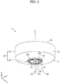
- FIG. 3 is a perspective view of heat sensor 1 when viewed from a direction different from that in FIG. 2 .
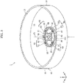
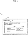
- FIG. 4 is a diagram illustrating a schematic configuration of heat sensor 1. Note that FIG. 3 illustrates a view when cover 18 (see FIG. 8 ) is removed from housing 10.
- heat sensor 1 includes: housing 10 of a cylindrical shape which forms the outline of heat sensor 1; and component mounted substrate 40 which is provided in housing 10.
- component mounted substrate 40 includes: heat detection unit 30 which detects heat of gas; and control unit 50 which determines the presence or absence of fire based on a result obtained at heat detection unit 30.
- Heat detection unit 30 is provided inside of housing 10.
- Heat detection unit 30 has a heat detection element such as a chip thermistor.
- the height of heat detection unit 30 can be made smaller in a case where the heat detection element is a chip thermistor than in a case where the heat detection element is a thermistor provided with a lead wire. Note that the heat detection element is not limited to the chip thermistor.
- the heat detection element is connected to control unit 50 via a wire formed at component mounted substrate 40.
- FIG. 4 illustrates one heat detection unit 30 as one example, but a plurality of heat detection units 30 are actually connected to control unit 50. A configuration of heat detection unit 30 will be described in detail later on.
- Control unit 50 is composed of IC chips such as, for example, a central processing unit (CPU), a random access memory (RAM), and a read only memory (ROM). For example, control unit 50 determines the presence or absence of fire depending on whether or not an average value of voltages outputted from a plurality of heat detection elements is higher than a predefined threshold value. Note that control unit 50 may compare a maximum value or a minimum value of the voltages outputted from the plurality of heat detection elements with the predefined threshold values to determine the presence or absence of fire.
- IC chips such as, for example, a central processing unit (CPU), a random access memory (RAM), and a read only memory (ROM).
- CPU central processing unit
- RAM random access memory
- ROM read only memory
- control unit 50 includes a report circuit (not illustrated) for reporting a result of the determination of the presence or absence of fire.
- the report circuit is connected to, for example, a server serving as an external management device.
- Control unit 50 notifies the server of the presence or absence of fire via the report circuit.
- the report circuit may be connected with, for example, a speaker or a light-emitting diode (LED) for notifying the surroundings that the fire has occurred.
- Heat sensor 1 having the aforementioned configuration is disposed, for example, on the ceiling or a wall of a building such as a factory or a household.
- a description will be provided, referring to, as an example, a case where heat sensor 1 is disposed on the ceiling of the building.
- FIG. 5A is a view illustrating a vertical airflow flowing towards heat sensor 1.
- FIG. 5B is a view illustrating a horizontal airflow flowing towards heat sensor 1.
- FIG. 5A when a heat source is located perpendicularly below heat sensor 1, a vertical airflow generated by the heat source flows towards heat sensor 1.
- FIG. 5B when the heat source is located at a position different from a position located perpendicularly below heat sensor 1, a horizontal airflow flowing along the ceiling flows towards heat sensor 1.
- Heat sensor 1 has a structure thinner than that of a conventional one and also has a structure capable of sensing the heat of gas caused to flow by at least either one of the vertical airflow and the horizontal airflow.
- the structure of heat sensor 1 will be described in detail.
- FIG. 6 is a view illustrating heat sensor 1 with (a) providing an elevation view and (b) providing a bottom view.
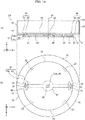
- FIG. 7 is a top view of heat sensor 1.
- FIG. 8 is a partially enlarged sectional view of heat sensor 1 illustrated in (a) of FIG. 6 .
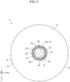
- FIG. 9 is a diagram illustrating a region where heat detection units 30 are arranged in heat sensor 1. Note that FIG. 7 illustrates a case where cover 18 is removed from housing 10. Moreover, FIG. 8 only illustrates a sectional view and does not illustrate a configuration located in a depth direction.
- heat sensor 1 includes housing 10 and component mounted substrate 40.
- FIG. 6 illustrates, by broken lines, the entire shape of component mounted substrate 40 including the outer shape of component mounted substrate 40 viewed through first holes 21 (the same applies to FIG. 9 ).
- Housing 10 has: housing body 15; and projection part 16 which is connected to housing body 15.
- Housing body 15 is of a cylindrical shape having bottom part 11 and side part 12.
- Projection part 16 is of a cylindrical shape and projects outwardly from bottom part 11 of housing body 15.
- the projection dimension of projection part 16 projecting from bottom part 11 is, for example, greater than 0 mm and smaller than 9 mm.
- the diameter of projection part 16 is less than or equal to a half of the diameter of housing body 15.
- housing 10 has opening part 13 which is located oppositely to bottom part 11. Opening part 13 is a portion in contact with the ceiling when heat sensor 1 is installed on the ceiling of the building.
- Housing 10 is formed of, for example, heat-resistant resin.
- Housing 10 has first holes 21 and second holes 22 as inlets and outlets for causing gas flowing from one side to flow out of another side.
- Second holes 22 are connected to first holes 21 via inner path 25, to be described later on.
- first holes 21 and second holes 22 are not provided at center 10a of housing 10 but provided in peripheral region (a region indicated by hatching dots of FIG. 9 ) 10b different from center 10a when heat sensor 1 is viewed form central axis J1 of housing 10.
- the diameter of projection part 16 is less than or equal to a half of the diameter of housing body 15, and thus peripheral region 10b is located more closely to center 10a than the outer periphery.
- first holes 21 and second holes 22 are provided in a region ranging between greater than or equal to 0.2 times and less than or equal to 0.5 times the diameter of the housing body.
- first holes 21 are provided at bottom surface part 16a of projection part 16.
- Each first hole 21 is formed along the outer periphery of bottom surface part 16a and has an arc shape when heat sensor 1 is viewed from center axis J1.
- the shape of first hole 21 is not limited to the arc shape and first hole 21 may have a shape of a polygon, a circle, an oval, or a crescent.
- first holes 21 are arranged in rotational symmetry at equiangular intervals with respect to central axis J1 as a center when heat sensor 1 is viewed from central axis J1.
- first holes 21 may not be arranged at the equiangular intervals with respect to central axis J1 as a center. As illustrated in (a) of FIG. 6 , first holes 21 are provided at bottom surface part 16a with the hole axis of first hole 21 in parallel to central axis J1.
- a plurality of second holes 22 are provided at side surface part 16b of projection part 16.
- Each second hole 22 is provided at side surface part 16b with the hole axis of second hole 22 vertical to central axis J1.
- Each second hole 22 is formed along the outer periphery of side surface part 16b.
- Aplurality of props 23 are provided between second holes 22 adjacent in a circumference direction. The plurality of props 23 connect together housing body 15 and bottom surface part 16a.
- housing 10 has inner path 25 which links together first hole 21 and second hole 22.
- Gas directed to heat sensor 1 by a vertical airflow flows in from first hole 21 and flows out of second hole 22 through inner path 25.
- gas directed to heat sensor 1 by a horizontal airflow flows in from second hole 22 and flows out of first hole 21 via inner path 25.
- the gas directed towards heat sensor 1 by the horizontal airflow flows in from second hole 22 and flows out of another second hole 22 located oppositely to second hole 22 in which the gas has flown.
- Heat detection unit 30 described above is arranged at a position in contact with the gas flowing through inner path 25. Heat detection unit 30 is formed as part of component mounted substrate 40.
- Component mounted substrate 40 is arranged inside of housing 10 and fixed at an inner bottom of bottom part 11 of housing 10 by a fastening member or the like. Component mounted substrate 40 is arranged with the main surface of component mounted substrate 40 orthogonal to central axis J1, that is, along a horizontal direction. Cover 18 is provided inside of housing 10 so as to cover component mounted substrate 40.
- Component mounted substrate 40 includes: substrate body 41, control unit 50 which is mounted on substrate body 41; and a plurality of heat detection elements 32 which are mounted on substrate body 41.
- substrate body 41 has: central part 41c of a plate-like shape; and support units 31 of a bar-like shape extending in all directions from the outer periphery of central part 41c.
- Control unit 50 is mounted at central part 41c of substrate body 41 and each of the plurality of heat detection elements 32 is mounted at an end part of each support unit 31. That is, when heat sensor 1 is viewed from central axis J1, control unit 50 is arranged at the center of housing 10, and heat detection element 32 is arranged more closely to the outer periphery than control unit 50.
- heat detection unit 30 is arranged in correspondence with the position of first hole 21. More specifically, when heat sensor 1 is viewed from central axis J1, heat detection unit 30 is arranged at a position overlapping first hole 21.
- Heat detection unit 30 has: heat detection element 32 and support unit 31 which supports respective heat detection elements 32. Note that support unit 31 is part of substrate body 41. Heat detection element 32 and support unit 31 are arranged inside of housing 10. More specifically, the end part of support unit 31 is arranged so as to make contact with gas passing through inner path 25 (see FIG. 8 ). Consequently, heat detection unit 30 can detect heat of the gas passing through inner path 25.
- peripheral region 10b is located more closely to center 10a than to the outer periphery.
- heat detection unit 30 Since the vertical airflow flows while approaching housing 10 in peripheral region 10b, it is possible to reduce the projection dimension of heat detection unit 30 required for the contact with the vertical airflow. That is, arranging heat detection unit 30 in peripheral region 10b as is the case with the present embodiment makes it is possible to reduce the projection dimension of heat detection unit 30 in a direction of central axis J1, comparted to, for example, a case where heat detection unit 30 is arranged at center 10a of housing 10. Consequently, it is possible to make heat sensor 1 thinner. Moreover, component mounted substrate 40 is arranged with the main surface of component mounted substrate 40 orthogonal to central axis J1, which makes it possible to make heat sensor 1 thinner.
- Heat sensor 1 includes: housing 10 of a cylindrical shape having bottom part 11; and heat detection units 30 which detect heat of gas.
- Housing 10 has first holes 21 and second holes 22 from one side of which gas flows in and from another side of which the gas flows out.
- Heat detection units 30 are arranged in peripheral region 10b different from center 10a of housing 10 when heat sensor 1 is viewed from central axis J1.
- heat detection units 30 in peripheral region 10b makes it possible to reduce the projection dimension of heat detection units 30 in the direction of central axis J1. Consequently, it is possible to make heat sensor 1 thinner.
- each of first holes 21 and second holes 22 is not provided at center 10a of housing 10 but may be provided in peripheral region 10b when heat sensor 1 is viewed from central axis J1.
- structuring heat sensor 1 to have no hole formed at center 10a of housing 10 makes it possible to guide the vertical airflow to peripheral region 10b of housing 10. Consequently, it is possible to reduce the projection dimension of heat detection units 30 in the direction of central axis J1 and make heat sensor 1 thinner.
- housing 10 may have projection part 16 of a cylindrical shape projecting outwardly from bottom part 11, first holes 21 may be provided at bottom surface part 16a of projection part 16, and second holes 22 may be provided at side surface part 16b of projection part 16.
- first holes 21 at bottom surface part 16a and second holes 22 at side surface part 16b makes it possible to provide heat sensor 1 capable of handling both a vertical airflow and a horizontal airflow.
- housing 10 may have inner path 25 which links together first holes 21 and second holes 22, and heat detection units 30 may be arranged at positions in contact with gas flowing through inner path 25.
- heat detection units 30 are arranged in correspondence with first holes 21 when heat sensor 1 is viewed from central axis J1.
- heat detection unit 30 it is possible to detect the heat of the gas flowing in from first hole 21 or the gas flowing out from first hole 21 by use of heat detection unit 30.
- heat detection unit 30 may have heat detection element 32 and support unit 31 which supports heat detection element 32, and heat detection element 32 and support unit 31 may be arranged inside of housing 10.
- heat sensor 1 further includes control unit 50 which determines the presence or absence of fire based on a detection result obtained at heat detection unit 30.
- Control unit 50 may be arranged at the center of housing 10 and heat detection element 32 may be arranged more closely to the outer periphery than control unit 50 when heat sensor 1 is viewed from central axis J1.
- component mounted substrate 40 may be fixed at bottom part 11 of housing 10, component mounted substrate 40 may include: substrate body 41; and control unit 50 and heat detection elements 32 which are mounted on substrate body 41.
- Support unit 31 may be part of substrate body 41.
- Heat sensor 1A according to Variation 1 of the embodiment will be described.
- Variation 1 will be described, referring to an example in which support unit 31 of heat detection unit 30 forming component mounted substrate 40 is formed along the shape of first hole 21.
- FIG. 10 is a top view of heat sensor 1A according to Variation 1. Note that FIG. 10 illustrates a view in a case where cover 18 is removed from housing 10.
- Component mounted substrate 40 is arranged inside of housing 10 and fixed at the inner bottom of bottom part 11 of housing 10 by a fastening member or the like.
- Component mounted substrate 40 includes substrate body 41, control unit 50, and a plurality of heat sensing elements 32.
- Substrate body 41 has: central part 41c; and a pair of support units 31 which are provided on both sides of central part 41c.
- Control unit 50 is mounted on central part 41c of substrate body 41 and the plurality of heat sensing elements 32 are mounted on the end parts of support units 31.
- Heat detection unit 30 is arranged in correspondence with first hole 21 when heat sensor 1A is viewed from central axis J1. More specifically, the end part of support unit 31 has an arc shape and is arranged in correspondence with first hole 21 of the arc shape. Arranging the end part of support unit 31 in correspondence with first hole 21 of heat detection unit 30 of Variation 1 as described above increases a heat receiving area than in the embodiment described above, resulting in a structure such that the heat is easily received from the gas flowing through inner path 25.
- Heat detection unit 30 is arranged in peripheral region 10b different from center 10a of housing 10 when heat sensor 1A is viewed from central axis J1 even in heat sensor 1A of Variation 1. Arranging heat detection unit 30 in peripheral region 10b as described above makes it possible to reduce the projection dimension of heat detection unit 30 in the direction of central axis J1. Consequently, it is possible to make heat sensor 1A thinner.
- Heat sensor 1B according to Variation 2 of the embodiment will be described.
- Variation 2 will be described, referring to an example in which heat detection units 30 are arranged more closely to the outer periphery than the center of housing 10 when heat sensor 1B is viewed from central axis J1.
- FIG. 11 is a view illustrating heat sensor 1B according to Variation 2, with (a) providing an elevation view and (b) providing a bottom view.
- FIG. 12 is a view illustrating a region where heat detection units 30 are arranged in heat sensor 1B according to Variation 2.
- heat sensor 1B includes housing 10 and component mounted substrate 40.
- FIG. 11 illustrates, by broken lines, the entire outer shape of component mounted substrate 40 including the outer shape of component mounted substrate 40 viewed through first holes 21 (the same applies to FIG. 12 ).
- Housing 10 has: housing body 15; and projection part 16 which is connected to housing body 15.
- Housing body 15 is of a cylindrical shape having bottom part 11 and side part 12.
- Projection part 16 is of a cylindrical shape projecting outwardly from bottom part 11 of housing body 15.
- the diameter of projection part 16 in the present variation is greater than 0.5 times and smaller than one times the diameter of housing body 15.
- first holes 21 and second holes 22 are not provided at center 10a of housing 10 but provided in peripheral region (a region indicated by a hatching dot of FIG. 12 ) 10b different from center 10a when heat sensor 1B is viewed from central axis J1.
- the diameter of projection part 16 is 0.5 times greater than the diameter of housing body 15, and thus peripheral region 10b is located more closely to the outer periphery than to center 10a.
- first holes 21 and second holes 22 are provided in a region ranging between greater than 0.5 times and less than one times the diameter of housing body 15.
- heat detection units 30 are arranged in peripheral region 10b different from center 10a of housing 10 when heat sensor 1B is viewed from central axis J1. Note that peripheral region 10b of the present variation is located more closely to the outer periphery than to center 10a.
- peripheral region 10b is located more closely to the outer periphery than to the center of housing 10 when heat sensor 1B is viewed from central axis J1.
- heat sensor 1C according to Variation 3 of the embodiment will be described. Variation 3 will be described, referring to an example in which heat sensor 1C has two heat detection units 30 and two first holes 21.
- FIG. 13 is a view illustrating heat sensor 1C according to Variation 3 with (a) providing an elevation view and (b) providing a bottom view. Moreover, FIG. 13 illustrates, by broken lines, the entire outer shape of component mounted substrate 40 including the outer shape of component mounted substrate 40 viewed through first hole 21 (the same applies to FIGS. 14 to 17 and FIG. 19 ).
- housing 10 of heat sensor 1C has: housing body 15; and projection part 16 which is connected to housing body 15.
- Housing 10 has first holes 21 and second holes 22.
- Second holes 22 are connected to first holes 21 via an inner path of housing 10.
- each of first holes 21 and second holes 22 is not provided at center 10a of housing 10 but provided in peripheral region 10b (see FIG. 12 ) different from center 10a when heat sensor 1C is viewed from central axis J1 of housing 10.
- first holes 21 are provided at bottom surface part 16a of projection part 16.
- Each first hole 21 is formed near the outer periphery of bottom surface part 16a and has an arc shape when heat sensor 1C is viewed from central axis J1.
- the shape of first hole 21 is not limited to the arc shape and may be a shape other than the arc shape.
- the shape of first hole 21 may be, for example, a polygon such as a rectangle, a circle, an oval, a crescent, or a shape obtained by combining together the aforementioned shapes.
- first holes 21 are arranged in rotational symmetry at intervals of 180 degrees with respect to central axis J1 as a center when heat sensor 1C is viewed from central axis J1. Note that first holes 21 may not be arranged at the aforementioned angular intervals or may not be arranged in rotational symmetry with respect to central axis J1 as a center.
- Heat detection units 30 are arranged at positions in contact with the gas flowing through inner path 25. Heat detection units 30 are arranged in correspondence with the positions of first holes 21 when heat sensor 1C is viewed from central axis J1. More specifically, heat detection units 30 are arranged at positions overlapping first holes 21 when heat sensor 1C is viewed from central axis J1.
- FIG. 14 is a diagram illustrating heat sensor 1D according to Variation 4 with (a) providing an elevation view and (b) providing a bottom view.
- housing 10 of heat sensor 1D has: housing body 15; and projection part 16 which is connected to housing body 15.
- Housing 10 has first holes 21 and second holes 22. Second holes 22 are connected to first hole 21 via an inner path of housing 10.
- each of first holes 21 and second holes 22 is not provided at center 10a of housing 10 but provided in peripheral region 10b (see FIG. 12 ) different from center 10a when heat sensor 1D is viewed from central axis J1 of housing 10.
- first holes 21 are provided at bottom surface part 16a of projection part 16.
- Each first hole 21 is formed near the outer periphery of bottom surface part 16a and has an oval shape when heat sensor 1D is viewed from central axis J1.
- the shape of first hole 21 is not limited to the oval shape and may be a shape other than the oval shape.
- the shape of first hole 21 may be, for example, a polygon such as a rectangle, a circle, a crescent, or a shape obtained by combining together the aforementioned shapes.
- first holes 21 are arranged in rotational symmetry at intervals of 180 degrees with respect to central axis J1 as a center when heat sensor 1D is viewed from central axis J1. Note that each first hole 21 may not be arranged at the aforementioned angular intervals and may not be arranged in rotational symmetry with respect to central axis J1 as a center.
- Heat detection units 30 are arranged at positions in contact with the gas flowing through inner path 25. Heat detection units 30 are arranged in correspondence with the positions of first holes 21 when heat sensor 1D is viewed from central axis J1. More specifically, heat detection units 30 are arranged at positions overlapping first holes 21 when heat sensor 1D is viewed from central axis J1.
- heat sensor 1E according to Variation 5 of the embodiment will be described. Variation 5 will be described, referring to an example in which heat sensor 1E has three heat detection units 30 and three first holes 21.
- FIG. 15 is a bottom view illustrating heat sensor 1E according to Variation 5.
- Housing 10 of heat sensor 1E has: housing body 15; and projection part 16 which is connected to housing body 15.
- Housing 10 has first holes 21 and second holes 22.
- Second holes 22 are connected to first holes 21 via an inner path of housing 10.
- first holes 21 and second holes 22 is not provided at center 10a of housing 10 but provided in peripheral region 10b (see FIG. 12 ) different from center 10a when heat sensor 1E is viewed from central axis J1.
- first holes 21 are provided at bottom surface part 16a of projection part 16.
- Each first hole 21 is formed near the outer periphery of bottom surface part 16a and has an arc shape when heat sensor 1E is viewed from central axis J1.
- the shape of first hole 21 is not limited to the arc shape and may be a shape other than the arc shape.
- the shape of first hole 21 may be, for example, a polygon such as a rectangle, a circle, an oval, a crescent, or a shape obtained by combining together the aforementioned shapes.
- first holes 21 are arranged in rotational symmetry at intervals of 120 degrees with respect to central axis J1 as a center when heat sensor 1E is viewed from central axis J1.
- first holes 21 may not be arranged at the aforementioned angular intervals and may not be arranged in rotational symmetry with respect to central axis J1 as a center.
- Heat detection units 30 are arranged at positions in contact with the gas flowing through inner path 25. Heat detection units 30 are arranged in correspondence with the positions of first holes 21 when heat sensor 1E is viewed from central axis J1. More specifically, heat detection units 30 are arranged at positions overlapping first holes 21 when heat sensor 1E is viewed from central axis J1.
- FIG. 16 is a bottom view illustrating heat sensor 1F according to Variation 6 with (a) providing an elevation view and (b) providing a bottom view.
- Housing 10 of heat sensor 1F has: housing body 15; and projection part 16 which is connected to housing body 15.
- Housing 10 has first holes 21 and second holes 22. Second holes 22 are connected to first holes 21 via an inner path of housing 10.
- first holes 21 and second holes 22 is not provided at center 10a of housing 10 but provided in peripheral region 10b (see FIG. 12 ) different from center 10a when heat sensor 1F is viewed from central axis J1.
- first holes 21 are provided at bottom surface part 16a of projection part 16.
- Each first hole 21 is formed near the outer periphery of bottom surface part 16a and has an arc shape when heat sensor 1F is viewed from central axis J1.
- the shape of first hole 21 is not limited to the arc shape and may be a shape other than the arc shape.
- the shape of first hole 21 may be, for example, a polygon such as a rectangle, a circle, an oval, or a crescent.
- three first holes 21 are arranged at different angular intervals of 90 degrees and 180 degrees with respect to central axis J1 as a center when heat sensor 1F is viewed from central axis J1.
- first holes 21 may not be arranged at the aforementioned angular intervals with respect to central axis J1 as a center.
- Heat detection units 30 are arranged at positions in contact with the gas flowing through inner path 25. Heat detection units 30 are arranged in correspondence with the positions of first holes 21 when heat sensor 1F is viewed from central axis J1. That is, three heat detection units 30 are also arranged at different angular intervals of 90 degrees and 180 degrees with respect to central axis J1 as a center. Note that heat detection units 30 may not be arranged at the aforementioned angular intervals with respect to central axis J1 as a center.
- Variation 7 will be described, referring to an example in which the positions of a plurality of heat detection units 30 and the positions of a plurality of first holes 21 partially agree with each other but do not partially agree with each other in other parts when heat sensor 1G is viewed from central axis J1.
- FIG. 17 is a diagram illustrating heat sensor 1G according to Variation 7 with (a) providing an elevation view and (b) providing a bottom view.
- housing 10 of heat sensor 1G has: housing body 15; and projection part 16 which is connected to housing body 15.
- Housing 10 has first holes 21 and second holes 22.
- Second holes 22 are connected to first holes 21 via an inner path of housing 10.
- each of first holes 21 and second holes 22 is not provided in center 10a of housing 10 but provided in peripheral region 10b (see FIG. 12 ) different from center 10a when heat sensor 1G is viewed from central axis J1.
- first holes 21 are provided at bottom surface part 16a of projection part 16.
- Each first hole 21 is formed near the outer periphery of bottom surface part 16a and has an arc shape when heat sensor 1G is viewed from central axis J1.
- the shape of first hole 21 is not limited to the arc shape and may be a shape other than the arc shape.
- the shape of first hole 21 may be, for example, a polygon such as a rectangle, a circle, an oval, a crescent, or a shape obtained by combining together the aforementioned shapes.
- first holes 21 are arranged in rotational symmetry at intervals of 180 degrees with respect to central axis J1 as a center when heat sensor 1G is viewed from central axis J1. Note that first holes 21 may not be arranged at the aforementioned angular intervals or may not be arranged in rotational symmetry with respect to central axis J1 as a center.
- Four heat detection units 30 are provided in housing 10. Two heat detection units 30 of four heat detection units 30 are provided at positions in correspondence with first holes 21 and other two heat detection units 30 are provided at positions not in correspondence with first holes 21 when heat sensor 1G is viewed from central axis J1. More specifically, two heat detection units 30 are arranged at the positions overlapping first holes 21 and other two heat detection units 30 are arranged at the positions not overlapping first holes 21. Other two heat detection units 30 are covered with bottom surface part 16a when viewed from central axis J1. As is the case with heat sensor 1G of Variation 7, first holes 21 and heat detection units 30 do not necessarily have to be provided at positions in agreement with each other and may be provided at positions not in agreement with each other when viewed from central axis J1.
- FIG. 18 is a bottom view illustrating heat sensor 1H according to Variation 8.
- Housing 10 of heat sensor 1H has: housing body 15; and projection part 16 which is connected to housing body 15.
- Housing 10 has first holes 21 and second holes 22.
- Second holes 22 are connected to first holes 21 via an inner path of housing 10.
- first holes 21 and second holes 22 is not provided at center 10a of housing 10 but provided in peripheral region 10b (see FIG. 12 ) different from center 10a when heat sensor 1H is viewed from central axis J1.
- first holes 21 are provided at bottom surface part 16a of projection part 16.
- Each first hole 21 is formed along the outer periphery of bottom surface part 16a and has an arc shape when heat sensor 1H is viewed from central axis J1.
- the shape of first hole 21 is not limited to the arc shape and may be a shape other than the arc shape.
- the shape of first hole 21 may be, for example, a polygon, a triangle, an oval, a crescent, or a shape obtained by combining together the aforementioned shapes.
- first holes 21 are arranged in rotational symmetry at intervals of 90 degrees with respect to central axis J1 as a center when heat sensor 1H is viewed from central axis J1.
- first holes 21 may not be arranged at the aforementioned angular intervals and may not be arranged in rotational symmetry with respect to central axis J1 as a center.
- Four heat detection units 30 are provided in housing 10. All of four heat detection units 30 are provided at positions not in correspondence with first holes 21 when heat sensor 1H is viewed from central axis J1. More specifically, four heat detection units 30 are arranged at the positions not overlapping first holes 21. Four heat detection units 30 are covered by bottom surface part 16a when viewed from central axis J1.
- Variation 9 will be described, referring to an example in which the positions of a plurality of heat detection units 30 and the positions of a plurality of first holes 21 partially agree with each other and do not partially agree with each other in other parts when heat sensor 1i is viewed from central axis J1.
- FIG. 19 is a view illustrating heat sensor 1i according to Variation 9 with (a) providing an elevation view and (b) providing a bottom view.
- housing 10 of heat sensor 1i has: housing body 15; and projection part 16 which is connected to housing body 15.
- Housing 10 has first holes 21 and second holes 22.
- Second holes 22 are connected to first holes 21 via an inner path of housing 10.
- each of first holes 21 and second hole 22 is not provided at center 10a of housing 10 but provided in peripheral region 10b (see FIG. 12 ) different from center 10a when heat sensor 1i is viewed from central axis J1.
- first holes 21 are provided at bottom surface part 16a of projection part 16.
- Each of first holes 21 is formed along the outer periphery of bottom surface part 16a and has an arc shape when heat sensor 1i is viewed from central axis J1.
- the shape of first hole 21 is not limited to the arc shape and may have a shape other than the arc shape.
- the shape of first hole 21 may be of a shape, for example, a polygon, an oval, a crescent, or a shape obtained by combining together the aforementioned shapes.
- first holes 21 are arranged in rotational symmetry with respect to central axis J1 as a center when heat sensor 1i is viewed from central axis J1. Note that first holes 21 may not be arranged in rotational symmetry with respect to central axis J1 as a center.
- first holes 21 and heat detection units 30 are arranged in housing 10. Two of four heat detection units 30 are provided at positions in correspondence with first holes 21 and other two heat detection units 30 are provided at positions not in correspondence with first holes 21 when heat sensor 1i is viewed from central axis J1. More specifically, two heat detection units 30 are arranged at the positions overlapping first holes 21 and other two heat detection units 30 are arranged at the positions not overlapping first holes 21. Other two heat detection units 30 are covered by bottom surface part 16a when viewed from central axis J1. As is the case with heat sensor 1i of Variation 9, first holes 21 and heat detection units 30 do not necessarily have to be provided at the overlapping positions and may be provided at non-overlapping positions when viewed from central axis J1.
- heat detection units 30 are arranged in peripheral region 10b different from center 10a of housing 10 when heat sensors 1C to 1i are viewed from central axis J1. Note that peripheral region 10b of Variations 3 to 9 is located more closely to the outer periphery than to center 10a.
- Heat sensors 1 to 1i of the present disclosure have been described above based on the aforementioned embodiments, but the present disclosure is not limited to the embodiment described above.
- heat sensors 1 to 1i may also function as a smoke detection unit which detects smoke.
- heat sensors 1 to 1i may be disposed not only on the ceiling but also on a wall. Heat sensors 1 to 1i may be supplied with a power by a commercial power source or may be supplied with a power by a battery provided inside of housing 10.
- housing 10 of heat sensors 1 to 1i are not limited to a cylindrical shape and may be a square tubular shape.
- the number of heat detection units 30 provided in housing 10 is not limited to a plural number and may also be one.
- the present disclosure also include: a mode obtained by making various modifications conceivable by those skilled in the art to the embodiment; and a mode realized by combining together the components and the functions in the embodiment in a desired manner within a range not departing from the spirits of the present disclosure.
Landscapes
- Physics & Mathematics (AREA)
- General Physics & Mathematics (AREA)
- Business, Economics & Management (AREA)
- Emergency Management (AREA)
- Fire-Detection Mechanisms (AREA)
Abstract
Description
- The present disclosure relates to a heat sensor which senses heat generated by fire or the like.
- Heat sensors which sense heat generated by fire or the like have been conventionally known. Patent Literature 1 (PTL1) discloses, as one example of a heat sensor of this type, a heat sensor which includes: a housing body; a thermistor which is arranged outside of the housing body; and a protection frame which is provided so as to cover the outside of the thermistor. In the aforementioned heat sensor, heat of gas flowing towards the heat sensor upon the fire is detected by the use of the thermistor arranged outside of the housing body.
- PTL 1: Japanese Unexamined Patent Application Publication No.
H10-334360 - There have been demands in recent years for making a heat sensor thinner for the purpose of improving the appearance of the inside of a building where the heat sensor is installed. However, the heat sensor disclosed in
PTL 1 faces a problem that the thickness of the heat sensor becomes large. - Thus, it is an object of the present disclosure to make a heat sensor thinner.
- To address the object described above, a heat sensor according to one aspect of the present disclosure includes: a housing of a cylindrical shape having a bottom part; and a heat detection unit configured to detect heat of gas, wherein the housing has a first hole and a second hole from one side of which gas flows in and from another side of which the gas flows out, and the heat detection unit is arranged in a peripheral region different from a center of the housing when the heat sensor is viewed from a central axis of the housing.
- The present disclosure makes it possible to make a heat sensor thinner.
-
-
FIG. 1 is a view illustrating a heat sensor of a comparative example. -
FIG. 2 is a perspective view of a heat sensor according to an embodiment. -
FIG. 3 is a perspective view of the heat sensor according to the embodiment when viewed from a direction different from that inFIG. 2 . -
FIG. 4 is a diagram illustrating a schematic configuration of the heat sensor according to the embodiment. -
FIG. 5A is a view illustrating a vertical airflow flowing towards the heat sensor according to the embodiment. -
FIG. 5B is a view illustrating a horizontal airflow flowing towards the heat sensor of the embodiment. -
FIG. 6 is a view illustrating the heat sensor according to the embodiment with (a) providing an elevation view and (b) providing a bottom view. -
FIG. 7 is a top view of the heat sensor according to the embodiment. -
FIG. 8 is a partially enlarged sectional view of the heat sensor illustrated in (a) ofFIG. 6 . -
FIG. 9 is a view illustrating a region where a heat detection unit is arranged in the heat sensor according to the embodiment. -
FIG. 10 is a top view of a heat sensor according toVariation 1 of the embodiment. -
FIG. 11 is a view illustrating a heat sensor according toVariation 2 of the embodiment with (a) providing an elevation view and (b) providing a bottom view. -
FIG. 12 is a view illustrating a region where a heat detection unit is arranged in the heat sensor according toVariation 2 of the embodiment. -
FIG. 13 is a view illustrating a heat sensor according to Variation 3 of the embodiment with (a) providing an elevation view and (b) providing a bottom view. -
FIG. 14 is a view illustrating a heat sensor according to Variation 4 of the embodiment with (a) providing an elevation view and (b) providing a bottom view. -
FIG. 15 is a bottom view illustrating a heat sensor according to Variation 5 of the embodiment. -
FIG. 16 is a bottom view illustrating a heat sensor according to Variation 6 of the embodiment with (a) providing an elevation view and (b) providing a bottom view. -
FIG. 17 is a view illustrating a heat sensor according to Variation 7 of the embodiment with (a) providing an elevation view and (b) providing a bottom view. -
FIG. 18 is a bottom view illustrating a heat sensor according to Variation 8 of the embodiment. -
FIG. 19 is a view illustrating a heat sensor according to Variation 9 of the embodiment with (a) providing an elevation view and (b) providing a bottom view. - First, background reaching the present disclosure will be described with reference to a comparative example of
FIG. 1. FIG. 1 is a view illustratingheat sensor 101 of the comparative example. -
Heat sensor 101 of the comparative example includes:housing 110 of a cylindrical shape havingbottom part 111; andheat detection unit 130 which detects heat of gas.Heat detection unit 130 is, for example, a thermistor provided with a lead wire, which is arranged perpendicularly belowbottom part 111 and arranged at the center ofhousing 110 when viewed vertically from the bottom. Moreover,housing 110 is provided withprotection frame 116 which coversheat detection unit 130. - As illustrated in
FIG. 1 , when there is a heat source such as frame perpendicularly belowheat sensor 101, a vertical airflow (updraft) flowing towardsheat sensor 101 is generated. The vertical airflow changes a flow direction nearheat sensor 101 under the influence of the outer shape ofheat sensor 101, resulting in a change to a flow in a diagonal direction including a flow component directed from the center towards the outer periphery ofhousing 110. Thus,heat detection unit 130 needs to be arranged inheat sensor 101 of the comparative example in a manner remarkably projecting perpendicularly downward to make contact with the vertical airflow. Consequently, there arises a problem that the projection dimension ofprotection frame 116 coveringheat detection unit 130 increases, resulting in an increase in the thickness ofheat sensor 101. - On the contrary, a heat detection unit is arranged in a peripheral region different from the center of a housing in a heat sensor of the present disclosure when the heat sensor is viewed perpendicularly from a bottom. The vertical airflow flows while approaching the housing in the peripheral region, and thus it is possible to reduce the projection dimension of the heat sensor required for the contact with the vertical airflow. Consequently, it is possible to make the heat sensor thinner.
- Hereinafter, the heat sensor according to the embodiment of the present disclosure will be described in detail with reference to the drawings. Note that each embodiment described below illustrates one detailed example of the present disclosure. Therefore, numerical values, shapes, materials, components, arrangement, and connection modes of the components, etc., each form one example and are not intended to limit the present disclosure. Therefore, of the components in the embodiment described below, those not disclosed in any independent claim indicating the highest concept of the present disclosure will be described as optional components.
- Moreover, each drawing is a schematic diagram and does not necessarily provide a precise illustration. Therefore, for example, scaling do not necessarily agree with each other in the different drawings. Moreover, substantially same configurations are practically provided with same signs in the drawings and overlapping explanation will be omitted or simplified.
- Moreover, an x-axis, a y-axis, and a z-axis illustrate three axes of a three-dimensional orthogonal coordinate system in the present description and drawings. In the present embodiment, a z-axis direction is a vertical direction and a direction vertical to the z-axis (a direction parallel to a plane xy) is a horizontal direction. Note that a negative direction of the z-axis is directed vertically downward.
- The configuration of the heat sensor according to the embodiment will be described with reference to
FIGS. 2 to 9 . The heat sensor according to the present embodiment is a fire report device which detects, for example, fire in a building and reports, to an outside, that the fire has occurred. -
FIG. 2 is a perspective view ofheat sensor 1 according to the embodiment.FIG. 3 is a perspective view ofheat sensor 1 when viewed from a direction different from that inFIG. 2 .FIG. 4 is a diagram illustrating a schematic configuration ofheat sensor 1. Note thatFIG. 3 illustrates a view when cover 18 (seeFIG. 8 ) is removed fromhousing 10. - As illustrated in
FIGS. 2 and3 ,heat sensor 1 includes:housing 10 of a cylindrical shape which forms the outline ofheat sensor 1; and component mountedsubstrate 40 which is provided inhousing 10. As illustrated inFIG. 4 , component mountedsubstrate 40 includes:heat detection unit 30 which detects heat of gas; andcontrol unit 50 which determines the presence or absence of fire based on a result obtained atheat detection unit 30. -
Heat detection unit 30 is provided inside ofhousing 10.Heat detection unit 30 has a heat detection element such as a chip thermistor. For example, the height ofheat detection unit 30 can be made smaller in a case where the heat detection element is a chip thermistor than in a case where the heat detection element is a thermistor provided with a lead wire. Note that the heat detection element is not limited to the chip thermistor. - The heat detection element is connected to control
unit 50 via a wire formed at component mountedsubstrate 40. Note thatFIG. 4 illustrates oneheat detection unit 30 as one example, but a plurality ofheat detection units 30 are actually connected to controlunit 50. A configuration ofheat detection unit 30 will be described in detail later on. -
Control unit 50 is composed of IC chips such as, for example, a central processing unit (CPU), a random access memory (RAM), and a read only memory (ROM). For example,control unit 50 determines the presence or absence of fire depending on whether or not an average value of voltages outputted from a plurality of heat detection elements is higher than a predefined threshold value. Note thatcontrol unit 50 may compare a maximum value or a minimum value of the voltages outputted from the plurality of heat detection elements with the predefined threshold values to determine the presence or absence of fire. - Moreover,
control unit 50 includes a report circuit (not illustrated) for reporting a result of the determination of the presence or absence of fire. The report circuit is connected to, for example, a server serving as an external management device.Control unit 50 notifies the server of the presence or absence of fire via the report circuit. The report circuit may be connected with, for example, a speaker or a light-emitting diode (LED) for notifying the surroundings that the fire has occurred. -
Heat sensor 1 having the aforementioned configuration is disposed, for example, on the ceiling or a wall of a building such as a factory or a household. Hereinafter, a description will be provided, referring to, as an example, a case whereheat sensor 1 is disposed on the ceiling of the building. -
FIG. 5A is a view illustrating a vertical airflow flowing towardsheat sensor 1.FIG. 5B is a view illustrating a horizontal airflow flowing towardsheat sensor 1. - As illustrated in
FIG. 5A , when a heat source is located perpendicularly belowheat sensor 1, a vertical airflow generated by the heat source flows towardsheat sensor 1. As illustrated inFIG. 5B , when the heat source is located at a position different from a position located perpendicularly belowheat sensor 1, a horizontal airflow flowing along the ceiling flows towardsheat sensor 1. -
Heat sensor 1 according to the present embodiment has a structure thinner than that of a conventional one and also has a structure capable of sensing the heat of gas caused to flow by at least either one of the vertical airflow and the horizontal airflow. Hereinafter, the structure ofheat sensor 1 will be described in detail. -
FIG. 6 is a view illustratingheat sensor 1 with (a) providing an elevation view and (b) providing a bottom view.FIG. 7 is a top view ofheat sensor 1.FIG. 8 is a partially enlarged sectional view ofheat sensor 1 illustrated in (a) ofFIG. 6 .FIG. 9 is a diagram illustrating a region whereheat detection units 30 are arranged inheat sensor 1. Note thatFIG. 7 illustrates a case wherecover 18 is removed fromhousing 10. Moreover,FIG. 8 only illustrates a sectional view and does not illustrate a configuration located in a depth direction. - As illustrated in
FIGS. 6 to 8 ,heat sensor 1 includeshousing 10 and component mountedsubstrate 40. Note that (b) ofFIG. 6 illustrates, by broken lines, the entire shape of component mountedsubstrate 40 including the outer shape of component mountedsubstrate 40 viewed through first holes 21 (the same applies toFIG. 9 ). -
Housing 10 has:housing body 15; andprojection part 16 which is connected tohousing body 15.Housing body 15 is of a cylindrical shape havingbottom part 11 andside part 12.Projection part 16 is of a cylindrical shape and projects outwardly frombottom part 11 ofhousing body 15. The projection dimension ofprojection part 16 projecting frombottom part 11 is, for example, greater than 0 mm and smaller than 9 mm. The diameter ofprojection part 16 is less than or equal to a half of the diameter ofhousing body 15. - Moreover,
housing 10 has openingpart 13 which is located oppositely tobottom part 11. Openingpart 13 is a portion in contact with the ceiling whenheat sensor 1 is installed on the ceiling of the building.Housing 10 is formed of, for example, heat-resistant resin. -
Housing 10 has first holes 21 andsecond holes 22 as inlets and outlets for causing gas flowing from one side to flow out of another side.Second holes 22 are connected tofirst holes 21 viainner path 25, to be described later on. - Each of
first holes 21 andsecond holes 22 is not provided atcenter 10a ofhousing 10 but provided in peripheral region (a region indicated by hatching dots ofFIG. 9 ) 10b different fromcenter 10a whenheat sensor 1 is viewed form central axis J1 ofhousing 10. In the present embodiment, the diameter ofprojection part 16 is less than or equal to a half of the diameter ofhousing body 15, and thusperipheral region 10b is located more closely tocenter 10a than the outer periphery. More specifically,first holes 21 andsecond holes 22 are provided in a region ranging between greater than or equal to 0.2 times and less than or equal to 0.5 times the diameter of the housing body. - As illustrated in (b) of
FIG. 6 , a plurality offirst holes 21 are provided atbottom surface part 16a ofprojection part 16. Eachfirst hole 21 is formed along the outer periphery ofbottom surface part 16a and has an arc shape whenheat sensor 1 is viewed from center axis J1. Note that the shape offirst hole 21 is not limited to the arc shape andfirst hole 21 may have a shape of a polygon, a circle, an oval, or a crescent. Moreover,first holes 21 are arranged in rotational symmetry at equiangular intervals with respect to central axis J1 as a center whenheat sensor 1 is viewed from central axis J1. Note thatfirst holes 21 may not be arranged at the equiangular intervals with respect to central axis J1 as a center. As illustrated in (a) ofFIG. 6 ,first holes 21 are provided atbottom surface part 16a with the hole axis offirst hole 21 in parallel to central axis J1. - As illustrated in
FIG. 3 and (a) ofFIG. 6 , a plurality ofsecond holes 22 are provided atside surface part 16b ofprojection part 16. Eachsecond hole 22 is provided atside surface part 16b with the hole axis ofsecond hole 22 vertical to central axis J1. Eachsecond hole 22 is formed along the outer periphery ofside surface part 16b. Aplurality ofprops 23 are provided betweensecond holes 22 adjacent in a circumference direction. The plurality ofprops 23 connect togetherhousing body 15 andbottom surface part 16a. - As illustrated in
FIG. 8 ,housing 10 hasinner path 25 which links togetherfirst hole 21 andsecond hole 22. Gas directed toheat sensor 1 by a vertical airflow flows in fromfirst hole 21 and flows out ofsecond hole 22 throughinner path 25. On the other hand, gas directed toheat sensor 1 by a horizontal airflow flows in fromsecond hole 22 and flows out offirst hole 21 viainner path 25. Alternatively, the gas directed towardsheat sensor 1 by the horizontal airflow flows in fromsecond hole 22 and flows out of anothersecond hole 22 located oppositely tosecond hole 22 in which the gas has flown.Heat detection unit 30 described above is arranged at a position in contact with the gas flowing throughinner path 25.Heat detection unit 30 is formed as part of component mountedsubstrate 40. - Component mounted
substrate 40 is arranged inside ofhousing 10 and fixed at an inner bottom ofbottom part 11 ofhousing 10 by a fastening member or the like. Component mountedsubstrate 40 is arranged with the main surface of component mountedsubstrate 40 orthogonal to central axis J1, that is, along a horizontal direction.Cover 18 is provided inside ofhousing 10 so as to cover component mountedsubstrate 40. - Component mounted
substrate 40 includes:substrate body 41,control unit 50 which is mounted onsubstrate body 41; and a plurality ofheat detection elements 32 which are mounted onsubstrate body 41. - As illustrated in
FIG. 7 ,substrate body 41 has:central part 41c of a plate-like shape; andsupport units 31 of a bar-like shape extending in all directions from the outer periphery ofcentral part 41c.Control unit 50 is mounted atcentral part 41c ofsubstrate body 41 and each of the plurality ofheat detection elements 32 is mounted at an end part of eachsupport unit 31. That is, whenheat sensor 1 is viewed from central axis J1,control unit 50 is arranged at the center ofhousing 10, andheat detection element 32 is arranged more closely to the outer periphery thancontrol unit 50. Moreover, whenheat sensor 1 is viewed from central axis J1,heat detection unit 30 is arranged in correspondence with the position offirst hole 21. More specifically, whenheat sensor 1 is viewed from central axis J1,heat detection unit 30 is arranged at a position overlappingfirst hole 21. -
Heat detection unit 30 has:heat detection element 32 andsupport unit 31 which supports respectiveheat detection elements 32. Note thatsupport unit 31 is part ofsubstrate body 41.Heat detection element 32 andsupport unit 31 are arranged inside ofhousing 10. More specifically, the end part ofsupport unit 31 is arranged so as to make contact with gas passing through inner path 25 (seeFIG. 8 ). Consequently,heat detection unit 30 can detect heat of the gas passing throughinner path 25. - Moreover, as illustrated in
FIG. 9 , whenheat sensor 1 is viewed from central axis J1,heat detection units 30 are arranged inperipheral region 10b different fromcenter 10a ofhousing 10. In the present embodiment,peripheral region 10b is located more closely tocenter 10a than to the outer periphery. - Since the vertical airflow flows while approaching
housing 10 inperipheral region 10b, it is possible to reduce the projection dimension ofheat detection unit 30 required for the contact with the vertical airflow. That is, arrangingheat detection unit 30 inperipheral region 10b as is the case with the present embodiment makes it is possible to reduce the projection dimension ofheat detection unit 30 in a direction of central axis J1, comparted to, for example, a case whereheat detection unit 30 is arranged atcenter 10a ofhousing 10. Consequently, it is possible to makeheat sensor 1 thinner. Moreover, component mountedsubstrate 40 is arranged with the main surface of component mountedsubstrate 40 orthogonal to central axis J1, which makes it possible to makeheat sensor 1 thinner. -
Heat sensor 1 according to the present embodiment includes:housing 10 of a cylindrical shape havingbottom part 11; andheat detection units 30 which detect heat of gas.Housing 10 has first holes 21 andsecond holes 22 from one side of which gas flows in and from another side of which the gas flows out.Heat detection units 30 are arranged inperipheral region 10b different fromcenter 10a ofhousing 10 whenheat sensor 1 is viewed from central axis J1. - As described above, arranging
heat detection units 30 inperipheral region 10b makes it possible to reduce the projection dimension ofheat detection units 30 in the direction of central axis J1. Consequently, it is possible to makeheat sensor 1 thinner. - Moreover, each of
first holes 21 andsecond holes 22 is not provided atcenter 10a ofhousing 10 but may be provided inperipheral region 10b whenheat sensor 1 is viewed from central axis J1. - As described above, structuring
heat sensor 1 to have no hole formed atcenter 10a ofhousing 10 makes it possible to guide the vertical airflow toperipheral region 10b ofhousing 10. Consequently, it is possible to reduce the projection dimension ofheat detection units 30 in the direction of central axis J1 and makeheat sensor 1 thinner. - Moreover,
housing 10 may haveprojection part 16 of a cylindrical shape projecting outwardly frombottom part 11,first holes 21 may be provided atbottom surface part 16a ofprojection part 16, andsecond holes 22 may be provided atside surface part 16b ofprojection part 16. - As described above, providing
first holes 21 atbottom surface part 16a andsecond holes 22 atside surface part 16b makes it possible to provideheat sensor 1 capable of handling both a vertical airflow and a horizontal airflow. - Moreover,
housing 10 may haveinner path 25 which links together first holes 21 andsecond holes 22, andheat detection units 30 may be arranged at positions in contact with gas flowing throughinner path 25. - Consequently, it is possible to detect the heat of the gas flowing through
inner path 25 by use ofheat detection units 30. - Moreover,
heat detection units 30 are arranged in correspondence withfirst holes 21 whenheat sensor 1 is viewed from central axis J1. - Consequently, it is possible to detect the heat of the gas flowing in from
first hole 21 or the gas flowing out fromfirst hole 21 by use ofheat detection unit 30. - Moreover,
heat detection unit 30 may haveheat detection element 32 andsupport unit 31 which supportsheat detection element 32, andheat detection element 32 andsupport unit 31 may be arranged inside ofhousing 10. - Consequently, it is possible to detect the heat inside of
housing 10 by use ofheat detection unit 30. - Moreover,
heat sensor 1 further includescontrol unit 50 which determines the presence or absence of fire based on a detection result obtained atheat detection unit 30.Control unit 50 may be arranged at the center ofhousing 10 andheat detection element 32 may be arranged more closely to the outer periphery thancontrol unit 50 whenheat sensor 1 is viewed from central axis J1. - Consequently, it is possible to detect heat in a region near the outer periphery of
housing 10 by use ofheat detection element 32. - Moreover, component mounted
substrate 40 may be fixed atbottom part 11 ofhousing 10, component mountedsubstrate 40 may include:substrate body 41; andcontrol unit 50 andheat detection elements 32 which are mounted onsubstrate body 41.Support unit 31 may be part ofsubstrate body 41. - As described above, mounting
heat detection elements 32 onsubstrate body 41 makes it possible to reduce the height ofheat detection unit 30. Consequently, it is possible to makeheat sensor 1 thinner. - Next,
heat sensor 1A according toVariation 1 of the embodiment will be described.Variation 1 will be described, referring to an example in which supportunit 31 ofheat detection unit 30 forming component mountedsubstrate 40 is formed along the shape offirst hole 21. -
FIG. 10 is a top view ofheat sensor 1A according toVariation 1. Note thatFIG. 10 illustrates a view in a case wherecover 18 is removed fromhousing 10. - Component mounted
substrate 40 is arranged inside ofhousing 10 and fixed at the inner bottom ofbottom part 11 ofhousing 10 by a fastening member or the like. Component mountedsubstrate 40 includessubstrate body 41,control unit 50, and a plurality ofheat sensing elements 32. -
Substrate body 41 has:central part 41c; and a pair ofsupport units 31 which are provided on both sides ofcentral part 41c.Control unit 50 is mounted oncentral part 41c ofsubstrate body 41 and the plurality ofheat sensing elements 32 are mounted on the end parts ofsupport units 31. -
Heat detection unit 30 is arranged in correspondence withfirst hole 21 whenheat sensor 1A is viewed from central axis J1. More specifically, the end part ofsupport unit 31 has an arc shape and is arranged in correspondence withfirst hole 21 of the arc shape. Arranging the end part ofsupport unit 31 in correspondence withfirst hole 21 ofheat detection unit 30 ofVariation 1 as described above increases a heat receiving area than in the embodiment described above, resulting in a structure such that the heat is easily received from the gas flowing throughinner path 25. -
Heat detection unit 30 is arranged inperipheral region 10b different fromcenter 10a ofhousing 10 whenheat sensor 1A is viewed from central axis J1 even inheat sensor 1A ofVariation 1. Arrangingheat detection unit 30 inperipheral region 10b as described above makes it possible to reduce the projection dimension ofheat detection unit 30 in the direction of central axis J1. Consequently, it is possible to makeheat sensor 1A thinner. - Next,
heat sensor 1B according toVariation 2 of the embodiment will be described.Variation 2 will be described, referring to an example in which heatdetection units 30 are arranged more closely to the outer periphery than the center ofhousing 10 whenheat sensor 1B is viewed from central axis J1. -
FIG. 11 is a view illustratingheat sensor 1B according toVariation 2, with (a) providing an elevation view and (b) providing a bottom view.FIG. 12 is a view illustrating a region whereheat detection units 30 are arranged inheat sensor 1B according toVariation 2. - As illustrated in
FIG. 11 ,heat sensor 1B includeshousing 10 and component mountedsubstrate 40. Note that (b) ofFIG. 11 illustrates, by broken lines, the entire outer shape of component mountedsubstrate 40 including the outer shape of component mountedsubstrate 40 viewed through first holes 21 (the same applies toFIG. 12 ). -
Housing 10 has:housing body 15; andprojection part 16 which is connected tohousing body 15.Housing body 15 is of a cylindrical shape havingbottom part 11 andside part 12.Projection part 16 is of a cylindrical shape projecting outwardly frombottom part 11 ofhousing body 15. The diameter ofprojection part 16 in the present variation is greater than 0.5 times and smaller than one times the diameter ofhousing body 15. - Each of
first holes 21 andsecond holes 22 is not provided atcenter 10a ofhousing 10 but provided in peripheral region (a region indicated by a hatching dot ofFIG. 12 ) 10b different fromcenter 10a whenheat sensor 1B is viewed from central axis J1. In the present variation, the diameter ofprojection part 16 is 0.5 times greater than the diameter ofhousing body 15, and thusperipheral region 10b is located more closely to the outer periphery than tocenter 10a. More specifically,first holes 21 andsecond holes 22 are provided in a region ranging between greater than 0.5 times and less than one times the diameter ofhousing body 15. - As illustrated in
FIG. 12 ,heat detection units 30 are arranged inperipheral region 10b different fromcenter 10a ofhousing 10 whenheat sensor 1B is viewed from central axis J1. Note thatperipheral region 10b of the present variation is located more closely to the outer periphery than tocenter 10a. - The vertical airflow flows while approaching
housing 10 inperipheral region 10b, which therefore makes it possible to reduce the projection dimension ofheat detection units 30 required for the contact with the vertical airflow. Thus, arrangingheat detection units 30 inperipheral region 10b as is the case with the present variation makes it possible to reduce the projection dimension ofheat detection units 30 in the direction of central axis J1, compared to, for example, a case whereheat detection units 30 are arranged atcenter 10a ofhousing 10. Consequently, it is possible to makeheat sensor 1B thinner. - Moreover, in
heat sensor 1B ofVariation 2,peripheral region 10b is located more closely to the outer periphery than to the center ofhousing 10 whenheat sensor 1B is viewed from central axis J1. - Consequently, it is possible to reduce the projection dimension of
heat detection units 30 required for the contact with the vertical airflow when the vertical airflow flows while approachinghousing 10 near the outer periphery ofhousing 10. Consequently, it is possible to reduce the projection dimension ofheat detection units 30 in the direction of central axis J1 and makeheat sensor 1B thinner. - Next, Variation 3 to Variation 9 of the embodiment will be described with reference to
FIGS. 13 to 19 . - First,
heat sensor 1C according to Variation 3 of the embodiment will be described. Variation 3 will be described, referring to an example in whichheat sensor 1C has twoheat detection units 30 and twofirst holes 21. -
FIG. 13 is a view illustratingheat sensor 1C according to Variation 3 with (a) providing an elevation view and (b) providing a bottom view. Moreover,FIG. 13 illustrates, by broken lines, the entire outer shape of component mountedsubstrate 40 including the outer shape of component mountedsubstrate 40 viewed through first hole 21 (the same applies toFIGS. 14 to 17 andFIG. 19 ). - As illustrated in (a) of
FIG. 13 ,housing 10 ofheat sensor 1C has:housing body 15; andprojection part 16 which is connected tohousing body 15.Housing 10 has first holes 21 and second holes 22.Second holes 22 are connected tofirst holes 21 via an inner path ofhousing 10. - As illustrated in (b) of
FIG. 13 , each offirst holes 21 andsecond holes 22 is not provided atcenter 10a ofhousing 10 but provided inperipheral region 10b (seeFIG. 12 ) different fromcenter 10a whenheat sensor 1C is viewed from central axis J1 ofhousing 10. - Two
first holes 21 are provided atbottom surface part 16a ofprojection part 16. Eachfirst hole 21 is formed near the outer periphery ofbottom surface part 16a and has an arc shape whenheat sensor 1C is viewed from central axis J1. Note that the shape offirst hole 21 is not limited to the arc shape and may be a shape other than the arc shape. The shape offirst hole 21 may be, for example, a polygon such as a rectangle, a circle, an oval, a crescent, or a shape obtained by combining together the aforementioned shapes. Moreover,first holes 21 are arranged in rotational symmetry at intervals of 180 degrees with respect to central axis J1 as a center whenheat sensor 1C is viewed from central axis J1. Note thatfirst holes 21 may not be arranged at the aforementioned angular intervals or may not be arranged in rotational symmetry with respect to central axis J1 as a center. -
Heat detection units 30 are arranged at positions in contact with the gas flowing throughinner path 25.Heat detection units 30 are arranged in correspondence with the positions offirst holes 21 whenheat sensor 1C is viewed from central axis J1. More specifically,heat detection units 30 are arranged at positions overlappingfirst holes 21 whenheat sensor 1C is viewed from central axis J1. - Next,
heat sensor 1D according to Variation 4 of the embodiment will be described. Variation 4 will be described, referring to an example in which first holes 21 ofheat sensor 1D have an oval shape. -
FIG. 14 is a diagram illustratingheat sensor 1D according to Variation 4 with (a) providing an elevation view and (b) providing a bottom view. - As illustrated in (a) of
FIG. 14 ,housing 10 ofheat sensor 1D has:housing body 15; andprojection part 16 which is connected tohousing body 15.Housing 10 has first holes 21 and second holes 22.Second holes 22 are connected tofirst hole 21 via an inner path ofhousing 10. - As illustrated in (b) of
FIG. 14 , each offirst holes 21 andsecond holes 22 is not provided atcenter 10a ofhousing 10 but provided inperipheral region 10b (seeFIG. 12 ) different fromcenter 10a whenheat sensor 1D is viewed from central axis J1 ofhousing 10. - Two
first holes 21 are provided atbottom surface part 16a ofprojection part 16. Eachfirst hole 21 is formed near the outer periphery ofbottom surface part 16a and has an oval shape whenheat sensor 1D is viewed from central axis J1. Note that the shape offirst hole 21 is not limited to the oval shape and may be a shape other than the oval shape. The shape offirst hole 21 may be, for example, a polygon such as a rectangle, a circle, a crescent, or a shape obtained by combining together the aforementioned shapes. Moreover,first holes 21 are arranged in rotational symmetry at intervals of 180 degrees with respect to central axis J1 as a center whenheat sensor 1D is viewed from central axis J1. Note that eachfirst hole 21 may not be arranged at the aforementioned angular intervals and may not be arranged in rotational symmetry with respect to central axis J1 as a center. -
Heat detection units 30 are arranged at positions in contact with the gas flowing throughinner path 25.Heat detection units 30 are arranged in correspondence with the positions offirst holes 21 whenheat sensor 1D is viewed from central axis J1. More specifically,heat detection units 30 are arranged at positions overlappingfirst holes 21 whenheat sensor 1D is viewed from central axis J1. - Next,
heat sensor 1E according to Variation 5 of the embodiment will be described. Variation 5 will be described, referring to an example in whichheat sensor 1E has threeheat detection units 30 and threefirst holes 21. -
FIG. 15 is a bottom view illustratingheat sensor 1E according to Variation 5. -
Housing 10 ofheat sensor 1E has:housing body 15; andprojection part 16 which is connected tohousing body 15.Housing 10 has first holes 21 and second holes 22.Second holes 22 are connected tofirst holes 21 via an inner path ofhousing 10. - Each of
first holes 21 andsecond holes 22 is not provided atcenter 10a ofhousing 10 but provided inperipheral region 10b (seeFIG. 12 ) different fromcenter 10a whenheat sensor 1E is viewed from central axis J1. - Three
first holes 21 are provided atbottom surface part 16a ofprojection part 16. Eachfirst hole 21 is formed near the outer periphery ofbottom surface part 16a and has an arc shape whenheat sensor 1E is viewed from central axis J1. Note that the shape offirst hole 21 is not limited to the arc shape and may be a shape other than the arc shape. The shape offirst hole 21 may be, for example, a polygon such as a rectangle, a circle, an oval, a crescent, or a shape obtained by combining together the aforementioned shapes. Moreover,first holes 21 are arranged in rotational symmetry at intervals of 120 degrees with respect to central axis J1 as a center whenheat sensor 1E is viewed from central axis J1. Note thatfirst holes 21 may not be arranged at the aforementioned angular intervals and may not be arranged in rotational symmetry with respect to central axis J1 as a center. -
Heat detection units 30 are arranged at positions in contact with the gas flowing throughinner path 25.Heat detection units 30 are arranged in correspondence with the positions offirst holes 21 whenheat sensor 1E is viewed from central axis J1. More specifically,heat detection units 30 are arranged at positions overlappingfirst holes 21 whenheat sensor 1E is viewed from central axis J1. - Next,
heat sensor 1F according to Variation 6 of the embodiment will be described. Variation 6 will be described, referring to an example in which first holes 21 are arranged at different angular intervals whenheat sensor 1F is viewed from central axis J1. -
FIG. 16 is a bottom view illustratingheat sensor 1F according to Variation 6 with (a) providing an elevation view and (b) providing a bottom view. -
Housing 10 ofheat sensor 1F has:housing body 15; andprojection part 16 which is connected tohousing body 15.Housing 10 has first holes 21 and second holes 22.Second holes 22 are connected tofirst holes 21 via an inner path ofhousing 10. - Each of
first holes 21 andsecond holes 22 is not provided atcenter 10a ofhousing 10 but provided inperipheral region 10b (seeFIG. 12 ) different fromcenter 10a whenheat sensor 1F is viewed from central axis J1. - Three
first holes 21 are provided atbottom surface part 16a ofprojection part 16. Eachfirst hole 21 is formed near the outer periphery ofbottom surface part 16a and has an arc shape whenheat sensor 1F is viewed from central axis J1. Note that the shape offirst hole 21 is not limited to the arc shape and may be a shape other than the arc shape. The shape offirst hole 21 may be, for example, a polygon such as a rectangle, a circle, an oval, or a crescent. Moreover, threefirst holes 21 are arranged at different angular intervals of 90 degrees and 180 degrees with respect to central axis J1 as a center whenheat sensor 1F is viewed from central axis J1. Note thatfirst holes 21 may not be arranged at the aforementioned angular intervals with respect to central axis J1 as a center. -
Heat detection units 30 are arranged at positions in contact with the gas flowing throughinner path 25.Heat detection units 30 are arranged in correspondence with the positions offirst holes 21 whenheat sensor 1F is viewed from central axis J1. That is, threeheat detection units 30 are also arranged at different angular intervals of 90 degrees and 180 degrees with respect to central axis J1 as a center. Note thatheat detection units 30 may not be arranged at the aforementioned angular intervals with respect to central axis J1 as a center. - Next,
heat sensor 1G according to Variation 7 of the embodiment will be described. Variation 7 will be described, referring to an example in which the positions of a plurality ofheat detection units 30 and the positions of a plurality offirst holes 21 partially agree with each other but do not partially agree with each other in other parts whenheat sensor 1G is viewed from central axis J1. -
FIG. 17 is a diagram illustratingheat sensor 1G according to Variation 7 with (a) providing an elevation view and (b) providing a bottom view. - As illustrated in (a) of
FIG. 17 ,housing 10 ofheat sensor 1G has:housing body 15; andprojection part 16 which is connected tohousing body 15.Housing 10 has first holes 21 and second holes 22.Second holes 22 are connected tofirst holes 21 via an inner path ofhousing 10. - As illustrated in (b) of
FIG. 17 , each offirst holes 21 andsecond holes 22 is not provided incenter 10a ofhousing 10 but provided inperipheral region 10b (seeFIG. 12 ) different fromcenter 10a whenheat sensor 1G is viewed from central axis J1. - Two
first holes 21 are provided atbottom surface part 16a ofprojection part 16. Eachfirst hole 21 is formed near the outer periphery ofbottom surface part 16a and has an arc shape whenheat sensor 1G is viewed from central axis J1. Note that the shape offirst hole 21 is not limited to the arc shape and may be a shape other than the arc shape. The shape offirst hole 21 may be, for example, a polygon such as a rectangle, a circle, an oval, a crescent, or a shape obtained by combining together the aforementioned shapes. Moreover,first holes 21 are arranged in rotational symmetry at intervals of 180 degrees with respect to central axis J1 as a center whenheat sensor 1G is viewed from central axis J1. Note thatfirst holes 21 may not be arranged at the aforementioned angular intervals or may not be arranged in rotational symmetry with respect to central axis J1 as a center. - Four
heat detection units 30 are provided inhousing 10. Twoheat detection units 30 of fourheat detection units 30 are provided at positions in correspondence withfirst holes 21 and other twoheat detection units 30 are provided at positions not in correspondence withfirst holes 21 whenheat sensor 1G is viewed from central axis J1. More specifically, twoheat detection units 30 are arranged at the positions overlappingfirst holes 21 and other twoheat detection units 30 are arranged at the positions not overlapping first holes 21. Other twoheat detection units 30 are covered withbottom surface part 16a when viewed from central axis J1. As is the case withheat sensor 1G of Variation 7,first holes 21 andheat detection units 30 do not necessarily have to be provided at positions in agreement with each other and may be provided at positions not in agreement with each other when viewed from central axis J1. - Next,
heat sensor 1H according to Variation 8 of the embodiment will be described. Variation 8 will be described, referring to an example in which the positions of a plurality ofheat detection units 30 and the positions of a plurality offirst holes 21 do not all agree with each other whenheat sensor 1H is viewed from central axis J1. -
FIG. 18 is a bottom view illustratingheat sensor 1H according to Variation 8. -
Housing 10 ofheat sensor 1H has:housing body 15; andprojection part 16 which is connected tohousing body 15.Housing 10 has first holes 21 and second holes 22.Second holes 22 are connected tofirst holes 21 via an inner path ofhousing 10. - Each of
first holes 21 andsecond holes 22 is not provided atcenter 10a ofhousing 10 but provided inperipheral region 10b (seeFIG. 12 ) different fromcenter 10a whenheat sensor 1H is viewed from central axis J1. - Four
first holes 21 are provided atbottom surface part 16a ofprojection part 16. Eachfirst hole 21 is formed along the outer periphery ofbottom surface part 16a and has an arc shape whenheat sensor 1H is viewed from central axis J1. Note that the shape offirst hole 21 is not limited to the arc shape and may be a shape other than the arc shape. The shape offirst hole 21 may be, for example, a polygon, a triangle, an oval, a crescent, or a shape obtained by combining together the aforementioned shapes. Moreover,first holes 21 are arranged in rotational symmetry at intervals of 90 degrees with respect to central axis J1 as a center whenheat sensor 1H is viewed from central axis J1. Note thatfirst holes 21 may not be arranged at the aforementioned angular intervals and may not be arranged in rotational symmetry with respect to central axis J1 as a center. - Four
heat detection units 30 are provided inhousing 10. All of fourheat detection units 30 are provided at positions not in correspondence withfirst holes 21 whenheat sensor 1H is viewed from central axis J1. More specifically, fourheat detection units 30 are arranged at the positions not overlapping first holes 21. Fourheat detection units 30 are covered bybottom surface part 16a when viewed from central axis J1. - Next, heat sensor 1i according to Variation 9 of the embodiment will be described. Variation 9 will be described, referring to an example in which the positions of a plurality of
heat detection units 30 and the positions of a plurality offirst holes 21 partially agree with each other and do not partially agree with each other in other parts when heat sensor 1i is viewed from central axis J1. -
FIG. 19 is a view illustrating heat sensor 1i according to Variation 9 with (a) providing an elevation view and (b) providing a bottom view. - As illustrated in (a) of
FIG. 19 ,housing 10 of heat sensor 1i has:housing body 15; andprojection part 16 which is connected tohousing body 15.Housing 10 has first holes 21 and second holes 22.Second holes 22 are connected tofirst holes 21 via an inner path ofhousing 10. - As illustrated in (b) of
FIG. 19 , each offirst holes 21 andsecond hole 22 is not provided atcenter 10a ofhousing 10 but provided inperipheral region 10b (seeFIG. 12 ) different fromcenter 10a when heat sensor 1i is viewed from central axis J1. - Two
first holes 21 are provided atbottom surface part 16a ofprojection part 16. Each offirst holes 21 is formed along the outer periphery ofbottom surface part 16a and has an arc shape when heat sensor 1i is viewed from central axis J1. Note that the shape offirst hole 21 is not limited to the arc shape and may have a shape other than the arc shape. The shape offirst hole 21 may be of a shape, for example, a polygon, an oval, a crescent, or a shape obtained by combining together the aforementioned shapes. Moreover,first holes 21 are arranged in rotational symmetry with respect to central axis J1 as a center when heat sensor 1i is viewed from central axis J1. Note thatfirst holes 21 may not be arranged in rotational symmetry with respect to central axis J1 as a center. - Four
heat detection units 30 are arranged inhousing 10. Two of fourheat detection units 30 are provided at positions in correspondence withfirst holes 21 and other twoheat detection units 30 are provided at positions not in correspondence withfirst holes 21 when heat sensor 1i is viewed from central axis J1. More specifically, twoheat detection units 30 are arranged at the positions overlappingfirst holes 21 and other twoheat detection units 30 are arranged at the positions not overlapping first holes 21. Other twoheat detection units 30 are covered bybottom surface part 16a when viewed from central axis J1. As is the case with heat sensor 1i of Variation 9,first holes 21 andheat detection units 30 do not necessarily have to be provided at the overlapping positions and may be provided at non-overlapping positions when viewed from central axis J1. - As illustrated in
heat sensors 1C to 1i of Variations 3 to 9,heat detection units 30 are arranged inperipheral region 10b different fromcenter 10a ofhousing 10 whenheat sensors 1C to 1i are viewed from central axis J1. Note thatperipheral region 10b of Variations 3 to 9 is located more closely to the outer periphery than tocenter 10a. - Since the vertical airflow flows while approaching
housing 10 inperipheral region 10b, it is possible to reduce the projection dimension ofheat detection units 30 required for the contact with the vertical airflow. Thus, arrangingheat detection units 30 inperipheral region 10b as is the case with Variations 3 to 9 makes it possible to reduce the projection dimension ofheat detection unit 30 in the direction of central axis J1, compared to, for example, a case whereheat detection units 30 are arranged atcenter 10a ofhousing 10. Consequently, it is possible to makeheat sensors 1C to 1i thinner. -
Heat sensors 1 to 1i of the present disclosure have been described above based on the aforementioned embodiments, but the present disclosure is not limited to the embodiment described above. - For example,
heat sensors 1 to 1i may also function as a smoke detection unit which detects smoke. Moreover,heat sensors 1 to 1i may be disposed not only on the ceiling but also on a wall.Heat sensors 1 to 1i may be supplied with a power by a commercial power source or may be supplied with a power by a battery provided inside ofhousing 10. - For example, the shapes of
housing 10 ofheat sensors 1 to 1i are not limited to a cylindrical shape and may be a square tubular shape. Moreover, the number ofheat detection units 30 provided inhousing 10 is not limited to a plural number and may also be one. - The present disclosure also include: a mode obtained by making various modifications conceivable by those skilled in the art to the embodiment; and a mode realized by combining together the components and the functions in the embodiment in a desired manner within a range not departing from the spirits of the present disclosure.
-
- 1, 1A, 1B, 1C, 1D, 1E, 1F, 1G, 1H, 1i
- heat sensor
- 10
- housing
- 10a
- center
- 10b
- peripheral region
- 11
- bottom part
- 12
- side part
- 13
- opening part
- 16
- projection part
- 16a
- bottom surface part
- 16b
- side surface part
- 21
- first hole
- 22
- second hole
- 25
- inner path
- 30
- heat detection unit
- 31
- support unit
- 32
- heat detection element
- 40
- component mounted substrate
- 41
- substrate body
- 50
- control unit
- J1
- central axis
Claims (9)
- A heat sensor, comprising:a housing of a cylindrical shape having a bottom part; anda heat detection unit configured to detect heat of gas,wherein the housing has a first hole and a second hole from one side of which gas flows in and from another side of which the gas flows out, andthe heat detection unit is arranged in a peripheral region different from a center of the housing when the heat sensor is viewed from a central axis of the housing.
- The heat sensor according to claim 1,
wherein each of the first hole and the second hole is not provided at the center of the housing but provided in the peripheral region when the heat sensor is viewed from the central axis. - The heat sensor according to claim 2,
wherein the housing has a projection part of a cylindrical shape which projects outwardly from the bottom part,
the first hole is provided at a bottom surface part of the projection part, and
the second hole is provided at a side surface part of the projection part. - The heat sensor according to claim 2 or 3,
wherein the housing has an inner path which links together the first hole and the second hole, and
the heat detection unit is arranged at a position in contact with gas flowing through the inner path. - The heat sensor according to claim 3 or 4,
wherein the heat detection unit is arranged in correspondence with the first hole when the heat sensor is viewed from the central axis. - The heat sensor according to any one of claims 1 to 5,
wherein the heat detection unit includes a heat detection element and a support unit configured to support the heat detection element, and
the heat detection element and the support unit are arranged in the housing. - The heat sensor according to claim 6, further comprising,
a control unit configured to determine presence or absence of fire based on a detection result obtained at the heat detection unit,
wherein when the heat sensor is viewed from the central axis,
the control unit is arranged at the center of the housing and,
the heat detection element is arranged more closely to an outer periphery than the control unit. - The heat sensor according to claim 7,
wherein a component mounted substrate is fixed at the bottom part of the housing,
the component mounted substrate includes: a substrate body; and the control unit and the heat detection element which are mounted on the substrate body, and
the support unit is part of the substrate body. - The heat sensor according to any one of claims 1 to 8,
wherein the peripheral region is located more closely to an outer periphery of the housing than to the center of the housing when the heat sensor is viewed from the central axis.
Applications Claiming Priority (3)
| Application Number | Priority Date | Filing Date | Title |
|---|---|---|---|
| JP2018105268 | 2018-05-31 | ||
| JP2018191906A JP7178628B2 (en) | 2018-05-31 | 2018-10-10 | sensor |
| PCT/JP2019/019482 WO2019230418A1 (en) | 2018-05-31 | 2019-05-16 | Heat sensor |
Publications (3)
| Publication Number | Publication Date |
|---|---|
| EP3806057A1 true EP3806057A1 (en) | 2021-04-14 |
| EP3806057A4 EP3806057A4 (en) | 2021-07-21 |
| EP3806057B1 EP3806057B1 (en) | 2025-11-26 |
Family
ID=68845277
Family Applications (1)
| Application Number | Title | Priority Date | Filing Date |
|---|---|---|---|
| EP19811068.6A Active EP3806057B1 (en) | 2018-05-31 | 2019-05-16 | Heat sensor |
Country Status (2)
| Country | Link |
|---|---|
| EP (1) | EP3806057B1 (en) |
| JP (1) | JP7178628B2 (en) |
Cited By (2)
| Publication number | Priority date | Publication date | Assignee | Title |
|---|---|---|---|---|
| EP3937146A1 (en) * | 2020-07-06 | 2022-01-12 | Panasonic Intellectual Property Management Co., Ltd. | Sensor, disaster prevention system, fire determination method, and program |
| EP3937145A1 (en) * | 2020-07-06 | 2022-01-12 | Panasonic Intellectual Property Management Co., Ltd. | Disaster prevention system, fire determination method, and program |
Family Cites Families (6)
| Publication number | Priority date | Publication date | Assignee | Title |
|---|---|---|---|---|
| JP2594180Y2 (en) * | 1992-01-23 | 1999-04-19 | ホーチキ株式会社 | Heat detector |
| JP5478026B2 (en) | 2008-03-24 | 2014-04-23 | パナソニック株式会社 | Fire alarm |
| KR101733714B1 (en) * | 2010-01-21 | 2017-05-08 | 호치키 코포레이션 | Detector |
| JP6114551B2 (en) * | 2012-12-25 | 2017-04-12 | ホーチキ株式会社 | Distributed fire monitoring system |
| JP2017041010A (en) | 2015-08-18 | 2017-02-23 | ホーチキ株式会社 | Heat detector |
| JP6681130B2 (en) | 2015-12-28 | 2020-04-15 | 能美防災株式会社 | Fire detector |
-
2018
- 2018-10-10 JP JP2018191906A patent/JP7178628B2/en active Active
-
2019
- 2019-05-16 EP EP19811068.6A patent/EP3806057B1/en active Active
Cited By (2)
| Publication number | Priority date | Publication date | Assignee | Title |
|---|---|---|---|---|
| EP3937146A1 (en) * | 2020-07-06 | 2022-01-12 | Panasonic Intellectual Property Management Co., Ltd. | Sensor, disaster prevention system, fire determination method, and program |
| EP3937145A1 (en) * | 2020-07-06 | 2022-01-12 | Panasonic Intellectual Property Management Co., Ltd. | Disaster prevention system, fire determination method, and program |
Also Published As
| Publication number | Publication date |
|---|---|
| EP3806057B1 (en) | 2025-11-26 |
| JP2019212269A (en) | 2019-12-12 |
| EP3806057A4 (en) | 2021-07-21 |
| JP7178628B2 (en) | 2022-11-28 |
Similar Documents
| Publication | Publication Date | Title |
|---|---|---|
| JP2022118146A (en) | heat detector | |
| US11670150B2 (en) | Heat sensor and smoke and heat fire detector | |
| EP3806057A1 (en) | Heat sensor | |
| TWI459328B (en) | Smoke detector | |
| TW201719584A (en) | Alarm device | |
| EP3388797A1 (en) | Exact constraint three-point vibration sensing module | |
| US20140240107A1 (en) | Alarm detector | |
| JP5637718B2 (en) | Photoelectric smoke detector | |
| TWI753262B (en) | thermal sensor | |
| JP2002352344A (en) | Fire sensor | |
| JP6875943B2 (en) | Smoke detectors | |
| JP2016151787A (en) | Smoke detector | |
| JP6259196B2 (en) | Photoelectric smoke detector | |
| EP3454025A1 (en) | Infrared detector and light shielding plate | |
| JP7157557B2 (en) | Smoke detectors | |
| JP7023058B2 (en) | smoke detector | |
| JP7329116B2 (en) | Smoke detectors | |
| US20230393034A1 (en) | Fire detection apparatus | |
| US12474237B2 (en) | Fire detection apparatus | |
| JP3938780B2 (en) | Scattered smoke detector | |
| JP2020166549A (en) | Heat detector | |
| JPWO2018055725A1 (en) | Outdoor unit of air conditioner | |
| EP2765563A1 (en) | Detector |
Legal Events
| Date | Code | Title | Description |
|---|---|---|---|
| STAA | Information on the status of an ep patent application or granted ep patent |
Free format text: STATUS: THE INTERNATIONAL PUBLICATION HAS BEEN MADE |
|
| PUAI | Public reference made under article 153(3) epc to a published international application that has entered the european phase |
Free format text: ORIGINAL CODE: 0009012 |
|
| STAA | Information on the status of an ep patent application or granted ep patent |
Free format text: STATUS: REQUEST FOR EXAMINATION WAS MADE |
|
| 17P | Request for examination filed |
Effective date: 20201126 |
|
| AK | Designated contracting states |
Kind code of ref document: A1 Designated state(s): AL AT BE BG CH CY CZ DE DK EE ES FI FR GB GR HR HU IE IS IT LI LT LU LV MC MK MT NL NO PL PT RO RS SE SI SK SM TR |
|
| AX | Request for extension of the european patent |
Extension state: BA ME |
|
| A4 | Supplementary search report drawn up and despatched |
Effective date: 20210621 |
|
| RIC1 | Information provided on ipc code assigned before grant |
Ipc: G08B 17/10 20060101AFI20210615BHEP Ipc: G08B 17/00 20060101ALI20210615BHEP Ipc: G08B 17/06 20060101ALI20210615BHEP |
|
| DAV | Request for validation of the european patent (deleted) | ||
| DAX | Request for extension of the european patent (deleted) | ||
| STAA | Information on the status of an ep patent application or granted ep patent |
Free format text: STATUS: EXAMINATION IS IN PROGRESS |
|
| 17Q | First examination report despatched |
Effective date: 20230322 |
|
| GRAP | Despatch of communication of intention to grant a patent |
Free format text: ORIGINAL CODE: EPIDOSNIGR1 |
|
| STAA | Information on the status of an ep patent application or granted ep patent |
Free format text: STATUS: GRANT OF PATENT IS INTENDED |
|
| INTG | Intention to grant announced |
Effective date: 20250617 |
|
| GRAS | Grant fee paid |
Free format text: ORIGINAL CODE: EPIDOSNIGR3 |
|
| GRAA | (expected) grant |
Free format text: ORIGINAL CODE: 0009210 |
|
| STAA | Information on the status of an ep patent application or granted ep patent |
Free format text: STATUS: THE PATENT HAS BEEN GRANTED |
|
| AK | Designated contracting states |
Kind code of ref document: B1 Designated state(s): AL AT BE BG CH CY CZ DE DK EE ES FI FR GB GR HR HU IE IS IT LI LT LU LV MC MK MT NL NO PL PT RO RS SE SI SK SM TR |
|
| REG | Reference to a national code |
Ref country code: CH Ref legal event code: F10 Free format text: ST27 STATUS EVENT CODE: U-0-0-F10-F00 (AS PROVIDED BY THE NATIONAL OFFICE) Effective date: 20251126 Ref country code: GB Ref legal event code: FG4D |
|
| REG | Reference to a national code |
Ref country code: DE Ref legal event code: R096 Ref document number: 602019078535 Country of ref document: DE |
|
| REG | Reference to a national code |
Ref country code: IE Ref legal event code: FG4D |
|
| REG | Reference to a national code |
Ref country code: FI Ref legal event code: FGE |
|
| REG | Reference to a national code |
Ref country code: NL Ref legal event code: MP Effective date: 20251126 |
|
| PG25 | Lapsed in a contracting state [announced via postgrant information from national office to epo] |
Ref country code: ES Free format text: LAPSE BECAUSE OF FAILURE TO SUBMIT A TRANSLATION OF THE DESCRIPTION OR TO PAY THE FEE WITHIN THE PRESCRIBED TIME-LIMIT Effective date: 20251126 |
|
| REG | Reference to a national code |
Ref country code: LT Ref legal event code: MG9D |
|
| PG25 | Lapsed in a contracting state [announced via postgrant information from national office to epo] |
Ref country code: HR Free format text: LAPSE BECAUSE OF FAILURE TO SUBMIT A TRANSLATION OF THE DESCRIPTION OR TO PAY THE FEE WITHIN THE PRESCRIBED TIME-LIMIT Effective date: 20251126 Ref country code: AT Free format text: LAPSE BECAUSE OF FAILURE TO SUBMIT A TRANSLATION OF THE DESCRIPTION OR TO PAY THE FEE WITHIN THE PRESCRIBED TIME-LIMIT Effective date: 20251126 |
|
| REG | Reference to a national code |
Ref country code: AT Ref legal event code: MK05 Ref document number: 1861892 Country of ref document: AT Kind code of ref document: T Effective date: 20251126 |
|
| PG25 | Lapsed in a contracting state [announced via postgrant information from national office to epo] |
Ref country code: NL Free format text: LAPSE BECAUSE OF FAILURE TO SUBMIT A TRANSLATION OF THE DESCRIPTION OR TO PAY THE FEE WITHIN THE PRESCRIBED TIME-LIMIT Effective date: 20251126 |
|
| PG25 | Lapsed in a contracting state [announced via postgrant information from national office to epo] |
Ref country code: RS Free format text: LAPSE BECAUSE OF FAILURE TO SUBMIT A TRANSLATION OF THE DESCRIPTION OR TO PAY THE FEE WITHIN THE PRESCRIBED TIME-LIMIT Effective date: 20260226 |
|
| PG25 | Lapsed in a contracting state [announced via postgrant information from national office to epo] |
Ref country code: IS Free format text: LAPSE BECAUSE OF FAILURE TO SUBMIT A TRANSLATION OF THE DESCRIPTION OR TO PAY THE FEE WITHIN THE PRESCRIBED TIME-LIMIT Effective date: 20260326 |
|
| PG25 | Lapsed in a contracting state [announced via postgrant information from national office to epo] |
Ref country code: PT Free format text: LAPSE BECAUSE OF FAILURE TO SUBMIT A TRANSLATION OF THE DESCRIPTION OR TO PAY THE FEE WITHIN THE PRESCRIBED TIME-LIMIT Effective date: 20260326 |
|
| PG25 | Lapsed in a contracting state [announced via postgrant information from national office to epo] |
Ref country code: PL Free format text: LAPSE BECAUSE OF FAILURE TO SUBMIT A TRANSLATION OF THE DESCRIPTION OR TO PAY THE FEE WITHIN THE PRESCRIBED TIME-LIMIT Effective date: 20251126 |
|
| PG25 | Lapsed in a contracting state [announced via postgrant information from national office to epo] |
Ref country code: LV Free format text: LAPSE BECAUSE OF FAILURE TO SUBMIT A TRANSLATION OF THE DESCRIPTION OR TO PAY THE FEE WITHIN THE PRESCRIBED TIME-LIMIT Effective date: 20251126 |