EP3806001A1 - Device control system - Google Patents
Device control system Download PDFInfo
- Publication number
- EP3806001A1 EP3806001A1 EP18922022.1A EP18922022A EP3806001A1 EP 3806001 A1 EP3806001 A1 EP 3806001A1 EP 18922022 A EP18922022 A EP 18922022A EP 3806001 A1 EP3806001 A1 EP 3806001A1
- Authority
- EP
- European Patent Office
- Prior art keywords
- user
- biometric information
- controlled
- management server
- control system
- Prior art date
- Legal status (The legal status is an assumption and is not a legal conclusion. Google has not performed a legal analysis and makes no representation as to the accuracy of the status listed.)
- Withdrawn
Links
Images

Classifications
-
- G—PHYSICS
- G06—COMPUTING OR CALCULATING; COUNTING
- G06F—ELECTRIC DIGITAL DATA PROCESSING
- G06F16/00—Information retrieval; Database structures therefor; File system structures therefor
- G06F16/90—Details of database functions independent of the retrieved data types
- G06F16/907—Retrieval characterised by using metadata, e.g. metadata not derived from the content or metadata generated manually
- G06F16/909—Retrieval characterised by using metadata, e.g. metadata not derived from the content or metadata generated manually using geographical or spatial information, e.g. location
-
- G—PHYSICS
- G06—COMPUTING OR CALCULATING; COUNTING
- G06F—ELECTRIC DIGITAL DATA PROCESSING
- G06F21/00—Security arrangements for protecting computers, components thereof, programs or data against unauthorised activity
- G06F21/30—Authentication, i.e. establishing the identity or authorisation of security principals
- G06F21/31—User authentication
- G06F21/32—User authentication using biometric data, e.g. fingerprints, iris scans or voiceprints
-
- F—MECHANICAL ENGINEERING; LIGHTING; HEATING; WEAPONS; BLASTING
- F24—HEATING; RANGES; VENTILATING
- F24F—AIR-CONDITIONING; AIR-HUMIDIFICATION; VENTILATION; USE OF AIR CURRENTS FOR SCREENING
- F24F11/00—Control or safety arrangements
- F24F11/50—Control or safety arrangements characterised by user interfaces or communication
- F24F11/56—Remote control
-
- G—PHYSICS
- G05—CONTROLLING; REGULATING
- G05B—CONTROL OR REGULATING SYSTEMS IN GENERAL; FUNCTIONAL ELEMENTS OF SUCH SYSTEMS; MONITORING OR TESTING ARRANGEMENTS FOR SUCH SYSTEMS OR ELEMENTS
- G05B15/00—Systems controlled by a computer
- G05B15/02—Systems controlled by a computer electric
-
- G—PHYSICS
- G06—COMPUTING OR CALCULATING; COUNTING
- G06F—ELECTRIC DIGITAL DATA PROCESSING
- G06F1/00—Details not covered by groups G06F3/00 - G06F13/00 and G06F21/00
- G06F1/16—Constructional details or arrangements
- G06F1/1613—Constructional details or arrangements for portable computers
- G06F1/163—Wearable computers, e.g. on a belt
-
- G—PHYSICS
- G06—COMPUTING OR CALCULATING; COUNTING
- G06F—ELECTRIC DIGITAL DATA PROCESSING
- G06F21/00—Security arrangements for protecting computers, components thereof, programs or data against unauthorised activity
- G06F21/30—Authentication, i.e. establishing the identity or authorisation of security principals
- G06F21/44—Program or device authentication
-
- F—MECHANICAL ENGINEERING; LIGHTING; HEATING; WEAPONS; BLASTING
- F24—HEATING; RANGES; VENTILATING
- F24F—AIR-CONDITIONING; AIR-HUMIDIFICATION; VENTILATION; USE OF AIR CURRENTS FOR SCREENING
- F24F2221/00—Details or features not otherwise provided for
- F24F2221/38—Personalised air distribution
-
- G—PHYSICS
- G05—CONTROLLING; REGULATING
- G05B—CONTROL OR REGULATING SYSTEMS IN GENERAL; FUNCTIONAL ELEMENTS OF SUCH SYSTEMS; MONITORING OR TESTING ARRANGEMENTS FOR SUCH SYSTEMS OR ELEMENTS
- G05B2219/00—Program-control systems
- G05B2219/20—Pc systems
- G05B2219/26—Pc applications
- G05B2219/2642—Domotique, domestic, home control, automation, smart house
Definitions
- the present invention relates to a device control system that controls a device to be controlled.
- Patent Literature 1 discloses a technique which accurately determines a user's location by using the location of a mobile terminal held by the user and a detection value of a human detection sensor, and uses an operating condition preset for each specified user as an operating condition of a device to be controlled.
- the operating condition is preset according to the user's preference.
- Patent Literature 1 Japanese Patent Application Laid-open No. 2015-61203
- Patent Literature 1 has a problem in that although it is possible to detect the movement of the user and determine an operating condition in accordance with the preference of the user by continuing to use an operating condition set before the movement, it is not possible to determine an operating condition in accordance with the current state of the user.
- the present invention has been made in view of the above, and an object of the present invention is to obtain a device control system capable of determining the operating condition of a device to be controlled in accordance with a user's preference and the current state of the user.
- a device control system including: a device to be controlled; a wearable device to acquire biometric information on a user; a management server to determine personal data associated with the user of the wearable device when receiving the biometric information, and to generate an operating condition of the device to be controlled, based on the received biometric information and the determined personal data, the personal data being one of a plurality of pieces of personal data indicating a preference of each user regarding the operating condition of the device to be controlled; and a controller to generate a control signal for controlling the device to be controlled, based on the operating condition generated by the management server, and to transmit the generated control signal to the device to be controlled.
- a device control system has the effect of enabling determination of the operating condition of a device to be controlled in accordance with a user's preference and the state of the user.
- FIG. 1 is a diagram illustrating the configuration of a device control system 100 according to a first embodiment of the present invention.
- the device control system 100 includes a management server 1, controllers 2a and 2b, a wearable device 3, and devices 4a and 4b to be controlled.
- controllers 2a and 2b when the controllers 2a and 2b are not distinguished from each other, the controllers 2a and 2b may be collectively referred to as controllers 2.
- the devices 4a and 4b to be controlled may be collectively referred to as devices 4 to be controlled.
- the controller 2a and the device 4a to be controlled are installed at a place A.
- the controller 2b and the device 4b to be controlled are installed at a place B.
- the wearable device 3 is a device to be worn by a user, and moves in accordance with the movement of the user.
- the management server 1 is connected to the controllers 2a and 2b via a communication path such as the Internet.
- the management server 1 is, for example, a cloud server, and can control the devices 4a and 4b to be controlled via the controllers 2a and 2b.
- the controller 2 is connected to the device 4 to be controlled that is previously associated with the controller 2.
- the connection between the controller 2 and the device 4 to be controlled may be wired or wireless connection.
- the controller 2 can be wirelessly connected to the wearable device 3.
- the controller 2 and the wearable device 3 are connected by short-range wireless communication.
- the wearable device 3 is located within a distance that allows the wearable device 3 to communicate with the controller 2, the controller 2 and the wearable device 3 can communicate with each other.
- FIG. 1 illustrates an example in which a user wearing the wearable device 3 is present in the place A. In this case, the wearable device 3 can communicate with the controller 2a.
- the wearable device 3 can communicate with the controller 2b.
- the wearable device 3 is a device that can be worn by a user, and has the function of acquiring biometric information on the user wearing the wearable device 3.
- the biometric information includes the amount of activity, the amount of sweat, a body temperature, a heart rate, and the like.
- the shape of the wearable device 3 is not limited as long as the wearable device 3 can be worn by a user.
- the wearable device 3 is a wristwatch-type, glasses-type, clothes-type, or earphone-type device.
- the wearable device 3 transmits user-specific information to the controller 2 for use in user authentication.
- the user-specific information may be a user identifier (ID), or may be biometric information in the case where the wearable device 3 can acquire user-specific biometric information.
- ID user identifier
- the user-specific biometric information examples include fingerprint information, iris information, a face image, vein pattern information, voice information, and retina information.
- the wearable device 3 transmits, to the controller 2, a user ID stored in advance in the wearable device 3.
- the wearable device 3 acquires user-specific biometric information, and transmits the acquired biometric information to the controller 2.
- the device 4 to be controlled is controlled by the controller 2.
- the device 4 to be controlled is a device having the function of changing the state of space, such as an air conditioner, a humidifier, a dehumidifier, or an air purifier.
- the device control system 100 is not limited to such an example.
- the management server 1 can communicate with a plurality of the controllers 2 installed at three or more places.
- the controller 2 may be associated with two or more devices 4 to be controlled and serve the function of controlling the plurality of devices 4 to be controlled.
- FIG. 2 is a diagram illustrating the configuration of the management server 1 illustrated in FIG. 1 .
- the management server 1 includes a communication unit 11, a database 12, and a control unit 13.
- the communication unit 11 is configured by use of a communication device and the like, and has the function of connecting to the controller 2 via the communication path.
- the communication unit 11 can transmit and receive data to and from the controller 2 via the communication path.
- the database 12 is configured by use of a storage device and the like, and holds, as personal data for each user, user identification information and user-specific preference information in association with each other.
- the personal data are not limited to specific data as long as the personal data include information indicating a user's preference regarding the setting of the device 4 to be controlled. Accordingly, the personal data may be, for example, accumulated data on past operating conditions, or may be user-specific information derived from the past operating conditions, to be referred to in determining the operating condition of the device 4 to be controlled.
- the personal data may be information indicating a user's preference in accordance with the user's state.
- the personal data may be information indicating, for example, a tendency such as being sensitive to heat or being sensitive to cold.
- the personal data are not limited to information based on the past operating conditions, but may be information set by the user itself.
- the control unit 13 is configured by use of a central processing unit (CPU) and the like.
- the control unit 13 can acquire biometric information on the user from the controller 2 via the communication unit 11, and determine personal data associated with the user of the wearable device 3.
- the control unit 13 determines personal data by performing user authentication by use of the biometric information acquired by the wearable device 3.
- user identification information such as a user ID
- the wearable device 3 also transmits the identification information when transmitting biometric information to the controller 2
- the control unit 13 can also perform user authentication by using the identification information.
- user authentication is performed by use of the user ID stored in the wearable device 3, the user needs to be registered in advance in the wearable device 3.
- control unit 13 can generate the operating condition of the device 4 to be controlled, based on the biometric information on the user and the personal data.
- the control unit 13 can use the personal data to generate an operating condition in accordance with the preference of a user being present in a space in which the device 4 to be controlled is installed.
- the control unit 13 can also use the biometric information to generate the operating condition in accordance with the current state of the user being present in the device 4 to be controlled.
- the control unit 13 can transmit the operating condition to the controller 2 via the communication unit 11. At this time, the control unit 13 returns the generated operating condition to the controller 2 which is the source of transmission of the biometric information.
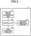
- FIG. 3 is a diagram illustrating the configuration of the controller 2 illustrated in FIG. 1 .
- the controller 2 includes a control signal transmission unit 21, a first communication unit 22, a second communication unit 23, and a control unit 24.
- the control signal transmission unit 21 has the function of transmitting, to the device 4 to be controlled, a control signal generated by the control unit 24 to be described below.
- the control signal transmission unit 21 can be configured by use of, for example, an infrared communication device.
- the first communication unit 22 is configured by use of a communication device and the like, and has the function of connecting to a communication path such as the Internet.
- the first communication unit 22 can communicate with the management server 1 via the communication path.
- the second communication unit 23 has the function of communicating with the wearable device 3 that is physically close to the controller 2.
- the second communication unit 23 can communicate with the wearable device 3 by using short-range wireless communication such as Bluetooth (registered trademark) or near field communication (NFC) .
- the control unit 24 acquires biometric information from the wearable device 3, and transmits the acquired biometric information to the management server 1 via the first communication unit 22.
- the control unit 24 is, for example, a microcontroller.
- the control unit 24 generates a control signal for controlling the device 4 to be controlled, based on an operating condition transmitted from the management server 1.
- the control unit 24 can transmit the generated control signal to the device 4 to be controlled, by using the control signal transmission unit 21.
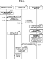
- FIG. 4 is a sequence diagram illustrating the operation of the device control system 100 illustrated in FIG. 1 .
- the example illustrated in FIG. 4 is based on the assumption that biometric information includes user-specific information that can be used for user authentication.
- the wearable device 3 periodically acquires biometric information on a user wearing the wearable device 3 (step S101).
- the wearable device 3 and the controller 2 perform a connection process (step S102).
- the wearable device 3 transmits the acquired biometric information to the controller 2 (step S103).
- the controller 2 receives the biometric information transmitted by the wearable device 3, and transmits the received biometric information to the management server 1 (step S104).
- the management server 1 receives the biometric information transmitted by the controller 2, the management server 1 performs user authentication by using the received biometric information (step S105).
- the management server 1 identifies a user whom the biometric information concerns, that is, the user of the wearable device 3, the management server 1 acquires personal data associated with the identified user from the database 12 (step S106).
- the management server 1 generates an operating condition of the device 4 to be controlled, based on the received biometric information and the acquired personal data (step S107).
- the management server 1 transmits the generated operating condition to the controller 2 (step S108).
- the controller 2 When the controller 2 receives the operating condition transmitted by the management server 1, the controller 2 generates a control signal for controlling the device 4 to be controlled, based on the received operating condition (step S109). The controller 2 transmits the generated control signal to the device 4 to be controlled (step S110). The device 4 to be controlled that has received the control signal operates based on the control signal.
- the operating condition of the device 4 to be controlled is generated based on personal data determined as a result of user authentication. It is thus possible to control the device 4 to be controlled in accordance with the preference of the user of the wearable device 3. Furthermore, according to the device control system 100, an operating condition is generated based on biometric information acquired by the wearable device 3. Therefore, it is possible to control the device 4 to be controlled, in accordance with the current state of the user.
- the controller 2 receives an operating condition from the management server 1, generates a control signal based on the received operating condition, and transmits the generated control signal to the device 4 to be controlled. Therefore, the device 4 to be controlled does not need to be connected to the management server 1. Accordingly, it is not necessary to add a function to the device 4 to be controlled, and it is thus possible to apply control to be performed by use of the wearable device 3 to a wide range of devices.
- the management server 1 performs user authentication by using biometric information acquired by the wearable device 3. Therefore, common information is used as information necessary for identifying a user and information indicating the state of the user. It is thus possible to reduce the amount of data exchange between the wearable device 3 and the controller 2 and the amount of data exchange between the controller 2 and the management server 1.
- personal data indicate a user's preference in accordance with the state of the user.
- the personal data indicate a preference that changes according to the value of biometric information of a user, and can indicate different values as, for example, temperatures set for an air conditioner that is the device 4 to be controlled in the case where the user's body temperature is equal to or higher than a threshold value and in the case where the user's body temperature is lower than the threshold value.
- the management server 1 can generate an operating condition based on the user's preference in accordance with the state of the user indicated by the biometric information, by using the biometric information and the personal data.
- the configuration set forth in the above embodiment shows an example of the subject matter of the present invention, and it is possible to combine the configuration with another technique that is publicly known, and is also possible to make omissions and changes to part of the configuration without departing from the gist of the present invention.
- the first embodiment has been described with an example in which the single wearable device 3 is used, it is also possible to use a plurality of the wearable devices 3 in the device control system 100.
- the controller 2 can also be configured such that the controller 2 determines the locations of the plurality of wearable devices 3, and generates control signals based on the locations of the wearable devices 3 and operating conditions generated corresponding to the users of the wearable devices 3.
Landscapes
- Engineering & Computer Science (AREA)
- Theoretical Computer Science (AREA)
- General Engineering & Computer Science (AREA)
- Computer Security & Cryptography (AREA)
- Physics & Mathematics (AREA)
- General Physics & Mathematics (AREA)
- Computer Hardware Design (AREA)
- Software Systems (AREA)
- Human Computer Interaction (AREA)
- Databases & Information Systems (AREA)
- Mechanical Engineering (AREA)
- Chemical & Material Sciences (AREA)
- Combustion & Propulsion (AREA)
- Library & Information Science (AREA)
- Data Mining & Analysis (AREA)
- Automation & Control Theory (AREA)
- Selective Calling Equipment (AREA)
- Telephonic Communication Services (AREA)
- Management, Administration, Business Operations System, And Electronic Commerce (AREA)
- User Interface Of Digital Computer (AREA)
- Air Conditioning Control Device (AREA)
Abstract
Description
- The present invention relates to a device control system that controls a device to be controlled.
- Heretofore, there has been a technique of using detection data acquired by use of a sensor when determining an operating condition of a device to be controlled, such as an air conditioner.
Patent Literature 1 discloses a technique which accurately determines a user's location by using the location of a mobile terminal held by the user and a detection value of a human detection sensor, and uses an operating condition preset for each specified user as an operating condition of a device to be controlled. The operating condition is preset according to the user's preference. - Patent Literature 1: Japanese Patent Application Laid-open No.
2015-61203 - However, the technique described in
Patent Literature 1 has a problem in that although it is possible to detect the movement of the user and determine an operating condition in accordance with the preference of the user by continuing to use an operating condition set before the movement, it is not possible to determine an operating condition in accordance with the current state of the user. - The present invention has been made in view of the above, and an object of the present invention is to obtain a device control system capable of determining the operating condition of a device to be controlled in accordance with a user's preference and the current state of the user.
- To solve the above problem and achieve an object, there is provided a device control system according to the present invention including: a device to be controlled; a wearable device to acquire biometric information on a user; a management server to determine personal data associated with the user of the wearable device when receiving the biometric information, and to generate an operating condition of the device to be controlled, based on the received biometric information and the determined personal data, the personal data being one of a plurality of pieces of personal data indicating a preference of each user regarding the operating condition of the device to be controlled; and a controller to generate a control signal for controlling the device to be controlled, based on the operating condition generated by the management server, and to transmit the generated control signal to the device to be controlled.
- A device control system according to the present invention has the effect of enabling determination of the operating condition of a device to be controlled in accordance with a user's preference and the state of the user.
-
-
FIG. 1 is a diagram illustrating the configuration of a device control system according to a first embodiment of the present invention. -
FIG. 2 is a diagram illustrating the configuration of a management server illustrated inFIG. 1 . -
FIG. 3 is a diagram illustrating the configuration of a controller illustrated inFIG. 1 . -
FIG. 4 is a sequence diagram illustrating the operation of the device control system illustrated inFIG. 1 . - Hereinafter, a device control system according to an embodiment of the present invention will be described in detail with reference to the drawings. Note that the present invention is not limited to the embodiment.
-
FIG. 1 is a diagram illustrating the configuration of adevice control system 100 according to a first embodiment of the present invention. Thedevice control system 100 includes amanagement server 1, controllers 2a and 2b, a wearable device 3, and devices 4a and 4b to be controlled. Hereinafter, when the controllers 2a and 2b are not distinguished from each other, the controllers 2a and 2b may be collectively referred to ascontrollers 2. Similarly, when the devices 4a and 4b to be controlled are not distinguished from each other, the devices 4a and 4b to be controlled may be collectively referred to as devices 4 to be controlled. - The controller 2a and the device 4a to be controlled are installed at a place A. The controller 2b and the device 4b to be controlled are installed at a place B. The wearable device 3 is a device to be worn by a user, and moves in accordance with the movement of the user.
- The
management server 1 is connected to the controllers 2a and 2b via a communication path such as the Internet. Themanagement server 1 is, for example, a cloud server, and can control the devices 4a and 4b to be controlled via the controllers 2a and 2b. - The
controller 2 is connected to the device 4 to be controlled that is previously associated with thecontroller 2. The connection between thecontroller 2 and the device 4 to be controlled may be wired or wireless connection. Thecontroller 2 can be wirelessly connected to the wearable device 3. Thecontroller 2 and the wearable device 3 are connected by short-range wireless communication. When the wearable device 3 is located within a distance that allows the wearable device 3 to communicate with thecontroller 2, thecontroller 2 and the wearable device 3 can communicate with each other. For example,FIG. 1 illustrates an example in which a user wearing the wearable device 3 is present in the place A. In this case, the wearable device 3 can communicate with the controller 2a. When the user of the wearable device 3 moves to the place B, the wearable device 3 can communicate with the controller 2b. - The wearable device 3 is a device that can be worn by a user, and has the function of acquiring biometric information on the user wearing the wearable device 3. The biometric information includes the amount of activity, the amount of sweat, a body temperature, a heart rate, and the like. The shape of the wearable device 3 is not limited as long as the wearable device 3 can be worn by a user. For example, the wearable device 3 is a wristwatch-type, glasses-type, clothes-type, or earphone-type device. Furthermore, the wearable device 3 transmits user-specific information to the
controller 2 for use in user authentication. The user-specific information may be a user identifier (ID), or may be biometric information in the case where the wearable device 3 can acquire user-specific biometric information. Examples of the user-specific biometric information include fingerprint information, iris information, a face image, vein pattern information, voice information, and retina information. When the user-specific information is a user ID, the wearable device 3 transmits, to thecontroller 2, a user ID stored in advance in the wearable device 3. When the user-specific information is biometric information, the wearable device 3 acquires user-specific biometric information, and transmits the acquired biometric information to thecontroller 2. - The device 4 to be controlled is controlled by the
controller 2. The device 4 to be controlled is a device having the function of changing the state of space, such as an air conditioner, a humidifier, a dehumidifier, or an air purifier. - Note that although an example of installing the
single controller 2 and the single device 4 to be controlled at each of the two places A and B has been cited inFIG. 1 , thedevice control system 100 is not limited to such an example. Themanagement server 1 can communicate with a plurality of thecontrollers 2 installed at three or more places. In addition, there is a one-to-one correspondence between thecontroller 2 and the device 4 to be controlled in the example illustrated inFIG. 1 . However, thecontroller 2 may be associated with two or more devices 4 to be controlled and serve the function of controlling the plurality of devices 4 to be controlled. -
FIG. 2 is a diagram illustrating the configuration of themanagement server 1 illustrated inFIG. 1 . Themanagement server 1 includes a communication unit 11, adatabase 12, and a control unit 13. - The communication unit 11 is configured by use of a communication device and the like, and has the function of connecting to the
controller 2 via the communication path. The communication unit 11 can transmit and receive data to and from thecontroller 2 via the communication path. - The
database 12 is configured by use of a storage device and the like, and holds, as personal data for each user, user identification information and user-specific preference information in association with each other. The personal data are not limited to specific data as long as the personal data include information indicating a user's preference regarding the setting of the device 4 to be controlled. Accordingly, the personal data may be, for example, accumulated data on past operating conditions, or may be user-specific information derived from the past operating conditions, to be referred to in determining the operating condition of the device 4 to be controlled. The personal data may be information indicating a user's preference in accordance with the user's state. The personal data may be information indicating, for example, a tendency such as being sensitive to heat or being sensitive to cold. Furthermore, the personal data are not limited to information based on the past operating conditions, but may be information set by the user itself. - The control unit 13 is configured by use of a central processing unit (CPU) and the like. The control unit 13 can acquire biometric information on the user from the
controller 2 via the communication unit 11, and determine personal data associated with the user of the wearable device 3. In the present embodiment, the control unit 13 determines personal data by performing user authentication by use of the biometric information acquired by the wearable device 3. Note that in the case where user identification information such as a user ID is stored in the wearable device 3 such that the wearable device 3 also transmits the identification information when transmitting biometric information to thecontroller 2, the control unit 13 can also perform user authentication by using the identification information. In the case where user authentication is performed by use of the user ID stored in the wearable device 3, the user needs to be registered in advance in the wearable device 3. In such a case, when the user uses the wearable device 3 of another user, it is not possible to correctly authenticate the user wearing the wearable device 3. Meanwhile, in the case where user authentication is performed by use of the biometric information acquired by the wearable device 3, it is possible to reliably authenticate the user wearing the wearable device 3. - Furthermore, the control unit 13 can generate the operating condition of the device 4 to be controlled, based on the biometric information on the user and the personal data. The control unit 13 can use the personal data to generate an operating condition in accordance with the preference of a user being present in a space in which the device 4 to be controlled is installed. The control unit 13 can also use the biometric information to generate the operating condition in accordance with the current state of the user being present in the device 4 to be controlled. The control unit 13 can transmit the operating condition to the
controller 2 via the communication unit 11. At this time, the control unit 13 returns the generated operating condition to thecontroller 2 which is the source of transmission of the biometric information. -
FIG. 3 is a diagram illustrating the configuration of thecontroller 2 illustrated inFIG. 1 . Thecontroller 2 includes a control signal transmission unit 21, a first communication unit 22, a second communication unit 23, and a control unit 24. - The control signal transmission unit 21 has the function of transmitting, to the device 4 to be controlled, a control signal generated by the control unit 24 to be described below. The control signal transmission unit 21 can be configured by use of, for example, an infrared communication device.
- The first communication unit 22 is configured by use of a communication device and the like, and has the function of connecting to a communication path such as the Internet. The first communication unit 22 can communicate with the
management server 1 via the communication path. The second communication unit 23 has the function of communicating with the wearable device 3 that is physically close to thecontroller 2. The second communication unit 23 can communicate with the wearable device 3 by using short-range wireless communication such as Bluetooth (registered trademark) or near field communication (NFC) . - When the second communication unit 23 establishes a connection with the wearable device 3, the control unit 24 acquires biometric information from the wearable device 3, and transmits the acquired biometric information to the
management server 1 via the first communication unit 22. The control unit 24 is, for example, a microcontroller. The control unit 24 generates a control signal for controlling the device 4 to be controlled, based on an operating condition transmitted from themanagement server 1. The control unit 24 can transmit the generated control signal to the device 4 to be controlled, by using the control signal transmission unit 21. -
FIG. 4 is a sequence diagram illustrating the operation of thedevice control system 100 illustrated inFIG. 1 . Note that the example illustrated inFIG. 4 is based on the assumption that biometric information includes user-specific information that can be used for user authentication. For example, the wearable device 3 periodically acquires biometric information on a user wearing the wearable device 3 (step S101). When the wearable device 3 approaches thecontroller 2, the wearable device 3 and thecontroller 2 perform a connection process (step S102). When connected to thecontroller 2, the wearable device 3 transmits the acquired biometric information to the controller 2 (step S103). - The
controller 2 receives the biometric information transmitted by the wearable device 3, and transmits the received biometric information to the management server 1 (step S104). When themanagement server 1 receives the biometric information transmitted by thecontroller 2, themanagement server 1 performs user authentication by using the received biometric information (step S105). When themanagement server 1 identifies a user whom the biometric information concerns, that is, the user of the wearable device 3, themanagement server 1 acquires personal data associated with the identified user from the database 12 (step S106). Themanagement server 1 generates an operating condition of the device 4 to be controlled, based on the received biometric information and the acquired personal data (step S107). Themanagement server 1 transmits the generated operating condition to the controller 2 (step S108). - When the
controller 2 receives the operating condition transmitted by themanagement server 1, thecontroller 2 generates a control signal for controlling the device 4 to be controlled, based on the received operating condition (step S109). Thecontroller 2 transmits the generated control signal to the device 4 to be controlled (step S110). The device 4 to be controlled that has received the control signal operates based on the control signal. - As described above, in the
device control system 100 according to the first embodiment of the present invention, the operating condition of the device 4 to be controlled is generated based on personal data determined as a result of user authentication. It is thus possible to control the device 4 to be controlled in accordance with the preference of the user of the wearable device 3. Furthermore, according to thedevice control system 100, an operating condition is generated based on biometric information acquired by the wearable device 3. Therefore, it is possible to control the device 4 to be controlled, in accordance with the current state of the user. - Moreover, according to the
device control system 100, thecontroller 2 receives an operating condition from themanagement server 1, generates a control signal based on the received operating condition, and transmits the generated control signal to the device 4 to be controlled. Therefore, the device 4 to be controlled does not need to be connected to themanagement server 1. Accordingly, it is not necessary to add a function to the device 4 to be controlled, and it is thus possible to apply control to be performed by use of the wearable device 3 to a wide range of devices. - In addition, according to the
device control system 100, themanagement server 1 performs user authentication by using biometric information acquired by the wearable device 3. Therefore, common information is used as information necessary for identifying a user and information indicating the state of the user. It is thus possible to reduce the amount of data exchange between the wearable device 3 and thecontroller 2 and the amount of data exchange between thecontroller 2 and themanagement server 1. - Furthermore, according to the
device control system 100, personal data indicate a user's preference in accordance with the state of the user. For example, the personal data indicate a preference that changes according to the value of biometric information of a user, and can indicate different values as, for example, temperatures set for an air conditioner that is the device 4 to be controlled in the case where the user's body temperature is equal to or higher than a threshold value and in the case where the user's body temperature is lower than the threshold value. In this case, themanagement server 1 can generate an operating condition based on the user's preference in accordance with the state of the user indicated by the biometric information, by using the biometric information and the personal data. - The configuration set forth in the above embodiment shows an example of the subject matter of the present invention, and it is possible to combine the configuration with another technique that is publicly known, and is also possible to make omissions and changes to part of the configuration without departing from the gist of the present invention.
- For example, although the first embodiment has been described with an example in which the single wearable device 3 is used, it is also possible to use a plurality of the wearable devices 3 in the
device control system 100. When a plurality of the wearable devices 3 are present in the same place and the device 4 to be controlled has the function of setting an operating condition for each air blowing direction, thecontroller 2 can also be configured such that thecontroller 2 determines the locations of the plurality of wearable devices 3, and generates control signals based on the locations of the wearable devices 3 and operating conditions generated corresponding to the users of the wearable devices 3. - 1 management server; 2, 2a, 2b controller; 3 wearable device; 4, 4a, 4b device to be controlled; 11 communication unit; 12 database; 13, 24 control unit; 21 control signal transmission unit; 22 first communication unit; 23 second communication unit; 100 device control system.
Claims (7)
- A device control system comprising:a device to be controlled;a wearable device to acquire biometric information on a user;a management server to determine personal data associated with the user of the wearable device, from among a plurality of pieces of personal data each indicating a preference of each user regarding an operating condition of the device to be controlled, when receiving the biometric information, and to generate an operating condition of the device to be controlled, based on the received biometric information and the determined personal data; anda controller to generate a control signal for controlling the device to be controlled, based on the operating condition generated by the management server, and to transmit the generated control signal to the device to be controlled.
- The device control system according to claim 1, wherein when detecting a connection with the wearable device, the controller acquires the biometric information from the wearable device, and transmits the acquired biometric information to the management server.
- The device control system according to claim 2, comprising
a plurality of the controllers, wherein
the management server transmits the operating condition to the controller that is a source of transmission of the received biometric information. - The device control system according to any one of claims 1 to 3, wherein
the device to be controlled is an air conditioner, and
the biometric information includes at least one of an amount of activity, an amount of sweat, a body temperature, and a heart rate. - The device control system according to any one of claims 1 to 4, wherein the management server determines the personal data by performing user authentication based on the biometric information acquired by the wearable device.
- The device control system according to any one of claims 1 to 5, wherein the personal data include information indicating past operating conditions accumulated in association with the user.
- The device control system according to claim 1, wherein
the personal data indicate a preference of a user in accordance with a state of the user, and
the management server generates the operating condition based on a preference of the user in accordance with a state of the user indicated by the biometric information.
Applications Claiming Priority (1)
| Application Number | Priority Date | Filing Date | Title |
|---|---|---|---|
| PCT/JP2018/021945 WO2019234899A1 (en) | 2018-06-07 | 2018-06-07 | Device control system |
Publications (2)
| Publication Number | Publication Date |
|---|---|
| EP3806001A1 true EP3806001A1 (en) | 2021-04-14 |
| EP3806001A4 EP3806001A4 (en) | 2021-07-07 |
Family
ID=68769760
Family Applications (1)
| Application Number | Title | Priority Date | Filing Date |
|---|---|---|---|
| EP18922022.1A Withdrawn EP3806001A4 (en) | 2018-06-07 | 2018-06-07 | DEVICE CONTROL SYSTEM |
Country Status (6)
| Country | Link |
|---|---|
| US (1) | US20210232669A1 (en) |
| EP (1) | EP3806001A4 (en) |
| JP (1) | JP7034278B2 (en) |
| CN (1) | CN112204924A (en) |
| AU (2) | AU2018426445A1 (en) |
| WO (1) | WO2019234899A1 (en) |
Families Citing this family (2)
| Publication number | Priority date | Publication date | Assignee | Title |
|---|---|---|---|---|
| WO2021245886A1 (en) * | 2020-06-04 | 2021-12-09 | 三菱電機株式会社 | Traffic management system for building |
| CN114704931B (en) * | 2022-03-28 | 2024-07-12 | 青岛海尔空调器有限总公司 | Control method and device of multi-link air conditioner |
Family Cites Families (15)
| Publication number | Priority date | Publication date | Assignee | Title |
|---|---|---|---|---|
| WO2008051461A2 (en) * | 2006-10-20 | 2008-05-02 | Skinvisible Pharmaceuticals, Inc. | Acne treatment composition and methods for using |
| JP5121616B2 (en) * | 2008-07-24 | 2013-01-16 | 三菱電機ビルテクノサービス株式会社 | Building facilities remote management system |
| JP6158306B2 (en) | 2013-03-25 | 2017-07-05 | 株式会社東芝 | Wearable device and remote control method |
| JP6024630B2 (en) | 2013-09-19 | 2016-11-16 | 三菱電機株式会社 | Centralized management device, human body position detection system, and device control system |
| US9721409B2 (en) * | 2014-05-02 | 2017-08-01 | Qualcomm Incorporated | Biometrics for user identification in mobile health systems |
| JP2016010047A (en) | 2014-06-25 | 2016-01-18 | 三菱電機株式会社 | Apparatus control system, home apparatus, and remote operation terminal |
| US20160061472A1 (en) * | 2014-09-02 | 2016-03-03 | Samsung Electronics Co., Ltd. | Method and device for controlling room temperature and humidity |
| KR102247518B1 (en) * | 2014-12-23 | 2021-05-03 | 삼성전자주식회사 | Wearable apparatus, management server, management system having the same and method for controlling thereof |
| JP2016142415A (en) * | 2015-01-29 | 2016-08-08 | 株式会社東芝 | Air-conditioning control device, server device, air-conditioning control system, air-conditioning control method, and air-conditioning control program |
| CN107427230A (en) * | 2015-02-05 | 2017-12-01 | Mc10股份有限公司 | For the method and system with environmental interaction |
| JP2017062060A (en) | 2015-09-24 | 2017-03-30 | アイシン精機株式会社 | Environmental condition control system |
| KR102587452B1 (en) * | 2015-12-09 | 2023-10-11 | 삼성전자주식회사 | Scheme for controlling equipment based on biological information |
| JP2017152817A (en) | 2016-02-23 | 2017-08-31 | 住友電気工業株式会社 | Apparatus control device and apparatus control program |
| US10393397B2 (en) * | 2016-06-24 | 2019-08-27 | International Business Machines Corporation | Dynamic climate control adjustment system |
| WO2018051461A1 (en) * | 2016-09-15 | 2018-03-22 | 三菱電機株式会社 | Equipment control device, equipment control system, equipment control method, and program |
-
2018
- 2018-06-07 US US17/053,873 patent/US20210232669A1/en not_active Abandoned
- 2018-06-07 JP JP2020523944A patent/JP7034278B2/en active Active
- 2018-06-07 WO PCT/JP2018/021945 patent/WO2019234899A1/en not_active Ceased
- 2018-06-07 CN CN201880093879.5A patent/CN112204924A/en active Pending
- 2018-06-07 EP EP18922022.1A patent/EP3806001A4/en not_active Withdrawn
- 2018-06-07 AU AU2018426445A patent/AU2018426445A1/en not_active Abandoned
-
2022
- 2022-09-07 AU AU2022228136A patent/AU2022228136B2/en active Active
Also Published As
| Publication number | Publication date |
|---|---|
| AU2022228136A1 (en) | 2022-09-29 |
| WO2019234899A1 (en) | 2019-12-12 |
| AU2018426445A1 (en) | 2020-11-26 |
| JP7034278B2 (en) | 2022-03-11 |
| CN112204924A (en) | 2021-01-08 |
| EP3806001A4 (en) | 2021-07-07 |
| JPWO2019234899A1 (en) | 2020-12-17 |
| AU2022228136B2 (en) | 2023-11-23 |
| US20210232669A1 (en) | 2021-07-29 |
Similar Documents
| Publication | Publication Date | Title |
|---|---|---|
| CN113639446B (en) | Method and device for controlling air conditioner, air conditioner and storage medium | |
| AU2022228136B2 (en) | Device control system | |
| CN111823811B (en) | Temperature environment adjustment system, temperature preference estimation system, and non-transitory computer readable medium | |
| US20190158305A1 (en) | Technologies for optimally individualized building automation | |
| US9329695B2 (en) | Wearable terminal and method for controlling the same | |
| US20160131383A1 (en) | Group dynamic environment control | |
| EP3190748B1 (en) | Illumination system and control method thereof | |
| US20240205584A1 (en) | Ear-wearable devices for control of other devices and related methods | |
| KR20210042603A (en) | Smart safety helmet operation system | |
| US10935265B2 (en) | Biometric air conditioning control system | |
| KR20140146366A (en) | Method for communication using wearable device and wearable device enabling the method | |
| KR102594947B1 (en) | Electronic device for providing meditation contents and operating method thereof | |
| US20140089007A1 (en) | Device to user association in physiological sensor systems | |
| US20190110140A1 (en) | Body-Worn Personal Device with Pairing Control | |
| KR20170114356A (en) | Electronic device and controling method thereof | |
| EP3817314B1 (en) | Method and communication devices for extending log-in to multiple communication devices | |
| KR20200137919A (en) | Electronic device for controlling a skin care device and method of operating the same | |
| CN109747568B (en) | Method and device for controlling internet of things equipment linked with vehicle | |
| WO2019053399A1 (en) | System and method for contact less control of an appliance technical field | |
| CN108679786B (en) | Air conditioner control method and device based on intelligent wearable equipment | |
| JP7149069B2 (en) | Portable information terminal, sensor, biological information management method, biological information processing program, and computer-readable storage medium | |
| JP2018078428A (en) | Control information output system, device control system, device control method, and program | |
| KR102033817B1 (en) | Air conditioning system using human body heat capacity and a conditioning method for an air conditioning system | |
| KR20160059793A (en) | Apparatus and Method for Vehicle Controlling of Using User Authentication | |
| CN106293033B (en) | Information processing method and electronic equipment |
Legal Events
| Date | Code | Title | Description |
|---|---|---|---|
| STAA | Information on the status of an ep patent application or granted ep patent |
Free format text: STATUS: THE INTERNATIONAL PUBLICATION HAS BEEN MADE |
|
| PUAI | Public reference made under article 153(3) epc to a published international application that has entered the european phase |
Free format text: ORIGINAL CODE: 0009012 |
|
| STAA | Information on the status of an ep patent application or granted ep patent |
Free format text: STATUS: REQUEST FOR EXAMINATION WAS MADE |
|
| 17P | Request for examination filed |
Effective date: 20201126 |
|
| AK | Designated contracting states |
Kind code of ref document: A1 Designated state(s): AL AT BE BG CH CY CZ DE DK EE ES FI FR GB GR HR HU IE IS IT LI LT LU LV MC MK MT NL NO PL PT RO RS SE SI SK SM TR |
|
| AX | Request for extension of the european patent |
Extension state: BA ME |
|
| A4 | Supplementary search report drawn up and despatched |
Effective date: 20210608 |
|
| RIC1 | Information provided on ipc code assigned before grant |
Ipc: G06Q 10/00 20120101AFI20210601BHEP Ipc: G06F 16/909 20190101ALI20210601BHEP Ipc: G06F 21/32 20130101ALI20210601BHEP Ipc: G06K 9/00 20060101ALI20210601BHEP Ipc: G05B 19/409 20060101ALI20210601BHEP |
|
| DAV | Request for validation of the european patent (deleted) | ||
| DAX | Request for extension of the european patent (deleted) | ||
| STAA | Information on the status of an ep patent application or granted ep patent |
Free format text: STATUS: EXAMINATION IS IN PROGRESS |
|
| 17Q | First examination report despatched |
Effective date: 20241125 |
|
| STAA | Information on the status of an ep patent application or granted ep patent |
Free format text: STATUS: THE APPLICATION HAS BEEN WITHDRAWN |
|
| 18W | Application withdrawn |
Effective date: 20250218 |