EP3805539B1 - Aircraft bleed air systems and methods - Google Patents
Aircraft bleed air systems and methods Download PDFInfo
- Publication number
- EP3805539B1 EP3805539B1 EP20201413.0A EP20201413A EP3805539B1 EP 3805539 B1 EP3805539 B1 EP 3805539B1 EP 20201413 A EP20201413 A EP 20201413A EP 3805539 B1 EP3805539 B1 EP 3805539B1
- Authority
- EP
- European Patent Office
- Prior art keywords
- engine
- gas turbine
- turbine engine
- switching valve
- air
- Prior art date
- Legal status (The legal status is an assumption and is not a legal conclusion. Google has not performed a legal analysis and makes no representation as to the accuracy of the status listed.)
- Active
Links
- 238000000034 method Methods 0.000 title claims description 60
- 230000008859 change Effects 0.000 claims description 43
- 230000009471 action Effects 0.000 claims description 23
- 230000004044 response Effects 0.000 claims description 13
- 238000004891 communication Methods 0.000 claims description 9
- 230000007257 malfunction Effects 0.000 claims description 8
- 230000000740 bleeding effect Effects 0.000 claims 2
- 239000003570 air Substances 0.000 description 133
- 239000007789 gas Substances 0.000 description 29
- 238000001816 cooling Methods 0.000 description 8
- 239000000446 fuel Substances 0.000 description 8
- 238000011065 in-situ storage Methods 0.000 description 6
- 239000012080 ambient air Substances 0.000 description 4
- 230000005540 biological transmission Effects 0.000 description 4
- 239000000567 combustion gas Substances 0.000 description 4
- 238000007789 sealing Methods 0.000 description 4
- 238000005516 engineering process Methods 0.000 description 3
- 238000012544 monitoring process Methods 0.000 description 3
- 238000013459 approach Methods 0.000 description 1
- 239000007853 buffer solution Substances 0.000 description 1
- 238000002485 combustion reaction Methods 0.000 description 1
- 238000013461 design Methods 0.000 description 1
- 230000009977 dual effect Effects 0.000 description 1
- 230000000694 effects Effects 0.000 description 1
- RLQJEEJISHYWON-UHFFFAOYSA-N flonicamid Chemical compound FC(F)(F)C1=CC=NC=C1C(=O)NCC#N RLQJEEJISHYWON-UHFFFAOYSA-N 0.000 description 1
- 238000010438 heat treatment Methods 0.000 description 1
- 230000006872 improvement Effects 0.000 description 1
- 230000000977 initiatory effect Effects 0.000 description 1
- 239000007788 liquid Substances 0.000 description 1
- 238000012423 maintenance Methods 0.000 description 1
- 230000014759 maintenance of location Effects 0.000 description 1
- 239000000203 mixture Substances 0.000 description 1
- 238000012986 modification Methods 0.000 description 1
- 230000004048 modification Effects 0.000 description 1
- 230000009467 reduction Effects 0.000 description 1
- 238000012552 review Methods 0.000 description 1
- 238000012360 testing method Methods 0.000 description 1
- 238000012549 training Methods 0.000 description 1
- 238000011144 upstream manufacturing Methods 0.000 description 1
Images


Classifications
-
- F—MECHANICAL ENGINEERING; LIGHTING; HEATING; WEAPONS; BLASTING
- F02—COMBUSTION ENGINES; HOT-GAS OR COMBUSTION-PRODUCT ENGINE PLANTS
- F02C—GAS-TURBINE PLANTS; AIR INTAKES FOR JET-PROPULSION PLANTS; CONTROLLING FUEL SUPPLY IN AIR-BREATHING JET-PROPULSION PLANTS
- F02C9/00—Controlling gas-turbine plants; Controlling fuel supply in air- breathing jet-propulsion plants
- F02C9/16—Control of working fluid flow
-
- F—MECHANICAL ENGINEERING; LIGHTING; HEATING; WEAPONS; BLASTING
- F02—COMBUSTION ENGINES; HOT-GAS OR COMBUSTION-PRODUCT ENGINE PLANTS
- F02C—GAS-TURBINE PLANTS; AIR INTAKES FOR JET-PROPULSION PLANTS; CONTROLLING FUEL SUPPLY IN AIR-BREATHING JET-PROPULSION PLANTS
- F02C6/00—Plural gas-turbine plants; Combinations of gas-turbine plants with other apparatus; Adaptations of gas-turbine plants for special use
- F02C6/04—Gas-turbine plants providing heated or pressurised working fluid for other apparatus, e.g. without mechanical power output
- F02C6/06—Gas-turbine plants providing heated or pressurised working fluid for other apparatus, e.g. without mechanical power output providing compressed gas
- F02C6/08—Gas-turbine plants providing heated or pressurised working fluid for other apparatus, e.g. without mechanical power output providing compressed gas the gas being bled from the gas-turbine compressor
-
- F—MECHANICAL ENGINEERING; LIGHTING; HEATING; WEAPONS; BLASTING
- F02—COMBUSTION ENGINES; HOT-GAS OR COMBUSTION-PRODUCT ENGINE PLANTS
- F02C—GAS-TURBINE PLANTS; AIR INTAKES FOR JET-PROPULSION PLANTS; CONTROLLING FUEL SUPPLY IN AIR-BREATHING JET-PROPULSION PLANTS
- F02C6/00—Plural gas-turbine plants; Combinations of gas-turbine plants with other apparatus; Adaptations of gas-turbine plants for special use
- F02C6/02—Plural gas-turbine plants having a common power output
-
- F—MECHANICAL ENGINEERING; LIGHTING; HEATING; WEAPONS; BLASTING
- F02—COMBUSTION ENGINES; HOT-GAS OR COMBUSTION-PRODUCT ENGINE PLANTS
- F02C—GAS-TURBINE PLANTS; AIR INTAKES FOR JET-PROPULSION PLANTS; CONTROLLING FUEL SUPPLY IN AIR-BREATHING JET-PROPULSION PLANTS
- F02C7/00—Features, components parts, details or accessories, not provided for in, or of interest apart form groups F02C1/00 - F02C6/00; Air intakes for jet-propulsion plants
- F02C7/12—Cooling of plants
- F02C7/16—Cooling of plants characterised by cooling medium
- F02C7/18—Cooling of plants characterised by cooling medium the medium being gaseous, e.g. air
-
- F—MECHANICAL ENGINEERING; LIGHTING; HEATING; WEAPONS; BLASTING
- F02—COMBUSTION ENGINES; HOT-GAS OR COMBUSTION-PRODUCT ENGINE PLANTS
- F02C—GAS-TURBINE PLANTS; AIR INTAKES FOR JET-PROPULSION PLANTS; CONTROLLING FUEL SUPPLY IN AIR-BREATHING JET-PROPULSION PLANTS
- F02C9/00—Controlling gas-turbine plants; Controlling fuel supply in air- breathing jet-propulsion plants
- F02C9/16—Control of working fluid flow
- F02C9/18—Control of working fluid flow by bleeding, bypassing or acting on variable working fluid interconnections between turbines or compressors or their stages
-
- F—MECHANICAL ENGINEERING; LIGHTING; HEATING; WEAPONS; BLASTING
- F05—INDEXING SCHEMES RELATING TO ENGINES OR PUMPS IN VARIOUS SUBCLASSES OF CLASSES F01-F04
- F05D—INDEXING SCHEME FOR ASPECTS RELATING TO NON-POSITIVE-DISPLACEMENT MACHINES OR ENGINES, GAS-TURBINES OR JET-PROPULSION PLANTS
- F05D2220/00—Application
- F05D2220/30—Application in turbines
- F05D2220/32—Application in turbines in gas turbines
- F05D2220/329—Application in turbines in gas turbines in helicopters
-
- F—MECHANICAL ENGINEERING; LIGHTING; HEATING; WEAPONS; BLASTING
- F05—INDEXING SCHEMES RELATING TO ENGINES OR PUMPS IN VARIOUS SUBCLASSES OF CLASSES F01-F04
- F05D—INDEXING SCHEME FOR ASPECTS RELATING TO NON-POSITIVE-DISPLACEMENT MACHINES OR ENGINES, GAS-TURBINES OR JET-PROPULSION PLANTS
- F05D2260/00—Function
- F05D2260/80—Diagnostics
-
- F—MECHANICAL ENGINEERING; LIGHTING; HEATING; WEAPONS; BLASTING
- F05—INDEXING SCHEMES RELATING TO ENGINES OR PUMPS IN VARIOUS SUBCLASSES OF CLASSES F01-F04
- F05D—INDEXING SCHEME FOR ASPECTS RELATING TO NON-POSITIVE-DISPLACEMENT MACHINES OR ENGINES, GAS-TURBINES OR JET-PROPULSION PLANTS
- F05D2260/00—Function
- F05D2260/83—Testing, e.g. methods, components or tools therefor
-
- F—MECHANICAL ENGINEERING; LIGHTING; HEATING; WEAPONS; BLASTING
- F05—INDEXING SCHEMES RELATING TO ENGINES OR PUMPS IN VARIOUS SUBCLASSES OF CLASSES F01-F04
- F05D—INDEXING SCHEME FOR ASPECTS RELATING TO NON-POSITIVE-DISPLACEMENT MACHINES OR ENGINES, GAS-TURBINES OR JET-PROPULSION PLANTS
- F05D2270/00—Control
- F05D2270/30—Control parameters, e.g. input parameters
- F05D2270/303—Temperature
Definitions
- the disclosure relates to aircraft bleed air systems and methods.
- Bleed air produced by a gas turbine engine is compressed air from the compressor stage that is used for engine functions (such as cooling of turbines and to help seal bearing cavities, for example) and is also used for aircraft functions (such as engine starting, anti-icing, cabin pressure, cabin heating, pneumatic systems, pressurizing liquid tanks, etc.).
- Engine bleed air can be derived from the high pressure or the low pressure compressor stage, depending on the air pressure and temperature requirements and the engine operating condition. Low pressure stage air is typically used during high power engine operation, and high pressure stage air may be used during descent and other low power engine operations.
- Bleed air may be used within an engine for engine functions such as bearing cavity sealing and cooling of various engine components. While existing bleed air systems may be suitable for their intended purposes, improvement to the prior art is desirable.
- WO 2013/154630 A1 discloses a gas turbine engine buffer system
- US 2018/128176 A1 discloses an intercooled integrated air cycle machine
- US 2016/369695 A1 discloses a temperature-modulated recuperated gas turbine engine.
- the first action includes generating an indication that the switching valve is in a functional state.
- the second action includes generating an indication that the switching valve is in a malfunction state.
- the temperature is an inter-turbine temperature of the gas turbine engine.
- the temperature is an inter-turbine temperature of the gas turbine engine.
- control system is configured to prevent the switching the second engine between the powered mode and the standby mode in response to determining that the temperature change is below the threshold.
- Fig. 1A depicts an exemplary multi-engine aircraft 1, which in this case is a helicopter.
- the aircraft 1 may however also be a fixed-wing aircraft.
- the aircraft 1 includes at least two gas turbine engines 10, labeled in Figure 1A as "ENGINE 1" and "ENGINE 2". These two engines may be interconnected, in the case of the depicted helicopter application, by a common gearbox to form a multi-engine system 50 as shown in Fig. 1B .
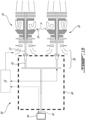
- Fig. 1B illustrates a schematic representation of an exemplary multi-engine system 50 that may be used as a power plant for the aircraft 1.
- the multi-engine system 50 comprises two or more gas turbine engines 10.
- the multi-engine system 50 may manage the operation of the engines 10, as will be described in further detail below.
- the multi-engine system 50 may be used as a dual engine powerplant for an aircraft, such as a helicopter. In addition to airborne applications, the multi-engine system 50 may be used in marine and/or industrial applications.
- the multi-engine system 50 of this embodiment includes first and second turboshaft engines 10 each having a respective transmission 38 which are interconnected by a common output gearbox 40 to drive a common load 44.
- the common load 44 may comprise a rotary wing of a rotary-wing aircraft.
- the common load 44 may be a main rotor of the helicopter 1.
- each of turboshaft engines 10 may be drivingly coupled to the common load 44 via the output gearbox 40, which may be of the speed-reduction type.
- the gear box 40 may have a plurality of transmission shafts 42 to receive mechanical energy from respective output shafts 11 of respective turboshaft engines 10.
- the gear box 40 may be configured to direct at least some of the combined mechanical energy from the plurality of the turboshaft engines 10 toward a common output shaft 42 for driving the common load 44 at a suitable operating (e.g., rotational) speed.
- the multi-engine system 50 may also be configured, for example, to drive accessories and/or other elements of an associated aircraft.
- the gear box 40 may be configured to permit the common load 44 to be driven by either of the turboshaft engines 100 or, by a combination of both engines 10 together.
- the gas turbine engine 10 is of a type provided, in one embodiment, for use in subsonic flight, generally comprising in serial flow communication a compressor section 9 for pressurizing the air, a combustor 8 in which the compressed air is mixed with fuel and ignited for generating an annular stream of hot combustion gases, and a turbine section 5 for extracting energy from the combustion gases.
- the engine 10 depicted in Fig. 2 is a turboshaft gas turbine engine, and therefore includes a reduction gearbox and transmission 38 with an output shaft 42 which is configured to provide power output from the engine 10 to the common aircraft gearbox 40 of the multi-engine system 50 of Fig. 1B .
- the present disclosure may also be applicable to other types of gas turbine engines, including turboprops and turbofans for example.
- the gas turbine engine 10 includes an air inlet 2 via which air enters the engine 10 before being directed into the compressor section 9 of the engine.
- the compressor section 9 includes a lowpressure axial compressor 12 and a high-pressure centrifugal compressor 13.
- Compressed air exits the high pressure compressor 13 through a diffuser 6 and is contained within a plenum 7 that surrounds the combustor 8.
- Fuel is supplied to the combustor 8 through fuel nozzles fed by a fuel system, wherein the injected fuel from the fuel nozzles is mixed with the compressed air within the combustor 8 thereby causing the fuel-air mixture to be ignited within the combustion chamber.
- a portion of the compressed air within the plenum 7 is therefore admitted into the combustor 8 through orifices in the side walls to create a cooling air curtain along the combustor walls.
- a portion of the compressed air is also is used as bleed air for pneumatic systems within and/or external to the engine.
- the annular stream of hot combustion gases exiting the combustor 8 is directed to a downstream turbine section 5 for extracting energy from the combustion gases before exiting the engine as exhaust.
- the turbine section 5 may include one or more turbine rotors.
- a high pressure turbine 4 drives a high pressure engine shaft to which both the low and high pressure compressors 12 and 13 are connected for driving same
- a low pressure turbine 3 drives a low pressure turbine shaft which is coaxial with the low pressure engine shaft and drives the power output shaft 11, and the gearbox 38, of the engine 10.
- Figures 3 to 5 show axial sectional views of the compressor section 9 of the gas turbine engine 10, in particular the low pressure axial compressor(s) 12 and high pressure centrifugal compressor 13. While the exemplary embodiment includes an axial compressor and a centrifugal compressor, it is to be understood that other configurations (e.g. two or more axial compressors, two or more centrifugal compressors, a different combination of the two, etc.) is also possible.
- the present description relates generally to operating a multi-engine aircraft 1, where a first engine of the gas turbine engines 10 is capable of providing motive power in flight to the aircraft 1 when operating in a "powered mode", and a second engine of the gas turbine engines 10 can be switched between a powered mode, whereby the second engine also provides motive power to the aircraft, and a lowerpower "standby mode", whereby substantially no (or very little) motive power is provide to the aircraft.
- the second engine may therefore be switched into, and maintained in, this very low-power standby mode during flight.
- the low-power standby mode of the second engine includes, but is not limited to a significantly reduced power mode or a so-called "sub-idle" mode in this example.
- fuel consumption of the second engine, and therefore over the overall powerplant is reduced.
- the second engine however remains able to return to normal operational power (e.g. full power) if additional power needed by the aircraft.
- the first engine 1 as described herein may be referred to as a "main” or “primary” engine, and the second engine 2 may be referred to herein as a “reserve” engine. However, it is to be understood that both are capable of operating a full power if desired/necessary.
- the second engine 10 of the aircraft 1 has a compressed air switching system 30 that comprises and is in communication with a switching valve 14.
- the switching valve 14 may also be referred to herein as an "input selector switch" 14.
- the compressed air switching system 30 may be controlled by the engine control system 31, such as a full-authority digital engine control (FADEC) system for example.
- the input selector switch 14 has three main components, namely, a manifold 15, a check valve 16, and a solenoid valve 17.
- the manifold 15 has a low pressure inlet 18 including the check valve 16 in communication with a low pressure air plenum 19.
- the manifold 15 has a high pressure inlet 20 including the solenoid valve 17 in communication with a high pressure air conduit 21, derived from the output of the high pressure centrifugal compressor 13.
- the manifold 15 conveys low or high pressure air via a manifold outlet 22 in communication with a bleed air system 27 of the engine 10 and aircraft 1.
- the bleed air system 27 supplies bleed air that it receives from the compressor section 9 to a plurality of parts of the engine 10, such as to various bearing and/or seal cavities, etc.
- the particular parts that the bleed air system 27 may be configured to provide with bleed air may depend on each particular embodiment of the bleed air system 27 and/or the engine 10 and/or the aircraft 1. In some embodiments, the bleed air system 27 may be conventional.
- switching valve 14 In the example shown, the combination of the manifold 15, check valve 16, and solenoid valve 17 form the switching valve 14.
- Other configurations of switching valve 14 will be apparent to those skilled in the art including a poppet valve, a sliding spool valve or a ball valve.
- Figure 4 shows the switching valve 14, and thus the compressed air switching system 30, in the powered (or "motive") mode and a powered position, respectively, where the solenoid valve 17 is closed and the check valve 16 is open, thereby connecting the low pressure inlet 18 and the switch outlet 22.
- the low pressure air from the plenum 19 is provided through the manifold 15 into the switch outlet 22.
- Figure 5 shows the switching valve 14, and thus the compressed air switching system 30, in the standby mode and a standby position, respectively, where the solenoid valve 17 is open and the check valve 16 is closed, thereby connecting the high pressure inlet 20 and the switch outlet 22.
- the high pressure air from the high pressure air conduit 21 is provided through the manifold 15 into the switch outlet 22.
- low pressure compressed air is provided to the bleed air system (i.e. the secondary air system) for an engine operation system via the switch outlet 22.
- a compressed air passage 23 from the switch outlet 22 leads to an engine shaft 24 wherein the compressed air passage 23 passes through a stationary strut 25 within the gas path.
- the engine When the input selector switch 14 is in the powered mode of Figure 4 , the engine is operating in a normal flight condition at high power levels to provide a relatively high degree of motive power to the aircraft.
- a relatively high quantity of compressed bleed air is provided from the low pressure air plenum 19.
- the bleed air in the powered mode is provided to the aircraft operation system at sufficient pressure and quantity for aircraft functions such as cabin pressurization, engine starting, pneumatic systems etc. as well as for the engine operating system to maintain engine functions such as cooling the turbines 11 and maintaining oil seals.
- the second engine power output is less than the first engine power output.
- the first engine provides at least 2 times more power output than the second engine.
- the second engine power output may also be such that a power differential, i.e. a difference between the first engine power and the second engine power, as a percentage of the first engine power, is at least 20%.
- This differential power between the two engines may however be much greater, for example 40%, 60%, 90%, 95% or greater. Accordingly, in certain embodiments, the power output differential is between 20-95%, or alternately between 40-95%, or alternately still greater than 90%.
- the standby engine may be decoupled from the main transmission to provide zero motive power to the aircraft, and in such cases the power output differential is 100%.
- the gas generator speed of the second engine may however not correspond to the reduced power output of the second engine.
- the power output of the engine may be controlled by other means, such as by controlling variable guide vanes, and thus the gas generator speed of the second engine may be controlled in some embodiments and/or applications to approach that of the first engine during operation for example, even when the abovenoted power output differentials remain.
- the solenoid valve 17 is in electric communication with the engine control system 31 that includes sensing the second engine power output and the first engine power output. A comparison is made and a motive power output differential is determined. When the motive power output differential is below a threshold value the control system 31 communicates an open signal to the solenoid actuated valve 17.
- the solenoid valve 17 When the motive power output differential is reduced below the threshold value, the solenoid valve 17 is actuated to raise the manifold air pressure in the manifold 15 above the air pressure of the low pressure air source 19 which automatically closes the (normally open) one way check valve 16. As a result the switching valve 14 is switched between the powered mode and the standby mode depending on the signal received from the control system 31 and power output sensors.
- the control system 31 can control the second engine power output by controlling a plurality of variable guide vanes. While controlling the second engine operation during the standby mode, the rotational speed of the second engine can be maintained in the range of 40-70% of the rotational speed of the first engine, while controlling the variable guide vanes to increase or decrease the second engine power output.
- the method of operating the multi-engine aircraft during flight provides adequate compressed air to the second engine for the engine operation system uses, for example to actuate an air pressure operated oil retention seal, to cool an air cooled engine component, or to cool a turbine.
- the switching valve 14 receives air from the low pressure air plenum 19 or the high pressure air conduit 21.
- the present description provides a method of operating an aircraft propulsion gas turbine engine in a multi-engine aircraft, by operating at least one second engine in a powered mode to provide motive power in flight to the aircraft and supplying compressor pressure bleed air to the engine and aircraft, and while in flight operating the second engine in an standby mode to provide little or no motive power to the aircraft, switching to higher pressure bleed air source to provide second engine bleed air while substantially ceasing to supply bleed air to the aircraft.
- the present disclosure includes a method of operating a gas turbine engine including supplying "P2.X” air to pressurize seals and, when engine speed drops below a threshold, switching to higher pressure air source.
- An air switching system for a secondary air system of a gas turbine engine is therefore provided, which may include a solenoid operated shut off valve, which actuates to switch between first and second bleed air sources, and a check valve.
- the solenoid valve can be opened and closed, to respectively permit or block higher pressure air (e.g. "P3" air) from being directed to the compressor cavities for cooling and/or sealing purposes.
- higher pressure air e.g. "P3" air
- the solenoid valve is closed and the check valve is open, thereby permitting lower pressure air (e.g.
- P2.8 air to be fed to the compressor cavities for sealing and/or cooling purposes.
- the solenoid valve When the engine is operating in a standby mode with a lower power/speed range (e.g. a "sub-idle” operation as described herein), the solenoid valve is open and the check valve is closed, thereby forcing the higher pressure P3 air to be fed to the compressor cavities for sealing and/or cooling purposes.
- higher pressure P3 air can be used during sub-idle engine conditions in order to ensure proper engine operation, and switching between the two air system configurations is possible when desired due to the solenoid driven switching valve.
- the lowest pressure air source that is sufficient to ensure optimal engine operation at that operating condition can be selected by the present air switching system. This may be done for various different engine operating ranges/conditions, to ensure optimal engine operation.
- the present technology further provides methods of determining a state, such as a functioning state or a malfunction state, of the switching valve 14. In some embodiments, these methods may be applied to other types of valves in aircraft, and in methods of operating multi-engine aircraft for example, as described next.
- the control system 31 may be configured to execute the methods or at least one or more of the steps thereof. It is contemplated that any suitable combination of controllers, sensors and programming of the control system 31 for example, may be used to suit each embodiment and application of the methods and sequences thereof.
- the method 60 may include a step 62 of receiving a command from an operator, such as a pilot, of the aircraft 1 requesting to switch for example the second engine 2 to the standby mode. In some embodiments, the step 62 may be performed when the second engine 2 is operating in the powered mode.
- the method 60 may further include a step 64 of initiating a sequence, which may be referred to as a "switching valve test".
- the switching valve 14 may be in its powered position, in which the switching valve 14 supplies bleed air to the bleed air system 27, and hence to a plurality of parts of the second engine 2, from the low pressure air plenum 19.
- the low pressure air plenum 19 may be referred to as a first bleed location in / of the compressor section 9 of the engine 10.
- the low pressure air plenum 19 may be fluidly connected to a point in between two or more rotors of the compressor section 9, upstream of an outlet of the compressor section 9, to receive bleed air from that point.
- the method 60 may include a step 66 of determining one or more operating parameters of the engine 10.
- the one or more operating parameters of the engine 10 is a single parameter, which is a temperature of the engine 10. More particularly, the temperature is in a main gas path (labeled at (AF) in Fig. 3 ) of the engine 10 at a location at or downstream of the combustor 8. The temperature may be determined / monitored using any suitable methods and/or sensor(s) / hardware selected to suit the particular application(s) and embodiment of the engine 10.
- the temperature is an inter-turbine temperature (ITT) determined at a location between at least two turbine rotors / turbines of the turbine section 5 as shown schematically in Figure 3 .
- the inter-turbine temperature (ITT) may be determined using any suitable method, for example such as described in the commonly owned United States Patent Application No. 16/551,161, filed on August 26, 2019 , entitled "SYSTEM AND METHOD FOR MONITORING TEMPERATURE OF A GAS TURBINE ENGINE. It is contemplated that the inter-turbine temperature (ITT) may also be determined using other methods, such as using a conventional one or more methods.
- the temperature used in the method 60 may be a temperature taken downstream of the turbine(s) of the engine 10, such as an exhaust gas temperature (EGT) of the engine 10.
- the method 60 may proceed with a step 68 of actuating the switching valve 14 of the compressed air switching system 30.
- the step 68 actuates the switching valve 14 to bleed air from the high pressure air conduit 21.
- the high pressure air conduit 21 may be fluidly connected to a point in, or simply to, an outlet of the compressor section 9, to provide a higher pressure bleed air than is available at low pressure inlet 18 of the switching valve 14 and the low pressure air plenum 19.
- the point at which the high pressure air conduit 21 fluidly connects to the outlet of the compressor section 9 may be referred to as a second bleed location in / of the compressor section 9 of the engine 10, which is downstream of the first bleed location relative to air flow (AF) ( Fig. 3 ) through the compressor section 9.
- the first and second bleed locations and the air flow (AF) are shown schematically in Fig. 3 .
- step 68 may include actuating the switching valve 14 to switch the switching valve 14 between its powered position and its standby position.
- the switching valve 14 since the sequence of the method 60 is executed when the engine 10 is operating in the powered mode, the switching valve 14 is actuated to switch from its powered position to its standby position. In other cases when for example the sequence may be executed when the engine 10 is operating in the standby mode, the switching valve 14 may be in its standby position, and may thus be actuated to switch from its standby position to its powered position.
- the method 60 may proceed with a step 70 (re)determining the one or more parameters of the engine 10, in this case the inter-turbine temperature (ITT), after actuating the switching valve 14 at step 68.
- the step 70 may be executed in the same way as step 66.
- the method 60 may then proceed with a step 72 of monitoring for and/or determining a change in the one or more parameters associated with the engine 10, in this non-limiting embodiment the inter-turbine temperature (ITT).
- the one or more parameters may include a rotational speed of one or more of the compressor(s) of the engine 10, and in a particular embodiment a speed of the core / high-pressure compressor 13.
- step 72 may include comparing the one or more parameters before and after the step 68 of actuating the switching valve 14 to determine change(s) in the one or more parameters.
- the step 72B may include determining a change in the inter-turbine temperature (ITT) that resulted from the step 68 of actuating the switching valve 14.
- the change may be determined as a difference in the inter-turbine temperatures (ITT) determined before and after the step 68.
- the method 60 may include determining a change in the rotational speed of the core / high-pressure compressor 13 at or after actuating the switching valve 14, and may proceed based on whether or not the determined change meets a threshold change, the threshold change indicative of the switching valve 14 being functional.
- the method 60 may thus further proceed with a step 74 of determining whether the change(s) is/are below a respective threshold(s) or meet the respective threshold(s), and in response to a result of the determination, executing one or more actions.
- the step 74 may include determining whether the change in the inter-turbine temperature (ITT) that resulted from the step 68 of actuating the switching valve 14 exceeds a temperature change threshold.
- the temperature change threshold may be a constant, such as 50 Fahrenheit (F) (10 °C) for example.
- the threshold(s) and/or range(s) may have a different magnitude, which may be selected to suit the particular embodiment and application of the engine 10 and the aircraft 10 for example, and/or which may be selected/adjusted live based on altitude, ambient air temperature, and/or Mach number.
- step 74 of the method 60 may include determining whether a change in one or more of the compressor(s) of the engine 10 that resulted from the step 68 of actuating the switching valve 14 exceeds a speed change threshold.
- the speed change threshold may be determined for example for each particular embodiment of the engine 10, by actuating the switching valve 14 while the engine 10 is operating and the switching valve 14 is known to be in a functional state, so as to determine a resulting speed change.
- One or more iterations of such a procedure may be executed, and for example a mean or an average expected resulting speed change may be used as the in-situ expected change threshold.
- a mean or an average expected resulting speed change may be used as the in-situ expected change threshold.
- the expected resulting change is adjusted for altitude, ambient air temperature, and/or Mach number
- one or more expected changes may be determined at various different combinations of the one or more of the altitude, ambient air temperature, and Mach number. Respective ones of the expected changes / change ranges may then be used as the threshold(s) at respective in-situ conditions of the altitude, ambient air temperature, and/or Mach number.
- interpolation may be used for example to adjust the in-situ threshold(s) for a "live" set of operating conditions of the engine 10 / aircraft based on two or more "training / design stage” conditions for which respective thresholds corresponding to the valve 14 being functional were determined.
- a threshold range of an expected speed change may be determined for example, and the method 60 may thus include determining whether an in-situ change falls within the threshold range.
- a result indicating that the in-situ change is below the threshold range may be taken to indicate that the switching valve 14 is in a malfunction state.
- a result indicating that the in-situ change is above the threshold range may be taken to indicate that the switching valve 14 is in a malfunction state.
- Similar procedure(s) may be used to determine threshold change(s) and/or threshold range(s) for each given one or more monitored parameters.
- Other parameters which may be used instead of or in combination with the ITT and/or the EGT include one or more conditions (e.g. pressure and/or temperature) of air at an outlet of one or more compressor(s) of the engine 10, such as at an outlet of the high-pressure compressor 13.
- a combination of such parameters may be monitored, with multiple determinations being made vis-à-vis respective threshold(s) and/or range(s).
- the magnitude of the constant may be determined for example as an expected change in the inter-turbine temperature (ITT) that results from the step 68 of actuating the switching valve 14 when the switching valve 14 is known to be functional.
- the threshold may be a constant expected temperature change range, a variable expected temperature which may vary as a function of the operating condition of the engine 10 at which the method 60 is executed, or for example a variable range which may vary as a function of the operating condition of the engine 10 at which the method 60 is executed, and may be determined to suit each particular embodiment and application of the engine 10 and the aircraft 1.
- the action(s) executed using the method 60 may include generating an indication that the switching valve is in a malfunction state and/or preventing the engine 10 from switching to the standby mode as shown at 76B, where, for example in the current embodiment, the change in the inter-turbine temperature (ITT) is determined to be below (i.e. determined to be less than) the threshold.
- the action may instead include generating an indication that the switching valve is in a functional state and/or allowing the engine 10 to switch to (i.e. enter) the standby mode as shown at 76A, where the change in the inter-turbine temperature (ITT) is determined to meet (i.e. determined to be equal to or greater than) the threshold.
- another sequence may be executed before allowing execution of the step 76A.
- the sequentially next sequence may be similar to the sequence of steps 66, 68, 70, 72 and 74 described above. Accordingly, in Fig. 6 , the sequentially next sequence is shown with respective numerals 66', 68', 70', 72' and 74', which depict another iteration of the steps 66, 68, 70, 72 and 74 described above.
- the sequentially next sequence may include actuating 74' the switching valve 14 (in this non-limiting example, from its standby position back to its powered position), determining an additional resultant change in the inter-turbine temperature (ITT), and determining whether the additional resultant change in the inter-turbine temperature (ITT) meets a second threshold.
- the second threshold may be the same or different as the initial threshold.
- the action 76A may be executed only after a determination that the additional resultant change meets the second threshold, and else, the action 76A may be executed.
- the position to which the switching valve 14 may be after the actuation step(s) 68, 68' of the method 60 may not correspond to the mode of operation of the engine 10 that may be operating in and/or may switch to in the case of a positive outcome 76A of the method 60.
- the switching valve 14 would switch to its standby mode as a result of the first sequence 66-74 and then back to its powered mode as a result of the second sequence 66'-74'.
- the switching valve 14 may need to be actuated to a position corresponding to the standby mode as shown at 78. In some embodiments, this subsequent actuating of the switching valve 14, where required, may be included as part of the positive outcome action 76A.
- the aircraft 1 may include an air valve 14' in an air flow path (A) that fluidly interconnects the bleed air systems 27 of the engines 10 of the aircraft 1.
- the air valve 14' may be operable to fluidly block the air flow path (A) to fluidly isolate the bleed air systems 27 of the engines 10 of the aircraft 1 from each other, and to open the air flow path (A).
- the air valve 14' is operable to open an air flow path from the compressor section 9 of the first engine 1 to the bleed air system 27, and thus parts supplied thereby, of the second engine 2, when the second engine 2 is switched to or otherwise operated in the standby mode while the first engine 1 is operated in the powered mode.
- one or more embodiments of the method 60 may be executed to determine a state of the air valve 14' and/or execute one or more actions based on the determined state of the air valve 14'.
- another embodiment of the method, method 80 is shown in Fig. 7 .
- the control system 31 of the aircraft 1 may be configured to execute, and hence may execute, the method 80.
- the method 80 may include a step 82 of operating a given engine, for example the first engine 1, of a multi-engine aircraft 1, such as the aircraft 1, in a powered mode to provide motive power to the aircraft 1.
- the method 80 may include a step 84 of determining a state of the air valve 14'.
- the step 84 may be performed by executing one or both of the sequences 66-74, 66'-74', and/or additional similar sequences and/or steps for example, described above with respect to the air valve 14', with the temperature and threshold against which the temperature is compared being those associated with the given engine from which bleed air is to be provided. More particularly, the temperature may be the inter-turbine temperature (ITT) of the given engine.
- ITT inter-turbine temperature
- the method 80 may proceed with executing an action 86 based on the state of the air valve 14' / change of the inter-turbine temperature (ITT) determined using the sequence(s) 66-74, 66'-74' of step 82. More particularly, if the method 80 is executed in response to a command from for example a pilot of the aircraft 1 requesting to switch the second engine 2 into the standby mode, the method 80 may proceed with allowing the request and/or generating a "valve functional" indication, if at step 82 the ITT change was determined to exceed the threshold expected ITT change, for example 30F, associated with the first engine 1, and else disallowing the request and/or generating an indication of a malfunction state of the air valve 14'.
- ITT inter-turbine temperature
- the step of disallowing the request may be executed by actuating the air valve 14' to fluidly seal the air flow path (A) and allowing no further actuation of the air valve 14' until the air valve 14' is fixed during maintenance or otherwise determined to be functional for example.
- the indication may be displayed to the pilot via one or more suitable cockpit instruments.
- one or more steps of the method 60 may be omitted, such as for example one or more of the steps 62 and 64 and/or the monitoring.
- the methods 60, 80 described above may be used to effect changes in the operation of one or more engines 10 of a multi-engine aircraft 10
- methods of the present technology such as for example one or more sequences of the method 80 for example, may be executed separately with respect to a given one or more air valves of an aircraft to determine whether or not the one or more air valves are functional or not.
- the step 84 of determining a state of the air valve 14' may be executed one or more times, for example manually and/or automatically via a suitable timer executing the step 84 at a pre-set frequency during operation of the aircraft 1. As an example, this may be done to monitor the state of the air valve 14' and to alert an operator of the aircraft 1 when the state of the air valve 14' is determined to be a malfunction state.
Landscapes
- Engineering & Computer Science (AREA)
- Chemical & Material Sciences (AREA)
- Combustion & Propulsion (AREA)
- Mechanical Engineering (AREA)
- General Engineering & Computer Science (AREA)
- Physics & Mathematics (AREA)
- Fluid Mechanics (AREA)
- Control Of Turbines (AREA)
- Aviation & Aerospace Engineering (AREA)
- Manufacturing & Machinery (AREA)
- Transportation (AREA)
Description
- The disclosure relates to aircraft bleed air systems and methods.
- Bleed air produced by a gas turbine engine is compressed air from the compressor stage that is used for engine functions (such as cooling of turbines and to help seal bearing cavities, for example) and is also used for aircraft functions (such as engine starting, anti-icing, cabin pressure, cabin heating, pneumatic systems, pressurizing liquid tanks, etc.). Engine bleed air can be derived from the high pressure or the low pressure compressor stage, depending on the air pressure and temperature requirements and the engine operating condition. Low pressure stage air is typically used during high power engine operation, and high pressure stage air may be used during descent and other low power engine operations.
- Bleed air may be used within an engine for engine functions such as bearing cavity sealing and cooling of various engine components. While existing bleed air systems may be suitable for their intended purposes, improvement to the prior art is desirable.
-
WO 2013/154630 A1 discloses a gas turbine engine buffer system,US 2018/128176 A1 discloses an intercooled integrated air cycle machine, andUS 2016/369695 A1 discloses a temperature-modulated recuperated gas turbine engine. - In an aspect of the disclosure, there is provided a method as set forth in
claim 1. - In some embodiments, the first action includes generating an indication that the switching valve is in a functional state.
- In some embodiments, the second action includes generating an indication that the switching valve is in a malfunction state.
- In some embodiments, the temperature is an inter-turbine temperature of the gas turbine engine.
- In another aspect, there is provided a multi-engine aircraft as set forth in
claim 5. - In some embodiments, the temperature is an inter-turbine temperature of the gas turbine engine.
- In some embodiments, the control system is configured to prevent the switching the second engine between the powered mode and the standby mode in response to determining that the temperature change is below the threshold.
- Further details of these and other aspects of the subject matter of this application will be apparent from the detailed description included below and the drawings.
-
-
FIG. 1A is a schematic view of a multi-engine aircraft; -
FIG. 1B is a schematic representation of an exemplary multi-engine system for the aircraft ofFIG. 1A , showing axial cross-sectional views of two gas turbine engines; -
FIG. 2 is a schematic axial cross-sectional view of one of the gas turbine engines ofFIG. 1B , for the multi-engine aircraft ofFIG. 1A ; -
Fig. 3 is the schematic axial cross-sectional view ofFIG. 2 , showing the air switching system of the present disclosure; -
FIG. 4 is an enlarged axial cross-section view of the compressor section of the gas turbine engine ofFIG. 2 , showing the air system switching system ofFig. 3 operating in a first mode; -
FIG. 5 is an enlarged axial cross-section view of the compressor section of the gas turbine engine ofFIG. 2 , showing the air system switching system ofFig. 3 operating in a second mode; -
FIG. 6 shows a method of providing bleed air from the first engine of the multi-engine aircraft ofFIG. 1A to the second engine of the multi-engine aircraft; -
FIG. 7 shows a method of determining a state of an air valve and/or executing one or more actions based on the determined state of the air valve. -
Fig. 1A depicts an exemplarymulti-engine aircraft 1, which in this case is a helicopter. Theaircraft 1 may however also be a fixed-wing aircraft. Theaircraft 1 includes at least twogas turbine engines 10, labeled inFigure 1A as "ENGINE 1" and "ENGINE 2". These two engines may be interconnected, in the case of the depicted helicopter application, by a common gearbox to form amulti-engine system 50 as shown inFig. 1B . -
Fig. 1B illustrates a schematic representation of an exemplarymulti-engine system 50 that may be used as a power plant for theaircraft 1. Themulti-engine system 50 comprises two or moregas turbine engines 10. Themulti-engine system 50 may manage the operation of theengines 10, as will be described in further detail below. Themulti-engine system 50 may be used as a dual engine powerplant for an aircraft, such as a helicopter. In addition to airborne applications, themulti-engine system 50 may be used in marine and/or industrial applications. - More particularly, the
multi-engine system 50 of this embodiment includes first andsecond turboshaft engines 10 each having arespective transmission 38 which are interconnected by acommon output gearbox 40 to drive acommon load 44. In one embodiment, thecommon load 44 may comprise a rotary wing of a rotary-wing aircraft. For example, thecommon load 44 may be a main rotor of thehelicopter 1. Depending on the type of thecommon load 44 and on the operating speed thereof, each ofturboshaft engines 10 may be drivingly coupled to thecommon load 44 via theoutput gearbox 40, which may be of the speed-reduction type. - For example, the
gear box 40 may have a plurality oftransmission shafts 42 to receive mechanical energy fromrespective output shafts 11 ofrespective turboshaft engines 10. Thegear box 40 may be configured to direct at least some of the combined mechanical energy from the plurality of theturboshaft engines 10 toward acommon output shaft 42 for driving thecommon load 44 at a suitable operating (e.g., rotational) speed. It is understood that themulti-engine system 50 may also be configured, for example, to drive accessories and/or other elements of an associated aircraft. As will be described, thegear box 40 may be configured to permit thecommon load 44 to be driven by either of the turboshaft engines 100 or, by a combination of bothengines 10 together. - Referring now to
Fig. 2 , thegas turbine engine 10 is of a type provided, in one embodiment, for use in subsonic flight, generally comprising in serial flow communication acompressor section 9 for pressurizing the air, a combustor 8 in which the compressed air is mixed with fuel and ignited for generating an annular stream of hot combustion gases, and aturbine section 5 for extracting energy from the combustion gases. - The
engine 10 depicted inFig. 2 is a turboshaft gas turbine engine, and therefore includes a reduction gearbox andtransmission 38 with anoutput shaft 42 which is configured to provide power output from theengine 10 to thecommon aircraft gearbox 40 of themulti-engine system 50 ofFig. 1B . However, it is to be understood that the present disclosure may also be applicable to other types of gas turbine engines, including turboprops and turbofans for example. - Referring still to
Fig. 2 , thegas turbine engine 10 includes an air inlet 2 via which air enters theengine 10 before being directed into thecompressor section 9 of the engine. In the depicted embodiment, thecompressor section 9 includes a lowpressureaxial compressor 12 and a high-pressurecentrifugal compressor 13. Compressed air exits thehigh pressure compressor 13 through a diffuser 6 and is contained within aplenum 7 that surrounds the combustor 8. Fuel is supplied to the combustor 8 through fuel nozzles fed by a fuel system, wherein the injected fuel from the fuel nozzles is mixed with the compressed air within the combustor 8 thereby causing the fuel-air mixture to be ignited within the combustion chamber. - A portion of the compressed air within the
plenum 7 is therefore admitted into the combustor 8 through orifices in the side walls to create a cooling air curtain along the combustor walls. A portion of the compressed air is also is used as bleed air for pneumatic systems within and/or external to the engine. The annular stream of hot combustion gases exiting the combustor 8 is directed to adownstream turbine section 5 for extracting energy from the combustion gases before exiting the engine as exhaust. Theturbine section 5 may include one or more turbine rotors. In the embodiment ofFig. 2 , ahigh pressure turbine 4 drives a high pressure engine shaft to which both the low andhigh pressure compressors low pressure turbine 3 drives a low pressure turbine shaft which is coaxial with the low pressure engine shaft and drives thepower output shaft 11, and thegearbox 38, of theengine 10. - As will now be described in further detail,
Figures 3 to 5 show axial sectional views of thecompressor section 9 of thegas turbine engine 10, in particular the low pressure axial compressor(s) 12 and high pressurecentrifugal compressor 13. While the exemplary embodiment includes an axial compressor and a centrifugal compressor, it is to be understood that other configurations (e.g. two or more axial compressors, two or more centrifugal compressors, a different combination of the two, etc.) is also possible. - The present description relates generally to operating a
multi-engine aircraft 1, where a first engine of thegas turbine engines 10 is capable of providing motive power in flight to theaircraft 1 when operating in a "powered mode", and a second engine of thegas turbine engines 10 can be switched between a powered mode, whereby the second engine also provides motive power to the aircraft, and a lowerpower "standby mode", whereby substantially no (or very little) motive power is provide to the aircraft. - The second engine may therefore be switched into, and maintained in, this very low-power standby mode during flight. The low-power standby mode of the second engine includes, but is not limited to a significantly reduced power mode or a so-called "sub-idle" mode in this example. By operating the second engine in this standby mode during flight, fuel consumption of the second engine, and therefore over the overall powerplant, is reduced. The second engine however remains able to return to normal operational power (e.g. full power) if additional power needed by the aircraft.
- The
first engine 1 as described herein may be referred to as a "main" or "primary" engine, and the second engine 2 may be referred to herein as a "reserve" engine. However, it is to be understood that both are capable of operating a full power if desired/necessary. - As seen in
Figs. 3 to 5 , at least thesecond engine 10 of theaircraft 1 has a compressedair switching system 30 that comprises and is in communication with a switchingvalve 14. The switchingvalve 14 may also be referred to herein as an "input selector switch" 14. The compressedair switching system 30 may be controlled by theengine control system 31, such as a full-authority digital engine control (FADEC) system for example. In the example illustrated theinput selector switch 14 has three main components, namely, a manifold 15, acheck valve 16, and asolenoid valve 17. The manifold 15 has alow pressure inlet 18 including thecheck valve 16 in communication with a lowpressure air plenum 19. The manifold 15 has ahigh pressure inlet 20 including thesolenoid valve 17 in communication with a highpressure air conduit 21, derived from the output of the high pressurecentrifugal compressor 13. The manifold 15 conveys low or high pressure air via amanifold outlet 22 in communication with ableed air system 27 of theengine 10 andaircraft 1. Thebleed air system 27 supplies bleed air that it receives from thecompressor section 9 to a plurality of parts of theengine 10, such as to various bearing and/or seal cavities, etc. The particular parts that thebleed air system 27 may be configured to provide with bleed air may depend on each particular embodiment of thebleed air system 27 and/or theengine 10 and/or theaircraft 1. In some embodiments, thebleed air system 27 may be conventional. - In the example shown, the combination of the manifold 15,
check valve 16, andsolenoid valve 17 form the switchingvalve 14. Other configurations of switchingvalve 14 will be apparent to those skilled in the art including a poppet valve, a sliding spool valve or a ball valve. -
Figure 4 shows the switchingvalve 14, and thus the compressedair switching system 30, in the powered (or "motive") mode and a powered position, respectively, where thesolenoid valve 17 is closed and thecheck valve 16 is open, thereby connecting thelow pressure inlet 18 and theswitch outlet 22. In the powered/motive mode ofFigure 4 , the low pressure air from theplenum 19 is provided through the manifold 15 into theswitch outlet 22. -
Figure 5 shows the switchingvalve 14, and thus the compressedair switching system 30, in the standby mode and a standby position, respectively, where thesolenoid valve 17 is open and thecheck valve 16 is closed, thereby connecting thehigh pressure inlet 20 and theswitch outlet 22. In the standby mode ofFigure 5 , the high pressure air from the highpressure air conduit 21 is provided through the manifold 15 into theswitch outlet 22. - As shown in
Figure 4 when the switchingvalve 14 is in the powered mode, low pressure compressed air is provided to the bleed air system (i.e. the secondary air system) for an engine operation system via theswitch outlet 22. Acompressed air passage 23 from theswitch outlet 22 leads to an engine shaft 24 wherein thecompressed air passage 23 passes through astationary strut 25 within the gas path. - However when the engine speed is lowered to a level at or below idle, such as during "sub-idle" operation, the pressure of compressed air available from the
low pressure plenum 19 may be insufficient for engine operations such as engine cooling and maintaining oil seals for the bearing cavities within this engine (i.e. the second engine). "Sub-idle" operation in this sense is understood to mean that the second engine is operating at a bare minimum speed to remain in operation, but engine speed and/or power output may be even lower than in a traditional "idle" operating state. In such sub-idle operations, the switchingvalve 14 is moved to the standby mode shown inFigure 5 (i.e. solenoidvalve 17 is open and thecheck valve 16 is closed). In the standby mode ofFigure 5 , the high pressure air from the highpressure air conduit 21 is provided through the manifold 15 to the engine operating system to cool theturbines 11, and maintain oil seals with compressed air of sufficiently high pressure. - When the
input selector switch 14 is in the powered mode ofFigure 4 , the engine is operating in a normal flight condition at high power levels to provide a relatively high degree of motive power to the aircraft. During the powered mode, a relatively high quantity of compressed bleed air is provided from the lowpressure air plenum 19. The bleed air in the powered mode is provided to the aircraft operation system at sufficient pressure and quantity for aircraft functions such as cabin pressurization, engine starting, pneumatic systems etc. as well as for the engine operating system to maintain engine functions such as cooling theturbines 11 and maintaining oil seals. - When the switching valve is in the standby mode of
Figure 5 , a relatively low degree of motive power, or substantially no motive power, is provided to the aircraft and a relatively low quantity of aircraft bleed air is provided for the aircraft operation requirements. - During the standby mode, the available compressed air is diverted to essential engine functions and is not consumed by aircraft operations. In the standby mode, the second engine power output is less than the first engine power output. In one embodiment, the first engine provides at least 2 times more power output than the second engine. The second engine power output may also be such that a power differential, i.e. a difference between the first engine power and the second engine power, as a percentage of the first engine power, is at least 20%. This differential power between the two engines may however be much greater, for example 40%, 60%, 90%, 95% or greater. Accordingly, in certain embodiments, the power output differential is between 20-95%, or alternately between 40-95%, or alternately still greater than 90%. For example, in some embodiments, the standby engine may be decoupled from the main transmission to provide zero motive power to the aircraft, and in such cases the power output differential is 100%.
- In some embodiments, the gas generator speed of the second engine, sometimes referred to as Ng, may however not correspond to the reduced power output of the second engine. The power output of the engine may be controlled by other means, such as by controlling variable guide vanes, and thus the gas generator speed of the second engine may be controlled in some embodiments and/or applications to approach that of the first engine during operation for example, even when the abovenoted power output differentials remain.
- To operate the
solenoid valve 17, thesolenoid valve 17 is in electric communication with theengine control system 31 that includes sensing the second engine power output and the first engine power output. A comparison is made and a motive power output differential is determined. When the motive power output differential is below a threshold value thecontrol system 31 communicates an open signal to the solenoid actuatedvalve 17. - When the motive power output differential is reduced below the threshold value, the
solenoid valve 17 is actuated to raise the manifold air pressure in the manifold 15 above the air pressure of the lowpressure air source 19 which automatically closes the (normally open) oneway check valve 16. As a result the switchingvalve 14 is switched between the powered mode and the standby mode depending on the signal received from thecontrol system 31 and power output sensors. - The
control system 31 can control the second engine power output by controlling a plurality of variable guide vanes. While controlling the second engine operation during the standby mode, the rotational speed of the second engine can be maintained in the range of 40-70% of the rotational speed of the first engine, while controlling the variable guide vanes to increase or decrease the second engine power output. - Therefore in two possible modes, low motive power (standby mode) and high motive power (powered mode), the method of operating the multi-engine aircraft during flight provides adequate compressed air to the second engine for the engine operation system uses, for example to actuate an air pressure operated oil retention seal, to cool an air cooled engine component, or to cool a turbine. Depending on the most efficient available source of compressed air, the switching
valve 14 receives air from the lowpressure air plenum 19 or the highpressure air conduit 21. - Accordingly, the present description provides a method of operating an aircraft propulsion gas turbine engine in a multi-engine aircraft, by operating at least one second engine in a powered mode to provide motive power in flight to the aircraft and supplying compressor pressure bleed air to the engine and aircraft, and while in flight operating the second engine in an standby mode to provide little or no motive power to the aircraft, switching to higher pressure bleed air source to provide second engine bleed air while substantially ceasing to supply bleed air to the aircraft.
- In particular embodiments, the present disclosure includes a method of operating a gas turbine engine including supplying "P2.X" air to pressurize seals and, when engine speed drops below a threshold, switching to higher pressure air source. An air switching system for a secondary air system of a gas turbine engine is therefore provided, which may include a solenoid operated shut off valve, which actuates to switch between first and second bleed air sources, and a check valve. The solenoid valve can be opened and closed, to respectively permit or block higher pressure air (e.g. "P3" air) from being directed to the compressor cavities for cooling and/or sealing purposes. When the engine is operating normally in a powered mode, the solenoid valve is closed and the check valve is open, thereby permitting lower pressure air (e.g. "P2.8" air) to be fed to the compressor cavities for sealing and/or cooling purposes. When the engine is operating in a standby mode with a lower power/speed range (e.g. a "sub-idle" operation as described herein), the solenoid valve is open and the check valve is closed, thereby forcing the higher pressure P3 air to be fed to the compressor cavities for sealing and/or cooling purposes. Accordingly, higher pressure P3 air can be used during sub-idle engine conditions in order to ensure proper engine operation, and switching between the two air system configurations is possible when desired due to the solenoid driven switching valve. Thus, at each given engine operating condition, the lowest pressure air source that is sufficient to ensure optimal engine operation at that operating condition can be selected by the present air switching system. This may be done for various different engine operating ranges/conditions, to ensure optimal engine operation.
- In another aspect, the present technology further provides methods of determining a state, such as a functioning state or a malfunction state, of the switching
valve 14. In some embodiments, these methods may be applied to other types of valves in aircraft, and in methods of operating multi-engine aircraft for example, as described next. As a non-limiting example, thecontrol system 31 may be configured to execute the methods or at least one or more of the steps thereof. It is contemplated that any suitable combination of controllers, sensors and programming of thecontrol system 31 for example, may be used to suit each embodiment and application of the methods and sequences thereof. - Referring to
Fig. 6 , there is shown amethod 60 of providing bleed air from thefirst engine 1 of themulti-engine aircraft 1 ofFig. 1 , to the second engine 2 of themulti-engine aircraft 1. In other applications and embodiments, themethod 60 and/or various sequences that it may comprise may be applied with respect to other aircraft and/or bleed air system(s) of gas turbine engines. In the illustrated non-limiting embodiment, themethod 60 may include astep 62 of receiving a command from an operator, such as a pilot, of theaircraft 1 requesting to switch for example the second engine 2 to the standby mode. In some embodiments, thestep 62 may be performed when the second engine 2 is operating in the powered mode. - The
method 60 may further include astep 64 of initiating a sequence, which may be referred to as a "switching valve test". In cases where thestep 64 is performed when the second engine 2 is operating in the powered mode, the switchingvalve 14 may be in its powered position, in which the switchingvalve 14 supplies bleed air to thebleed air system 27, and hence to a plurality of parts of the second engine 2, from the lowpressure air plenum 19. The lowpressure air plenum 19 may be referred to as a first bleed location in / of thecompressor section 9 of theengine 10. As an example, in some embodiments, the lowpressure air plenum 19 may be fluidly connected to a point in between two or more rotors of thecompressor section 9, upstream of an outlet of thecompressor section 9, to receive bleed air from that point. - As shown, in some embodiments, the
method 60 may include astep 66 of determining one or more operating parameters of theengine 10. In the present embodiment, the one or more operating parameters of theengine 10 is a single parameter, which is a temperature of theengine 10. More particularly, the temperature is in a main gas path (labeled at (AF) inFig. 3 ) of theengine 10 at a location at or downstream of the combustor 8. The temperature may be determined / monitored using any suitable methods and/or sensor(s) / hardware selected to suit the particular application(s) and embodiment of theengine 10. - In this particular embodiment, the temperature is an inter-turbine temperature (ITT) determined at a location between at least two turbine rotors / turbines of the
turbine section 5 as shown schematically inFigure 3 . The inter-turbine temperature (ITT) may be determined using any suitable method, for example such as described in the commonly ownedUnited States Patent Application No. 16/551,161, filed on August 26, 2019 method 60 may be a temperature taken downstream of the turbine(s) of theengine 10, such as an exhaust gas temperature (EGT) of theengine 10. - In the present embodiment, in response to and/or after determining the one or more operating parameters, the
method 60 may proceed with astep 68 of actuating the switchingvalve 14 of the compressedair switching system 30. In the present example application, thestep 68 actuates the switchingvalve 14 to bleed air from the highpressure air conduit 21. As an example, in some embodiments, the highpressure air conduit 21 may be fluidly connected to a point in, or simply to, an outlet of thecompressor section 9, to provide a higher pressure bleed air than is available atlow pressure inlet 18 of the switchingvalve 14 and the lowpressure air plenum 19. Accordingly, the point at which the highpressure air conduit 21 fluidly connects to the outlet of thecompressor section 9 may be referred to as a second bleed location in / of thecompressor section 9 of theengine 10, which is downstream of the first bleed location relative to air flow (AF) (Fig. 3 ) through thecompressor section 9. The first and second bleed locations and the air flow (AF) are shown schematically inFig. 3 . - More generally, step 68 may include actuating the switching
valve 14 to switch the switchingvalve 14 between its powered position and its standby position. In the present embodiment since the sequence of themethod 60 is executed when theengine 10 is operating in the powered mode, the switchingvalve 14 is actuated to switch from its powered position to its standby position. In other cases when for example the sequence may be executed when theengine 10 is operating in the standby mode, the switchingvalve 14 may be in its standby position, and may thus be actuated to switch from its standby position to its powered position. - In some embodiments, the
method 60 may proceed with a step 70 (re)determining the one or more parameters of theengine 10, in this case the inter-turbine temperature (ITT), after actuating the switchingvalve 14 atstep 68. As a non-limiting example, thestep 70 may be executed in the same way asstep 66. Themethod 60 may then proceed with astep 72 of monitoring for and/or determining a change in the one or more parameters associated with theengine 10, in this non-limiting embodiment the inter-turbine temperature (ITT). In other embodiments, the one or more parameters may include a rotational speed of one or more of the compressor(s) of theengine 10, and in a particular embodiment a speed of the core / high-pressure compressor 13. - In some embodiments, step 72 may include comparing the one or more parameters before and after the
step 68 of actuating the switchingvalve 14 to determine change(s) in the one or more parameters. In the present embodiment, the step 72B may include determining a change in the inter-turbine temperature (ITT) that resulted from thestep 68 of actuating the switchingvalve 14. In one embodiment, the change may be determined as a difference in the inter-turbine temperatures (ITT) determined before and after thestep 68. In some embodiments where the rotational speed of one or more of the compressor(s) is used, themethod 60 may include determining a change in the rotational speed of the core / high-pressure compressor 13 at or after actuating the switchingvalve 14, and may proceed based on whether or not the determined change meets a threshold change, the threshold change indicative of the switchingvalve 14 being functional. - The
method 60 may thus further proceed with astep 74 of determining whether the change(s) is/are below a respective threshold(s) or meet the respective threshold(s), and in response to a result of the determination, executing one or more actions. In the non-limiting embodiment of the ITT being a monitored parameter, thestep 74 may include determining whether the change in the inter-turbine temperature (ITT) that resulted from thestep 68 of actuating the switchingvalve 14 exceeds a temperature change threshold. In this embodiment, the temperature change threshold may be a constant, such as 50 Fahrenheit (F) (10 °C) for example. In other embodiments the threshold(s) and/or range(s) may have a different magnitude, which may be selected to suit the particular embodiment and application of theengine 10 and theaircraft 10 for example, and/or which may be selected/adjusted live based on altitude, ambient air temperature, and/or Mach number. - As but one example, in embodiments where the rotational speed of one or more of the compressor(s) of the
engine 10 is a monitored parameter, step 74 of themethod 60 may include determining whether a change in one or more of the compressor(s) of theengine 10 that resulted from thestep 68 of actuating the switchingvalve 14 exceeds a speed change threshold. The speed change threshold may be determined for example for each particular embodiment of theengine 10, by actuating the switchingvalve 14 while theengine 10 is operating and the switchingvalve 14 is known to be in a functional state, so as to determine a resulting speed change. - One or more iterations of such a procedure may be executed, and for example a mean or an average expected resulting speed change may be used as the in-situ expected change threshold. In some embodiments where the expected resulting change is adjusted for altitude, ambient air temperature, and/or Mach number, one or more expected changes may be determined at various different combinations of the one or more of the altitude, ambient air temperature, and Mach number. Respective ones of the expected changes / change ranges may then be used as the threshold(s) at respective in-situ conditions of the altitude, ambient air temperature, and/or Mach number. It is contemplated that interpolation may be used for example to adjust the in-situ threshold(s) for a "live" set of operating conditions of the
engine 10 / aircraft based on two or more "training / design stage" conditions for which respective thresholds corresponding to thevalve 14 being functional were determined. - In some embodiments, a threshold range of an expected speed change may be determined for example, and the
method 60 may thus include determining whether an in-situ change falls within the threshold range. In some embodiments, a result indicating that the in-situ change is below the threshold range may be taken to indicate that the switchingvalve 14 is in a malfunction state. In some embodiments, a result indicating that the in-situ change is above the threshold range may be taken to indicate that the switchingvalve 14 is in a malfunction state. - Similar procedure(s) may be used to determine threshold change(s) and/or threshold range(s) for each given one or more monitored parameters. Examples of other parameters which may be used instead of or in combination with the ITT and/or the EGT include one or more conditions (e.g. pressure and/or temperature) of air at an outlet of one or more compressor(s) of the
engine 10, such as at an outlet of the high-pressure compressor 13. In some embodiments, a combination of such parameters may be monitored, with multiple determinations being made vis-à-vis respective threshold(s) and/or range(s). - In the present embodiment, the magnitude of the constant may be determined for example as an expected change in the inter-turbine temperature (ITT) that results from the
step 68 of actuating the switchingvalve 14 when the switchingvalve 14 is known to be functional. In other embodiments and applications, the threshold may be a constant expected temperature change range, a variable expected temperature which may vary as a function of the operating condition of theengine 10 at which themethod 60 is executed, or for example a variable range which may vary as a function of the operating condition of theengine 10 at which themethod 60 is executed, and may be determined to suit each particular embodiment and application of theengine 10 and theaircraft 1. - In the present embodiment, the action(s) executed using the
method 60 may include generating an indication that the switching valve is in a malfunction state and/or preventing theengine 10 from switching to the standby mode as shown at 76B, where, for example in the current embodiment, the change in the inter-turbine temperature (ITT) is determined to be below (i.e. determined to be less than) the threshold. In the present embodiment, the action may instead include generating an indication that the switching valve is in a functional state and/or allowing theengine 10 to switch to (i.e. enter) the standby mode as shown at 76A, where the change in the inter-turbine temperature (ITT) is determined to meet (i.e. determined to be equal to or greater than) the threshold. On the other hand, in some embodiments, in response to determining that the change in the parameter(s), in the present embodiment in the inter-turbine temperature (ITT), meets the threshold / range, another sequence may be executed before allowing execution of thestep 76A. - In some embodiments, the sequentially next sequence may be similar to the sequence of
steps Fig. 6 , the sequentially next sequence is shown with respective numerals 66', 68', 70', 72' and 74', which depict another iteration of thesteps Fig. 6 , in such embodiments theaction 76A may be executed only after a determination that the additional resultant change meets the second threshold, and else, theaction 76A may be executed. - Still referring to
Fig. 6 , depending on the embodiment and application of themethod 60, the position to which the switchingvalve 14 may be after the actuation step(s) 68, 68' of themethod 60 may not correspond to the mode of operation of theengine 10 that may be operating in and/or may switch to in the case of apositive outcome 76A of themethod 60. That is, in the embodiments where theengine 10 is operating in the powered mode and the switchingvalve 14 is in the corresponding powered position, a command is received to switch theengine 10 to the standby mode, and themethod 60 executes with both sequences 66-74 and 66'-74', the switchingvalve 14 would switch to its standby mode as a result of the first sequence 66-74 and then back to its powered mode as a result of the second sequence 66'-74'. Accordingly, where the second sequence 66'-74' provides indication for apositive outcome action 76A, which in this embodiment is switching theengine 10, or allowing theengine 10 to switch, to the standby mode, the switchingvalve 14 may need to be actuated to a position corresponding to the standby mode as shown at 78. In some embodiments, this subsequent actuating of the switchingvalve 14, where required, may be included as part of thepositive outcome action 76A. - Referring back to
Fig. 1B , in some embodiments, theaircraft 1 may include an air valve 14' in an air flow path (A) that fluidly interconnects thebleed air systems 27 of theengines 10 of theaircraft 1. The air valve 14' may be operable to fluidly block the air flow path (A) to fluidly isolate thebleed air systems 27 of theengines 10 of theaircraft 1 from each other, and to open the air flow path (A). In the present embodiment, the air valve 14' is operable to open an air flow path from thecompressor section 9 of thefirst engine 1 to thebleed air system 27, and thus parts supplied thereby, of the second engine 2, when the second engine 2 is switched to or otherwise operated in the standby mode while thefirst engine 1 is operated in the powered mode. This may allow to supply bleed air from the poweredengine 10 to thestandby engine 10 so as to ensure proper functioning of thestandby engine 10. Particular non-limiting embodiments of the air valve 14', the air flow path (A) and the associated possible operation thereof are described and shown in detail inUnited States Patent Application Number 16/560,365, entitled "Control Logic for Gas Turbine Engine Fuel Economy", filed on September 4, 2019 - Still referring to
Fig. 1 , one or more embodiments of themethod 60 may be executed to determine a state of the air valve 14' and/or execute one or more actions based on the determined state of the air valve 14'. To illustrate this, another embodiment of the method,method 80, is shown inFig. 7 . As an example, similar to themethod 60, thecontrol system 31 of theaircraft 1 may be configured to execute, and hence may execute, themethod 80. - The
method 80 may include astep 82 of operating a given engine, for example thefirst engine 1, of amulti-engine aircraft 1, such as theaircraft 1, in a powered mode to provide motive power to theaircraft 1. During this operation, themethod 80 may include astep 84 of determining a state of the air valve 14'. In an embodiment, thestep 84 may be performed by executing one or both of the sequences 66-74, 66'-74', and/or additional similar sequences and/or steps for example, described above with respect to the air valve 14', with the temperature and threshold against which the temperature is compared being those associated with the given engine from which bleed air is to be provided. More particularly, the temperature may be the inter-turbine temperature (ITT) of the given engine. - Accordingly, in the present embodiment, the
method 80 may proceed with executing anaction 86 based on the state of the air valve 14' / change of the inter-turbine temperature (ITT) determined using the sequence(s) 66-74, 66'-74' ofstep 82. More particularly, if themethod 80 is executed in response to a command from for example a pilot of theaircraft 1 requesting to switch the second engine 2 into the standby mode, themethod 80 may proceed with allowing the request and/or generating a "valve functional" indication, if atstep 82 the ITT change was determined to exceed the threshold expected ITT change, for example 30F, associated with thefirst engine 1, and else disallowing the request and/or generating an indication of a malfunction state of the air valve 14'. In some embodiments, the step of disallowing the request may be executed by actuating the air valve 14' to fluidly seal the air flow path (A) and allowing no further actuation of the air valve 14' until the air valve 14' is fixed during maintenance or otherwise determined to be functional for example. As an example, in some embodiments, the indication may be displayed to the pilot via one or more suitable cockpit instruments. - The above description is meant to be exemplary only, and one skilled in the relevant arts will recognize that changes may be made to the embodiments described without departing from the scope of the invention disclosed. The present disclosure may be embodied in other specific forms without departing from the subject matter of the claims. The present disclosure is intended to cover and embrace all suitable changes in technology. Modifications which fall within the scope of the present invention will be apparent to those skilled in the art, in light of a review of this disclosure.
- For example, one or more steps of the
method 60 may be omitted, such as for example one or more of thesteps methods more engines 10 of amulti-engine aircraft 10, methods of the present technology, such as for example one or more sequences of themethod 80 for example, may be executed separately with respect to a given one or more air valves of an aircraft to determine whether or not the one or more air valves are functional or not. - As another example, in some embodiments and applications, the
step 84 of determining a state of the air valve 14' may be executed one or more times, for example manually and/or automatically via a suitable timer executing thestep 84 at a pre-set frequency during operation of theaircraft 1. As an example, this may be done to monitor the state of the air valve 14' and to alert an operator of theaircraft 1 when the state of the air valve 14' is determined to be a malfunction state.
Claims (7)
- A method (60) of operating a gas turbine engine (10) of an aircraft (1), the gas turbine engine (10) comprising a compressed air switching system (30) having a switching valve (14), the method (60) comprising:operating the gas turbine engine (10) in one of a powered mode and a standby mode, wherein when the gas turbine engine (10) is operating in the powered mode bleeding air via the compressed air switching system (30) to a plurality of parts of the gas turbine engine (10) from a first bleed location of a compressor section (9) of the gas turbine engine (10), and when the gas turbine engine (10) is operating in the standby mode bleeding air via the compressed air switching system (30) from a second bleed location that is downstream of the first bleed location relative to air flow through the compressor section (9);determining a temperature in a main gas path (AF) of the gas turbine engine (10) at a location at or downstream of a combustor (8) of the gas turbine engine (10) and then actuating the switching valve (14) of the compressed air switching system (30) to bleed air from the other one of the first and second bleed locations;determining the temperature of the gas turbine engine (10) after the step of actuating the switching valve (14); andin response to determining that a difference between the temperatures before and after the step of actuating the switching valve (14) meets a threshold, executing at least one of a first action with respect to at least one of the gas turbine engine (10) and the switching valve (14), and executing a second action with respect to the at least one of the gas turbine engine (10) and the switching valve (14), the second action being different from the first action, wherein when the gas turbine engine (10) is operating in the powered mode, the first action includes one of switching the gas turbine engine (10) to the standby mode in response to a command from an operator of the aircraft (1) to switch the gas turbine engine (10) to the standby mode, and allowing a switch of the gas turbine engine (10) to the standby mode in response to the command, wherein when the gas turbine engine (10) is operating in the powered mode, the second action includes preventing the gas turbine engine (10) from switching to the standby mode in response to the command.
- The method of any preceding claim, wherein the first action includes generating an indication that the switching valve (14) is in a functional state.
- The method of any preceding claim, wherein the second action includes generating an indication that the switching valve (14) is in a malfunction state.
- The method of any preceding claim, wherein the temperature is an inter-turbine temperature (ITT) of the gas turbine engine (10).
- A multi-engine aircraft (1) comprising:a first gas turbine engine (10) for providing a first engine power output; anda second gas turbine engine (10) for providing a second engine power output, wherein the second gas turbine engine (10) has a bleed air system (27) and a compressed air switching system (30) including: an switching valve (14) having: a low pressure inlet (18) in communication with a first bleed location in a compressor section (9) of the second gas turbine engine (10); a high pressure inlet (20) in communication with a second bleed location in the compressor section (9), the second bleed location being downstream of the first bleed location relative to main gas flow (AF) through the compressor section (9); and a switch outlet (22) in communication with the bleed air system (27), the switching valve (14) displaceable between at least first and second positions, the first position interconnecting the lower pressure inlet (18) and the switch outlet (22), and the second position interconnecting the high pressure inlet (20) and the switch outlet (22); anda control system (31) configured to:actuate the switching valve (14) between the first and second positions,determine a temperature change in a main gas path (AF) of the second gas turbine engine (10) resulting from the switching valve (14) being displaced from one of the first and second positions to the other one of the first and second positions,determine whether the temperature change meets a threshold, and in response to determining that the temperature change meets the threshold, execute an action with respect to the first gas turbine engine (10), the second gas turbine engine (10), and/or the switching valve (14), wherein the action includes switching the second engine (10) between a powered mode and a standby mode, and the control system (31) is configured to:receive a command from an operator of the multi-engine aircraft (1), the command requesting the switching the second engine (10) between the powered mode and the standby mode;determine whether the temperature change meets the threshold in response to receiving the command; andexecute the action in response to determining that the temperature change meets the threshold.
- The multi-engine aircraft according to claim 5, wherein the control system (31) is configured to prevent the switching the second engine (10) between the powered mode and the standby mode in response to determining that the temperature change is below the threshold.
- The multi-engine aircraft according to claim 5 or 6, wherein the temperature is an inter-turbine temperature (ITT) of the gas turbine engine (10).
Priority Applications (1)
| Application Number | Priority Date | Filing Date | Title |
|---|---|---|---|
| EP23212606.0A EP4317660A3 (en) | 2019-10-11 | 2020-10-12 | Aircraft bleed air systems and methods |
Applications Claiming Priority (1)
| Application Number | Priority Date | Filing Date | Title |
|---|---|---|---|
| US16/599,336 US11326525B2 (en) | 2019-10-11 | 2019-10-11 | Aircraft bleed air systems and methods |
Related Child Applications (1)
| Application Number | Title | Priority Date | Filing Date |
|---|---|---|---|
| EP23212606.0A Division EP4317660A3 (en) | 2019-10-11 | 2020-10-12 | Aircraft bleed air systems and methods |
Publications (3)
| Publication Number | Publication Date |
|---|---|
| EP3805539A2 EP3805539A2 (en) | 2021-04-14 |
| EP3805539A3 EP3805539A3 (en) | 2021-07-14 |
| EP3805539B1 true EP3805539B1 (en) | 2023-11-29 |
Family
ID=72840420
Family Applications (2)
| Application Number | Title | Priority Date | Filing Date |
|---|---|---|---|
| EP20201413.0A Active EP3805539B1 (en) | 2019-10-11 | 2020-10-12 | Aircraft bleed air systems and methods |
| EP23212606.0A Pending EP4317660A3 (en) | 2019-10-11 | 2020-10-12 | Aircraft bleed air systems and methods |
Family Applications After (1)
| Application Number | Title | Priority Date | Filing Date |
|---|---|---|---|
| EP23212606.0A Pending EP4317660A3 (en) | 2019-10-11 | 2020-10-12 | Aircraft bleed air systems and methods |
Country Status (2)
| Country | Link |
|---|---|
| US (2) | US11326525B2 (en) |
| EP (2) | EP3805539B1 (en) |
Families Citing this family (2)
| Publication number | Priority date | Publication date | Assignee | Title |
|---|---|---|---|---|
| US11719170B2 (en) * | 2020-02-14 | 2023-08-08 | Gulfstream Aerospace Corporation | Method for monitoring engine health of aircraft |
| FR3135965A1 (en) * | 2022-05-31 | 2023-12-01 | Safran Helicopter Engines | Improved propulsion assembly for multi-engine aircraft |
Family Cites Families (127)
| Publication number | Priority date | Publication date | Assignee | Title |
|---|---|---|---|---|
| US1010073A (en) | 1911-08-18 | 1911-11-28 | Ross Ream | Tie and rail-fastener. |
| US2786331A (en) | 1948-08-10 | 1957-03-26 | Bendix Aviat Corp | Fuel feed and power control for gas turbine engines |
| CH423360A (en) | 1964-12-11 | 1966-10-31 | Bbc Brown Boveri & Cie | Method and device for regulating a gas turbine plant |
| US3869862A (en) * | 1972-12-01 | 1975-03-11 | Avco Corp | Fuel conservation system for multi-engine powered vehicle |
| US3851464A (en) * | 1973-08-28 | 1974-12-03 | Gen Motors Corp | Gas turbine fuel control |
| US4083181A (en) | 1976-06-14 | 1978-04-11 | The United States Of America As Represented By The Administrator Of The National Aeronautics And Space Administration | Gas turbine engine with recirculating bleed |
| US4213738A (en) | 1978-02-21 | 1980-07-22 | General Motors Corporation | Cooling air control valve |
| US4217755A (en) | 1978-12-04 | 1980-08-19 | General Motors Corporation | Cooling air control valve |
| US4251985A (en) | 1979-07-17 | 1981-02-24 | General Motors Corporation | Bleed valve control circuit |
| US4625510A (en) * | 1981-04-24 | 1986-12-02 | Bendix Avelex Inc. | Stress limiter apparatus for a gas turbine engine |
| US4627234A (en) | 1983-06-15 | 1986-12-09 | Sundstrand Corporation | Gas turbine engine/load compressor power plants |
| US4741164A (en) | 1985-10-15 | 1988-05-03 | Slaughter Eldon E | Combustion engine having fuel cut-off at idle speed and compressed air starting and method of operation |
| US4900231A (en) | 1986-05-30 | 1990-02-13 | The Boeing Company | Auxiliary compressor air supply for an aircraft |
| US5018601A (en) | 1990-06-27 | 1991-05-28 | Avco Corporation | Integrated emergency lubrication system having single feed line to bearings |
| US5161364A (en) | 1991-04-01 | 1992-11-10 | United Technologies Corporation | Control of aircraft bleed air stage mixing |
| FR2705733B1 (en) | 1993-05-25 | 1995-06-30 | Snecma | Device for depressurizing the lubrication chambers surrounding the bearings of a turbomachine. |
| US5553449A (en) * | 1993-12-21 | 1996-09-10 | United Technologies Corporation | Method of operating a gas turbine engine powerplant for an aircraft |
| US5553461A (en) | 1995-01-11 | 1996-09-10 | Grumman Aerospace Corporation | Anti-icing heat exchanger for aircraft air cycle performance enhancement |
| US6149370A (en) * | 1998-10-26 | 2000-11-21 | Dibartolomeo; Renato | Materials handling carts with remotely controlled decoupling |
| US6282882B1 (en) | 1998-12-11 | 2001-09-04 | Alliedsignal Inc. | Turbine engine control system providing electronic power turbine governor and temperature/torque limiting |
| US6344949B1 (en) | 1999-07-13 | 2002-02-05 | International Business Machines Corporation | Flying height adjustment for air bearing sliders |
| CA2329555A1 (en) * | 2000-12-22 | 2002-06-22 | Jose Albero | Main propulsion engine system integrated with secondary power unit |
| FR2826054B1 (en) * | 2001-06-14 | 2003-12-19 | Snecma Moteurs | VARIABLE CYCLE PROPULSION DEVICE BY GAS DIVERSION FOR SUPERSONIC AIRCRAFT AND OPERATING METHOD |
| US20030097872A1 (en) | 2001-11-29 | 2003-05-29 | Granitz Charles Robert | System for reducing oil consumption in gas turbine engines |
| US6921244B2 (en) | 2001-12-04 | 2005-07-26 | David L. Johnson | Bleed valve system |
| JP2003206806A (en) * | 2002-01-16 | 2003-07-25 | National Aerospace Laboratory Of Japan | Turbo fan engine of core engine separation type |
| US6751979B2 (en) | 2002-10-16 | 2004-06-22 | Honeywell International, Inc. | Aircraft ground support air conditioning unit with temperature-biased flow control |
| US6885917B2 (en) | 2002-11-07 | 2005-04-26 | The Boeing Company | Enhanced flight control systems and methods for a jet powered tri-mode aircraft |
| US7121078B2 (en) * | 2003-01-28 | 2006-10-17 | General Electric Company | Methods and apparatus for operating gas turbine engines |
| US7464533B2 (en) * | 2003-01-28 | 2008-12-16 | General Electric Company | Apparatus for operating gas turbine engines |
| US7104282B2 (en) | 2003-08-26 | 2006-09-12 | Honeywell International, Inc. | Two stage solenoid control valve |
| FR2871513B1 (en) | 2004-06-15 | 2006-09-22 | Snecma Moteurs Sa | SYSTEM AND METHOD FOR CONTROLLING AN AIR FLOW IN A GAS TURBINE |
| DE102004039019A1 (en) | 2004-08-11 | 2006-02-23 | Airbus Deutschland Gmbh | Compressed air generating system for starting gas turbine e.g. aircraft engine has hydrogen/oxygen steam generator that produces steam that is fed into gas turbine for gas turbine to reach sufficiently high rotary speed |
| US7383686B2 (en) | 2004-12-13 | 2008-06-10 | Honeywell International Inc. | Secondary flow, high pressure turbine module cooling air system for recuperated gas turbine engines |
| DE102005037285A1 (en) | 2005-08-08 | 2007-02-15 | Liebherr-Aerospace Lindenberg Gmbh | Method for operating an aircraft air conditioning system |
| US7861536B2 (en) | 2006-03-27 | 2011-01-04 | Pratt & Whitney Canada Corp. | Ejector controlled twin air source gas turbine pressurizing air system |
| GB0619243D0 (en) | 2006-09-29 | 2006-11-08 | Rolls Royce Plc | Activation sensing |
| US20080118371A1 (en) | 2006-11-16 | 2008-05-22 | Honeywell International, Inc. | Servo-controlled variable geometry ejector pump |
| US7328098B1 (en) | 2007-04-03 | 2008-02-05 | United Technologies Corporation | Determining bleed valve failures in gas turbine engines |
| FR2914697B1 (en) | 2007-04-06 | 2012-11-30 | Turbomeca | DEVICE FOR ASSISTING THE TRANSIENT PHASES OF ACCELERATION AND DECELERATION |
| US8511058B2 (en) * | 2007-11-29 | 2013-08-20 | United Technologies Corporation | Convertible gas turbine propulsion system |
| US7959109B2 (en) | 2008-07-02 | 2011-06-14 | The Boeing Company | Dual valve apparatus for aircraft engine ice protection and related methods |
| US8529189B2 (en) | 2009-01-30 | 2013-09-10 | Honeywell International Inc. | Linear quadratic regulator control for bleed air system fan air valve |
| US8221288B2 (en) | 2009-06-05 | 2012-07-17 | Allison Transmission, Inc. | Electro-hydraulic control system diagnostics |
| US20100326085A1 (en) | 2009-06-25 | 2010-12-30 | Veilleux Leo J | Lightweight start system for a gas turbine engine |
| US8267122B2 (en) | 2009-06-30 | 2012-09-18 | Ge Aviation Systems Llc | Method and systems for bleed air supply |
| US9297304B2 (en) * | 2009-12-30 | 2016-03-29 | Rolls-Royce North American Technologies, Inc. | Gas turbine engine system with bleed air powered auxiliary engine |
| US7980052B1 (en) * | 2010-05-20 | 2011-07-19 | Florida Turbine Technologies, Inc. | Industrial gas turbine engine |
| EP2407652A1 (en) | 2010-07-15 | 2012-01-18 | Siemens Aktiengesellschaft | Gas turbine with a secondary air system and method for operating such a gas turbine |
| US8519578B2 (en) * | 2010-12-01 | 2013-08-27 | Hamilton Sundstrand Corporation | Starter generator stator having housing with cooling channel |
| US9359949B2 (en) | 2011-02-17 | 2016-06-07 | Honeywell International Inc. | Distributed bleed system temperature management |
| EP3385510B1 (en) | 2011-03-17 | 2022-02-09 | Airbus Canada Limited Partnership | Control method for operating a precooler in an aircraft and aircraft engine |
| US8479492B2 (en) * | 2011-03-25 | 2013-07-09 | Pratt & Whitney Canada Corp. | Hybrid slinger combustion system |
| US20130040545A1 (en) | 2011-08-11 | 2013-02-14 | Hamilton Sundstrand Corporation | Low pressure compressor bleed exit for an aircraft pressurization system |
| US8245493B2 (en) | 2011-08-25 | 2012-08-21 | General Electric Company | Power plant and control method |
| US8453462B2 (en) * | 2011-08-25 | 2013-06-04 | General Electric Company | Method of operating a stoichiometric exhaust gas recirculation power plant |
| US9279341B2 (en) | 2011-09-22 | 2016-03-08 | Pratt & Whitney Canada Corp. | Air system architecture for a mid-turbine frame module |
| US9068463B2 (en) | 2011-11-23 | 2015-06-30 | General Electric Company | System and method of monitoring turbine engines |
| GB201200290D0 (en) | 2012-01-10 | 2012-02-22 | Rolls Royce Plc | Gas turbine engine buffer seals |
| GB201200289D0 (en) | 2012-01-10 | 2012-02-22 | Rolls Royce Plc | Gas turbine engine buffer seals |
| US8967528B2 (en) | 2012-01-24 | 2015-03-03 | The Boeing Company | Bleed air systems for use with aircrafts and related methods |
| US10415468B2 (en) | 2012-01-31 | 2019-09-17 | United Technologies Corporation | Gas turbine engine buffer system |
| US8769962B2 (en) | 2012-01-31 | 2014-07-08 | United Technologies Corporation | Multi-circuit buffer system for a gas turbine engine |
| US9803548B2 (en) | 2012-04-02 | 2017-10-31 | Powerphase Llc | Gas turbine efficiency and regulation speed improvements using supplementary air system continuous and storage systems and methods of using the same |
| US9068465B2 (en) | 2012-04-30 | 2015-06-30 | General Electric Company | Turbine assembly |
| PH12013000162B1 (en) | 2012-06-08 | 2015-03-16 | Emerson process man power and water solutions inc | Electronically controllable and testable turbine trip system with redundant bleed manifolds |
| WO2014033220A1 (en) | 2012-08-31 | 2014-03-06 | Siemens Aktiengesellschaft | Cooling method for operating a gas turbine |
| US8778091B1 (en) | 2013-01-31 | 2014-07-15 | Solar Turbines Inc. | Compressor wash with air to turbine cooling passages |
| US9631512B2 (en) | 2013-01-31 | 2017-04-25 | Solar Turbines Incorporated | Gas turbine offline compressor wash with buffer air from combustor |
| US9205927B2 (en) | 2013-04-10 | 2015-12-08 | Honeywell International Inc. | Aircraft environmental control system inlet flow control |
| WO2015030907A1 (en) * | 2013-08-26 | 2015-03-05 | Hamilton Sundstrand Corporation | Variable pressure air supply |
| FR3019224B1 (en) * | 2014-03-27 | 2016-03-18 | Turbomeca | METHOD FOR ASSISTING A MULTI-ENGINE HELICOPTER SLEEPING TURBOMOTEUR AND ARCHITECTURE OF A PROPELLANT HELICOPTER SYSTEM COMPRISING AT LEAST ONE TURBOMOTEUR WHICH CAN BE ON SLEEP |
| US10054051B2 (en) | 2014-04-01 | 2018-08-21 | The Boeing Company | Bleed air systems for use with aircraft and related methods |
| US9810158B2 (en) | 2014-04-01 | 2017-11-07 | The Boeing Company | Bleed air systems for use with aircraft and related methods |
| US10155592B2 (en) | 2014-05-05 | 2018-12-18 | Hamilton Sundstrand Corporation | Environmental control system with air cycle machine bypass shutoff valves |
| EP2957503B1 (en) | 2014-06-19 | 2016-08-17 | AIRBUS HELICOPTERS DEUTSCHLAND GmbH | Aircraft with two engines having by-pass air inlet openings and bleed air outlets as well as engine for an aircraft |
| US10066547B2 (en) * | 2014-07-01 | 2018-09-04 | United Technologies Corporation | Combined two engine cycle with at least one recuperated cycle engine for rotor drive |
| US9995222B2 (en) | 2014-07-25 | 2018-06-12 | United Technologies Corporation | High temperature disk conditioning system |
| US10107206B2 (en) | 2014-11-05 | 2018-10-23 | United Technologies Corporation | High pressure compressor rotor thermal conditioning using discharge pressure air |
| CN107208556B (en) | 2015-01-30 | 2019-07-30 | 三菱日立电力系统株式会社 | The cooling system and component cooling means and gas-turbine plant of gas turbine |
| US20160273393A1 (en) * | 2015-03-19 | 2016-09-22 | General Electric Company | Power generation system having compressor creating excess air flow |
| WO2016156393A1 (en) | 2015-03-30 | 2016-10-06 | Airbus Operations Gmbh | Aircraft having a redundant and efficient bleed system |
| WO2016167925A1 (en) | 2015-04-15 | 2016-10-20 | Sikorsky Aircraft Corporation | Inlet guide vane control for aircraft single engine operation |
| US10494106B2 (en) | 2015-05-11 | 2019-12-03 | United Technologies Corporation | Environmental cooling systems for aircraft |
| US9611947B2 (en) | 2015-06-09 | 2017-04-04 | Ge Aviation Systems Llc | Valve assembly and method of controlling flow of fluid |
| US20160369695A1 (en) | 2015-06-16 | 2016-12-22 | United Technologies Corporation | Temperature-modulated recuperated gas turbine engine |
| US10100744B2 (en) | 2015-06-19 | 2018-10-16 | The Boeing Company | Aircraft bleed air and engine starter systems and related methods |
| GB201513952D0 (en) | 2015-08-07 | 2015-09-23 | Rolls Royce Plc | Aircraft pneumatic system |
| US10451491B2 (en) | 2015-09-03 | 2019-10-22 | Honeywell International Inc. | System and method to determine total air temperature from turbofan bypass flow temperature |
| KR101755936B1 (en) | 2015-12-11 | 2017-07-07 | 현대자동차주식회사 | Fuel cell system and Controlling method thereof |
| US11149642B2 (en) * | 2015-12-30 | 2021-10-19 | General Electric Company | System and method of reducing post-shutdown engine temperatures |
| US10377498B2 (en) | 2016-01-21 | 2019-08-13 | The Boeing Company | Aircraft and associated method for providing electrical energy to an anti-icing system |
| US10508601B2 (en) | 2016-02-12 | 2019-12-17 | United Technologies Corporation | Auxiliary drive bowed rotor prevention system for a gas turbine engine |
| US10125691B2 (en) | 2016-02-12 | 2018-11-13 | United Technologies Corporation | Bowed rotor start using a variable position starter valve |
| US10794295B2 (en) | 2016-03-15 | 2020-10-06 | Hamilton Sunstrand Corporation | Engine bleed system with multi-tap bleed array |
| US10060358B2 (en) * | 2016-04-19 | 2018-08-28 | General Electric Company | Compressor bleed valve health assessment systems and methods |
| US10563590B2 (en) | 2016-05-19 | 2020-02-18 | Hamilton Sundstrand Corporation | System and method of gas turbine engine shaft cooling |
| US10836505B2 (en) | 2016-06-23 | 2020-11-17 | Raytheon Technologies Corporation | Operating auxiliary power unit during off-nominal propulsion system operation |
| US11415063B2 (en) * | 2016-09-15 | 2022-08-16 | Pratt & Whitney Canada Corp. | Reverse-flow gas turbine engine |
| US10618666B2 (en) | 2016-07-21 | 2020-04-14 | United Technologies Corporation | Pre-start motoring synchronization for multiple engines |
| US10309303B2 (en) | 2016-08-12 | 2019-06-04 | Hamilton Sundstrand Corporation | Systems and methods of generating electrical power |
| US10429154B2 (en) * | 2016-08-29 | 2019-10-01 | Rolls-Royce North American Technologies Inc. | Energy weapon having a fast start turbine for a high power generator |
| US10760484B2 (en) | 2016-09-16 | 2020-09-01 | Pratt & Whitney Canada Corp. | Multi-engine aircraft power plant with heat recuperation |
| US10099796B2 (en) | 2016-10-04 | 2018-10-16 | General Electric Company | System and method for dynamically controlling the operation of an aircraft |
| US10443543B2 (en) | 2016-11-04 | 2019-10-15 | United Technologies Corporation | High compressor build clearance reduction |
| US10458278B2 (en) | 2016-11-04 | 2019-10-29 | United Technologies Corporation | Apparatus and method for providing fluid to a bearing damper |
| US10550768B2 (en) | 2016-11-08 | 2020-02-04 | United Technologies Corporation | Intercooled cooled cooling integrated air cycle machine |
| US20180135525A1 (en) | 2016-11-14 | 2018-05-17 | Pratt & Whitney Canada Corp. | Gas turbine engine tangential orifice bleed configuration |
| US10661907B2 (en) | 2016-11-17 | 2020-05-26 | Honeywell International Inc. | Hybrid pneumatic and electric secondary power integrated cabin energy system for a pressurized vehicle |
| US11459906B2 (en) | 2017-05-22 | 2022-10-04 | Raytheon Technologies Corporation | Actively-driven bleed source switching |
| US10502145B2 (en) | 2017-07-10 | 2019-12-10 | Hamilton Sundstrand Corporation | Integrated fuel and bleed system control architecture |
| GB201712025D0 (en) | 2017-07-26 | 2017-09-06 | Rolls Royce Plc | Gas turbine engine |
| EP3450722B1 (en) | 2017-08-31 | 2024-02-14 | General Electric Company | Air delivery system for a gas turbine engine |
| US10458267B2 (en) | 2017-09-20 | 2019-10-29 | General Electric Company | Seal assembly for counter rotating turbine assembly |
| US10487751B2 (en) | 2017-10-02 | 2019-11-26 | United Technologies Corporation | Switching bleed valve for a gas turbine engine |
| US10688663B2 (en) | 2018-02-01 | 2020-06-23 | Raytheon Technologies Corporation | Automation of airfoil pressure taps for testing holes of an airfoil |
| CN207935063U (en) | 2018-03-13 | 2018-10-02 | 唐山三友矿山有限公司 | The energy-saving protective system of air compressor machine |
| US10569887B2 (en) | 2018-03-16 | 2020-02-25 | Hamilton Sundstrand Corporation | Heat exchanger blockage detection to prevent ram air fan surge |
| US10974835B2 (en) | 2018-03-19 | 2021-04-13 | Hamilton Sundstrand Corporation | Bleed air temperature and flow control system |
| US11078841B2 (en) | 2018-04-09 | 2021-08-03 | The Boeing Company | Bleed air systems for use with aircraft and related methods |
| US11015523B2 (en) * | 2018-06-05 | 2021-05-25 | Raytheon Technologies Corporation | Turbofan with bleed supercharged auxiliary engine |
| US10954865B2 (en) | 2018-06-19 | 2021-03-23 | The Boeing Company | Pressurized air systems for aircraft and related methods |
| US10718233B2 (en) | 2018-06-19 | 2020-07-21 | Raytheon Technologies Corporation | Intercooled cooling air with low temperature bearing compartment air |
| US11415044B2 (en) * | 2018-06-19 | 2022-08-16 | Raytheon Technologies Corporation | Multi-engine architecture with linkages to multiple spools |
| US11008949B2 (en) | 2018-09-25 | 2021-05-18 | Pratt & Whitney Canada Corp. | Multi-source air system and switching valve assembly for a gas turbine engine |
| US11454175B2 (en) | 2019-02-05 | 2022-09-27 | Raytheon Technologies Corporation | Power assisted engine start bleed system |
| JP7252861B2 (en) * | 2019-08-22 | 2023-04-05 | 三菱重工業株式会社 | Gas turbine combustion control device, combustion control method and program |
-
2019
- 2019-10-11 US US16/599,336 patent/US11326525B2/en active Active
-
2020
- 2020-10-12 EP EP20201413.0A patent/EP3805539B1/en active Active
- 2020-10-12 EP EP23212606.0A patent/EP4317660A3/en active Pending
-
2022
- 2022-04-01 US US17/711,445 patent/US20220220902A1/en not_active Abandoned
Also Published As
| Publication number | Publication date |
|---|---|
| EP3805539A2 (en) | 2021-04-14 |
| EP3805539A3 (en) | 2021-07-14 |
| US20220220902A1 (en) | 2022-07-14 |
| EP4317660A2 (en) | 2024-02-07 |
| US11326525B2 (en) | 2022-05-10 |
| US20210108571A1 (en) | 2021-04-15 |
| EP4317660A3 (en) | 2024-04-17 |
Similar Documents
| Publication | Publication Date | Title |
|---|---|---|
| US7246482B2 (en) | Gas turbine engine bleed air power assist system and method | |
| US9027353B2 (en) | Gas turbine engine buffer system | |
| EP2809901B1 (en) | Gas turbine engine buffer system and corresponding method of cooling | |
| EP2809906B1 (en) | Gas turbine engine buffer system | |
| EP2809917B1 (en) | Buffer system that communicates buffer supply air to a portion of a gas turbine engine | |
| US20220220902A1 (en) | Aircraft bleed air systems and methods | |
| CA3004552C (en) | Controlling a compressor of a turbine engine | |
| EP4155525A1 (en) | Environmental control system air circuit | |
| EP2809910B1 (en) | Gas turbine engine buffer system | |
| US9915201B2 (en) | Aircraft power system | |
| EP3792466B1 (en) | Health monitor for air switching valve of a gas turbine bleed system | |
| US11732643B2 (en) | Air system switching system to allow aero-engines to operate in standby mode | |
| US11536198B2 (en) | Gas turbine engine cooling system control | |
| CA3077904A1 (en) | Air system of multi-engine aircraft | |
| US11668250B2 (en) | System and method for engine operation in a multi-engine aircraft |
Legal Events
| Date | Code | Title | Description |
|---|---|---|---|
| PUAI | Public reference made under article 153(3) epc to a published international application that has entered the european phase |
Free format text: ORIGINAL CODE: 0009012 |
|
| STAA | Information on the status of an ep patent application or granted ep patent |
Free format text: STATUS: THE APPLICATION HAS BEEN PUBLISHED |
|
| AK | Designated contracting states |
Kind code of ref document: A2 Designated state(s): AL AT BE BG CH CY CZ DE DK EE ES FI FR GB GR HR HU IE IS IT LI LT LU LV MC MK MT NL NO PL PT RO RS SE SI SK SM TR |
|
| AX | Request for extension of the european patent |
Extension state: BA ME |
|
| PUAL | Search report despatched |
Free format text: ORIGINAL CODE: 0009013 |
|
| AK | Designated contracting states |
Kind code of ref document: A3 Designated state(s): AL AT BE BG CH CY CZ DE DK EE ES FI FR GB GR HR HU IE IS IT LI LT LU LV MC MK MT NL NO PL PT RO RS SE SI SK SM TR |
|
| RIC1 | Information provided on ipc code assigned before grant |
Ipc: F02C 6/08 20060101AFI20210604BHEP Ipc: F02C 9/18 20060101ALI20210604BHEP Ipc: F02C 6/02 20060101ALI20210604BHEP |
|
| STAA | Information on the status of an ep patent application or granted ep patent |
Free format text: STATUS: REQUEST FOR EXAMINATION WAS MADE |
|
| 17P | Request for examination filed |
Effective date: 20220114 |
|
| RBV | Designated contracting states (corrected) |
Designated state(s): AL AT BE BG CH CY CZ DE DK EE ES FI FR GB GR HR HU IE IS IT LI LT LU LV MC MK MT NL NO PL PT RO RS SE SI SK SM TR |
|
| GRAP | Despatch of communication of intention to grant a patent |
Free format text: ORIGINAL CODE: EPIDOSNIGR1 |
|
| STAA | Information on the status of an ep patent application or granted ep patent |
Free format text: STATUS: GRANT OF PATENT IS INTENDED |
|
| INTG | Intention to grant announced |
Effective date: 20230606 |
|
| RIN1 | Information on inventor provided before grant (corrected) |
Inventor name: BEAUCHESNE-MARTEL, PHILIPPE Inventor name: MANOUKIAN, PATRICK |
|
| GRAS | Grant fee paid |
Free format text: ORIGINAL CODE: EPIDOSNIGR3 |
|
| GRAA | (expected) grant |
Free format text: ORIGINAL CODE: 0009210 |
|
| STAA | Information on the status of an ep patent application or granted ep patent |
Free format text: STATUS: THE PATENT HAS BEEN GRANTED |
|
| AK | Designated contracting states |
Kind code of ref document: B1 Designated state(s): AL AT BE BG CH CY CZ DE DK EE ES FI FR GB GR HR HU IE IS IT LI LT LU LV MC MK MT NL NO PL PT RO RS SE SI SK SM TR |
|
| REG | Reference to a national code |
Ref country code: GB Ref legal event code: FG4D |
|
| REG | Reference to a national code |
Ref country code: CH Ref legal event code: EP |
|
| REG | Reference to a national code |
Ref country code: DE Ref legal event code: R096 Ref document number: 602020021801 Country of ref document: DE |
|
| REG | Reference to a national code |
Ref country code: IE Ref legal event code: FG4D |
|
| REG | Reference to a national code |
Ref country code: LT Ref legal event code: MG9D |
|
| REG | Reference to a national code |
Ref country code: NL Ref legal event code: MP Effective date: 20231129 |
|
| PG25 | Lapsed in a contracting state [announced via postgrant information from national office to epo] |
Ref country code: GR Free format text: LAPSE BECAUSE OF FAILURE TO SUBMIT A TRANSLATION OF THE DESCRIPTION OR TO PAY THE FEE WITHIN THE PRESCRIBED TIME-LIMIT Effective date: 20240301 |
|
| PG25 | Lapsed in a contracting state [announced via postgrant information from national office to epo] |
Ref country code: IS Free format text: LAPSE BECAUSE OF FAILURE TO SUBMIT A TRANSLATION OF THE DESCRIPTION OR TO PAY THE FEE WITHIN THE PRESCRIBED TIME-LIMIT Effective date: 20240329 |
|
| PG25 | Lapsed in a contracting state [announced via postgrant information from national office to epo] |
Ref country code: LT Free format text: LAPSE BECAUSE OF FAILURE TO SUBMIT A TRANSLATION OF THE DESCRIPTION OR TO PAY THE FEE WITHIN THE PRESCRIBED TIME-LIMIT Effective date: 20231129 |
|
| PG25 | Lapsed in a contracting state [announced via postgrant information from national office to epo] |
Ref country code: ES Free format text: LAPSE BECAUSE OF FAILURE TO SUBMIT A TRANSLATION OF THE DESCRIPTION OR TO PAY THE FEE WITHIN THE PRESCRIBED TIME-LIMIT Effective date: 20231129 |
|
| PG25 | Lapsed in a contracting state [announced via postgrant information from national office to epo] |
Ref country code: LT Free format text: LAPSE BECAUSE OF FAILURE TO SUBMIT A TRANSLATION OF THE DESCRIPTION OR TO PAY THE FEE WITHIN THE PRESCRIBED TIME-LIMIT Effective date: 20231129 Ref country code: IS Free format text: LAPSE BECAUSE OF FAILURE TO SUBMIT A TRANSLATION OF THE DESCRIPTION OR TO PAY THE FEE WITHIN THE PRESCRIBED TIME-LIMIT Effective date: 20240329 Ref country code: GR Free format text: LAPSE BECAUSE OF FAILURE TO SUBMIT A TRANSLATION OF THE DESCRIPTION OR TO PAY THE FEE WITHIN THE PRESCRIBED TIME-LIMIT Effective date: 20240301 Ref country code: ES Free format text: LAPSE BECAUSE OF FAILURE TO SUBMIT A TRANSLATION OF THE DESCRIPTION OR TO PAY THE FEE WITHIN THE PRESCRIBED TIME-LIMIT Effective date: 20231129 Ref country code: BG Free format text: LAPSE BECAUSE OF FAILURE TO SUBMIT A TRANSLATION OF THE DESCRIPTION OR TO PAY THE FEE WITHIN THE PRESCRIBED TIME-LIMIT Effective date: 20240229 |
|
| REG | Reference to a national code |
Ref country code: AT Ref legal event code: MK05 Ref document number: 1636342 Country of ref document: AT Kind code of ref document: T Effective date: 20231129 |
|
| PG25 | Lapsed in a contracting state [announced via postgrant information from national office to epo] |
Ref country code: NL Free format text: LAPSE BECAUSE OF FAILURE TO SUBMIT A TRANSLATION OF THE DESCRIPTION OR TO PAY THE FEE WITHIN THE PRESCRIBED TIME-LIMIT Effective date: 20231129 |