EP3805031A1 - Trim component of a vehicle and vehicle comprising such a trim component - Google Patents
Trim component of a vehicle and vehicle comprising such a trim component Download PDFInfo
- Publication number
- EP3805031A1 EP3805031A1 EP19201763.0A EP19201763A EP3805031A1 EP 3805031 A1 EP3805031 A1 EP 3805031A1 EP 19201763 A EP19201763 A EP 19201763A EP 3805031 A1 EP3805031 A1 EP 3805031A1
- Authority
- EP
- European Patent Office
- Prior art keywords
- shutter
- front grill
- vehicle
- trim component
- segment
- Prior art date
- Legal status (The legal status is an assumption and is not a legal conclusion. Google has not performed a legal analysis and makes no representation as to the accuracy of the status listed.)
- Granted
Links
Images

Classifications
-
- B—PERFORMING OPERATIONS; TRANSPORTING
- B60—VEHICLES IN GENERAL
- B60K—ARRANGEMENT OR MOUNTING OF PROPULSION UNITS OR OF TRANSMISSIONS IN VEHICLES; ARRANGEMENT OR MOUNTING OF PLURAL DIVERSE PRIME-MOVERS IN VEHICLES; AUXILIARY DRIVES FOR VEHICLES; INSTRUMENTATION OR DASHBOARDS FOR VEHICLES; ARRANGEMENTS IN CONNECTION WITH COOLING, AIR INTAKE, GAS EXHAUST OR FUEL SUPPLY OF PROPULSION UNITS IN VEHICLES
- B60K11/00—Arrangement in connection with cooling of propulsion units
- B60K11/08—Air inlets for cooling; Shutters or blinds therefor
- B60K11/085—Air inlets for cooling; Shutters or blinds therefor with adjustable shutters or blinds
-
- B—PERFORMING OPERATIONS; TRANSPORTING
- B60—VEHICLES IN GENERAL
- B60R—VEHICLES, VEHICLE FITTINGS, OR VEHICLE PARTS, NOT OTHERWISE PROVIDED FOR
- B60R19/00—Wheel guards; Radiator guards, e.g. grilles; Obstruction removers; Fittings damping bouncing force in collisions
- B60R19/52—Radiator or grille guards ; Radiator grilles
- B60R2019/525—Radiator grilles
-
- Y—GENERAL TAGGING OF NEW TECHNOLOGICAL DEVELOPMENTS; GENERAL TAGGING OF CROSS-SECTIONAL TECHNOLOGIES SPANNING OVER SEVERAL SECTIONS OF THE IPC; TECHNICAL SUBJECTS COVERED BY FORMER USPC CROSS-REFERENCE ART COLLECTIONS [XRACs] AND DIGESTS
- Y02—TECHNOLOGIES OR APPLICATIONS FOR MITIGATION OR ADAPTATION AGAINST CLIMATE CHANGE
- Y02T—CLIMATE CHANGE MITIGATION TECHNOLOGIES RELATED TO TRANSPORTATION
- Y02T10/00—Road transport of goods or passengers
- Y02T10/80—Technologies aiming to reduce greenhouse gasses emissions common to all road transportation technologies
- Y02T10/88—Optimized components or subsystems, e.g. lighting, actively controlled glasses
Definitions
- the present disclosure relates to a trim component of a vehicle, the vehicle comprising an engine compartment arranged on a front end of the vehicle. Moreover, the present disclosure is directed to a vehicle comprising such a trim component.
- the main function of a front grill is to guide air to a radiator by which certain components and fluids used in operation of the vehicle can be cooled.
- the front grill As the front grill is arranged on the front end of the vehicle the front grill has become an important design element for differentiating the vehicles of one manufacturer from those of another one.
- Modern vehicles often not only comprise one front grill but one main front grill and a number of sub front grills, usually arranged sideward of the main front grill.
- the air entering the sub front grills may be used for purposes different from the air entering the main front grill.
- the flow rate of air penetrating the front grill may vary.
- the front grill may at least partially be closed.
- By closing the front grill the aerodynamic resistance of the vehicle may be reduced thereby lowering the fuel consumption of the vehicle.
- a shutter device that comprises at least one shutter element that is movable between a first position in which the front grill is open and a second position in which the front grill is closed. Intermediate positions in which the front grill is partially closed are also possible.
- shutter devices are e.g.
- a common drawback of the shutter devices disclosed in these documents is that they are arranged at a fairly long distance from the front grill and rather close to the radiator. The distance is usually 150 mm or larger. Although they reduce the aerodynamic resistance when partially or completely closed turbulences are created in the clearance between the front grill and the shutter device.
- trim component comprising at least one front grill that can be closed such that the aerodynamic resistance is reduced to a higher degree compared to shutter devices known in the prior art.
- an embodiment of the present disclosure has the object to propose a vehicle that can be equipped with such a trim component.
- the trim component comprises the front grill and at least one bumper.
- the front grill and the bumper form an integral part such that the front grill is connected to the trim component e.g. by gluing, welding or by a form closure.
- the shutter device is fastened to the front grill and/or the bumper.
- the shutter device is fastened to other structures of the vehicle, e.g., the chassis.
- the distance between the front grill and the shutter device in the prior art is at least 150 mm.
- the shutter device according to the present disclosure is fastened to the front grill or the bumper the shutter device may be arranged closer to the front grill.
- the shutter elements of the shutter device may be placed as close as 1 to 5 mm from the front grill.
- the front grill is closed the reductions of the aerodynamic resistance are significantly higher compared to the shutter devices known from the prior art.
- the fuel consumption of a vehicle that is equipped with such a shutter device can appreciably be reduced.
- the term "the front grill is closed” is to be understood in a way that the air flow to the radiator is interrupted. It will become evident from the description and the drawings that even in case the front grill is "closed” air may penetrate through the front grill as such but not or negligibly through the shutter element.
- the shutter device comprises at least one guidance element cooperating with the shutter element, the guidance element being fastened to the front grill and/or the bumper or the guidance element being an integral part of the front grill and/or the bumper.
- the shutter elements can be guided by the guidance elements such that they follow the curvature of the front grill. It is thus possible to position the shutter elements in close proximity to the front grill over the entire front grill irrespective of its curvature.
- the guidance element may be a separate part that is fastened to the front grill and/or the bumper by appropriate means, e.g., by gluing or welding.
- the guidance element may be an integrated part of the bumper and/or the front grill. In this alternative the fastening process may be omitted, thereby accelerating the manufacturing process.
- the guidance element comprises at least one abutment element defining the first position or the second position.
- the guidance element can thus be used not only for guiding the shutter elements but also for defining their first position and/or the second position. A misalignment and jamming of the shutter element can be avoided. The constructional additional expense is low.
- the shutter element comprises a number of rigid and planar shutter segments rotatably fastened to each other. Due to the fact that the shutter segments are rotatable to each other they can be arranged such that they approximately follow the curvature of the front grill although they are rigid in itself.
- the shutter segments may also be flexible such that they can follow the curvature of the front grill. However, due to the flexibility they may be deformed by the air penetrating the front grill thereby negatively influencing the aerodynamic resistance. Moreover, the flexible shutter segments may be damaged in operation of the vehicle.
- the shutter device comprises at least one roller unit on which the shutter segments can be wound and unwound.
- the roller unit has approximately a cylindrical shape.
- the design of the shutter device can be kept simple and space-saving.
- the moving unit is fastened to the roller unit or integrated thereto. Due to the fact that the moving unit can be integrated into the cylindrical roller unit the shutter device can be designed in an even more space-saving way.
- the roller unit is arranged parallel to the vertical axis or the lateral axis of the vehicle.
- the roller unit can be designed in a space-saving way.
- the arrangement of the roller unit can be chosen according to the needs of the installation conditions of the given vehicle.
- An arrangement of the roller unit parallel to the lateral axis of the vehicle is suited for front grills that are not or only slightly curved around the vertical axis of the vehicle.
- the front grill is usually significantly curved around the vertical axis of the vehicle, mainly due to aerodynamic reasons.
- an arrangement of the roller unit parallel to the vertical axis is more constructive as this arrangement allows for a continuous arrangement of the shutter segments close to the front grill.
- the shutter device comprises at least two roller units.
- the number of shutter segments per roller unit can be reduced.
- the space occupied by the roller unit in case the shutter segments are entirely wound on the roller unit can be reduced.
- the certain areas of the front grill can be opened or closed in a more defined way compared to the case when only one roller unit is used.
- At least one roller unit is arranged adjacent to one end of the front grill.
- the roller unit can be arranged outside the front grill. The roller unit does not disturb or almost not disturb the air flow through the front grill.
- At least one roller unit is arranged in the center of the front grill or adjacent to the center of the front grill.
- the front grill is subdivided into two or more sections that are separated by a partition wall impermeable for air. In this case the arrangement in the center of the front grill does not significantly impact the air flow through the front grill.
- the shutter element has to be moved only to a minor degree, namely such that the fins and the openings are aligned each other or the openings are offset from the fins.
- the fins cover the openings such that no or almost no air can penetrate through the openings.
- the shutter segment is curved.
- the shutter segment follows the curvature of the front grill so that it can be arranged very closely to the front grill.
- the aerodynamic resistance can be largely reduced when the shutter segment is in the second position.
- the shutter segment is formed as a ball segment, an ellipsoid segment or a cylinder segment.
- the shutter segment can be moved between the first position and the second position along a circular path which facilitates the design of the moving unit and of the guidance elements.
- the curvature of the shutter segment can be largely approximated to the shape of the front grill.
- Another implementation of the invention is directed to a vehicle comprising a trim component according to one of the preceding embodiments.
- the advantages and technical effects described with reference to the trim component equally apply to the vehicle.
- the shutter device can be placed closer to the front grill compared to the shutter devices known in the prior art.
- the aerodynamic resistance of a given vehicle can be further reduced, concomitantly reducing the fuel consumption of the vehicle compared to trim components available in the prior art.
- FIGs 1A and 1B are a principle side view of a vehicle 10 that comprises an engine compartment 12 in which an engine 14, e.g., a combustion engine, may be arranged. Moreover, a radiator 16 may be arranged in the engine compartment 12 (see Figure 3A ). The radiator 16 may be used to cool components or fluids used in operation of the vehicle 10.
- an engine 14 e.g., a combustion engine
- a radiator 16 may be arranged in the engine compartment 12 (see Figure 3A ). The radiator 16 may be used to cool components or fluids used in operation of the vehicle 10.
- the vehicle 10 further comprises a trim component 18 1 according to a first embodiment having a front grill 20 and a bumper 22, both arranged on a front end 23 of the vehicle 10 and fastened to the vehicle 10 such that the bumper 22 is in alignment with the outer surface of the car body 24.
- the engine compartment 12 is delimited by the trim component 18 1 and the car body 24.
- a number plate 26 may be fastened on the front grill 20.
- the front grill 20 is permeable to air so that air can be guided to the radiator 16 were it is used for cooling purposes.
- the vehicle 10 comprises a shutter device 28 fastened to the trim component 18 1 .
- the shutter device 28 comprises a shutter element 30 being formed by a plurality of rigid and planar shutter segments 32 that can be moved between a first position that is shown in Figure 1A and a second position that is shown in Figure 1B .
- the plurality of shutter segments 32 are indicated by the dashed lines.
- In the first position the entire front grill 20 is open such that air hitting the front grill 20 can permeate therethrough and reach the radiator 16.
- the second position the entire front grill 20 is closed to that air hitting the front grill 20 may permeate therethrough, however, not through the shutter segments 32.
- the shutter segments 32 may also be arranged in intermediate positions in which the shutter segments 32 only partially interrupt the air flow to the radiator 16.
- the plurality of shutter segments 32 are rotatably connected to each other and can rotate relative to each other around an axis running parallel to the lateral axis AL of the vehicle 10.
- the shutter device 28 is equipped with a roller unit 34 that is rotatable around an axis running parallel to the lateral axis AL of the vehicle 10.
- the roller unit 34 is provided on the upper end of the front grill 20.
- a moving unit 36 is integrated into the roller unit 34. By rotating the roller unit 34 by means of the moving unit 36 the shutter segments 32 can be wound on the roller unit 34 and unwound therefrom. When completely wound on the roller unit 34 the shutter element 30 is in the first position and when completely unwound the shutter element 30 is in the second position.
- FIGs 2A and 2B a second embodiment of the trim component 18 2 is shown in a way analogous to Figures 1A and 1B .
- the main difference is that the shutter device 28 comprises two roller units 34.
- the first roller unit 34 is arranged on the upper end of the front grill 20 whereas the second roller unit 34 is arranged approximately in the center of the front grill 20.
- the remaining constitution of the roller units 34 is the same as described for Figures 1A and 1B .
- the shutter segments 32 are in the first position whereas in Figure 2B the shutter segments 32 are in the second position.
- the first roller unit 34 and the second roller unit 34 may be activated independent of each other so that only the upper half or only the lower half of the front grill 20 may be closed. A specific air flow can be generated that may be advantageous for one or another purpose.
- shutter segments 32 and the roller units 34 are movable around axes parallel to the lateral axis AL of the vehicle 10 the shutter segments 32 are lowered and lifted when moved between the first position and the second position.
- the shutter device 28 As the shutter device 28 is fastened to the trim component 18 1 , 18 2 , i.e., to the bumper 22 and/or to the front grill 20 the shutter segments 32 can be located in close proximity to the front grill 20, thereby minimizing the empty space between the front grill 20 and the shutter segments 32.
- the empty space is significantly reduced compared to shutter devices known from the prior art.
- the creation of turbulences increasing the aerodynamic resistance of the vehicle 10 is also reduced compared to shutter devices known from the prior art.
- Figures 3A and 3B are a principle top view of a vehicle 10 that is equipped with a trim component 18 3 according to a third embodiment.
- the radiator 16 and the engine of the vehicle 10 are included in Figures 3A and 3B .
- the first roller unit 34 and the second roller unit 34 are located in the proximity of the center of the vehicle 10.
- the roller units 34 and the shutter segments 32 are rotatable around an axis parallel to a vertical axis AV. As a consequence the shutter segments 32 are moved from the side ends of the front grill 20 to and from the center when moved between the first position and the second position.
- the front grill 20 of the trim component 18 3 of the third embodiment is noticeably curved around the vertical axis AV of the vehicle 10. It is assumed that the front grill 20 of the trim component 18 1 , 18 2 of the first and second embodiment is not or only negligibly curved around the vertical axis AV. In case of the front grill 20 of the trim component 18 3 of the third embodiment the distance between the shutter segments 32 and the front grill 20 would increase to the center of the vehicle 10 when the shutter device 28 was arranged in the same way as described for the first and the second embodiment. Due to the fact that the roller unit 34 and the shutter segments 32 are rotatable around axes parallel to the vertical axis AV of the vehicle 10 the shutter segments 32 can follow the curvature of the front grill 20.
- the difference between the front grill 20 and the shutter segments 32 can be kept constant or almost constant throughout the entire front grill 20.
- the empty space between the front grill 20 and the shutter segments 32 is kept small so that the creation of turbulences can be kept at a low level. It is noted that in Figure 3B the shutter segments 32 are placed in an intermediate position.
- Figure 4 shows a fourth embodiment of the trim component 18 4 in which the shutter element 30 is in the second position.
- the main difference between the third embodiment of the trim component 18 3 and the fourth embodiment of the trim component 18 4 is that the first roller unit 34 and the second roller unit 34 are arranged on the side ends of the front grill 20 and not in the center.
- the influence of the roller units 34 on the air flow to the radiator 16 are smaller compared to the third embodiment of the trim component 18 3 .
- a fifth embodiment of the trim component 18 5 is shown by means of a principle perspective view.
- the shutter element 30 is located in the second positon such that the air flow between the front grill 20 (in Figure 5 covered by the shutter element 30 and thus not visible) and the radiator 16 (not shown) is interrupted.
- the trim component 18 5 is provided with two guidance elements 38 that encompass the shutter segments 32 on their side ends.
- the two guidance elements 38 may be a separate part that are fastened to the bumper 22 and/or the front grill 20.
- the guidance elements 38 may be an integral part of the bumper 22 and/or the front grill 20.
- each of the guidance element 38 comprises one abutment element 40 defining a second position of the shutter element 30.
- the guidance elements 38 interact with the shutter element 30 in a way that it is moved along a well-defined path between the first position and the second position.
- FIGS 6A to 6C a sixth embodiment of the trim component 18 6 is shown.
- Figures 6A and 6B are a principle side view whereas Figure 6C is a principle top view of the vehicle 10.
- the shutter element 30 consists of one single rigid and curved shutter segment 42.
- the shutter segment 42 is separately shown in Figure 7 by means of an exaggerated perspective view.
- the shutter segment 42 comprises in total six slot-like openings 44.
- the shutter segment 42 is curved wherein the curvature is approximated to the curvature of the front grill 20 of the trim component 18 6 of the sixth embodiment.
- the shutter segment 42 is curved in two planes. Both curvatures follow a circular path so that the shutter segment 42 is formed as a ball segment.
- the shutter segment 42 may be formed as a cylinder segment or an ellipsoid segment. Thereby it is possible to move the shutter segment 42 along a circular path between the first position ( Figure 6A ) and the second position ( Figure 6B ).
- the design of the moving unit 36 (not shown) may be facilitated.
- the moving unit 36 may comprise a gear wheel meshing with a toothed rack arranged on the shutter segment 42.
- a drive train may be provided between the motor and the gear wheel of the moving unit 36.
- the motor may be arranged at distance from the shutter segment 42.
- the front grill 20 of the trim component 18 6 of the sixth embodiment comprises a number of fins 46.
- the shape and the size of the slot-like openings 44 approximately correspond to those of the fins 46.
- the slot-like openings 44 of the shutter segment 42 and the fins 46 of the front grill 20 are arranged offset from each other so that air can penetrate through the openings 44 and flow to the radiator 16.
- the opening and the fins 46 are aligned with each other. The air cannot penetrate the openings 44 anymore so that the air flow to the radiator 16 is interrupted.
- FIG 8 shows a principle front view of a trim component 18 7 according to a seventh embodiment.
- the trim component 18 7 comprises one main front grill 20M and two sub front grills 20S. All the front grills 20M, 20S are provided with fins 46. While the air flow through the main front grill 20M may be controlled by a shutter device 28 as shown in Figure 5 the air flow through the two sub front grills 20S may be controlled by a shutter device 28 as shown in Figures 6A to 6C . Other configurations are also conceivable.
Landscapes
- Engineering & Computer Science (AREA)
- Chemical & Material Sciences (AREA)
- Combustion & Propulsion (AREA)
- Transportation (AREA)
- Mechanical Engineering (AREA)
- Cooling, Air Intake And Gas Exhaust, And Fuel Tank Arrangements In Propulsion Units (AREA)
- Vehicle Interior And Exterior Ornaments, Soundproofing, And Insulation (AREA)
Abstract
Description
- The present disclosure relates to a trim component of a vehicle, the vehicle comprising an engine compartment arranged on a front end of the vehicle. Moreover, the present disclosure is directed to a vehicle comprising such a trim component.
- The main function of a front grill is to guide air to a radiator by which certain components and fluids used in operation of the vehicle can be cooled. As the front grill is arranged on the front end of the vehicle the front grill has become an important design element for differentiating the vehicles of one manufacturer from those of another one. Modern vehicles often not only comprise one front grill but one main front grill and a number of sub front grills, usually arranged sideward of the main front grill. The air entering the sub front grills may be used for purposes different from the air entering the main front grill.
- Depending on the driving situation, in particular the velocity of the vehicle, and the climatic condition, mainly the outside temperature, the flow rate of air penetrating the front grill may vary. In case only a low flow rate is needed the front grill may at least partially be closed. By closing the front grill the aerodynamic resistance of the vehicle may be reduced thereby lowering the fuel consumption of the vehicle. For this purpose it is known to equip the vehicle with a shutter device that comprises at least one shutter element that is movable between a first position in which the front grill is open and a second position in which the front grill is closed. Intermediate positions in which the front grill is partially closed are also possible. Such shutter devices are e.g. known from
DE 10 2015 012 965 A1 ,EP 2 903 844 A1 ,EP 2 855 185 A1 ,DE 10 2017 010 105 A1 ,EP 0 179 304 A1 andKR 10 1805 715 B1 - A common drawback of the shutter devices disclosed in these documents is that they are arranged at a fairly long distance from the front grill and rather close to the radiator. The distance is usually 150 mm or larger. Although they reduce the aerodynamic resistance when partially or completely closed turbulences are created in the clearance between the front grill and the shutter device.
- It is one task of one embodiment of the present disclosure to propose a trim component comprising at least one front grill that can be closed such that the aerodynamic resistance is reduced to a higher degree compared to shutter devices known in the prior art. Moreover, an embodiment of the present disclosure has the object to propose a vehicle that can be equipped with such a trim component.
- The task is solved by the features specified in
claims 1 and 14. Advantageous embodiments are the subject of the dependent claims. - According to an embodiment of the present disclosure the trim component comprises
- at least one front grill partially delimiting the engine compartment when mounted on the vehicle,
- at least one bumper arranged adjacent to the front grill or in the vicinity of the front grill, the bumper partially delimiting the engine compartment when mounted on the vehicle, and
- a shutter device comprising a shutter element, the shutter element being movable by means of a moving unit between a first position in which the front grill is open and a second position in which the front grill is closed,
- the shutter device being fastened to the grill and/or the bumper.
- The trim component comprises the front grill and at least one bumper. In modern vehicles the front grill and the bumper form an integral part such that the front grill is connected to the trim component e.g. by gluing, welding or by a form closure.
- The shutter device is fastened to the front grill and/or the bumper. In the documents cited above the shutter device is fastened to other structures of the vehicle, e.g., the chassis. As mentioned, the distance between the front grill and the shutter device in the prior art is at least 150 mm.
- Due to the fact that the shutter device according to the present disclosure is fastened to the front grill or the bumper the shutter device may be arranged closer to the front grill. The shutter elements of the shutter device may be placed as close as 1 to 5 mm from the front grill. When the front grill is closed the reductions of the aerodynamic resistance are significantly higher compared to the shutter devices known from the prior art. Thus the fuel consumption of a vehicle that is equipped with such a shutter device can appreciably be reduced.
- It is noted that the term "the front grill is closed" is to be understood in a way that the air flow to the radiator is interrupted. It will become evident from the description and the drawings that even in case the front grill is "closed" air may penetrate through the front grill as such but not or negligibly through the shutter element.
- In a further embodiment the shutter device comprises at least one guidance element cooperating with the shutter element, the guidance element being fastened to the front grill and/or the bumper or the guidance element being an integral part of the front grill and/or the bumper. In modern vehicles the front grills are often strongly curved. According to this embodiment the shutter elements can be guided by the guidance elements such that they follow the curvature of the front grill. It is thus possible to position the shutter elements in close proximity to the front grill over the entire front grill irrespective of its curvature. The guidance element may be a separate part that is fastened to the front grill and/or the bumper by appropriate means, e.g., by gluing or welding. Alternatively the guidance element may be an integrated part of the bumper and/or the front grill. In this alternative the fastening process may be omitted, thereby accelerating the manufacturing process.
- In another embodiment the guidance element comprises at least one abutment element defining the first position or the second position. The guidance element can thus be used not only for guiding the shutter elements but also for defining their first position and/or the second position. A misalignment and jamming of the shutter element can be avoided. The constructional additional expense is low.
- According to an advanced embodiment the shutter element comprises a number of rigid and planar shutter segments rotatably fastened to each other. Due to the fact that the shutter segments are rotatable to each other they can be arranged such that they approximately follow the curvature of the front grill although they are rigid in itself. The shutter segments may also be flexible such that they can follow the curvature of the front grill. However, due to the flexibility they may be deformed by the air penetrating the front grill thereby negatively influencing the aerodynamic resistance. Moreover, the flexible shutter segments may be damaged in operation of the vehicle. These drawbacks are avoided in case the shutter segments are rigid. Beyond that the manufacture of the shutter segments is facilitated due to its planarity.
- In a refined embodiment the shutter device comprises at least one roller unit on which the shutter segments can be wound and unwound. The roller unit has approximately a cylindrical shape. In this embodiment the design of the shutter device can be kept simple and space-saving.
- In a further embodiment the moving unit is fastened to the roller unit or integrated thereto. Due to the fact that the moving unit can be integrated into the cylindrical roller unit the shutter device can be designed in an even more space-saving way.
- In another embodiment the roller unit is arranged parallel to the vertical axis or the lateral axis of the vehicle. As mentioned the roller unit can be designed in a space-saving way. As a result the arrangement of the roller unit can be chosen according to the needs of the installation conditions of the given vehicle. An arrangement of the roller unit parallel to the lateral axis of the vehicle is suited for front grills that are not or only slightly curved around the vertical axis of the vehicle. In particular in case of modern vehicles the front grill is usually significantly curved around the vertical axis of the vehicle, mainly due to aerodynamic reasons. In this case an arrangement of the roller unit parallel to the vertical axis is more constructive as this arrangement allows for a continuous arrangement of the shutter segments close to the front grill.
- According to an advanced embodiment the shutter device comprises at least two roller units. In this case the number of shutter segments per roller unit can be reduced. The space occupied by the roller unit in case the shutter segments are entirely wound on the roller unit can be reduced. Moreover, the certain areas of the front grill can be opened or closed in a more defined way compared to the case when only one roller unit is used.
- In a refined embodiment at least one roller unit is arranged adjacent to one end of the front grill. In this embodiment the roller unit can be arranged outside the front grill. The roller unit does not disturb or almost not disturb the air flow through the front grill.
- In a further embodiment at least one roller unit is arranged in the center of the front grill or adjacent to the center of the front grill. Depending on the design of the front grill it is subdivided into two or more sections that are separated by a partition wall impermeable for air. In this case the arrangement in the center of the front grill does not significantly impact the air flow through the front grill.
- According to an advanced embodiment
- the front grill comprises a number of fins, and
- the shutter element comprises at least one rigid shutter segment, each shutter segment comprising a number of openings the shape of which at least approximately corresponds to the shape of the fins,
- wherein in the first position the fins and openings are arranged offset from each other and in the second position the fins and openings are aligned with each other.
- In this case the way the shutter element has to be moved only to a minor degree, namely such that the fins and the openings are aligned each other or the openings are offset from the fins. In the second position in which the openings are aligned with the fins the fins cover the openings such that no or almost no air can penetrate through the openings. It is noted that the proper function of this embodiment is only enabled due to the fact that the shutter element can be located close to the front grill. This embodiment is suited in case of tight installation conditions.
- In a refined embodiment the shutter segment is curved. In this case the shutter segment follows the curvature of the front grill so that it can be arranged very closely to the front grill. As a consequence the aerodynamic resistance can be largely reduced when the shutter segment is in the second position.
- According to another embodiment the shutter segment is formed as a ball segment, an ellipsoid segment or a cylinder segment. In this embodiment the shutter segment can be moved between the first position and the second position along a circular path which facilitates the design of the moving unit and of the guidance elements. At the same time the curvature of the shutter segment can be largely approximated to the shape of the front grill.
- Another implementation of the invention is directed to a vehicle comprising a trim component according to one of the preceding embodiments. The advantages and technical effects described with reference to the trim component equally apply to the vehicle. In short the shutter device can be placed closer to the front grill compared to the shutter devices known in the prior art. As a consequence the aerodynamic resistance of a given vehicle can be further reduced, concomitantly reducing the fuel consumption of the vehicle compared to trim components available in the prior art.
- The present invention is described in detail with reference to the drawings attached wherein
- Figure 1A
- is a side view of a vehicle comprising a trim component according to a first embodiment having a shutter device that is in a first position,
- Figure 1B
- shows the vehicle of
Figure 1A in which the shutter device is in a second position, - Figure 2A
- is a side view of a vehicle comprising a trim component according to a second embodiment in which shutter device is in a first position,
- Figure 2B
- shows the vehicle of
Figure 2A in which the shutter device is in a second position, - Figure 3A
- is a top view of a vehicle comprising a trim component according to a third embodiment in which the shutter device in a second positon,
- Figure 3B
- shows the vehicle of
Figure 3A in which the shutter device is in an intermediate position, - Figure 4
- is a top view of a vehicle comprising a trim component according to a fourth embodiment in which the shutter device in a second positon,
- Figure 5
- is a perspective view of a fifth embodiment of the shutter device in the second position,
- Figure 6A
- is a side view of a vehicle comprising a trim component according to a sixth embodiment in which shutter device is in a first position,
- Figure 6B
- shows the vehicle of
Figure 6A in which the shutter device is in a second position, - Figure 6C
- shows the vehicle of
Figure 6A by means of a top view, - Figure 7
- is a perspective view of a separate shutter segment of the shutter device shown in
Figures 6A to 6C , and - Figure 8
- is a front view of a trim component according to the present disclosure.
-
Figures 1A and 1B are a principle side view of avehicle 10 that comprises anengine compartment 12 in which anengine 14, e.g., a combustion engine, may be arranged. Moreover, a radiator 16 may be arranged in the engine compartment 12 (seeFigure 3A ). The radiator 16 may be used to cool components or fluids used in operation of thevehicle 10. - The
vehicle 10 further comprises a trim component 181 according to a first embodiment having afront grill 20 and abumper 22, both arranged on afront end 23 of thevehicle 10 and fastened to thevehicle 10 such that thebumper 22 is in alignment with the outer surface of thecar body 24. Theengine compartment 12 is delimited by the trim component 181 and thecar body 24. Anumber plate 26 may be fastened on thefront grill 20. Thefront grill 20 is permeable to air so that air can be guided to the radiator 16 were it is used for cooling purposes. - Moreover, the
vehicle 10 comprises ashutter device 28 fastened to the trim component 181. Theshutter device 28 comprises a shutter element 30 being formed by a plurality of rigid and planar shutter segments 32 that can be moved between a first position that is shown inFigure 1A and a second position that is shown inFigure 1B . The plurality of shutter segments 32 are indicated by the dashed lines. In the first position the entirefront grill 20 is open such that air hitting thefront grill 20 can permeate therethrough and reach the radiator 16. In the second position the entirefront grill 20 is closed to that air hitting thefront grill 20 may permeate therethrough, however, not through the shutter segments 32. Thus the flow of air through thefront grill 20 and to the radiator 16 is interrupted. The shutter segments 32 may also be arranged in intermediate positions in which the shutter segments 32 only partially interrupt the air flow to the radiator 16. - In the first embodiment the plurality of shutter segments 32 are rotatably connected to each other and can rotate relative to each other around an axis running parallel to the lateral axis AL of the
vehicle 10. Moreover, theshutter device 28 is equipped with aroller unit 34 that is rotatable around an axis running parallel to the lateral axis AL of thevehicle 10. Theroller unit 34 is provided on the upper end of thefront grill 20. - A moving
unit 36 is integrated into theroller unit 34. By rotating theroller unit 34 by means of the movingunit 36 the shutter segments 32 can be wound on theroller unit 34 and unwound therefrom. When completely wound on theroller unit 34 the shutter element 30 is in the first position and when completely unwound the shutter element 30 is in the second position. - In
Figures 2A and 2B a second embodiment of the trim component 182 is shown in a way analogous toFigures 1A and 1B . The main difference is that theshutter device 28 comprises tworoller units 34. Thefirst roller unit 34 is arranged on the upper end of thefront grill 20 whereas thesecond roller unit 34 is arranged approximately in the center of thefront grill 20. The remaining constitution of theroller units 34 is the same as described forFigures 1A and 1B . InFigure 2A the shutter segments 32 are in the first position whereas inFigure 2B the shutter segments 32 are in the second position. Thefirst roller unit 34 and thesecond roller unit 34 may be activated independent of each other so that only the upper half or only the lower half of thefront grill 20 may be closed. A specific air flow can be generated that may be advantageous for one or another purpose. - Due to the fact that the shutter segments 32 and the
roller units 34 are movable around axes parallel to the lateral axis AL of thevehicle 10 the shutter segments 32 are lowered and lifted when moved between the first position and the second position. - As the
shutter device 28 is fastened to the trim component 181, 182, i.e., to thebumper 22 and/or to thefront grill 20 the shutter segments 32 can be located in close proximity to thefront grill 20, thereby minimizing the empty space between thefront grill 20 and the shutter segments 32. The empty space is significantly reduced compared to shutter devices known from the prior art. The creation of turbulences increasing the aerodynamic resistance of thevehicle 10 is also reduced compared to shutter devices known from the prior art. -
Figures 3A and 3B are a principle top view of avehicle 10 that is equipped with a trim component 183 according to a third embodiment. As mentioned the radiator 16 and the engine of thevehicle 10 are included inFigures 3A and 3B . In the third embodiment of the trim component 183 thefirst roller unit 34 and thesecond roller unit 34 are located in the proximity of the center of thevehicle 10. Theroller units 34 and the shutter segments 32 are rotatable around an axis parallel to a vertical axis AV. As a consequence the shutter segments 32 are moved from the side ends of thefront grill 20 to and from the center when moved between the first position and the second position. - The
front grill 20 of the trim component 183 of the third embodiment is noticeably curved around the vertical axis AV of thevehicle 10. It is assumed that thefront grill 20 of the trim component 181, 182 of the first and second embodiment is not or only negligibly curved around the vertical axis AV. In case of thefront grill 20 of the trim component 183 of the third embodiment the distance between the shutter segments 32 and thefront grill 20 would increase to the center of thevehicle 10 when theshutter device 28 was arranged in the same way as described for the first and the second embodiment. Due to the fact that theroller unit 34 and the shutter segments 32 are rotatable around axes parallel to the vertical axis AV of thevehicle 10 the shutter segments 32 can follow the curvature of thefront grill 20. Thus the difference between thefront grill 20 and the shutter segments 32 can be kept constant or almost constant throughout the entirefront grill 20. The empty space between thefront grill 20 and the shutter segments 32 is kept small so that the creation of turbulences can be kept at a low level. It is noted that inFigure 3B the shutter segments 32 are placed in an intermediate position. -
Figure 4 shows a fourth embodiment of the trim component 184 in which the shutter element 30 is in the second position. The main difference between the third embodiment of the trim component 183 and the fourth embodiment of the trim component 184 is that thefirst roller unit 34 and thesecond roller unit 34 are arranged on the side ends of thefront grill 20 and not in the center. In the fourth embodiment the influence of theroller units 34 on the air flow to the radiator 16 are smaller compared to the third embodiment of the trim component 183. - In
Figure 5 a fifth embodiment of the trim component 185 is shown by means of a principle perspective view. The shutter element 30 is located in the second positon such that the air flow between the front grill 20 (inFigure 5 covered by the shutter element 30 and thus not visible) and the radiator 16 (not shown) is interrupted. It is evident fromFigure 5 that the trim component 185 is provided with twoguidance elements 38 that encompass the shutter segments 32 on their side ends. The twoguidance elements 38 may be a separate part that are fastened to thebumper 22 and/or thefront grill 20. Alternatively, theguidance elements 38 may be an integral part of thebumper 22 and/or thefront grill 20. Moreover, each of theguidance element 38 comprises oneabutment element 40 defining a second position of the shutter element 30. Theguidance elements 38 interact with the shutter element 30 in a way that it is moved along a well-defined path between the first position and the second position. - In
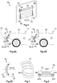
Figures 6A to 6C a sixth embodiment of the trim component 186 is shown.Figures 6A and 6B are a principle side view whereasFigure 6C is a principle top view of thevehicle 10. In contrast to the other embodiments the shutter element 30 consists of one single rigid and curved shutter segment 42. The shutter segment 42 is separately shown inFigure 7 by means of an exaggerated perspective view. The shutter segment 42 comprises in total six slot-like openings 44. Moreover the shutter segment 42 is curved wherein the curvature is approximated to the curvature of thefront grill 20 of the trim component 186 of the sixth embodiment. - When comparing
Figures 6A and 6B withFigure 6C one can see that the shutter segment 42 is curved in two planes. Both curvatures follow a circular path so that the shutter segment 42 is formed as a ball segment. Alternatively the shutter segment 42 may be formed as a cylinder segment or an ellipsoid segment. Thereby it is possible to move the shutter segment 42 along a circular path between the first position (Figure 6A ) and the second position (Figure 6B ). The design of the moving unit 36 (not shown) may be facilitated. As an example the movingunit 36 may comprise a gear wheel meshing with a toothed rack arranged on the shutter segment 42. A drive train may be provided between the motor and the gear wheel of the movingunit 36. The motor may be arranged at distance from the shutter segment 42. - Reference is now made to
Figures 6A and 6B . It is apparent that thefront grill 20 of the trim component 186 of the sixth embodiment comprises a number offins 46. The shape and the size of the slot-like openings 44 approximately correspond to those of thefins 46. In the first position (Figure 6A ) the slot-like openings 44 of the shutter segment 42 and thefins 46 of thefront grill 20 are arranged offset from each other so that air can penetrate through theopenings 44 and flow to the radiator 16. In the second position (Figure 6B ) the opening and thefins 46 are aligned with each other. The air cannot penetrate theopenings 44 anymore so that the air flow to the radiator 16 is interrupted. -
Figure 8 shows a principle front view of a trim component 187 according to a seventh embodiment. The trim component 187 comprises one mainfront grill 20M and two sub front grills 20S. All thefront grills fins 46. While the air flow through the mainfront grill 20M may be controlled by ashutter device 28 as shown inFigure 5 the air flow through the two sub front grills 20S may be controlled by ashutter device 28 as shown inFigures 6A to 6C . Other configurations are also conceivable. -
- 10
- vehicle
- 12
- engine compartment
- 14
- engine
- 16
- radiator
- 18
- trim component
- 181 - 187
- trim component
- 20
- front grill
- 20M
- main front grill
- 20S
- sub front grill
- 22
- bumper
- 23
- front end
- 24
- car body
- 26
- number plate
- 28
- shutter device
- 30
- shutter element
- 32
- planar shutter segment
- 34
- roller unit
- 36
- moving unit
- 38
- guidance element
- 40
- abutment element
- 42
- curved shutter segment
- 44
- opening
- 46
- fin
- AL
- lateral axis
- AV
- vertical axis
Claims (14)
- Trim component (18) of a vehicle (10), the vehicle (10) comprising an engine compartment (12) arranged on a front end (23) of the vehicle (10), the trim component (18) comprising- at least one front grill (20) partially delimiting the engine compartment (12) when mounted on the vehicle (10),- at least one bumper (22) arranged adjacent to the front grill (20) or in the vicinity of the front grill (20), the bumper (22) partially delimiting the engine compartment (12) when mounted on the vehicle (10), and- a shutter device (28) comprising a shutter element (30), the shutter element (30) being movable by means of a moving unit (36) between a first position in which the front grill (20) is open and a second position in which the front grill (20) is closed,- the shutter device (28) being fastened to the front grill (20) and/or the bumper (22).
- Trim component (18) according to claim 1,
characterized in that the shutter device (28) comprises at least one guidance element (38) cooperating with the shutter element (30), the guidance element (38) being- fastened to the front grill (20) and/or the bumper (22) or- an integral part of the front grill (20) and/or the bumper (22). - Trim component (18) according to claim 2,
characterized in that the guidance element (38) comprises at least one abutment element (40) defining the first position or the second position. - Trim component (18) according to one of the preceding claims,
characterized in that the shutter element (30) comprises a number of rigid and planar shutter segments (32) rotatably fastened to each other. - Trim component (18) according to claim 4,
characterized in that the shutter device (28) comprises at least one roller unit (34) on which the shutter segments (32) can be wound and unwound. - Trim component (18) according to claim 5,
characterized in that the moving unit (36) is fastened to the roller unit (34) or integrated thereto. - Trim component (18) according to one of the claims 5 or 6,
characterized in that the roller unit (34) is arranged parallel to the vertical axis (AV) or the lateral axis (AL) of the vehicle (10). - Trim component (18) according to one of the claims 5 to 7,
characterized in that the shutter device (28) comprises at least two roller units (34). - Trim component (18) according to claim 8,
characterized in that at least one roller unit (34) is arranged adjacent to one end of the front grill (20). - Trim component (18) according to one of the claims 8 or 9,
characterized in that at least one roller unit (34) is arranged in the center of the front grill (20) or adjacent to the center of the front grill (20). - Trim component (18) according to one of the claims 1 to 3, characterized in that- the front grill (20) comprises a number of fins (46), and- the shutter element (30) comprises at least one rigid shutter segment (42), each shutter segment (42) comprising a number of openings (44) the shape of which at least approximately corresponds to the shape of the fins (46),- wherein in the first position the fins (46) and openings (44) are arranged offset from each other and in the second position the fins (46) and openings (44) are aligned with each other.
- Trim component (18) according to claim 11,
characterized in that the shutter segment (42) is curved. - Trim component (18) according to claim 12,
characterized in that the shutter segment (42) is formed as a ball segment, an ellipsoid segment or a cylinder segment. - Vehicle (10), comprising- an engine compartment (12) arranged on a front end of the vehicle (10) and- a trim component (18) according to one of the preceding claims.
Priority Applications (2)
| Application Number | Priority Date | Filing Date | Title |
|---|---|---|---|
| ES19201763T ES2944714T3 (en) | 2019-10-07 | 2019-10-07 | Trim component of a vehicle and vehicle comprising such a trim component |
| EP19201763.0A EP3805031B1 (en) | 2019-10-07 | 2019-10-07 | Trim component of a vehicle and vehicle comprising such a trim component |
Applications Claiming Priority (1)
| Application Number | Priority Date | Filing Date | Title |
|---|---|---|---|
| EP19201763.0A EP3805031B1 (en) | 2019-10-07 | 2019-10-07 | Trim component of a vehicle and vehicle comprising such a trim component |
Publications (2)
| Publication Number | Publication Date |
|---|---|
| EP3805031A1 true EP3805031A1 (en) | 2021-04-14 |
| EP3805031B1 EP3805031B1 (en) | 2023-04-26 |
Family
ID=68172133
Family Applications (1)
| Application Number | Title | Priority Date | Filing Date |
|---|---|---|---|
| EP19201763.0A Active EP3805031B1 (en) | 2019-10-07 | 2019-10-07 | Trim component of a vehicle and vehicle comprising such a trim component |
Country Status (2)
| Country | Link |
|---|---|
| EP (1) | EP3805031B1 (en) |
| ES (1) | ES2944714T3 (en) |
Cited By (1)
| Publication number | Priority date | Publication date | Assignee | Title |
|---|---|---|---|---|
| CN113734086A (en) * | 2021-08-26 | 2021-12-03 | 浙江吉利控股集团有限公司 | Automobile moving grid system and automobile |
Citations (11)
| Publication number | Priority date | Publication date | Assignee | Title |
|---|---|---|---|---|
| FR2559432A1 (en) * | 1984-02-14 | 1985-08-16 | Daimler Benz Ag | Adjustable cover for vehicle radiator |
| EP0179304A1 (en) | 1984-10-23 | 1986-04-30 | Süddeutsche Kühlerfabrik Julius Fr. Behr GmbH & Co. KG | Radiator shutter |
| US20110203861A1 (en) * | 2010-02-19 | 2011-08-25 | Gm Global Technology Operations, Inc. | Impact and damage resistant front end airlfow control device |
| EP2855185A1 (en) | 2012-05-31 | 2015-04-08 | HBPO GmbH | Device for regulating an air flow to a cooler device of a vehicle and front end element of a vehicle |
| EP2903844A1 (en) | 2012-10-05 | 2015-08-12 | HBPO GmbH | Roller blind module for a cooling module of a vehicle and front end element for a vehicle |
| GB2524887A (en) * | 2015-03-03 | 2015-10-07 | Daimler Ag | Flow regulating device for a vehicle, in particular a motor vehicle |
| DE102014113067A1 (en) * | 2014-09-10 | 2016-03-10 | Dr. Ing. H.C. F. Porsche Aktiengesellschaft | Device for regulating cooling air in a motor vehicle |
| DE102015012965A1 (en) | 2015-10-08 | 2017-04-13 | Hbpo Gmbh | Device for regulating an air flow |
| DE202016103512U1 (en) * | 2016-07-01 | 2017-10-05 | Rehau Ag + Co | Roller shutter elements for regulating the flow of air through the grille in the engine compartment / Mobile closure assembly of the grille main opening of a land vehicle |
| KR101805715B1 (en) | 2011-08-24 | 2017-12-06 | 현대모비스 주식회사 | Airflap apparatus for an automobile |
| DE102017010105A1 (en) | 2017-10-27 | 2018-05-24 | Daimler Ag | Grille roller blind assembly for a motor vehicle and motor vehicle with such a grille roller blind assembly |
-
2019
- 2019-10-07 ES ES19201763T patent/ES2944714T3/en active Active
- 2019-10-07 EP EP19201763.0A patent/EP3805031B1/en active Active
Patent Citations (11)
| Publication number | Priority date | Publication date | Assignee | Title |
|---|---|---|---|---|
| FR2559432A1 (en) * | 1984-02-14 | 1985-08-16 | Daimler Benz Ag | Adjustable cover for vehicle radiator |
| EP0179304A1 (en) | 1984-10-23 | 1986-04-30 | Süddeutsche Kühlerfabrik Julius Fr. Behr GmbH & Co. KG | Radiator shutter |
| US20110203861A1 (en) * | 2010-02-19 | 2011-08-25 | Gm Global Technology Operations, Inc. | Impact and damage resistant front end airlfow control device |
| KR101805715B1 (en) | 2011-08-24 | 2017-12-06 | 현대모비스 주식회사 | Airflap apparatus for an automobile |
| EP2855185A1 (en) | 2012-05-31 | 2015-04-08 | HBPO GmbH | Device for regulating an air flow to a cooler device of a vehicle and front end element of a vehicle |
| EP2903844A1 (en) | 2012-10-05 | 2015-08-12 | HBPO GmbH | Roller blind module for a cooling module of a vehicle and front end element for a vehicle |
| DE102014113067A1 (en) * | 2014-09-10 | 2016-03-10 | Dr. Ing. H.C. F. Porsche Aktiengesellschaft | Device for regulating cooling air in a motor vehicle |
| GB2524887A (en) * | 2015-03-03 | 2015-10-07 | Daimler Ag | Flow regulating device for a vehicle, in particular a motor vehicle |
| DE102015012965A1 (en) | 2015-10-08 | 2017-04-13 | Hbpo Gmbh | Device for regulating an air flow |
| DE202016103512U1 (en) * | 2016-07-01 | 2017-10-05 | Rehau Ag + Co | Roller shutter elements for regulating the flow of air through the grille in the engine compartment / Mobile closure assembly of the grille main opening of a land vehicle |
| DE102017010105A1 (en) | 2017-10-27 | 2018-05-24 | Daimler Ag | Grille roller blind assembly for a motor vehicle and motor vehicle with such a grille roller blind assembly |
Cited By (2)
| Publication number | Priority date | Publication date | Assignee | Title |
|---|---|---|---|---|
| CN113734086A (en) * | 2021-08-26 | 2021-12-03 | 浙江吉利控股集团有限公司 | Automobile moving grid system and automobile |
| CN113734086B (en) * | 2021-08-26 | 2024-04-09 | 浙江吉利控股集团有限公司 | Automobile movable grille system and automobile |
Also Published As
| Publication number | Publication date |
|---|---|
| EP3805031B1 (en) | 2023-04-26 |
| ES2944714T3 (en) | 2023-06-23 |
Similar Documents
| Publication | Publication Date | Title |
|---|---|---|
| EP2574484B1 (en) | Grille shutter device | |
| US9365106B2 (en) | Device for regulating an air flow to a cooler device of a vehicle and front end element of a vehicle | |
| US8302714B2 (en) | Impact and damage resistant front end airflow control device | |
| US8708077B2 (en) | Grille shutter apparatus | |
| JP5937097B2 (en) | Cooling device having an air guide for a radiator of an automobile engine | |
| US20160016617A1 (en) | Front of a motor vehicle | |
| EP2357101B1 (en) | Sliding door device | |
| US9637180B2 (en) | Front-end structure of a motor vehicle | |
| US11807311B2 (en) | Air guide device of a motor vehicle body | |
| EP2942221B1 (en) | Vehicle grille apparatus | |
| US9216643B2 (en) | Stacking radiator aperture closure panels | |
| US20070209613A1 (en) | Cooling System | |
| CN114025980B (en) | Device for closing a motor vehicle cooling module | |
| US20140216835A1 (en) | Displaceable Covering for a Motor Vehicle | |
| US20160214464A1 (en) | Front end part of a motor vehicle | |
| EP3805031B1 (en) | Trim component of a vehicle and vehicle comprising such a trim component | |
| JP2012148705A (en) | Air intake opening and closing apparatus for vehicle | |
| CN102066142A (en) | Vehicle roof having sunroof guided on the outside | |
| KR20070058682A (en) | Indoor unit of air conditioner | |
| US10308094B2 (en) | Warm or cold air channel with slots to optimize control curves | |
| CN109774425B (en) | vehicle parts | |
| EP3178686B1 (en) | Motor vehicle body comprising shutters with splitters and associated vehicle | |
| US10538214B2 (en) | Controlled in-tank flow guide for heat exchanger | |
| CN108791537B (en) | Rear spoiler assembly for a motor vehicle | |
| US11554632B2 (en) | Air vent for introducing air into a motor vehicle interior |
Legal Events
| Date | Code | Title | Description |
|---|---|---|---|
| PUAI | Public reference made under article 153(3) epc to a published international application that has entered the european phase |
Free format text: ORIGINAL CODE: 0009012 |
|
| STAA | Information on the status of an ep patent application or granted ep patent |
Free format text: STATUS: THE APPLICATION HAS BEEN PUBLISHED |
|
| AK | Designated contracting states |
Kind code of ref document: A1 Designated state(s): AL AT BE BG CH CY CZ DE DK EE ES FI FR GB GR HR HU IE IS IT LI LT LU LV MC MK MT NL NO PL PT RO RS SE SI SK SM TR |
|
| AX | Request for extension of the european patent |
Extension state: BA ME |
|
| STAA | Information on the status of an ep patent application or granted ep patent |
Free format text: STATUS: REQUEST FOR EXAMINATION WAS MADE |
|
| 17P | Request for examination filed |
Effective date: 20210923 |
|
| RBV | Designated contracting states (corrected) |
Designated state(s): AL AT BE BG CH CY CZ DE DK EE ES FI FR GB GR HR HU IE IS IT LI LT LU LV MC MK MT NL NO PL PT RO RS SE SI SK SM TR |
|
| STAA | Information on the status of an ep patent application or granted ep patent |
Free format text: STATUS: EXAMINATION IS IN PROGRESS |
|
| 17Q | First examination report despatched |
Effective date: 20211206 |
|
| RAP3 | Party data changed (applicant data changed or rights of an application transferred) |
Owner name: MOTHERSON INNOVATIONS COMPANY LIMITED |
|
| GRAP | Despatch of communication of intention to grant a patent |
Free format text: ORIGINAL CODE: EPIDOSNIGR1 |
|
| STAA | Information on the status of an ep patent application or granted ep patent |
Free format text: STATUS: GRANT OF PATENT IS INTENDED |
|
| INTG | Intention to grant announced |
Effective date: 20221125 |
|
| GRAS | Grant fee paid |
Free format text: ORIGINAL CODE: EPIDOSNIGR3 |
|
| GRAA | (expected) grant |
Free format text: ORIGINAL CODE: 0009210 |
|
| STAA | Information on the status of an ep patent application or granted ep patent |
Free format text: STATUS: THE PATENT HAS BEEN GRANTED |
|
| AK | Designated contracting states |
Kind code of ref document: B1 Designated state(s): AL AT BE BG CH CY CZ DE DK EE ES FI FR GB GR HR HU IE IS IT LI LT LU LV MC MK MT NL NO PL PT RO RS SE SI SK SM TR |
|
| REG | Reference to a national code |
Ref country code: GB Ref legal event code: FG4D |
|
| REG | Reference to a national code |
Ref country code: CH Ref legal event code: EP |
|
| REG | Reference to a national code |
Ref country code: DE Ref legal event code: R096 Ref document number: 602019027978 Country of ref document: DE |
|
| REG | Reference to a national code |
Ref country code: AT Ref legal event code: REF Ref document number: 1562579 Country of ref document: AT Kind code of ref document: T Effective date: 20230515 |
|
| REG | Reference to a national code |
Ref country code: IE Ref legal event code: FG4D |
|
| P01 | Opt-out of the competence of the unified patent court (upc) registered |
Effective date: 20230427 |
|
| REG | Reference to a national code |
Ref country code: ES Ref legal event code: FG2A Ref document number: 2944714 Country of ref document: ES Kind code of ref document: T3 Effective date: 20230623 |
|
| REG | Reference to a national code |
Ref country code: LT Ref legal event code: MG9D |
|
| REG | Reference to a national code |
Ref country code: NL Ref legal event code: MP Effective date: 20230426 |
|
| REG | Reference to a national code |
Ref country code: AT Ref legal event code: MK05 Ref document number: 1562579 Country of ref document: AT Kind code of ref document: T Effective date: 20230426 |
|
| PG25 | Lapsed in a contracting state [announced via postgrant information from national office to epo] |
Ref country code: NL Free format text: LAPSE BECAUSE OF FAILURE TO SUBMIT A TRANSLATION OF THE DESCRIPTION OR TO PAY THE FEE WITHIN THE PRESCRIBED TIME-LIMIT Effective date: 20230426 |
|
| PG25 | Lapsed in a contracting state [announced via postgrant information from national office to epo] |
Ref country code: SE Free format text: LAPSE BECAUSE OF FAILURE TO SUBMIT A TRANSLATION OF THE DESCRIPTION OR TO PAY THE FEE WITHIN THE PRESCRIBED TIME-LIMIT Effective date: 20230426 Ref country code: PT Free format text: LAPSE BECAUSE OF FAILURE TO SUBMIT A TRANSLATION OF THE DESCRIPTION OR TO PAY THE FEE WITHIN THE PRESCRIBED TIME-LIMIT Effective date: 20230828 Ref country code: NO Free format text: LAPSE BECAUSE OF FAILURE TO SUBMIT A TRANSLATION OF THE DESCRIPTION OR TO PAY THE FEE WITHIN THE PRESCRIBED TIME-LIMIT Effective date: 20230726 Ref country code: AT Free format text: LAPSE BECAUSE OF FAILURE TO SUBMIT A TRANSLATION OF THE DESCRIPTION OR TO PAY THE FEE WITHIN THE PRESCRIBED TIME-LIMIT Effective date: 20230426 |
|
| PG25 | Lapsed in a contracting state [announced via postgrant information from national office to epo] |
Ref country code: RS Free format text: LAPSE BECAUSE OF FAILURE TO SUBMIT A TRANSLATION OF THE DESCRIPTION OR TO PAY THE FEE WITHIN THE PRESCRIBED TIME-LIMIT Effective date: 20230426 Ref country code: PL Free format text: LAPSE BECAUSE OF FAILURE TO SUBMIT A TRANSLATION OF THE DESCRIPTION OR TO PAY THE FEE WITHIN THE PRESCRIBED TIME-LIMIT Effective date: 20230426 Ref country code: LV Free format text: LAPSE BECAUSE OF FAILURE TO SUBMIT A TRANSLATION OF THE DESCRIPTION OR TO PAY THE FEE WITHIN THE PRESCRIBED TIME-LIMIT Effective date: 20230426 Ref country code: LT Free format text: LAPSE BECAUSE OF FAILURE TO SUBMIT A TRANSLATION OF THE DESCRIPTION OR TO PAY THE FEE WITHIN THE PRESCRIBED TIME-LIMIT Effective date: 20230426 Ref country code: IS Free format text: LAPSE BECAUSE OF FAILURE TO SUBMIT A TRANSLATION OF THE DESCRIPTION OR TO PAY THE FEE WITHIN THE PRESCRIBED TIME-LIMIT Effective date: 20230826 Ref country code: HR Free format text: LAPSE BECAUSE OF FAILURE TO SUBMIT A TRANSLATION OF THE DESCRIPTION OR TO PAY THE FEE WITHIN THE PRESCRIBED TIME-LIMIT Effective date: 20230426 Ref country code: GR Free format text: LAPSE BECAUSE OF FAILURE TO SUBMIT A TRANSLATION OF THE DESCRIPTION OR TO PAY THE FEE WITHIN THE PRESCRIBED TIME-LIMIT Effective date: 20230727 |
|
| PG25 | Lapsed in a contracting state [announced via postgrant information from national office to epo] |
Ref country code: FI Free format text: LAPSE BECAUSE OF FAILURE TO SUBMIT A TRANSLATION OF THE DESCRIPTION OR TO PAY THE FEE WITHIN THE PRESCRIBED TIME-LIMIT Effective date: 20230426 |
|
| PG25 | Lapsed in a contracting state [announced via postgrant information from national office to epo] |
Ref country code: SK Free format text: LAPSE BECAUSE OF FAILURE TO SUBMIT A TRANSLATION OF THE DESCRIPTION OR TO PAY THE FEE WITHIN THE PRESCRIBED TIME-LIMIT Effective date: 20230426 |
|
| REG | Reference to a national code |
Ref country code: DE Ref legal event code: R097 Ref document number: 602019027978 Country of ref document: DE |
|
| PG25 | Lapsed in a contracting state [announced via postgrant information from national office to epo] |
Ref country code: SM Free format text: LAPSE BECAUSE OF FAILURE TO SUBMIT A TRANSLATION OF THE DESCRIPTION OR TO PAY THE FEE WITHIN THE PRESCRIBED TIME-LIMIT Effective date: 20230426 Ref country code: SK Free format text: LAPSE BECAUSE OF FAILURE TO SUBMIT A TRANSLATION OF THE DESCRIPTION OR TO PAY THE FEE WITHIN THE PRESCRIBED TIME-LIMIT Effective date: 20230426 Ref country code: RO Free format text: LAPSE BECAUSE OF FAILURE TO SUBMIT A TRANSLATION OF THE DESCRIPTION OR TO PAY THE FEE WITHIN THE PRESCRIBED TIME-LIMIT Effective date: 20230426 Ref country code: EE Free format text: LAPSE BECAUSE OF FAILURE TO SUBMIT A TRANSLATION OF THE DESCRIPTION OR TO PAY THE FEE WITHIN THE PRESCRIBED TIME-LIMIT Effective date: 20230426 Ref country code: DK Free format text: LAPSE BECAUSE OF FAILURE TO SUBMIT A TRANSLATION OF THE DESCRIPTION OR TO PAY THE FEE WITHIN THE PRESCRIBED TIME-LIMIT Effective date: 20230426 Ref country code: CZ Free format text: LAPSE BECAUSE OF FAILURE TO SUBMIT A TRANSLATION OF THE DESCRIPTION OR TO PAY THE FEE WITHIN THE PRESCRIBED TIME-LIMIT Effective date: 20230426 |
|
| PLBE | No opposition filed within time limit |
Free format text: ORIGINAL CODE: 0009261 |
|
| STAA | Information on the status of an ep patent application or granted ep patent |
Free format text: STATUS: NO OPPOSITION FILED WITHIN TIME LIMIT |
|
| 26N | No opposition filed |
Effective date: 20240129 |
|
| PG25 | Lapsed in a contracting state [announced via postgrant information from national office to epo] |
Ref country code: SI Free format text: LAPSE BECAUSE OF FAILURE TO SUBMIT A TRANSLATION OF THE DESCRIPTION OR TO PAY THE FEE WITHIN THE PRESCRIBED TIME-LIMIT Effective date: 20230426 |
|
| PG25 | Lapsed in a contracting state [announced via postgrant information from national office to epo] |
Ref country code: SI Free format text: LAPSE BECAUSE OF FAILURE TO SUBMIT A TRANSLATION OF THE DESCRIPTION OR TO PAY THE FEE WITHIN THE PRESCRIBED TIME-LIMIT Effective date: 20230426 Ref country code: IT Free format text: LAPSE BECAUSE OF FAILURE TO SUBMIT A TRANSLATION OF THE DESCRIPTION OR TO PAY THE FEE WITHIN THE PRESCRIBED TIME-LIMIT Effective date: 20230426 Ref country code: MC Free format text: LAPSE BECAUSE OF FAILURE TO SUBMIT A TRANSLATION OF THE DESCRIPTION OR TO PAY THE FEE WITHIN THE PRESCRIBED TIME-LIMIT Effective date: 20230426 |
|
| REG | Reference to a national code |
Ref country code: CH Ref legal event code: PL |
|
| REG | Reference to a national code |
Ref country code: BE Ref legal event code: MM Effective date: 20231031 |
|
| PG25 | Lapsed in a contracting state [announced via postgrant information from national office to epo] |
Ref country code: LU Free format text: LAPSE BECAUSE OF NON-PAYMENT OF DUE FEES Effective date: 20231007 |
|
| GBPC | Gb: european patent ceased through non-payment of renewal fee |
Effective date: 20231007 |
|
| PG25 | Lapsed in a contracting state [announced via postgrant information from national office to epo] |
Ref country code: LU Free format text: LAPSE BECAUSE OF NON-PAYMENT OF DUE FEES Effective date: 20231007 |
|
| PG25 | Lapsed in a contracting state [announced via postgrant information from national office to epo] |
Ref country code: GB Free format text: LAPSE BECAUSE OF NON-PAYMENT OF DUE FEES Effective date: 20231007 |
|
| PG25 | Lapsed in a contracting state [announced via postgrant information from national office to epo] |
Ref country code: CH Free format text: LAPSE BECAUSE OF NON-PAYMENT OF DUE FEES Effective date: 20231031 |
|
| PG25 | Lapsed in a contracting state [announced via postgrant information from national office to epo] |
Ref country code: GB Free format text: LAPSE BECAUSE OF NON-PAYMENT OF DUE FEES Effective date: 20231007 Ref country code: CH Free format text: LAPSE BECAUSE OF NON-PAYMENT OF DUE FEES Effective date: 20231031 |
|
| PG25 | Lapsed in a contracting state [announced via postgrant information from national office to epo] |
Ref country code: BE Free format text: LAPSE BECAUSE OF NON-PAYMENT OF DUE FEES Effective date: 20231031 |
|
| PG25 | Lapsed in a contracting state [announced via postgrant information from national office to epo] |
Ref country code: IE Free format text: LAPSE BECAUSE OF NON-PAYMENT OF DUE FEES Effective date: 20231007 |
|
| PG25 | Lapsed in a contracting state [announced via postgrant information from national office to epo] |
Ref country code: IE Free format text: LAPSE BECAUSE OF NON-PAYMENT OF DUE FEES Effective date: 20231007 |
|
| PG25 | Lapsed in a contracting state [announced via postgrant information from national office to epo] |
Ref country code: BG Free format text: LAPSE BECAUSE OF FAILURE TO SUBMIT A TRANSLATION OF THE DESCRIPTION OR TO PAY THE FEE WITHIN THE PRESCRIBED TIME-LIMIT Effective date: 20230426 |
|
| PG25 | Lapsed in a contracting state [announced via postgrant information from national office to epo] |
Ref country code: BG Free format text: LAPSE BECAUSE OF FAILURE TO SUBMIT A TRANSLATION OF THE DESCRIPTION OR TO PAY THE FEE WITHIN THE PRESCRIBED TIME-LIMIT Effective date: 20230426 |
|
| PG25 | Lapsed in a contracting state [announced via postgrant information from national office to epo] |
Ref country code: CY Free format text: LAPSE BECAUSE OF FAILURE TO SUBMIT A TRANSLATION OF THE DESCRIPTION OR TO PAY THE FEE WITHIN THE PRESCRIBED TIME-LIMIT; INVALID AB INITIO Effective date: 20191007 |
|
| PG25 | Lapsed in a contracting state [announced via postgrant information from national office to epo] |
Ref country code: HU Free format text: LAPSE BECAUSE OF FAILURE TO SUBMIT A TRANSLATION OF THE DESCRIPTION OR TO PAY THE FEE WITHIN THE PRESCRIBED TIME-LIMIT; INVALID AB INITIO Effective date: 20191007 |
|
| PG25 | Lapsed in a contracting state [announced via postgrant information from national office to epo] |
Ref country code: TR Free format text: LAPSE BECAUSE OF FAILURE TO SUBMIT A TRANSLATION OF THE DESCRIPTION OR TO PAY THE FEE WITHIN THE PRESCRIBED TIME-LIMIT Effective date: 20230426 |
|
| PGFP | Annual fee paid to national office [announced via postgrant information from national office to epo] |
Ref country code: DE Payment date: 20251020 Year of fee payment: 7 |
|
| PGFP | Annual fee paid to national office [announced via postgrant information from national office to epo] |
Ref country code: FR Payment date: 20251022 Year of fee payment: 7 |
|
| PGFP | Annual fee paid to national office [announced via postgrant information from national office to epo] |
Ref country code: ES Payment date: 20251114 Year of fee payment: 7 |