EP3803323B1 - Station and method for mesuring airborne molecular contamination - Google Patents
Station and method for mesuring airborne molecular contamination Download PDFInfo
- Publication number
- EP3803323B1 EP3803323B1 EP19730689.7A EP19730689A EP3803323B1 EP 3803323 B1 EP3803323 B1 EP 3803323B1 EP 19730689 A EP19730689 A EP 19730689A EP 3803323 B1 EP3803323 B1 EP 3803323B1
- Authority
- EP
- European Patent Office
- Prior art keywords
- sampling
- measurement
- sampling line
- conditioning
- lines
- Prior art date
- Legal status (The legal status is an assumption and is not a legal conclusion. Google has not performed a legal analysis and makes no representation as to the accuracy of the status listed.)
- Active
Links
- 238000011109 contamination Methods 0.000 title claims description 20
- 238000000034 method Methods 0.000 title claims description 6
- 238000005070 sampling Methods 0.000 claims description 131
- 238000005259 measurement Methods 0.000 claims description 68
- 230000003750 conditioning effect Effects 0.000 claims description 41
- 238000012163 sequencing technique Methods 0.000 claims description 27
- 230000001143 conditioned effect Effects 0.000 claims description 8
- 238000000691 measurement method Methods 0.000 claims 2
- 239000007789 gas Substances 0.000 description 33
- 238000004891 communication Methods 0.000 description 12
- 238000005086 pumping Methods 0.000 description 12
- 238000012360 testing method Methods 0.000 description 11
- 235000021183 entrée Nutrition 0.000 description 6
- 238000004519 manufacturing process Methods 0.000 description 6
- 239000004065 semiconductor Substances 0.000 description 6
- 238000007872 degassing Methods 0.000 description 5
- 239000000758 substrate Substances 0.000 description 5
- ARXJGSRGQADJSQ-UHFFFAOYSA-N 1-methoxypropan-2-ol Chemical compound COCC(C)O ARXJGSRGQADJSQ-UHFFFAOYSA-N 0.000 description 4
- 239000002253 acid Substances 0.000 description 3
- QGZKDVFQNNGYKY-UHFFFAOYSA-N Ammonia Chemical compound N QGZKDVFQNNGYKY-UHFFFAOYSA-N 0.000 description 2
- KRHYYFGTRYWZRS-UHFFFAOYSA-N Fluorane Chemical compound F KRHYYFGTRYWZRS-UHFFFAOYSA-N 0.000 description 2
- 150000007513 acids Chemical class 0.000 description 2
- 238000012544 monitoring process Methods 0.000 description 2
- 229920001343 polytetrafluoroethylene Polymers 0.000 description 2
- 239000004810 polytetrafluoroethylene Substances 0.000 description 2
- 235000012431 wafers Nutrition 0.000 description 2
- 229920001774 Perfluoroether Polymers 0.000 description 1
- 229910021529 ammonia Inorganic materials 0.000 description 1
- IXCSERBJSXMMFS-UHFFFAOYSA-N hcl hcl Chemical compound Cl.Cl IXCSERBJSXMMFS-UHFFFAOYSA-N 0.000 description 1
- 239000000463 material Substances 0.000 description 1
- 238000004806 packaging method and process Methods 0.000 description 1
- 239000002245 particle Substances 0.000 description 1
- -1 polytetrafluoroethylene Polymers 0.000 description 1
- 239000002904 solvent Substances 0.000 description 1
- 238000001179 sorption measurement Methods 0.000 description 1
Images

Classifications
-
- G—PHYSICS
- G01—MEASURING; TESTING
- G01N—INVESTIGATING OR ANALYSING MATERIALS BY DETERMINING THEIR CHEMICAL OR PHYSICAL PROPERTIES
- G01N1/00—Sampling; Preparing specimens for investigation
- G01N1/02—Devices for withdrawing samples
- G01N1/22—Devices for withdrawing samples in the gaseous state
- G01N1/26—Devices for withdrawing samples in the gaseous state with provision for intake from several spaces
-
- G—PHYSICS
- G01—MEASURING; TESTING
- G01N—INVESTIGATING OR ANALYSING MATERIALS BY DETERMINING THEIR CHEMICAL OR PHYSICAL PROPERTIES
- G01N33/00—Investigating or analysing materials by specific methods not covered by groups G01N1/00 - G01N31/00
- G01N33/0004—Gaseous mixtures, e.g. polluted air
- G01N33/0009—General constructional details of gas analysers, e.g. portable test equipment
- G01N33/0011—Sample conditioning
Definitions
- the present invention relates to a station for measuring the molecular contamination carried by the air, intended in particular for monitoring the concentrations of molecular contamination in the atmosphere of clean rooms, such as the clean rooms of factories manufacturing semiconductors.
- the present invention also relates to a method for measuring the molecular contamination conveyed by the air by means of such a station.
- substrates such as semiconductor wafers or photomasks
- airborne molecular contamination or AMC for "Airbone Molecular Contamination” in English
- the substrates are contained in transport and atmospheric storage boxes, making it possible to transport the substrates from one equipment to another or to store them between two manufacturing steps.
- the transport boxes and the equipment are arranged inside clean rooms in which the level of particles is minimized and the temperature, humidity and pressure are maintained at precise levels.
- the gaseous species conveyed by the air can have different sources and different natures, one finds for example acids, bases, condensable elements, doping elements. These molecules can come from the air inside the semiconductor manufacturing plant or can be released in particular by the semiconductor wafers that have undergone prior manufacturing operations.
- Gas analyzers present in the clean rooms make it possible to evaluate the concentration of gaseous species conveyed by the air in real time, in particular that of humidity and some acids. The concentrations measured are sometimes very low, such as of the order of ppm or ppb. These gas analyzers measure the surrounding gaseous atmosphere, it is therefore necessary to provide a gas analyzer in each area to be tested in the clean room.
- One solution is to vacuum simultaneously in all the sampling lines. All the sampling lines are thus conditioned by means of a common evacuation, a measurement of the concentration of the gas being carried out in a single line at a time. The gas is thus constantly sucked into all the sampling lines, which in particular allows good degassing of the sampling lines.
- Such known systems are disclosed for example in the documents KR20110026918A and US3043145A .
- One of the aims of the present invention is to propose a measuring station which at least partially solves the aforementioned drawbacks.
- the subject of the invention is a station for measuring the molecular contamination conveyed by the air comprising at least one gas analyzer and a conditioning pump characterized in that it further comprises a sequencing unit comprising a sequencing program defining an order of the measurements to be carried out for at least two sampling lines, the sequencing unit being configured to control the communication of a sampling line to be measured, for example a single and unique line of sampling, the measurement of which is programmed consecutively to a sampling line being measured, with the conditioning pump, while controlling the communication of the sampling line being measured with the at least one gas analyzer.
- a sequencing unit comprising a sequencing program defining an order of the measurements to be carried out for at least two sampling lines, the sequencing unit being configured to control the communication of a sampling line to be measured, for example a single and unique line of sampling, the measurement of which is programmed consecutively to a sampling line being measured, with the conditioning pump, while controlling the communication of the sampling line being measured with the at least one gas analyzer.
- the sampling line can thus be conditioned in optimal and rapid pumping conditions.
- the measurement time is reduced because the conditioning of the sampling line is carried out in masked time.
- a maximum of pumping can be used for conditioning, regardless of the number of sampling lines.
- the number of sampling lines can therefore be increased without this modifying the pumping performance for conditioning.
- the gas thus sucked in before the line is measured allows degassing of the sampling line.
- the measurements can then be more precise, in particular in cases where a significant change in concentration takes place between two areas to be tested consecutively and where sufficient degassing time is necessary to obtain a measurement that is truly representative of the concentration in the test area. .
- the invention provides a measuring station according to claim 1 and a measuring method according to claim 6.
- the Figure 1 shows elements of a station 1 for measuring airborne molecular contamination, intended in particular for monitoring the concentrations of molecular contamination in the atmosphere of clean rooms, such as the clean rooms of manufacturing plants for semiconductors.
- the measuring station 1 includes at least one gas analyzer 2, one conditioning pump 3 and one sequencing unit 4.
- the gas analyzer 2 comprises a small sampling pump.
- the gas analyzer 2 makes it possible to measure the concentration of at least one gaseous species in real time, that is to say with a measurement duration of less than a few seconds, or even a few minutes, for low concentrations below the ppm or ppb.
- the gaseous species measured is for example an acid, such as hydrofluoric acid HF or hydrochloric acid HCl or a solvent, such as PGMEA (propylene glycol methyl ether).
- the gaseous species is ammonia NH 3 .
- a gas analyzer 2 can be adapted for measuring a distinct gaseous species or a group of distinct gaseous species.
- the conditioning pump 3 comprises for example a small capacity vacuum pump, such as a small multistage vacuum pump.
- the sequencing unit 4 is for example a computer.
- the sequencing unit 4 comprises a sequencing program defining an order of the measurements to be carried out for at least two sampling lines among the sampling lines L1-L16.
- the L1-L16 sampling lines include, for example, flexible pipes, made of materials that limit the adhesion of gaseous species to the walls, such as perfluoroalkoxy (also called PFA) or polytetrafluoroethylene (also called PTFE).
- the L1-L16 sampling lines connect the measuring station 1 to particular test areas of the clean room.
- the length of the sampling lines L1-L16 may vary between the different test zones to be joined and may have several tens of meters, such as a length of between 40 and 200 meters.
- the sequencing program defines the order of the measurements to be carried out, i.e. in which order the concentration measurements of gaseous species must be carried out in the sampling lines L1-L16 connected to measurement station 1.
- the sequencing unit 4 is further configured to control the communication of a sampling line L1-L16, for example a single and unique sampling line, to be measured with the conditioning pump 3 while it is controls the communication of the sampling line L1-L16 being measured with the at least one gas analyzer 2.
- a sampling line L1-L16 for example a single and unique sampling line
- sampling line “being measured” is the one whose measurement is programmed consecutively to the sampling line L1-L16 being measured.
- gas analyzers 2 for measuring concentrations of different gases or groups of gaseous species, can be connected to inlet 9 to sample simultaneously in the same sampling line.
- the first conditioning solenoid valve 6a and the first measurement solenoid valve 8a are connected to sampling solenoid valves 5 of a first series S1 of sampling lines L1, L3, L5, L7, L9, L11, L13, L15.
- the first series S1 of sampling lines comprises at least one sampling line.
- the second conditioning solenoid valve 6b and the second measurement solenoid valve 8b are connected to sampling solenoid valves 5 of a second series S2 of sampling lines L2, L4, L6, L8, L10, L12, L14, L16.
- the second series S2 of sampling lines comprises at least one sampling line.
- sampling lines L1-L16 each provided with a sampling solenoid valve 5, such as sixteen sampling lines L1-16.
- the first series S1 of sampling lines comprises for example the same number of sampling lines as the second series S2 (eight in the example).
- the sequencing program defines for example an order of the measurements to be performed which alternates the measurements to be performed in each series S1, S2 of sampling lines. This solution makes it possible to limit the number of valves used, which makes it possible to simplify the device and control costs.
- a sampling line L1-L16 is conditioned, for example a single and unique sampling line, the measurement of which is programmed consecutively to a sampling line L1-L16 being measured while measuring in the line sampling line L1-L16 with the at least one gas analyzer 2.
- the measurements to be carried out in each of the two series S1, S2 of sampling lines are alternated.
- a sequencing program defining that a measurement of the concentration of the gaseous species must be carried out in the sampling line L5 of the first series S1 followed by a measurement in the sampling line L4 of the second series S2, we conditions the sampling line L4 of the second series S2 while measuring in the sampling line L5 with the at least one gas analyzer 2.
- the sequencing unit 4 controls the communication of the sampling line L4 with the conditioning pump 3 by opening the sampling solenoid valve 5 of the sampling line L4 as well as the second conditioning solenoid valve 6b, the first conditioning solenoid valve 6a connected to the sampling solenoid valves 5 of the first series S1 being closed.
- the sequencing unit 4 controls the communication of the sampling line L5 with the at least one gas analyzer 2 by opening the sampling solenoid valve 5 of the sampling line L5 as well as the first measurement solenoid valve 8a , the second measurement solenoid valve 8b connected to the sampling solenoid valves 5 of the second series S2 being closed (step 101, Figure 2 ).
- the sequencing unit 4 controls the placing of the sampling line L4 in communication with the at least one gas analyzer 2 by opening the sampling solenoid valve 5 of the sampling line L4 as well as the second measuring solenoid valve 8b, the first measuring solenoid valve 8a connected to the sampling solenoid valves 5 of the first series S1 being closed.
- the sequencing unit 4 controls the setting in communication of the sampling line of the first series S1 of which a concentration measurement of the gaseous species must be carried out consecutively, with the conditioning pump 3 (step 102, Figure 2 ).
- Operations can continue in this way until all measurements defined in the sequencing program are performed in order. These operations can be repeated in a loop.
- sampling lines can therefore be conditioned in optimal and fast pumping conditions.
- the measurement time is reduced because the conditioning of the sampling line is carried out in masked time.
- a maximum of pumping can be used for conditioning, regardless of the number of sampling lines.
- the number of sampling lines can therefore be increased without this modifying the pumping performance for conditioning.
- the gas thus sucked in before the line is measured allows degassing of the sampling line. Measurements can then be more accurate, especially in cases where a large concentration change has place between two areas to be tested consecutively and where sufficient degassing time is necessary to obtain a measurement that is truly representative of the concentration in the test area.
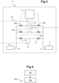
- the Figure 3 illustrates a second embodiment of the measuring station 1'.
- the first measurement solenoid valve 12 and the first conditioning solenoid valve 11 are connected to a sampling line L1.
- the at least second measurement solenoid valve 14a, 14b and the at least second conditioning solenoid valve 13a, 13b are connected to at least one sampling line L2, L3.
- sampling lines L1-L3 there are three sampling lines L1-L3, that is to say two second conditioning solenoid valves 13a, 13b arranged as a branch from the first conditioning solenoid valve 11 and from the inlet 7 of the packaging 3, and two second measurement solenoid valves 14a, 14b arranged as a branch from the first measurement solenoid valve 12 and from the inlet 9 of at least one gas analyzer 2.
- the two second measurement solenoid valves 14a, 14b and the two second conditioning solenoid valves 13a, 13b are connected to two respective sampling lines L2, L3.
- the measuring station 1' according to this second embodiment to comprise less than four second conditioning solenoid valves and less than four second measuring solenoid valves, the measuring station 1 being connected to at most five sampling lines L1-L5. Indeed, beyond five, the number of solenoid valves required increases the cost of the measuring station 1′ relatively significantly.
- a sampling line is conditioned, for example a single and unique sampling line, the measurement of which is programmed consecutively to a sampling line being measured while measuring in the sampling line with the at least a gas analyzer 2.
- the sampling line L3 is conditioned while the measurement is taken in the sampling line L2 with the at least one gas analyzer 2.
- the sequencing unit 4 controls the communication of the sampling line L3 with the conditioning pump 3 by opening the second sampling solenoid valve 13b of the sampling line L3, the second measurement solenoid valve 14b of the line sampling L3 being closed.
- the sequencing unit 4 controls the communication of the sampling line L2 with the at least one gas analyzer 2 by opening the second measurement solenoid valve 14a of the sampling line L2, the second sampling solenoid valve 13a being closed (step 101, Figure 4 ).
- the sequencing unit 4 controls the placing of the sampling line L3 in communication with the at least one gas analyzer 2 by opening the second measuring solenoid valve 14b of the sampling line L3 and by closing the second sampling solenoid valve 13b of the sampling line L3 and the second measuring solenoid valve 14a of the sampling line L2.
- the sequencing unit 4 controls the communication of the sampling line, a gaseous species concentration measurement of which must be carried out consecutively, with the conditioning pump 3 (step 102, Figure 4 ).
- Operations can continue in this way until all measurements defined in the sequencing program are performed in order. These operations can be repeated in a loop.
Description
La présente invention se rapporte à une station de mesure de la contamination moléculaire véhiculée par l'air, destinée en particulier à la surveillance des concentrations en contamination moléculaire dans l'atmosphère des salles blanches, telles que les salles blanches d'usines de fabrication de semi-conducteurs. La présente invention se rapporte également à un procédé de mesure de la contamination moléculaire véhiculée par l'air au moyen d'une telle station.The present invention relates to a station for measuring the molecular contamination carried by the air, intended in particular for monitoring the concentrations of molecular contamination in the atmosphere of clean rooms, such as the clean rooms of factories manufacturing semiconductors. The present invention also relates to a method for measuring the molecular contamination conveyed by the air by means of such a station.
Dans l'industrie de fabrication de semi-conducteurs, les substrats, tels que les plaquettes de semi-conducteurs (ou « wafer » en anglais) ou les photomasques, doivent être protégés de la contamination moléculaire véhiculée par l'air (ou AMC pour « Airbone Molecular Contamination » en anglais) afin d'éviter que celle-ci n'endommage les puces ou circuits électroniques des substrats. Pour cela, les substrats sont contenus dans des boîtes de transport et de stockage atmosphérique, permettant de transporter les substrats d'un équipement à l'autre ou de les stocker entre deux étapes de fabrication. Par ailleurs, les boites de transport et les équipements sont agencés à l'intérieur de salles blanches dans lesquelles le niveau de particules est minimisé et la température, l'humidité et la pression sont maintenus à des niveaux précis.In the semiconductor manufacturing industry, substrates, such as semiconductor wafers or photomasks, must be protected from airborne molecular contamination (or AMC for "Airbone Molecular Contamination" in English) in order to prevent it from damaging the chips or electronic circuits of the substrates. For this, the substrates are contained in transport and atmospheric storage boxes, making it possible to transport the substrates from one equipment to another or to store them between two manufacturing steps. In addition, the transport boxes and the equipment are arranged inside clean rooms in which the level of particles is minimized and the temperature, humidity and pressure are maintained at precise levels.
Dans la salle blanche, les espèces gazeuses véhiculées par l'air peuvent avoir différentes sources et différentes natures, on trouve par exemple des acides, des bases, des éléments condensables, des éléments dopants. Ces molécules peuvent provenir de l'air intérieur de l'usine de fabrication de semi-conducteurs ou peuvent être relâchés notamment par les plaquettes semi-conductrices ayant subi des opérations préalables de fabrication.In the clean room, the gaseous species conveyed by the air can have different sources and different natures, one finds for example acids, bases, condensable elements, doping elements. These molecules can come from the air inside the semiconductor manufacturing plant or can be released in particular by the semiconductor wafers that have undergone prior manufacturing operations.
Des analyseurs de gaz présents dans les salles blanches permettent d'évaluer la concentration des espèces gazeuses véhiculées par l'air en temps réel, notamment celle de l'humidité et de quelques acides. Les concentrations mesurées sont parfois très faibles, telles que de l'ordre du ppm ou du ppb. Ces analyseurs de gaz mesurant l'atmosphère gazeuse les environnants, il est donc nécessaire de prévoir un analyseur de gaz dans chaque zone à tester de la salle blanche.Gas analyzers present in the clean rooms make it possible to evaluate the concentration of gaseous species conveyed by the air in real time, in particular that of humidity and some acids. The concentrations measured are sometimes very low, such as of the order of ppm or ppb. These gas analyzers measure the surrounding gaseous atmosphere, it is therefore necessary to provide a gas analyzer in each area to be tested in the clean room.
Il existe un besoin d'augmenter le nombre d'espèces gazeuses mesurées et le nombre de zones de test afin de réduire les risques de contamination des substrats. Cependant, la multiplication des analyseurs par zone et la multiplication de ces zones à tester rend cette solution rapidement très couteuse.There is a need to increase the number of gaseous species measured and the number of test zones in order to reduce the risks of contamination of the substrates. However, the multiplication of analyzers per zone and the multiplication of these zones to be tested quickly makes this solution very expensive.
Pour réduire les coûts, on a proposé une unité de mesure regroupant différents analyseurs. L'unité est munie de plusieurs ports d'entrée adressant chacun une zone de test particulière de la salle blanche. Les salles blanches pouvant atteindre des dimensions importantes et le nombre de zones de test étant lui aussi en augmentation, il s'avère nécessaire d'utiliser un nombre conséquent de lignes de prélèvement, les longueurs de ces lignes atteignant le plus souvent plusieurs dizaines de mètres. Ce long parcours du gaz pour atteindre la cellule de mesure de l'analyseur prend du temps, ce qui implique un retard dans l'information. Il faut en effet « remplacer » tout le volume contenu dans la ligne de prélèvement par le gaz à mesurer au moins une fois, ce gaz pouvant en outre facilement se coller aux parois de la ligne par adsorption, en particulier pour les espèces gazeuses à mesurer dites polaires. Il peut alors être difficile d'obtenir une mesure réellement représentative de la concentration des espèces gazeuses dans la zone de test à moins d'attendre un temps très long à chaque changement de zone de test.To reduce the costs, a unit of measurement grouping together different analyzers has been proposed. The unit is equipped with several input ports each addressing a particular test area of the clean room. Since clean rooms can reach large dimensions and the number of test areas is also increasing, it is necessary to use a large number of sampling lines, the lengths of these lines most often reaching several tens of meters . This long journey of the gas to reach the analyzer's measurement cell takes time, which implies a delay in the information. It is in fact necessary to "replace" the entire volume contained in the sampling line with the gas to be measured at least once, this gas also being able to easily stick to the walls of the line by adsorption, in particular for the gaseous species to be measured. say polar. It may then be difficult to obtain a measurement that is truly representative of the concentration of the gaseous species in the test zone unless you wait a very long time each time the test zone is changed.
Une solution consiste à aspirer simultanément dans toutes les lignes de prélèvement. Toutes les lignes de prélèvement sont ainsi conditionnées au moyen d'une évacuation commune, une mesure de la concentration du gaz étant réalisée dans une seule ligne à la fois. Le gaz est ainsi constamment aspiré dans toutes les lignes de prélèvement, ce qui permet notamment un bon dégazage des lignes de prélèvement. De tels systèmes connus sont divulgués par exemple dans les documents
Le nombre de lignes à prélever simultanément étant important, cette solution engendre toutefois une forte réduction du débit de pompage dans chacune des lignes. Le temps de réponse dans la ligne de prélèvement pour laquelle une mesure est réalisée est alors allongé par rapport à une solution où la totalité du débit de pompage est consacré au prélèvement de la seule ligne à mesurer. Par ailleurs, les lignes de prélèvement n'ont pas toutes la même longueur. Certaines lignes peuvent être très courtes et d'autres très longues. Les débits de pompage peuvent donc présenter de fortes disparités entre les lignes. Des cas peuvent même se présenter où la différence de longueur entre deux lignes est tellement grande qu'un débit de pompage correct dans une ligne équivaut à un débit de pompage quasiment nul dans une autre.Since the number of lines to be sampled simultaneously is large, this solution nevertheless generates a significant reduction in the pumping rate in each of the lines. The response time in the sampling line for which a measurement is made is then lengthened compared to a solution where the entire pumping flow rate is devoted to sampling the single line to be measured. Furthermore, the sampling lines do not all have the same length. Some lines can be very short and others very long. The pumping rates can therefore show strong disparities between the lines. Cases may even arise where the difference in length between two lines is so great that a correct pumping rate in one line is equivalent to almost zero pumping rate in another.
Une solution pourrait être d'augmenter la capacité de pompage du prélèvement simultané. Cela engendre cependant un coût relativement important.One solution could be to increase the pumping capacity of the simultaneous withdrawal. However, this generates a relatively high cost.
Un des buts de la présente invention est de proposer une station de mesure qui résolve au moins partiellement les inconvénients précités.One of the aims of the present invention is to propose a measuring station which at least partially solves the aforementioned drawbacks.
A cet effet, l'invention a pour objet une station de mesure de la contamination moléculaire véhiculée par l'air comportant au moins un analyseur de gaz et une pompe de conditionnement caractérisée en ce qu'elle comporte en outre une unité de séquençage comportant un programme de séquençage définissant un ordre des mesures à réaliser pour au moins deux lignes de prélèvement, l'unité de séquençage étant configurée pour piloter la mise en communication d'une ligne de prélèvement à mesurer, par exemple d'une seule et unique ligne de prélèvement, dont la mesure est programmée consécutivement à une ligne de prélèvement en cours de mesure, avec la pompe de conditionnement, pendant le pilotage de la mise en communication de la ligne de prélèvement en cours de mesure avec le au moins un analyseur de gaz.To this end, the subject of the invention is a station for measuring the molecular contamination conveyed by the air comprising at least one gas analyzer and a conditioning pump characterized in that it further comprises a sequencing unit comprising a sequencing program defining an order of the measurements to be carried out for at least two sampling lines, the sequencing unit being configured to control the communication of a sampling line to be measured, for example a single and unique line of sampling, the measurement of which is programmed consecutively to a sampling line being measured, with the conditioning pump, while controlling the communication of the sampling line being measured with the at least one gas analyzer.
La ligne de prélèvement peut ainsi être conditionnée dans des conditions de pompage optimales et rapides.The sampling line can thus be conditioned in optimal and rapid pumping conditions.
En effet, le temps de mesure est réduit car le conditionnement de la ligne de prélèvement est réalisé en temps masqué.Indeed, the measurement time is reduced because the conditioning of the sampling line is carried out in masked time.
En outre, un maximum de pompage peut être utilisé pour le conditionnement et ce, quelque soit le nombre de lignes de prélèvement. Le nombre de lignes de prélèvement peut donc être augmenté sans que cela modifie les performances de pompage pour le conditionnement. Le gaz ainsi aspiré avant que la ligne soit mesurée permet un dégazage de la ligne de prélèvement. Les mesures peuvent alors être plus précises, en particulier dans les cas où un changement de concentration important a lieu entre deux zones à tester consécutivement et où un temps de dégazage suffisant est nécessaire pour obtenir une mesure réellement représentative de la concentration dans la zone de test.In addition, a maximum of pumping can be used for conditioning, regardless of the number of sampling lines. The number of sampling lines can therefore be increased without this modifying the pumping performance for conditioning. The gas thus sucked in before the line is measured allows degassing of the sampling line. The measurements can then be more precise, in particular in cases where a significant change in concentration takes place between two areas to be tested consecutively and where sufficient degassing time is necessary to obtain a measurement that is truly representative of the concentration in the test area. .
Il est ainsi possible de mesurer la concentration de différentes espèces gazeuses véhiculées par l'air à différents endroits de la salle blanche avec un même ensemble d'analyseurs de gaz, la station de mesure adressant un port d'entrée dans chaque zone de test de la salle blanche. On limite ainsi les coûts. L'invention prévoit une station de mesure selon la revendication 1 et un procédé de mesure selon la revendication 6.It is thus possible to measure the concentration of different gaseous species conveyed by the air at different places in the clean room with the same set of gas analyzers, the measuring station addressing an entry port in each test zone of the white room. This limits the costs. The invention provides a measuring station according to
D'autres caractéristiques et avantages de l'invention ressortiront de la description suivante, donnée à titre d'exemple, sans caractère limitatif, en regard des dessins annexés sur lesquels:
- La
Figure 1 représente une vue schématique d'un premier exemple de réalisation d'une station de mesure de la contamination moléculaire véhiculée par l'air. - La
Figure 2 représente une vue schématique d'un procédé de mesure de la contamination moléculaire véhiculée par l'air au moyen de la station de mesure de laFigure 1 . - La
Figure 3 représente une vue schématique d'un deuxième exemple de réalisation d'une station de mesure de la contamination moléculaire véhiculée par l'air. - La
Figure 4 représente une vue schématique d'un procédé de mesure de la contamination moléculaire véhiculée par l'air au moyen de la station de mesure de laFigure 3 .
- The
Figure 1 represents a schematic view of a first embodiment of a station for measuring airborne molecular contamination. - The
Figure 2 shows a schematic view of a method for measuring airborne molecular contamination using theFigure 1 . - The
Figure 3 represents a schematic view of a second embodiment of a station for measuring airborne molecular contamination. - The
Figure 4 shows a schematic view of a method for measuring airborne molecular contamination using theFigure 3 .
Sur ces figures, les éléments identiques portent les mêmes numéros de référence.In these figures, identical elements bear the same reference numbers.
Les réalisations suivantes sont des exemples. Bien que la description se réfère à un ou plusieurs modes de réalisation, ceci ne signifie pas nécessairement que chaque référence concerne le même mode de réalisation, ou que les caractéristiques s'appliquent seulement à un seul mode de réalisation. De simples caractéristiques de différents modes de réalisation peuvent également être combinées pour fournir d'autres réalisations.The following achievements are examples. Although the description refers to one or more embodiments, this does not necessarily mean that each reference is to the same embodiment, or that the features apply only to a single embodiment. Simple features of different embodiments can also be combined to provide other realizations.
La
La station de mesure 1 comporte au moins un analyseur de gaz 2, une pompe de conditionnement 3 et une unité de séquençage 4.The
Selon un exemple de réalisation, l'analyseur de gaz 2 comporte une petite pompe de prélèvement. L'analyseur de gaz 2 permet de mesurer la concentration d'au moins une espèce gazeuse en temps réel, c'est-à-dire avec une durée de mesure inférieure à quelques secondes, voire quelques minutes, pour de faibles concentrations inférieures au ppm ou du ppb. L'espèce gazeuse mesurée est par exemple un acide, comme l'acide fluorhydrique HF ou l'acide chlorhydrique HCl ou un solvant, tel que le PGMEA (propylène glycol methyl ether). Selon un autre exemple, l'espèce gazeuse est l'ammoniaque NH3. Un analyseur de gaz 2 peut être adapté pour la mesure d'une espèce gazeuse distincte ou d'un groupe d'espèces gazeuses distinctes.According to an exemplary embodiment, the
La pompe de conditionnement 3 comporte par exemple une pompe à vide de petite capacité, telle qu'une petite pompe à vide multiétagée.The
L'unité de séquençage 4 est par exemple un ordinateur.The
L'unité de séquençage 4 comporte un programme de séquençage définissant un ordre des mesures à réaliser pour au moins deux lignes de prélèvement parmi des lignes de prélèvements L1- L16.The
Les lignes de prélèvements L1- L16 comportent par exemple des tuyaux flexibles, réalisés dans des matériaux limitant l'adhérence des espèces gazeuses aux parois, tel qu'en perfluoroalkoxy (également appelé PFA) ou en polytétrafluoroéthylène (également appelé PTFE). Les lignes de prélèvements L1- L16 relient la station de mesure 1 à des zones de test particulières de la salle blanche. La longueur des lignes de prélèvement L1- L16 peut varier entre les différentes zones de test à rallier et peut présenter plusieurs dizaines de mètres, telle qu'une longueur comprise entre 40 et 200 mètres.The L1-L16 sampling lines include, for example, flexible pipes, made of materials that limit the adhesion of gaseous species to the walls, such as perfluoroalkoxy (also called PFA) or polytetrafluoroethylene (also called PTFE). The L1-L16 sampling lines connect the measuring
Le programme de séquençage définit l'ordre des mesures à réaliser c'est-à-dire dans quel ordre les mesures de concentrations des espèces gazeuses doivent être réalisées dans les lignes de prélèvement L1-L16 reliées à la station de mesure 1.The sequencing program defines the order of the measurements to be carried out, i.e. in which order the concentration measurements of gaseous species must be carried out in the sampling lines L1-L16 connected to
L'unité de séquençage 4 est en outre configurée pour piloter la mise en communication d'une ligne de prélèvement L1-L16, par exemple d'une seule et unique ligne de prélèvement, à mesurer avec la pompe de conditionnement 3 pendant qu'elle pilote la mise en communication de la ligne de prélèvement L1-L16 en cours de mesure avec le au moins un analyseur de gaz 2.The
On distingue ainsi une ligne de prélèvement « en cours de mesure » d'une ligne de prélèvement « à mesurer ». La ligne de prélèvement « à mesurer » parmi les lignes de prélèvement L1-L16 est celle dont la mesure est programmée consécutivement à la ligne de prélèvement L1-L16 en cours de mesure.A distinction is thus made between a sampling line “being measured” and a sampling line “to be measured”. The sampling line "to be measured" among the sampling lines L1-L16 is the one whose measurement is programmed consecutively to the sampling line L1-L16 being measured.
Pour cela, la station de mesure 1 comporte :
- une électrovanne de prélèvement 5 pilotable par l'unité de séquençage 4 sur chaque ligne de prélèvement L1-L16,
- une première et une deuxième électrovannes de conditionnement 6a, 6b pilotables par l'unité de séquençage 4, agencées en dérivation de l'entrée 7 de la pompe de conditionnement 3, et
- une première et une deuxième électrovannes de mesure 8a, 8b pilotables par l'unité de séquençage 4, agencées en dérivation de l'entrée 9 du au moins un analyseur de
gaz 2.
- a
sampling solenoid valve 5 controllable by thesequencing unit 4 on each sampling line L1-L16, - a first and a second
conditioning solenoid valve sequencing unit 4, arranged as a branch of theinlet 7 of theconditioning pump 3, and - a first and a second
measurement solenoid valve sequencing unit 4, arranged in parallel with theinput 9 of the at least onegas analyzer 2.
Plusieurs analyseurs de gaz 2, pour la mesure de concentrations de différents gaz ou groupe d'espèces gazeuses, peuvent être raccordés à l'entrée 9 pour prélever simultanément dans une même ligne de prélèvement.
La première électrovanne de conditionnement 6a et la première électrovanne de mesure 8a sont raccordées à des électrovannes de prélèvement 5 d'une première série S1 de lignes de prélèvement L1, L3, L5, L7, L9, L11, L13, L15. La première série S1 de lignes de prélèvement comporte au moins une ligne de prélèvement.The first
La deuxième électrovanne de conditionnement 6b et la deuxième électrovanne de mesure 8b sont raccordées à des électrovannes de prélèvement 5 d'une deuxième série S2 de lignes de prélèvement L2, L4, L6, L8, L10, L12, L14, L16. La deuxième série S2 de lignes de prélèvement comporte au moins une ligne de prélèvement.The second
Il y a par exemple au moins cinq lignes de prélèvements L1-L16 chacune munie d'une électrovanne de prélèvement 5, tel que seize lignes de prélèvements L1-16. La première série S1 de lignes de prélèvement comporte par exemple un même nombre de lignes de prélèvement que la deuxième série S2 (huit dans l'exemple).There are for example at least five sampling lines L1-L16 each provided with a
Le programme de séquençage définit par exemple un ordre des mesures à réaliser qui alterne les mesures à réaliser dans chaque série S1, S2 de lignes de prélèvement. Cette solution permet de limiter le nombre de vannes utilisées, ce qui permet de simplifier le dispositif et maitriser les coûts.The sequencing program defines for example an order of the measurements to be performed which alternates the measurements to be performed in each series S1, S2 of sampling lines. This solution makes it possible to limit the number of valves used, which makes it possible to simplify the device and control costs.
En fonctionnement, on conditionne une ligne de prélèvement L1-L16, par exemple une seule et unique ligne de prélèvement, dont la mesure est programmée consécutivement à une ligne de prélèvement L1-L16 en cours de mesure pendant que l'on mesure dans la ligne de prélèvement L1-L16 avec le au moins un analyseur de gaz 2. On alterne par exemple les mesures à réaliser dans chacune des deux séries S1, S2 de lignes de prélèvement.In operation, a sampling line L1-L16 is conditioned, for example a single and unique sampling line, the measurement of which is programmed consecutively to a sampling line L1-L16 being measured while measuring in the line sampling line L1-L16 with the at least one
En prenant pour exemple un programme de séquençage définissant qu'une mesure de concentration des espèces gazeuses doit être réalisée dans la ligne de prélèvement L5 de la première série S1 suivie d'une mesure dans la ligne de prélèvement L4 de la deuxième série S2, on conditionne la ligne de prélèvement L4 de la deuxième série S2 pendant que l'on mesure dans la ligne de prélèvement L5 avec le au moins un analyseur de gaz 2.Taking as an example a sequencing program defining that a measurement of the concentration of the gaseous species must be carried out in the sampling line L5 of the first series S1 followed by a measurement in the sampling line L4 of the second series S2, we conditions the sampling line L4 of the second series S2 while measuring in the sampling line L5 with the at least one
Pour cela, l'unité de séquençage 4 pilote la mise en communication de la ligne de prélèvement L4 avec la pompe de conditionnement 3 en ouvrant l'électrovanne de prélèvement 5 de la ligne de prélèvement L4 ainsi que la deuxième électrovanne de conditionnement 6b, la première électrovanne de conditionnement 6a raccordée aux électrovannes de prélèvement 5 de la première série S1 étant fermée.For this, the
Simultanément, l'unité de séquençage 4 pilote la mise en communication de la ligne de prélèvement L5 avec le au moins un analyseur de gaz 2 en ouvrant l'électrovanne de prélèvement 5 de la ligne de prélèvement L5 ainsi que la première électrovanne de mesure 8a, la deuxième électrovanne de mesure 8b raccordée aux électrovannes de prélèvement 5 de la deuxième série S2 étant fermée (étape 101,
Puis, après avoir réalisé la mesure dans la ligne de prélèvement L5, l'unité de séquençage 4 pilote la mise en communication de la ligne de prélèvement L4 avec le au moins un analyseur de gaz 2 en ouvrant l'électrovanne de prélèvement 5 de la ligne de prélèvement L4 ainsi que la deuxième électrovanne de mesure 8b, la première électrovanne de mesure 8a raccordée aux électrovannes de prélèvement 5 de la première série S1 étant fermée.Then, after having carried out the measurement in the sampling line L5, the
Simultanément, l'unité de séquençage 4 pilote la mise en communication de la ligne de prélèvement de la première série S1 dont une mesure de concentration des espèces gazeuses doit être réalisée consécutivement, avec la pompe de conditionnement 3 (étape 102,
Les opérations peuvent se poursuivre ainsi jusqu'à ce que toutes les mesures définies dans le programme de séquençage soient réalisées dans l'ordre. Ces opérations peuvent être réitérées en boucle.Operations can continue in this way until all measurements defined in the sequencing program are performed in order. These operations can be repeated in a loop.
Il est ainsi possible de mesurer la concentration de différentes espèces gazeuses véhiculées par l'air à différents endroits de la salle blanche avec un même ensemble d'analyseurs de gaz 2, la station de mesure 1 adressant un port d'entrée dans chaque zone de test de la salle blanche. On limite ainsi les coûts.It is thus possible to measure the concentration of different gaseous species conveyed by the air at different places in the clean room with the same set of
Les lignes de prélèvement peuvent donc être conditionnées dans des conditions de pompage optimales et rapides.The sampling lines can therefore be conditioned in optimal and fast pumping conditions.
En effet, le temps de mesure est réduit car le conditionnement de la ligne de prélèvement est réalisé en temps masqué.Indeed, the measurement time is reduced because the conditioning of the sampling line is carried out in masked time.
En outre, un maximum de pompage peut être utilisé pour le conditionnement et ce, quelque soit le nombre de lignes de prélèvement. Le nombre de lignes de prélèvement peut donc être augmenté sans que cela modifie les performances de pompage pour le conditionnement. Le gaz ainsi aspiré avant que la ligne soit mesurée permet un dégazage de la ligne de prélèvement. Les mesures peuvent alors être plus précises, en particulier dans les cas où un changement de concentration important a lieu entre deux zones à tester consécutivement et où un temps de dégazage suffisant est nécessaire pour obtenir une mesure réellement représentative de la concentration dans la zone de test.In addition, a maximum of pumping can be used for conditioning, regardless of the number of sampling lines. The number of sampling lines can therefore be increased without this modifying the pumping performance for conditioning. The gas thus sucked in before the line is measured allows degassing of the sampling line. Measurements can then be more accurate, especially in cases where a large concentration change has place between two areas to be tested consecutively and where sufficient degassing time is necessary to obtain a measurement that is truly representative of the concentration in the test area.
La
Dans cet exemple, la station de mesure 1' comporte :
- une première électrovanne de conditionnement 11 pilotable par l'unité de séquençage 4, agencée à l'entrée 7 de la pompe de conditionnement 3,
- une première électrovanne de mesure 12 pilotable par l'unité de séquençage 4, agencée à l'entrée 9 du au moins un analyseur de
gaz 2, - au moins une deuxième électrovanne de conditionnement 13a, 13b pilotable par l'unité de séquençage 4, agencée en dérivation de la première électrovanne de conditionnement 11 et de l'entrée 7 de la pompe de conditionnement 3, et
- au moins une deuxième électrovanne de mesure 14a, 14b pilotable par l'unité de séquençage 4 agencée en dérivation de la première électrovanne de mesure 12 et de l'entrée 9 du au moins un analyseur de
gaz 2.
- a first
conditioning solenoid valve 11 controllable by thesequencing unit 4, arranged at theinlet 7 of theconditioning pump 3, - a first
measurement solenoid valve 12 controllable by thesequencing unit 4, arranged at theinlet 9 of the at least onegas analyzer 2, - at least one second
conditioning solenoid valve sequencing unit 4, arranged as a branch of the firstconditioning solenoid valve 11 and of theinlet 7 of theconditioning pump 3, and - at least one second
measurement solenoid valve sequencing unit 4 arranged as a branch from the firstmeasurement solenoid valve 12 and from theinput 9 of the at least onegas analyzer 2.
La première électrovanne de mesure 12 et la première électrovanne de conditionnement 11 sont raccordées à une ligne de prélèvement L1.The first
La au moins deuxième électrovanne de mesure 14a, 14b et la au moins deuxième électrovanne de conditionnement 13a, 13b sont raccordées à au moins une ligne de prélèvement L2, L3.The at least second
Il y a dans l'exemple illustré, trois lignes de prélèvement L1-L3, c'est à dire deux deuxièmes électrovannes de conditionnement 13a, 13b agencées en dérivation de la première électrovanne de conditionnement 11 et de l'entrée 7 de la pompe de conditionnement 3, et deux deuxièmes électrovannes de mesure 14a, 14b agencées en dérivation de la première électrovanne de mesure 12 et de l'entrée 9 du au moins un analyseur de gaz 2.In the example shown, there are three sampling lines L1-L3, that is to say two second
Les deux deuxièmes électrovannes de mesure 14a, 14b et les deux deuxièmes électrovannes de conditionnement 13a, 13b sont raccordées à deux lignes de prélèvement L2, L3 respectives.The two second
On prévoit par exemple que la station de mesure 1' selon ce deuxième mode de réalisation comporte moins de quatre deuxièmes électrovannes de conditionnement et moins de quatre deuxièmes électrovannes de mesure, la station de mesure 1 étant reliée à au plus cinq lignes de prélèvement L1-L5. En effet, au-delà de cinq, le nombre d'électrovannes nécessaires augmente le coût de la station de mesure 1' de façon relativement importante.Provision is made, for example, for the measuring station 1' according to this second embodiment to comprise less than four second conditioning solenoid valves and less than four second measuring solenoid valves, the measuring
En fonctionnement, on conditionne une ligne de prélèvement, par exemple une seule et unique ligne de prélèvement, dont la mesure est programmée consécutivement à une ligne de prélèvement en cours de mesure pendant que l'on mesure dans la ligne de prélèvement avec le au moins un analyseur de gaz 2.In operation, a sampling line is conditioned, for example a single and unique sampling line, the measurement of which is programmed consecutively to a sampling line being measured while measuring in the sampling line with the at least a
En prenant comme exemple un programme de séquençage définissant qu'une mesure de concentration des espèces gazeuses doit être réalisée dans la ligne de prélèvement L2 suivie d'une mesure dans la ligne de prélèvement L3, on conditionne la ligne de prélèvement L3 pendant que l'on mesure dans la ligne de prélèvement L2 avec le au moins un analyseur de gaz 2.Taking as an example a sequencing program defining that a measurement of the concentration of the gaseous species must be carried out in the sampling line L2 followed by a measurement in the sampling line L3, the sampling line L3 is conditioned while the measurement is taken in the sampling line L2 with the at least one
Pour cela, l'unité de séquençage 4 pilote la mise en communication de la ligne de prélèvement L3 avec la pompe de conditionnement 3 en ouvrant la deuxième électrovanne de prélèvement 13b de la ligne de prélèvement L3, la deuxième électrovanne de mesure 14b de la ligne de prélèvement L3 étant fermée.For this, the
Simultanément, l'unité de séquençage 4 pilote la mise en communication de la ligne de prélèvement L2 avec le au moins un analyseur de gaz 2 en ouvrant la deuxième électrovanne de mesure 14a de la ligne de prélèvement L2, la deuxième électrovanne de prélèvement 13a étant fermée (étape 101,
Puis, après avoir réalisé la mesure dans la ligne de prélèvement L2, l'unité de séquençage 4 pilote la mise en communication de la ligne de prélèvement L3 avec le au moins un analyseur de gaz 2 en ouvrant la deuxième électrovanne de mesure 14b de la ligne de prélèvement L3 et en fermant la deuxième électrovanne de prélèvement 13b de la ligne de prélèvement L3 et la deuxième électrovanne de mesure 14a de la ligne de prélèvement L2.Then, after having carried out the measurement in the sampling line L2, the
Simultanément, l'unité de séquençage 4 pilote la mise en communication de la ligne de prélèvement dont une mesure de concentration des espèces gazeuses doit être réalisée consécutivement, avec la pompe de conditionnement 3 (étape 102,
Les opérations peuvent se poursuivre ainsi jusqu'à ce que toutes les mesures définies dans le programme de séquençage soient réalisées dans l'ordre. Ces opérations peuvent être réitérées en boucle.Operations can continue in this way until all measurements defined in the sequencing program are performed in order. These operations can be repeated in a loop.
Claims (8)
- Station (1; 1') for measuring airborne molecular contamination comprising at least one gas analyser (2) and a conditioning pump (3) further comprising a sequencing unit (4) comprising a sequencing program defining an order of the measurements to be performed for at least two sampling lines (L1-L16), the sequencing unit (4) being configured to control the connecting of a sampling line (L1-L16) to be measured for which the measurement is programmed to follow a sampling line (L1-L16) currently being measured, with the conditioning pump (3) during the controlling of the connecting of the sampling line (L1-L16) currently being measured with the at least one gas analyser (2), the measurement station (1) being characterized in that it comprises:- a sampling electrovalve (5) that can be controlled by the sequencing unit (4) on each sampling line (L1-L16),- a first and a second conditioning electrovalve (6a, 6b) that can be controlled by the sequencing unit (4), arranged as a branch of the input (7) of the conditioning pump (3),- a first and a second measurement electrovalve (8a, 8b) that can be controlled by the sequencing unit (4), arranged as a branch of the input (9) of the at least one gas analyser (2), the first conditioning electrovalve (6a) and the first measurement electrovalve (8a) being connected to sampling electrovalves (5) of a first series (S1) of sampling lines (L1, L3, L5, L7, L9, L11, L13, L15), the second conditioning electrovalve (6b) and the second measurement electrovalve (8b) being connected to sampling electrovalves (5) of a second series (S2) of sampling lines (L2, L4, L6, L8, L10, L12, L14, L16).
- Measurement station (1) according to the preceding claim, characterized in that the sequencing unit (4) is configured to control the connecting of a single sampling line (L1-L16) to be measured for which the measurement is programmed following a sampling line (L1-L16) currently being measured, with the conditioning pump (3) during the controlling of the connecting of the sampling line (L1-L16) currently being measured with the at least one gas analyser (2).
- Measurement station (1) according to one of the preceding claims, characterized in that it comprises at least five sampling electrovalves (5) .
- Measurement station (1) according to one of the preceding claims, characterized in that the first series (S1) of sampling lines comprises a same number of sampling lines as the second series (S2) .
- Measurement station (1) according to one of the preceding claims, characterized in that the sequencing program defines an order of the measurements to be performed alternating the measurements to be performed in each series (S1, S2) of sampling lines.
- Method for measuring (100) airborne molecular contamination by means of a measurement station (1; 1') according to one of the preceding claims, characterized in that a sampling line (L1-L16) for which the measurement is programmed following a sampling line (L1-L16) currently being measured is conditioned while measuring in the sampling line (L1-L16) with at least one gas analyser (2).
- Measurement method (100) according to the preceding claim, characterized in that the measurements to be performed in each of the two series (S1, S2) of sampling lines are alternated, a first series (S1) of sampling lines (L1, L3, L5, L7, L9, L11, L13, L15) being connected to a first conditioning electrovalve (6a) and to a first measurement electrovalve (8a), a second series (S2) of sampling lines (L2, L4, L6, L8, L10, L12, L14, L16) being connected to a second conditioning electrovalve (6b) and to a second measurement electrovalve (8b).
- Measurement method (100) according to one of Claims 6 and 7, characterized in that the sampling line (L1-L16) conditioned while measuring in the sampling line (L1-L16) with the at least one gas analyser (2) is singular.
Applications Claiming Priority (2)
| Application Number | Priority Date | Filing Date | Title |
|---|---|---|---|
| FR1800562A FR3081558B1 (en) | 2018-05-28 | 2018-05-28 | STATION AND METHOD FOR MEASURING VEHICLE MOLECULAR CONTAMINATION BY AIR |
| PCT/EP2019/063027 WO2019228844A1 (en) | 2018-05-28 | 2019-05-21 | Station and method for mesuring airborne molecular contamination |
Publications (2)
| Publication Number | Publication Date |
|---|---|
| EP3803323A1 EP3803323A1 (en) | 2021-04-14 |
| EP3803323B1 true EP3803323B1 (en) | 2022-03-23 |
Family
ID=63896215
Family Applications (1)
| Application Number | Title | Priority Date | Filing Date |
|---|---|---|---|
| EP19730689.7A Active EP3803323B1 (en) | 2018-05-28 | 2019-05-21 | Station and method for mesuring airborne molecular contamination |
Country Status (7)
| Country | Link |
|---|---|
| US (1) | US11768134B2 (en) |
| EP (1) | EP3803323B1 (en) |
| KR (1) | KR20210014682A (en) |
| CN (1) | CN112219101A (en) |
| FR (1) | FR3081558B1 (en) |
| TW (1) | TWI794498B (en) |
| WO (1) | WO2019228844A1 (en) |
Families Citing this family (5)
| Publication number | Priority date | Publication date | Assignee | Title |
|---|---|---|---|---|
| FR3108981B1 (en) | 2020-04-01 | 2022-04-01 | Pfeiffer Vacuum Tech Ag | Station and method for measuring airborne molecular contamination |
| US11854845B2 (en) | 2020-09-16 | 2023-12-26 | Changxin Memory Technologies, Inc. | System for monitoring environment |
| CN114260262B (en) * | 2020-09-16 | 2023-02-28 | 长鑫存储技术有限公司 | Environmental monitoring system |
| EP4033245A1 (en) * | 2021-01-21 | 2022-07-27 | The Boeing Company | Remote air collection |
| CN113588884B (en) * | 2021-08-03 | 2023-08-15 | 亚翔系统集成科技(苏州)股份有限公司 | Pollution source searching method based on AMC on-line monitoring system |
Family Cites Families (12)
| Publication number | Priority date | Publication date | Assignee | Title |
|---|---|---|---|---|
| US3043145A (en) * | 1958-06-10 | 1962-07-10 | Bailey Meter Co | Gas sample scanning apparatus |
| US4090392A (en) * | 1977-08-01 | 1978-05-23 | Ethyl Corporation | Automatic gas analyzer system |
| FR2795517B1 (en) * | 1999-06-23 | 2002-10-18 | Air Liquide | METHOD FOR DRIVING A GAS ANALYSIS SYSTEM AND PILOT ANALYSIS SYSTEM USING SUCH A METHOD |
| DE10018991A1 (en) * | 2000-04-17 | 2001-10-18 | Linde Gas Ag | Analysis of multiple gas flows at several measuring points, e.g. for varnish drying process, by supplying only gas to be analysed from distributor to analyser |
| ES2948941T3 (en) * | 2007-01-16 | 2023-09-22 | Airdar Inc | Emission detection and monitoring method and system |
| KR101027645B1 (en) * | 2009-09-09 | 2011-04-12 | 주식회사 위드텍 | Gas Monitoring system with cleaning unit for sampling ports |
| CN201762404U (en) * | 2010-08-31 | 2011-03-16 | 吕军 | Device for carrying out automatic continuous cleanliness detection on multiple sampling points |
| US10139383B2 (en) | 2013-12-02 | 2018-11-27 | TricornTech Taiwan | Real-time air monitoring with multiple sensing modes |
| CN104090077B (en) * | 2014-07-16 | 2015-09-02 | 中冶南方工程技术有限公司 | The hyperchannel circulating sampling gas analysis system of a kind of tape channel self-checking function and control method |
| CN205941107U (en) * | 2016-07-15 | 2017-02-08 | 武汉钢铁股份有限公司 | Continuous annealing furnace gas sampling analytic system |
| KR101782915B1 (en) * | 2017-03-08 | 2017-09-29 | 주식회사 위드텍 | Gas monitoring system with an improved sampling passage |
| CN108519254B (en) | 2018-04-03 | 2021-04-06 | 力合科技(湖南)股份有限公司 | Sampling flow control device and gas analyzer |
-
2018
- 2018-05-28 FR FR1800562A patent/FR3081558B1/en active Active
-
2019
- 2019-05-21 US US17/057,953 patent/US11768134B2/en active Active
- 2019-05-21 CN CN201980036195.6A patent/CN112219101A/en active Pending
- 2019-05-21 KR KR1020207037663A patent/KR20210014682A/en not_active Application Discontinuation
- 2019-05-21 EP EP19730689.7A patent/EP3803323B1/en active Active
- 2019-05-21 WO PCT/EP2019/063027 patent/WO2019228844A1/en unknown
- 2019-05-23 TW TW108117788A patent/TWI794498B/en active
Also Published As
| Publication number | Publication date |
|---|---|
| KR20210014682A (en) | 2021-02-09 |
| US11768134B2 (en) | 2023-09-26 |
| FR3081558B1 (en) | 2021-03-26 |
| WO2019228844A1 (en) | 2019-12-05 |
| TWI794498B (en) | 2023-03-01 |
| CN112219101A (en) | 2021-01-12 |
| EP3803323A1 (en) | 2021-04-14 |
| TW202012903A (en) | 2020-04-01 |
| FR3081558A1 (en) | 2019-11-29 |
| US20210190647A1 (en) | 2021-06-24 |
Similar Documents
| Publication | Publication Date | Title |
|---|---|---|
| EP3803323B1 (en) | Station and method for mesuring airborne molecular contamination | |
| EP3345214B1 (en) | Method and station for measuring the contamination of a transport box for the conveying and atmospheric storage of substrates | |
| EP1703547B1 (en) | Method and device for controlling the contamination of wafer substrates | |
| EP2440915B1 (en) | Device and method for gas analysis | |
| EP2272083B1 (en) | Station and method for measuring the contamination of an enclosure used for transporting semiconductor substrates | |
| FR3108981A1 (en) | Station and method for measuring airborne molecular contamination | |
| FR2802335A1 (en) | MINI-ENVIRONMENT MONITORING SYSTEM AND METHOD | |
| CA2274736A1 (en) | Atmospheric analysis facility | |
| EP2856135A1 (en) | Isfet sensor with integrated control device | |
| WO2020160910A1 (en) | Method for adjusting a station for measuring airborne molecular contamination and measuring station | |
| WO2024061725A1 (en) | Station for measuring airborne molecular contamination | |
| FR3139906A1 (en) | Method and station for measuring airborne molecular contamination | |
| EP1884761B1 (en) | System for sampling and analysing gas | |
| FR2873812A1 (en) | Volatile organic compounds e.g. organic amide, sampling device for e.g. solid phase micro-extraction syringe, has tube defining volume between end parts, in which air flow is maintained constant and homogeneous, in direction and speed | |
| FR2907217A1 (en) | Gas e.g. argon, leakage detecting method for vacuum chamber of silicon wafer processing/transferring equipment, involves generating gas plasma and detecting presence of spectral line of test gas in spectrum of radiation emitted by plasma | |
| FR3121962A1 (en) | Vacuum pump | |
| FR3136550A1 (en) | Improved leak detection method and associated device | |
| FR2946736A1 (en) | Station for drying and/or degassing e.g. vaccine, or photomask transport chamber e.g. face opening unified pod transport chamber, has gas species analyzer comprising output signal for determining advancement characteristics parameter |
Legal Events
| Date | Code | Title | Description |
|---|---|---|---|
| STAA | Information on the status of an ep patent application or granted ep patent |
Free format text: STATUS: UNKNOWN |
|
| STAA | Information on the status of an ep patent application or granted ep patent |
Free format text: STATUS: THE INTERNATIONAL PUBLICATION HAS BEEN MADE |
|
| STAA | Information on the status of an ep patent application or granted ep patent |
Free format text: STATUS: THE INTERNATIONAL PUBLICATION HAS BEEN MADE |
|
| PUAI | Public reference made under article 153(3) epc to a published international application that has entered the european phase |
Free format text: ORIGINAL CODE: 0009012 |
|
| STAA | Information on the status of an ep patent application or granted ep patent |
Free format text: STATUS: REQUEST FOR EXAMINATION WAS MADE |
|
| 17P | Request for examination filed |
Effective date: 20201123 |
|
| AK | Designated contracting states |
Kind code of ref document: A1 Designated state(s): AL AT BE BG CH CY CZ DE DK EE ES FI FR GB GR HR HU IE IS IT LI LT LU LV MC MK MT NL NO PL PT RO RS SE SI SK SM TR |
|
| AX | Request for extension of the european patent |
Extension state: BA ME |
|
| DAV | Request for validation of the european patent (deleted) | ||
| DAX | Request for extension of the european patent (deleted) | ||
| RIN1 | Information on inventor provided before grant (corrected) |
Inventor name: LE BARILLEC, OLIVIER Inventor name: BOUNOUAR, JULIEN |
|
| GRAP | Despatch of communication of intention to grant a patent |
Free format text: ORIGINAL CODE: EPIDOSNIGR1 |
|
| STAA | Information on the status of an ep patent application or granted ep patent |
Free format text: STATUS: GRANT OF PATENT IS INTENDED |
|
| INTG | Intention to grant announced |
Effective date: 20211026 |
|
| GRAS | Grant fee paid |
Free format text: ORIGINAL CODE: EPIDOSNIGR3 |
|
| GRAA | (expected) grant |
Free format text: ORIGINAL CODE: 0009210 |
|
| STAA | Information on the status of an ep patent application or granted ep patent |
Free format text: STATUS: THE PATENT HAS BEEN GRANTED |
|
| AK | Designated contracting states |
Kind code of ref document: B1 Designated state(s): AL AT BE BG CH CY CZ DE DK EE ES FI FR GB GR HR HU IE IS IT LI LT LU LV MC MK MT NL NO PL PT RO RS SE SI SK SM TR |
|
| REG | Reference to a national code |
Ref country code: GB Ref legal event code: FG4D Free format text: NOT ENGLISH |
|
| REG | Reference to a national code |
Ref country code: CH Ref legal event code: EP |
|
| REG | Reference to a national code |
Ref country code: IE Ref legal event code: FG4D Free format text: LANGUAGE OF EP DOCUMENT: FRENCH |
|
| REG | Reference to a national code |
Ref country code: DE Ref legal event code: R096 Ref document number: 602019012845 Country of ref document: DE |
|
| REG | Reference to a national code |
Ref country code: AT Ref legal event code: REF Ref document number: 1477760 Country of ref document: AT Kind code of ref document: T Effective date: 20220415 |
|
| REG | Reference to a national code |
Ref country code: LT Ref legal event code: MG9D |
|
| REG | Reference to a national code |
Ref country code: NL Ref legal event code: MP Effective date: 20220323 |
|
| PG25 | Lapsed in a contracting state [announced via postgrant information from national office to epo] |
Ref country code: SE Free format text: LAPSE BECAUSE OF FAILURE TO SUBMIT A TRANSLATION OF THE DESCRIPTION OR TO PAY THE FEE WITHIN THE PRESCRIBED TIME-LIMIT Effective date: 20220323 Ref country code: RS Free format text: LAPSE BECAUSE OF FAILURE TO SUBMIT A TRANSLATION OF THE DESCRIPTION OR TO PAY THE FEE WITHIN THE PRESCRIBED TIME-LIMIT Effective date: 20220323 Ref country code: NO Free format text: LAPSE BECAUSE OF FAILURE TO SUBMIT A TRANSLATION OF THE DESCRIPTION OR TO PAY THE FEE WITHIN THE PRESCRIBED TIME-LIMIT Effective date: 20220623 Ref country code: LT Free format text: LAPSE BECAUSE OF FAILURE TO SUBMIT A TRANSLATION OF THE DESCRIPTION OR TO PAY THE FEE WITHIN THE PRESCRIBED TIME-LIMIT Effective date: 20220323 Ref country code: HR Free format text: LAPSE BECAUSE OF FAILURE TO SUBMIT A TRANSLATION OF THE DESCRIPTION OR TO PAY THE FEE WITHIN THE PRESCRIBED TIME-LIMIT Effective date: 20220323 Ref country code: BG Free format text: LAPSE BECAUSE OF FAILURE TO SUBMIT A TRANSLATION OF THE DESCRIPTION OR TO PAY THE FEE WITHIN THE PRESCRIBED TIME-LIMIT Effective date: 20220623 |
|
| REG | Reference to a national code |
Ref country code: AT Ref legal event code: MK05 Ref document number: 1477760 Country of ref document: AT Kind code of ref document: T Effective date: 20220323 |
|
| PG25 | Lapsed in a contracting state [announced via postgrant information from national office to epo] |
Ref country code: LV Free format text: LAPSE BECAUSE OF FAILURE TO SUBMIT A TRANSLATION OF THE DESCRIPTION OR TO PAY THE FEE WITHIN THE PRESCRIBED TIME-LIMIT Effective date: 20220323 Ref country code: GR Free format text: LAPSE BECAUSE OF FAILURE TO SUBMIT A TRANSLATION OF THE DESCRIPTION OR TO PAY THE FEE WITHIN THE PRESCRIBED TIME-LIMIT Effective date: 20220624 Ref country code: FI Free format text: LAPSE BECAUSE OF FAILURE TO SUBMIT A TRANSLATION OF THE DESCRIPTION OR TO PAY THE FEE WITHIN THE PRESCRIBED TIME-LIMIT Effective date: 20220323 |
|
| PG25 | Lapsed in a contracting state [announced via postgrant information from national office to epo] |
Ref country code: NL Free format text: LAPSE BECAUSE OF FAILURE TO SUBMIT A TRANSLATION OF THE DESCRIPTION OR TO PAY THE FEE WITHIN THE PRESCRIBED TIME-LIMIT Effective date: 20220323 |
|
| PG25 | Lapsed in a contracting state [announced via postgrant information from national office to epo] |
Ref country code: SM Free format text: LAPSE BECAUSE OF FAILURE TO SUBMIT A TRANSLATION OF THE DESCRIPTION OR TO PAY THE FEE WITHIN THE PRESCRIBED TIME-LIMIT Effective date: 20220323 Ref country code: SK Free format text: LAPSE BECAUSE OF FAILURE TO SUBMIT A TRANSLATION OF THE DESCRIPTION OR TO PAY THE FEE WITHIN THE PRESCRIBED TIME-LIMIT Effective date: 20220323 Ref country code: RO Free format text: LAPSE BECAUSE OF FAILURE TO SUBMIT A TRANSLATION OF THE DESCRIPTION OR TO PAY THE FEE WITHIN THE PRESCRIBED TIME-LIMIT Effective date: 20220323 Ref country code: PT Free format text: LAPSE BECAUSE OF FAILURE TO SUBMIT A TRANSLATION OF THE DESCRIPTION OR TO PAY THE FEE WITHIN THE PRESCRIBED TIME-LIMIT Effective date: 20220725 Ref country code: ES Free format text: LAPSE BECAUSE OF FAILURE TO SUBMIT A TRANSLATION OF THE DESCRIPTION OR TO PAY THE FEE WITHIN THE PRESCRIBED TIME-LIMIT Effective date: 20220323 Ref country code: EE Free format text: LAPSE BECAUSE OF FAILURE TO SUBMIT A TRANSLATION OF THE DESCRIPTION OR TO PAY THE FEE WITHIN THE PRESCRIBED TIME-LIMIT Effective date: 20220323 Ref country code: CZ Free format text: LAPSE BECAUSE OF FAILURE TO SUBMIT A TRANSLATION OF THE DESCRIPTION OR TO PAY THE FEE WITHIN THE PRESCRIBED TIME-LIMIT Effective date: 20220323 Ref country code: AT Free format text: LAPSE BECAUSE OF FAILURE TO SUBMIT A TRANSLATION OF THE DESCRIPTION OR TO PAY THE FEE WITHIN THE PRESCRIBED TIME-LIMIT Effective date: 20220323 |
|
| PG25 | Lapsed in a contracting state [announced via postgrant information from national office to epo] |
Ref country code: PL Free format text: LAPSE BECAUSE OF FAILURE TO SUBMIT A TRANSLATION OF THE DESCRIPTION OR TO PAY THE FEE WITHIN THE PRESCRIBED TIME-LIMIT Effective date: 20220323 Ref country code: IS Free format text: LAPSE BECAUSE OF FAILURE TO SUBMIT A TRANSLATION OF THE DESCRIPTION OR TO PAY THE FEE WITHIN THE PRESCRIBED TIME-LIMIT Effective date: 20220723 Ref country code: AL Free format text: LAPSE BECAUSE OF FAILURE TO SUBMIT A TRANSLATION OF THE DESCRIPTION OR TO PAY THE FEE WITHIN THE PRESCRIBED TIME-LIMIT Effective date: 20220323 |
|
| REG | Reference to a national code |
Ref country code: CH Ref legal event code: PL |
|
| REG | Reference to a national code |
Ref country code: DE Ref legal event code: R097 Ref document number: 602019012845 Country of ref document: DE |
|
| REG | Reference to a national code |
Ref country code: BE Ref legal event code: MM Effective date: 20220531 |
|
| PLBE | No opposition filed within time limit |
Free format text: ORIGINAL CODE: 0009261 |
|
| STAA | Information on the status of an ep patent application or granted ep patent |
Free format text: STATUS: NO OPPOSITION FILED WITHIN TIME LIMIT |
|
| PG25 | Lapsed in a contracting state [announced via postgrant information from national office to epo] |
Ref country code: MC Free format text: LAPSE BECAUSE OF FAILURE TO SUBMIT A TRANSLATION OF THE DESCRIPTION OR TO PAY THE FEE WITHIN THE PRESCRIBED TIME-LIMIT Effective date: 20220323 Ref country code: LU Free format text: LAPSE BECAUSE OF NON-PAYMENT OF DUE FEES Effective date: 20220521 Ref country code: LI Free format text: LAPSE BECAUSE OF NON-PAYMENT OF DUE FEES Effective date: 20220531 Ref country code: DK Free format text: LAPSE BECAUSE OF FAILURE TO SUBMIT A TRANSLATION OF THE DESCRIPTION OR TO PAY THE FEE WITHIN THE PRESCRIBED TIME-LIMIT Effective date: 20220323 Ref country code: CH Free format text: LAPSE BECAUSE OF NON-PAYMENT OF DUE FEES Effective date: 20220531 |
|
| 26N | No opposition filed |
Effective date: 20230102 |
|
| PG25 | Lapsed in a contracting state [announced via postgrant information from national office to epo] |
Ref country code: IE Free format text: LAPSE BECAUSE OF NON-PAYMENT OF DUE FEES Effective date: 20220521 |
|
| PG25 | Lapsed in a contracting state [announced via postgrant information from national office to epo] |
Ref country code: SI Free format text: LAPSE BECAUSE OF FAILURE TO SUBMIT A TRANSLATION OF THE DESCRIPTION OR TO PAY THE FEE WITHIN THE PRESCRIBED TIME-LIMIT Effective date: 20220323 Ref country code: BE Free format text: LAPSE BECAUSE OF NON-PAYMENT OF DUE FEES Effective date: 20220531 |
|
| PG25 | Lapsed in a contracting state [announced via postgrant information from national office to epo] |
Ref country code: IT Free format text: LAPSE BECAUSE OF FAILURE TO SUBMIT A TRANSLATION OF THE DESCRIPTION OR TO PAY THE FEE WITHIN THE PRESCRIBED TIME-LIMIT Effective date: 20220323 |
|
| PGFP | Annual fee paid to national office [announced via postgrant information from national office to epo] |
Ref country code: FR Payment date: 20230523 Year of fee payment: 5 Ref country code: DE Payment date: 20230525 Year of fee payment: 5 |
|
| GBPC | Gb: european patent ceased through non-payment of renewal fee |
Effective date: 20230521 |