EP3803323B1 - Station und verfahren zur messung der molekularen kontamination in der luft - Google Patents
Station und verfahren zur messung der molekularen kontamination in der luft Download PDFInfo
- Publication number
- EP3803323B1 EP3803323B1 EP19730689.7A EP19730689A EP3803323B1 EP 3803323 B1 EP3803323 B1 EP 3803323B1 EP 19730689 A EP19730689 A EP 19730689A EP 3803323 B1 EP3803323 B1 EP 3803323B1
- Authority
- EP
- European Patent Office
- Prior art keywords
- sampling
- measurement
- sampling line
- conditioning
- lines
- Prior art date
- Legal status (The legal status is an assumption and is not a legal conclusion. Google has not performed a legal analysis and makes no representation as to the accuracy of the status listed.)
- Active
Links
- 238000011109 contamination Methods 0.000 title claims description 20
- 238000000034 method Methods 0.000 title claims description 6
- 238000005070 sampling Methods 0.000 claims description 131
- 238000005259 measurement Methods 0.000 claims description 68
- 230000003750 conditioning effect Effects 0.000 claims description 41
- 238000012163 sequencing technique Methods 0.000 claims description 27
- 230000001143 conditioned effect Effects 0.000 claims description 8
- 238000000691 measurement method Methods 0.000 claims 2
- 239000007789 gas Substances 0.000 description 33
- 238000004891 communication Methods 0.000 description 12
- 238000005086 pumping Methods 0.000 description 12
- 238000012360 testing method Methods 0.000 description 11
- 235000021183 entrée Nutrition 0.000 description 6
- 238000004519 manufacturing process Methods 0.000 description 6
- 239000004065 semiconductor Substances 0.000 description 6
- 238000007872 degassing Methods 0.000 description 5
- 239000000758 substrate Substances 0.000 description 5
- ARXJGSRGQADJSQ-UHFFFAOYSA-N 1-methoxypropan-2-ol Chemical compound COCC(C)O ARXJGSRGQADJSQ-UHFFFAOYSA-N 0.000 description 4
- 239000002253 acid Substances 0.000 description 3
- QGZKDVFQNNGYKY-UHFFFAOYSA-N Ammonia Chemical compound N QGZKDVFQNNGYKY-UHFFFAOYSA-N 0.000 description 2
- KRHYYFGTRYWZRS-UHFFFAOYSA-N Fluorane Chemical compound F KRHYYFGTRYWZRS-UHFFFAOYSA-N 0.000 description 2
- 150000007513 acids Chemical class 0.000 description 2
- 238000012544 monitoring process Methods 0.000 description 2
- 229920001343 polytetrafluoroethylene Polymers 0.000 description 2
- 239000004810 polytetrafluoroethylene Substances 0.000 description 2
- 235000012431 wafers Nutrition 0.000 description 2
- 229920001774 Perfluoroether Polymers 0.000 description 1
- 229910021529 ammonia Inorganic materials 0.000 description 1
- IXCSERBJSXMMFS-UHFFFAOYSA-N hcl hcl Chemical compound Cl.Cl IXCSERBJSXMMFS-UHFFFAOYSA-N 0.000 description 1
- 239000000463 material Substances 0.000 description 1
- 238000004806 packaging method and process Methods 0.000 description 1
- 239000002245 particle Substances 0.000 description 1
- -1 polytetrafluoroethylene Polymers 0.000 description 1
- 239000002904 solvent Substances 0.000 description 1
- 238000001179 sorption measurement Methods 0.000 description 1
Images

Classifications
-
- G—PHYSICS
- G01—MEASURING; TESTING
- G01N—INVESTIGATING OR ANALYSING MATERIALS BY DETERMINING THEIR CHEMICAL OR PHYSICAL PROPERTIES
- G01N1/00—Sampling; Preparing specimens for investigation
- G01N1/02—Devices for withdrawing samples
- G01N1/22—Devices for withdrawing samples in the gaseous state
- G01N1/26—Devices for withdrawing samples in the gaseous state with provision for intake from several spaces
-
- G—PHYSICS
- G01—MEASURING; TESTING
- G01N—INVESTIGATING OR ANALYSING MATERIALS BY DETERMINING THEIR CHEMICAL OR PHYSICAL PROPERTIES
- G01N33/00—Investigating or analysing materials by specific methods not covered by groups G01N1/00 - G01N31/00
- G01N33/0004—Gaseous mixtures, e.g. polluted air
- G01N33/0009—General constructional details of gas analysers, e.g. portable test equipment
- G01N33/0011—Sample conditioning
Definitions
- the present invention relates to a station for measuring the molecular contamination carried by the air, intended in particular for monitoring the concentrations of molecular contamination in the atmosphere of clean rooms, such as the clean rooms of factories manufacturing semiconductors.
- the present invention also relates to a method for measuring the molecular contamination conveyed by the air by means of such a station.
- substrates such as semiconductor wafers or photomasks
- airborne molecular contamination or AMC for "Airbone Molecular Contamination” in English
- the substrates are contained in transport and atmospheric storage boxes, making it possible to transport the substrates from one equipment to another or to store them between two manufacturing steps.
- the transport boxes and the equipment are arranged inside clean rooms in which the level of particles is minimized and the temperature, humidity and pressure are maintained at precise levels.
- the gaseous species conveyed by the air can have different sources and different natures, one finds for example acids, bases, condensable elements, doping elements. These molecules can come from the air inside the semiconductor manufacturing plant or can be released in particular by the semiconductor wafers that have undergone prior manufacturing operations.
- Gas analyzers present in the clean rooms make it possible to evaluate the concentration of gaseous species conveyed by the air in real time, in particular that of humidity and some acids. The concentrations measured are sometimes very low, such as of the order of ppm or ppb. These gas analyzers measure the surrounding gaseous atmosphere, it is therefore necessary to provide a gas analyzer in each area to be tested in the clean room.
- One solution is to vacuum simultaneously in all the sampling lines. All the sampling lines are thus conditioned by means of a common evacuation, a measurement of the concentration of the gas being carried out in a single line at a time. The gas is thus constantly sucked into all the sampling lines, which in particular allows good degassing of the sampling lines.
- Such known systems are disclosed for example in the documents KR20110026918A and US3043145A .
- One of the aims of the present invention is to propose a measuring station which at least partially solves the aforementioned drawbacks.
- the subject of the invention is a station for measuring the molecular contamination conveyed by the air comprising at least one gas analyzer and a conditioning pump characterized in that it further comprises a sequencing unit comprising a sequencing program defining an order of the measurements to be carried out for at least two sampling lines, the sequencing unit being configured to control the communication of a sampling line to be measured, for example a single and unique line of sampling, the measurement of which is programmed consecutively to a sampling line being measured, with the conditioning pump, while controlling the communication of the sampling line being measured with the at least one gas analyzer.
- a sequencing unit comprising a sequencing program defining an order of the measurements to be carried out for at least two sampling lines, the sequencing unit being configured to control the communication of a sampling line to be measured, for example a single and unique line of sampling, the measurement of which is programmed consecutively to a sampling line being measured, with the conditioning pump, while controlling the communication of the sampling line being measured with the at least one gas analyzer.
- the sampling line can thus be conditioned in optimal and rapid pumping conditions.
- the measurement time is reduced because the conditioning of the sampling line is carried out in masked time.
- a maximum of pumping can be used for conditioning, regardless of the number of sampling lines.
- the number of sampling lines can therefore be increased without this modifying the pumping performance for conditioning.
- the gas thus sucked in before the line is measured allows degassing of the sampling line.
- the measurements can then be more precise, in particular in cases where a significant change in concentration takes place between two areas to be tested consecutively and where sufficient degassing time is necessary to obtain a measurement that is truly representative of the concentration in the test area. .
- the invention provides a measuring station according to claim 1 and a measuring method according to claim 6.
- the Figure 1 shows elements of a station 1 for measuring airborne molecular contamination, intended in particular for monitoring the concentrations of molecular contamination in the atmosphere of clean rooms, such as the clean rooms of manufacturing plants for semiconductors.
- the measuring station 1 includes at least one gas analyzer 2, one conditioning pump 3 and one sequencing unit 4.
- the gas analyzer 2 comprises a small sampling pump.
- the gas analyzer 2 makes it possible to measure the concentration of at least one gaseous species in real time, that is to say with a measurement duration of less than a few seconds, or even a few minutes, for low concentrations below the ppm or ppb.
- the gaseous species measured is for example an acid, such as hydrofluoric acid HF or hydrochloric acid HCl or a solvent, such as PGMEA (propylene glycol methyl ether).
- the gaseous species is ammonia NH 3 .
- a gas analyzer 2 can be adapted for measuring a distinct gaseous species or a group of distinct gaseous species.
- the conditioning pump 3 comprises for example a small capacity vacuum pump, such as a small multistage vacuum pump.
- the sequencing unit 4 is for example a computer.
- the sequencing unit 4 comprises a sequencing program defining an order of the measurements to be carried out for at least two sampling lines among the sampling lines L1-L16.
- the L1-L16 sampling lines include, for example, flexible pipes, made of materials that limit the adhesion of gaseous species to the walls, such as perfluoroalkoxy (also called PFA) or polytetrafluoroethylene (also called PTFE).
- the L1-L16 sampling lines connect the measuring station 1 to particular test areas of the clean room.
- the length of the sampling lines L1-L16 may vary between the different test zones to be joined and may have several tens of meters, such as a length of between 40 and 200 meters.
- the sequencing program defines the order of the measurements to be carried out, i.e. in which order the concentration measurements of gaseous species must be carried out in the sampling lines L1-L16 connected to measurement station 1.
- the sequencing unit 4 is further configured to control the communication of a sampling line L1-L16, for example a single and unique sampling line, to be measured with the conditioning pump 3 while it is controls the communication of the sampling line L1-L16 being measured with the at least one gas analyzer 2.
- a sampling line L1-L16 for example a single and unique sampling line
- sampling line “being measured” is the one whose measurement is programmed consecutively to the sampling line L1-L16 being measured.
- gas analyzers 2 for measuring concentrations of different gases or groups of gaseous species, can be connected to inlet 9 to sample simultaneously in the same sampling line.
- the first conditioning solenoid valve 6a and the first measurement solenoid valve 8a are connected to sampling solenoid valves 5 of a first series S1 of sampling lines L1, L3, L5, L7, L9, L11, L13, L15.
- the first series S1 of sampling lines comprises at least one sampling line.
- the second conditioning solenoid valve 6b and the second measurement solenoid valve 8b are connected to sampling solenoid valves 5 of a second series S2 of sampling lines L2, L4, L6, L8, L10, L12, L14, L16.
- the second series S2 of sampling lines comprises at least one sampling line.
- sampling lines L1-L16 each provided with a sampling solenoid valve 5, such as sixteen sampling lines L1-16.
- the first series S1 of sampling lines comprises for example the same number of sampling lines as the second series S2 (eight in the example).
- the sequencing program defines for example an order of the measurements to be performed which alternates the measurements to be performed in each series S1, S2 of sampling lines. This solution makes it possible to limit the number of valves used, which makes it possible to simplify the device and control costs.
- a sampling line L1-L16 is conditioned, for example a single and unique sampling line, the measurement of which is programmed consecutively to a sampling line L1-L16 being measured while measuring in the line sampling line L1-L16 with the at least one gas analyzer 2.
- the measurements to be carried out in each of the two series S1, S2 of sampling lines are alternated.
- a sequencing program defining that a measurement of the concentration of the gaseous species must be carried out in the sampling line L5 of the first series S1 followed by a measurement in the sampling line L4 of the second series S2, we conditions the sampling line L4 of the second series S2 while measuring in the sampling line L5 with the at least one gas analyzer 2.
- the sequencing unit 4 controls the communication of the sampling line L4 with the conditioning pump 3 by opening the sampling solenoid valve 5 of the sampling line L4 as well as the second conditioning solenoid valve 6b, the first conditioning solenoid valve 6a connected to the sampling solenoid valves 5 of the first series S1 being closed.
- the sequencing unit 4 controls the communication of the sampling line L5 with the at least one gas analyzer 2 by opening the sampling solenoid valve 5 of the sampling line L5 as well as the first measurement solenoid valve 8a , the second measurement solenoid valve 8b connected to the sampling solenoid valves 5 of the second series S2 being closed (step 101, Figure 2 ).
- the sequencing unit 4 controls the placing of the sampling line L4 in communication with the at least one gas analyzer 2 by opening the sampling solenoid valve 5 of the sampling line L4 as well as the second measuring solenoid valve 8b, the first measuring solenoid valve 8a connected to the sampling solenoid valves 5 of the first series S1 being closed.
- the sequencing unit 4 controls the setting in communication of the sampling line of the first series S1 of which a concentration measurement of the gaseous species must be carried out consecutively, with the conditioning pump 3 (step 102, Figure 2 ).
- Operations can continue in this way until all measurements defined in the sequencing program are performed in order. These operations can be repeated in a loop.
- sampling lines can therefore be conditioned in optimal and fast pumping conditions.
- the measurement time is reduced because the conditioning of the sampling line is carried out in masked time.
- a maximum of pumping can be used for conditioning, regardless of the number of sampling lines.
- the number of sampling lines can therefore be increased without this modifying the pumping performance for conditioning.
- the gas thus sucked in before the line is measured allows degassing of the sampling line. Measurements can then be more accurate, especially in cases where a large concentration change has place between two areas to be tested consecutively and where sufficient degassing time is necessary to obtain a measurement that is truly representative of the concentration in the test area.
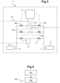
- the Figure 3 illustrates a second embodiment of the measuring station 1'.
- the first measurement solenoid valve 12 and the first conditioning solenoid valve 11 are connected to a sampling line L1.
- the at least second measurement solenoid valve 14a, 14b and the at least second conditioning solenoid valve 13a, 13b are connected to at least one sampling line L2, L3.
- sampling lines L1-L3 there are three sampling lines L1-L3, that is to say two second conditioning solenoid valves 13a, 13b arranged as a branch from the first conditioning solenoid valve 11 and from the inlet 7 of the packaging 3, and two second measurement solenoid valves 14a, 14b arranged as a branch from the first measurement solenoid valve 12 and from the inlet 9 of at least one gas analyzer 2.
- the two second measurement solenoid valves 14a, 14b and the two second conditioning solenoid valves 13a, 13b are connected to two respective sampling lines L2, L3.
- the measuring station 1' according to this second embodiment to comprise less than four second conditioning solenoid valves and less than four second measuring solenoid valves, the measuring station 1 being connected to at most five sampling lines L1-L5. Indeed, beyond five, the number of solenoid valves required increases the cost of the measuring station 1′ relatively significantly.
- a sampling line is conditioned, for example a single and unique sampling line, the measurement of which is programmed consecutively to a sampling line being measured while measuring in the sampling line with the at least a gas analyzer 2.
- the sampling line L3 is conditioned while the measurement is taken in the sampling line L2 with the at least one gas analyzer 2.
- the sequencing unit 4 controls the communication of the sampling line L3 with the conditioning pump 3 by opening the second sampling solenoid valve 13b of the sampling line L3, the second measurement solenoid valve 14b of the line sampling L3 being closed.
- the sequencing unit 4 controls the communication of the sampling line L2 with the at least one gas analyzer 2 by opening the second measurement solenoid valve 14a of the sampling line L2, the second sampling solenoid valve 13a being closed (step 101, Figure 4 ).
- the sequencing unit 4 controls the placing of the sampling line L3 in communication with the at least one gas analyzer 2 by opening the second measuring solenoid valve 14b of the sampling line L3 and by closing the second sampling solenoid valve 13b of the sampling line L3 and the second measuring solenoid valve 14a of the sampling line L2.
- the sequencing unit 4 controls the communication of the sampling line, a gaseous species concentration measurement of which must be carried out consecutively, with the conditioning pump 3 (step 102, Figure 4 ).
- Operations can continue in this way until all measurements defined in the sequencing program are performed in order. These operations can be repeated in a loop.
Landscapes
- Life Sciences & Earth Sciences (AREA)
- Health & Medical Sciences (AREA)
- Chemical & Material Sciences (AREA)
- Engineering & Computer Science (AREA)
- Pathology (AREA)
- Physics & Mathematics (AREA)
- Analytical Chemistry (AREA)
- Biochemistry (AREA)
- General Health & Medical Sciences (AREA)
- General Physics & Mathematics (AREA)
- Immunology (AREA)
- Molecular Biology (AREA)
- Biomedical Technology (AREA)
- Combustion & Propulsion (AREA)
- Food Science & Technology (AREA)
- Medicinal Chemistry (AREA)
- Sampling And Sample Adjustment (AREA)
Claims (8)
- Messstation (1; 1') zum Messen der luftgetragenen molekularen Verunreinigung, umfassend mindestens einen Gasanalysator (2) und eine Konditionierpumpe (3), umfassend ferner eine Sequenzierungseinheit (4), die ein Sequenzierungsprogramm umfasst, das eine Serienfolge der auszuführenden Messungen für mindestens zwei Entnahmeleitungen (L1-L16) definiert, wobei die Sequenzierungseinheit (4) dazu konfiguriert ist, das Herstellen der Verbindung einer zu messenden Entnahmeleitung (L1-L16), deren Messung folgend auf eine gerade gemessene Entnahmeleitung (L1-L16) programmiert ist, mit der Konditionierpumpe (3) während der Ansteuerung des Herstellens der Verbindung der gerade gemessenen Entnahmeleitung (L1-L16) mit dem mindestens einen Gasanalysator (2) anzusteuern, wobei die Messstation (1) dadurch gekennzeichnet ist, dass sie umfasst- ein Entnahmemagnetventil (5), das von der Sequenzierungseinheit (4) ansteuerbar ist, an jeder Entnahmeleitung (L1-L16),- ein erstes und ein zweites Konditioniermagnetventil (6a, 6b), die von der Sequenzierungseinheit (4) ansteuerbar sind und vom Einlass (7) der Konditionierpumpe (3) abzweigend angeordnet sind,- ein erstes und ein zweites Messmagnetventil (8a, 8b), die von der Sequenzierungseinheit (4) ansteuerbar sind und vom Einlass (9) des mindestens einen Gasanalysators (2) abzweigend angeordnet sind, wobei das erste Konditioniermagnetventil (6a) und das erste Messmagnetventil (8a) mit Entnahmemagnetventilen (5) einer ersten Serie (S1) von Entnahmeleitungen (L1, L3, L5, L7, L9, L11, L13, L15) verbunden sind, wobei das zweite Konditioniermagnetventil (6b) und das zweite Messmagnetventil (8b) mit Entnahmemagnetventilen (5) einer zweiten Serie (S2) von Entnahmeleitungen (L2, L4, L6, L8, L10, L12, L14, L16) verbunden sind.
- Messstation (1) nach dem vorhergehenden Anspruch, dadurch gekennzeichnet, dass die Sequenzierungseinheit (4) dazu konfiguriert ist, das Herstellen der Verbindung einer einzigen zu messenden Entnahmeleitung (L1-L16), deren Messung folgend auf eine gerade gemessene Entnahmeleitung (L1-L16) programmiert ist, mit der Konditionierpumpe (3) während der Ansteuerung des Herstellens der Verbindung der gerade gemessenen Entnahmeleitung (L1-L16) mit dem mindestens einen Gasanalysator (2) anzusteuern.
- Messstation (1) nach einem der vorhergehenden Ansprüche, dadurch gekennzeichnet, dass sie mindestens fünf Entnahmemagnetventile (5) umfasst.
- Messstation (1) nach einem der vorhergehenden Ansprüche, dadurch gekennzeichnet, dass die erste Serie (S1) von Entnahmeleitungen die gleiche Anzahl von Entnahmeleitungen wie die zweite Serie (S2) umfasst.
- Messstation (1) nach einem der vorhergehenden Ansprüche, dadurch gekennzeichnet, dass das Sequenzierungsprogramm eine Reihenfolge der auszuführenden Messungen definiert, bei der die auszuführenden Messungen in jeder Serie (S1, S2) von Entnahmeleitungen abwechseln.
- Messverfahren (100) zum Messen der luftgetragenen molekularen Verunreinigung mit einer Messstation (1; 1') nach einem der vorhergehenden Ansprüche, dadurch gekennzeichnet, dass man eine Entnahmeleitung (L1-L16), deren Messung folgend auf eine gerade gemessene Entnahmeleitung (L1-L16) programmiert ist, konditioniert, während man in der Entnahmeleitung (L1-L16) mit mindestens einem Gasanalysator (2) misst.
- Messverfahren (100) nach dem vorhergehenden Anspruch, dadurch gekennzeichnet, dass man die auszuführenden Messungen in jeder der beiden Serien (S1, S2) von Entnahmeleitungen abwechselt, wobei eine erste Serie (S1) von Entnahmeleitungen (L1, L3, L5, L7, L9, L11, L13, L15) mit einem ersten Konditioniermagnetventil (6a) und mit einem ersten Messmagnetventil (8a) verbunden ist, wobei eine zweite Serie (S2) von Entnahmeleitungen (L2, L4, L6, L8, L10, L12, L14, L16) mit einem zweiten Konditioniermagnetventil (6b) und mit einem zweiten Messmagnetventil (8b) verbunden ist.
- Messverfahren (100) nach einem der Ansprüche 6 oder 7, dadurch gekennzeichnet, dass die Entnahmeleitung (L1-L16), die konditioniert wird, während man in der Entnahmeleitung (L1-L16) mit mindestens einem Gasanalysator (2) misst, eine einzige ist.
Applications Claiming Priority (2)
| Application Number | Priority Date | Filing Date | Title |
|---|---|---|---|
| FR1800562A FR3081558B1 (fr) | 2018-05-28 | 2018-05-28 | Station et procede de mesure de la contamination moleculaire vehiculee par l'air |
| PCT/EP2019/063027 WO2019228844A1 (fr) | 2018-05-28 | 2019-05-21 | Station et procédé de mesure de la contamination moléculaire véhiculée par l'air |
Publications (2)
| Publication Number | Publication Date |
|---|---|
| EP3803323A1 EP3803323A1 (de) | 2021-04-14 |
| EP3803323B1 true EP3803323B1 (de) | 2022-03-23 |
Family
ID=63896215
Family Applications (1)
| Application Number | Title | Priority Date | Filing Date |
|---|---|---|---|
| EP19730689.7A Active EP3803323B1 (de) | 2018-05-28 | 2019-05-21 | Station und verfahren zur messung der molekularen kontamination in der luft |
Country Status (7)
| Country | Link |
|---|---|
| US (1) | US11768134B2 (de) |
| EP (1) | EP3803323B1 (de) |
| KR (1) | KR20210014682A (de) |
| CN (1) | CN112219101A (de) |
| FR (1) | FR3081558B1 (de) |
| TW (1) | TWI794498B (de) |
| WO (1) | WO2019228844A1 (de) |
Families Citing this family (5)
| Publication number | Priority date | Publication date | Assignee | Title |
|---|---|---|---|---|
| FR3108981B1 (fr) | 2020-04-01 | 2022-04-01 | Pfeiffer Vacuum Tech Ag | Station et procédé de mesure de la contamination moléculaire véhiculée par l’air |
| US11854845B2 (en) | 2020-09-16 | 2023-12-26 | Changxin Memory Technologies, Inc. | System for monitoring environment |
| CN114260262B (zh) * | 2020-09-16 | 2023-02-28 | 长鑫存储技术有限公司 | 环境监测系统 |
| EP4033245A1 (de) * | 2021-01-21 | 2022-07-27 | The Boeing Company | Fernluftsammlung |
| CN113588884B (zh) * | 2021-08-03 | 2023-08-15 | 亚翔系统集成科技(苏州)股份有限公司 | 一种基于amc在线监测系统的污染源查找方法 |
Family Cites Families (12)
| Publication number | Priority date | Publication date | Assignee | Title |
|---|---|---|---|---|
| US3043145A (en) * | 1958-06-10 | 1962-07-10 | Bailey Meter Co | Gas sample scanning apparatus |
| US4090392A (en) * | 1977-08-01 | 1978-05-23 | Ethyl Corporation | Automatic gas analyzer system |
| FR2795517B1 (fr) * | 1999-06-23 | 2002-10-18 | Air Liquide | Procede de pilotage d'un systeme d'analyse de gaz et systeme d'analyse pilote au moyen d'un tel procede |
| DE10018991A1 (de) * | 2000-04-17 | 2001-10-18 | Linde Gas Ag | Verfahren zur Meßgasanalyse |
| WO2008086606A1 (en) * | 2007-01-16 | 2008-07-24 | Dennis Scott Prince | Method and system for detecting and monitoring emissions |
| KR101027645B1 (ko) * | 2009-09-09 | 2011-04-12 | 주식회사 위드텍 | 샘플링 포트 클리닝 수단을 구비한 가스 모니터링 시스템 |
| CN201762404U (zh) * | 2010-08-31 | 2011-03-16 | 吕军 | 实现多个取样点自动连续清洁度检测时的装置 |
| US10139383B2 (en) | 2013-12-02 | 2018-11-27 | TricornTech Taiwan | Real-time air monitoring with multiple sensing modes |
| CN104090077B (zh) * | 2014-07-16 | 2015-09-02 | 中冶南方工程技术有限公司 | 一种带通道自检功能的多通道循环采样气体分析系统及控制方法 |
| CN205941107U (zh) * | 2016-07-15 | 2017-02-08 | 武汉钢铁股份有限公司 | 一种连续退火炉气体采样分析系统 |
| KR101782915B1 (ko) * | 2017-03-08 | 2017-09-29 | 주식회사 위드텍 | 개선된 샘플링 유로를 갖는 가스 모니터링 시스템 |
| CN108519254B (zh) | 2018-04-03 | 2021-04-06 | 力合科技(湖南)股份有限公司 | 采样流量控制装置及气体分析仪 |
-
2018
- 2018-05-28 FR FR1800562A patent/FR3081558B1/fr active Active
-
2019
- 2019-05-21 EP EP19730689.7A patent/EP3803323B1/de active Active
- 2019-05-21 CN CN201980036195.6A patent/CN112219101A/zh active Pending
- 2019-05-21 KR KR1020207037663A patent/KR20210014682A/ko not_active Application Discontinuation
- 2019-05-21 US US17/057,953 patent/US11768134B2/en active Active
- 2019-05-21 WO PCT/EP2019/063027 patent/WO2019228844A1/fr unknown
- 2019-05-23 TW TW108117788A patent/TWI794498B/zh active
Also Published As
| Publication number | Publication date |
|---|---|
| CN112219101A (zh) | 2021-01-12 |
| KR20210014682A (ko) | 2021-02-09 |
| US20210190647A1 (en) | 2021-06-24 |
| TW202012903A (zh) | 2020-04-01 |
| US11768134B2 (en) | 2023-09-26 |
| EP3803323A1 (de) | 2021-04-14 |
| FR3081558B1 (fr) | 2021-03-26 |
| TWI794498B (zh) | 2023-03-01 |
| WO2019228844A1 (fr) | 2019-12-05 |
| FR3081558A1 (fr) | 2019-11-29 |
Similar Documents
| Publication | Publication Date | Title |
|---|---|---|
| EP3803323B1 (de) | Station und verfahren zur messung der molekularen kontamination in der luft | |
| EP3345214B1 (de) | Verfahren und station zur messung der verschmutzung einer transportbox zur förderung und atmosphärischen lagerung von substraten | |
| EP1703547A2 (de) | Verfahren und Vorrichtung zur Kontrolle der Verunreinigung von Wafersubstraten | |
| EP2440915B1 (de) | Vorrichtung und verfahren zur gasanalyse | |
| FR3108981A1 (fr) | Station et procédé de mesure de la contamination moléculaire véhiculée par l’air | |
| FR2802335A1 (fr) | Systeme et procede de controle de minienvironnement | |
| CA2274736A1 (fr) | Installation d'analyse d'atmosphere | |
| EP0475246B1 (de) | Hochleistungsleckdetektor mit drei Molekularfiltern | |
| WO2020160910A1 (fr) | Procédé de réglage d'une station de mesure de la contamination moléculaire véhiculée par l'air et station de mesure | |
| WO2024061725A1 (fr) | Station de mesure d'une contamination moléculaire véhiculée par l'air | |
| EP1884761B1 (de) | Gasentnahme- und -analysesystem | |
| FR3139906A1 (fr) | Procédé et station de mesure d’une contamination moléculaire véhiculée par l’air | |
| EP2917716A1 (de) | Vorrichtung und verfahren zur schätzung einer gasströmung in einem gehäuse unter vermindertem druck in bezug auf das gas | |
| FR3141248A1 (fr) | Station et procédé de mesure de la contamination moléculaire véhiculée par l’air | |
| FR2873812A1 (fr) | Dispositif de prelevement de composes volatils | |
| FR3121962A1 (fr) | Pompe à vide | |
| FR3136550A1 (fr) | Procédé de détection de fuite amélioré et dispositif associé | |
| FR2946736A1 (fr) | Station et procede de sechage et/ou de degazage d'un produit ou d'une enceinte de transport pour le convoyage et le stockage atmospherique de substrats | |
| EP2843390A1 (de) | Verfahren zur Nachverfolgung der Ausgasungsrate durch Messung der Partialdrücke mit einem Massenspektrometer |
Legal Events
| Date | Code | Title | Description |
|---|---|---|---|
| STAA | Information on the status of an ep patent application or granted ep patent |
Free format text: STATUS: UNKNOWN |
|
| STAA | Information on the status of an ep patent application or granted ep patent |
Free format text: STATUS: THE INTERNATIONAL PUBLICATION HAS BEEN MADE |
|
| STAA | Information on the status of an ep patent application or granted ep patent |
Free format text: STATUS: THE INTERNATIONAL PUBLICATION HAS BEEN MADE |
|
| PUAI | Public reference made under article 153(3) epc to a published international application that has entered the european phase |
Free format text: ORIGINAL CODE: 0009012 |
|
| STAA | Information on the status of an ep patent application or granted ep patent |
Free format text: STATUS: REQUEST FOR EXAMINATION WAS MADE |
|
| 17P | Request for examination filed |
Effective date: 20201123 |
|
| AK | Designated contracting states |
Kind code of ref document: A1 Designated state(s): AL AT BE BG CH CY CZ DE DK EE ES FI FR GB GR HR HU IE IS IT LI LT LU LV MC MK MT NL NO PL PT RO RS SE SI SK SM TR |
|
| AX | Request for extension of the european patent |
Extension state: BA ME |
|
| DAV | Request for validation of the european patent (deleted) | ||
| DAX | Request for extension of the european patent (deleted) | ||
| RIN1 | Information on inventor provided before grant (corrected) |
Inventor name: LE BARILLEC, OLIVIER Inventor name: BOUNOUAR, JULIEN |
|
| GRAP | Despatch of communication of intention to grant a patent |
Free format text: ORIGINAL CODE: EPIDOSNIGR1 |
|
| STAA | Information on the status of an ep patent application or granted ep patent |
Free format text: STATUS: GRANT OF PATENT IS INTENDED |
|
| INTG | Intention to grant announced |
Effective date: 20211026 |
|
| GRAS | Grant fee paid |
Free format text: ORIGINAL CODE: EPIDOSNIGR3 |
|
| GRAA | (expected) grant |
Free format text: ORIGINAL CODE: 0009210 |
|
| STAA | Information on the status of an ep patent application or granted ep patent |
Free format text: STATUS: THE PATENT HAS BEEN GRANTED |
|
| AK | Designated contracting states |
Kind code of ref document: B1 Designated state(s): AL AT BE BG CH CY CZ DE DK EE ES FI FR GB GR HR HU IE IS IT LI LT LU LV MC MK MT NL NO PL PT RO RS SE SI SK SM TR |
|
| REG | Reference to a national code |
Ref country code: GB Ref legal event code: FG4D Free format text: NOT ENGLISH |
|
| REG | Reference to a national code |
Ref country code: CH Ref legal event code: EP |
|
| REG | Reference to a national code |
Ref country code: IE Ref legal event code: FG4D Free format text: LANGUAGE OF EP DOCUMENT: FRENCH |
|
| REG | Reference to a national code |
Ref country code: DE Ref legal event code: R096 Ref document number: 602019012845 Country of ref document: DE |
|
| REG | Reference to a national code |
Ref country code: AT Ref legal event code: REF Ref document number: 1477760 Country of ref document: AT Kind code of ref document: T Effective date: 20220415 |
|
| REG | Reference to a national code |
Ref country code: LT Ref legal event code: MG9D |
|
| REG | Reference to a national code |
Ref country code: NL Ref legal event code: MP Effective date: 20220323 |
|
| PG25 | Lapsed in a contracting state [announced via postgrant information from national office to epo] |
Ref country code: SE Free format text: LAPSE BECAUSE OF FAILURE TO SUBMIT A TRANSLATION OF THE DESCRIPTION OR TO PAY THE FEE WITHIN THE PRESCRIBED TIME-LIMIT Effective date: 20220323 Ref country code: RS Free format text: LAPSE BECAUSE OF FAILURE TO SUBMIT A TRANSLATION OF THE DESCRIPTION OR TO PAY THE FEE WITHIN THE PRESCRIBED TIME-LIMIT Effective date: 20220323 Ref country code: NO Free format text: LAPSE BECAUSE OF FAILURE TO SUBMIT A TRANSLATION OF THE DESCRIPTION OR TO PAY THE FEE WITHIN THE PRESCRIBED TIME-LIMIT Effective date: 20220623 Ref country code: LT Free format text: LAPSE BECAUSE OF FAILURE TO SUBMIT A TRANSLATION OF THE DESCRIPTION OR TO PAY THE FEE WITHIN THE PRESCRIBED TIME-LIMIT Effective date: 20220323 Ref country code: HR Free format text: LAPSE BECAUSE OF FAILURE TO SUBMIT A TRANSLATION OF THE DESCRIPTION OR TO PAY THE FEE WITHIN THE PRESCRIBED TIME-LIMIT Effective date: 20220323 Ref country code: BG Free format text: LAPSE BECAUSE OF FAILURE TO SUBMIT A TRANSLATION OF THE DESCRIPTION OR TO PAY THE FEE WITHIN THE PRESCRIBED TIME-LIMIT Effective date: 20220623 |
|
| REG | Reference to a national code |
Ref country code: AT Ref legal event code: MK05 Ref document number: 1477760 Country of ref document: AT Kind code of ref document: T Effective date: 20220323 |
|
| PG25 | Lapsed in a contracting state [announced via postgrant information from national office to epo] |
Ref country code: LV Free format text: LAPSE BECAUSE OF FAILURE TO SUBMIT A TRANSLATION OF THE DESCRIPTION OR TO PAY THE FEE WITHIN THE PRESCRIBED TIME-LIMIT Effective date: 20220323 Ref country code: GR Free format text: LAPSE BECAUSE OF FAILURE TO SUBMIT A TRANSLATION OF THE DESCRIPTION OR TO PAY THE FEE WITHIN THE PRESCRIBED TIME-LIMIT Effective date: 20220624 Ref country code: FI Free format text: LAPSE BECAUSE OF FAILURE TO SUBMIT A TRANSLATION OF THE DESCRIPTION OR TO PAY THE FEE WITHIN THE PRESCRIBED TIME-LIMIT Effective date: 20220323 |
|
| PG25 | Lapsed in a contracting state [announced via postgrant information from national office to epo] |
Ref country code: NL Free format text: LAPSE BECAUSE OF FAILURE TO SUBMIT A TRANSLATION OF THE DESCRIPTION OR TO PAY THE FEE WITHIN THE PRESCRIBED TIME-LIMIT Effective date: 20220323 |
|
| PG25 | Lapsed in a contracting state [announced via postgrant information from national office to epo] |
Ref country code: SM Free format text: LAPSE BECAUSE OF FAILURE TO SUBMIT A TRANSLATION OF THE DESCRIPTION OR TO PAY THE FEE WITHIN THE PRESCRIBED TIME-LIMIT Effective date: 20220323 Ref country code: SK Free format text: LAPSE BECAUSE OF FAILURE TO SUBMIT A TRANSLATION OF THE DESCRIPTION OR TO PAY THE FEE WITHIN THE PRESCRIBED TIME-LIMIT Effective date: 20220323 Ref country code: RO Free format text: LAPSE BECAUSE OF FAILURE TO SUBMIT A TRANSLATION OF THE DESCRIPTION OR TO PAY THE FEE WITHIN THE PRESCRIBED TIME-LIMIT Effective date: 20220323 Ref country code: PT Free format text: LAPSE BECAUSE OF FAILURE TO SUBMIT A TRANSLATION OF THE DESCRIPTION OR TO PAY THE FEE WITHIN THE PRESCRIBED TIME-LIMIT Effective date: 20220725 Ref country code: ES Free format text: LAPSE BECAUSE OF FAILURE TO SUBMIT A TRANSLATION OF THE DESCRIPTION OR TO PAY THE FEE WITHIN THE PRESCRIBED TIME-LIMIT Effective date: 20220323 Ref country code: EE Free format text: LAPSE BECAUSE OF FAILURE TO SUBMIT A TRANSLATION OF THE DESCRIPTION OR TO PAY THE FEE WITHIN THE PRESCRIBED TIME-LIMIT Effective date: 20220323 Ref country code: CZ Free format text: LAPSE BECAUSE OF FAILURE TO SUBMIT A TRANSLATION OF THE DESCRIPTION OR TO PAY THE FEE WITHIN THE PRESCRIBED TIME-LIMIT Effective date: 20220323 Ref country code: AT Free format text: LAPSE BECAUSE OF FAILURE TO SUBMIT A TRANSLATION OF THE DESCRIPTION OR TO PAY THE FEE WITHIN THE PRESCRIBED TIME-LIMIT Effective date: 20220323 |
|
| PG25 | Lapsed in a contracting state [announced via postgrant information from national office to epo] |
Ref country code: PL Free format text: LAPSE BECAUSE OF FAILURE TO SUBMIT A TRANSLATION OF THE DESCRIPTION OR TO PAY THE FEE WITHIN THE PRESCRIBED TIME-LIMIT Effective date: 20220323 Ref country code: IS Free format text: LAPSE BECAUSE OF FAILURE TO SUBMIT A TRANSLATION OF THE DESCRIPTION OR TO PAY THE FEE WITHIN THE PRESCRIBED TIME-LIMIT Effective date: 20220723 Ref country code: AL Free format text: LAPSE BECAUSE OF FAILURE TO SUBMIT A TRANSLATION OF THE DESCRIPTION OR TO PAY THE FEE WITHIN THE PRESCRIBED TIME-LIMIT Effective date: 20220323 |
|
| REG | Reference to a national code |
Ref country code: CH Ref legal event code: PL |
|
| REG | Reference to a national code |
Ref country code: DE Ref legal event code: R097 Ref document number: 602019012845 Country of ref document: DE |
|
| REG | Reference to a national code |
Ref country code: BE Ref legal event code: MM Effective date: 20220531 |
|
| PLBE | No opposition filed within time limit |
Free format text: ORIGINAL CODE: 0009261 |
|
| STAA | Information on the status of an ep patent application or granted ep patent |
Free format text: STATUS: NO OPPOSITION FILED WITHIN TIME LIMIT |
|
| PG25 | Lapsed in a contracting state [announced via postgrant information from national office to epo] |
Ref country code: MC Free format text: LAPSE BECAUSE OF FAILURE TO SUBMIT A TRANSLATION OF THE DESCRIPTION OR TO PAY THE FEE WITHIN THE PRESCRIBED TIME-LIMIT Effective date: 20220323 Ref country code: LU Free format text: LAPSE BECAUSE OF NON-PAYMENT OF DUE FEES Effective date: 20220521 Ref country code: LI Free format text: LAPSE BECAUSE OF NON-PAYMENT OF DUE FEES Effective date: 20220531 Ref country code: DK Free format text: LAPSE BECAUSE OF FAILURE TO SUBMIT A TRANSLATION OF THE DESCRIPTION OR TO PAY THE FEE WITHIN THE PRESCRIBED TIME-LIMIT Effective date: 20220323 Ref country code: CH Free format text: LAPSE BECAUSE OF NON-PAYMENT OF DUE FEES Effective date: 20220531 |
|
| 26N | No opposition filed |
Effective date: 20230102 |
|
| PG25 | Lapsed in a contracting state [announced via postgrant information from national office to epo] |
Ref country code: IE Free format text: LAPSE BECAUSE OF NON-PAYMENT OF DUE FEES Effective date: 20220521 |
|
| PG25 | Lapsed in a contracting state [announced via postgrant information from national office to epo] |
Ref country code: SI Free format text: LAPSE BECAUSE OF FAILURE TO SUBMIT A TRANSLATION OF THE DESCRIPTION OR TO PAY THE FEE WITHIN THE PRESCRIBED TIME-LIMIT Effective date: 20220323 Ref country code: BE Free format text: LAPSE BECAUSE OF NON-PAYMENT OF DUE FEES Effective date: 20220531 |
|
| PG25 | Lapsed in a contracting state [announced via postgrant information from national office to epo] |
Ref country code: IT Free format text: LAPSE BECAUSE OF FAILURE TO SUBMIT A TRANSLATION OF THE DESCRIPTION OR TO PAY THE FEE WITHIN THE PRESCRIBED TIME-LIMIT Effective date: 20220323 |
|
| PGFP | Annual fee paid to national office [announced via postgrant information from national office to epo] |
Ref country code: FR Payment date: 20230523 Year of fee payment: 5 Ref country code: DE Payment date: 20230525 Year of fee payment: 5 |
|
| GBPC | Gb: european patent ceased through non-payment of renewal fee |
Effective date: 20230521 |
|
| PG25 | Lapsed in a contracting state [announced via postgrant information from national office to epo] |
Ref country code: MK Free format text: LAPSE BECAUSE OF FAILURE TO SUBMIT A TRANSLATION OF THE DESCRIPTION OR TO PAY THE FEE WITHIN THE PRESCRIBED TIME-LIMIT Effective date: 20220323 Ref country code: CY Free format text: LAPSE BECAUSE OF FAILURE TO SUBMIT A TRANSLATION OF THE DESCRIPTION OR TO PAY THE FEE WITHIN THE PRESCRIBED TIME-LIMIT Effective date: 20220323 Ref country code: GB Free format text: LAPSE BECAUSE OF NON-PAYMENT OF DUE FEES Effective date: 20230521 |