EP3803045B1 - Auskleidungsanlage mit aufblasbarem packer - Google Patents
Auskleidungsanlage mit aufblasbarem packer Download PDFInfo
- Publication number
- EP3803045B1 EP3803045B1 EP19728293.2A EP19728293A EP3803045B1 EP 3803045 B1 EP3803045 B1 EP 3803045B1 EP 19728293 A EP19728293 A EP 19728293A EP 3803045 B1 EP3803045 B1 EP 3803045B1
- Authority
- EP
- European Patent Office
- Prior art keywords
- inflatable packer
- liner
- deformable liner
- wellbore
- tool
- Prior art date
- Legal status (The legal status is an assumption and is not a legal conclusion. Google has not performed a legal analysis and makes no representation as to the accuracy of the status listed.)
- Active
Links
Images








Classifications
-
- E—FIXED CONSTRUCTIONS
- E21—EARTH OR ROCK DRILLING; MINING
- E21B—EARTH OR ROCK DRILLING; OBTAINING OIL, GAS, WATER, SOLUBLE OR MELTABLE MATERIALS OR A SLURRY OF MINERALS FROM WELLS
- E21B43/00—Methods or apparatus for obtaining oil, gas, water, soluble or meltable materials or a slurry of minerals from wells
- E21B43/02—Subsoil filtering
- E21B43/10—Setting of casings, screens, liners or the like in wells
- E21B43/103—Setting of casings, screens, liners or the like in wells of expandable casings, screens, liners, or the like
- E21B43/108—Expandable screens or perforated liners
-
- E—FIXED CONSTRUCTIONS
- E21—EARTH OR ROCK DRILLING; MINING
- E21B—EARTH OR ROCK DRILLING; OBTAINING OIL, GAS, WATER, SOLUBLE OR MELTABLE MATERIALS OR A SLURRY OF MINERALS FROM WELLS
- E21B43/00—Methods or apparatus for obtaining oil, gas, water, soluble or meltable materials or a slurry of minerals from wells
- E21B43/02—Subsoil filtering
- E21B43/10—Setting of casings, screens, liners or the like in wells
- E21B43/103—Setting of casings, screens, liners or the like in wells of expandable casings, screens, liners, or the like
- E21B43/105—Expanding tools specially adapted therefor
-
- E—FIXED CONSTRUCTIONS
- E21—EARTH OR ROCK DRILLING; MINING
- E21B—EARTH OR ROCK DRILLING; OBTAINING OIL, GAS, WATER, SOLUBLE OR MELTABLE MATERIALS OR A SLURRY OF MINERALS FROM WELLS
- E21B23/00—Apparatus for displacing, setting, locking, releasing or removing tools, packers or the like in boreholes or wells
- E21B23/06—Apparatus for displacing, setting, locking, releasing or removing tools, packers or the like in boreholes or wells for setting packers
-
- E—FIXED CONSTRUCTIONS
- E21—EARTH OR ROCK DRILLING; MINING
- E21B—EARTH OR ROCK DRILLING; OBTAINING OIL, GAS, WATER, SOLUBLE OR MELTABLE MATERIALS OR A SLURRY OF MINERALS FROM WELLS
- E21B33/00—Sealing or packing boreholes or wells
- E21B33/10—Sealing or packing boreholes or wells in the borehole
- E21B33/12—Packers; Plugs
- E21B33/127—Packers; Plugs with inflatable sleeve
-
- E—FIXED CONSTRUCTIONS
- E21—EARTH OR ROCK DRILLING; MINING
- E21B—EARTH OR ROCK DRILLING; OBTAINING OIL, GAS, WATER, SOLUBLE OR MELTABLE MATERIALS OR A SLURRY OF MINERALS FROM WELLS
- E21B43/00—Methods or apparatus for obtaining oil, gas, water, soluble or meltable materials or a slurry of minerals from wells
- E21B43/02—Subsoil filtering
- E21B43/10—Setting of casings, screens, liners or the like in wells
- E21B43/103—Setting of casings, screens, liners or the like in wells of expandable casings, screens, liners, or the like
Definitions
- This disclosure relates to using inflatable packers within a wellbore.
- An inflatable packer is a type of packer that uses an inflatable bladder to expand the packer element against a casing or wellbore. A drop ball or a series of tubing movements are sometimes necessary to prepare for setting the inflatable packer.
- Inflatable packers can be inflated using hydraulic pressure provided, for example, by applying pump pressure. Inflatable packers are capable of relatively large expansion ratios, which can be useful in through-tubing work where the tubing size or completion components can impose a size restriction on devices designed to set in the casing or liner below the tubing.
- US 3,175,618 considered the closest prior art, describes an apparatus for expanding a metal liner with explosives to produce a fluid-tight fit of the liner against the inside of a vessel.
- JP 2010 156172 describes an outer pipe packer is a water-impermeable expansion and contraction packer and is expanded by a fluid filled in the outer pipe packer via an injection inner pipe from an outer-pipe-packer-inside discharge opening which is covered with a check valve and is provided on the pipe wall of an injection outer pipe in the outer pipe packer.
- the inner pipe has a plurality of inner pipe packers, while a pipe wall in the inner pipe packer has pipe-packer-inside discharge opening.
- inner pipe discharge openings are provided in the inner-pipe pipe-wall among the plurality of inner pipe packers.
- the plurality of inner pipe packers are loosely inserted in the outer pipe in such a way as to be positioned on both sides of the outer-pipe-inside discharge opening.
- CN 201496028 (U ) describes an inner pipe series tool external inflatable casing packer in the oil well completion field.
- a well tool is positioned within a wellbore.
- the well tool has an initial outer diameter before the well tool is positioned within the wellbore.
- the well tool includes a deformable liner, a first inflatable packer positioned within the deformable liner, and a second inflatable packer positioned around the deformable liner.
- the first inflatable packer is inflated to deform the deformable liner, such that an inner liner diameter of the deformable liner, after the deformable liner is deformed, is equal to or greater than the initial outer diameter of the well tool.
- the second inflatable packer is inflated to sealably contact an inner wall of the wellbore.
- the well tool includes an inflation tool coupled to each of the first inflatable packer and the second inflatable packer, independently.
- the inflation tool is configured to convey hydraulic pressure to inflate each of the first inflatable packer and the second inflatable packer, independently.
- the well tool includes a tubular connection connecting the inflation tool to the second inflatable packer before the well tool is positioned within the wellbore.
- the tubular connection is configured to allow fluid communication between the inflation tool and the second inflatable packer.
- the well tool includes a backflow prevention device connected to the tubular connection.
- the backflow prevention device is positioned closer to the second inflatable packer than to the inflation tool.
- the backflow prevention device is configured to allow fluid to flow through the backflow prevention device from the inflation to the second inflatable packer.
- the backflow prevention device is configured to prevent fluid from flowing through the backflow prevention device from the second inflatable packer to the inflation tool.
- the tubular connection includes an engineered weak point positioned along the tubular connection closer to the second inflatable packer than to the inflation tool.
- the tubular connection is configured to break at the engineered weak point in response to an application of tension strain on the tubular connection.
- the first inflatable packer After inflating the first inflatable packer, the first inflatable packer can be removed from within the deformable liner.
- Inflating the second inflatable packer can include flowing a hardening fluid into the second inflatable packer. Inflating the second inflatable packer can include allowing the hardening fluid to solidify within the second inflatable packer, such that the second inflatable packer remains permanently inflated.
- the inflation tool After inflating the second inflatable packer, the inflation tool can be moved away from the second inflatable packer, such that the tubular connection breaks at the engineered weak point. After inflating the second inflatable packer, the inflation tool can be removed from within the wellbore.
- the deformable liner can include a first slotted end and a second slotted end opposite the first slotted end.
- the first slotted end can be flared radially outward.
- the second slotted end can be flared radially outward.
- a piece of equipment can be guided to the deformable liner with the flared first slotted end or the flared second slotted end.
- a ratio of the inner liner diameter after the deformable liner is deformed to the inner liner diameter before the deformable liner is deformed can be in a range of approximately 1.02 to approximately 3.
- the well tool includes a deformable liner configured to be positioned within a wellbore.
- the deformable liner is configured to be deformed radially.
- the well tool includes a first inflatable packer configured to be positioned within the deformable liner.
- the first inflatable packer is configured to be inflated while positioned within the deformable liner to deform the deformable liner radially.
- the well tool includes a second inflatable packer configured to be positioned around the deformable liner.
- the second inflatable packer is configured to be inflated to an inner wall of the wellbore.
- the well tool includes an inflation tool fluidically coupled to each of the first inflatable packer and the second inflatable packer, independently.
- the inflation tool is configured to convey hydraulic pressure to inflate each of the first inflatable packer and the second inflatable packer, independently.
- the well tool includes a tubular connection connecting the inflation tool to the second inflatable packer before the well tool is positioned within the wellbore.
- the tubular connection is configured to allow fluid communication between the inflation tool and the second inflatable packer.
- the well tool includes a backflow prevention device connected to the tubular connection.
- the backflow prevention device is positioned closer to the second inflatable packer than to the inflation tool.
- the backflow prevention device is configured to allow fluid to flow through the backflow prevention device from the inflation tool to the second inflatable packer.
- the backflow prevention device is configured to prevent fluid from flowing through the backflow prevention device from the second inflatable packer to the inflation tool.
- the tubular connection includes an engineered weak point positioned along the tubular connection closer to the second inflatable packer than to the inflation tool.
- the tubular connection is configured to break at the engineered weak point in response to an application of tension strain on the tubular connection.
- the second inflatable packer before being inflated, can define an initial outer diameter of the well tool.
- the first inflatable packer can be configured to be inflated while positioned within the deformable liner to deform the deformable liner radially, such that the deformable liner, after being deformed radially, defines an inner liner diameter that is greater than the initial outer diameter of the well tool.
- the deformable liner can define an inner liner diameter.
- the deformable liner can be configured to be deformed radially, such that a ratio of the inner liner diameter after being deformed radially to the inner liner diameter before being deformed radially is in a range of approximately 1.02 to approximately 3.
- a liner can be installed within a wellbore, so that additional equipment can be run and deployed in the well.
- Using a deformable liner allows for the inner diameter to be tailored to the equipment to be installed within the wellbore.
- Using a deformable liner allows for the liner to be installed within the wellbore without introducing a new (smaller) restriction in the well.
- the deformable liner can be expanded, such that the inner liner diameter of the deformable liner is equal to or greater than the smallest existing inner diameter in the well (such as the production tubing).
- the deformable liner can include slotted ends, which can flare out radially to form flared ends.
- the flared ends of the deformable liner can contact an inner wall of the well bore, and the flared ends can aid intervention of tool strings through the expanded deformable liner.
- the flared ends of the deformable liner can support and center the liner within the wellbore.
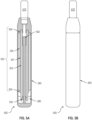
- FIG. 1A shows a cross-sectional view of a well tool 100.
- FIG. 1B shows an external view of the well tool 100.
- the well tool 100 includes a deformable liner 101, a first inflatable packer 103, and a second inflatable packer 105.
- the deformable liner 101 is configured to be positioned within a wellbore (an example wellbore 201 is shown in FIG. 2A ).
- the first inflatable packer 103 is configured to be positioned within the deformable liner 101.
- the second inflatable packer 105 is configured to be positioned around the deformable liner 101.
- the well tool 100 can include an inflation tool 170.
- the inflation tool 170 is coupled to the first inflatable packer 103 and to the second inflatable packer 105, independently.
- the deformable liner 101 can have a tubular shape.
- the deformable liner 101 is configured to be deformed radially. Therefore, an inner liner diameter of the deformable liner 101 can be altered.
- the inner liner diameter of the deformable liner 101 can be increased by applying pressure in an outwardly radial direction to an inner surface of the deformable liner 101.
- a substantially equal amount of pressure can be applied in all radial directions.
- the deformable liner 101 can be deformed, such that a ratio of an inner liner diameter after the deformable liner 101 is deformed to an inner liner diameter before the deformable liner 101 is deformed is in a range of approximately 1.02 to approximately 3.
- the deformable liner 101 can be deformed, such that its final inner liner diameter after deformation is approximately 2 times its initial liner diameter before deformation.
- the deformable liner 101 can be deformed, such that a ratio of an inner liner diameter after the deformable liner 101 is deformed to an inner liner diameter before the deformable liner 101 is deformed is in a range of approximately 1.02 to approximately 2, approximately 1.02 to approximately 1.9, approximately 1.02 to approximately 1.75, or approximately 1.02 to approximately 1.5.
- the outer liner diameter of the deformable liner 101 can also expand.
- the thickness (that is, the difference between the outer diameter and the inner diameter) of the deformable liner 101 may decrease.
- Non-limiting examples of suitable materials for the deformable liner 101 are metals or metallic materials, such as stainless steel (for example, 304L class stainless steel), Inconel Alloy 625 (Unified Numbering System N06625), and Alloy C276 (Unified Numbering System N10276).
- the deformable liner 101 is made of a material that is corrosion resistant.
- the deformable liner 101 remains corrosion resistant after plastic deformation.
- the deformable liner 101 includes a thermoplastic polymer, such as polyether ether ketone. Examples of the deformable liner 101 are also shown in FIGs. 1C and 1D and are described in more detail.
- the first inflatable packer 103 is configured to inflate while positioned within the deformable liner 101.
- the first inflatable packer 103 can be expanded radially. Because the first inflatable packer 103 is positioned within the deformable liner 101, a radial expansion of the first inflatable packer 103 causes the deformable liner 101 to deform (for example, expand) radially.
- a longitudinal length of the first inflatable packer 103 can be at least equal to a longitudinal length of the deformable liner 101.
- the first inflatable packer 103 can have a shape of a pouch or sleeve. In some implementations, the first inflatable packer 103 can have an elongated toroidal shape.
- Suitable materials for the first inflatable packer 103 can endure pressures greater than a deformation pressure of the deformable liner 101 (that is, a pressure at which the deformable liner 101 deforms), allowing the first inflatable packer 103 to apply radial pressure across an inner surface of the deformable liner 101 and effectively deform the deformable liner 101 without rupturing the first inflatable packer 103.
- the first inflatable packer 103 is designed to withstand pressures of 34 MPa (5,000 pounds per square inch (psi)) or more without rupturing.
- a non-limiting example of a suitable material for the first inflatable packer 103 is reinforced rubber.
- the first inflatable packer 103 has a tubular shape with pressure connections (for example, steel pressure connections) on both ends of the first inflatable packer 103 (similar to a hydraulic hose).
- the first inflatable packer 103 includes layers of rubber and reinforcement layers of fabric.
- the first inflatable packer 103 When positioned within the deformable liner 101, the first inflatable packer 103 can be inflated to deform the deformable liner 101.
- the first inflatable packer 103 can be inflated by flowing fluid from the inflation tool 170 to the first inflatable packer 103.
- the fluid flowed into the first inflatable packer 103 can be any fluid that is compatible with the first inflatable packer 103; that is, the fluid flowed into the first inflatable packer 103 does not degrade or otherwise react with the material that makes up the first inflatable packer 103.
- Some non-limiting examples of fluid that can be flowed into the first inflatable packer 103 to inflate the first inflatable packer 103 include water, oil, gas, or any combination of these.
- the first inflatable packer 103 By inflating the first inflatable packer 103 while the first inflatable packer 103 is positioned within the deformable liner 101, pressure is applied in an outwardly radial direction on the deformable liner 101, thereby causing the deformable liner 101 to deform radially.
- the deformation of the deformable liner 101 can also cause the second packer 105 to deform, shift, or move, without the second packer 105 being inflated with another fluid.
- the inflation of the first inflatable packer 103 is volume controlled, in order to accurately and precisely control the expansion of the deformable liner 101.
- the first inflatable packer 103 should inflate, such that the deformable liner 101 expands to a point at which the inner liner diameter of the expanded deformable liner 101 is equal to or greater than an initial outer diameter of the well tool 100 (for example, before the well tool 100 is positioned within a wellbore) and also at which the deformable liner 101 does not rupture.
- the expanded deformable liner 101 has an inner liner diameter that is equal to or greater than an inner diameter of the smallest existing restriction of the well, such as the production tubing or a nipple profile.
- the second inflatable packer 105 is configured to be inflated to an inner wall of the wellbore.
- a longitudinal length of the second inflatable packer 105 can be at least equal to the longitudinal length of the deformable liner 101.
- the second inflatable packer 105 can have a shape of a pouch or sleeve. In some implementations, the second inflatable packer 105 can have an elongated toroidal shape.
- the second inflatable packer 105 can define an inner volume defined by its toroidal shape, within which the deformable liner 101 can be placed, such that the second inflatable packer 105 surrounds the deformable liner 101. Before being inflated, the second inflatable packer 105 can define an initial outer diameter of the well tool 100.
- the first inflatable packer 103 can inflate while positioned within the deformable liner 101 to deform the deformable liner 101 radially, such that the deformable liner 101 (after being deformed radially) defines an inner liner diameter that is greater than the initial outer diameter of the well tool 100.
- a non-limiting example of a suitable material for the second inflatable packer 105 is reinforced rubber.
- the second inflatable packer 105 is made of a composite material, such as a mineral reinforced with an elastomeric material.
- the second inflatable packer 105 is made of a non-elastic material that can be folded and wrapped around the deformable liner 101, and the second inflatable packer 105 is configured to unfold and inflate after the first inflatable packer 103 has inflated and deformed the deformable liner 101.
- the second inflatable packer 105 is made of an elastic material that can stretch as the second inflatable packer 105 is inflated. The second inflatable packer 105 can be resistant to rupture and abrasion.
- the second inflatable packer 105 includes fabric sheets of reinforcement material, such as fiber glass or a synthetic textile (for example, made of Aramid fiber) covered or coated with rubber. In some implementations, the second inflatable packer 105 is designed to withstand pressures of 500 kPa (75 psi) or more.
- the second inflatable packer 105 When positioned around the deformable liner 101, the second inflatable packer 105 can be inflated to contact an inner wall of the wellbore (an example of the inner wall 250 is shown in FIG. 2B ). The expansion of the second inflatable packer 105 can create a seal between an outer surface of the second inflatable packer 105 and the inner wall of the wellbore and also between the outer surface of the second inflatable packer 105 and an outer surface of the deformable liner 101. Fluid can be flowed from the inflation tool 170 to the second inflatable packer 105 in order to inflate the second inflatable packer 105.
- the first inflatable packer 103 can continue to apply pressure on the inner surface of the deformable liner 101 to counter the pressure being applied by the second inflatable packer 105 on the outer surface of the deformable liner 101.
- the pressure from the first inflatable packer 103 can prevent the deformable liner 101 from being deformed radially inward (that is, contract), while the second inflatable packer 105 inflates.
- the first inflatable packer 103 is deflated (or the pressure being applied to the first inflatable packer 103 is removed) before the second inflatable packer 105 is inflated.
- the pressure applied by the second inflatable packer 105 on the outer surface of the deformable liner 101, as the second inflatable packer 105 inflates, is less than the deformation force necessary to radially reduce the diameter of the deformable liner 101. Therefore, after the deformable liner 101 has been expanded by the first inflatable packer 103, the first inflatable packer 103 can be deflated, and the second inflatable packer 105 can be inflated without causing the deformable liner 101 to contract.
- the fluid flowed into the second inflatable packer 105 can be a hardening fluid that is compatible with the second inflatable packer 105; that is, the hardening fluid flowed into the second inflatable packer 105 does not degrade or otherwise react with the material that makes up the second inflatable packer 105.
- the hardening fluid can be a liquid substance that irreversibly solidifies.
- the hardening fluid can be in a liquid state until hardening of the hardening liquid is desired. For example, the hardening fluid can remain in a liquid state while the hardening fluid is being flowed into the second inflatable packer 105 to inflate the second inflatable packer 105.
- the hardening fluid begins to solidify due a temperature of the wellbore (for example, a temperature-sensitive material, such as a thermoset). In some implementations, the hardening fluid begins to solidify after a certain time period (for example, a cement or synthetic resin). In some implementations, the hardening fluid begins to solidify after a curing or cross-linking agent is introduced (for example, a curing epoxy resin). After flowing the hardening fluid to the second inflatable packer 105 to inflate and contact the wellbore, the hardening fluid within the second inflatable packer 105 can solidify, so that the position of the deformable liner 101 relative to the wellbore can be retained.
- a temperature of the wellbore for example, a temperature-sensitive material, such as a thermoset.
- the hardening fluid begins to solidify after a certain time period (for example, a cement or synthetic resin).
- the hardening fluid begins to solidify after a curing or cross-linking agent is introduced (for example,
- Solidifying the hardening fluid in the second inflatable packer 105 can secure the deformable liner 101 to the wellbore.
- the hardening fluid includes an expanding additive configured to expand after the second inflatable packer 105 has been inflated, such that while the hardening fluid solidifies within the second inflatable packer 105, the expanding additive increases the contact force between the second inflatable packer 105 and the wellbore and the contact force between the second inflatable packer 105 and the deformable liner 101.
- the increased contact forces can increase the capability of the second inflatable packer 105 to anchor the deformable liner 101 within the wellbore.
- the increased contact forces can increase the capability of the second inflatable packer 105 to create a seal with the inner wall of the wellbore.
- the deformable liner 101 can include slotted ends 104 at both ends of the deformable liner 101.
- the slotted ends 104 can flare radially outward.
- FIGs. 1C and 1D show examples of the deformable liner 101 with the slotted ends before flaring radially outward (104a) and the slotted ends flared radially outward (104b).
- the flared ends (104b) can support and center the deformable liner 101 within a wellbore.
- the slotted ends 104 can be flared out, for example, by inflating the first inflatable packer 103 positioned within the deformable liner 101.
- the slotted ends 104 are coupled to the second inflatable packer 105.
- the slotted ends 104 can be strapped to the second inflatable packer 105, such that when the second inflatable packer 105 (surrounding the deformable liner 101) is inflated, the slotted ends 104 flare out, toward the second inflatable packer 105.
- the flaring angle ⁇ is in a range of approximately 5° to approximately 170°.
- FIGs. 1E and 1F show examples of the inflation tool 170 and the second inflatable packer 105.
- the inflation tool 170 is configured to convey hydraulic pressure to inflate the first inflatable packer 103 and the second inflatable packer 105, independently. Fluids can be flowed through the inflation tool 170 to each of the first and second inflatable packers (103, 105) using, for example, one or more pumps.
- the inflation tool 170 can be connected to the one or more pumps by, for example, a hydraulic tether (such as coiled tubing).
- the inflation tool 170 includes a tubular connection 171 connecting the inflation tool 170 to the second inflatable packer 105 (for example, before the well tool 100 is positioned within a wellbore).
- the tubular connection 171 is configured to allow fluid communication between the inflation tool 170 and the second inflatable packer 105.
- the inflation tool 170 can also include another tubular connection connecting the inflation tool 170 to the first inflatable packer 103 to allow fluid communication between the inflation tool 170 and the first inflatable packer 103.
- the inflation tool 170 includes a first compartment with fluid for inflating the first inflatable packer 103 and a second compartment with fluid (such as hardening fluid) for inflating the second inflatable packer 105.
- the first compartment and second compartment of the inflation tool 170 can be operated similarly to, for example, hydraulic cylinders.
- Each of the first compartment and the second compartment of the inflation tool 170 can include pistons, which can be actuated, for example, by the one or more pumps connected to the inflation tool 170 by a hydraulic tether.
- Actuating the piston of the first compartment can pressurize the fluid within the first compartment and cause the fluid to flow into the first inflatable packer 103, thereby causing the first inflatable packer 103 to inflate.
- Actuating the piston of the second compartment can pressurize the fluid within the second compartment and cause the fluid to flow into the second inflatable packer 105 (through the tubular connection 171), thereby causing the second inflatable packer 105 to inflate.
- the fluids that are flowed into the first inflatable packer 103 and the second inflatable packer 105 can be flowed from the surface (for example, from a wellhead pump) through the inflation tool 170.
- the inflation tool 170 can be configured to provide a predetermined amount of fluid to the first inflatable packer 103.
- the piston of the first compartment can have a predetermined length corresponding to the predetermined amount of fluid or the piston can be configured to be actuated for a predetermined length corresponding to the predetermined amount of fluid for the first inflatable packer 103.
- a valve of the inflation tool 170 is actuated to prevent more fluid from entering the first inflatable packer after the predetermined amount of fluid is flowed into the first inflatable packer 103.
- the tubular connection 171 can include a backflow prevention device 172 (such as a check valve). As shown in FIGs. 1E and 1F , the backflow prevention device 172 can be located within the second inflatable packer 105. The backflow prevention device 172 is configured to allow fluid to flow through the backflow prevention device 172 from the inflation tool 170 (and through the tubular connection 171) to the second inflatable packer 105. The backflow prevention device 172 is configured to prevent fluid from flowing through the backflow prevention device 172 from the second inflatable packer 105 to the inflation tool 170.
- the tubular connection 171 includes an engineered weak point 173 positioned along the tubular connection 171 closer to the second inflatable packer 105 than to the inflation tool 170.
- the engineered weak point 173 is located along the tubular connection 171 upstream of the backflow prevention device 172.
- the tubular connection 171 is configured to break at the engineered weak point 173 in response to an application of tension strain on the tubular connection 171. It is desirable for the engineered weak point 173 to be as close to the second inflatable packer 105 as possible to minimize the amount of the tubular connection 171 left connected to the second inflatable packer 105 after the tubular connection 171 has been broken at the engineered weak point 173.
- FIG. 1E shows the inflation tool 170 connected to the second inflatable packer 105 with an intact tubular connection 171.
- FIG. 1F shows the inflation tool 170 disconnected from the second inflatable packer 105, after the inflation tool 170 has been moved away from the second inflatable packer 105, thereby applying a tension strain on the tubular connection 171, causing the tubular connection 171 to break at the engineered weak point 173. Even after the tubular connection 171 has broken, the backflow prevention device 172 prevents fluid from flowing out of the second inflatable packer 105 through the broken tubular connection 171.
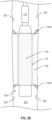
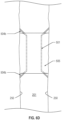
- FIGs. 2A , 2B , and 2C show the well tool 100 positioned within a wellbore 201.
- the wellbore 201 shown in FIGs. 2A , 2B , and 2C is vertical, the well tool 100 can be positioned and used within a wellbore that has any orientation, such as horizontal or otherwise at any other angle that deviates from a vertical orientation.
- the initial outer diameter of the well tool 100, including the second inflatable packer 105 before the well tool 100 is positioned within the wellbore 201 (and before the first inflatable packer 103 is inflated to deform the deformable liner 101) is smaller than the smallest existing restriction in the well (along a longitudinal axis of the wellbore 201), so that the well tool 100 can travel through the well to the desired location within the wellbore 201.
- fluid can be flowed to the first inflatable packer 103 (for example, with the inflation tool 170) to inflate the first inflatable packer 103 and radially deform the deformable liner 101.
- the first inflatable packer 103 can be inflated, such that the deformable liner 101 is expanded radially to increase the inner liner diameter to at least equal to (or greater than) the initial outer diameter of the well tool 100 (as shown in FIG. 2B ).
- fluid such as the hardening fluid
- the second inflatable packer 105 for example, with the inflation tool 170
- the slotted ends 104 can flare radially outward (104b) and contact the inner wall 250 of the wellbore 201.
- the hardening fluid can be allowed to solidify within the second inflatable packer 105 in order to maintain the position of the deformable liner 101 relative to the wellbore 201.
- the first inflatable packer 103 can be deflated and removed from the wellbore 201. Because the inner liner diameter is increased to at least equal to the initial outer diameter of the well tool 100, the remaining portions of the well tool 100 (excluding the deformable liner 101 and the second inflatable packer 105) can be removed from the wellbore 201 through the (now expanded) deformable liner 101 itself. The remaining portions (such as the inflation tool 170) can also be removed from the wellbore 201 through the expanded deformable liner 101. Removing the inflation tool 170 can include moving the inflation tool 170 away from the second inflatable packer 105, causing the tubular connection 171 to break at the engineered weak point 173.
- the deformable liner 101 with increased inner liner diameter (with flared slotted ends 104b) and inflated second inflatable packer 105 can securely stay put within the wellbore 201 (as shown in FIG. 2C ) for additional equipment to be installed within the wellbore 201.
- FIG. 3 is a flow chart for a method 300.
- a well tool such as the well tool 100
- a wellbore such as the wellbore 201
- a first inflatable packer (103) positioned within a deformable liner (101) is inflated to deform the deformable liner 101.
- the inner liner diameter of the deformable liner 101 is equal to or greater than the initial outer diameter of the well tool 100.
- a ratio of the inner liner diameter after the deformable liner 101 is deformed at 304 to the inner liner diameter before the deformable liner 101 is deformed at 304 is in a range of approximately 1.02 to approximately 3.
- Inflating the first inflatable packer 103 can include flowing fluid (for example, using the inflation tool 170) to the first inflatable packer 103. After the first inflatable packer 103 is inflated to deform the deformable liner 101 at 302, the first inflatable packer 101 can be removed from within the deformable liner 101.
- a second inflatable packer (105) positioned around the deformable liner 101 is inflated to sealably contact an inner wall of a wellbore (201).
- Inflating the second inflatable packer 105 can include flowing a hardening fluid (for example, using the inflation tool 170) into the second inflatable packer 105 and allowing the hardening fluid to solidify within the second inflatable packer 105, such that the second inflatable packer remains permanently inflated.
- the inflation tool 170 can be moved away from the second inflatable packer 105, such that a tubular connection (171) of the inflation tool 170 breaks at an engineered weak point (173). The inflation tool 170 can then be removed from within the wellbore 201.
- the slotted ends 104 of the deformable liner 101 can be flared radially outward by inflating the first inflatable packer 103 at 302, by inflating the second inflatable packer 105 at 304, or a combination of both.
- the deformable liner 101 (after being deformed at 304) and the second inflatable packer 105 (after being inflated at 306) can be secured within the wellbore 201.
- a piece of equipment can be guided to the expanded deformable liner 101 with the flared slotted ends 104b.
- FIG. 4 is a flow chart for a method 400.
- the method 400 can be applicable to, for example, the well tool 100 positioned within a wellbore (such as the wellbore 201).
- a deformable liner (101), a first inflatable packer (103) positioned within the deformable liner 101, and a second inflatable packer (105) positioned around the deformable liner 101 is positioned within the wellbore 201.
- an inner liner diameter of the deformable liner 101 is increased by inflating the first inflatable packer 103, which is positioned within the deformable liner 101.
- the second inflatable packer 105 can define an initial outer diameter of the tool 100.
- Increasing the inner liner diameter of the deformable liner 101 at 404 can include increasing the inner liner diameter to at least equal to or greater than the initial outer diameter of the tool 100. After the inner liner diameter of the deformable liner 101 is increased at 404, the first inflatable packer 103 can be deflated and removed from within the deformable liner 101.
- the deformable liner 101 is permanently secured within the wellbore 201 by inflating the second inflatable packer 105, which is positioned around the deformable liner 101.
- Permanently securing the deformable liner 105 within the wellbore 201 can include contacting the second inflatable packer 105 to an inner wall (250) of the wellbore 201.
- a hardening fluid can be flowed into the second inflatable packer 105 and can be allowed to harden within the second inflatable packer 105, so that the deformable liner 101 is permanently secured within the wellbore 201.
- the inflation tool 170 can stop providing fluid to the second inflatable packer 105.
- This condition of meeting the predetermined pressure within the second inflatable packer 105 can be detected, for example, by a pressure change in a coiled tubing fluid circulation system, a control line with a bottom hole assembly or connected to the inflation tool 170, or wireless communication from a bottom hole assembly.
- the inflation tool 170 provides fluid to the second inflatable packer 105 at a constant rate, and the inflation tool 170 stops providing fluid after a predetermined duration of time corresponding to reaching the predetermined pressure within the second inflatable packer 105.
- FIG. 5A shows a cross-sectional view of a system 500.
- FIG. 5B shows an external view of the system 500.
- the system 500 includes a well tool 550 configured to be positioned within a wellbore (such as the wellbore 201). Similar to the well tool 100, the well tool 550 of system 500 can include a deformable liner 501 (with slotted ends 504), a first inflatable packer 503, and a second inflatable packer 505.
- the well tool 550 is substantially the same as the well tool 100.
- the deformable liner 501 is substantially the same as the deformable liner 101.
- the deformable liner 501 can include slotted ends 504 in the same way that the deformable liner 101 can include slotted ends 104.
- the first inflatable packer 503 is substantially the same as the first inflatable packer 103.
- the second inflatable packer 505 is substantially the same as the second inflatable packer 105.
- the system 500 includes a sleeve 560 defining an inner volume.
- the sleeve 560 is configured to secure at least a portion of the well tool 550 within the inner volume defined by the sleeve 560, while the well tool 550 is positioned within the wellbore 201.
- the system 500 includes a hollow member 580 positioned within the inner volume and coupled to the well tool 550.
- the system 500 includes a rod 562 positioned within the inner volume and coupled to the sleeve 560. The rod 562 passes through the hollow member 580 to couple to the sleeve 560, and the rod 562 is configured to move the sleeve relative to the well tool 550 in response to a pressure applied on the rod 562.
- the hollow member 580 defines seat 582 configured to receive the rod 562 to restrict movement of the sleeve 560 relative to the well tool 550.
- the system 500 can include an inflation tool 570.
- the inflation tool 570 is substantially the same as the inflation tool 170.
- the deformable liner 101 can define an inner diameter of the well tool 550.
- the first inflatable packer 103 (positioned within the deformable liner 101) can be configured to inflate to deform the deformable liner 101, thereby increasing the inner diameter of the well tool 550.
- the first inflatable packer 103 can be configured to inflate to increase the inner diameter of the well tool 550 to at least an outer diameter of the sleeve 560.
- a ratio of the inner diameter of the well tool 550 after being increased to the inner diameter of the well tool 550 before being increased can be in a ratio of approximately 1.02 to approximately 3.
- the sleeve 560 can cover an outer radial surface of the well tool 550.
- the sleeve can cover the outer radial surface of the second inflatable packer 505 which surrounds the deformable liner 501.
- the sleeve 560 can protect the well tool 550 while the system 500 is being positioned within the wellbore 201.
- a non-limiting example of a suitable material for the sleeve 560 is metal or an alloy, such as steel (for example, AISI 4140 chrome-molybdenum alloy steel).
- Pressure can be applied on the rod 562.
- a fluid can be flowed to apply pressure on the rod 562.
- the fluid flowed to the rod 562 can be any fluid that is compatible with the rod 562; that is, the fluid flowed to the rod 562 does not degrade or otherwise react with the material that makes up the rod 562.
- Some non-limiting examples of fluid that can be flowed to the rod 562 include water, oil, gas, or any combination of these.
- the rod 562 is configured to move the sleeve 560 relative to the well tool 550.
- the seat 582 is configured to receive the rod 562 to restrict movement of the sleeve 560 relative to the well tool 550, for example, to a predetermined distance.
- the predetermined distance can be at least equal to a longitudinal length of the well tool.
- the predetermined distance can be equal to or longer than the longitudinal length of the second inflatable packer 505, so that the sleeve 560 can expose (that is, uncover) the entire length of the second inflatable packer 505 in response to pressure being applied to the rod 562.
- the hollow member 580 includes a locking mechanism, which secures (for example, couples) the sleeve 560 to the hollow member 580 when the rod 562 is received by the seat 582.
- the first inflatable packer 503 is inflated, and pressure is applied on the rod 562 simultaneously, causing the sleeve 560 to move in relation to the well tool 550.
- the rod 562 can be positioned within the first inflatable packer 503, so that when the first inflatable packer 503 is inflated, pressure is automatically applied to the rod 562.
- the first inflatable packer 503 and the sleeve 560 can be removed from the wellbore 201 through a region defined by the increased inner diameter of the well tool 550.
- the locking mechanism of the hollow member 580 described earlier can protect the hollow member 580 from getting caught or damaged as it is being removed from the wellbore 201.
- FIGs. 6A , 6B , 6C , and 6D show the system 500 positioned within a wellbore (such as the wellbore 201).
- a wellbore such as the wellbore 201
- the system 500 can be positioned and used within a wellbore that has any orientation, such as horizontal or otherwise at any other angle that deviates from a vertical orientation.
- the outer diameter of the system 500 (for example, defined by the sleeve 560) is smaller than the smallest existing restriction in the well (along a longitudinal axis of the wellbore 201), so that the system 500 can travel through the well to the desired location within the wellbore 201.
- pressure can be applied to the rod 562 (for example, by flowing a fluid to the rod 562) to move the sleeve 560 relative to the well tool 550.
- pressure can be applied to the rod 562 by inflating the first inflatable packer 503. Moving the sleeve 560 relative to the well tool 550 can expose (that is, uncover) the well tool 550.
- fluid can be flowed to the first inflatable packer 503 to inflate the first inflatable packer 503 and radially deform the deformable liner 501.
- the first inflatable packer 503 can be inflated, such that the deformable liner 501 is expanded radially to increase the inner liner diameter to at least the outer diameter of the sleeve 560.
- fluid such as the hardening fluid
- the second inflatable packer 505 can be flowed to the second inflatable packer 505 to inflate the second inflatable packer 505 and contact an inner wall 250 of the wellbore 201.
- the slotted ends 504 can flare radially outward (504b) and contact the inner wall 250 of the wellbore 201.
- the hardening fluid can be allowed to solidify in order to maintain the position of the deformable liner 501 relative to the wellbore 201.
- the first inflatable packer 503 can be deflated and removed from the wellbore 201. Because the inner liner diameter is increased to at least the outer diameter of the sleeve 560, the remaining portions of the system 500 (excluding the deformable liner 501 and the second inflatable packer 505) can be removed from the wellbore 201 through the (now expanded) deformable liner 501 itself.
- the deformable liner 501 with increased inner liner diameter (with flared slotted ends 504b) and inflated second inflatable packer 505 can securely stay put within the wellbore 201 (as shown in FIG. 6D ) for additional equipment to be installed within the wellbore 201.
- FIG. 7 is a flow chart for a method 700.
- the method 700 can be applicable to, for example, the system 500.
- a well tool (such as the well tool 550) is positioned within a wellbore (such as the wellbore 201). At least a portion of the well tool 550 is secured within an inner volume defined by a sleeve (such as the sleeve 560) while the well tool 550 is positioned within the wellbore.
- the sleeve 560 is moved relative to the well tool 550 to expose (that is, uncover) the previously secured portion of the well tool 550.
- the sleeve 560 can be moved relative to the well tool 550 by applying a pressure a rod (such as the rod 562) coupled to the sleeve 560.
- the rod 562 is positioned within the inner volume defined by the sleeve 560.
- the sleeve 560 and the rod 562 move together relative to the well tool 550 in response to pressure applied on the rod 562.
- the sleeve 560 can move along the longitudinal axis of the well tool 550.
- the movement of the sleeve 560 can be ceased by receiving the rod 562 in a seat (such as the seat 582) defined by a hollow member (such as the hollow member 580).
- a seat such as the seat 582
- a hollow member such as the hollow member 580
- the hollow member 580 can be coupled to the well tool 550, and the rod 562 can pass through the hollow member 580 to couple to the sleeve 560.
- an inner diameter of the well tool 550 (such as the inner liner diameter of the deformable liner 501) is increased to at least an outer diameter of the sleeve 560.
- the inner diameter of the well tool 550 can be increased by inflating an inflatable packer of the well tool 550 (such as the first inflatable packer 503).
- the sleeve 560 is removed from the wellbore 201 through a region of the well tool 550 defined by the increased inner diameter of the well tool 550.
- the deformable liner 501 (with increased inner diameter) can be secured within the wellbore before the sleeve 560 is removed from the wellbore 201.
- FIG. 8 is a flow chart for a method 800.
- the method 800 can be applicable to, for example, the system 500.
- a well tool such as the well tool 550
- a wellbore such as the wellbore 201
- an outer radial surface of the well tool 550 is covered with a sleeve (such as the sleeve 560).
- the outer radial surface of the well tool 550 is exposed by moving a rod (such as the rod 562) coupled to the sleeve 560.
- an inner diameter of the well tool 550 (such as the inner liner diameter defined by the deformable liner 501) is increased.
- the inner diameter of the well tool 550 can be increased by inflating an inflatable packer of the well tool 550 (such as the first inflatable packer 503 positioned within the deformable liner 501), causing the deformable liner 501 to deform.
- the inner diameter of the well tool 550 can be increased to at least an outer diameter of the sleeve 560.
- the deformable liner 501 can be secured within the wellbore 201 using another inflatable packer (such as the second inflatable packer 505 positioned around the deformable liner 501).
- another inflatable packer such as the second inflatable packer 505 positioned around the deformable liner 501.
- the sleeve 560 is removed from the wellbore 201 through a region of the well tool 550 defined by the increased inner diameter of the well tool 550.
- a deformable liner made of 304L stainless steel had initial dimensions of 84 millimeters (mm) for outer diameter (OD) of 84 millimeters (mm), 2.00 mm for thickness, and 2.44 meters (m) for length.
- a first inflatable packer with initial dimension of 67 mm OD was used to deform the deformable liner.
- the first inflatable packer was rated for 41 MPa (6,000 pounds per square inch gauge (psig)) and a maximum OD of 96 mm.
- the deformable liner was deformed and cemented within a test cell with a 155.6 mm inner diameter (ID) and 34 MPa (5,000 psig) pressure rating.
- a high pressure water pump was used to inflate the first inflatable packer.
- a vacuum pump was used to provide vacuum within the second inflatable packer before the second inflatable packer was filled with cement.
- a cement pump was used to pump cement into the second inflatable packer.
- a 500 kPa (5 bar, 72.5 psig) air accumulator was used to apply pressure to the cement pump and the second inflatable packer while the cement solidified within the second inflatable packer.
- the first inflatable packer was positioned within the deformable liner, and this assembly of first inflatable packer and deformable liner was positioned within the test cell.
- the high pressure water pump supplied water to the first inflatable packer at 27 MPa (3,900 psig) to inflate the first inflatable packer and expand the deformable liner.
- the assembly was removed from within the test cell, so that measurements could be made.
- the OD of the deformable liner was 95.5 mm after the first inflatable packer was inflated.
- the cement slurry was made up of a mixture of 38.5 kilograms (kg) of ScanCement Portland composite cement (HeidelbergCement Bangladesh Ltd.), 16.5 kg of Expancrete (Mapei), 15.8 kg of water, and 2.2 kg of Dynamon SX-N (Mapei).
- the high pressure water pump was connected to the test cell to apply 3 MPa (500 pounds per square inch (psi)) differential pressure for 1 hour, during which leakage rate was measured.
- a steady leakage rate of approximately 4.5 cubic centimeters per min (cm 3 /min) was measured throughout the 1-hour test.
- the measured leakage vs. elapsed time is shown as a plot in FIG. 9 .
- X, Y, or Z has the same meaning as “about X, about Y, or about Z,” unless indicated otherwise.
- “About” can allow for a degree of variability in a value or range, for example, within 10%, within 5%, or within 1% of a stated value or of a stated limit of a range.
Landscapes
- Life Sciences & Earth Sciences (AREA)
- Engineering & Computer Science (AREA)
- Geology (AREA)
- Mining & Mineral Resources (AREA)
- Physics & Mathematics (AREA)
- Environmental & Geological Engineering (AREA)
- Fluid Mechanics (AREA)
- General Life Sciences & Earth Sciences (AREA)
- Geochemistry & Mineralogy (AREA)
- Consolidation Of Soil By Introduction Of Solidifying Substances Into Soil (AREA)
- Pipe Accessories (AREA)
Claims (15)
- Verfahren (300), Folgendes umfassend:
Positionieren (302) eines Bohrwerkzeugs (100, 550) in einem Bohrloch (201), wobei das Bohrwerkzeug vor dem Positionieren des Bohrwerkzeugs in dem Bohrloch einen anfänglichen Außendurchmesser aufweist, wobei das Bohrwerkzeug Folgendes umfasst:eine verformbare Verkleidung (101, 501),einen ersten aufblasbaren Packer (103, 503), der in der vorformbaren Verkleidung positioniert wird,einen zweiten aufblasbaren Packer (105, 505), der rings um die vorformbare Verkleidung positioniert wird,ein Aufblaswerkzeug (170, 570), das unabhängig an jeweils den ersten aufblasbaren Packer und den zweiten aufblasbaren Packer gekoppelt wird, wobei das Aufblaswerkzeug dafür ausgelegt ist, Hydraulikdruck zu übertragen, um jeweils den ersten aufblasbaren Packer und den zweiten aufblasbaren Packer unabhängig aufzublasen,eine Rohrverbindung (171), die das Aufblaswerkzeug mit dem zweiten aufblasbaren Packer verbindet, bevor das Bohrwerkzeug in dem Bohrloch positioniert wird, wobei die Rohrverbindung dafür ausgelegt ist, eine Fluidverbindung zwischen dem Aufblaswerkzeug und dem zweiten aufblasbaren Packer zu ermöglichen, undeine Rückströmungs-Verhinderungsvorrichtung (172), die mit der Rohrverbindung verbunden ist, wobei die Rückströmungs-Verhinderungsvorrichtung näher zu dem zweiten aufblasbaren Packer als zu dem Aufblaswerkzeug positioniert wird, die Rückströmungs-Verhinderungsvorrichtung dafür ausgelegt ist, einen Fluidstrom von dem Aufblaswerkzeug zu dem zweiten aufblasbaren Packer durch die Rückströmungs-Verhinderungsvorrichtung zu ermöglichen, und dafür ausgelegt ist, einen Fluidstrom vom dem zweiten aufblasbaren Packer zu dem Aufblaswerkzeug durch die Rückströmungs-Verhinderungsvorrichtung zu verhindern,wobei die Rohrverbindung eine eingebaute Schwachstelle (173) umfasst, die entlang der Rohrverbindung näher zu dem zweiten aufblasbaren Packer als zu dem Aufblaswerkzeug positioniert ist, wobei die Rohrverbindung dafür ausgelegt ist, in Reaktion auf das Anlegen einer Zugspannung auf die Rohrverbindung an der eingebauten Schwachstelle zu brechen,Aufblasen (304) des ersten aufblasbaren Packers, um die verformbare Verkleidung derart zu verformen, dass ein Verkleidungsinnendurchmesser der verformbaren Verkleidung nach dem Verformen der verformbaren Verkleidung gleich oder größer als der anfängliche Außendurchmesser des Bohrwerkzeugs ist, undAufblasen (306) des zweiten aufblasbaren Packers, für den abdichtenden Kontakt mit einer Innenwand des Bohrlochs. - Verfahren nach Anspruch 1, nach dem Aufblasen des ersten aufblasbaren Packers ferner das Entfernen des ersten aufblasbaren Packers aus dem Inneren der verformbaren Verkleidung umfassend.
- Verfahren nach Anspruch 1, wobei das Aufblasen des zweiten aufblasbaren Packers Folgendes umfasst:Einströmenlassen eines Härtungsfluids in den zweiten aufblasbaren Packer undErmöglichen des Verfestigens des Härtungsfluids in dem zweiten aufblasbaren Packer derart, dass der zweite aufblasbare Packer dauerhaft aufgeblasen bleibt.
- Verfahren nach Anspruch 1, nach dem Aufblasen des zweiten aufblasbaren Packers ferner Folgendes umfassend:Bewegen des Aufblaswerkzeugs weg von dem zweiten aufblasbaren Packer derart, dass die Rohrverbindung an der eingebauten Schwachstelle bricht, undEntfernen des Aufblaswerkzeugs aus dem Bohrloch.
- Verfahren nach Anspruch 1, wobei die verformbare Verkleidung Folgendes umfasst:ein erstes geschlitztes Ende (104) undein zweites geschlitztes Ende (104) gegenüber dem ersten geschlitzten Ende.
- Verfahren nach Anspruch 5, durch Aufblasen des ersten aufblasbaren Packers, der in der verformbaren Verkleidung positioniert ist, ferner Folgendes umfassend:Aufweiten des ersten geschlitzten Endes radial nach außen undAufweiten des zweiten geschlitzten Endes radial nach außen undoptional wobei das Verfahren ferner das Führen eines Ausrüstungsteils zu der verformbaren Verkleidung mit dem aufgeweiteten ersten geschlitzten Ende oder dem aufgeweiteten zweiten geschlitzten Ende umfasst.
- Verfahren nach Anspruch 1, wobei ein Verhältnis des Verkleidungsinnendurchmessers nach dem Verformen der verformbaren Verkleidung zu dem Verkleidungsinnendurchmesser vor dem Verformen der verformbaren Verkleidung in einem Bereich von ungefähr 1,02 bis ungefähr 3 liegt.
- Verfahren nach Anspruch 1, wobei das Aufblasen des zweiten aufblasbaren Packers nach dem Vergrößern des Verkleidungsinnendurchmessers der verformbaren Verkleidung das dauerhafte Sichern der verformbaren Verkleidung in dem Bohrloch durch Aufblasen des zweiten aufblasbaren Packers umfasst.
- Verfahren nach Anspruch 8, wobei der zweite aufblasbare Packer vor dem Positionieren in dem Bohrloch einen anfänglichen Außendurchmesser definiert und das Vergrößern des Verkleidungsinnendurchmessers der verformbaren Verkleidung das Vergrößern des Verkleidungsinnendurchmessers der verformbaren Verkleidung auf mindestens gleich oder größer als der anfängliche Außendurchmesser umfasst.
- Verfahren nach Anspruch 8, nach dem Vergrößern des Verkleidungsinnendurchmessers der verformbaren Verkleidung ferner Folgendes umfassend:Ablassen des ersten aufblasbaren Packers undEntfernen des ersten aufblasbaren Packers aus dem Inneren der verformbaren Verkleidung.
- Verfahren nach Anspruch 8, wobei das dauerhafte Sichern der verformbaren Verkleidung in dem Bohrloch das In-Kontakt-Bringen des zweiten aufblasbaren Packers mit einer Innenwand des Bohrlochs umfasst.
- Verfahren nach Anspruch 11, wobei das dauerhafte Sichern der verformbaren Verkleidung in dem Bohrloch Folgendes umfasst:Einströmenlassen eines Härtungsfluids in den zweiten aufblasbaren Packer undErmöglichen des Aushärtens des Härtungsfluids in dem zweiten aufblasbaren Packer.
- Bohrlochwerkzeug (100, 550), Folgendes umfassend:eine verformbare Verkleidung (101, 501), die dafür ausgelegt ist, in einem Bohrloch (201) positioniert zu werden, wobei die verformbare Verkleidung dafür ausgelegt ist, radial verformt zu werden,einen ersten aufblasbaren Packer (103, 503), der dafür ausgelegt ist, in der verformbaren Verkleidung positioniert zu werden, wobei der erste aufblasbare Packer dafür ausgelegt ist, aufgeblasen zu werden, während er in der verformbaren Verkleidung positioniert ist, um die verformbare Verkleidung radial zu verformen,einen zweiten aufblasbaren Packer (105, 505), der dafür ausgelegt ist, rings um die verformbare Verkleidung positioniert zu werden, wobei der zweite aufblasbare Packer dafür ausgelegt ist, bis zu einer Innenwand des Bohrlochs aufgeblasen zu werden,ein Aufblaswerkzeug (170, 570), das unabhängig in Fluidverbindung mit jeweils dem ersten aufblasbaren Packer und dem zweiten aufblasbaren Packer steht, wobei das Aufblaswerkzeug dafür ausgelegt ist, Hydraulikdruck zu übertragen, um jeweils den ersten aufblasbaren Packer und den zweiten aufblasbaren Packer unabhängig aufzublasen,eine Rohrverbindung (171), die das Aufblaswerkzeug mit dem zweiten aufblasbaren Packer verbindet, bevor das Bohrwerkzeug in dem Bohrloch positioniert wird, wobei die Rohrverbindung dafür ausgelegt ist, eine Fluidverbindung zwischen dem Aufblaswerkzeug und dem zweiten aufblasbaren Packer zu ermöglichen, undeine Rückströmungs-Verhinderungsvorrichtung (172), die mit der Rohrverbindung verbunden ist, wobei die Rückströmungs-Verhinderungsvorrichtung näher zu dem zweiten aufblasbaren Packer als zu dem Aufblaswerkzeug positioniert ist, die Rückströmungs-Verhinderungsvorrichtung dafür ausgelegt ist, einen Fluidstrom von dem Aufblaswerkzeug zu dem zweiten aufblasbaren Packer durch die Rückströmungs-Verhinderungsvorrichtung zu ermöglichen, und dafür ausgelegt ist, einen Fluidstrom vom dem zweiten aufblasbaren Packer zu dem Aufblaswerkzeug durch die Rückströmungs-Verhinderungsvorrichtung zu verhindern,wobei die Rohrverbindung eine eingebaute Schwachstelle (173) umfasst, die entlang der Rohrverbindung näher zu dem zweiten aufblasbaren Packer als zu dem Aufblaswerkzeug positioniert ist, wobei die Rohrverbindung dafür ausgelegt ist, in Reaktion auf das Anlegen einer Zugspannung auf die Rohrverbindung an der eingebauten Schwachstelle zu brechen.
- Bohrlochwerkzeug nach Anspruch 13, wobei der zweite aufblasbare Packer vor dem Aufblasen einen anfänglichen Außendurchmesser des Bohrwerkzeugs definiert und der erste aufblasbare Packer dafür ausgelegt ist, aufgeblasen zu werden, während er in der verformbaren Verkleidung positioniert ist, um die verformbare Verkleidung derart radial zu verformen, dass die verformbare Verkleidung nach dem radialen Verformen einen Verkleidungsinnendurchmesser definiert, der größer als der anfängliche Außendurchmesser des Bohrwerkzeugs ist.
- Bohrlochwerkzeug nach Anspruch 13, wobei die verformbare Verkleidung einen Verkleidungsinnendurchmesser definiert und die verformbare Verkleidung dafür ausgelegt ist, derart radial verformt zu werden, dass das Verhältnis des Verkleidungsinnendurchmessers nach dem Verformen zu dem Verkleidungsinnendurchmesser vor dem Verformen im Bereich von ungefähr 1,02 bis ungefähr 3 liegt.
Applications Claiming Priority (2)
| Application Number | Priority Date | Filing Date | Title |
|---|---|---|---|
| US16/001,634 US10767452B2 (en) | 2018-06-06 | 2018-06-06 | Liner installation with inflatable packer |
| PCT/US2019/032943 WO2019236269A1 (en) | 2018-06-06 | 2019-05-17 | Liner installation with inflatable packer |
Publications (2)
| Publication Number | Publication Date |
|---|---|
| EP3803045A1 EP3803045A1 (de) | 2021-04-14 |
| EP3803045B1 true EP3803045B1 (de) | 2023-03-01 |
Family
ID=66691076
Family Applications (1)
| Application Number | Title | Priority Date | Filing Date |
|---|---|---|---|
| EP19728293.2A Active EP3803045B1 (de) | 2018-06-06 | 2019-05-17 | Auskleidungsanlage mit aufblasbarem packer |
Country Status (6)
| Country | Link |
|---|---|
| US (2) | US10767452B2 (de) |
| EP (1) | EP3803045B1 (de) |
| CN (1) | CN112867842B (de) |
| CA (1) | CA3102396A1 (de) |
| SA (1) | SA520420719B1 (de) |
| WO (1) | WO2019236269A1 (de) |
Families Citing this family (5)
| Publication number | Priority date | Publication date | Assignee | Title |
|---|---|---|---|---|
| USD979611S1 (en) | 2020-08-03 | 2023-02-28 | XConnect, LLC | Bridged mini-bulkheads |
| US20220106847A1 (en) * | 2020-10-02 | 2022-04-07 | Halliburton Energy Services, Inc. | Method of using hydraulic activation chambers for anchoring downhole equipment |
| US12085687B2 (en) | 2022-01-10 | 2024-09-10 | Saudi Arabian Oil Company | Model-constrained multi-phase virtual flow metering and forecasting with machine learning |
| US12209470B2 (en) | 2022-11-17 | 2025-01-28 | Wireless Instrumentation Systems AS | Woven sleeves and related methods of constraining a well tool |
| CN116481196B (zh) * | 2023-04-06 | 2025-07-08 | 西安交通大学 | 动态调节对流强化换热装置 |
Family Cites Families (27)
| Publication number | Priority date | Publication date | Assignee | Title |
|---|---|---|---|---|
| US2583316A (en) * | 1947-12-09 | 1952-01-22 | Clyde E Bannister | Method and apparatus for setting a casing structure in a well hole or the like |
| US2643723A (en) * | 1947-12-11 | 1953-06-30 | Lynes Inc | Oil well tool |
| US2519116A (en) * | 1948-12-28 | 1950-08-15 | Shell Dev | Deformable packer |
| US2812025A (en) * | 1955-01-24 | 1957-11-05 | James U Teague | Expansible liner |
| US3175618A (en) | 1961-11-06 | 1965-03-30 | Pan American Petroleum Corp | Apparatus for placing a liner in a vessel |
| US3918520A (en) * | 1974-09-30 | 1975-11-11 | Chevron Res | Wire line inflatable packer apparatus |
| US3916999A (en) | 1974-12-20 | 1975-11-04 | Dresser Ind | Retention sleeve for well tools and method of use thereof |
| US5375622A (en) | 1993-12-07 | 1994-12-27 | Houston; Reagan | Multiport valve including leakage control system, particularly for a thermal regenerative fume incinerator |
| US5613555A (en) | 1994-12-22 | 1997-03-25 | Dowell, A Division Of Schlumberger Technology Corporation | Inflatable packer with wide slat reinforcement |
| FR2737533B1 (fr) | 1995-08-04 | 1997-10-24 | Drillflex | Manchon tubulaire gonflable pour tuber ou obturer un puits ou une canalisation |
| US5833001A (en) * | 1996-12-13 | 1998-11-10 | Schlumberger Technology Corporation | Sealing well casings |
| US5975205A (en) | 1997-09-30 | 1999-11-02 | Carisella; James V. | Gravel pack apparatus and method |
| US6578638B2 (en) | 2001-08-27 | 2003-06-17 | Weatherford/Lamb, Inc. | Drillable inflatable packer & methods of use |
| US6779601B2 (en) * | 2002-01-16 | 2004-08-24 | Weatherford/Lamb, Inc. | Inflatable packing element |
| CA2499071C (en) * | 2002-09-20 | 2014-06-03 | Enventure Global Technology | Self-lubricating expansion mandrel for expandable tubular |
| WO2005008016A2 (en) | 2003-07-14 | 2005-01-27 | Exxonmobil Upstream Research Company | Improve inflatable packer |
| US20060042801A1 (en) * | 2004-08-24 | 2006-03-02 | Hackworth Matthew R | Isolation device and method |
| FR2901837B1 (fr) * | 2006-06-06 | 2015-05-15 | Saltel Ind | Procede et dispositif de chemisage d'un puits par hydroformage d'une chemise tubulaire metallique, et chemise destinee a cet usage |
| JP4581013B2 (ja) | 2008-12-30 | 2010-11-17 | 強化土エンジニヤリング株式会社 | 注入管装置、および地盤注入工法 |
| CN201496028U (zh) | 2009-07-24 | 2010-06-02 | 中国石油集团川庆钻探工程有限公司工程技术研究院 | 内管串工具胀封套管外封隔器 |
| US8997854B2 (en) | 2010-07-23 | 2015-04-07 | Weatherford Technology Holdings, Llc | Swellable packer anchors |
| GB201104694D0 (en) * | 2011-03-21 | 2011-05-04 | Read Well Services Ltd | Apparatus and method |
| US9470059B2 (en) | 2011-09-20 | 2016-10-18 | Saudi Arabian Oil Company | Bottom hole assembly for deploying an expandable liner in a wellbore |
| US10115942B2 (en) | 2013-06-05 | 2018-10-30 | The Regents Of The University Of California | Rate-sensitive and self-releasing battery cells and battery-cell structures as structural and/or energy-absorbing vehicle components |
| GB201315957D0 (en) | 2013-09-06 | 2013-10-23 | Swellfix Bv | Retrievable packer |
| NO341973B1 (en) | 2016-02-24 | 2018-03-05 | Isealate As | Improvements relating to lining an internal wall of a conduit |
| US10934814B2 (en) * | 2018-06-06 | 2021-03-02 | Saudi Arabian Oil Company | Liner installation with inflatable packer |
-
2018
- 2018-06-06 US US16/001,634 patent/US10767452B2/en active Active
-
2019
- 2019-05-17 CN CN201980037507.5A patent/CN112867842B/zh active Active
- 2019-05-17 CA CA3102396A patent/CA3102396A1/en active Pending
- 2019-05-17 EP EP19728293.2A patent/EP3803045B1/de active Active
- 2019-05-17 WO PCT/US2019/032943 patent/WO2019236269A1/en not_active Ceased
-
2020
- 2020-02-19 US US16/795,063 patent/US11242731B2/en active Active
- 2020-12-06 SA SA520420719A patent/SA520420719B1/ar unknown
Also Published As
| Publication number | Publication date |
|---|---|
| US20190376370A1 (en) | 2019-12-12 |
| CN112867842B (zh) | 2023-04-04 |
| US10767452B2 (en) | 2020-09-08 |
| CA3102396A1 (en) | 2019-12-12 |
| WO2019236269A1 (en) | 2019-12-12 |
| SA520420719B1 (ar) | 2022-09-11 |
| CN112867842A (zh) | 2021-05-28 |
| US11242731B2 (en) | 2022-02-08 |
| EP3803045A1 (de) | 2021-04-14 |
| US20200182024A1 (en) | 2020-06-11 |
Similar Documents
| Publication | Publication Date | Title |
|---|---|---|
| EP3803038B1 (de) | Auskleidungsanlage mit aufblasbarem packer | |
| US11242731B2 (en) | Liner installation with inflatable packer | |
| US4424861A (en) | Inflatable anchor element and packer employing same | |
| US10202819B2 (en) | Annular barrier and annular barrier system | |
| CN102575508B (zh) | 环形阻挡装置 | |
| CA2547007C (en) | Swelling layer inflatable | |
| US20060042801A1 (en) | Isolation device and method | |
| US4063427A (en) | Seal arrangement and flow control means therefor | |
| MX2013013823A (es) | Barrera anular con sello externo. | |
| WO2012054445A2 (en) | Expandable casing patch | |
| CA2845495A1 (en) | Annular barrier with compensation device | |
| CA3102805C (en) | Liner installation with inflatable packer | |
| AU2019300941B2 (en) | Device and method for repairing a hose of umbilicals | |
| US12378840B2 (en) | High-expansion dynamic inflatable packer element | |
| EP2469017A1 (de) | System und Verfahren zur Bereitstellung einer Druckdichtung | |
| EP2507469B1 (de) | Vorrichtung zur abdichtung eines teils einer wand in einem in einer bodenschicht gebohrten abschnitt und verfahren zur anwendung dieser vorrichtung | |
| CA2164576A1 (en) | Device for plugging horizontal or vertical wells in oil or similar drillings |
Legal Events
| Date | Code | Title | Description |
|---|---|---|---|
| STAA | Information on the status of an ep patent application or granted ep patent |
Free format text: STATUS: UNKNOWN |
|
| STAA | Information on the status of an ep patent application or granted ep patent |
Free format text: STATUS: THE INTERNATIONAL PUBLICATION HAS BEEN MADE |
|
| PUAI | Public reference made under article 153(3) epc to a published international application that has entered the european phase |
Free format text: ORIGINAL CODE: 0009012 |
|
| STAA | Information on the status of an ep patent application or granted ep patent |
Free format text: STATUS: REQUEST FOR EXAMINATION WAS MADE |
|
| 17P | Request for examination filed |
Effective date: 20210104 |
|
| AK | Designated contracting states |
Kind code of ref document: A1 Designated state(s): AL AT BE BG CH CY CZ DE DK EE ES FI FR GB GR HR HU IE IS IT LI LT LU LV MC MK MT NL NO PL PT RO RS SE SI SK SM TR |
|
| AX | Request for extension of the european patent |
Extension state: BA ME |
|
| DAV | Request for validation of the european patent (deleted) | ||
| DAX | Request for extension of the european patent (deleted) | ||
| GRAP | Despatch of communication of intention to grant a patent |
Free format text: ORIGINAL CODE: EPIDOSNIGR1 |
|
| STAA | Information on the status of an ep patent application or granted ep patent |
Free format text: STATUS: GRANT OF PATENT IS INTENDED |
|
| INTG | Intention to grant announced |
Effective date: 20220927 |
|
| GRAS | Grant fee paid |
Free format text: ORIGINAL CODE: EPIDOSNIGR3 |
|
| GRAA | (expected) grant |
Free format text: ORIGINAL CODE: 0009210 |
|
| STAA | Information on the status of an ep patent application or granted ep patent |
Free format text: STATUS: THE PATENT HAS BEEN GRANTED |
|
| AK | Designated contracting states |
Kind code of ref document: B1 Designated state(s): AL AT BE BG CH CY CZ DE DK EE ES FI FR GB GR HR HU IE IS IT LI LT LU LV MC MK MT NL NO PL PT RO RS SE SI SK SM TR |
|
| REG | Reference to a national code |
Ref country code: GB Ref legal event code: FG4D |
|
| REG | Reference to a national code |
Ref country code: CH Ref legal event code: EP Ref country code: AT Ref legal event code: REF Ref document number: 1551084 Country of ref document: AT Kind code of ref document: T Effective date: 20230315 |
|
| REG | Reference to a national code |
Ref country code: DE Ref legal event code: R096 Ref document number: 602019025848 Country of ref document: DE |
|
| REG | Reference to a national code |
Ref country code: IE Ref legal event code: FG4D |
|
| REG | Reference to a national code |
Ref country code: NO Ref legal event code: T2 Effective date: 20230301 Ref country code: LT Ref legal event code: MG9D |
|
| REG | Reference to a national code |
Ref country code: NL Ref legal event code: MP Effective date: 20230301 |
|
| P01 | Opt-out of the competence of the unified patent court (upc) registered |
Effective date: 20230608 |
|
| PG25 | Lapsed in a contracting state [announced via postgrant information from national office to epo] |
Ref country code: RS Free format text: LAPSE BECAUSE OF FAILURE TO SUBMIT A TRANSLATION OF THE DESCRIPTION OR TO PAY THE FEE WITHIN THE PRESCRIBED TIME-LIMIT Effective date: 20230301 Ref country code: LV Free format text: LAPSE BECAUSE OF FAILURE TO SUBMIT A TRANSLATION OF THE DESCRIPTION OR TO PAY THE FEE WITHIN THE PRESCRIBED TIME-LIMIT Effective date: 20230301 Ref country code: LT Free format text: LAPSE BECAUSE OF FAILURE TO SUBMIT A TRANSLATION OF THE DESCRIPTION OR TO PAY THE FEE WITHIN THE PRESCRIBED TIME-LIMIT Effective date: 20230301 Ref country code: HR Free format text: LAPSE BECAUSE OF FAILURE TO SUBMIT A TRANSLATION OF THE DESCRIPTION OR TO PAY THE FEE WITHIN THE PRESCRIBED TIME-LIMIT Effective date: 20230301 Ref country code: ES Free format text: LAPSE BECAUSE OF FAILURE TO SUBMIT A TRANSLATION OF THE DESCRIPTION OR TO PAY THE FEE WITHIN THE PRESCRIBED TIME-LIMIT Effective date: 20230301 |
|
| REG | Reference to a national code |
Ref country code: AT Ref legal event code: MK05 Ref document number: 1551084 Country of ref document: AT Kind code of ref document: T Effective date: 20230301 |
|
| PG25 | Lapsed in a contracting state [announced via postgrant information from national office to epo] |
Ref country code: SE Free format text: LAPSE BECAUSE OF FAILURE TO SUBMIT A TRANSLATION OF THE DESCRIPTION OR TO PAY THE FEE WITHIN THE PRESCRIBED TIME-LIMIT Effective date: 20230301 Ref country code: PL Free format text: LAPSE BECAUSE OF FAILURE TO SUBMIT A TRANSLATION OF THE DESCRIPTION OR TO PAY THE FEE WITHIN THE PRESCRIBED TIME-LIMIT Effective date: 20230301 Ref country code: NL Free format text: LAPSE BECAUSE OF FAILURE TO SUBMIT A TRANSLATION OF THE DESCRIPTION OR TO PAY THE FEE WITHIN THE PRESCRIBED TIME-LIMIT Effective date: 20230301 Ref country code: GR Free format text: LAPSE BECAUSE OF FAILURE TO SUBMIT A TRANSLATION OF THE DESCRIPTION OR TO PAY THE FEE WITHIN THE PRESCRIBED TIME-LIMIT Effective date: 20230602 Ref country code: FI Free format text: LAPSE BECAUSE OF FAILURE TO SUBMIT A TRANSLATION OF THE DESCRIPTION OR TO PAY THE FEE WITHIN THE PRESCRIBED TIME-LIMIT Effective date: 20230301 |
|
| PG25 | Lapsed in a contracting state [announced via postgrant information from national office to epo] |
Ref country code: SM Free format text: LAPSE BECAUSE OF FAILURE TO SUBMIT A TRANSLATION OF THE DESCRIPTION OR TO PAY THE FEE WITHIN THE PRESCRIBED TIME-LIMIT Effective date: 20230301 Ref country code: RO Free format text: LAPSE BECAUSE OF FAILURE TO SUBMIT A TRANSLATION OF THE DESCRIPTION OR TO PAY THE FEE WITHIN THE PRESCRIBED TIME-LIMIT Effective date: 20230301 Ref country code: PT Free format text: LAPSE BECAUSE OF FAILURE TO SUBMIT A TRANSLATION OF THE DESCRIPTION OR TO PAY THE FEE WITHIN THE PRESCRIBED TIME-LIMIT Effective date: 20230703 Ref country code: EE Free format text: LAPSE BECAUSE OF FAILURE TO SUBMIT A TRANSLATION OF THE DESCRIPTION OR TO PAY THE FEE WITHIN THE PRESCRIBED TIME-LIMIT Effective date: 20230301 Ref country code: CZ Free format text: LAPSE BECAUSE OF FAILURE TO SUBMIT A TRANSLATION OF THE DESCRIPTION OR TO PAY THE FEE WITHIN THE PRESCRIBED TIME-LIMIT Effective date: 20230301 Ref country code: AT Free format text: LAPSE BECAUSE OF FAILURE TO SUBMIT A TRANSLATION OF THE DESCRIPTION OR TO PAY THE FEE WITHIN THE PRESCRIBED TIME-LIMIT Effective date: 20230301 |
|
| PG25 | Lapsed in a contracting state [announced via postgrant information from national office to epo] |
Ref country code: SK Free format text: LAPSE BECAUSE OF FAILURE TO SUBMIT A TRANSLATION OF THE DESCRIPTION OR TO PAY THE FEE WITHIN THE PRESCRIBED TIME-LIMIT Effective date: 20230301 Ref country code: IS Free format text: LAPSE BECAUSE OF FAILURE TO SUBMIT A TRANSLATION OF THE DESCRIPTION OR TO PAY THE FEE WITHIN THE PRESCRIBED TIME-LIMIT Effective date: 20230701 |
|
| REG | Reference to a national code |
Ref country code: DE Ref legal event code: R119 Ref document number: 602019025848 Country of ref document: DE |
|
| REG | Reference to a national code |
Ref country code: CH Ref legal event code: PL |
|
| PLBE | No opposition filed within time limit |
Free format text: ORIGINAL CODE: 0009261 |
|
| STAA | Information on the status of an ep patent application or granted ep patent |
Free format text: STATUS: NO OPPOSITION FILED WITHIN TIME LIMIT |
|
| PG25 | Lapsed in a contracting state [announced via postgrant information from national office to epo] |
Ref country code: MC Free format text: LAPSE BECAUSE OF FAILURE TO SUBMIT A TRANSLATION OF THE DESCRIPTION OR TO PAY THE FEE WITHIN THE PRESCRIBED TIME-LIMIT Effective date: 20230301 |
|
| REG | Reference to a national code |
Ref country code: BE Ref legal event code: MM Effective date: 20230531 |
|
| PG25 | Lapsed in a contracting state [announced via postgrant information from national office to epo] |
Ref country code: SI Free format text: LAPSE BECAUSE OF FAILURE TO SUBMIT A TRANSLATION OF THE DESCRIPTION OR TO PAY THE FEE WITHIN THE PRESCRIBED TIME-LIMIT Effective date: 20230301 Ref country code: MC Free format text: LAPSE BECAUSE OF FAILURE TO SUBMIT A TRANSLATION OF THE DESCRIPTION OR TO PAY THE FEE WITHIN THE PRESCRIBED TIME-LIMIT Effective date: 20230301 Ref country code: LU Free format text: LAPSE BECAUSE OF NON-PAYMENT OF DUE FEES Effective date: 20230517 Ref country code: LI Free format text: LAPSE BECAUSE OF NON-PAYMENT OF DUE FEES Effective date: 20230531 Ref country code: DK Free format text: LAPSE BECAUSE OF FAILURE TO SUBMIT A TRANSLATION OF THE DESCRIPTION OR TO PAY THE FEE WITHIN THE PRESCRIBED TIME-LIMIT Effective date: 20230301 Ref country code: CH Free format text: LAPSE BECAUSE OF NON-PAYMENT OF DUE FEES Effective date: 20230531 |
|
| 26N | No opposition filed |
Effective date: 20231204 |
|
| REG | Reference to a national code |
Ref country code: IE Ref legal event code: MM4A |
|
| PG25 | Lapsed in a contracting state [announced via postgrant information from national office to epo] |
Ref country code: IE Free format text: LAPSE BECAUSE OF NON-PAYMENT OF DUE FEES Effective date: 20230517 |
|
| PG25 | Lapsed in a contracting state [announced via postgrant information from national office to epo] |
Ref country code: IE Free format text: LAPSE BECAUSE OF NON-PAYMENT OF DUE FEES Effective date: 20230517 Ref country code: DE Free format text: LAPSE BECAUSE OF NON-PAYMENT OF DUE FEES Effective date: 20231201 |
|
| PG25 | Lapsed in a contracting state [announced via postgrant information from national office to epo] |
Ref country code: IT Free format text: LAPSE BECAUSE OF FAILURE TO SUBMIT A TRANSLATION OF THE DESCRIPTION OR TO PAY THE FEE WITHIN THE PRESCRIBED TIME-LIMIT Effective date: 20230301 Ref country code: FR Free format text: LAPSE BECAUSE OF NON-PAYMENT OF DUE FEES Effective date: 20230531 Ref country code: BE Free format text: LAPSE BECAUSE OF NON-PAYMENT OF DUE FEES Effective date: 20230531 |
|
| PG25 | Lapsed in a contracting state [announced via postgrant information from national office to epo] |
Ref country code: BG Free format text: LAPSE BECAUSE OF FAILURE TO SUBMIT A TRANSLATION OF THE DESCRIPTION OR TO PAY THE FEE WITHIN THE PRESCRIBED TIME-LIMIT Effective date: 20230301 |
|
| PG25 | Lapsed in a contracting state [announced via postgrant information from national office to epo] |
Ref country code: BG Free format text: LAPSE BECAUSE OF FAILURE TO SUBMIT A TRANSLATION OF THE DESCRIPTION OR TO PAY THE FEE WITHIN THE PRESCRIBED TIME-LIMIT Effective date: 20230301 |
|
| PGFP | Annual fee paid to national office [announced via postgrant information from national office to epo] |
Ref country code: GB Payment date: 20250515 Year of fee payment: 7 |
|
| PGFP | Annual fee paid to national office [announced via postgrant information from national office to epo] |
Ref country code: NO Payment date: 20250528 Year of fee payment: 7 |
|
| PG25 | Lapsed in a contracting state [announced via postgrant information from national office to epo] |
Ref country code: CY Free format text: LAPSE BECAUSE OF FAILURE TO SUBMIT A TRANSLATION OF THE DESCRIPTION OR TO PAY THE FEE WITHIN THE PRESCRIBED TIME-LIMIT; INVALID AB INITIO Effective date: 20190517 |
|
| PG25 | Lapsed in a contracting state [announced via postgrant information from national office to epo] |
Ref country code: HU Free format text: LAPSE BECAUSE OF FAILURE TO SUBMIT A TRANSLATION OF THE DESCRIPTION OR TO PAY THE FEE WITHIN THE PRESCRIBED TIME-LIMIT; INVALID AB INITIO Effective date: 20190517 |
|
| PG25 | Lapsed in a contracting state [announced via postgrant information from national office to epo] |
Ref country code: TR Free format text: LAPSE BECAUSE OF FAILURE TO SUBMIT A TRANSLATION OF THE DESCRIPTION OR TO PAY THE FEE WITHIN THE PRESCRIBED TIME-LIMIT Effective date: 20230301 |