EP3802343B1 - Method for manufacturing a multi-compartment beverage bottle - Google Patents
Method for manufacturing a multi-compartment beverage bottle Download PDFInfo
- Publication number
- EP3802343B1 EP3802343B1 EP19810803.7A EP19810803A EP3802343B1 EP 3802343 B1 EP3802343 B1 EP 3802343B1 EP 19810803 A EP19810803 A EP 19810803A EP 3802343 B1 EP3802343 B1 EP 3802343B1
- Authority
- EP
- European Patent Office
- Prior art keywords
- shuttle
- fluid
- view
- housing element
- compartment
- Prior art date
- Legal status (The legal status is an assumption and is not a legal conclusion. Google has not performed a legal analysis and makes no representation as to the accuracy of the status listed.)
- Active
Links
Images












Classifications
-
- B—PERFORMING OPERATIONS; TRANSPORTING
- B65—CONVEYING; PACKING; STORING; HANDLING THIN OR FILAMENTARY MATERIAL
- B65D—CONTAINERS FOR STORAGE OR TRANSPORT OF ARTICLES OR MATERIALS, e.g. BAGS, BARRELS, BOTTLES, BOXES, CANS, CARTONS, CRATES, DRUMS, JARS, TANKS, HOPPERS, FORWARDING CONTAINERS; ACCESSORIES, CLOSURES, OR FITTINGS THEREFOR; PACKAGING ELEMENTS; PACKAGES
- B65D47/00—Closures with filling and discharging, or with discharging, devices
- B65D47/04—Closures with discharging devices other than pumps
- B65D47/20—Closures with discharging devices other than pumps comprising hand-operated members for controlling discharge
- B65D47/24—Closures with discharging devices other than pumps comprising hand-operated members for controlling discharge with poppet valves or lift valves, i.e. valves opening or closing a passageway by a relative motion substantially perpendicular to the plane of the seat
- B65D47/241—Closures with discharging devices other than pumps comprising hand-operated members for controlling discharge with poppet valves or lift valves, i.e. valves opening or closing a passageway by a relative motion substantially perpendicular to the plane of the seat the valve being opened or closed by actuating a cap-like element
- B65D47/242—Closures with discharging devices other than pumps comprising hand-operated members for controlling discharge with poppet valves or lift valves, i.e. valves opening or closing a passageway by a relative motion substantially perpendicular to the plane of the seat the valve being opened or closed by actuating a cap-like element moving helically
-
- A—HUMAN NECESSITIES
- A23—FOODS OR FOODSTUFFS; TREATMENT THEREOF, NOT COVERED BY OTHER CLASSES
- A23L—FOODS, FOODSTUFFS OR NON-ALCOHOLIC BEVERAGES, NOT OTHERWISE PROVIDED FOR; PREPARATION OR TREATMENT THEREOF
- A23L2/00—Non-alcoholic beverages; Dry compositions or concentrates therefor; Preparation or treatment thereof
- A23L2/52—Adding ingredients
-
- B—PERFORMING OPERATIONS; TRANSPORTING
- B29—WORKING OF PLASTICS; WORKING OF SUBSTANCES IN A PLASTIC STATE IN GENERAL
- B29C—SHAPING OR JOINING OF PLASTICS; SHAPING OF MATERIAL IN A PLASTIC STATE, NOT OTHERWISE PROVIDED FOR; AFTER-TREATMENT OF THE SHAPED PRODUCTS, e.g. REPAIRING
- B29C45/00—Injection moulding, i.e. forcing the required volume of moulding material through a nozzle into a closed mould; Apparatus therefor
- B29C45/16—Making multilayered or multicoloured articles
- B29C45/1676—Making multilayered or multicoloured articles using a soft material and a rigid material, e.g. making articles with a sealing part
-
- B—PERFORMING OPERATIONS; TRANSPORTING
- B65—CONVEYING; PACKING; STORING; HANDLING THIN OR FILAMENTARY MATERIAL
- B65B—MACHINES, APPARATUS OR DEVICES FOR, OR METHODS OF, PACKAGING ARTICLES OR MATERIALS; UNPACKING
- B65B29/00—Packaging of materials presenting special problems
- B65B29/10—Packaging two or more different substances isolated from one another in the package but capable of being mixed without opening the package, e.g. forming packages containing a resin and hardener isolated by a frangible partition
-
- B—PERFORMING OPERATIONS; TRANSPORTING
- B65—CONVEYING; PACKING; STORING; HANDLING THIN OR FILAMENTARY MATERIAL
- B65B—MACHINES, APPARATUS OR DEVICES FOR, OR METHODS OF, PACKAGING ARTICLES OR MATERIALS; UNPACKING
- B65B3/00—Packaging plastic material, semiliquids, liquids or mixed solids and liquids, in individual containers or receptacles, e.g. bags, sacks, boxes, cartons, cans, or jars
- B65B3/04—Methods of, or means for, filling the material into the containers or receptacles
-
- B—PERFORMING OPERATIONS; TRANSPORTING
- B65—CONVEYING; PACKING; STORING; HANDLING THIN OR FILAMENTARY MATERIAL
- B65B—MACHINES, APPARATUS OR DEVICES FOR, OR METHODS OF, PACKAGING ARTICLES OR MATERIALS; UNPACKING
- B65B7/00—Closing containers or receptacles after filling
- B65B7/16—Closing semi-rigid or rigid containers or receptacles not deformed by, or not taking-up shape of, contents, e.g. boxes or cartons
- B65B7/168—Closing semi-rigid or rigid containers or receptacles not deformed by, or not taking-up shape of, contents, e.g. boxes or cartons by applying and securing double closures
-
- B—PERFORMING OPERATIONS; TRANSPORTING
- B65—CONVEYING; PACKING; STORING; HANDLING THIN OR FILAMENTARY MATERIAL
- B65B—MACHINES, APPARATUS OR DEVICES FOR, OR METHODS OF, PACKAGING ARTICLES OR MATERIALS; UNPACKING
- B65B7/00—Closing containers or receptacles after filling
- B65B7/16—Closing semi-rigid or rigid containers or receptacles not deformed by, or not taking-up shape of, contents, e.g. boxes or cartons
- B65B7/28—Closing semi-rigid or rigid containers or receptacles not deformed by, or not taking-up shape of, contents, e.g. boxes or cartons by applying separate preformed closures, e.g. lids, covers
-
- B—PERFORMING OPERATIONS; TRANSPORTING
- B65—CONVEYING; PACKING; STORING; HANDLING THIN OR FILAMENTARY MATERIAL
- B65D—CONTAINERS FOR STORAGE OR TRANSPORT OF ARTICLES OR MATERIALS, e.g. BAGS, BARRELS, BOTTLES, BOXES, CANS, CARTONS, CRATES, DRUMS, JARS, TANKS, HOPPERS, FORWARDING CONTAINERS; ACCESSORIES, CLOSURES, OR FITTINGS THEREFOR; PACKAGING ELEMENTS; PACKAGES
- B65D1/00—Rigid or semi-rigid containers having bodies formed in one piece, e.g. by casting metallic material, by moulding plastics, by blowing vitreous material, by throwing ceramic material, by moulding pulped fibrous material or by deep-drawing operations performed on sheet material
- B65D1/02—Bottles or similar containers with necks or like restricted apertures, designed for pouring contents
- B65D1/04—Multi-cavity bottles
-
- B—PERFORMING OPERATIONS; TRANSPORTING
- B65—CONVEYING; PACKING; STORING; HANDLING THIN OR FILAMENTARY MATERIAL
- B65D—CONTAINERS FOR STORAGE OR TRANSPORT OF ARTICLES OR MATERIALS, e.g. BAGS, BARRELS, BOTTLES, BOXES, CANS, CARTONS, CRATES, DRUMS, JARS, TANKS, HOPPERS, FORWARDING CONTAINERS; ACCESSORIES, CLOSURES, OR FITTINGS THEREFOR; PACKAGING ELEMENTS; PACKAGES
- B65D25/00—Details of other kinds or types of rigid or semi-rigid containers
- B65D25/02—Internal fittings
- B65D25/04—Partitions
- B65D25/06—Partitions adapted to be fitted in two or more alternative positions
-
- B—PERFORMING OPERATIONS; TRANSPORTING
- B65—CONVEYING; PACKING; STORING; HANDLING THIN OR FILAMENTARY MATERIAL
- B65D—CONTAINERS FOR STORAGE OR TRANSPORT OF ARTICLES OR MATERIALS, e.g. BAGS, BARRELS, BOTTLES, BOXES, CANS, CARTONS, CRATES, DRUMS, JARS, TANKS, HOPPERS, FORWARDING CONTAINERS; ACCESSORIES, CLOSURES, OR FITTINGS THEREFOR; PACKAGING ELEMENTS; PACKAGES
- B65D25/00—Details of other kinds or types of rigid or semi-rigid containers
- B65D25/02—Internal fittings
- B65D25/04—Partitions
- B65D25/08—Partitions with provisions for removing or destroying, e.g. to facilitate mixing of contents
-
- B—PERFORMING OPERATIONS; TRANSPORTING
- B65—CONVEYING; PACKING; STORING; HANDLING THIN OR FILAMENTARY MATERIAL
- B65D—CONTAINERS FOR STORAGE OR TRANSPORT OF ARTICLES OR MATERIALS, e.g. BAGS, BARRELS, BOTTLES, BOXES, CANS, CARTONS, CRATES, DRUMS, JARS, TANKS, HOPPERS, FORWARDING CONTAINERS; ACCESSORIES, CLOSURES, OR FITTINGS THEREFOR; PACKAGING ELEMENTS; PACKAGES
- B65D51/00—Closures not otherwise provided for
- B65D51/18—Arrangements of closures with protective outer cap-like covers or of two or more co-operating closures
-
- B—PERFORMING OPERATIONS; TRANSPORTING
- B65—CONVEYING; PACKING; STORING; HANDLING THIN OR FILAMENTARY MATERIAL
- B65D—CONTAINERS FOR STORAGE OR TRANSPORT OF ARTICLES OR MATERIALS, e.g. BAGS, BARRELS, BOTTLES, BOXES, CANS, CARTONS, CRATES, DRUMS, JARS, TANKS, HOPPERS, FORWARDING CONTAINERS; ACCESSORIES, CLOSURES, OR FITTINGS THEREFOR; PACKAGING ELEMENTS; PACKAGES
- B65D53/00—Sealing or packing elements; Sealings formed by liquid or plastics material
- B65D53/02—Collars or rings
-
- B—PERFORMING OPERATIONS; TRANSPORTING
- B65—CONVEYING; PACKING; STORING; HANDLING THIN OR FILAMENTARY MATERIAL
- B65D—CONTAINERS FOR STORAGE OR TRANSPORT OF ARTICLES OR MATERIALS, e.g. BAGS, BARRELS, BOTTLES, BOXES, CANS, CARTONS, CRATES, DRUMS, JARS, TANKS, HOPPERS, FORWARDING CONTAINERS; ACCESSORIES, CLOSURES, OR FITTINGS THEREFOR; PACKAGING ELEMENTS; PACKAGES
- B65D81/00—Containers, packaging elements, or packages, for contents presenting particular transport or storage problems, or adapted to be used for non-packaging purposes after removal of contents
- B65D81/32—Containers, packaging elements, or packages, for contents presenting particular transport or storage problems, or adapted to be used for non-packaging purposes after removal of contents for packaging two or more different materials which must be maintained separate prior to use in admixture
- B65D81/3205—Separate rigid or semi-rigid containers joined to each other at their external surfaces
- B65D81/3211—Separate rigid or semi-rigid containers joined to each other at their external surfaces coaxially and provided with means facilitating admixture
-
- B—PERFORMING OPERATIONS; TRANSPORTING
- B65—CONVEYING; PACKING; STORING; HANDLING THIN OR FILAMENTARY MATERIAL
- B65D—CONTAINERS FOR STORAGE OR TRANSPORT OF ARTICLES OR MATERIALS, e.g. BAGS, BARRELS, BOTTLES, BOXES, CANS, CARTONS, CRATES, DRUMS, JARS, TANKS, HOPPERS, FORWARDING CONTAINERS; ACCESSORIES, CLOSURES, OR FITTINGS THEREFOR; PACKAGING ELEMENTS; PACKAGES
- B65D83/00—Containers or packages with special means for dispensing contents
- B65D83/76—Containers or packages with special means for dispensing contents for dispensing fluent contents by means of a piston
- B65D83/764—Containers or packages with special means for dispensing contents for dispensing fluent contents by means of a piston the piston cooperating with a screw-thread in the side wall of the container
-
- C—CHEMISTRY; METALLURGY
- C12—BIOCHEMISTRY; BEER; SPIRITS; WINE; VINEGAR; MICROBIOLOGY; ENZYMOLOGY; MUTATION OR GENETIC ENGINEERING
- C12G—WINE; PREPARATION THEREOF; ALCOHOLIC BEVERAGES; PREPARATION OF ALCOHOLIC BEVERAGES NOT PROVIDED FOR IN SUBCLASSES C12C OR C12H
- C12G3/00—Preparation of other alcoholic beverages
- C12G3/04—Preparation of other alcoholic beverages by mixing, e.g. for preparation of liqueurs
- C12G3/06—Preparation of other alcoholic beverages by mixing, e.g. for preparation of liqueurs with flavouring ingredients
-
- A—HUMAN NECESSITIES
- A23—FOODS OR FOODSTUFFS; TREATMENT THEREOF, NOT COVERED BY OTHER CLASSES
- A23V—INDEXING SCHEME RELATING TO FOODS, FOODSTUFFS OR NON-ALCOHOLIC BEVERAGES AND LACTIC OR PROPIONIC ACID BACTERIA USED IN FOODSTUFFS OR FOOD PREPARATION
- A23V2002/00—Food compositions, function of food ingredients or processes for food or foodstuffs
-
- B—PERFORMING OPERATIONS; TRANSPORTING
- B29—WORKING OF PLASTICS; WORKING OF SUBSTANCES IN A PLASTIC STATE IN GENERAL
- B29K—INDEXING SCHEME ASSOCIATED WITH SUBCLASSES B29B, B29C OR B29D, RELATING TO MOULDING MATERIALS OR TO MATERIALS FOR MOULDS, REINFORCEMENTS, FILLERS OR PREFORMED PARTS, e.g. INSERTS
- B29K2021/00—Use of unspecified rubbers as moulding material
- B29K2021/003—Thermoplastic elastomers
-
- B—PERFORMING OPERATIONS; TRANSPORTING
- B29—WORKING OF PLASTICS; WORKING OF SUBSTANCES IN A PLASTIC STATE IN GENERAL
- B29K—INDEXING SCHEME ASSOCIATED WITH SUBCLASSES B29B, B29C OR B29D, RELATING TO MOULDING MATERIALS OR TO MATERIALS FOR MOULDS, REINFORCEMENTS, FILLERS OR PREFORMED PARTS, e.g. INSERTS
- B29K2023/00—Use of polyalkenes or derivatives thereof as moulding material
- B29K2023/10—Polymers of propylene
- B29K2023/12—PP, i.e. polypropylene
-
- B—PERFORMING OPERATIONS; TRANSPORTING
- B29—WORKING OF PLASTICS; WORKING OF SUBSTANCES IN A PLASTIC STATE IN GENERAL
- B29L—INDEXING SCHEME ASSOCIATED WITH SUBCLASS B29C, RELATING TO PARTICULAR ARTICLES
- B29L2031/00—Other particular articles
- B29L2031/712—Containers; Packaging elements or accessories, Packages
- B29L2031/7158—Bottles
-
- B—PERFORMING OPERATIONS; TRANSPORTING
- B65—CONVEYING; PACKING; STORING; HANDLING THIN OR FILAMENTARY MATERIAL
- B65B—MACHINES, APPARATUS OR DEVICES FOR, OR METHODS OF, PACKAGING ARTICLES OR MATERIALS; UNPACKING
- B65B2230/00—Aspects of the final package
- B65B2230/02—Containers having separate compartments isolated from one another
-
- B—PERFORMING OPERATIONS; TRANSPORTING
- B65—CONVEYING; PACKING; STORING; HANDLING THIN OR FILAMENTARY MATERIAL
- B65D—CONTAINERS FOR STORAGE OR TRANSPORT OF ARTICLES OR MATERIALS, e.g. BAGS, BARRELS, BOTTLES, BOXES, CANS, CARTONS, CRATES, DRUMS, JARS, TANKS, HOPPERS, FORWARDING CONTAINERS; ACCESSORIES, CLOSURES, OR FITTINGS THEREFOR; PACKAGING ELEMENTS; PACKAGES
- B65D2251/00—Details relating to container closures
- B65D2251/0003—Two or more closures
- B65D2251/0006—Upper closure
- B65D2251/0015—Upper closure of the 41-type
-
- B—PERFORMING OPERATIONS; TRANSPORTING
- B65—CONVEYING; PACKING; STORING; HANDLING THIN OR FILAMENTARY MATERIAL
- B65D—CONTAINERS FOR STORAGE OR TRANSPORT OF ARTICLES OR MATERIALS, e.g. BAGS, BARRELS, BOTTLES, BOXES, CANS, CARTONS, CRATES, DRUMS, JARS, TANKS, HOPPERS, FORWARDING CONTAINERS; ACCESSORIES, CLOSURES, OR FITTINGS THEREFOR; PACKAGING ELEMENTS; PACKAGES
- B65D2251/00—Details relating to container closures
- B65D2251/0003—Two or more closures
- B65D2251/0068—Lower closure
- B65D2251/0078—Lower closure of the 41-type
Definitions
- the present disclosure relates generally to a method for manufacturing a multi-compartment beverage container configured to store and transport one or more beverage ingredients.
- Ready-to-drink cocktails currently sold in grocery stores typically contain an alcohol in the form of beer, malt liquor or distilled spirits premixed with a pasteurized juice or flavor mix, which includes additional natural and artificial preservatives, colorants, and stabilizers.
- This standard formulation available to consumers has many disadvantages that can be solved using innovative container technology.
- Liquid storage containers have been provided in numerous shapes and sizes for various liquid commodities. Today's most common liquid storage containers are plastic and provide multiple shapes and sizes with mass production capability and recyclable materials.
- a popular liquid storage container designed for beverage consumption is a drinking bottle, often formed of a molded plastic material.
- beverage bottles may include a removable closure or cap fastened or sealed to a complementary neck at the upper end of the bottle.
- the bottle body defines an interior chamber communicating with the neck, which is designed to transport and store the consumable beverage.
- beverage containers Materials used to manufacture beverage containers include glass, aluminum, plastic, paperboard or cardboard, and tin.
- Alcoholic beverage containers are often made from aluminum or glass while non-alcoholic beverage containers or drink mixes are often made from plastic or paperboard. Instead of purchasing alcohol solely from bars and restaurants by the glass, alcoholic beverages are available for consumer purchase in off-site retail locations. Such alcoholic beverages packaged for retail sale include beer, wine, distilled spirits, and blends with nonalcoholic liquids.
- consumer trends continue to advance toward healthier beverages or foodstuffs that are created from natural and organic ingredients rather than processed foods or those with preservatives. This trend is beginning to be reflected with alcohol beverages, as exemplified by an increasing amount of low-calorie, gluten-free, and organic options.
- Juices and other liquids are commonly sold in retail locations.
- a variety of raw juice products which are not pasteurized or possess preservatives of any kind, whether natural or not, nor additional colorants or flavor enhancers, are becoming increasingly popular. Their popularity is predicated upon improved taste and health benefits, as compared to traditional pasteurized products, as well as their convenience, compared to juicing a whole fruit or vegetable with a juicing machine or by hand.
- Some companies are also developing raw juice brands that are to be used as mixers for alcoholic beverages. A consumer purchases the raw juice and alcohol separately, combining the two liquids when ready for consumption.
- raw beverages there are two classes of raw beverages, whether they be juice, coffee, tea, soups or other food stuffs: ones that are widely distributed with a shelf life over a month, and those which are not distributed and possess a shelf life of a few days.
- HPP high pressure processing
- HPP typically place 551580 kPa (80,000 pounds of pressure per square inch) submersed in water in a high-pressure chamber.
- a number of products include a dispensing cap or secondary chamber on top of a plastic bottle used for beverages.
- Such dispensing caps are used to separate a secondary liquid from the primary liquid below in order to preserve the liquid in the secondary chamber or to create a unique experience, whether the liquid is a flavor enhancer, vitamin, probiotic or other nutraceutical, alcoholic, or any other liquid.
- WO2011151834 a multi-compartment beverage bottle and method for its manufacturing according to the preamble of appended claim 1 is known, whereby the first housing of the bottle contains a first fluid, the first housing being sealed by a shuttle element, the bottle further comprising a second housing containing a second fluid.
- This invention provides a method of manufacturing multi-chamber beverage bottles designed to preserve the freshness of individual ingredients bottled in each chamber while also allowing a consumer or server to easily mix the ingredients at the point of consumption using a simple twisting motion as part of a fun and satisfying way to open the beverage container.
- various examples of a multi-compartment beverage bottle system are shown at 100, and comprise a first housing element 104, a second housing element 106, a shuttle element 108 and a closure element 110.
- the first housing element 104 and second housing element 106 are in mutual engagement with one another to at least partially define a fluid vessel 112 with a fluid cavity 114 therein.
- the fluid cavity 114 includes a first fluid compartment 116 and a second fluid compartment 118.
- the first housing element 104 may be rotatable with respect to the second housing element 106 about a main axis 102 for rotation of the first housing element 104 between a storage position and a mix position.
- the shuttle element 108 is disposed within the fluid cavity 114 and axially actuatable along the main axis 102 into and out of a seal position.
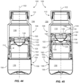
- FIGS. 4 , 6 , 44 and 46 illustrate examples of the system 100 with the shuttle element 108 depicted in the seal position.
- FIGS. 5 , 7 , 45 and 47 illustrate examples of the system 100 with the shuttle element 108 depicted out of the seal position.
- the beverage bottle system 100 may be configured such that (a) rotation of the first housing element 104 toward the storage position actuates the shuttle element 108 toward the seal position; (b) rotation of the first housing element 104 toward the mix position actuates the shuttle element 108 away from the seal position; (c) the first and second fluid compartments are sealed from fluid communication with one another when the shuttle element 108 is in the seal position; and (d) the first and second fluid compartments are in fluid communication with one another when the shuttle element 108 is not in the seal position.
- the first housing element 104 may include a shuttle transport portion 162;
- the shuttle element 108 may include a transport sleeve 164 in threaded engagement with the shuttle transport portion 162; and
- the actuations of the shuttle element 108 may be configured to be by way of the threaded engagement.
- the threaded engagement may be between transport threading 196 on the shuttle transport portion 162 and shuttle threading 198 in the shuttle element 108.
- the first housing element 104 may include a valve seat 120 with a valve aperture 126 extending therethrough.
- the valve aperture 126 may be configured to be in fluid communication between the first and second fluid compartments (116 and 118).
- the shuttle element 108 may include a valve plug 128 configured to sealingly engage the valve aperture 126 when the shuttle element 108 is in its seal position.
- the valve plug 128 may be conical, semispherical, or the like.
- the shuttle element 108 may include plurality of flow apertures 130 radially disposed about the valve plug 128.
- the flow apertures 130 may be configured to provide fluid communication pathways 178 between the first fluid compartment 116 and second fluid compartment 118 when the beverage bottle system 100 in its mix configuration.
- the valve seat 120 may include an annular seat flange 132 extending axially outward of the valve aperture 126 and may terminate at a flange lip 134.
- the shuttle element 108 may include a plug retention portion 136 on which the valve plug 128 is mounted
- the plug retention portion 136 may include an annular lip groove 138 extending circumferentially about the valve plug 128. Referring to FIGS. 4 and 44 , the lip groove 138 may be configured to be in sealing receipt of the flange lip 134 when the shuttle element 108 is in the seal position.
- the shuttle element 108 and the second housing element 106 may be (a) axially-slidable with respect to one another along the main axis and (b) non-rotatable with respect to one another about the main axis 102. Referring to FIGS. 15 , 20 , 58 , 63 , 77 and 85 this axially-slidability and non-rotatability may be by way of mutual engagement between respective linear splines 140 and linear grooves 142.
- the second housing element 106 may include a sidewall portion 144 having a sidewall inner surface 146.
- the linear splines 140 may be distributed about the transport sleeve 164 and the linear grooves 142 may be distributed about the sidewall inner surface 146.
- the linear grooves 142 are configured in shape and numerosity to further facilitate axial receipt of the shuttle element 104 by the second housing element 106 during initial assembly of the bottle system 100.
- the linear grooves 142 are evenly distributed circumferentially about the inner surface 146 of the sidewall portion 144, and feature tapered groove inlets toward the proximal end 180 of the second housing element 106.
- the linear splines 140 of the shuttle element 108 can be received any of the numerous linear grooves 142 of the second housing element 106 during assembly of the bottle system 100.
- the second housing element 106 can be axially slid into engagement with the shuttle element 108 and first housing element 104 during the bottle assembly process with little or no regard to the initial rotational orientation of the second housing element 106 about the main axis 102 with respect to the shuttle element 108.
- a beverage bottle system 100 may further comprise an inboard annular seal 122.
- the transport sleeve 164 may include a sleeve inner surface 148, and the inboard annular seal 122 may be disposed in fluid-sealing engagement between the shuttle transport portion 162 and the sleeve inner surface 148.
- the inboard annular seal 122 may preferably be mounted within an inboard seal groove 188 of the shuttle transport portion 162.
- FIGS. 45 and 54 the inboard annular seal 122 may preferably be mounted within an inboard seal groove 188 of the shuttle transport portion 162.
- the inboard annular seal 122 may be integrally affixed to the shuttle transport portion 162 during formation by way of, for example, bi-injection molding process mutually involving the inboard annual seal 122 and first housing element 104.
- the inboard annular seal may preferably be a thermoplastic elastomer (TPE) and the shuttle transport portion 162 may be a rigid plastic such as a polypropylene (PP).
- a beverage bottle system 100 may further comprise an outboard annular seal 124.
- the second housing element 106 may include a sidewall portion 144 having a sidewall inner surface 146, and the outboard annular seal 124 may be disposed in fluid-sealing engagement between the shuttle element 108 and the sidewall inner surface 146.
- the outboard annular seal 124 may be mounted within an outboard seal groove 190 in the shuttle element 108.
- the shuttle element 108 may include a shuttle seal flange 166, and the outboard annual seal 124 may be retained on the shuttle element 108 (and within outboard seal groove 190) by way of the shuttle seal flange 166.
- the shuttle element 108 may include a plurality of flange securement bosses 172 configured to extend through corresponding apertures in the shuttle seal flange 166 to facilitate fixed securement of the shuttle seal flange 166 to the remainder of the shuttle element 108.
- the ends of the flange securement bosses 172 may be heat-staked to secure the shuttle seal flange 166 in place on the remainder of the shuttle element 108.
- the outboard annular seal 124 may be integrally affixed to the shuttle element 108 during formation by way of, for example, bi-injection molding process mutually involving the outboard annual seal 124 and shuttle element 108.
- the outboard annular seal may preferably be a thermoplastic elastomer (TPE) and the shuttle element 108 may be a rigid plastic such as a polypropylene (PP).
- the second housing element 106 may include a closure securement portion 150 and a dispense aperture 152.
- the dispense aperture 152 may be configured to be in fluid communication between the second fluid compartment 118 and the ambient environment 154.
- the closure element 110 may be configured to (i) engage the closure securement portion 150 to seal the dispense aperture 152 from fluid communication with the ambient environment 154, and (ii) disengage the closure securement portion 150 to expose the dispense aperture 152 to fluid communication with the ambient environment 154.
- such engagement and disengagement of the closure element 110 may preferably by way of mutually-engageable threading on the closure securement portion 150 and the closure element 110.
- the closure element 110 may be comprised of a mutually-engageable over cap 204 and an inner cap 206
- the first housing element 104 may include a pair of first rotation detents 192
- the second housing element 106 may include a pair of second rotation detents 194.
- the first rotation detents 192 may be configured to be engageable with the second rotation detents 194 so as to limit the rotatability between the first housing element 104 and the second housing element 106.
- mutual rotatability may preferably be limited to 180 angular degrees or less.
- the shuttle element 108 may include a pair of detent reliefs 200 and corresponding relief terminal faces 202.
- the detent reliefs 200 may be configured to avoid interference between the first rotation detents 192 and the shuttle element 108 when the shuttle element 108 is being moved into and out of its seal position.
- the relief terminal faces 202 may be configured to be engaged by respective first rotation detents 192 once the shuttle element 108 reaches its seal position.
- the first housing element 104 includes a base portion 156 with a circumferentially uneven gripping surface 158 (e.g., knurled, indented, facetted, etc.).
- an intermediate mixing compartment 160 may be formed between the first fluid compartment 116 and the second fluid compartment 118 when the shuttle element 108 is not in its seal position (e.g., when the system 100 is in its mix configuration as shown in FIGS. 5 and 45 ).
- the first fluid chamber 116 contains a first beverage fluid
- the second fluid compartment 118 contains a second beverage fluid different from the first beverage fluid
- the shuttle element 108 is in the seal position.
- one of the beverage fluids may be alcoholic and the other beverage fluid non-alcoholic.
- the first fluid compartment 116 may have a first compartment pressure
- the second fluid compartment 118 may have a second compartment pressure different from the first compartment pressure (e.g., at least 20 PSI different than the first compartment pressure).
- the first housing element 104 may include an interface securement groove 186 disposed circumferentially thereabout.
- the second housing element 106 may have a proximal end 180, a distal end 182 and an interface securement lip 184. Referring to FIGS.
- the interface securement lip 184 may extend circumferentially about the proximal end 180 and be flexibly attached thereto (e.g., via a living hinge) for facilitating hinged movement of the interface securement lip 184 to a radially-inward position with respect to the second housing element 106 (e.g., with respect to the sidewall portion 144).
- the first housing element 104 and second housing element 106 may be axially secured to one another by way of engagement between the radially-inwardly positioned interface securement lip 184 and the interface securement groove 186.
- the base portion 156 and the shuttle transport portion 162 of the first housing element 104 may initially be formed independently of one another.
- the first housing element 104 may include a first attachment portion 168 (see, e.g., FIG. 49 ), and the shuttle transport portion 162 may include a second attachment portion 170 (see, e.g., FIG. 54 ).
- the separately-formed base portion 156 and shuttle transport portion 162 may be affixed to one another by way of, for example, ultrasonic weld or adhesion process between the first and second attachment portions.
- a radially-outer segment 162a and radially-inner segment 162b of the shuttle transport portion 162 may be integrally joined during formation of the first housing element 104 by way of, for example, co-molding process mutually involving the radially-outer segment 162a and the remainder of the first housing element 104.
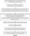
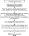
- FIGS. 67-69 and respectively corresponding FIGS. 70-72 , illustrate three different examples of a multi-compartment beverage bottle system fill, HPP and assembly process, of which the first assembly process, shown in Fig. 67 and 70 , is a method for manufacturing a multi-compartment beverage bottle according to the invention.
- the first assembly process shown in Fig. 67 and 70 , is a method for manufacturing a multi-compartment beverage bottle according to the invention.
- a first-stage subassembly is represented at 208
- a second-stage subassembly is represented at 210
- a third stage subassembly is represented at 212
- a first fluid is represented at 214
- a second fluid is represented at 216
- an ambient environment is represented at 154
- a high-pressure processing (HPP) chamber is represented at 218
- a drying element is represented at 220.
- the HPP chamber 218 contains a hydraulic fluid (e.g., water) within which the respective subassemblies remain submerged during HPP pressurization. Drying refers to the removal of the hydraulic fluid from the outer surfaces of the respective subassemblies following completion of the HPP.
- a hydraulic fluid e.g., water
- Alcohol is a term used throughout the specification and/or claims and is accordingly defined as a liquid, synthesized or obtained by fermentation of sugars and starches and widely used, either pure or denatured, as a solvent and in drugs, cleaning solutions, explosives, and intoxicating beverages.
- “Beverage” is a term used throughout the specification and/or claims and is accordingly defined as any of various liquids for drinking.
- Component is a term used throughout the specification and/or claims and is accordingly defined as a constituent element, as of a system.
- Fasten is a term used throughout the specification and/or claims and is accordingly defined as a means making an object difficult to remove, including heat sealing, adhesive, or various irreversible locking mechanisms.
- Fluid is a term used throughout the specification and/or claims and is accordingly defined as a continuous, amorphous substance whose molecules move freely past one another and that has the tendency to assume the shape of its container; a liquid or gas.
- High Pressure Processing is a term used throughout the specification and/or claims and is accordingly defined as a method of preserving and sterilizing food, in which a product is processed under very high pressure, leading to the inactivation of certain microorganisms and enzymes in the food.
- HPP is a method of food processing where food is subjected to elevated pressures (up to approximately 600000 kPA or 87,000 pounds per square inch or approximately 6,000 atmospheres), with or without the addition of heat, to achieve microbial inactivation or to alter the food attributes in order to achieve consumer-desired qualities. Pressure inactivates most vegetative bacteria at pressures above 413685 kPa (60,000 pounds per square inch). HPP retains food quality, maintains natural freshness, and extends microbiological shelf life.
- HPP high hydrostatic pressure processing
- UHP ultra-high-pressure processing
- HPP results in foods with fresher taste, and better appearance, texture and nutrition.
- High pressure processing can be conducted at ambient or refrigerated temperatures, thereby eliminating thermally induced cooked off-flavors.
- the technology is especially beneficial for heat-sensitive products.
- Most processed foods today are heat treated to kill bacteria, which often diminishes product quality.
- High pressure processing provides an alternative means of killing bacteria that can cause spoilage or food-borne disease without a loss of sensory quality or nutrients.
- the product is packaged in a flexible container (usually a pouch or plastic bottle) and is loaded into a high pressure chamber filled with a pressure transmitting (hydraulic) fluid.
- the hydraulic fluid (normally water) in the chamber is pressurized with a pump, and this pressure is transmitted through the package into the food itself. Pressure is applied for a specific time, usually 3 to 5 minutes.
- the processed product is then removed and stored/distributed in the conventional manner. Because the pressure is transmitted uniformly (in all directions simultaneously), food retains its shape, even at extreme pressures. And because no heat is needed, the sensory characteristics of the food are retained without compromising microbial safety.
- the HPP process is widely used in a variety of food manufacturing contexts, including meat packing, distribution of hummus, salsas, and guacamoles, juices, soups, and other applications.
- Solution is a term used throughout the specification and/or claims and is accordingly defined as a homogeneous, molecular mixture of two or more substances.
- Subject is a term used throughout the specification and/or claims and is accordingly defined as a species of matter of definite chemical composition.
- the method in accordance with the present invention generally involves manufacturing a multi-compartment beverage container that discretely stores beverage ingredients, such ingredients usually being distinct, in separate chambers.
- beverage ingredients such ingredients usually being distinct, in separate chambers.
- the consumer twists the container appropriately to cause communication between the separated compartments to allow the ingredients to mix, thereby creating a final beverage product ready for dispensing and consumption.
- a unique method of making the container, filling it with the appropriate ingredients, is disclosed.
- Examples of a system may contain perishable juice or other liquids in a first compartment or chamber and an alcohol or spirit in a second compartment or chamber initially separated from the first compartment at the time of filling.
- the purpose of separating these beverage components or ingredients from one another is to prevent the first liquid (for example, raw juice) from being adulterated from the other substance before a consumer drinks the beverage.
- Such adulteration of the non-alcoholic beverage component may be caused by pasteurization or the addition of preservatives. Therefore, examples of the system initially compartmentalize the ingredients, typically separating alcoholic substances from non-alcoholic substances such as juice or flavoring so that the alcohol does not degrade the quality and nutrition offered by the non-alcoholic juice or flavoring.
- Characteristics of the nonalcoholic beverage requiring proper protection may include flavor, color, viscosity, chemical structure, smell, freshness, and nutrition. Accordingly, mixing the components at the time of imbibing allows for the highest quality and freshness since the elapsed time of the ingredients being mixed is minimized, thereby reducing the potential for a chemical breakdown among the ingredients which would negatively affect their desired individual characteristics.
- Examples in one or other compartments may withstand incredibly high amounts of pressure under HPP (while submerged under water or otherwise, which occurs during the HPP process).
- an internal valve may separate the two internal chambers and be designed to withstand HPP, by way of not allowing the two separated substances to interact before the system/container is activated thereby enabling the two substances to interact.
- the system may be used as a means to distribute two distinct substances in separate compartments within the same container, of which the first compartment at some point would be subjected to HPP, ensuring such substances remain unadulterated during the manufacturing, distributing, and merchandising processes.
- the system may also be used as a means of convenience for an end user to mix multiple substances within one container without the need to purchase or obtain such substances separately.
- a method of use includes the twisting of the bottle to mix the contents of each chamber to formulate the final beverage for consumer consumption. This process can also include the opening or unsealing of the container and the dispensing of the product.
- one or more components of the system 100 of the present disclosure may be constructed of a clear or transparent or translucent material in order to better identify/view the liquids contained within the upper chamber and/or lower chamber. Any number of colored dyes may be used to color the external or internal pieces.
- first fluid compartment 116 can have less volume than the second fluid compartment 118, different ratios of liquids in each respective compartment may be used.
- the components of the presently-disclosed examples may be injection molded with a variety of different plastic resins, such as polyethylene terephthalate (pet) plastic or clarified polypropylene plastic. Any number of colored dyes may be used to color the external or internal components.
- the first and second housing elements of examples of a beverage bottle system may be constructed of a clear or transparent or translucent material in order to better identify/view the liquids contained within the first chamber and the second chamber.
- the second fluid compartment 118 one may be able to see, for example, a colored liquid or juice, whether it be orange, purple, red, etc, while also seeing a clear, and potentially tinted yellow or orange, liquid in the first fluid compartment 116.
- There can be little branding and labeling on the bottle so as to accentuate the contrast between the two compartments.
- the separation of the compartments may preferably be relatively in the middle of the package so that they will look equal in quantity.
- valve subsystem may also be in clear, translucent plastic, thereby causing the inner mechanics of the system/container to appear to be invisible when immersed in clear liquid in the bottom chamber, as well as making the liquid in the uppermost compartment appear to be floating without any support.
- Bottle or dispensing caps may be blow molded. There may be one or more pieces that use alternative molding processes, such as blow molding or injection blow molding for more flexible and less rigid walls purposes of novel manufacturing, distribution or merchandising processes, including food processing application such as pasteurization or HPP.
- the closure element 110 e.g., cap
- the closure element 110 may be a stock cap that can be provided by BERICAP TM or another manufacturer of closures.
- the first fluid compartment 116 is filled, sealed, and HPP'd independently of the second fluid compartment 118.
- HPP may be used in conjunction with rigid plastics used in the construction of the beverage bottle. If sufficiently rigid plastics are used, HPP may provide no expansion of the beverage bottle body or no expansion of the contents of the beverage bottle.
- HPP flexible plastics, thinner, less rigid construction may allow the plastic to expand (e.g., approximately 15%) as necessary to allow the pressure to adequately pass through the walls of the container to compress the juice.
- the second fluid compartment may have a different pressure allowance than the first fluid compartment.
- the consumer may watch the two liquids combine and one or both liquids change color upon mixing throughout pieces.
- the user opens or removes the closure element 110, to pour the mixed beverage through the dispensing aperture 152.
- the bottles may be constructed to resemble any commercially available bottle for holding a liquid beverage and may be manufactured from any suitable plastic, glass or metal material.
- the bottles may be adapted to store any suitable liquid, such as, for example, water, juice, milk, carbonated sodas, protein shakes, energy drinks, flavored water, beer, wine, and liquor, and not limited to only beverages or juices or alcohol. Additional manufacturing and/or bottling process steps may be incorporated, such as treating the bottle parts or bottle assembly to prevent the spread of pathogens.
- the antimicrobial materials may be added to the plastic used to form the parts so that they resist growth of bacteria or viruses.
- the parts or bottle assembly may be sprayed prior to bottle shipment to sanitize the bottles via such an antibacterial treatment.
- all the pieces of the present example are not limited to its current bottle design or shape, but can include other modified forms which yet still achieve the same internal functionality and utility.
- the cylindrical shape provides users a readily understood context in that the example is used as a beverage container. This shape also provides for ease of packing and distribution, grip for a user, and assembly line filling and capping.
Landscapes
- Engineering & Computer Science (AREA)
- Mechanical Engineering (AREA)
- Chemical & Material Sciences (AREA)
- Organic Chemistry (AREA)
- Health & Medical Sciences (AREA)
- Life Sciences & Earth Sciences (AREA)
- Wood Science & Technology (AREA)
- Nutrition Science (AREA)
- General Engineering & Computer Science (AREA)
- General Health & Medical Sciences (AREA)
- Genetics & Genomics (AREA)
- Biochemistry (AREA)
- Manufacturing & Machinery (AREA)
- Zoology (AREA)
- Ceramic Engineering (AREA)
- Bioinformatics & Cheminformatics (AREA)
- Food Science & Technology (AREA)
- Polymers & Plastics (AREA)
- Closures For Containers (AREA)
- Packages (AREA)
- Package Specialized In Special Use (AREA)
- Thermally Insulated Containers For Foods (AREA)
- Packging For Living Organisms, Food Or Medicinal Products That Are Sensitive To Environmental Conditiond (AREA)
- Filling Of Jars Or Cans And Processes For Cleaning And Sealing Jars (AREA)
- Details Of Rigid Or Semi-Rigid Containers (AREA)
Description
- This application claims the benefit of
U.S. Provisional Application No. 62/679,578 filed June 1, 2018 U.S. Provisional Application No. 62/770,657 filed November 21, 2018 - The present disclosure relates generally to a method for manufacturing a multi-compartment beverage container configured to store and transport one or more beverage ingredients.
- An enormous market for consumer beverage products exists for both alcoholic and non-alcoholic beverages and more recently many alcoholic cocktail drinks or alcoholic mixed beverages are being sold in premixed form, including margaritas, daiquiris, etc.
- Ready-to-drink cocktails currently sold in grocery stores typically contain an alcohol in the form of beer, malt liquor or distilled spirits premixed with a pasteurized juice or flavor mix, which includes additional natural and artificial preservatives, colorants, and stabilizers. This standard formulation available to consumers has many disadvantages that can be solved using innovative container technology.
- Liquid storage containers have been provided in numerous shapes and sizes for various liquid commodities. Today's most common liquid storage containers are plastic and provide multiple shapes and sizes with mass production capability and recyclable materials. A popular liquid storage container designed for beverage consumption is a drinking bottle, often formed of a molded plastic material. Such beverage bottles may include a removable closure or cap fastened or sealed to a complementary neck at the upper end of the bottle. The bottle body defines an interior chamber communicating with the neck, which is designed to transport and store the consumable beverage.
- Materials used to manufacture beverage containers include glass, aluminum, plastic, paperboard or cardboard, and tin. Alcoholic beverage containers are often made from aluminum or glass while non-alcoholic beverage containers or drink mixes are often made from plastic or paperboard. Instead of purchasing alcohol solely from bars and restaurants by the glass, alcoholic beverages are available for consumer purchase in off-site retail locations. Such alcoholic beverages packaged for retail sale include beer, wine, distilled spirits, and blends with nonalcoholic liquids. Finally, consumer trends continue to advance toward healthier beverages or foodstuffs that are created from natural and organic ingredients rather than processed foods or those with preservatives. This trend is beginning to be reflected with alcohol beverages, as exemplified by an increasing amount of low-calorie, gluten-free, and organic options.
- Juices and other liquids are commonly sold in retail locations. In the last decade, a variety of raw juice products, which are not pasteurized or possess preservatives of any kind, whether natural or not, nor additional colorants or flavor enhancers, are becoming increasingly popular. Their popularity is predicated upon improved taste and health benefits, as compared to traditional pasteurized products, as well as their convenience, compared to juicing a whole fruit or vegetable with a juicing machine or by hand. Some companies are also developing raw juice brands that are to be used as mixers for alcoholic beverages. A consumer purchases the raw juice and alcohol separately, combining the two liquids when ready for consumption.
- Generally, there are two classes of raw beverages, whether they be juice, coffee, tea, soups or other food stuffs: ones that are widely distributed with a shelf life over a month, and those which are not distributed and possess a shelf life of a few days. In order to increase the shelf life of a product without pasteurizing it and enabling a company to widely distribute a raw product, it must undergo high pressure processing ("HPP"). In order to increase the shelf life of the raw juice (for example, from two days to two months refrigerated), it will undergo HPP, which typically place 551580 kPa (80,000 pounds of pressure per square inch) submersed in water in a high-pressure chamber.
- In the beverage industry generally, a number of products include a dispensing cap or secondary chamber on top of a plastic bottle used for beverages. Such dispensing caps are used to separate a secondary liquid from the primary liquid below in order to preserve the liquid in the secondary chamber or to create a unique experience, whether the liquid is a flavor enhancer, vitamin, probiotic or other nutraceutical, alcoholic, or any other liquid. By keeping the two liquids separated until consumption, each liquid is not diluted or negatively affected if mixed for days, months, or even years. From
WO2011151834 a multi-compartment beverage bottle and method for its manufacturing according to the preamble of appended claim 1 is known, whereby the first housing of the bottle contains a first fluid, the first housing being sealed by a shuttle element, the bottle further comprising a second housing containing a second fluid. - This invention, defined in the appended claim, provides a method of manufacturing multi-chamber beverage bottles designed to preserve the freshness of individual ingredients bottled in each chamber while also allowing a consumer or server to easily mix the ingredients at the point of consumption using a simple twisting motion as part of a fun and satisfying way to open the beverage container.
- Advantages of the present method may become apparent to those skilled in the art with the benefit of the following detailed description of the examples and upon reference to the accompanying drawings in which:
-
FIG. 1 is a diagrammatic perspective view of one example multi-compartment beverage bottle system not forming part of the invention; -
FIG. 2 is a diagrammatic side view of the example beverage bottle system ofFIG. 1 ; -
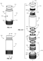
FIG. 3 is a diagrammatic exploded view of the example beverage bottle system ofFIG. 1 ; -
FIG. 4 is a diagrammatic cross-sectional view taken along lines 4-4 inFIG. 2 , showing the beverage bottle system in a seal configuration wherein the first housing element is in a storage position and the shuttle element in a seal position; -
FIG. 5 is a further diagrammatic cross-sectional view taken along lines 4-4 inFIG. 2 , but showing the beverage bottle system in a mix configuration wherein the first housing element is in a mix position and the shuttle element is out of its seal position; -
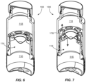
FIG. 6 is a diagrammatic perspective cut away view wherein the cut is taken along lines 4-4 inFIG. 2 , and showing the beverage bottle system in a seal configuration wherein the first housing element is in a storage position and the shuttle element in a seal position; -
FIG. 7 is a diagrammatic perspective cut away view wherein the cut is taken along lines 4-4 inFIG. 2 , and showing the beverage bottle system in a mix configuration wherein the first housing element is in a mix position and the shuttle element is out of its seal position; -
FIG. 8 is a diagrammatic perspective view of an example first housing element in accordance with the example beverage bottle system ofFIG. 1 ; -
FIG. 9 is a further diagrammatic perspective view of the first housing element shown inFIG. 8 ; -
FIG. 10 is a diagrammatic side view of the first housing element shown inFIG. 8 ; -
FIG. 11 is a diagrammatic cross-sectional view taken along lines 11-11 inFIG. 10 ; -
FIG. 12 is a diagrammatic side view similar to that ofFIG. 10 , but wherein the first housing element is at least semitransparent; -
FIG. 13 is a diagrammatic perspective view of the first housing element ofFIG. 12 ; -
FIG. 14 is a diagrammatic side view of an example second housing element in accordance with the example beverage bottle system ofFIG. 1 ; -
FIG. 15 is a diagrammatic cross-sectional view taken along lines 15-15 inFIG. 14 ; -
FIG. 16 is a diagrammatic perceptive view of a second housing element similar to that shown inFIG. 14 , but wherein the second housing element is at least semitransparent; -
FIG. 17 is a diagrammatic perspective view of the second housing element ofFIG. 14 ; -
FIG. 18 is a diagrammatic perspective view of a shuttle element in accordance with the example beverage bottle system ofFIG. 1 ; -
FIG. 19 is a further diagrammatic perspective view of the shuttle element ofFIG. 18 ; -
FIG. 20 is a diagrammatic side view of the shuttle element ofFIG. 18 ; -
FIG. 21 is a diagrammatic cross-sectional view taken along lines 21-21 inFIG. 20 ; -
FIG. 22 is a diagrammatic top view of the shuttle element ofFIG. 18 ; -
FIG. 23 is a diagrammatic bottom view of the shuttle element ofFIG. 18 ; -
FIG. 24 is a further diagrammatic perspective view of the shuttle element ofFIG. 18 , but wherein the shuttle element is at least semitransparent; -
FIG. 25 is a diagrammatic perspective view of a valve seat in accordance with the example beverage bottle system ofFIG. 1 ; -
FIG. 26 is a further diagrammatic perspective view of the valve seat ofFIG. 25 ; -
FIG. 27 is a diagrammatic side view of the valve seat ofFIG. 25 ; -
FIG. 28 is a diagrammatic cross-sectional view taken along lines 28-28 inFIG. 27 ; -
FIG. 29 is a diagrammatic top view of the valve seat ofFIG. 25 ; -
FIG. 30 is a diagrammatic perspective view of an outboard annular seal in accordance with the example beverage bottle system ofFIG. 1 ; -
FIG. 31 is a diagrammatic partial cross-sectional view of the outboard annular seal ofFIG. 30 ; -
FIG. 32 is a diagrammatic side view of an example inner cap; -
FIG. 33 is a diagrammatic cross-sectional view taken along lines 33-33 inFIG. 32 ; -
FIG. 34 is a diagrammatic perspective view of the inner cap ofFIG. 32 ; -
FIG. 35 is a diagrammatic side view of an example over cap; -
FIG. 36 is a diagrammatic cross-sectional view taken along lines 36-36 inFIG. 35 ; -
FIG. 37 is a diagrammatic perspective view of the over cap ofFIG. 35 ; -
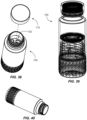
FIG. 38 is a diagrammatic perspective view of the example beverage bottle system ofFIG. 1 , but with the closure element disengaged from the closure securement portion so as to expose the dispense aperture to fluid communication with the ambient environment; -
FIG. 39 is a diagrammatic perspective view of the example beverage bottle system ofFIG. 1 , but with the system components being shown in at least semitransparent form; -
FIG. 40 is a diagrammatic perspective view of the example beverage bottle system ofFIG. 1 , but with the closure element removed and the system being in a fluid pouring orientation; -
FIG. 41 is a diagrammatic perspective view of a second example multi-compartment beverage bottle system not forming part of the invention; -
FIG. 42 is a diagrammatic side view of the example beverage bottle system ofFIG. 41 ; -
FIG. 43 is a diagrammatic exploded view of the example beverage bottle system ofFIG. 41 ; -
FIG. 44 is a diagrammatic cross-sectional view taken along lines 44-44 inFIG. 42 , showing the beverage bottle system in a seal configuration wherein the first housing element is in a storage position and the shuttle element in a seal position; -
FIG. 45 is a further diagrammatic cross-sectional view taken along lines 44-44 inFIG. 42 , but showing the beverage bottle system in a mix configuration wherein the first housing element is in a mix position and the shuttle element is out of its seal position; -
FIG. 46 is a diagrammatic perspective cut away view wherein the cut is taken along lines 44-44 inFIG. 42 , and showing the beverage bottle system in a seal configuration wherein the first housing element is in a storage position and the shuttle element in a seal position; -
FIG. 47 is a diagrammatic perspective cut away view wherein the cut is taken along lines 44-44 inFIG. 42 , and showing the beverage bottle system in a mix configuration wherein the first housing element is in a mix position and the shuttle element is out of its seal position; -
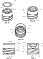
FIG. 48 is a diagrammatic perspective view of a base portion of the example beverage bottle system ofFIG. 41 ; -
FIG. 49 is a further diagrammatic perspective view of the base portion ofFIG. 48 ; -
FIG. 50 is a diagrammatic side view of the base portion ofFIG. 48 ; -
FIG. 51 is a diagrammatic cross-sectional view taken along lines 51-51 inFIG. 50 ; -
FIG. 52 is a diagrammatic perspective view of a shuttle transport portion of the example beverage bottle system ofFIG. 41 ; -
FIG. 53 is a further diagrammatic perspective view of the shuttle transport portion ofFIG. 52 ; -
FIG. 54 is a diagrammatic side view of the base portion ofFIG. 52 ; -
FIG. 55 is a diagrammatic cross-sectional view taken along lines 55-55 inFIG. 54 ; -
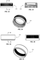
FIG. 56 is a diagrammatic perspective view of a shuttle seal flange of the beverage bottle system ofFIG. 41 ; -
FIG. 57 is a diagrammatic exploded view of a shuttle element of the beverage bottle system ofFIG. 41 , wherein the shuttle seal flange is shown prior to being secured to the remainder of the shuttle element; -
FIG. 58 is a diagrammatic perspective view of a shuttle element similar to that shown inFIG. 41 , but wherein the shuttle seal flange is shown secured to the reminder of the shuttle element; -
FIG. 59 is a further diagrammatic perspective view of the shuttle element ofFIG. 58 ; -
FIG. 60 is a diagrammatic side view of the base portion ofFIG. 58 ; -
FIG. 61 is a diagrammatic cross-sectional view taken along lines 61-61 inFIG. 60 ; -
FIG. 62 is a diagrammatic side view of an example second housing element in accordance with the example beverage bottle system ofFIG. 41 ; -
FIG. 63 is a diagrammatic cross-sectional view taken along lines 63-63 inFIG. 62 ; -
FIG. 64 is a diagrammatic perspective view of the second housing element ofFIG. 62 ; -
FIG. 65 is a diagrammatic perceptive view of a second housing element similar to that shown inFIG. 62 , but wherein the second housing element is at least semitransparent; -
FIG. 66 is a diagrammatic partial cross-sectional view of one example outboard annular seal; -
FIG. 67 is a diagrammatic flow chart illustrating a multi-compartment beverage bottle system fill, HPP and assembly process according to the invention; -
FIG. 68 is a diagrammatic flow chart illustrating a second example of a multi-compartment beverage bottle system fill, HPP and assembly process, not forming part of the invention; -
FIG. 69 is a diagrammatic flow chart illustrating a third example of a multi-compartment beverage bottle system fill, HPP and assembly process, not forming part of the invention; -
FIG. 70 is a diagrammatic chart illustrating the inventive process in accordance withFIG. 67 as applied to one of the examples of a bottle system illustrated herein; -
FIG. 71 is a diagrammatic chart illustrating the process in accordance withFIG. 68 , not forming part of the invention, as applied to one of the examples of a bottle system illustrated herein; -
FIG. 72 is a diagrammatic chart illustrating the process in accordance withFIG. 69 , not forming part of the invention, as applied to one of the examples of a bottle system illustrated herein; -
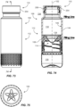
FIG. 73 is a diagrammatic side view of a third example multi-compartment beverage bottle system not forming part of the invention; -
FIG. 74 is a diagrammatic cross-sectional view taken along lines 74-74 inFIG. 73 , showing the beverage bottle system in a seal configuration wherein the first housing element is in a storage position and the shuttle element in a seal position -
FIG. 75 is a diagrammatic bottom view of the bottle ofFIG. 73 ; -
FIG. 76 is a diagrammatic exploded view of the example beverage bottle system ofFIG. 73 ; -
FIG. 77 is a diagrammatic side view of an example second housing element in accordance with the example beverage bottle system ofFIG. 1 ; -
FIG. 78 is a diagrammatic perspective view of an example first housing element in accordance with the example beverage bottle system ofFIG. 73 ; -
FIG. 79 is a diagrammatic side view of an example second housing element in accordance with the example beverage bottle system ofFIG. 73 ; -
FIG. 80 is a diagrammatic cross-sectional view taken along lines 80-80 inFIG. 79 ; -
FIG. 81 is a diagrammatic top view of the second housing element ofFIG. 79 ; -
FIG. 82 is a diagrammatic bottom view of the second housing element ofFIG. 79 ; -
FIG. 83 is a diagrammatic cross-sectional view taken along lines 83-83 inFIG. 80 ; -
FIG. 84 is a magnified view ofdetail 84 ofFIG. 80 ; -
FIG. 85 is a diagrammatic perspective view of a shuttle element in accordance with the example beverage bottle system ofFIG. 73 ; -
FIG. 86 is a diagrammatic top view of the shuttle element ofFIG. 85 ; -
FIG. 87 is a diagrammatic side view of the shuttle element ofFIG. 85 ; -
FIG. 88 is a further diagrammatic side view of the shuttle element ofFIG. 85 , taken at a 90-degree angle with respect toFIG. 87 ; -
FIG. 89 is a diagrammatic cross-sectional view taken along lines 89-89 inFIG. 87 ; -
FIG. 90 is a diagrammatic cross-sectional view taken along lines 90-90 inFIG. 88 ; -
FIG. 91 is a diagrammatic bottom view of the shuttle element ofFIG. 85 ; -
FIG. 92 is a magnified view ofdetail 92 ofFIG. 89 , illustrating the outboard annular seal having been formed in affixed engagement with the shuttle element by way of a bi-injection molding process; -
FIG. 93 is a magnified view ofdetail 93 ofFIG. 89 ; -
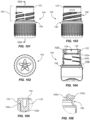
FIG. 94 is a diagrammatic side view of a radially-outer segment of a shuttle transport portion in accordance with the bottle system ofFIG. 73 ; -
FIG. 95 is a diagrammatic bottom view of the radially-outer segment ofFIG. 94 ; -
FIG. 96 is a diagrammatic cross-sectional view taken along lines 96-96 inFIG. 94 ; -
FIG. 97 is a further diagrammatic side view of the radially-outer segment ofFIG. 94 , taken at a 90-degree angle with respect toFIG. 94 ; -
FIG. 98 is a diagrammatic perspective view of the radially-outer segment ofFIG. 94 ; -
FIG. 99 is a magnified view ofdetail 99 ofFIG. 94 ; -
FIG. 100 is a magnified view ofdetail 100 ofFIG. 96 ; -
FIG. 101 is a diagrammatic side view of a first housing element of a shuttle transport portion in accordance with the bottle system ofFIG. 73 ; -
FIG. 102 is a diagrammatic bottom view of the first housing element ofFIG. 101 ; -
FIG. 103 is a further diagrammatic side view of the first housing element ofFIG. 101 , taken at a 90-degree angle with respect toFIG. 101 ; -
FIG. 104 is a diagrammatic cross-sectional view taken along lines 104-104 inFIG. 101 , illustrating the radially-outer segment of the shuttle transport portion having been co-molded with the remainder of the first housing element; -
FIG. 105 is a magnified view ofdetail 105 ofFIG. 104 , illustrating the inboard annular seal having been formed in affixed engagement with the first housing element by way of a bi-injection molding process; and -
FIG. 106 is a magnified view ofdetail 106 ofFIG. 104 . - Referring now to the drawings, like reference numerals designate identical or corresponding features throughout the several views.
- With reference to the several drawings, various examples of a multi-compartment beverage bottle system are shown at 100, and comprise a
first housing element 104, asecond housing element 106, ashuttle element 108 and aclosure element 110. - Referring to
FIGS 1-5 ,41-45 , and73-76 thefirst housing element 104 andsecond housing element 106 are in mutual engagement with one another to at least partially define afluid vessel 112 with afluid cavity 114 therein. Thefluid cavity 114 includes afirst fluid compartment 116 and asecond fluid compartment 118. Thefirst housing element 104 may be rotatable with respect to thesecond housing element 106 about amain axis 102 for rotation of thefirst housing element 104 between a storage position and a mix position. - The
shuttle element 108 is disposed within thefluid cavity 114 and axially actuatable along themain axis 102 into and out of a seal position.FIGS. 4 ,6 ,44 and46 illustrate examples of thesystem 100 with theshuttle element 108 depicted in the seal position. Contrastingly,FIGS. 5 ,7 ,45 and47 illustrate examples of thesystem 100 with theshuttle element 108 depicted out of the seal position. Thebeverage bottle system 100 may be configured such that (a) rotation of thefirst housing element 104 toward the storage position actuates theshuttle element 108 toward the seal position; (b) rotation of thefirst housing element 104 toward the mix position actuates theshuttle element 108 away from the seal position; (c) the first and second fluid compartments are sealed from fluid communication with one another when theshuttle element 108 is in the seal position; and (d) the first and second fluid compartments are in fluid communication with one another when theshuttle element 108 is not in the seal position. - In particular preferred examples of the multi-compartment
beverage bottle system 100, (a) thefirst housing element 104 may include ashuttle transport portion 162; (b) theshuttle element 108 may include atransport sleeve 164 in threaded engagement with theshuttle transport portion 162; and (c) the actuations of theshuttle element 108 may be configured to be by way of the threaded engagement. The threaded engagement may be between transport threading 196 on theshuttle transport portion 162 and shuttle threading 198 in theshuttle element 108. - Referring to
FIGS. 4, 5 ,44, 45 and74 in certain preferred examples of thesystem 100, thefirst housing element 104 may include avalve seat 120 with avalve aperture 126 extending therethrough. Thevalve aperture 126 may be configured to be in fluid communication between the first and second fluid compartments (116 and 118). Moreover, theshuttle element 108 may include avalve plug 128 configured to sealingly engage thevalve aperture 126 when theshuttle element 108 is in its seal position. Thevalve plug 128 may be conical, semispherical, or the like. - Referring to
FIGS. 22 and59 , theshuttle element 108 may include plurality offlow apertures 130 radially disposed about thevalve plug 128. Referring toFIGS. 7 and47 , theflow apertures 130 may be configured to providefluid communication pathways 178 between thefirst fluid compartment 116 andsecond fluid compartment 118 when thebeverage bottle system 100 in its mix configuration. - Referring to
FIGS. 5 and45 , in particular preferred examples of abeverage bottle system 100, thevalve seat 120 may include anannular seat flange 132 extending axially outward of thevalve aperture 126 and may terminate at aflange lip 134. Theshuttle element 108 may include aplug retention portion 136 on which thevalve plug 128 is mounted Theplug retention portion 136 may include anannular lip groove 138 extending circumferentially about thevalve plug 128. Referring toFIGS. 4 and44 , thelip groove 138 may be configured to be in sealing receipt of theflange lip 134 when theshuttle element 108 is in the seal position. - In certain examples of a
beverage bottle system 100, theshuttle element 108 and thesecond housing element 106 may be (a) axially-slidable with respect to one another along the main axis and (b) non-rotatable with respect to one another about themain axis 102. Referring toFIGS. 15 ,20 ,58 ,63 ,77 and85 this axially-slidability and non-rotatability may be by way of mutual engagement between respectivelinear splines 140 andlinear grooves 142. Moreover, thesecond housing element 106 may include asidewall portion 144 having a sidewallinner surface 146. Thelinear splines 140 may be distributed about thetransport sleeve 164 and thelinear grooves 142 may be distributed about the sidewallinner surface 146. - Notably, in the
bottle system 100 ofFIGS. 73-106 , thelinear grooves 142 are configured in shape and numerosity to further facilitate axial receipt of theshuttle element 104 by thesecond housing element 106 during initial assembly of thebottle system 100. By way of example, as illustrated inFIGS. 76, 77 ,80 and 84 , thelinear grooves 142 are evenly distributed circumferentially about theinner surface 146 of thesidewall portion 144, and feature tapered groove inlets toward theproximal end 180 of thesecond housing element 106. As a result of this construction, thelinear splines 140 of theshuttle element 108 can be received any of the numerouslinear grooves 142 of thesecond housing element 106 during assembly of thebottle system 100. Thus, thesecond housing element 106 can be axially slid into engagement with theshuttle element 108 andfirst housing element 104 during the bottle assembly process with little or no regard to the initial rotational orientation of thesecond housing element 106 about themain axis 102 with respect to theshuttle element 108. - Referring to
FIGS. 5 and45 , particular examples of abeverage bottle system 100 may further comprise an inboardannular seal 122. Thetransport sleeve 164 may include a sleeveinner surface 148, and the inboardannular seal 122 may be disposed in fluid-sealing engagement between theshuttle transport portion 162 and the sleeveinner surface 148. Referring toFIGS. 45 and54 , the inboardannular seal 122 may preferably be mounted within aninboard seal groove 188 of theshuttle transport portion 162. Alternatively, referring toFIGS. 104 and 105 for example, the inboardannular seal 122 may be integrally affixed to theshuttle transport portion 162 during formation by way of, for example, bi-injection molding process mutually involving the inboardannual seal 122 andfirst housing element 104. In such examples, the inboard annular seal may preferably be a thermoplastic elastomer (TPE) and theshuttle transport portion 162 may be a rigid plastic such as a polypropylene (PP). - Referring again to
FIGS. 5 and45 , certain examples of abeverage bottle system 100 may further comprise an outboardannular seal 124. Thesecond housing element 106 may include asidewall portion 144 having a sidewallinner surface 146, and the outboardannular seal 124 may be disposed in fluid-sealing engagement between theshuttle element 108 and the sidewallinner surface 146. Referring toFIGS. 45 and60 , the outboardannular seal 124 may be mounted within anoutboard seal groove 190 in theshuttle element 108. Moreover, referring toFIGS 45 and61 , in particular examples of thebeverage bottle system 100, theshuttle element 108 may include ashuttle seal flange 166, and the outboardannual seal 124 may be retained on the shuttle element 108 (and within outboard seal groove 190) by way of theshuttle seal flange 166. Referring toFIGS. 56-61 , theshuttle element 108 may include a plurality offlange securement bosses 172 configured to extend through corresponding apertures in theshuttle seal flange 166 to facilitate fixed securement of theshuttle seal flange 166 to the remainder of theshuttle element 108. For example, the ends of theflange securement bosses 172 may be heat-staked to secure theshuttle seal flange 166 in place on the remainder of theshuttle element 108. Alternatively, referring toFIGS. 89 and 92 for example, the outboardannular seal 124 may be integrally affixed to theshuttle element 108 during formation by way of, for example, bi-injection molding process mutually involving the outboardannual seal 124 andshuttle element 108. In such examples, the outboard annular seal may preferably be a thermoplastic elastomer (TPE) and theshuttle element 108 may be a rigid plastic such as a polypropylene (PP). - Referring to
FIGS. 3 and53 , thesecond housing element 106 may include aclosure securement portion 150 and a dispenseaperture 152. Referring toFIGS. 4 and44 , the dispenseaperture 152 may be configured to be in fluid communication between thesecond fluid compartment 118 and theambient environment 154. Theclosure element 110 may be configured to (i) engage theclosure securement portion 150 to seal the dispenseaperture 152 from fluid communication with theambient environment 154, and (ii) disengage theclosure securement portion 150 to expose the dispenseaperture 152 to fluid communication with theambient environment 154. Referring toFIGS. 14 and34 , such engagement and disengagement of theclosure element 110 may preferably by way of mutually-engageable threading on theclosure securement portion 150 and theclosure element 110. Referring toFIGS. 3 and43 , theclosure element 110 may be comprised of a mutually-engageable overcap 204 and aninner cap 206 - Referring to
FIGS. 9 ,16 ,49 and65 , in particular examples of abeverage bottle system 100, thefirst housing element 104 may include a pair offirst rotation detents 192, and thesecond housing element 106 may include a pair ofsecond rotation detents 194. Thefirst rotation detents 192 may be configured to be engageable with thesecond rotation detents 194 so as to limit the rotatability between thefirst housing element 104 and thesecond housing element 106. For example, such mutual rotatability may preferably be limited to 180 angular degrees or less. - Referring to
FIGS. 20 and61 , theshuttle element 108 may include a pair ofdetent reliefs 200 and corresponding relief terminal faces 202. The detent reliefs 200 may be configured to avoid interference between thefirst rotation detents 192 and theshuttle element 108 when theshuttle element 108 is being moved into and out of its seal position. The relief terminal faces 202 may be configured to be engaged by respectivefirst rotation detents 192 once theshuttle element 108 reaches its seal position. - Referring to
FIGS. 4 ,10 ,45 and50 , in certain preferred examples of abeverage bottle system 100, thefirst housing element 104 includes abase portion 156 with a circumferentially uneven gripping surface 158 (e.g., knurled, indented, facetted, etc.). - Referring to
FIGS. 5 and45 , in particular preferred examples of abeverage bottle system 100, anintermediate mixing compartment 160 may be formed between thefirst fluid compartment 116 and thesecond fluid compartment 118 when theshuttle element 108 is not in its seal position (e.g., when thesystem 100 is in its mix configuration as shown inFIGS. 5 and45 ). - In preferred examples of a
beverage bottle system 100, the firstfluid chamber 116 contains a first beverage fluid, and thesecond fluid compartment 118 contains a second beverage fluid different from the first beverage fluid, and theshuttle element 108 is in the seal position. For example, one of the beverage fluids may be alcoholic and the other beverage fluid non-alcoholic. - In certain preferred examples of a
beverage bottle system 100, thefirst fluid compartment 116 may have a first compartment pressure, and thesecond fluid compartment 118 may have a second compartment pressure different from the first compartment pressure (e.g., at least 20 PSI different than the first compartment pressure). - Referring to
FIGS. 3 ,10 ,43 and50 , in abeverage bottle system 100, thefirst housing element 104 may include aninterface securement groove 186 disposed circumferentially thereabout. Moreover, referring toFIGS. 15 and63 , thesecond housing element 106 may have aproximal end 180, adistal end 182 and aninterface securement lip 184. Referring toFIGS. 4 and44 , theinterface securement lip 184 may extend circumferentially about theproximal end 180 and be flexibly attached thereto (e.g., via a living hinge) for facilitating hinged movement of theinterface securement lip 184 to a radially-inward position with respect to the second housing element 106 (e.g., with respect to the sidewall portion 144). Thefirst housing element 104 andsecond housing element 106 may be axially secured to one another by way of engagement between the radially-inwardly positionedinterface securement lip 184 and theinterface securement groove 186. - Referring to
FIG 43 , in particular examples of abeverage bottle system 100, thebase portion 156 and theshuttle transport portion 162 of thefirst housing element 104 may initially be formed independently of one another. In such case, thefirst housing element 104 may include a first attachment portion 168 (see, e.g.,FIG. 49 ), and theshuttle transport portion 162 may include a second attachment portion 170 (see, e.g.,FIG. 54 ). Referring now toFIG. 45 , the separately-formedbase portion 156 andshuttle transport portion 162 may be affixed to one another by way of, for example, ultrasonic weld or adhesion process between the first and second attachment portions. Alternatively, referring toFIGS. 76 and104-106 for example, a radially-outer segment 162a and radially-inner segment 162b of theshuttle transport portion 162 may be integrally joined during formation of thefirst housing element 104 by way of, for example, co-molding process mutually involving the radially-outer segment 162a and the remainder of thefirst housing element 104. -
FIGS. 67-69 , and respectively correspondingFIGS. 70-72 , illustrate three different examples of a multi-compartment beverage bottle system fill, HPP and assembly process, of which the first assembly process, shown inFig. 67 and70 , is a method for manufacturing a multi-compartment beverage bottle according to the invention. InFIGS. 70-72 , a first-stage subassembly is represented at 208, a second-stage subassembly is represented at 210, a third stage subassembly is represented at 212, a first fluid is represented at 214, a second fluid is represented at 216, an ambient environment is represented at 154, a high-pressure processing (HPP) chamber is represented at 218 and a drying element is represented at 220. As would be expected, theHPP chamber 218 contains a hydraulic fluid (e.g., water) within which the respective subassemblies remain submerged during HPP pressurization. Drying refers to the removal of the hydraulic fluid from the outer surfaces of the respective subassemblies following completion of the HPP. - Unless otherwise noted, the terms used herein are to be understood according to conventional usage by those of ordinary skill in the relevant art. In addition to the definitions of terms provided below, it is to be understood that as used in the specification and in the claims, "a" or "an" can mean one or more, depending upon the context in which it is used.
- "Alcohol" is a term used throughout the specification and/or claims and is accordingly defined as a liquid, synthesized or obtained by fermentation of sugars and starches and widely used, either pure or denatured, as a solvent and in drugs, cleaning solutions, explosives, and intoxicating beverages.
- "Adulteration" is a term used throughout the specification and/or claims and is accordingly defined as render (something) poorer in quality by adding another substance,
typically an inferior one. - "Beverage" is a term used throughout the specification and/or claims and is accordingly defined as any of various liquids for drinking.
- "Component" is a term used throughout the specification and/or claims and is accordingly defined as a constituent element, as of a system.
- "Fasten" is a term used throughout the specification and/or claims and is accordingly defined as a means making an object difficult to remove, including heat sealing, adhesive, or various irreversible locking mechanisms.
- "Fluid" is a term used throughout the specification and/or claims and is accordingly defined as a continuous, amorphous substance whose molecules move freely past one another and that has the tendency to assume the shape of its container; a liquid or gas.
- "High Pressure Processing (HPP)" is a term used throughout the specification and/or claims and is accordingly defined as a method of preserving and sterilizing food, in which a product is processed under very high pressure, leading to the inactivation of certain microorganisms and enzymes in the food. HPP is a method of food processing where food is subjected to elevated pressures (up to approximately 600000 kPA or 87,000 pounds per square inch or approximately 6,000 atmospheres), with or without the addition of heat, to achieve microbial inactivation or to alter the food attributes in order to achieve consumer-desired qualities. Pressure inactivates most vegetative bacteria at pressures above 413685 kPa (60,000 pounds per square inch). HPP retains food quality, maintains natural freshness, and extends microbiological shelf life. The process is also known as high hydrostatic pressure processing (HHP) and ultra-high-pressure processing (UHP). It is sometimes known to one of ordinary skill within the art as pascalization or bridgmanization. Food products, in this case beverages or beverage ingredients, are sealed and placed into a steel compartment containing a liquid, often water, and pumps are used to create pressure. During HPP, the beverage's proteins are denatured, hydrogen bonds are fortified, and non-covalent bonds in the food are disrupted, while the product's main structure remains intact. HPP is not heat-based; therefore, the covalent bonds governing taste are not affected. High pressure processing causes minimal changes in the 'fresh' characteristics of foods by eliminating thermal degradation. Compared to thermal processing, HPP results in foods with fresher taste, and better appearance, texture and nutrition. High pressure processing can be conducted at ambient or refrigerated temperatures, thereby eliminating thermally induced cooked off-flavors. The technology is especially beneficial for heat-sensitive products. Most processed foods today are heat treated to kill bacteria, which often diminishes product quality. High pressure processing provides an alternative means of killing bacteria that can cause spoilage or food-borne disease without a loss of sensory quality or nutrients. In a typical HPP process, the product is packaged in a flexible container (usually a pouch or plastic bottle) and is loaded into a high pressure chamber filled with a pressure transmitting (hydraulic) fluid. The hydraulic fluid (normally water) in the chamber is pressurized with a pump, and this pressure is transmitted through the package into the food itself. Pressure is applied for a specific time, usually 3 to 5 minutes. The processed product is then removed and stored/distributed in the conventional manner. Because the pressure is transmitted uniformly (in all directions simultaneously), food retains its shape, even at extreme pressures. And because no heat is needed, the sensory characteristics of the food are retained without compromising microbial safety. The HPP process is widely used in a variety of food manufacturing contexts, including meat packing, distribution of hummus, salsas, and guacamoles, juices, soups, and other applications.
- "Solution" is a term used throughout the specification and/or claims and is accordingly defined as a homogeneous, molecular mixture of two or more substances.
- "Substance" is a term used throughout the specification and/or claims and is accordingly defined as a species of matter of definite chemical composition.
- The method in accordance with the present invention generally involves manufacturing a multi-compartment beverage container that discretely stores beverage ingredients, such ingredients usually being distinct, in separate chambers. When the consumer is ready to imbibe the beverage product, the consumer twists the container appropriately to cause communication between the separated compartments to allow the ingredients to mix, thereby creating a final beverage product ready for dispensing and consumption. A unique method of making the container, filling it with the appropriate ingredients, is disclosed.
- Examples of a system (i.e., container) may contain perishable juice or other liquids in a first compartment or chamber and an alcohol or spirit in a second compartment or chamber initially separated from the first compartment at the time of filling. The purpose of separating these beverage components or ingredients from one another is to prevent the first liquid (for example, raw juice) from being adulterated from the other substance before a consumer drinks the beverage. Such adulteration of the non-alcoholic beverage component may be caused by pasteurization or the addition of preservatives. Therefore, examples of the system initially compartmentalize the ingredients, typically separating alcoholic substances from non-alcoholic substances such as juice or flavoring so that the alcohol does not degrade the quality and nutrition offered by the non-alcoholic juice or flavoring. Characteristics of the nonalcoholic beverage requiring proper protection may include flavor, color, viscosity, chemical structure, smell, freshness, and nutrition. Accordingly, mixing the components at the time of imbibing allows for the highest quality and freshness since the elapsed time of the ingredients being mixed is minimized, thereby reducing the potential for a chemical breakdown among the ingredients which would negatively affect their desired individual characteristics.
- Examples in one or other compartments may withstand incredibly high amounts of pressure under HPP (while submerged under water or otherwise, which occurs during the HPP process). For example, an internal valve may separate the two internal chambers and be designed to withstand HPP, by way of not allowing the two separated substances to interact before the system/container is activated thereby enabling the two substances to interact.
- The system may be used as a means to distribute two distinct substances in separate compartments within the same container, of which the first compartment at some point would be subjected to HPP, ensuring such substances remain unadulterated during the manufacturing, distributing, and merchandising processes. The system may also be used as a means of convenience for an end user to mix multiple substances within one container without the need to purchase or obtain such substances separately.
- A method of use includes the twisting of the bottle to mix the contents of each chamber to formulate the final beverage for consumer consumption. This process can also include the opening or unsealing of the container and the dispensing of the product.
- Optionally, one or more components of the
system 100 of the present disclosure may be constructed of a clear or transparent or translucent material in order to better identify/view the liquids contained within the upper chamber and/or lower chamber. Any number of colored dyes may be used to color the external or internal pieces. - Although the
first fluid compartment 116 can have less volume than thesecond fluid compartment 118, different ratios of liquids in each respective compartment may be used. The components of the presently-disclosed examples may be injection molded with a variety of different plastic resins, such as polyethylene terephthalate (pet) plastic or clarified polypropylene plastic. Any number of colored dyes may be used to color the external or internal components. - The first and second housing elements of examples of a beverage bottle system may be constructed of a clear or transparent or translucent material in order to better identify/view the liquids contained within the first chamber and the second chamber. In the
second fluid compartment 118, one may be able to see, for example, a colored liquid or juice, whether it be orange, purple, red, etc, while also seeing a clear, and potentially tinted yellow or orange, liquid in thefirst fluid compartment 116. There can be little branding and labeling on the bottle so as to accentuate the contrast between the two compartments. Additionally, the separation of the compartments may preferably be relatively in the middle of the package so that they will look equal in quantity. Lastly, the valve subsystem may also be in clear, translucent plastic, thereby causing the inner mechanics of the system/container to appear to be invisible when immersed in clear liquid in the bottom chamber, as well as making the liquid in the uppermost compartment appear to be floating without any support. - An injection molding process may be used to manufacture all of the container parts except, for example, for the
first housing element 104. Bottle or dispensing caps may be blow molded. There may be one or more pieces that use alternative molding processes, such as blow molding or injection blow molding for more flexible and less rigid walls purposes of novel manufacturing, distribution or merchandising processes, including food processing application such as pasteurization or HPP. The closure element 110 (e.g., cap) may be a stock cap that can be provided by BERICAP™ or another manufacturer of closures. - The
first fluid compartment 116 is filled, sealed, and HPP'd independently of thesecond fluid compartment 118. HPP may be used in conjunction with rigid plastics used in the construction of the beverage bottle. If sufficiently rigid plastics are used, HPP may provide no expansion of the beverage bottle body or no expansion of the contents of the beverage bottle. - HPP flexible plastics, thinner, less rigid construction may allow the plastic to expand (e.g., approximately 15%) as necessary to allow the pressure to adequately pass through the walls of the container to compress the juice. The second fluid compartment may have a different pressure allowance than the first fluid compartment.
- Referring to
FIGS. 1 and41 , when the system 100 ("container") is ready to be used, the user can grasp thesecond housing element 106 with one hand, and with the other hand twist thefirst housing element 104 with respect to second housing element. The user simultaneously may thereby apply a valve-openingtorque 174 on thefirst housing element 104 and a counter-torque on thesecond housing element 106. This rotates thefirst housing element 104 toward the mix position and actuates theshuttle element 108 away from the seal position, thus placing the first and second fluid compartments in fluid communication with one another (see, e.g.,FIGS. 5 and45 ). - In examples of the
system 100 in which most or the entire system is be transparent, the consumer, assuming there is a difference in color between the liquids, may watch the two liquids combine and one or both liquids change color upon mixing throughout pieces. The faster a user activates thesystem 100 by applying the opposing torques (174 and 176), the faster the beverage component in one of the fluid compartments mixes with the other beverage component in the other fluid compartment. The more forcefully the two beverage components combine, the more mixing of the liquids occurs, and therefore more of a sensation or mixing of the liquids is created, which can be seen by the user in the transparent example. - Once the beverage components fully interact, and/or if the user shakes the example to ensure they fully combine, the user opens or removes the
closure element 110, to pour the mixed beverage through the dispensingaperture 152. - The present invention and its advantages have been described in detail, but it should be understood that various changes, substitutions and alternations can be made herein without departing from the scope of the invention as defined by the appended claims. Although the invention has been described in language that is specific to certain structures and methodological steps, it is to be understood that the invention defined in the appended claim is not necessarily limited to the specific steps described. Rather, the specific steps are described as forms of implementing the claimed invention.
- It will be understood that there are to be no limitations as to the dimensions and shape of the beverage bottle, including the storage compartment, or the materials from which the beverage bottle is manufactured. The bottles may be constructed to resemble any commercially available bottle for holding a liquid beverage and may be manufactured from any suitable plastic, glass or metal material. Furthermore, it should be understood that the bottles may be adapted to store any suitable liquid, such as, for example, water, juice, milk, carbonated sodas, protein shakes, energy drinks, flavored water, beer, wine, and liquor, and not limited to only beverages or juices or alcohol. Additional manufacturing and/or bottling process steps may be incorporated, such as treating the bottle parts or bottle assembly to prevent the spread of pathogens. Specifically, the antimicrobial materials may be added to the plastic used to form the parts so that they resist growth of bacteria or viruses. Alternatively, the parts or bottle assembly may be sprayed prior to bottle shipment to sanitize the bottles via such an antibacterial treatment. Additionally, all the pieces of the present example are not limited to its current bottle design or shape, but can include other modified forms which yet still achieve the same internal functionality and utility. The cylindrical shape provides users a readily understood context in that the example is used as a beverage container. This shape also provides for ease of packing and distribution, grip for a user, and assembly line filling and capping.
Claims (1)
- A method for manufacturing a multi-compartment beverage bottle (100), the method comprising: providing a first housing element (104), a second housing element (106), a shuttle element (108) and a closure element (110);inserting a first fluid (214) into a first fluid compartment (116) defined within the first housing element (104);moving the shuttle element (108) into a seal position with respect to the first housing element (104), thereby forming a first stage subassembly (208) in which the first fluid compartment (116) is sealed from fluid communication with an ambient environment (154);placing the second housing element (106) in engagement with the first stage subassembly (208), thereby forming a second stage subassembly (210) wherein(a) a second fluid compartment (118) is at least partially defined by the second housing element and shuttle element (108), and(b) the first fluid compartment (116) remains sealed from fluid communication with the second fluid compartment (118) and ambient environment (154) by way of the shuttle element (108) being in its seal position;inserting a second fluid (216) into the second fluid compartment (118) by way of a dispense aperture (152) of the second housing element (106); andsealing the second fluid compartment (118) from fluid communication with the ambient environment (154) by way of the closure element (110),characterised by further comprising, after the step of moving subjecting the first stage subassembly (208) to high pressure processing by way of hydraulic fluid; anddrying the first stage subassembly (208) so as to remove hydraulic fluid therefrom.
Applications Claiming Priority (3)
| Application Number | Priority Date | Filing Date | Title |
|---|---|---|---|
| US201862679578P | 2018-06-01 | 2018-06-01 | |
| US201862770657P | 2018-11-21 | 2018-11-21 | |
| PCT/US2019/035086 WO2019232499A1 (en) | 2018-06-01 | 2019-05-31 | Multi-compartment beverage bottle system and method |
Publications (3)
| Publication Number | Publication Date |
|---|---|
| EP3802343A1 EP3802343A1 (en) | 2021-04-14 |
| EP3802343A4 EP3802343A4 (en) | 2022-03-09 |
| EP3802343B1 true EP3802343B1 (en) | 2024-08-14 |
Family
ID=68698447
Family Applications (1)
| Application Number | Title | Priority Date | Filing Date |
|---|---|---|---|
| EP19810803.7A Active EP3802343B1 (en) | 2018-06-01 | 2019-05-31 | Method for manufacturing a multi-compartment beverage bottle |
Country Status (9)
| Country | Link |
|---|---|
| US (3) | US11155397B2 (en) |
| EP (1) | EP3802343B1 (en) |
| JP (1) | JP2021525634A (en) |
| KR (1) | KR20210016457A (en) |
| CN (1) | CN112566848B (en) |
| BR (1) | BR112020024130A2 (en) |
| CA (1) | CA3100900A1 (en) |
| MX (1) | MX2020012764A (en) |
| WO (1) | WO2019232499A1 (en) |
Families Citing this family (17)
| Publication number | Priority date | Publication date | Assignee | Title |
|---|---|---|---|---|
| US11242236B2 (en) | 2015-03-19 | 2022-02-08 | Phillip LaBarbera | Perfect pour drink mixer |
| US20210163209A1 (en) * | 2018-04-25 | 2021-06-03 | Compagnie Gervais Danone | Multiple compartment container having an interface device for mixing contents and method to produce such container |
| DE102019203857A1 (en) * | 2019-03-21 | 2020-09-24 | Henkel Ag & Co. Kgaa | Packaging system for at least one product preparation component and the associated method for handling the product preparation component |
| DE102019203858A1 (en) * | 2019-03-21 | 2020-09-24 | Henkel Ag & Co. Kgaa | Packaging system for at least one product preparation component and the associated method for handling the product preparation component |
| US11873155B2 (en) * | 2019-10-25 | 2024-01-16 | Compagnie Gervais Danone | Interface connection device, kit, multiple compartment container having the connection device for mixing contents and method for assembling such container |
| US11745913B1 (en) * | 2020-10-13 | 2023-09-05 | Peter Spence | Multi-compartment liquid beverage container assembly |
| KR20220116088A (en) * | 2021-02-13 | 2022-08-22 | 김윤우 | Mixing Bottle Made by Injection Mold |
| WO2022261553A1 (en) * | 2021-06-11 | 2022-12-15 | Boa Nutrition, Inc. | Beverage bottle with integrated aerosol supplement |
| US12214952B2 (en) | 2021-09-01 | 2025-02-04 | Mohammad Ali Naweed | Multi-chamber mixing beverage container |
| USD1034079S1 (en) * | 2021-09-01 | 2024-07-09 | Mohammad Ali Naweed | Beverage diffusion container |
| GB202113119D0 (en) * | 2021-09-14 | 2021-10-27 | Rpc Bramlage Gmbh | Delivery device |
| WO2023069408A1 (en) * | 2021-10-19 | 2023-04-27 | Whirlbottle, Llc | Multi-chambered liquid storage vessel |
| USD1033137S1 (en) * | 2021-11-15 | 2024-07-02 | Bellabeat Inc. | Smart personal water container |
| FR3130771B1 (en) * | 2021-12-16 | 2023-12-29 | Oreal | Packaging set of two cosmetic products |
| US12139301B2 (en) * | 2022-02-12 | 2024-11-12 | Jaclyn Nicole Andberg | Segmented shortwise container volume apparatus |
| CN114537899A (en) * | 2022-03-31 | 2022-05-27 | 西安德诺海思医疗科技有限公司 | Container capable of separating package |
| KR102869166B1 (en) * | 2022-11-09 | 2025-10-14 | (주)코앤코 | Chemical bottle |
Family Cites Families (110)
| Publication number | Priority date | Publication date | Assignee | Title |
|---|---|---|---|---|
| US3255926A (en) | 1965-02-09 | 1966-06-14 | Modern Lab Inc | Compartmented pressurized dispensing device |
| US3326400A (en) | 1965-10-23 | 1967-06-20 | Oreal | Two compartment container |
| US3443726A (en) | 1967-08-18 | 1969-05-13 | Nat Can Corp | Multiple element mixing and dispensing container |
| US3768697A (en) | 1971-04-20 | 1973-10-30 | Braun Co W | Multi-product dispenser package |
| US3802604A (en) | 1972-02-28 | 1974-04-09 | Oreal | Device for storing two products separately and dispensing them simultaneously |
| US3741383A (en) | 1972-04-10 | 1973-06-26 | J Wittwer | Display bottle having frangible inner compartment |
| US3960298A (en) | 1972-10-25 | 1976-06-01 | The Cornelius Company | Container assembly for use with a separator dispenser |
| US3856138A (en) | 1973-05-31 | 1974-12-24 | Shionogi & Co | Compartmentalized container |
| US3964643A (en) | 1973-12-27 | 1976-06-22 | L'oreal | Unpressurized container for holding a plurality of products separately and dispensing them simultaneously |
| US3924741A (en) | 1975-03-04 | 1975-12-09 | Gibson Ass Inc | Two-compartment container |
| US4122943A (en) | 1976-10-21 | 1978-10-31 | Jules Silver | Valved two compartment dispensing container |
| FR2370650A1 (en) | 1976-11-15 | 1978-06-09 | Oreal | PACKAGING AND DISTRIBUTION CONTAINER CONTAINING TWO SEPARATE COMPARTMENTS IN STORAGE |
| US4195730A (en) | 1978-06-20 | 1980-04-01 | General Foods Corporation | Container having separate storage facilities for two materials |
| ATE12616T1 (en) | 1981-11-25 | 1985-04-15 | Future Patents Dev Fpd | TWO-CHAMBER CONTAINER. |
| FR2590235B1 (en) * | 1985-11-20 | 1988-01-22 | Oreal | PACKAGING TWO COMPARTMENTS SEPARATED BY A TEAR-OFF LID |
| FR2592861B1 (en) | 1986-01-10 | 1988-04-22 | Oreal | PACKAGING IN TWO PARTS |
| US4727985A (en) | 1986-02-24 | 1988-03-01 | The Boc Group, Inc. | Mixing and dispensing apparatus |
| FR2603869B1 (en) | 1986-09-12 | 1988-11-18 | Oreal | ASSEMBLY FOR SEPARATELY PACKAGING TWO PRODUCTS AND FOR DISTRIBUTING SIMULTANEOUSLY AFTER THEIR CONTACT |
| US4779722A (en) | 1987-08-28 | 1988-10-25 | Hall John E | Material mixing container |
| GB8726062D0 (en) | 1987-11-06 | 1987-12-09 | Plaspharm Uk Ltd | Fluid dispensing devices |
| US4856995A (en) | 1988-02-26 | 1989-08-15 | Eugene Wagner | Multiple reservoir nursing bottle, valve assembly and method |
| FR2628075B1 (en) | 1988-03-02 | 1990-08-17 | Merck Sharp & Dohme | PACKAGING AND DISPENSING ASSEMBLY FOR SEPARATING TWO COMPONENTS SEPARATELY, AND MAKING THEIR EXTEMPORANEOUS MIXTURE ON THE FIRST USE, AND METHOD FOR MANUFACTURING SUCH AN ASSEMBLY |
| FR2638428B1 (en) | 1988-10-28 | 1990-12-28 | Transphyto Sa | PACKAGING FOR PURIFYING LIQUIDS |
| US4964539A (en) | 1989-04-06 | 1990-10-23 | Seaquist Closures | Multiple chamber dispensing container and closure system |
| US4979629A (en) | 1990-01-12 | 1990-12-25 | Askerneese Bonnie L | Air expeller and supply receptacle for nursing bottle |
| FR2658487B1 (en) | 1990-02-21 | 1993-12-24 | Valois | DEVICE FOR NEBULIZING A MEDICINAL PRODUCT CONSISTING OF A MIXTURE TO BE FORMED AT THE TIME OF THE ISSUE. |
| US5088627A (en) * | 1990-07-25 | 1992-02-18 | Wheaton Industries | Multi-chamber package for mixing and dispensing |
| US5246142A (en) | 1991-09-26 | 1993-09-21 | Dipalma Elio | Device for storing two products separately and subsequently mixing them |
| US5447226A (en) * | 1992-06-09 | 1995-09-05 | Societe De Conseils Et D'eutdes Des Emballages (S.C.E.E.) | Dual compartment container with means for mixing and dispensing a product |
| FR2694920B1 (en) * | 1992-08-20 | 1994-10-28 | Oreal | Device for keeping at least two products separated from each other and for mixing them at a desired time. |
| IT1259853B (en) | 1992-12-09 | 1996-03-28 | Bernardino Parise | CONTAINER FOR CONCENTRATED SUBSTANCES IN POWDER OR LIQUID TO BE PUT IN SOLUTION WITHIN A WRAPPER AT THE TIME OF USE |
| GB2275667B (en) | 1993-03-05 | 1997-01-15 | Gilbeys Of Ireland | Improvements in and relating to beverage containers |
| US5398828A (en) | 1993-04-29 | 1995-03-21 | Pepsico Inc. | Blow molded plastic containers including internal support and handgrip |
| US5398827A (en) | 1993-08-20 | 1995-03-21 | Flair Communications Agency, Inc. | Multi-vesselled beverage container |
| US5437381A (en) | 1994-05-06 | 1995-08-01 | Herrmann; Shlomo | Nursing bottle |
| US5433328A (en) * | 1994-05-17 | 1995-07-18 | Baron; Moises S. | Baby bottle extension assembly having storage chamber and release mechanism |
| DE4428096A1 (en) | 1994-08-09 | 1996-02-15 | Wella Ag | Two-chamber container |
| US5647481A (en) * | 1995-05-17 | 1997-07-15 | Henkel Kommanditgesellschaft Auf Aktien | Dual container system for two component hair dye |
| US5593052A (en) | 1995-08-07 | 1997-01-14 | Mcgee; Michael | Baby bottle with two separate fluid chambers |
| US5588550A (en) | 1995-10-10 | 1996-12-31 | Pepsico, Inc. | Compartmented container including closure with access to individual compartments |
| US5638968A (en) * | 1996-02-26 | 1997-06-17 | Baron; Moises S. | Baby bottle extension assembly having storage chamber and release mechanism |
| DE19635833C2 (en) | 1996-09-04 | 1998-08-06 | Henkel Kgaa | Two-component container |
| US5772017A (en) | 1996-10-25 | 1998-06-30 | Kang; Heung Sun | Beverage mixing dispenser device |
| US6045254A (en) | 1996-12-26 | 2000-04-04 | M.L.I.S. Projects Ltd. | Container having two or more compartments |
| IT1292677B1 (en) | 1997-02-28 | 1999-02-11 | Bormioli Metalplast Spa | PACKAGING TO KEEP THE PRODUCTS SEPARATE BEFORE USE. |
| AU7026998A (en) | 1997-05-15 | 1998-12-08 | R + D Injector Ag | Dual-component container system |
| FR2765859B1 (en) * | 1997-07-08 | 1999-09-24 | Oreal | DEVICE FOR PACKAGING TWO COMPONENTS |
| US5921440A (en) | 1997-09-03 | 1999-07-13 | Maines; Morris P. | Multi-compartment container and adjustable dispenser |
| US6513650B2 (en) | 1997-10-14 | 2003-02-04 | Biogaia Ab | Two-compartment container |
| US5934515A (en) | 1997-11-17 | 1999-08-10 | Chesebrough-Pond's Usa Co., Division Of Conopco, Inc. | Multi-orifice multi-compartment dispenser with child-resistant closure |
| DE19812657A1 (en) | 1998-03-23 | 1998-12-24 | Wella Ag | Two-component container for the temporary storage of peroxide and hair dye |
| DE29808835U1 (en) * | 1998-05-15 | 1999-09-23 | Josef Wischerath Gmbh & Co. Kg, 50259 Pulheim | Multi-chamber container |
| FR2789372B1 (en) | 1999-02-10 | 2001-04-13 | Oreal | DEVICE FOR STORING THREE COMPONENTS, THEIR MIXTURE AND THE DISPENSING OF THE MIXTURE THUS OBTAINED |
| JP2001097386A (en) * | 1999-09-29 | 2001-04-10 | Toyo Seikan Kaisha Ltd | Two-composition mixing container |
| US6269979B1 (en) | 1999-10-05 | 2001-08-07 | Charles Dumont | Multi-compartmented mixing dispenser |
| US6575208B2 (en) * | 2000-04-04 | 2003-06-10 | M.L.I.S. Projects Ltd. | Method and apparatus for filling a multi-compartment container |
| CN1449349A (en) | 2000-05-03 | 2003-10-15 | 埃姆凯德控股有限公司 | Multi-component mixing |
| EP1373737B1 (en) * | 2001-04-06 | 2004-09-15 | Sig Simonazzi S.P.A. | Hydraulic pressurization system |
| AU2002354938A1 (en) | 2001-07-18 | 2003-03-03 | Playtex Products, Inc. | Bottle with mixing system |
| IL160007A0 (en) | 2001-08-06 | 2004-06-20 | Uc Technologies & Engineering | Multi-compartment container assembly system |
| US6571977B2 (en) | 2001-09-20 | 2003-06-03 | Isaias Goncalez | Dual container |
| US6681950B2 (en) | 2002-03-12 | 2004-01-27 | Paul Flum Ideas, Inc. | Recycling container and method of manufacture |
| US6705490B1 (en) | 2002-09-12 | 2004-03-16 | Eric K. Lizerbram | Self contained additive reservoirs for use with beverage containers |
| US7210575B2 (en) | 2002-09-26 | 2007-05-01 | Boehringer Ingelheim International Gmbh | Two-component packaging unit |
| AU2002951977A0 (en) | 2002-10-10 | 2002-10-24 | Leo Engineering Pty Ltd | Improvements to two-part vessels |
| US6959807B2 (en) * | 2002-11-12 | 2005-11-01 | M.L.I.S. Projects Ltd. | Multi-compartment container assembly system |
| US6910573B2 (en) | 2003-04-24 | 2005-06-28 | David M. Deans | Dual container bottle |
| IL160784A (en) * | 2004-03-08 | 2011-02-28 | Mlis Projects Ltd | Cartridge unit for a multi-compartment container assembly |
| WO2005087604A1 (en) | 2004-03-11 | 2005-09-22 | Alpla-Werke Alwin Lehner Gmbh & Co. Kg | Security rotating closure for a multi-compartment bottle, in particular for a dual-compartment bottle |
| JP2007532416A (en) * | 2004-04-08 | 2007-11-15 | アイディーディー−イール マニュファクチャリング カンパニー リミテッド | Container for preparing liquid formulations |
| US20060021996A1 (en) | 2004-07-30 | 2006-02-02 | Scott L J Iii | Multi-chambered drink bottle |
| US20060049127A1 (en) * | 2004-09-09 | 2006-03-09 | Liran Katz | Container |
| US7484633B1 (en) | 2005-03-25 | 2009-02-03 | Moher Laura E | Container system for the storage and mixing of stored ingredients |
| US20060254936A1 (en) | 2005-05-11 | 2006-11-16 | Twist 'n Mix Drink, Inc. | Beverage container |
| US7331478B2 (en) | 2005-07-25 | 2008-02-19 | Aljadi Salma E | Dual chamber nursery bottle |
| KR20070065158A (en) * | 2005-12-19 | 2007-06-22 | 이정민 | Discharge device containing heterogeneous materials |
| US9629782B2 (en) * | 2006-06-08 | 2017-04-25 | Lacy Enterprises, Inc. | Quick mixing baby formula cylinder and system |
| US7850027B2 (en) | 2006-06-08 | 2010-12-14 | Lacy Enterprise, Inc. | Quick mixing baby formula cylinder |
| US7810661B2 (en) | 2006-12-28 | 2010-10-12 | Amy Murphy | Baby formula travel bottle |
| WO2008093317A2 (en) | 2007-01-30 | 2008-08-07 | Ofer Moshe Cohen | A container enabling mixing at least two substances therein |
| US8151985B2 (en) * | 2007-06-22 | 2012-04-10 | Owoc Greg J | Containers for storing at least two substances for subsequent mixing |
| IL185617A (en) | 2007-08-30 | 2013-09-30 | Mlis Projects Ltd | Multi-compartment container system |
| US8146758B1 (en) | 2008-03-07 | 2012-04-03 | Travis Peres | Compartmentalized baby bottle and associated method |
| US20100044254A1 (en) | 2008-08-21 | 2010-02-25 | Joseph Romeo | Beverage mix dispensing closure |
| US8240497B2 (en) | 2008-11-12 | 2012-08-14 | Theodosios Kountotsis | Dual chamber bottle and method of manufacturing the same |
| US9004301B2 (en) * | 2008-12-10 | 2015-04-14 | Matthew Wahlstrom | Compartmentalized container |
| US8701906B1 (en) | 2008-12-31 | 2014-04-22 | Blast Max Llc | Ingredient dispensing cap for mixing beverages with push-pull drinking spout |
| US7874420B2 (en) | 2009-02-09 | 2011-01-25 | Darren Coon | Affixable dispensing capsule |
| US20100213156A1 (en) | 2009-02-25 | 2010-08-26 | Nicole Belnap | Apparatus and method for mixing infant formula |
| CA2757303C (en) | 2009-04-02 | 2015-11-10 | Senju Pharmaceutical Co., Ltd. | Before-use mixing container |
| US8550303B2 (en) | 2009-11-04 | 2013-10-08 | Colgate-Palmolive Company | Multi-chambered container |
| US20110233118A1 (en) | 2010-03-29 | 2011-09-29 | Nelson Steven D | Sports bottle device with filter isolated from filtered fluid |
| WO2011130513A2 (en) * | 2010-04-15 | 2011-10-20 | Valpak Technologies, Inc. | Manually activated reconstituting container |
| WO2011151834A2 (en) * | 2010-06-03 | 2011-12-08 | Tal Sharon | A container having two or more compartments |
| CN103458852B (en) | 2011-03-28 | 2015-05-20 | 泰尔茂株式会社 | Medicine storage container |
| US8459450B1 (en) | 2011-09-22 | 2013-06-11 | Kevin Whitaker | Formula bottle |
| US8875926B2 (en) | 2012-03-16 | 2014-11-04 | Valon Grajqevci | Resealable multi-compartment beverage container |
| US8887904B2 (en) | 2012-07-26 | 2014-11-18 | Henry Alfonso Gutierrez | Feeding nipple container |
| US20140131229A1 (en) | 2012-11-13 | 2014-05-15 | Tsmcw Group Llc | Container and valve arrangement for maintaining initial sealed separation of a plurality of liquids and allowing for subsequent successive consumption of the plurality of liquids |
| US9215954B2 (en) | 2012-11-21 | 2015-12-22 | Colin Mortimer Bennett | Twist-action mixing bottle |
| EP2938554B1 (en) | 2012-12-28 | 2017-04-12 | Kraft Foods Group Brands LLC | Containers and methods for isolating liquids prior to dispensing |
| KR200473319Y1 (en) | 2013-04-17 | 2014-06-25 | 주식회사 하나 | A Mixing Container for Two Liquid Type Solution |
| US10226153B2 (en) * | 2013-08-16 | 2019-03-12 | Fresh Twist, Lp | Drink container |
| US20150360804A1 (en) | 2014-01-31 | 2015-12-17 | Babatope Sewande Ayeni | Dual compartment bottle with dual delivery systems |
| US9745115B2 (en) | 2014-02-10 | 2017-08-29 | Joshua Hall | Multi-compartment, portable beverage container |
| US20150351442A1 (en) * | 2014-06-06 | 2015-12-10 | Chic Group Co., Ltd. | High pressure processing of juice containing probiotics |
| US10065785B2 (en) | 2015-04-21 | 2018-09-04 | Mihail Genchev | Dual compartment mixing fluid bottle |
| KR101732797B1 (en) * | 2015-07-14 | 2017-05-08 | 정성욱 | Beverage container |
| GB2542575A (en) | 2015-09-22 | 2017-03-29 | Medimauve Ltd | Twin bottle manifold |
| CN106966019B (en) * | 2017-05-02 | 2018-05-18 | 罗福云 | Two-chamber holds material bottle |
-
2019
- 2019-05-31 BR BR112020024130-0A patent/BR112020024130A2/en not_active Application Discontinuation
- 2019-05-31 KR KR1020217000046A patent/KR20210016457A/en not_active Withdrawn
- 2019-05-31 WO PCT/US2019/035086 patent/WO2019232499A1/en not_active Ceased
- 2019-05-31 CN CN201980050991.5A patent/CN112566848B/en not_active Expired - Fee Related
- 2019-05-31 JP JP2021516861A patent/JP2021525634A/en active Pending
- 2019-05-31 EP EP19810803.7A patent/EP3802343B1/en active Active
- 2019-05-31 MX MX2020012764A patent/MX2020012764A/en unknown
- 2019-05-31 CA CA3100900A patent/CA3100900A1/en not_active Abandoned
- 2019-05-31 US US16/611,855 patent/US11155397B2/en active Active
-
2021
- 2021-07-30 US US17/390,865 patent/US11273970B2/en active Active
-
2022
- 2022-01-27 US US17/585,567 patent/US20220144528A1/en not_active Abandoned
Also Published As
| Publication number | Publication date |
|---|---|
| JP2021525634A (en) | 2021-09-27 |
| US20210354900A1 (en) | 2021-11-18 |
| US20220144528A1 (en) | 2022-05-12 |
| CN112566848B (en) | 2023-02-03 |
| EP3802343A1 (en) | 2021-04-14 |
| US11155397B2 (en) | 2021-10-26 |
| MX2020012764A (en) | 2021-05-27 |
| EP3802343A4 (en) | 2022-03-09 |
| CN112566848A (en) | 2021-03-26 |
| US20200391928A1 (en) | 2020-12-17 |
| CA3100900A1 (en) | 2019-12-05 |
| WO2019232499A1 (en) | 2019-12-05 |
| US11273970B2 (en) | 2022-03-15 |
| KR20210016457A (en) | 2021-02-15 |
| BR112020024130A2 (en) | 2021-02-17 |
Similar Documents
| Publication | Publication Date | Title |
|---|---|---|
| US11273970B2 (en) | Multi-compartment beverage bottle system and method | |
| EP3439982B1 (en) | Feeding spout, package comprising a feeding spout and method of producing a feeding spout. | |
| KR20020096853A (en) | Bottle cap having a receiving chamber for raw material and pressurized gas | |
| SG187489A1 (en) | Safety sealed reservoir cap | |
| US20080277310A1 (en) | Segregated Container Packaging for Liquids | |
| US20070267416A1 (en) | Multi-compartment beverage or ingredient container | |
| Yaris et al. | Food packaging: glass and plastic | |
| SI25660A (en) | Stretchable packaging and container, the process of its use and the process of its manufacture | |
| CHAN JR et al. | Aseptically packaged papaya and guava puree: Changes in chemical and sensory quality during processing and storage | |
| US20090120892A1 (en) | Bottle delivery system and methods thereof | |
| US9944433B2 (en) | Food and beverage bottle assembly | |
| US20150093477A1 (en) | Multi-Function Dual-Opening Retail Beverage Container | |
| US7802678B2 (en) | Device for a container | |
| US20150048002A1 (en) | Two Nested and Interlocked Beverage Containers | |
| CN220077029U (en) | Beverage packaging device for bottled water mixing and drinking at present | |
| KR20090004375U (en) | Double container structure | |
| KR20090118363A (en) | Portable food containers | |
| RU54902U1 (en) | BOTTLE | |
| Verkhivker et al. | Using Of Various Types of Consumer Containers in Technologies of Food Production | |
| JP2018039537A (en) | Covering member | |
| EP1232950B1 (en) | Method for bottling sake and bottled sake | |
| JP3208933U (en) | Twin bottle | |
| KR20230063268A (en) | Enjoy 1 CAN 2 Taste | |
| US20100009043A1 (en) | Ez squeezy condiment/dairy package | |
| Mishra et al. | Chapter-4 Food Packaging and Storage |
Legal Events
| Date | Code | Title | Description |
|---|---|---|---|
| STAA | Information on the status of an ep patent application or granted ep patent |
Free format text: STATUS: THE INTERNATIONAL PUBLICATION HAS BEEN MADE |
|
| PUAI | Public reference made under article 153(3) epc to a published international application that has entered the european phase |
Free format text: ORIGINAL CODE: 0009012 |
|
| STAA | Information on the status of an ep patent application or granted ep patent |
Free format text: STATUS: REQUEST FOR EXAMINATION WAS MADE |
|
| 17P | Request for examination filed |
Effective date: 20201218 |
|
| AK | Designated contracting states |
Kind code of ref document: A1 Designated state(s): AL AT BE BG CH CY CZ DE DK EE ES FI FR GB GR HR HU IE IS IT LI LT LU LV MC MK MT NL NO PL PT RO RS SE SI SK SM TR |
|
| AX | Request for extension of the european patent |
Extension state: BA ME |
|
| DAV | Request for validation of the european patent (deleted) | ||
| DAX | Request for extension of the european patent (deleted) | ||
| A4 | Supplementary search report drawn up and despatched |
Effective date: 20220209 |
|
| RIC1 | Information provided on ipc code assigned before grant |
Ipc: B65D 81/32 20060101ALI20220203BHEP Ipc: B65D 51/28 20060101ALI20220203BHEP Ipc: B65D 1/04 20060101AFI20220203BHEP |
|
| STAA | Information on the status of an ep patent application or granted ep patent |
Free format text: STATUS: EXAMINATION IS IN PROGRESS |
|
| 17Q | First examination report despatched |
Effective date: 20230601 |
|
| GRAP | Despatch of communication of intention to grant a patent |
Free format text: ORIGINAL CODE: EPIDOSNIGR1 |
|
| STAA | Information on the status of an ep patent application or granted ep patent |
Free format text: STATUS: GRANT OF PATENT IS INTENDED |
|
| INTG | Intention to grant announced |
Effective date: 20240313 |
|
| GRAS | Grant fee paid |
Free format text: ORIGINAL CODE: EPIDOSNIGR3 |
|
| GRAA | (expected) grant |
Free format text: ORIGINAL CODE: 0009210 |
|
| STAA | Information on the status of an ep patent application or granted ep patent |
Free format text: STATUS: THE PATENT HAS BEEN GRANTED |
|
| AK | Designated contracting states |
Kind code of ref document: B1 Designated state(s): AL AT BE BG CH CY CZ DE DK EE ES FI FR GB GR HR HU IE IS IT LI LT LU LV MC MK MT NL NO PL PT RO RS SE SI SK SM TR |
|
| REG | Reference to a national code |
Ref country code: GB Ref legal event code: FG4D |
|
| REG | Reference to a national code |
Ref country code: CH Ref legal event code: EP |
|
| REG | Reference to a national code |
Ref country code: DE Ref legal event code: R096 Ref document number: 602019057084 Country of ref document: DE |
|
| REG | Reference to a national code |
Ref country code: IE Ref legal event code: FG4D |
|
| REG | Reference to a national code |
Ref country code: LT Ref legal event code: MG9D |
|
| REG | Reference to a national code |
Ref country code: NL Ref legal event code: MP Effective date: 20240814 |
|
| PG25 | Lapsed in a contracting state [announced via postgrant information from national office to epo] |
Ref country code: NO Free format text: LAPSE BECAUSE OF FAILURE TO SUBMIT A TRANSLATION OF THE DESCRIPTION OR TO PAY THE FEE WITHIN THE PRESCRIBED TIME-LIMIT Effective date: 20241114 |
|
| REG | Reference to a national code |
Ref country code: AT Ref legal event code: MK05 Ref document number: 1713115 Country of ref document: AT Kind code of ref document: T Effective date: 20240814 |
|
| PG25 | Lapsed in a contracting state [announced via postgrant information from national office to epo] |
Ref country code: FI Free format text: LAPSE BECAUSE OF FAILURE TO SUBMIT A TRANSLATION OF THE DESCRIPTION OR TO PAY THE FEE WITHIN THE PRESCRIBED TIME-LIMIT Effective date: 20240814 Ref country code: NL Free format text: LAPSE BECAUSE OF FAILURE TO SUBMIT A TRANSLATION OF THE DESCRIPTION OR TO PAY THE FEE WITHIN THE PRESCRIBED TIME-LIMIT Effective date: 20240814 Ref country code: PT Free format text: LAPSE BECAUSE OF FAILURE TO SUBMIT A TRANSLATION OF THE DESCRIPTION OR TO PAY THE FEE WITHIN THE PRESCRIBED TIME-LIMIT Effective date: 20241216 Ref country code: GR Free format text: LAPSE BECAUSE OF FAILURE TO SUBMIT A TRANSLATION OF THE DESCRIPTION OR TO PAY THE FEE WITHIN THE PRESCRIBED TIME-LIMIT Effective date: 20241115 Ref country code: PL Free format text: LAPSE BECAUSE OF FAILURE TO SUBMIT A TRANSLATION OF THE DESCRIPTION OR TO PAY THE FEE WITHIN THE PRESCRIBED TIME-LIMIT Effective date: 20240814 |
|
| PG25 | Lapsed in a contracting state [announced via postgrant information from national office to epo] |
Ref country code: BG Free format text: LAPSE BECAUSE OF FAILURE TO SUBMIT A TRANSLATION OF THE DESCRIPTION OR TO PAY THE FEE WITHIN THE PRESCRIBED TIME-LIMIT Effective date: 20240814 |
|
| PG25 | Lapsed in a contracting state [announced via postgrant information from national office to epo] |
Ref country code: LV Free format text: LAPSE BECAUSE OF FAILURE TO SUBMIT A TRANSLATION OF THE DESCRIPTION OR TO PAY THE FEE WITHIN THE PRESCRIBED TIME-LIMIT Effective date: 20240814 |
|
| PG25 | Lapsed in a contracting state [announced via postgrant information from national office to epo] |
Ref country code: AT Free format text: LAPSE BECAUSE OF FAILURE TO SUBMIT A TRANSLATION OF THE DESCRIPTION OR TO PAY THE FEE WITHIN THE PRESCRIBED TIME-LIMIT Effective date: 20240814 Ref country code: IS Free format text: LAPSE BECAUSE OF FAILURE TO SUBMIT A TRANSLATION OF THE DESCRIPTION OR TO PAY THE FEE WITHIN THE PRESCRIBED TIME-LIMIT Effective date: 20241214 |
|
| PG25 | Lapsed in a contracting state [announced via postgrant information from national office to epo] |
Ref country code: HR Free format text: LAPSE BECAUSE OF FAILURE TO SUBMIT A TRANSLATION OF THE DESCRIPTION OR TO PAY THE FEE WITHIN THE PRESCRIBED TIME-LIMIT Effective date: 20240814 |
|
| PG25 | Lapsed in a contracting state [announced via postgrant information from national office to epo] |
Ref country code: RS Free format text: LAPSE BECAUSE OF FAILURE TO SUBMIT A TRANSLATION OF THE DESCRIPTION OR TO PAY THE FEE WITHIN THE PRESCRIBED TIME-LIMIT Effective date: 20241114 Ref country code: ES Free format text: LAPSE BECAUSE OF FAILURE TO SUBMIT A TRANSLATION OF THE DESCRIPTION OR TO PAY THE FEE WITHIN THE PRESCRIBED TIME-LIMIT Effective date: 20240814 |
|
| PG25 | Lapsed in a contracting state [announced via postgrant information from national office to epo] |
Ref country code: RS Free format text: LAPSE BECAUSE OF FAILURE TO SUBMIT A TRANSLATION OF THE DESCRIPTION OR TO PAY THE FEE WITHIN THE PRESCRIBED TIME-LIMIT Effective date: 20241114 Ref country code: PT Free format text: LAPSE BECAUSE OF FAILURE TO SUBMIT A TRANSLATION OF THE DESCRIPTION OR TO PAY THE FEE WITHIN THE PRESCRIBED TIME-LIMIT Effective date: 20241216 Ref country code: PL Free format text: LAPSE BECAUSE OF FAILURE TO SUBMIT A TRANSLATION OF THE DESCRIPTION OR TO PAY THE FEE WITHIN THE PRESCRIBED TIME-LIMIT Effective date: 20240814 Ref country code: NO Free format text: LAPSE BECAUSE OF FAILURE TO SUBMIT A TRANSLATION OF THE DESCRIPTION OR TO PAY THE FEE WITHIN THE PRESCRIBED TIME-LIMIT Effective date: 20241114 Ref country code: NL Free format text: LAPSE BECAUSE OF FAILURE TO SUBMIT A TRANSLATION OF THE DESCRIPTION OR TO PAY THE FEE WITHIN THE PRESCRIBED TIME-LIMIT Effective date: 20240814 Ref country code: LV Free format text: LAPSE BECAUSE OF FAILURE TO SUBMIT A TRANSLATION OF THE DESCRIPTION OR TO PAY THE FEE WITHIN THE PRESCRIBED TIME-LIMIT Effective date: 20240814 Ref country code: IS Free format text: LAPSE BECAUSE OF FAILURE TO SUBMIT A TRANSLATION OF THE DESCRIPTION OR TO PAY THE FEE WITHIN THE PRESCRIBED TIME-LIMIT Effective date: 20241214 Ref country code: HR Free format text: LAPSE BECAUSE OF FAILURE TO SUBMIT A TRANSLATION OF THE DESCRIPTION OR TO PAY THE FEE WITHIN THE PRESCRIBED TIME-LIMIT Effective date: 20240814 Ref country code: GR Free format text: LAPSE BECAUSE OF FAILURE TO SUBMIT A TRANSLATION OF THE DESCRIPTION OR TO PAY THE FEE WITHIN THE PRESCRIBED TIME-LIMIT Effective date: 20241115 Ref country code: FI Free format text: LAPSE BECAUSE OF FAILURE TO SUBMIT A TRANSLATION OF THE DESCRIPTION OR TO PAY THE FEE WITHIN THE PRESCRIBED TIME-LIMIT Effective date: 20240814 Ref country code: ES Free format text: LAPSE BECAUSE OF FAILURE TO SUBMIT A TRANSLATION OF THE DESCRIPTION OR TO PAY THE FEE WITHIN THE PRESCRIBED TIME-LIMIT Effective date: 20240814 Ref country code: BG Free format text: LAPSE BECAUSE OF FAILURE TO SUBMIT A TRANSLATION OF THE DESCRIPTION OR TO PAY THE FEE WITHIN THE PRESCRIBED TIME-LIMIT Effective date: 20240814 Ref country code: AT Free format text: LAPSE BECAUSE OF FAILURE TO SUBMIT A TRANSLATION OF THE DESCRIPTION OR TO PAY THE FEE WITHIN THE PRESCRIBED TIME-LIMIT Effective date: 20240814 |
|
| PG25 | Lapsed in a contracting state [announced via postgrant information from national office to epo] |
Ref country code: RO Free format text: LAPSE BECAUSE OF FAILURE TO SUBMIT A TRANSLATION OF THE DESCRIPTION OR TO PAY THE FEE WITHIN THE PRESCRIBED TIME-LIMIT Effective date: 20240814 Ref country code: DK Free format text: LAPSE BECAUSE OF FAILURE TO SUBMIT A TRANSLATION OF THE DESCRIPTION OR TO PAY THE FEE WITHIN THE PRESCRIBED TIME-LIMIT Effective date: 20240814 Ref country code: SM Free format text: LAPSE BECAUSE OF FAILURE TO SUBMIT A TRANSLATION OF THE DESCRIPTION OR TO PAY THE FEE WITHIN THE PRESCRIBED TIME-LIMIT Effective date: 20240814 |
|
| PG25 | Lapsed in a contracting state [announced via postgrant information from national office to epo] |
Ref country code: EE Free format text: LAPSE BECAUSE OF FAILURE TO SUBMIT A TRANSLATION OF THE DESCRIPTION OR TO PAY THE FEE WITHIN THE PRESCRIBED TIME-LIMIT Effective date: 20240814 |
|
| PG25 | Lapsed in a contracting state [announced via postgrant information from national office to epo] |
Ref country code: CZ Free format text: LAPSE BECAUSE OF FAILURE TO SUBMIT A TRANSLATION OF THE DESCRIPTION OR TO PAY THE FEE WITHIN THE PRESCRIBED TIME-LIMIT Effective date: 20240814 |
|
| PG25 | Lapsed in a contracting state [announced via postgrant information from national office to epo] |
Ref country code: IT Free format text: LAPSE BECAUSE OF FAILURE TO SUBMIT A TRANSLATION OF THE DESCRIPTION OR TO PAY THE FEE WITHIN THE PRESCRIBED TIME-LIMIT Effective date: 20240814 Ref country code: SK Free format text: LAPSE BECAUSE OF FAILURE TO SUBMIT A TRANSLATION OF THE DESCRIPTION OR TO PAY THE FEE WITHIN THE PRESCRIBED TIME-LIMIT Effective date: 20240814 |
|
| REG | Reference to a national code |
Ref country code: DE Ref legal event code: R097 Ref document number: 602019057084 Country of ref document: DE |
|
| PLBE | No opposition filed within time limit |
Free format text: ORIGINAL CODE: 0009261 |
|
| STAA | Information on the status of an ep patent application or granted ep patent |
Free format text: STATUS: NO OPPOSITION FILED WITHIN TIME LIMIT |
|
| 26N | No opposition filed |
Effective date: 20250515 |
|
| PG25 | Lapsed in a contracting state [announced via postgrant information from national office to epo] |
Ref country code: SE Free format text: LAPSE BECAUSE OF FAILURE TO SUBMIT A TRANSLATION OF THE DESCRIPTION OR TO PAY THE FEE WITHIN THE PRESCRIBED TIME-LIMIT Effective date: 20240814 |
|
| REG | Reference to a national code |
Ref country code: DE Ref legal event code: R119 Ref document number: 602019057084 Country of ref document: DE |
|
| REG | Reference to a national code |
Ref country code: CH Ref legal event code: H13 Free format text: ST27 STATUS EVENT CODE: U-0-0-H10-H13 (AS PROVIDED BY THE NATIONAL OFFICE) Effective date: 20251223 |
|
| PG25 | Lapsed in a contracting state [announced via postgrant information from national office to epo] |
Ref country code: LU Free format text: LAPSE BECAUSE OF NON-PAYMENT OF DUE FEES Effective date: 20250531 |
|
| PG25 | Lapsed in a contracting state [announced via postgrant information from national office to epo] |
Ref country code: CH Free format text: LAPSE BECAUSE OF NON-PAYMENT OF DUE FEES Effective date: 20250531 |
|
| GBPC | Gb: european patent ceased through non-payment of renewal fee |
Effective date: 20250531 |
|
| REG | Reference to a national code |
Ref country code: BE Ref legal event code: MM Effective date: 20250531 |
|
| PG25 | Lapsed in a contracting state [announced via postgrant information from national office to epo] |
Ref country code: MC Free format text: LAPSE BECAUSE OF FAILURE TO SUBMIT A TRANSLATION OF THE DESCRIPTION OR TO PAY THE FEE WITHIN THE PRESCRIBED TIME-LIMIT Effective date: 20240814 |
|
| PG25 | Lapsed in a contracting state [announced via postgrant information from national office to epo] |
Ref country code: GB Free format text: LAPSE BECAUSE OF NON-PAYMENT OF DUE FEES Effective date: 20250531 |
|
| PG25 | Lapsed in a contracting state [announced via postgrant information from national office to epo] |
Ref country code: IE Free format text: LAPSE BECAUSE OF NON-PAYMENT OF DUE FEES Effective date: 20250531 Ref country code: DE Free format text: LAPSE BECAUSE OF NON-PAYMENT OF DUE FEES Effective date: 20251202 |
|
| PG25 | Lapsed in a contracting state [announced via postgrant information from national office to epo] |
Ref country code: BE Free format text: LAPSE BECAUSE OF NON-PAYMENT OF DUE FEES Effective date: 20250531 |
|
| PG25 | Lapsed in a contracting state [announced via postgrant information from national office to epo] |
Ref country code: FR Free format text: LAPSE BECAUSE OF NON-PAYMENT OF DUE FEES Effective date: 20250531 |