EP3802340B1 - Labeling machine - Google Patents
Labeling machine Download PDFInfo
- Publication number
- EP3802340B1 EP3802340B1 EP19724865.1A EP19724865A EP3802340B1 EP 3802340 B1 EP3802340 B1 EP 3802340B1 EP 19724865 A EP19724865 A EP 19724865A EP 3802340 B1 EP3802340 B1 EP 3802340B1
- Authority
- EP
- European Patent Office
- Prior art keywords
- carousel
- conveyance
- protection structure
- profiled bar
- components
- Prior art date
- Legal status (The legal status is an assumption and is not a legal conclusion. Google has not performed a legal analysis and makes no representation as to the accuracy of the status listed.)
- Active
Links
Images





Classifications
-
- B—PERFORMING OPERATIONS; TRANSPORTING
- B65—CONVEYING; PACKING; STORING; HANDLING THIN OR FILAMENTARY MATERIAL
- B65C—LABELLING OR TAGGING MACHINES, APPARATUS, OR PROCESSES
- B65C9/00—Details of labelling machines or apparatus
- B65C9/40—Controls; Safety devices
-
- B—PERFORMING OPERATIONS; TRANSPORTING
- B65—CONVEYING; PACKING; STORING; HANDLING THIN OR FILAMENTARY MATERIAL
- B65C—LABELLING OR TAGGING MACHINES, APPARATUS, OR PROCESSES
- B65C9/00—Details of labelling machines or apparatus
-
- B—PERFORMING OPERATIONS; TRANSPORTING
- B65—CONVEYING; PACKING; STORING; HANDLING THIN OR FILAMENTARY MATERIAL
- B65C—LABELLING OR TAGGING MACHINES, APPARATUS, OR PROCESSES
- B65C9/00—Details of labelling machines or apparatus
- B65C9/02—Devices for moving articles, e.g. containers, past labelling station
-
- F—MECHANICAL ENGINEERING; LIGHTING; HEATING; WEAPONS; BLASTING
- F16—ENGINEERING ELEMENTS AND UNITS; GENERAL MEASURES FOR PRODUCING AND MAINTAINING EFFECTIVE FUNCTIONING OF MACHINES OR INSTALLATIONS; THERMAL INSULATION IN GENERAL
- F16P—SAFETY DEVICES IN GENERAL; SAFETY DEVICES FOR PRESSES
- F16P1/00—Safety devices independent of the control and operation of any machine
-
- F—MECHANICAL ENGINEERING; LIGHTING; HEATING; WEAPONS; BLASTING
- F16—ENGINEERING ELEMENTS AND UNITS; GENERAL MEASURES FOR PRODUCING AND MAINTAINING EFFECTIVE FUNCTIONING OF MACHINES OR INSTALLATIONS; THERMAL INSULATION IN GENERAL
- F16P—SAFETY DEVICES IN GENERAL; SAFETY DEVICES FOR PRESSES
- F16P3/00—Safety devices acting in conjunction with the control or operation of a machine; Control arrangements requiring the simultaneous use of two or more parts of the body
- F16P3/02—Screens or other safety members moving in synchronism with members which move to and fro
Definitions
- the present invention relates to a labeling machine.
- Machines for labeling containers such as bottles or the like, which have a base structure, on which a carousel is rotatably mounted which conveys the containers to be labeled.
- one or more labeling assemblies are arranged around the carousel, in mutually angularly different positions, and are designed to apply a label to the containers conveyed by the carousel.
- the labeling assemblies can be coupled detachably to the base structure so that they can be interchanged in order to adapt the machine to different working requirements.
- the known machines are provided, around at least one portion of the carousel, with protection structures that can be moved from an active or closed condition, in which they prevent access from the outside to the carousel, to an inactive or open condition, in which they instead allow access, allowing moreover the coupling of the labeling assemblies, and vice versa.
- these protection structures are doors which are hinged to the base structure so that they can be opened with a rotary movement or can be constituted by various panels which can slide with respect to each other along a vertical direction, so that they can be moved to a lowered position or a raised position, depending on whether one wishes, respectively, to prevent or allow access to the carousel.
- US 2014/306391 A1 discloses a labeling machine according to the preamble of claim 1.
- an object of the invention is to provide a labeling machine that has a protection structure that is simple to manufacture.
- Another object of the invention is to provide a labeling machine that has a protection structure that is very easy to use.
- Another object of the invention is to provide a labeling machine that is capable of giving the greatest assurances of reliability and safety in use.
- a further object of the present invention is to overcome the drawbacks of the background art in a manner that is alternative to any existing solutions.
- Another object of the invention is to provide a labeling machine that is highly reliable and has a competitive cost.
- the labeling machine generally designated by the reference numeral 1, comprises a base structure 2 on which a conveyance carousel 3 for the containers to be labeled is mounted in a rotatable manner, said carousel being conveniently provided at its peripheral region with a plurality of supports 3a of the individual containers.
- an input conveyor 4 that feeds the containers in input to the conveyor carousel 3 and an output conveyor 5 that picks up the containers in output from the conveyance carousel 3.
- the machine is provided with at least one protection structure 6, which is movable, with respect to the base structure 2, in order to pass from an active condition, shown for example in Figure 1 , in which it prevents access from the outside to at least one portion of the conveyance carousel 3, to an inactive condition, shown for example in Figure 2 , in which it allows access from the outside to the conveyance carousel 3, so as to allow the intervention of the user on the conveyance carousel 3 or the coupling to the base structure 2, in the desired angular position around the conveyance carousel 3, of one or more labeling assemblies, designed to apply labels on the containers that pass on the conveyance carousel 3 and are not shown for sake of simplicity, and vice versa.
- the protection structure 6 comprises a supporting framework 7 for components 8 of the protection structure 6, constituted in particular by at least one closure panel 9, which, with the protection structure 6 in the active condition, is capable of delimiting laterally at least one portion of the conveyance carousel 3, so as to prevent access thereto from outside, and/or by at least one grip handle 10, which allows the user to maneuver the protection structure 6 in order to move it between the active condition and the inactive condition.
- the supporting framework 7 comprises a profiled bar 11 having an arc-like extension around the axis of the conveyance carousel 3, which is arranged above the base structure 2 and forms at least one engagement seat 12 for means 13 for fixing at least one of the components 8 of the protection structure 6 to the supporting framework 7.
- said engagement seat 12 is constituted by one or more longitudinal slots 14, which extend along the extension of the profiled bar 11 and allow the engagement, along their longitudinal extension, of the fixing means 13.
- the profiled bar 11 there is a plurality of longitudinal slots 14 which are open at least on the face of the profiled bar 11 directed outward with respect to the axis of the conveyance carousel 3. It is also possible to provide on the profiled bar 11 one or more longitudinal slots 14 which are open on the inner side, i.e., the one directed toward the conveyance carousel 3, as well as on its sides directed downward and upward.
- At least the longitudinal slots 14 arranged on the external face of the profiled bar 11, as well as those optionally arranged on its external face, are arranged mutually parallel and spaced along a substantially vertical direction.
- the profiled bar 11 has, in transverse cross-section, a plurality of central portions 11a, with a cross-section that has a substantially polygonal shape, for example square or rectangular, axially hollow and mutually superimposed, from which wings 11b extend diagonally in the various directions and are connected, by means of vertical joining portions 11c, to the wings 11b of the adjacent central bodies 11a and delimit the longitudinal slots 14 with pairs of opposite wings 11d that extend from the end portions of the vertical joining portions 11c.
- the fixing means 13 comprise at least one connection screw 15 which engages the corresponding component 8 and engages, with at least one portion of its stem 15a, a corresponding longitudinal slot 14.
- the fixing means 13 may advantageously comprise multiple connection screws 15 which may engage in the same longitudinal slot 14 and/or in different longitudinal slots 14 of the profiled bar 11.
- connection screws 15 pass through respective holes 16 formed in the closure panel 9, abutting, with their head 15b, against the external face of the closure panel 9 and being inserted with their stem 15a in the corresponding longitudinal slot 14, passing through the access opening of the longitudinal slots 14 located on the external face of the profiled bar 11.
- connection screw 15 is screwed in a respective female thread 17 defined in a corresponding insert 18 that is accommodated in the corresponding longitudinal slot 14.
- Each insert 18 has, conveniently, a shape in transverse cross-section that is substantially complementary to that of the longitudinal slots 14, with, for example, a substantially cradle-like shape formed on the side directed toward the head 15b of the corresponding connection screw 15, and is provided, laterally to the female thread 17 and on mutually opposite sides, with a pair of retention portions 18a, 18b, which are designed to engage against the opposite wings 11d of the corresponding longitudinal slot, i.e., against the edge regions, directed toward the inside of the access opening of the corresponding longitudinal slot 14.
- a washer 19 is interposed between the head 15b of each one of the connection screws 15 and the corresponding closure panel 9 and is capable of engaging, with an axial portion 19a, the hole 16 that is formed in the closure panel 9 and is crossed by the corresponding connection screw 15.
- a respective lid 20 can be coupled to each washer 19 in order to protect the head 15b of the corresponding connection screw 15.
- each insert 18 can be provided with detachable locking means along the corresponding longitudinal slot 14, which can, for example, comprise an engagement element 21, conveniently with a substantially spherical shape, which protrudes from the insert 18 and is elastically pushed by a spring inserted in the body of the insert 18, in order to be able to engage the bottom of the longitudinal slot 14, so as to maintain the retention portions 18a, 18b of the insert 18 rested against the opposite wings 11d of the profiled bar 11.
- detachable locking means along the corresponding longitudinal slot 14 can, for example, comprise an engagement element 21, conveniently with a substantially spherical shape, which protrudes from the insert 18 and is elastically pushed by a spring inserted in the body of the insert 18, in order to be able to engage the bottom of the longitudinal slot 14, so as to maintain the retention portions 18a, 18b of the insert 18 rested against the opposite wings 11d of the profiled bar 11.
- the profiled bar 11 is supported, at its ends, by a pair of uprights 22 and in particular it is capable of sliding, along the extension of the uprights 22, in order to allow the passage of the protection structure 6 from the active condition to the inactive condition and vice versa.
- the uprights 22 extend upward from the base structure 2 and support a respective linear guide 23, to which a respective upright element 24 of the supporting framework 7 is coupled so that it can slide.
- the upright elements 24 are connected to respective brackets 25 which are fixed to the ends of the profiled bar 11 by means of connection screws 15 which engage the longitudinal slots 14 of the profiled bar 11.
- closure panels 9 located proximate to the ends of the profiled bar 11 are conveniently connected also to the upright elements 24 for example by means of screws, rivets or the like.
- closure panels 9 may be made of transparent plastic material, such as polycarbonate or the like, or of glass or of other material considered suitable.
- said mutual joining means are constituted for example by a first joining member 26 and by a second joining member 27 which can be mutually coupled and act on opposite faces of the closure panels 9.
- the first joining member 26 is provided with an abutment head 26a designed to rest against a first face of two mutually adjacent closure panels 9 and with a stem 26b, which extends from the abutment head 26a and is designed to cross the space between the two adjacent closure panels 9, while the second joining member 27 comprises a locking nut 27a designed to rest against a second face of the two closure panels 9, which is opposite with respect to the first face, and can be engaged with a threaded portion 26c of the first joining member 26, arranged at the end of the stem 26b that is opposite the one connected to the abutment head 26a.
- the upright elements 24 are connected at their upper end, by means of a flexible connection member 28, such as for example a belt, a cable or others, to a respective counterweight, which can slide inside the corresponding upright 22 and is not visible in the figures, in order to facilitate the manual movement of the protection structure 6.
- a flexible connection member 28 such as for example a belt, a cable or others
- the protection structure 6 may be provided with one or more grip handles 10, which are conveniently provided by means of a respective metallic profile, arranged substantially vertically and provided with a substantially T-shaped transverse cross-section so as to define a grip portion, and are fixed, at least at their upper end, to the profiled bar 11 by means of respective connection screws 15.
- grip handles 10 are conveniently provided by means of a respective metallic profile, arranged substantially vertically and provided with a substantially T-shaped transverse cross-section so as to define a grip portion, and are fixed, at least at their upper end, to the profiled bar 11 by means of respective connection screws 15.
- Such doors 29 are conveniently hinged to a perimetric frame 30 connected by means of crossmembers 31 to the uprights 22.
- the user wanting to make the region of the base structure 2 affected by the conveyance carousel 3 accessible from the outside, will make the profiled bar 11 slide upward, along the linear guides 23, by grabbing a grip handle 10 fixed to the profiled bar 11, so as to obtain the passage of the protection structure 6 from the active condition to the inactive condition, with a consequent rise with respect to the base structure 2 of the closure panels 9 of said protection structure 9.
- the invention achieves the intended aim and objects by providing a labeling machine that has a protection structure of the conveyance carousel of the containers that is extremely practical and easy to provide.
- the materials used may be any according to the requirements and the state of the art.
Landscapes
- Engineering & Computer Science (AREA)
- General Engineering & Computer Science (AREA)
- Mechanical Engineering (AREA)
- Labeling Devices (AREA)
- Vending Machines For Individual Products (AREA)
Description
- The present invention relates to a labeling machine.
- Machines for labeling containers, such as bottles or the like, are known which have a base structure, on which a carousel is rotatably mounted which conveys the containers to be labeled.
- Moreover, one or more labeling assemblies are arranged around the carousel, in mutually angularly different positions, and are designed to apply a label to the containers conveyed by the carousel.
- In some types of labeling machine, the labeling assemblies can be coupled detachably to the base structure so that they can be interchanged in order to adapt the machine to different working requirements.
- Typically, in order to avoid access of the operators to the carousel, the known machines are provided, around at least one portion of the carousel, with protection structures that can be moved from an active or closed condition, in which they prevent access from the outside to the carousel, to an inactive or open condition, in which they instead allow access, allowing moreover the coupling of the labeling assemblies, and vice versa.
- Currently, these protection structures are doors which are hinged to the base structure so that they can be opened with a rotary movement or can be constituted by various panels which can slide with respect to each other along a vertical direction, so that they can be moved to a lowered position or a raised position, depending on whether one wishes, respectively, to prevent or allow access to the carousel.
- These known solutions, besides the drawback of not making the carousel completely accessible from outside, when the protective structures are in the open condition, and of requiring the movement between the open condition and the closed condition of individual protection structures, are constructively very complex.
-
US 2014/306391 A1 discloses a labeling machine according to the preamble ofclaim 1. - The aim of the present invention is to provide a labeling machine that is capable of improving one or more of the above mentioned aspects of the
- Within this aim, an object of the invention is to provide a labeling machine that has a protection structure that is simple to manufacture.
- Another object of the invention is to provide a labeling machine that has a protection structure that is very easy to use.
- Another object of the invention is to provide a labeling machine that is capable of giving the greatest assurances of reliability and safety in use.
- A further object of the present invention is to overcome the drawbacks of the background art in a manner that is alternative to any existing solutions.
- Another object of the invention is to provide a labeling machine that is highly reliable and has a competitive cost.
- This aim and these and other objects which will become better apparent hereinafter are achieved by a labeling machine according to
claim 1, optionally provided with one or more of the characteristics of the dependent claims. - Further characteristics and advantages of the invention will become better apparent from the description of a preferred but not exclusive embodiment, of the labeling machine according to the invention, illustrated by way of non-limiting example in the accompanying drawings, wherein:
-
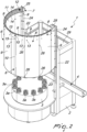
Figure 1 is a perspective view of the machine according to the invention with a protection structure in the active condition; -
Figure 2 is a perspective view of the machine according to the invention, with the protection structure in the inactive condition; -
Figure 3 is a top plan view of the machine according to the invention; -
Figure 4 is a lateral elevation view of the machine according to the invention with the protection structure in the active condition; -
Figure 5 is a lateral elevation view of the machine according to the invention with the protection structure in the inactive condition; -
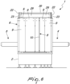
Figure 6 is a front elevation view of the machine according to the invention with the protection structure in the active condition; -
Figure 7 is a sectional view, taken along a vertical plane, of the protection structure; -
Figure 8 is an enlarged detail offigure 7 ; -
Figure 9 is a partially exploded perspective view of a portion of the protection structure; -
Figure 10 is an exploded perspective view of means for fixing components of the protection structure; -
Figure 11 is a perspective view of an insert belonging to the means for fixing components of the protection structure; -
Figure 12 is a front elevation view of the protection structure; -
Figure 13 is a sectional view, taken along the plane XIII-XIII ofFigure 12 . - With reference to the figures, the labeling machine according to the invention, generally designated by the
reference numeral 1, comprises abase structure 2 on which aconveyance carousel 3 for the containers to be labeled is mounted in a rotatable manner, said carousel being conveniently provided at its peripheral region with a plurality ofsupports 3a of the individual containers. - Conveniently, on the
base structure 2 there are aninput conveyor 4 that feeds the containers in input to theconveyor carousel 3 and anoutput conveyor 5 that picks up the containers in output from theconveyance carousel 3. - Furthermore, the machine is provided with at least one
protection structure 6, which is movable, with respect to thebase structure 2, in order to pass from an active condition, shown for example inFigure 1 , in which it prevents access from the outside to at least one portion of theconveyance carousel 3, to an inactive condition, shown for example inFigure 2 , in which it allows access from the outside to theconveyance carousel 3, so as to allow the intervention of the user on theconveyance carousel 3 or the coupling to thebase structure 2, in the desired angular position around theconveyance carousel 3, of one or more labeling assemblies, designed to apply labels on the containers that pass on theconveyance carousel 3 and are not shown for sake of simplicity, and vice versa. - According to the invention, the
protection structure 6 comprises a supportingframework 7 forcomponents 8 of theprotection structure 6, constituted in particular by at least oneclosure panel 9, which, with theprotection structure 6 in the active condition, is capable of delimiting laterally at least one portion of theconveyance carousel 3, so as to prevent access thereto from outside, and/or by at least onegrip handle 10, which allows the user to maneuver theprotection structure 6 in order to move it between the active condition and the inactive condition. - Again according to the invention, the supporting
framework 7 comprises a profiledbar 11 having an arc-like extension around the axis of theconveyance carousel 3, which is arranged above thebase structure 2 and forms at least oneengagement seat 12 formeans 13 for fixing at least one of thecomponents 8 of theprotection structure 6 to the supportingframework 7. - Advantageously, said
engagement seat 12 is constituted by one or morelongitudinal slots 14, which extend along the extension of the profiledbar 11 and allow the engagement, along their longitudinal extension, of thefixing means 13. - With this structure it is possible to connect the
closure panels 9 and/or thegrip handles 10 that compose theprotection structure 6 by fixing them to a single profiledbar 11, which by virtue of the presence of multiplelongitudinal slots 14 for the engagement of thefixing means 13, in addition to offering a valid element for anchoring thecomponents 8 of theprotection structure 6 to the supportingframework 7, with a consequent structural simplification of theprotection structure 6, offers the possibility to fix thecomponents 8 freely in any position along theprofiled bar 11. - In particular, on the
profiled bar 11 there is a plurality oflongitudinal slots 14 which are open at least on the face of the profiledbar 11 directed outward with respect to the axis of theconveyance carousel 3. It is also possible to provide on theprofiled bar 11 one or morelongitudinal slots 14 which are open on the inner side, i.e., the one directed toward theconveyance carousel 3, as well as on its sides directed downward and upward. - More particularly, at least the
longitudinal slots 14 arranged on the external face of the profiledbar 11, as well as those optionally arranged on its external face, are arranged mutually parallel and spaced along a substantially vertical direction. - With reference to the embodiment shown, the
profiled bar 11 has, in transverse cross-section, a plurality ofcentral portions 11a, with a cross-section that has a substantially polygonal shape, for example square or rectangular, axially hollow and mutually superimposed, from whichwings 11b extend diagonally in the various directions and are connected, by means of vertical joiningportions 11c, to thewings 11b of the adjacentcentral bodies 11a and delimit thelongitudinal slots 14 with pairs ofopposite wings 11d that extend from the end portions of the vertical joiningportions 11c. - Conveniently, the fixing means 13 comprise at least one
connection screw 15 which engages thecorresponding component 8 and engages, with at least one portion of itsstem 15a, a correspondinglongitudinal slot 14. - If the
component 8 is, for example, constituted by aclosure panel 9, the fixing means 13 may advantageously comprisemultiple connection screws 15 which may engage in the samelongitudinal slot 14 and/or in differentlongitudinal slots 14 of the profiledbar 11. - In particular, as highlighted in particular in
Figure 8 , theconnection screws 15 pass throughrespective holes 16 formed in theclosure panel 9, abutting, with theirhead 15b, against the external face of theclosure panel 9 and being inserted with theirstem 15a in the correspondinglongitudinal slot 14, passing through the access opening of thelongitudinal slots 14 located on the external face of the profiledbar 11. - Each
connection screw 15 is screwed in a respectivefemale thread 17 defined in acorresponding insert 18 that is accommodated in the correspondinglongitudinal slot 14. - Each
insert 18 has, conveniently, a shape in transverse cross-section that is substantially complementary to that of thelongitudinal slots 14, with, for example, a substantially cradle-like shape formed on the side directed toward thehead 15b of thecorresponding connection screw 15, and is provided, laterally to thefemale thread 17 and on mutually opposite sides, with a pair ofretention portions opposite wings 11d of the corresponding longitudinal slot, i.e., against the edge regions, directed toward the inside of the access opening of the correspondinglongitudinal slot 14. - Conveniently, a
washer 19 is interposed between thehead 15b of each one of theconnection screws 15 and thecorresponding closure panel 9 and is capable of engaging, with anaxial portion 19a, thehole 16 that is formed in theclosure panel 9 and is crossed by thecorresponding connection screw 15. Arespective lid 20 can be coupled to eachwasher 19 in order to protect thehead 15b of thecorresponding connection screw 15. - Advantageously, each
insert 18 can be provided with detachable locking means along the correspondinglongitudinal slot 14, which can, for example, comprise anengagement element 21, conveniently with a substantially spherical shape, which protrudes from theinsert 18 and is elastically pushed by a spring inserted in the body of theinsert 18, in order to be able to engage the bottom of thelongitudinal slot 14, so as to maintain theretention portions insert 18 rested against theopposite wings 11d of the profiledbar 11. - Conveniently, the
profiled bar 11 is supported, at its ends, by a pair ofuprights 22 and in particular it is capable of sliding, along the extension of theuprights 22, in order to allow the passage of theprotection structure 6 from the active condition to the inactive condition and vice versa. - As shown, the
uprights 22 extend upward from thebase structure 2 and support a respectivelinear guide 23, to which a respectiveupright element 24 of the supportingframework 7 is coupled so that it can slide. - At their upper end, the
upright elements 24 are connected torespective brackets 25 which are fixed to the ends of the profiledbar 11 by means ofconnection screws 15 which engage thelongitudinal slots 14 of the profiledbar 11. - The
closure panels 9 located proximate to the ends of the profiledbar 11 are conveniently connected also to theupright elements 24 for example by means of screws, rivets or the like. - It should be noted that the
closure panels 9 may be made of transparent plastic material, such as polycarbonate or the like, or of glass or of other material considered suitable. - For the sake of completeness, it should also be added that it is possible to provide means for mutual joining of the
closure panels 9 arranged mutually adjacent. As can be seen in particular inFigure 12 , said mutual joining means are constituted for example by a first joiningmember 26 and by a second joiningmember 27 which can be mutually coupled and act on opposite faces of theclosure panels 9. In particular, the first joiningmember 26 is provided with anabutment head 26a designed to rest against a first face of two mutuallyadjacent closure panels 9 and with astem 26b, which extends from theabutment head 26a and is designed to cross the space between the twoadjacent closure panels 9, while the second joiningmember 27 comprises alocking nut 27a designed to rest against a second face of the twoclosure panels 9, which is opposite with respect to the first face, and can be engaged with a threadedportion 26c of the first joiningmember 26, arranged at the end of thestem 26b that is opposite the one connected to theabutment head 26a. - Conveniently, the
upright elements 24 are connected at their upper end, by means of aflexible connection member 28, such as for example a belt, a cable or others, to a respective counterweight, which can slide inside the corresponding upright 22 and is not visible in the figures, in order to facilitate the manual movement of theprotection structure 6. - Conveniently, the
protection structure 6 may be provided with one ormore grip handles 10, which are conveniently provided by means of a respective metallic profile, arranged substantially vertically and provided with a substantially T-shaped transverse cross-section so as to define a grip portion, and are fixed, at least at their upper end, to the profiledbar 11 by means ofrespective connection screws 15. - It should also be noted that on the side of the
base structure 2 that is opposite with respect to the one affected by the presence of theprotection structure 6 there are advantageouslyopenable doors 29 for direct access to the region of theinput conveyor 4 and of theoutput conveyor 5. -
Such doors 29 are conveniently hinged to aperimetric frame 30 connected by means ofcrossmembers 31 to theuprights 22. - The use of the machine according to the invention is easy to understand from what has been described above.
- In practice, the user, wanting to make the region of the
base structure 2 affected by theconveyance carousel 3 accessible from the outside, will make the profiledbar 11 slide upward, along thelinear guides 23, by grabbing agrip handle 10 fixed to the profiledbar 11, so as to obtain the passage of theprotection structure 6 from the active condition to the inactive condition, with a consequent rise with respect to thebase structure 2 of theclosure panels 9 of saidprotection structure 9. - If instead the user wants to prevent access from the outside to the
conveyance carousel 3, it is sufficient for him to grip thegrip handle 10 and make theprofiled bar 11 slide downward along thelinear guides 21, until theprotection structure 9 is brought to the active condition. - In practice it has been found that the invention achieves the intended aim and objects by providing a labeling machine that has a protection structure of the conveyance carousel of the containers that is extremely practical and easy to provide.
- The invention thus conceived is susceptible of numerous modifications and variations, all of which are within the appended claims.
- In practice, the materials used, so long as they are compatible with the specific use, as well as the contingent shapes and dimensions, may be any according to the requirements and the state of the art.
- Where technical features mentioned in any claim are followed by reference signs, those reference signs have been included for the sole purpose of increasing the intelligibility of the claims and accordingly such reference signs do not have any limiting effect on the interpretation of each element identified by way of example by such reference signs.
Claims (4)
- A labeling machine comprising a base structure (2) which rotatably supports a conveyance carousel (3) for the containers to be labeled and at least one protection structure (6) which can move, with respect to said base structure (2), from an active condition, in which it prevents access from the outside to at least one portion of said conveyance carousel (3), to an inactive condition, in which it allows access from the outside to said at least one portion of said conveyance carousel (3), and vice versa, said protection structure (6) comprising a supporting framework (7) for components (8) of said protection structure (6), said supporting framework (7) comprising a profiled bar (11) having an arc-like extension around the axis of said conveyance carousel (3), which is arranged above said base structure (2) and forms at least one engagement seat (12) for means (13) for fixing to said supporting framework (7) at least one of said components (8), said at least one engagement seat (12) comprising at least one longitudinal slot (14) which extends along the extension of said profiled bar (11) and is open at least on the face of said profiled bar (11) that is directed outward with respect to the axis of said conveyance carousel (3),said fixing means (13) comprising at least one connection screw (15) which engages said at least one of said components (8) and, with at least one portion of its stem (15a), said at least one longitudinal slot (14),characterized in that said profiled bar (11) is provided with a plurality of longitudinal slots (14) for the engagement of said fixing means (13), which are arranged so as to be mutually parallel and spaced along a substantially vertical direction, and said at least one connection screw (15) is screwed into a respective female thread (17) that is formed in a corresponding insert (18) accommodated in said at least one longitudinal slot (14).
- The machine according to claim 1, characterized in that said components (8) comprise at least one closure panel (9).
- The machine according to one or more of the preceding claims, characterized in that said components (8) comprise at least one grip handle (10) in order to allow the user to move said protection structure (6) between said active condition and said inactive condition.
- The machine according to one or more of the preceding claims, characterized in that said profiled bar (11) is supported, at its ends, by a pair of uprights (22) so that it can slide along the extension of said uprights (22).
Applications Claiming Priority (2)
| Application Number | Priority Date | Filing Date | Title |
|---|---|---|---|
| IT102018000005843A IT201800005843A1 (en) | 2018-05-30 | 2018-05-30 | LABELING MACHINE. |
| PCT/EP2019/063239 WO2019228890A1 (en) | 2018-05-30 | 2019-05-22 | Labeling machine |
Publications (2)
| Publication Number | Publication Date |
|---|---|
| EP3802340A1 EP3802340A1 (en) | 2021-04-14 |
| EP3802340B1 true EP3802340B1 (en) | 2024-07-31 |
Family
ID=63244899
Family Applications (1)
| Application Number | Title | Priority Date | Filing Date |
|---|---|---|---|
| EP19724865.1A Active EP3802340B1 (en) | 2018-05-30 | 2019-05-22 | Labeling machine |
Country Status (6)
| Country | Link |
|---|---|
| US (1) | US11203456B2 (en) |
| EP (1) | EP3802340B1 (en) |
| ES (1) | ES2987786T3 (en) |
| IT (1) | IT201800005843A1 (en) |
| PL (1) | PL3802340T3 (en) |
| WO (1) | WO2019228890A1 (en) |
Families Citing this family (2)
| Publication number | Priority date | Publication date | Assignee | Title |
|---|---|---|---|---|
| IT202100013058A1 (en) * | 2021-05-20 | 2022-11-20 | Pe Labellers Spa | CONTAINER TREATMENT MACHINE. |
| WO2023041320A1 (en) * | 2021-09-14 | 2023-03-23 | P.E. Labellers S.P.A. | Labeling assembly for labeling machines |
Family Cites Families (2)
| Publication number | Priority date | Publication date | Assignee | Title |
|---|---|---|---|---|
| DE102013206679A1 (en) * | 2013-04-15 | 2014-10-16 | Krones Ag | Treatment machine for containers |
| ITUB20156259A1 (en) * | 2015-12-04 | 2017-06-04 | Pe Labellers Spa | LABELING GROUP FOR LABELING MACHINES. |
-
2018
- 2018-05-30 IT IT102018000005843A patent/IT201800005843A1/en unknown
-
2019
- 2019-05-22 PL PL19724865.1T patent/PL3802340T3/en unknown
- 2019-05-22 EP EP19724865.1A patent/EP3802340B1/en active Active
- 2019-05-22 ES ES19724865T patent/ES2987786T3/en active Active
- 2019-05-22 US US17/056,075 patent/US11203456B2/en active Active
- 2019-05-22 WO PCT/EP2019/063239 patent/WO2019228890A1/en not_active Ceased
Also Published As
| Publication number | Publication date |
|---|---|
| IT201800005843A1 (en) | 2019-11-30 |
| US11203456B2 (en) | 2021-12-21 |
| WO2019228890A1 (en) | 2019-12-05 |
| PL3802340T3 (en) | 2024-12-16 |
| BR112020023450A2 (en) | 2021-02-23 |
| EP3802340A1 (en) | 2021-04-14 |
| US20210206528A1 (en) | 2021-07-08 |
| ES2987786T3 (en) | 2024-11-18 |
Similar Documents
| Publication | Publication Date | Title |
|---|---|---|
| US11203456B2 (en) | Labeling machine | |
| EP1954905B1 (en) | System for positioning sliding doors | |
| EP3042869B1 (en) | Automated handling line guide rail assembly | |
| EP2820998B1 (en) | Basket arrangement for a dishwashing machine | |
| DK2820222T3 (en) | Covering device for a building and having a positionable handle device | |
| EP1267691B1 (en) | Shower partition | |
| EP3383750B1 (en) | Labeling assembly for labeling machines | |
| EP3112313A1 (en) | Supporting and gripping device in particular for container filling and/or capping lines | |
| US20170107748A1 (en) | Mechanism at Pivoting Window | |
| EP2907951A1 (en) | Commercial refrigerated shelf | |
| EP3064088B1 (en) | Hidden hanging bracket for the wall assembly of a structural component of a piece of furniture, with regulation from above | |
| BR112020023450B1 (en) | LABELING MACHINE | |
| DE8012428U1 (en) | Device for adjusting the balancing force on the door of a dishwasher | |
| ES2718701T3 (en) | Closure for a drive rod fitting | |
| EP1593799B1 (en) | A multi-purpose handle for window or door units | |
| KR102367863B1 (en) | Window operator for vinyl house | |
| EP2957917A1 (en) | Pipetting device with housing | |
| CN216473265U (en) | Multifunctional operating table for immune cell culture | |
| DE10237655B4 (en) | Knives, in particular laying knives | |
| EP3328244A1 (en) | Anchoring group for wall cupboards with regulation from below | |
| EP1835103B9 (en) | A hinge device for the door of a switchboard cabinet | |
| ES2313526T3 (en) | TABLE WITH SLIDING TABLE BOARD AND INSURANCE EQUIPMENT. | |
| DE102008025434B4 (en) | showcases top | |
| EP0481099A1 (en) | Pliers-type device for removing twist-off caps | |
| EP2441355A2 (en) | Show case |
Legal Events
| Date | Code | Title | Description |
|---|---|---|---|
| STAA | Information on the status of an ep patent application or granted ep patent |
Free format text: STATUS: UNKNOWN |
|
| STAA | Information on the status of an ep patent application or granted ep patent |
Free format text: STATUS: THE INTERNATIONAL PUBLICATION HAS BEEN MADE |
|
| PUAI | Public reference made under article 153(3) epc to a published international application that has entered the european phase |
Free format text: ORIGINAL CODE: 0009012 |
|
| STAA | Information on the status of an ep patent application or granted ep patent |
Free format text: STATUS: REQUEST FOR EXAMINATION WAS MADE |
|
| 17P | Request for examination filed |
Effective date: 20201222 |
|
| AK | Designated contracting states |
Kind code of ref document: A1 Designated state(s): AL AT BE BG CH CY CZ DE DK EE ES FI FR GB GR HR HU IE IS IT LI LT LU LV MC MK MT NL NO PL PT RO RS SE SI SK SM TR |
|
| AX | Request for extension of the european patent |
Extension state: BA ME |
|
| DAV | Request for validation of the european patent (deleted) | ||
| DAX | Request for extension of the european patent (deleted) | ||
| P01 | Opt-out of the competence of the unified patent court (upc) registered |
Effective date: 20230530 |
|
| GRAP | Despatch of communication of intention to grant a patent |
Free format text: ORIGINAL CODE: EPIDOSNIGR1 |
|
| STAA | Information on the status of an ep patent application or granted ep patent |
Free format text: STATUS: GRANT OF PATENT IS INTENDED |
|
| RIC1 | Information provided on ipc code assigned before grant |
Ipc: F16P 3/02 20060101ALI20240126BHEP Ipc: B65C 9/40 20060101ALI20240126BHEP Ipc: B65C 9/00 20060101AFI20240126BHEP |
|
| INTG | Intention to grant announced |
Effective date: 20240229 |
|
| GRAS | Grant fee paid |
Free format text: ORIGINAL CODE: EPIDOSNIGR3 |
|
| GRAA | (expected) grant |
Free format text: ORIGINAL CODE: 0009210 |
|
| STAA | Information on the status of an ep patent application or granted ep patent |
Free format text: STATUS: THE PATENT HAS BEEN GRANTED |
|
| AK | Designated contracting states |
Kind code of ref document: B1 Designated state(s): AL AT BE BG CH CY CZ DE DK EE ES FI FR GB GR HR HU IE IS IT LI LT LU LV MC MK MT NL NO PL PT RO RS SE SI SK SM TR |
|
| REG | Reference to a national code |
Ref country code: CH Ref legal event code: EP Ref country code: GB Ref legal event code: FG4D |
|
| REG | Reference to a national code |
Ref country code: DE Ref legal event code: R096 Ref document number: 602019056084 Country of ref document: DE |
|
| REG | Reference to a national code |
Ref country code: IE Ref legal event code: FG4D |
|
| REG | Reference to a national code |
Ref country code: NL Ref legal event code: FP |
|
| REG | Reference to a national code |
Ref country code: SE Ref legal event code: TRGR |
|
| REG | Reference to a national code |
Ref country code: ES Ref legal event code: FG2A Ref document number: 2987786 Country of ref document: ES Kind code of ref document: T3 Effective date: 20241118 |
|
| REG | Reference to a national code |
Ref country code: LT Ref legal event code: MG9D |
|
| PG25 | Lapsed in a contracting state [announced via postgrant information from national office to epo] |
Ref country code: PT Free format text: LAPSE BECAUSE OF FAILURE TO SUBMIT A TRANSLATION OF THE DESCRIPTION OR TO PAY THE FEE WITHIN THE PRESCRIBED TIME-LIMIT Effective date: 20241202 |
|
| PG25 | Lapsed in a contracting state [announced via postgrant information from national office to epo] |
Ref country code: PT Free format text: LAPSE BECAUSE OF FAILURE TO SUBMIT A TRANSLATION OF THE DESCRIPTION OR TO PAY THE FEE WITHIN THE PRESCRIBED TIME-LIMIT Effective date: 20241202 |
|
| PG25 | Lapsed in a contracting state [announced via postgrant information from national office to epo] |
Ref country code: NO Free format text: LAPSE BECAUSE OF FAILURE TO SUBMIT A TRANSLATION OF THE DESCRIPTION OR TO PAY THE FEE WITHIN THE PRESCRIBED TIME-LIMIT Effective date: 20241031 |
|
| PG25 | Lapsed in a contracting state [announced via postgrant information from national office to epo] |
Ref country code: FI Free format text: LAPSE BECAUSE OF FAILURE TO SUBMIT A TRANSLATION OF THE DESCRIPTION OR TO PAY THE FEE WITHIN THE PRESCRIBED TIME-LIMIT Effective date: 20240731 Ref country code: GR Free format text: LAPSE BECAUSE OF FAILURE TO SUBMIT A TRANSLATION OF THE DESCRIPTION OR TO PAY THE FEE WITHIN THE PRESCRIBED TIME-LIMIT Effective date: 20241101 |
|
| PG25 | Lapsed in a contracting state [announced via postgrant information from national office to epo] |
Ref country code: BG Free format text: LAPSE BECAUSE OF FAILURE TO SUBMIT A TRANSLATION OF THE DESCRIPTION OR TO PAY THE FEE WITHIN THE PRESCRIBED TIME-LIMIT Effective date: 20240731 |
|
| PG25 | Lapsed in a contracting state [announced via postgrant information from national office to epo] |
Ref country code: LV Free format text: LAPSE BECAUSE OF FAILURE TO SUBMIT A TRANSLATION OF THE DESCRIPTION OR TO PAY THE FEE WITHIN THE PRESCRIBED TIME-LIMIT Effective date: 20240731 |
|
| PG25 | Lapsed in a contracting state [announced via postgrant information from national office to epo] |
Ref country code: IS Free format text: LAPSE BECAUSE OF FAILURE TO SUBMIT A TRANSLATION OF THE DESCRIPTION OR TO PAY THE FEE WITHIN THE PRESCRIBED TIME-LIMIT Effective date: 20241130 |
|
| PG25 | Lapsed in a contracting state [announced via postgrant information from national office to epo] |
Ref country code: HR Free format text: LAPSE BECAUSE OF FAILURE TO SUBMIT A TRANSLATION OF THE DESCRIPTION OR TO PAY THE FEE WITHIN THE PRESCRIBED TIME-LIMIT Effective date: 20240731 |
|
| PG25 | Lapsed in a contracting state [announced via postgrant information from national office to epo] |
Ref country code: RS Free format text: LAPSE BECAUSE OF FAILURE TO SUBMIT A TRANSLATION OF THE DESCRIPTION OR TO PAY THE FEE WITHIN THE PRESCRIBED TIME-LIMIT Effective date: 20241031 |
|
| PG25 | Lapsed in a contracting state [announced via postgrant information from national office to epo] |
Ref country code: RS Free format text: LAPSE BECAUSE OF FAILURE TO SUBMIT A TRANSLATION OF THE DESCRIPTION OR TO PAY THE FEE WITHIN THE PRESCRIBED TIME-LIMIT Effective date: 20241031 Ref country code: NO Free format text: LAPSE BECAUSE OF FAILURE TO SUBMIT A TRANSLATION OF THE DESCRIPTION OR TO PAY THE FEE WITHIN THE PRESCRIBED TIME-LIMIT Effective date: 20241031 Ref country code: LV Free format text: LAPSE BECAUSE OF FAILURE TO SUBMIT A TRANSLATION OF THE DESCRIPTION OR TO PAY THE FEE WITHIN THE PRESCRIBED TIME-LIMIT Effective date: 20240731 Ref country code: IS Free format text: LAPSE BECAUSE OF FAILURE TO SUBMIT A TRANSLATION OF THE DESCRIPTION OR TO PAY THE FEE WITHIN THE PRESCRIBED TIME-LIMIT Effective date: 20241130 Ref country code: HR Free format text: LAPSE BECAUSE OF FAILURE TO SUBMIT A TRANSLATION OF THE DESCRIPTION OR TO PAY THE FEE WITHIN THE PRESCRIBED TIME-LIMIT Effective date: 20240731 Ref country code: GR Free format text: LAPSE BECAUSE OF FAILURE TO SUBMIT A TRANSLATION OF THE DESCRIPTION OR TO PAY THE FEE WITHIN THE PRESCRIBED TIME-LIMIT Effective date: 20241101 Ref country code: FI Free format text: LAPSE BECAUSE OF FAILURE TO SUBMIT A TRANSLATION OF THE DESCRIPTION OR TO PAY THE FEE WITHIN THE PRESCRIBED TIME-LIMIT Effective date: 20240731 Ref country code: BG Free format text: LAPSE BECAUSE OF FAILURE TO SUBMIT A TRANSLATION OF THE DESCRIPTION OR TO PAY THE FEE WITHIN THE PRESCRIBED TIME-LIMIT Effective date: 20240731 |
|
| PG25 | Lapsed in a contracting state [announced via postgrant information from national office to epo] |
Ref country code: SM Free format text: LAPSE BECAUSE OF FAILURE TO SUBMIT A TRANSLATION OF THE DESCRIPTION OR TO PAY THE FEE WITHIN THE PRESCRIBED TIME-LIMIT Effective date: 20240731 Ref country code: RO Free format text: LAPSE BECAUSE OF FAILURE TO SUBMIT A TRANSLATION OF THE DESCRIPTION OR TO PAY THE FEE WITHIN THE PRESCRIBED TIME-LIMIT Effective date: 20240731 Ref country code: DK Free format text: LAPSE BECAUSE OF FAILURE TO SUBMIT A TRANSLATION OF THE DESCRIPTION OR TO PAY THE FEE WITHIN THE PRESCRIBED TIME-LIMIT Effective date: 20240731 |
|
| PG25 | Lapsed in a contracting state [announced via postgrant information from national office to epo] |
Ref country code: EE Free format text: LAPSE BECAUSE OF FAILURE TO SUBMIT A TRANSLATION OF THE DESCRIPTION OR TO PAY THE FEE WITHIN THE PRESCRIBED TIME-LIMIT Effective date: 20240731 |
|
| PG25 | Lapsed in a contracting state [announced via postgrant information from national office to epo] |
Ref country code: CZ Free format text: LAPSE BECAUSE OF FAILURE TO SUBMIT A TRANSLATION OF THE DESCRIPTION OR TO PAY THE FEE WITHIN THE PRESCRIBED TIME-LIMIT Effective date: 20240731 |
|
| PG25 | Lapsed in a contracting state [announced via postgrant information from national office to epo] |
Ref country code: SK Free format text: LAPSE BECAUSE OF FAILURE TO SUBMIT A TRANSLATION OF THE DESCRIPTION OR TO PAY THE FEE WITHIN THE PRESCRIBED TIME-LIMIT Effective date: 20240731 |
|
| REG | Reference to a national code |
Ref country code: DE Ref legal event code: R097 Ref document number: 602019056084 Country of ref document: DE |
|
| PLBE | No opposition filed within time limit |
Free format text: ORIGINAL CODE: 0009261 |
|
| STAA | Information on the status of an ep patent application or granted ep patent |
Free format text: STATUS: NO OPPOSITION FILED WITHIN TIME LIMIT |
|
| PGFP | Annual fee paid to national office [announced via postgrant information from national office to epo] |
Ref country code: NL Payment date: 20250516 Year of fee payment: 7 |
|
| 26N | No opposition filed |
Effective date: 20250501 |
|
| PGFP | Annual fee paid to national office [announced via postgrant information from national office to epo] |
Ref country code: DE Payment date: 20250516 Year of fee payment: 7 Ref country code: PL Payment date: 20250509 Year of fee payment: 7 |
|
| PGFP | Annual fee paid to national office [announced via postgrant information from national office to epo] |
Ref country code: GB Payment date: 20250520 Year of fee payment: 7 Ref country code: ES Payment date: 20250605 Year of fee payment: 7 |
|
| PGFP | Annual fee paid to national office [announced via postgrant information from national office to epo] |
Ref country code: FR Payment date: 20250520 Year of fee payment: 7 |
|
| PGFP | Annual fee paid to national office [announced via postgrant information from national office to epo] |
Ref country code: AT Payment date: 20250516 Year of fee payment: 7 |
|
| PGFP | Annual fee paid to national office [announced via postgrant information from national office to epo] |
Ref country code: TR Payment date: 20250515 Year of fee payment: 7 |
|
| PGFP | Annual fee paid to national office [announced via postgrant information from national office to epo] |
Ref country code: SE Payment date: 20250519 Year of fee payment: 7 |
|
| REG | Reference to a national code |
Ref country code: CH Ref legal event code: H13 Free format text: ST27 STATUS EVENT CODE: U-0-0-H10-H13 (AS PROVIDED BY THE NATIONAL OFFICE) Effective date: 20251223 |
|
| PG25 | Lapsed in a contracting state [announced via postgrant information from national office to epo] |
Ref country code: LU Free format text: LAPSE BECAUSE OF NON-PAYMENT OF DUE FEES Effective date: 20250522 |
|
| PG25 | Lapsed in a contracting state [announced via postgrant information from national office to epo] |
Ref country code: CH Free format text: LAPSE BECAUSE OF NON-PAYMENT OF DUE FEES Effective date: 20250531 |
|
| REG | Reference to a national code |
Ref country code: BE Ref legal event code: MM Effective date: 20250531 |
|
| PG25 | Lapsed in a contracting state [announced via postgrant information from national office to epo] |
Ref country code: MC Free format text: LAPSE BECAUSE OF FAILURE TO SUBMIT A TRANSLATION OF THE DESCRIPTION OR TO PAY THE FEE WITHIN THE PRESCRIBED TIME-LIMIT Effective date: 20240731 |
|
| REG | Reference to a national code |
Ref country code: AT Ref legal event code: UEP Ref document number: 1708274 Country of ref document: AT Kind code of ref document: T Effective date: 20240731 |
|
| PG25 | Lapsed in a contracting state [announced via postgrant information from national office to epo] |
Ref country code: IE Free format text: LAPSE BECAUSE OF NON-PAYMENT OF DUE FEES Effective date: 20250522 |
|
| PG25 | Lapsed in a contracting state [announced via postgrant information from national office to epo] |
Ref country code: BE Free format text: LAPSE BECAUSE OF NON-PAYMENT OF DUE FEES Effective date: 20250531 |
|
| PGFP | Annual fee paid to national office [announced via postgrant information from national office to epo] |
Ref country code: IT Payment date: 20260320 Year of fee payment: 8 |