EP3801918B1 - A centrifugal separator - Google Patents
A centrifugal separator Download PDFInfo
- Publication number
- EP3801918B1 EP3801918B1 EP19725989.8A EP19725989A EP3801918B1 EP 3801918 B1 EP3801918 B1 EP 3801918B1 EP 19725989 A EP19725989 A EP 19725989A EP 3801918 B1 EP3801918 B1 EP 3801918B1
- Authority
- EP
- European Patent Office
- Prior art keywords
- discs
- milk
- distance
- separator
- range
- Prior art date
- Legal status (The legal status is an assumption and is not a legal conclusion. Google has not performed a legal analysis and makes no representation as to the accuracy of the status listed.)
- Active
Links
Images

Classifications
-
- A—HUMAN NECESSITIES
- A23—FOODS OR FOODSTUFFS; TREATMENT THEREOF, NOT COVERED BY OTHER CLASSES
- A23C—DAIRY PRODUCTS, e.g. MILK, BUTTER OR CHEESE; MILK OR CHEESE SUBSTITUTES; PREPARATION THEREOF
- A23C9/00—Milk preparations; Milk powder or milk powder preparations
- A23C9/14—Milk preparations; Milk powder or milk powder preparations in which the chemical composition of the milk is modified by non-chemical treatment
-
- B—PERFORMING OPERATIONS; TRANSPORTING
- B04—CENTRIFUGAL APPARATUS OR MACHINES FOR CARRYING-OUT PHYSICAL OR CHEMICAL PROCESSES
- B04B—CENTRIFUGES
- B04B1/00—Centrifuges with rotary bowls provided with solid jackets for separating predominantly liquid mixtures with or without solid particles
- B04B1/04—Centrifuges with rotary bowls provided with solid jackets for separating predominantly liquid mixtures with or without solid particles with inserted separating walls
- B04B1/08—Centrifuges with rotary bowls provided with solid jackets for separating predominantly liquid mixtures with or without solid particles with inserted separating walls of conical shape
-
- B—PERFORMING OPERATIONS; TRANSPORTING
- B04—CENTRIFUGAL APPARATUS OR MACHINES FOR CARRYING-OUT PHYSICAL OR CHEMICAL PROCESSES
- B04B—CENTRIFUGES
- B04B7/00—Elements of centrifuges
- B04B7/08—Rotary bowls
- B04B7/12—Inserts, e.g. armouring plates
- B04B7/14—Inserts, e.g. armouring plates for separating walls of conical shape
Definitions
- the invention relates to a method using a centrifugal separator for separating cold milk into a cream phase and a skim milk phase.
- centrifugal separators Separators for separating milk into different phases of varying density under the influence of a centrifugal force are called centrifugal separators.
- the milk is introduced in a rotating disc stack of the centrifugal separator.
- heavier components and lighter fat globules in the raw milk begin to settle radially outwards respectively inwards in the separation channels according to their density.
- the cream i.e. the fat globules, has a lower density than the skimmilk and therefore moves inwards over the disks, towards the separator's axis of rotation.
- the cream continues to an axial outlet and the heavier phase, i.e.
- the separator comprises a centrifuge bowl and a disc stack of conical discs arranged inside the centrifuge bowl.
- the disc stack comprises a first set of discs, and a second set of discs.
- the discs in the disk stack comprises distribution openings such that the milk passes the first set of discs before passing the second set of discs.
- the discs in the first set of discs are separated from each other by a first distance, and the discs in the second set of discs are separated from each other by a second distance which is smaller than the first distance.
- the method of separating cold milk uses the separator.
- the method comprises providing a flow of the milk through a first set of discs in a disc stack arranged in the separator, and providing a flow of the milk through a second set of discs, stacked on top of the first set of discs.
- first and second set of discs where the discs in the second set are separated from each other by a distance which is smaller than the distance between discs in the first set allows for an initial separation of larger flat globules from the milk in the first set of discs, with a lowered risk for build-up of fat between the discs, while the smaller separation in the second set of discs provides for maintaining a high skimming efficiency.
- Fig. 1 is a schematic illustration of a separator 100 for separating milk (RM) into a cream phase (CR) and a skim milk phase (SM).
- the separator 100 comprises a centrifuge bowl 101 and a disc stack 102 of conical discs 103 arranged inside the centrifuge bowl 101.
- the milk (RM) which typically is so called raw milk, enters the centrifuge bowl 101 via an inlet 113, and is subsequently separated into the skim milk phase (SM) and the cream phase (CR) at the top of the centrifuge bowl 101.
- SM skim milk phase
- CR cream phase
- RM milk flows from the inlet 113 into distribution openings 117 in the disc stack 102, and the cream phase (CR) is centrifuged towards a center portion 118 or the disk stack 102 and flows from the center portion 118 to a cream phase outlet 115, whereas the skimmed milk phase (SM) is centrifuged towards a periphery 119 of the disc stack 102 and flows from the periphery 119 to an outlet 114 for the skimmed milk phase (SM).
- CR cream phase
- SM skimmed milk phase
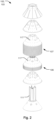
- Fig. 2 and Fig. 3 show an example of the disc stack 102 in an exploded perspective view.
- the disc stack 102 comprises a first set of discs 106 and a second set of discs 107.
- the discs 103 in the disk stack 102 comprises the aforementioned distribution openings 117 such that the milk (RM) passes the first set of discs 106 before passing the second set of discs 107.
- the discs 103 in the first set of discs 106 are separated from each other by a first distance 108, and the discs 103 in the second set of discs 107 are separated from each other by a second distance 109.
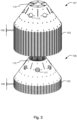
- Fig. 3 is a further detailed perspective view of the first and second sets of discs 106, 107, having respective separation distances 108 and 109.
- the second distance 109 is smaller than the first distance 108. I.e. the spacing between the discs 103 in the second set of discs 107 is smaller than the spacing between the discs 103 in the first set of discs 106.
- the distance or spacing between the discs 103 in the first and second sets 106, 107, is sometimes also referred to as the caulk height.
- the caulk height in the second set of discs 107 is thus smaller than the caulk height in the first set of discs 106.
- the number of discs 103 in the second set of discs 107 may be higher than the number of discs 103 in the first set of discs 106, as schematically illustrated in Fig. 3 .
- This provides for achieving a high skimming efficiency, as the number of discs 103 in the second set 107 can be increased more by having a smaller separation distance 109, compared to the discs 103 in the first set 106, for a given size of the separator 100.
- the discs 108 of the first set 106 provides for the initial separation of larger fat globules as described above, although being fewer in number than the discs 103 of the second set 107.
- a compact separator 100 with increased low temperature efficiency may thus be provided.
- a ratio between the number of discs 103 in the second set of discs 107 to the number of discs 103 in the first set of discs 106 may be in the range of 2 - 6. This allows for a reduced risk of fat occlusion in the disc stack 102 while the skimming efficiency is increased.
- the ratio between the number of discs 103 in the second set of discs 107 to the number of discs 103 in the first set of discs 106 may be in the range of or 3 - 5, which provides for a separator 100 which is particular advantageous in terms of skimming efficiency.
- the number of discs 103 in the first set of discs 106, having the increased separation distance 108, may be in the range of 20 - 50 discs. Having a number of discs 103 of the first set 106 in this range provides for facilitating the initial separation of fat globules with a lowered risk of blockage by fat between the discs 103. At the same time this allows for having a plurality of discs 103 in the second set 109 that increases the skimming performance for a given size of the separator 100. In one example the number of discs 103 in the first set of discs 106 is in the range 35 - 40, and the number of discs 103 in the second set of discs 107 is in the range 145 - 165.
- a ratio between the first distance 108 to the second distance 109 may be in the range of 1,2 - 2,4. I.e. the first set of discs 106 are separated from each other by a first distance 108 which is larger than the separation distance 109 between the discs 103 of the second set 107 by a factor which is in the range 1,2 - 2,4. This provides for an increased skimming performance at low temperature conditions.
- a ratio between the first distance 108 to the second distance 109 in the range of 1,25 - 1,60 provides for a particularly advantageous separator 100 with an increased skimming performance at low temperatures for a given volume of the separator 100.
- the ratio between the first distance 108 to the second distance 109 may be 1,33 for an optimized skimming efficiency of the separator 100 in some low temperature operating conditions.
- the discs 103 in the first set of discs 106 are separated by 0,75 - 0,85 mm. Having a separation of the discs 103 in the first set 106 in this range provides for a particular advantageous separation of larger fat globules in the milk with a further reduced risk of occluding the space between the discs 103 with fat.
- the discs 103 in the second set of discs 107 are separated by 0,55 - 0,65 mm. Having a separation of the discs 103 in the second set 107 in this range, e.g. in combination with a separation in the range 0,75 - 0,85 mm of the first set 106, allows at the same time for increasing the overall skimming performance for a given volume of the separator 100 while avoiding blockage problems when separating milk of low temperature.
- the discs 103 in the first and second sets 106, 107 may be separated by 0,8 mm and 0,6 mm, respectively, for an optimized performance in some operating conditions, e.g. with a temperature of the milk in the range of 10 - 18 °C.
- the discs 103 in the first set of discs 106 may have an open center portion 110 for receiving a centering element 111 arranged in the centrifuge bowl 101.
- the open center portion 110 in the first set of discs 106 is illustrated in the example of Fig. 3 , and the centering element 111 is shown in Fig. 2 .
- the discs 103 in the first set 103 may thus be accurately aligned with the axis of rotation of the centrifuge bowl 101.
- the discs 103 in the second set of discs 107 may have a reduced diameter center portion 112 coaxially aligned with the open center portion 110 of the discs 103 in the first set of discs 106.
- the reduced diameter center portion 112 of the discs 103 in the second set 107 is shown in the example of Fig. 3 .
- the opening in the center of the discs 103 of the second set 107 is partly closed in comparison to the discs 103 in the first set 106.
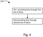
- Fig. 4 illustrates a flow chart of a method 200 of separating cold milk using a separator 100 as described above in relation to Figs. 1 - 3 .
- the method 200 comprises providing 201 a flow of the milk through a first set of discs 106 in a disc stack 102 arranged in the separator 100, and providing 202 a flow of the milk through a second set of discs 107, stacked on top of the first set of discs 106.
- the discs 103 in the first set of discs 106 are separated from each other by a first distance 108, and the discs 103 in the second set of discs 107 are separated from each other by a second distance 109 which is smaller than the first distance 108.
- the method 200 thus allows for an efficient separation of cold milk with a reduced risk of blockage in the disc stack 102 by the fat in the milk, as described above in relation to the separator 100 and Figs. 1-3 .
- the cold milk may be milk which is not heated.
- the temperature of the cold milk is below 30°C or below 20°C in some examples.
- the temperature of the cold milk may also be below 17°C or below 14°C in some examples.
- the temperature of the cold milk may also be below 13°C or below 10°C in some examples.
- the tendency of the fat to form larger aggregates of fat particles may increase with the lowering of the temperature.
- the separator 100 provides for a particularly advantageous increase in skimming efficiency and reduced risk of such fat blockage of fat blockage as the temperature of the milk is reduced further across the ranges as exemplified above.
Landscapes
- Life Sciences & Earth Sciences (AREA)
- Chemical & Material Sciences (AREA)
- Engineering & Computer Science (AREA)
- Food Science & Technology (AREA)
- Polymers & Plastics (AREA)
- Dairy Products (AREA)
- Centrifugal Separators (AREA)
Description
- The invention relates to a method using a centrifugal separator for separating cold milk into a cream phase and a skim milk phase.
- Separators for separating milk into different phases of varying density under the influence of a centrifugal force are called centrifugal separators. The milk is introduced in a rotating disc stack of the centrifugal separator. Under the influence of the centrifugal force, heavier components and lighter fat globules in the raw milk begin to settle radially outwards respectively inwards in the separation channels according to their density. The cream, i.e. the fat globules, has a lower density than the skimmilk and therefore moves inwards over the disks, towards the separator's axis of rotation. The cream continues to an axial outlet and the heavier phase, i.e. the skimmilk, moves outwards to the space outside the disc stack and from there to a skimmilk outlet. A problem with previous separators is that the efficiency is reduced in certain operating conditions. For example, the skimming performance may be reduced under low temperature conditions. Related prior art is described in patent documents
DD287874A5 DD288322A5 - It is an object of the invention to at least partly overcome one or more limitations of the prior art. In particular, it is an object to provide an improved method of separating cold milk, in particular allowing for an improved skimming performance over a wider temperature range and which requires less maintenance.
- This is achieved by a method using a centrifugal separator for separating milk into a cream phase and a skim milk phase. The separator comprises a centrifuge bowl and a disc stack of conical discs arranged inside the centrifuge bowl. The disc stack comprises a first set of discs, and a second set of discs. The discs in the disk stack comprises distribution openings such that the milk passes the first set of discs before passing the second set of discs. The discs in the first set of discs are separated from each other by a first distance, and the discs in the second set of discs are separated from each other by a second distance which is smaller than the first distance.
- According to the invention the method of separating cold milk uses the separator. The method comprises providing a flow of the milk through a first set of discs in a disc stack arranged in the separator, and providing a flow of the milk through a second set of discs, stacked on top of the first set of discs.
- Having first and second set of discs where the discs in the second set are separated from each other by a distance which is smaller than the distance between discs in the first set allows for an initial separation of larger flat globules from the milk in the first set of discs, with a lowered risk for build-up of fat between the discs, while the smaller separation in the second set of discs provides for maintaining a high skimming efficiency.
- Still other objectives, features, aspects and advantages of the invention will appear from the following detailed description as well as from the drawings.
- Embodiments of the invention will now be described, by way of example, with reference to the accompanying schematic drawings.
-
Fig. 1 is a cross-sectional side view of a centrifugal separator for separating milk into a cream phase and a skim milk phase; -
Fig. 2 is an exploded perspective view of a centrifugal separator with a disc stack having first and second sets of discs; -
Fig. 3 is a further detailed perspective view of first and second sets of discs in the disc stack; and -
Fig. 4 is a flowchart of a method of separating cold milk. - Embodiments of the invention will now be described more fully hereinafter with reference to the accompanying drawings, in which some, but not all, embodiments of the invention are shown. The invention may be embodied in many different forms and should not be construed as limited to the embodiments set forth herein.
-
Fig. 1 is a schematic illustration of aseparator 100 for separating milk (RM) into a cream phase (CR) and a skim milk phase (SM). Theseparator 100 comprises acentrifuge bowl 101 and adisc stack 102 ofconical discs 103 arranged inside thecentrifuge bowl 101. The milk (RM), which typically is so called raw milk, enters thecentrifuge bowl 101 via aninlet 113, and is subsequently separated into the skim milk phase (SM) and the cream phase (CR) at the top of thecentrifuge bowl 101. I.e. milk (RM) flows from theinlet 113 intodistribution openings 117 in thedisc stack 102, and the cream phase (CR) is centrifuged towards acenter portion 118 or thedisk stack 102 and flows from thecenter portion 118 to acream phase outlet 115, whereas the skimmed milk phase (SM) is centrifuged towards aperiphery 119 of thedisc stack 102 and flows from theperiphery 119 to anoutlet 114 for the skimmed milk phase (SM). -
Fig. 2 andFig. 3 show an example of thedisc stack 102 in an exploded perspective view. Thedisc stack 102 comprises a first set ofdiscs 106 and a second set ofdiscs 107. Thediscs 103 in thedisk stack 102 comprises theaforementioned distribution openings 117 such that the milk (RM) passes the first set ofdiscs 106 before passing the second set ofdiscs 107. Thediscs 103 in the first set ofdiscs 106 are separated from each other by afirst distance 108, and thediscs 103 in the second set ofdiscs 107 are separated from each other by asecond distance 109.Fig. 3 is a further detailed perspective view of the first and second sets ofdiscs respective separation distances second distance 109 is smaller than thefirst distance 108. I.e. the spacing between thediscs 103 in the second set ofdiscs 107 is smaller than the spacing between thediscs 103 in the first set ofdiscs 106. The distance or spacing between thediscs 103 in the first andsecond sets discs 107 is thus smaller than the caulk height in the first set ofdiscs 106. Havingdiscs 103 in thefirst set 106 which are separated from each other by a distance which is larger than the distance between thediscs 103 in thesecond set 107 allows for an initial separation of larger flat globules from the milk in the first set ofdiscs 106, with a lowered risk for build-up of fat between thediscs 103 due to the larger separation thereof, while the smaller separation in the second set ofdiscs 107 provides for maintaining a high skimming efficiency for a given size of theseparator 100. When the milk flows into the second set ofdiscs 107, the fat globules has decreased in amount and/or size. The risk of occlusion or plugging of fat in thedisc stack 102 is thus reduced while a high efficiency can be provided. This is particularly advantageous in low temperature conditions where the milk is not heated, as the tendency for accumulation of the fat is increased in these cases. As the risk of fat occlusion is reduced, there is also a reduced need for cleaning thedisc stack 102. I.e. less resources has to be spend on the maintenance of theseparator 100, and the throughput in the production line can also be increased due to less interruptions from maintenance operations. - The number of
discs 103 in the second set ofdiscs 107 may be higher than the number ofdiscs 103 in the first set ofdiscs 106, as schematically illustrated inFig. 3 . This provides for achieving a high skimming efficiency, as the number ofdiscs 103 in thesecond set 107 can be increased more by having asmaller separation distance 109, compared to thediscs 103 in thefirst set 106, for a given size of theseparator 100. At the same time, thediscs 108 of thefirst set 106 provides for the initial separation of larger fat globules as described above, although being fewer in number than thediscs 103 of thesecond set 107. Acompact separator 100 with increased low temperature efficiency may thus be provided. - A ratio between the number of
discs 103 in the second set ofdiscs 107 to the number ofdiscs 103 in the first set ofdiscs 106 may be in the range of 2 - 6. This allows for a reduced risk of fat occlusion in thedisc stack 102 while the skimming efficiency is increased. The ratio between the number ofdiscs 103 in the second set ofdiscs 107 to the number ofdiscs 103 in the first set ofdiscs 106 may be in the range of or 3 - 5, which provides for aseparator 100 which is particular advantageous in terms of skimming efficiency. - The number of
discs 103 in the first set ofdiscs 106, having the increasedseparation distance 108, may be in the range of 20 - 50 discs. Having a number ofdiscs 103 of thefirst set 106 in this range provides for facilitating the initial separation of fat globules with a lowered risk of blockage by fat between thediscs 103. At the same time this allows for having a plurality ofdiscs 103 in thesecond set 109 that increases the skimming performance for a given size of theseparator 100. In one example the number ofdiscs 103 in the first set ofdiscs 106 is in the range 35 - 40, and the number ofdiscs 103 in the second set ofdiscs 107 is in the range 145 - 165. - A ratio between the
first distance 108 to thesecond distance 109 may be in the range of 1,2 - 2,4. I.e. the first set ofdiscs 106 are separated from each other by afirst distance 108 which is larger than theseparation distance 109 between thediscs 103 of thesecond set 107 by a factor which is in the range 1,2 - 2,4. This provides for an increased skimming performance at low temperature conditions. A ratio between thefirst distance 108 to thesecond distance 109 in the range of 1,25 - 1,60 provides for a particularlyadvantageous separator 100 with an increased skimming performance at low temperatures for a given volume of theseparator 100. - In one example the ratio between the
first distance 108 to thesecond distance 109 may be 1,33 for an optimized skimming efficiency of theseparator 100 in some low temperature operating conditions. - The
discs 103 in the first set ofdiscs 106 are separated by 0,75 - 0,85 mm. Having a separation of thediscs 103 in thefirst set 106 in this range provides for a particular advantageous separation of larger fat globules in the milk with a further reduced risk of occluding the space between thediscs 103 with fat. - The
discs 103 in the second set ofdiscs 107 are separated by 0,55 - 0,65 mm. Having a separation of thediscs 103 in thesecond set 107 in this range, e.g. in combination with a separation in the range 0,75 - 0,85 mm of thefirst set 106, allows at the same time for increasing the overall skimming performance for a given volume of theseparator 100 while avoiding blockage problems when separating milk of low temperature. In one example thediscs 103 in the first andsecond sets - The
discs 103 in the first set ofdiscs 106 may have anopen center portion 110 for receiving a centeringelement 111 arranged in thecentrifuge bowl 101. Theopen center portion 110 in the first set ofdiscs 106 is illustrated in the example ofFig. 3 , and the centeringelement 111 is shown inFig. 2 . Thediscs 103 in thefirst set 103 may thus be accurately aligned with the axis of rotation of thecentrifuge bowl 101. - The
discs 103 in the second set ofdiscs 107 may have a reduceddiameter center portion 112 coaxially aligned with theopen center portion 110 of thediscs 103 in the first set ofdiscs 106. The reduceddiameter center portion 112 of thediscs 103 in thesecond set 107 is shown in the example ofFig. 3 . In this example the opening in the center of thediscs 103 of thesecond set 107 is partly closed in comparison to thediscs 103 in thefirst set 106. -
Fig. 4 illustrates a flow chart of amethod 200 of separating cold milk using aseparator 100 as described above in relation toFigs. 1 - 3 . Themethod 200 comprises providing 201 a flow of the milk through a first set ofdiscs 106 in adisc stack 102 arranged in theseparator 100, and providing 202 a flow of the milk through a second set ofdiscs 107, stacked on top of the first set ofdiscs 106. Thediscs 103 in the first set ofdiscs 106 are separated from each other by afirst distance 108, and thediscs 103 in the second set ofdiscs 107 are separated from each other by asecond distance 109 which is smaller than thefirst distance 108. Themethod 200 thus allows for an efficient separation of cold milk with a reduced risk of blockage in thedisc stack 102 by the fat in the milk, as described above in relation to theseparator 100 andFigs. 1-3 . - The cold milk may be milk which is not heated. The temperature of the cold milk is below 30°C or below 20°C in some examples. The temperature of the cold milk may also be below 17°C or below 14°C in some examples. The temperature of the cold milk may also be below 13°C or below 10°C in some examples. The tendency of the fat to form larger aggregates of fat particles may increase with the lowering of the temperature. Thus, the
separator 100 provides for a particularly advantageous increase in skimming efficiency and reduced risk of such fat blockage of fat blockage as the temperature of the milk is reduced further across the ranges as exemplified above. - From the description above follows that, although various embodiments of the invention have been described and shown, the invention is not restricted thereto, but may also be embodied in other ways within the scope of the subject-matter defined in the following claims.
Claims (12)
- A method (200) of separating cold milk, the methodusing a centrifugal separator (100) for separating milk (RM) into a cream phase (CR) and a skim milk phase (SM), the separator (100) comprising a centrifuge bowl (101), a disc stack (102) of conical discs (103) arranged inside the centrifuge bowl (101), the disc stack (102) comprising a first set of discs (106) and a second set of discs (107), the discs (103) in the disk stack (102) comprising distribution openings (117) such that the milk (RM) passes the first set of discs (106) before passing the second set of discs (107), the discs (103) in the first set of discs (106) being separated from each other by a first distance (108), and the discs (103) in the second set of discs (107) being separated from each other by a second distance (109) which is smaller than the first distance (108),the method comprisingproviding (201) a flow of the milk through the first set of discs (106) in the disc stack (102) arranged in the separator (100), and thereafterproviding (202) the flow of the milk through the second set of discs (107), which is stacked on top of the first set of discs (106), characterized in thatthe discs (103) in the first set of discs (106) are separated by 0,75 to 0,85 mm and the discs (103) in the second set of discs (107) are separated by 0,55 to 0,65 mm, andthe temperature of the cold milk is below 30 °C.
- A method according to claim 1, wherein the cold milk is milk which is not heated.
- A method according to claim 2, wherein the temperature of the cold milk is below 20 °C.
- A method according to claim 2, wherein the temperature of the cold milk is below 17 °C, or below 14 °C.
- A method according to claim 2, wherein the temperature of the cold milk is below 13 °C, or below 10 °C.
- A method according to any preceding claim, wherein the number of discs (103) in the second set of discs (107) is higher than the number of discs (103) in the first set of discs (106).
- A method according to any preceding claim, wherein a ratio between the number of discs (103) in the second set of discs (107) to the number of discs (103) in the first set of discs (106) is in the range of 2 to 6, or in the range of 3 to 5.
- A method according to any preceding claim, wherein the number of discs (103) in the first set of discs (106) is in the range of 20 to 50 discs.
- A method according to any preceding claim, wherein a ratio between the first distance (108) and the second distance (109) is in the range of 1,2 - 2,4, or in the range of 1,25 - 1,60.
- A method according to any preceding claim, wherein the ratio between the first distance (108) and the second distance (109) is 1,33.
- A method according to any preceding claim, wherein discs (103) in the first set of discs (106) have an open center portion (110) for receiving a centering element (111) arranged in the centrifuge bowl (101).
- A method according to any preceding claim, wherein the discs (103) in the second set of discs (107) have a reduced diameter center portion (112) coaxially aligned with the open center portion (110) of the discs (103) in the first set of discs (106).
Applications Claiming Priority (2)
| Application Number | Priority Date | Filing Date | Title |
|---|---|---|---|
| US15/989,709 US11331679B2 (en) | 2018-05-25 | 2018-05-25 | Centrifugal separator |
| PCT/EP2019/063215 WO2019224247A1 (en) | 2018-05-25 | 2019-05-22 | A centrifugal separator |
Publications (3)
| Publication Number | Publication Date |
|---|---|
| EP3801918A1 EP3801918A1 (en) | 2021-04-14 |
| EP3801918B1 true EP3801918B1 (en) | 2025-01-22 |
| EP3801918C0 EP3801918C0 (en) | 2025-01-22 |
Family
ID=66640983
Family Applications (1)
| Application Number | Title | Priority Date | Filing Date |
|---|---|---|---|
| EP19725989.8A Active EP3801918B1 (en) | 2018-05-25 | 2019-05-22 | A centrifugal separator |
Country Status (4)
| Country | Link |
|---|---|
| US (1) | US11331679B2 (en) |
| EP (1) | EP3801918B1 (en) |
| CN (1) | CN112188932B (en) |
| WO (1) | WO2019224247A1 (en) |
Families Citing this family (2)
| Publication number | Priority date | Publication date | Assignee | Title |
|---|---|---|---|---|
| WO2021018540A1 (en) * | 2019-07-26 | 2021-02-04 | Tetra Laval Holdings & Finance S.A. | A centrifugal separator |
| DE202024102552U1 (en) * | 2024-05-17 | 2025-08-19 | Gea Westfalia Separator Group Gmbh | Separation plate, plate package and centrifuge |
Family Cites Families (15)
| Publication number | Priority date | Publication date | Assignee | Title |
|---|---|---|---|---|
| SE450093B (en) * | 1985-10-30 | 1987-06-09 | Alfa Laval Separation Ab | CENTRIFUGAL Separator inlet device |
| DD287874A5 (en) | 1989-09-20 | 1991-03-14 | Veb Kyffhaeuserhuette Artern,De | DRUM OF A SELF-CLEANING CENTRIFUGAL SEPARATOR FOR CLAUSING AND SEPARATING FLUIDS |
| DD288322A5 (en) | 1989-10-06 | 1991-03-28 | Veb Kyffhaeuser Artern Betrieb Des Veb Kombinat Nagema,De | CENTRIFUGAL SEPARATOR FOR CLEANING AND DISCONNECTING HIGH SOLID-LIQUID FLUIDS |
| SE502682C2 (en) * | 1994-04-21 | 1995-12-11 | Tetra Laval Holdings & Finance | Centrifugal separator discharge means |
| US5509882A (en) * | 1994-09-12 | 1996-04-23 | Tetra Laval Holdings & Finance S.A. | Decanter centrifuge having an offset conveyor flight to aid rinsing |
| SE504464C2 (en) * | 1995-06-08 | 1997-02-17 | Alfa Laval Ab | Centrifuge rotor and a slide for one |
| AU781953B2 (en) * | 2000-06-16 | 2005-06-23 | Westfalia Separator Ag | Centrifuge with twin inlet |
| SE532153C2 (en) * | 2008-04-08 | 2009-11-03 | Alfa Laval Corp Ab | Separation disc and separator |
| DE102011050046A1 (en) * | 2011-05-02 | 2012-11-08 | Gea Mechanical Equipment Gmbh | centrifuge |
| CN102941163B (en) * | 2012-10-12 | 2014-06-11 | 天津大学 | Continuous sea ice centrifugal desalination system device and continuous sea ice centrifugal desalination method |
| EP2730339B1 (en) * | 2012-11-08 | 2018-07-25 | Alfa Laval Corporate AB | A centrifugal separator |
| EP2735352A1 (en) * | 2012-11-23 | 2014-05-28 | Alfa Laval Corporate AB | A centrifugal separator |
| EP3050629A1 (en) * | 2015-01-30 | 2016-08-03 | Andritz S.A.S. | Solid bowl centrifuge |
| PL3167721T3 (en) * | 2015-11-13 | 2019-01-31 | Tetra Laval Holdings & Finance | Method for discharge control of a separator, and a separator with discharge control |
| ES2744716T3 (en) | 2016-10-31 | 2020-02-26 | Alfa Laval Corp Ab | A separation disc for a centrifugal separator |
-
2018
- 2018-05-25 US US15/989,709 patent/US11331679B2/en active Active
-
2019
- 2019-05-22 WO PCT/EP2019/063215 patent/WO2019224247A1/en not_active Ceased
- 2019-05-22 EP EP19725989.8A patent/EP3801918B1/en active Active
- 2019-05-22 CN CN201980034478.7A patent/CN112188932B/en active Active
Also Published As
| Publication number | Publication date |
|---|---|
| EP3801918A1 (en) | 2021-04-14 |
| EP3801918C0 (en) | 2025-01-22 |
| US11331679B2 (en) | 2022-05-17 |
| CN112188932B (en) | 2022-12-30 |
| US20190358650A1 (en) | 2019-11-28 |
| CN112188932A (en) | 2021-01-05 |
| WO2019224247A1 (en) | 2019-11-28 |
Similar Documents
| Publication | Publication Date | Title |
|---|---|---|
| US20260014569A1 (en) | Centrifugal separator with optimized disc separation | |
| US11123753B2 (en) | Centrifugal separator with disc having regions of different densities of spacing members | |
| KR102087240B1 (en) | Centrifuge with disk stack | |
| CN110496711B (en) | Disc packs for centrifuges | |
| CN102083541B (en) | Separation disc and separator | |
| KR102208774B1 (en) | Separation disc for centrifuge | |
| JPH01297158A (en) | Centrifugal separator | |
| EP0534943A1 (en) | Method and plant for freeing a liquid from a substance dispersed therein and having a larger density than the liquid | |
| US11331679B2 (en) | Centrifugal separator | |
| EP1755764B1 (en) | Rotor unit of a centrifugal separator | |
| EP2730339A1 (en) | A centrifugal separator | |
| EP2062650B1 (en) | Centrifuge with a separator disc package and separator | |
| CN104136128B (en) | There is the whizzer of entrance setting | |
| EP3666391B1 (en) | A centrifugal separator | |
| WO1996033021A1 (en) | Centrifugal separator | |
| WO2010125049A1 (en) | Separator | |
| CN115379902A (en) | Centrifuge and related systems and methods | |
| EP4268964B1 (en) | A centrifugal separator | |
| KR20240056659A (en) | centrifugal |
Legal Events
| Date | Code | Title | Description |
|---|---|---|---|
| STAA | Information on the status of an ep patent application or granted ep patent |
Free format text: STATUS: UNKNOWN |
|
| STAA | Information on the status of an ep patent application or granted ep patent |
Free format text: STATUS: THE INTERNATIONAL PUBLICATION HAS BEEN MADE |
|
| PUAI | Public reference made under article 153(3) epc to a published international application that has entered the european phase |
Free format text: ORIGINAL CODE: 0009012 |
|
| STAA | Information on the status of an ep patent application or granted ep patent |
Free format text: STATUS: REQUEST FOR EXAMINATION WAS MADE |
|
| 17P | Request for examination filed |
Effective date: 20210111 |
|
| AK | Designated contracting states |
Kind code of ref document: A1 Designated state(s): AL AT BE BG CH CY CZ DE DK EE ES FI FR GB GR HR HU IE IS IT LI LT LU LV MC MK MT NL NO PL PT RO RS SE SI SK SM TR |
|
| AX | Request for extension of the european patent |
Extension state: BA ME |
|
| DAV | Request for validation of the european patent (deleted) | ||
| DAX | Request for extension of the european patent (deleted) | ||
| GRAP | Despatch of communication of intention to grant a patent |
Free format text: ORIGINAL CODE: EPIDOSNIGR1 |
|
| STAA | Information on the status of an ep patent application or granted ep patent |
Free format text: STATUS: GRANT OF PATENT IS INTENDED |
|
| INTG | Intention to grant announced |
Effective date: 20240916 |
|
| GRAS | Grant fee paid |
Free format text: ORIGINAL CODE: EPIDOSNIGR3 |
|
| GRAA | (expected) grant |
Free format text: ORIGINAL CODE: 0009210 |
|
| STAA | Information on the status of an ep patent application or granted ep patent |
Free format text: STATUS: THE PATENT HAS BEEN GRANTED |
|
| AK | Designated contracting states |
Kind code of ref document: B1 Designated state(s): AL AT BE BG CH CY CZ DE DK EE ES FI FR GB GR HR HU IE IS IT LI LT LU LV MC MK MT NL NO PL PT RO RS SE SI SK SM TR |
|
| REG | Reference to a national code |
Ref country code: GB Ref legal event code: FG4D |
|
| REG | Reference to a national code |
Ref country code: CH Ref legal event code: EP |
|
| REG | Reference to a national code |
Ref country code: IE Ref legal event code: FG4D |
|
| REG | Reference to a national code |
Ref country code: DE Ref legal event code: R096 Ref document number: 602019065067 Country of ref document: DE |
|
| U01 | Request for unitary effect filed |
Effective date: 20250221 |
|
| U07 | Unitary effect registered |
Designated state(s): AT BE BG DE DK EE FI FR IT LT LU LV MT NL PT RO SE SI Effective date: 20250227 |
|
| U20 | Renewal fee for the european patent with unitary effect paid |
Year of fee payment: 7 Effective date: 20250526 |
|
| PG25 | Lapsed in a contracting state [announced via postgrant information from national office to epo] |
Ref country code: RS Free format text: LAPSE BECAUSE OF FAILURE TO SUBMIT A TRANSLATION OF THE DESCRIPTION OR TO PAY THE FEE WITHIN THE PRESCRIBED TIME-LIMIT Effective date: 20250422 |
|
| PG25 | Lapsed in a contracting state [announced via postgrant information from national office to epo] |
Ref country code: PL Free format text: LAPSE BECAUSE OF FAILURE TO SUBMIT A TRANSLATION OF THE DESCRIPTION OR TO PAY THE FEE WITHIN THE PRESCRIBED TIME-LIMIT Effective date: 20250122 |
|
| PG25 | Lapsed in a contracting state [announced via postgrant information from national office to epo] |
Ref country code: ES Free format text: LAPSE BECAUSE OF FAILURE TO SUBMIT A TRANSLATION OF THE DESCRIPTION OR TO PAY THE FEE WITHIN THE PRESCRIBED TIME-LIMIT Effective date: 20250122 |
|
| PG25 | Lapsed in a contracting state [announced via postgrant information from national office to epo] |
Ref country code: NO Free format text: LAPSE BECAUSE OF FAILURE TO SUBMIT A TRANSLATION OF THE DESCRIPTION OR TO PAY THE FEE WITHIN THE PRESCRIBED TIME-LIMIT Effective date: 20250422 Ref country code: IS Free format text: LAPSE BECAUSE OF FAILURE TO SUBMIT A TRANSLATION OF THE DESCRIPTION OR TO PAY THE FEE WITHIN THE PRESCRIBED TIME-LIMIT Effective date: 20250522 |
|
| PG25 | Lapsed in a contracting state [announced via postgrant information from national office to epo] |
Ref country code: HR Free format text: LAPSE BECAUSE OF FAILURE TO SUBMIT A TRANSLATION OF THE DESCRIPTION OR TO PAY THE FEE WITHIN THE PRESCRIBED TIME-LIMIT Effective date: 20250122 |
|
| PG25 | Lapsed in a contracting state [announced via postgrant information from national office to epo] |
Ref country code: GR Free format text: LAPSE BECAUSE OF FAILURE TO SUBMIT A TRANSLATION OF THE DESCRIPTION OR TO PAY THE FEE WITHIN THE PRESCRIBED TIME-LIMIT Effective date: 20250423 |
|
| PG25 | Lapsed in a contracting state [announced via postgrant information from national office to epo] |
Ref country code: SM Free format text: LAPSE BECAUSE OF FAILURE TO SUBMIT A TRANSLATION OF THE DESCRIPTION OR TO PAY THE FEE WITHIN THE PRESCRIBED TIME-LIMIT Effective date: 20250122 |
|
| PG25 | Lapsed in a contracting state [announced via postgrant information from national office to epo] |
Ref country code: CZ Free format text: LAPSE BECAUSE OF FAILURE TO SUBMIT A TRANSLATION OF THE DESCRIPTION OR TO PAY THE FEE WITHIN THE PRESCRIBED TIME-LIMIT Effective date: 20250122 |
|
| PG25 | Lapsed in a contracting state [announced via postgrant information from national office to epo] |
Ref country code: SK Free format text: LAPSE BECAUSE OF FAILURE TO SUBMIT A TRANSLATION OF THE DESCRIPTION OR TO PAY THE FEE WITHIN THE PRESCRIBED TIME-LIMIT Effective date: 20250122 |
|
| PLBE | No opposition filed within time limit |
Free format text: ORIGINAL CODE: 0009261 |
|
| STAA | Information on the status of an ep patent application or granted ep patent |
Free format text: STATUS: NO OPPOSITION FILED WITHIN TIME LIMIT |
|
| REG | Reference to a national code |
Ref country code: CH Ref legal event code: L10 Free format text: ST27 STATUS EVENT CODE: U-0-0-L10-L00 (AS PROVIDED BY THE NATIONAL OFFICE) Effective date: 20251203 |
|
| REG | Reference to a national code |
Ref country code: CH Ref legal event code: H13 Free format text: ST27 STATUS EVENT CODE: U-0-0-H10-H13 (AS PROVIDED BY THE NATIONAL OFFICE) Effective date: 20251223 |
|
| 26N | No opposition filed |
Effective date: 20251023 |
|
| PG25 | Lapsed in a contracting state [announced via postgrant information from national office to epo] |
Ref country code: CH Free format text: LAPSE BECAUSE OF NON-PAYMENT OF DUE FEES Effective date: 20250531 |
|
| GBPC | Gb: european patent ceased through non-payment of renewal fee |
Effective date: 20250522 |
|
| PG25 | Lapsed in a contracting state [announced via postgrant information from national office to epo] |
Ref country code: MC Free format text: LAPSE BECAUSE OF FAILURE TO SUBMIT A TRANSLATION OF THE DESCRIPTION OR TO PAY THE FEE WITHIN THE PRESCRIBED TIME-LIMIT Effective date: 20250122 |
|
| PG25 | Lapsed in a contracting state [announced via postgrant information from national office to epo] |
Ref country code: GB Free format text: LAPSE BECAUSE OF NON-PAYMENT OF DUE FEES Effective date: 20250522 |
|
| PG25 | Lapsed in a contracting state [announced via postgrant information from national office to epo] |
Ref country code: IE Free format text: LAPSE BECAUSE OF NON-PAYMENT OF DUE FEES Effective date: 20250522 |