EP3801820B1 - A disposable air filter unit, an air cleaner assembly and an air cleaner arrangement - Google Patents
A disposable air filter unit, an air cleaner assembly and an air cleaner arrangement Download PDFInfo
- Publication number
- EP3801820B1 EP3801820B1 EP18732698.8A EP18732698A EP3801820B1 EP 3801820 B1 EP3801820 B1 EP 3801820B1 EP 18732698 A EP18732698 A EP 18732698A EP 3801820 B1 EP3801820 B1 EP 3801820B1
- Authority
- EP
- European Patent Office
- Prior art keywords
- air
- filter unit
- air cleaner
- end surface
- air filter
- Prior art date
- Legal status (The legal status is an assumption and is not a legal conclusion. Google has not performed a legal analysis and makes no representation as to the accuracy of the status listed.)
- Active
Links
- 238000007789 sealing Methods 0.000 claims description 26
- 229920000704 biodegradable plastic Polymers 0.000 claims description 20
- 230000002787 reinforcement Effects 0.000 claims description 18
- 230000004323 axial length Effects 0.000 claims description 10
- 238000002485 combustion reaction Methods 0.000 description 7
- 239000000463 material Substances 0.000 description 7
- 238000010276 construction Methods 0.000 description 3
- 238000004519 manufacturing process Methods 0.000 description 2
- 238000000034 method Methods 0.000 description 2
- 229920003023 plastic Polymers 0.000 description 2
- 239000004033 plastic Substances 0.000 description 2
- 239000002028 Biomass Substances 0.000 description 1
- 239000000853 adhesive Substances 0.000 description 1
- 230000001070 adhesive effect Effects 0.000 description 1
- 238000004140 cleaning Methods 0.000 description 1
- 238000004891 communication Methods 0.000 description 1
- 230000000295 complement effect Effects 0.000 description 1
- 230000001419 dependent effect Effects 0.000 description 1
- 238000006073 displacement reaction Methods 0.000 description 1
- 239000000428 dust Substances 0.000 description 1
- 238000001914 filtration Methods 0.000 description 1
- 239000000446 fuel Substances 0.000 description 1
- 239000004626 polylactic acid Substances 0.000 description 1
Images


Classifications
-
- B—PERFORMING OPERATIONS; TRANSPORTING
- B01—PHYSICAL OR CHEMICAL PROCESSES OR APPARATUS IN GENERAL
- B01D—SEPARATION
- B01D46/00—Filters or filtering processes specially modified for separating dispersed particles from gases or vapours
- B01D46/24—Particle separators, e.g. dust precipitators, using rigid hollow filter bodies
- B01D46/2403—Particle separators, e.g. dust precipitators, using rigid hollow filter bodies characterised by the physical shape or structure of the filtering element
- B01D46/2411—Filter cartridges
- B01D46/2414—End caps including additional functions or special forms
-
- B—PERFORMING OPERATIONS; TRANSPORTING
- B01—PHYSICAL OR CHEMICAL PROCESSES OR APPARATUS IN GENERAL
- B01D—SEPARATION
- B01D46/00—Filters or filtering processes specially modified for separating dispersed particles from gases or vapours
- B01D46/24—Particle separators, e.g. dust precipitators, using rigid hollow filter bodies
- B01D46/2403—Particle separators, e.g. dust precipitators, using rigid hollow filter bodies characterised by the physical shape or structure of the filtering element
- B01D46/2411—Filter cartridges
-
- B—PERFORMING OPERATIONS; TRANSPORTING
- B01—PHYSICAL OR CHEMICAL PROCESSES OR APPARATUS IN GENERAL
- B01D—SEPARATION
- B01D46/00—Filters or filtering processes specially modified for separating dispersed particles from gases or vapours
- B01D46/0002—Casings; Housings; Frame constructions
- B01D46/0005—Mounting of filtering elements within casings, housings or frames
-
- B—PERFORMING OPERATIONS; TRANSPORTING
- B01—PHYSICAL OR CHEMICAL PROCESSES OR APPARATUS IN GENERAL
- B01D—SEPARATION
- B01D46/00—Filters or filtering processes specially modified for separating dispersed particles from gases or vapours
- B01D46/52—Particle separators, e.g. dust precipitators, using filters embodying folded corrugated or wound sheet material
- B01D46/521—Particle separators, e.g. dust precipitators, using filters embodying folded corrugated or wound sheet material using folded, pleated material
-
- B—PERFORMING OPERATIONS; TRANSPORTING
- B01—PHYSICAL OR CHEMICAL PROCESSES OR APPARATUS IN GENERAL
- B01D—SEPARATION
- B01D46/00—Filters or filtering processes specially modified for separating dispersed particles from gases or vapours
- B01D46/88—Replacing filter elements
-
- F—MECHANICAL ENGINEERING; LIGHTING; HEATING; WEAPONS; BLASTING
- F02—COMBUSTION ENGINES; HOT-GAS OR COMBUSTION-PRODUCT ENGINE PLANTS
- F02M—SUPPLYING COMBUSTION ENGINES IN GENERAL WITH COMBUSTIBLE MIXTURES OR CONSTITUENTS THEREOF
- F02M35/00—Combustion-air cleaners, air intakes, intake silencers, or induction systems specially adapted for, or arranged on, internal-combustion engines
- F02M35/02—Air cleaners
- F02M35/0201—Housings; Casings; Frame constructions; Lids; Manufacturing or assembling thereof
-
- F—MECHANICAL ENGINEERING; LIGHTING; HEATING; WEAPONS; BLASTING
- F02—COMBUSTION ENGINES; HOT-GAS OR COMBUSTION-PRODUCT ENGINE PLANTS
- F02M—SUPPLYING COMBUSTION ENGINES IN GENERAL WITH COMBUSTIBLE MIXTURES OR CONSTITUENTS THEREOF
- F02M35/00—Combustion-air cleaners, air intakes, intake silencers, or induction systems specially adapted for, or arranged on, internal-combustion engines
- F02M35/02—Air cleaners
- F02M35/024—Air cleaners using filters, e.g. moistened
- F02M35/02441—Materials or structure of filter elements, e.g. foams
- F02M35/0245—Pleated, folded, corrugated filter elements, e.g. made of paper
-
- B—PERFORMING OPERATIONS; TRANSPORTING
- B01—PHYSICAL OR CHEMICAL PROCESSES OR APPARATUS IN GENERAL
- B01D—SEPARATION
- B01D2271/00—Sealings for filters specially adapted for separating dispersed particles from gases or vapours
- B01D2271/02—Gaskets, sealings
- B01D2271/022—Axial sealings
-
- B—PERFORMING OPERATIONS; TRANSPORTING
- B01—PHYSICAL OR CHEMICAL PROCESSES OR APPARATUS IN GENERAL
- B01D—SEPARATION
- B01D2279/00—Filters adapted for separating dispersed particles from gases or vapours specially modified for specific uses
- B01D2279/60—Filters adapted for separating dispersed particles from gases or vapours specially modified for specific uses for the intake of internal combustion engines or turbines
Definitions
- the invention relates to an air cleaner assembly for an air cleaner arrangement in a vehicle, comprising a disposable air filter unit and a reusable carrier structure to which said air filter unit is removably arranged. Moreover, the invention relates to a vehicle.
- the invention can be applied in heavy-duty vehicles, such as trucks, buses and construction equipment. Although the invention will be described with respect to a truck, the invention is not restricted to this particular vehicle, but may also be used in other vehicles such as buses and construction equipment.
- An internal combustion engine receives air to combust fuel in a combustion chamber to produce power.
- Such an engine is provided with an intake system in order to supply air from the outside of the vehicle to the internal combustion engine.
- the air intake system of a vehicle may include an air intake followed by an intake duct, for supplying air to an air cleaner arrangement.
- the air cleaner arrangement typically comprises an air cleaner housing in which an air filter is arranged, to filter the air from dust by passage through the air filter before reaching the internal combustion engine.
- Air cleaner arrangements and air filters may be designed in many different shapes and configurations. The most common solution in today's trucks is to use a cylindrical air cleaner with a cylindrical air filter.
- the air filter needs to be replaced on a regular basis (from e.g. every month to every second year) to keep the air cleaning function on a desired level.
- the replacement of the air filter is time consuming, and may often involve work being unergonomic for the service technician.
- the used air filters are disposed.
- the air filters consists of a pleated filter media that is shaped into a cylinder where the ends are casted together with a PUR (polyureathane) material to provide radial and axial seal, and which is further provided with a plastic inner cage to provide axial strength.
- PUR polyureathane
- US 2014/0223868 discloses an air filter system having a housing and at least one detachable cover detachably connected to the housing to close off the housing. At least one exchangeable element is arranged within the housing.
- the invention relates to an air cleaner assembly for an air cleaner arrangement in a vehicle, comprising a disposable air filter unit and a reusable carrier structure to which said air filter unit is removably arranged.
- the disposable air filter unit forms a sleeve about a central axis (X), extending axially between a first end surface and a second end surface, and forms an outer sleeve surface for receiving unfiltered air, and an inner sleeve surface for output of filtered air.
- the reusable carrier structure comprises a receiving member for receiving said first end surface of the air filter unit, and a sealing member arranged at the receiving member, to contact said first end surface of the air filter unit.
- the reusable carrier structure comprises a support member extending axially from said receiving member to a free end, the support member being adapted to be surrounded by said inner sleeve surface of the air filter unit, wherein the air filter unit comprises a pleated filter component and a bioplastic reinforcement structure, arranged at the pleated filter component.
- the air cleaner assembly comprising a disposable air filter unit and a reusable carrier structure may be used for attaching and removing the disposable air filter unit to an air cleaner arrangement.
- the air cleaner assembly may be removable from the air cleaner arrangement, such that the disposable air filter unit may be removed from the reusable carrier structure and replaced by a new disposable air filter unit. Hence, more ergonomic working positions may be assumed.
- the receiving member may be adapted to realeasably lock said filter unit to said reusable carrier structure in an axial direction, for example by mechanical locking such as by press-fit or snap-lock.
- the receiving member may be annular so as to receive the first end surface of the air filter unit.
- the reusable carrier structure comprises a receiving member for receiving a first end surface of the air filter unit.
- the sealing member being arranged at the receiving member, enables sealing contact with the first end surface of the air filter unit. Accordingly, the air filter unit per se may be devoid of sealing members, which diminishes the amount of material in the filter unit which is to be discarded.
- the sealing member is an annular member, for example an oring.
- the first sealing member may extend annularly around said support member.
- the support member comprises axially extending guiding means for guiding said air filter unit during attachment and removal thereof from the reusable carrier structure.
- the support member may be adapted to realeasably lock said filter unit to said reusable carrier structure in an axial direction, for example by mechanical locking such as by press-fit or snap-lock.
- the free end of the support member comprises connecting means for connecting said free end to an air filter housing.
- the reusable carrier structure comprises an enclosure portion adapted to form part of a filter enclosure of an air filter housing.
- an axial length of the support member from the receiving member to the free end corresponds to at least 20% of the length between the first end surface and the second end surface of the filter unit, more preferred corresponding to at least 75% of the length between said first end surface and said second end surface of the filter unit, most preferred corresponding to at least the length between said first end surface and said second end surface of the filter unit.
- the reusable carrier structure forms one single element when in use.
- the invention in a second aspect, relates to a vehicle comprising an air cleaner assembly as described in the above.
- the invention will be described below for a vehicle in the form of a truck 1 such as the truck illustrated in Fig. 1 .
- the truck 1 should be seen as an example of a vehicle which could comprise an air supply arrangement according to the present invention and/or a separator as described herein.
- the present invention may be implemented in a plurality of different types of vehicles.
- the present invention could be implemented in a truck, a tractor, a car, a bus, a work machine such as a wheel loader or an articulated hauler, or any other type of construction equipment.
- the Fig. 1 vehicle 1 comprises an air intake system 10 as illustrated in Fig. 2 .
- An air intake system 10 is generally arranged so as to supply air from the outside of a vehicle, e.g. from the outside of the cab, to an internal combustion engine of the vehicle.
- the air intake system 10 of Fig. 2 will now be described as an example. However, it is to be understood that the present invention may be applied also in other variants of air intake systems.
- the air intake system 10 of Fig. 2 comprises an air intake 12 in connection with outside air.
- the air intake 12 is in communication with an air duct 13 for transferring air further into the vehicle.
- the exemplified air duct 13 has an elongated shape which is arranged in a generally vertical direction (with respect to a vertical direction of the vehicle).
- the air duct 13 leads the air to a bellow 14, which in turn is connected to a turn chamber 15. From the turn chamber 15 the air is fed further downstream to an air cleaner 16,17, comprising an air cleaner housing 17 and an air cleaner cover 16. Inside the air cleaner housing 17, an air filter is arranged (not visible in Fig. 2 ).
- the air cleaner cover 16 is removable from the air cleaner housing 17 so as to enable replacement of the air filter when necessary.
- the air cleaner housing 17 is in connection with an air cleaner rubber bellow 18 which is in turn connected an intermediate pipe 19. Downstream the intermediate pipe 19, there is a turbo inlet, here in the form of a turbo inlet rubber bellow 20. From the turbo inlet, the air will continue downstream towards the internal combustion engine (not shown in Fig. 2 ).
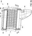
- Fig. 3a is a schematic perspective view of an embodiment of a disposable air filter unit 100 for filtering air intake to an internal combustion engine in a vehicle.
- the air filter unit 100 forms a cylindrical sleeve about a central axis (X) and extends axially between a first end 102 and a second end 103.
- the air filter unit 100 forming an outer sleeve surface 104 for receiving unfiltered air, and an inner sleeve surface 105 for output of filtered air, when the filter unit 100 is in use in an air cleaner arrangement such as for example the arrangement described with reference to Fig. 2 .
- the air filter unit 100 may be installed in an air cleaner housing 17 in an air intake system 10 as described in the above. However, it will be understood that the air filter unit 100 may be applied also in other air cleaner arrangements.
- Fig. 3b is a split view of the air filter unit 100 of Fig. 3a .
- the air filter unit 100 comprises a pleated filter component 100a and a bioplastic reinforcement structure 100b, arranged at the pleated filter component 100a.
- the pleated filter component 100a forms a cylindrical sleeve about said central axis (X) and extends axially between a first end surface 102a and a second end surface 103a.
- the pleated filter component 100a forms an outer sleeve surface 104a for receiving unfiltered air, and an inner sleeve surface 105a for output of filtered air.
- the pleats of the pleated filter component extend generally axially.
- the bioplastic reinforcement structure 100b comprises a first end surface 102b and a second end surface 103b.
- the end surfaces 102b, 103b are annular and adapted so as to cover the first end surface 102a and the second end surface 103a of the pleated filter component 100a.
- the end surfaces 102b, 103b of the bioplastic reinforcement structure are connected by an axially extending, sleeve-shaped cage 105b.
- the cage 105b is adapted to fit inside the inner sleeve surface 105a.
- the cage 105b is formed so as to allow air to pass through the filter unit 100 from the outer sleeve surface 104 to the inner sleeve surface 105.
- the end surface 102b, 103b of the bioplastic reinforcement structure are adapted so as to hinder air from escaping via the end surfaces 102, 103 of the filter unit 100.
- the bioplastic reinforcement structure 100b is made of a bioplastic material as defined in the above.
- the bioplastic reinforcement structure is a bioplastic from renewable biomass sources which is biodegradable, such as a PolyLacticAcid (PLA) material.
- PLA PolyLacticAcid
- the bioplastic reinforcement structure 100b may be directly adhered to the pleated filter component 100a, for example, end surfaces 102b, 103b may be directly moulded onto the end surfaces 102a, 103a of the pleated filter member 100a.
- the bioplastic reinforcement structure 100b may comprise one or more a separate component(s) attached to the filter component 100a.
- the bioplastic reinforcement structure 100b may be attached e.g. by an adhesive.
- the bioplastic reinforcement structure 100b may comprise at least one axially extending guiding means 108 along the inner sleeve surface 105 of the filter 100.
- the axially extending guiding means 108 may comprise an axially extending groove or ridge in the bioplastic reinforcement structure 100b.
- the axially extending groove or ridge may extend through the first end 102b, second end 103b, and the cage 105b of the bioplastic reinforcement structure 100b.
- a plurality of axially extending grooves 108 are arranged circumferentially about the inner circumference of the bioplastic reinforcement structure 100b.
- the axially extending guiding means 108 are to be adapted to fit with corresponding guiding means 208 in a carrier structure 200, which will be described later.
- the bioplastic reinforcement structure 100b may have a uniform thickness being between 2 mm and 20 mm, preferably between 4 and 15 mm.
- the outer sleeve surface 104 of the disposable filter unit 100 of Figs 3a , 3b may form an outer diameter of 200 - 400 mm, and an axial length between said first end 102 and said second end 103 may be 300 to 500 mm.
- the disposable filter unit 100 of Figs. 3a , 3b consists only of the pleated filter component 100a and said one or more bioplastic reinforcement structure 100b. Accordingly, the disposable filter unit 100 may be made only of renewable sources, and may optionally also be biodegradable. Accordingly, production and disposal of the filter unit 100 may be rendered more sustainable than with previous alternatives.
- Fig. 4a is a perspective view of an air cleaner assembly 300 for an air cleaner arrangement in a vehicle.
- the air cleaner arrangement 300 comprises a disposable air filter unit 100 and a reusable carrier structure 200 to which said air filter unit 100 is removably arranged.
- the disposable air filter unit 100 forms a sleeve about a central axis (X), extending axially between a first end surface 102 and a second end surface 103, and forms an outer sleeve surface 104 for receiving unfiltered air, and an inner sleeve surface 105 for output of filtered air.
- the air filter unit 100 may be an air filter unit as described in the above, for example an air filter unit 100 as described with reference to Figs 3a and 3a .
- the reusable carrier structure 200 comprises a receiving member 201 for receiving said first end surface 102 of the air filter unit 100, and a sealing member 204 arranged at the receiving member 201, to contact said first end surface 102 of the air filter unit 100.
- the air cleaner assembly 300 may be assembled by arranging an air filter unit 100 on the reusable carrier structure 200.
- the air cleaner assembly 300 may then in turn be arranged in an air cleaner housing in an air cleaner arrangement, as will be further described in the below.
- the reusable carrier structure 200 comprises an enclosure portion 206 adapted to form part of a filter enclosure of an air filter housing 400.
- the enclosure portion 206 forms a generally circular portion. This is convenient since the receiving member 201 will be generally annular in order to receive the first end 102 of the sleeve-shaped filter unit 100.
- the reusable carrier structure 200 comprises a sealing member 204 to seal against the first end surface 102 of the air filter unit 100.
- the sealing member 204 is an annular member extending at the receiving member 201 of the reusable carrier structure 200.
- the sealing member 204 may be an oring, for example arranged in a suitable groove.
- the reusable carrier structure 200 performs the function of carrying a filter unit 100 into or out from a housing of an air cleaner arrangement, and moreover provides the sealing at a first end of the filter unit 100.
- the reusable carrier structure 200 further comprises a support member 202 extending axially from said receiving member 201 to a free end 203.
- the support member 202 is adapted to be surrounded by the inner sleeve surface 105 of the air filter unit 100.
- the sealing member 204 extends annularly around said support member 202 so as to contact the first end portion 102 of the filter unit 100.
- the support member 202 comprises axially extending guiding means 208 for guiding said air filter unit 100 during attachment and removal thereof from the reusable carrier structure 200.
- the guiding means 208 comprises axially extending ridges corresponding to the axially extending grooves 108 of the filter unit 100.
- connection means 205 for connecting said free end 203 to an air filter housing 400.
- connection means 205 comprises a circular edge which is adapted to fit into a corresponding groove of the air filter housing 400.
- the axial length of the support member 202 from the receiving member to the free end 203 exceeds the axial length of the filter unit 100 between the first end surface 102 and the second end surface 103. In this case, this enables the connection means 205 at the free end of 203 of the support member 202 to extend from the second end 203 of the filter unit 100, when in an assembled condition ( Fig. 4a ).
- the axial length of the support member 202 from the receiving member 201 to the free end 203 is equal to or less than the axial length of the filter unit 100 between the first end surface 102 and the second end surface 103.
- the axial length of the support member 202 from the receiving member 201 to the free end 203 may correspond to at least 20% of the length between the first end surface 102 and the second end surface 103 of the filter unit 100, more preferred corresponding to at least 75% of the length between said first end surface and said second end surface of the filter unit 100.
- the corresponding filter housing 400 may instead be provided with a support member which extends so as to meet the support member 202 of the reusable carrier unit 200.
- the air cleaner assembly 300 may be adapted to a housing 400 without any support structure extending all the way axially through the filter unit 100.
- Figs. 4c and 4d illustrate an embodiment (which does not form part of the claimed invention) of an air cleaner assembly 300, wherein no support member 202 is present.
- the first end surface 102 of the air filter unit 100 is nevertheless received by the receiving member 201, and a sealing member 203 is arranged a the receiving member 201 to contact the first end surface 102 of the air filter unit 100.
- This is quite similar to what is described in the above with reference to Figs. 4a and 4b , and reference is made to the description of the first embodiment for applicable parts.
- the reusable carrier structure 200 performs the function of carrying a filter unit 100 into or out from a housing of an air cleaner arrangement, and moreover provides the sealing at a first end of the filter unit 100, in a similar manner as the first embodiment of Figs. 4a and 4b .
- the reusable carrier structure 200 regardless of embodiment, is provided as one single member, meaning that it may be handled as such in use.
- the single member per say may naturally be made out of one or more assembled pieces.
- the reusable carrier structure 200 may be made by any suitable reusable material, i.e. a material which withstands the stresses of continued use, for example a suitable plastic material.
- Fig. 6a illustrates an air cleaner arrangement 500 comprising a filter housing 400, and a reusable carrier structure 200 for carrying a disposable air filter unit 100.
- the air filter unit 100 is forming a sleeve about a central axis (X) and extending axially between a first end surface 102 and a second end surface 103 and defining an outer sleeve surface 104 for receiving unfiltered air, and an inner sleeve surface 105 for output of filtered air.
- the air cleaner arrangement 500 may be used with any such air filter unit 100, but is particularly advantageous when used with a disposable air filter unit 100 as described in the above.
- the reusable carrier structure 200 comprises a first receiving member 201 for receiving said first end 102 of the air filter unit 100, and a first sealing member 204 arranged at the receiving member 201, the first sealing member 204 being adapted to interact with said first end surface 102 of the air filter unit 100.
- the reusable carrier structure 200 may be as described in the above in relation to the air cleaner assembly 300. Indeed, when in use, the reusable carrier structure 200 will naturally carry a filter unit 100 so as to form such an air cleaner assembly 300. In the embodiment illustrated in Fig. 6 , the reusable carrier structure 200 is as described in relation to the embodiment of Figs. 4a and 4b in the above.
- Fig. 5a illustrates a variant of a filter housing 400.
- the filter housing 400 defines an air filter cavity 401 for receiving the air filter 100.
- the air filter cavity 403 has an inner wall 402 comprising a second receiving member 403 for receiving the second end surface 103 of the air filter unit 100, and a second sealing member 404 arranged at the second receiving member 403, the second sealing member 404 being adapted to interact with said second end surface 103 of the air filter unit 100.
- the air filter cavity 401 is adapted for axial introduction of the air filter 100.
- the filter housing 400 further defines a peripherally arranged air inlet 408, and an axially arranged air outlet 409. Via the air inlet 408 and outlet 409, the filter housing 400 and hence the air cleaner arrangement 500 may be arranged in an air inlet system such as the one described in relation to Fig. 2 .
- the second receiving member 403 and the second sealing member 404 is arranged to surround said air outlet 409.
- the second sealing member 404 is an annular member extending around the air outlet 409.
- the second sealing member 404 may be an oring, for example arranged in a suitable groove.
- an air cleaner arrangement 500 including a housing 400 as in Fig. 5a is illustrated.
- the air cleaner arrangement further comprises a reusable carrier structure 200.
- the reusable carrier structure 200 comprises an enclosure portion 206 adapted to complement the inner wall 402 of the filter cavity 401, so as to, when the reusable carrier structure 200 is arranged in the filter housing 400, join the inner wall 402 of the filter cavity 401, so as to form a closed air filter compartment.
- the enclosure portion 206 is generally circular, forming an axial end wall to be arranged at the generally circular opening to the filter cavity 401 of the filter housing 400.
- a disposable filter unit 100 may be axially clamped between said first receiving member 203 and said second receiving member 403, such that the first sealing member 204 sealingly contacts the first end surface 102 of the filter unit 100, and the second sealing member 404 sealingly contacts the second end surface 103 of the filter unit 100, when the air cleaner arrangement 500 is in a use condition, as illustrated in Fig. 6a .
- the reusable carrier structure 200 further comprises a support member 202 as described in relation to Figs. 4a and 4b .
- the support member 202 extends axially from said receiving member 201 to a free end portion 203, the support member 202 being adapted to be surrounded by said inner sleeve surface 105 of the air filter unit 100, and the sealing member 204 being arranged annularly around said support member 202.
- the inner wall 402 of the filter cavity 401 comprises a support member receiving element 405 adapted to receive the free end portion 203 of the support member 202 of the reusable carrier structure 200.
- Fig. 6b is similar to Fig. 6a , but illustrates an embodiment where the reusable carrier structure 200 is as described in relation to Figs. 4c and 4d .
- the reusable carrier structure 200 does not comprise any support member 202.
- the filter unit 100 alone extends axially from the first receiving member 203 to the second receiving member 204.
- the disposable filter unit 100 is attachable and removable by axial displacement of the reusable carrier structure 200 in relation to the filter housing 400, so as to enable replacement of the disposable filter unit 100.
- FIG. 7a This is described in relation to Figs. 7a to 7d .
- the method for replacing a disposable air filter unit 100 in an air cleaner arrangement 500 is illustrated with reference to the embodiments of Figs. 4a , 4b and 6a , but may be equally applied to the embodiment of Figs. 4c , 4d and 6b , or to other embodiments.
- a first step comprises axially removing the reusable support structure 200 carrying a used air filter unit 100 from the filter cavity 401 of the filter housing 400.
- a second step comprises axially removing the used air filter unit 100 from the reusable support structure 200.
- a third step comprises axially applying an air filter unit 100 to the reusable support structure 200.
- an air filter unit 100 As mentioned in the above, preferably the used air filter unit 100 of Figs 7a and 7b is discarded, and a new unused air filter unit 100 is applied to the reusable support structure 200 in the third step.
- a fourth step comprises axially introducing the reusable support structure 200 carrying the filter unit 100 into the filter cavity 201 of the filter housing 400.
- the support structure 200 may be locked to the filter housing 400 using the axial locking means 207, 407.
- steps 7b and 7c may be performed by a service technician at any location remote from the filter housing, meaning that an ergonomically suitable working position may be selected.
Description
- The invention relates to an air cleaner assembly for an air cleaner arrangement in a vehicle, comprising a disposable air filter unit and a reusable carrier structure to which said air filter unit is removably arranged. Moreover, the invention relates to a vehicle.
- The invention can be applied in heavy-duty vehicles, such as trucks, buses and construction equipment. Although the invention will be described with respect to a truck, the invention is not restricted to this particular vehicle, but may also be used in other vehicles such as buses and construction equipment.
- An internal combustion engine receives air to combust fuel in a combustion chamber to produce power. Such an engine is provided with an intake system in order to supply air from the outside of the vehicle to the internal combustion engine.
- The air intake system of a vehicle may include an air intake followed by an intake duct, for supplying air to an air cleaner arrangement. The air cleaner arrangement typically comprises an air cleaner housing in which an air filter is arranged, to filter the air from dust by passage through the air filter before reaching the internal combustion engine. Air cleaner arrangements and air filters may be designed in many different shapes and configurations. The most common solution in today's trucks is to use a cylindrical air cleaner with a cylindrical air filter.
- The air filter needs to be replaced on a regular basis (from e.g. every month to every second year) to keep the air cleaning function on a desired level. The replacement of the air filter is time consuming, and may often involve work being unergonomic for the service technician.
- The used air filters are disposed. Conventionally, the air filters consists of a pleated filter media that is shaped into a cylinder where the ends are casted together with a PUR (polyureathane) material to provide radial and axial seal, and which is further provided with a plastic inner cage to provide axial strength. Disposal of units is inefficient when it comes to sustainability, with wastes in production, transportation and disposal.
-
US 2014/0223868 discloses an air filter system having a housing and at least one detachable cover detachably connected to the housing to close off the housing. At least one exchangeable element is arranged within the housing. - As such, it would be desirable to facilitate the replacement of an air filter in an air cleaner arrangement. Also, it would be desirable to improve sustainability and/or economy for disposable air filters.
DE 20 2008 010504 U1 ,EP 0 562 502 A1 ,US 6 379 410 B1 ,EP 0 676 228 A1 ,GB 1 583 736 A EP 0 991 459 A1 ,US 2016/354716 A1 ,US 2007/113529 A1 ,EP 0 357 917 A1 andUS 7 168 573 B2 show further filter systems. - The invention relates to an air cleaner assembly for an air cleaner arrangement in a vehicle, comprising a disposable air filter unit and a reusable carrier structure to which said air filter unit is removably arranged. The disposable air filter unit forms a sleeve about a central axis (X), extending axially between a first end surface and a second end surface, and forms an outer sleeve surface for receiving unfiltered air, and an inner sleeve surface for output of filtered air. The reusable carrier structure comprises a receiving member for receiving said first end surface of the air filter unit, and a sealing member arranged at the receiving member, to contact said first end surface of the air filter unit. The reusable carrier structure comprises a support member extending axially from said receiving member to a free end, the support member being adapted to be surrounded by said inner sleeve surface of the air filter unit, wherein the air filter unit comprises a pleated filter component and a bioplastic reinforcement structure, arranged at the pleated filter component.
- The air cleaner assembly comprising a disposable air filter unit and a reusable carrier structure may be used for attaching and removing the disposable air filter unit to an air cleaner arrangement. The air cleaner assembly may be removable from the air cleaner arrangement, such that the disposable air filter unit may be removed from the reusable carrier structure and replaced by a new disposable air filter unit. Hence, more ergonomic working positions may be assumed.
- Accordingly, the receiving member may be adapted to realeasably lock said filter unit to said reusable carrier structure in an axial direction, for example by mechanical locking such as by press-fit or snap-lock.
- Optionally, the receiving member may be annular so as to receive the first end surface of the air filter unit.
- The reusable carrier structure comprises a receiving member for receiving a first end surface of the air filter unit. The sealing member being arranged at the receiving member, enables sealing contact with the first end surface of the air filter unit. Accordingly, the air filter unit per se may be devoid of sealing members, which diminishes the amount of material in the filter unit which is to be discarded.
- Optionally, the sealing member is an annular member, for example an oring.
- Optionally, the first sealing member may extend annularly around said support member.
- Optionally, the support member comprises axially extending guiding means for guiding said air filter unit during attachment and removal thereof from the reusable carrier structure.
- Optionally, the support member may be adapted to realeasably lock said filter unit to said reusable carrier structure in an axial direction, for example by mechanical locking such as by press-fit or snap-lock.
- Optionally, the free end of the support member comprises connecting means for connecting said free end to an air filter housing.
- Optionally, the reusable carrier structure comprises an enclosure portion adapted to form part of a filter enclosure of an air filter housing.
- Optionally, when the reusable carrier structure comprises a support member as described in the above, an axial length of the support member from the receiving member to the free end corresponds to at least 20% of the length between the first end surface and the second end surface of the filter unit, more preferred corresponding to at least 75% of the length between said first end surface and said second end surface of the filter unit, most preferred corresponding to at least the length between said first end surface and said second end surface of the filter unit.
- Optionally, the reusable carrier structure forms one single element when in use.
- In a second aspect, the invention relates to a vehicle comprising an air cleaner assembly as described in the above.
- It will be understood that features and advantages described herein with reference to any aspect of the invention may equally be applied to the other aspects of the invention.
- Further advantages and advantageous features of the invention are disclosed in the following description and in the dependent claims.
- With reference to the appended drawings, below follows a more detailed description of embodiments of the invention cited as examples.
- In the drawings:
-
Fig. 1 is a schematic view of a vehicle; -
Fig. 2 is a schematic view of an air intake system; -
Fig. 3a is a schematic perspective view of an embodiment of a disposable air filter unit; -
Fig. 3b is a schematic split view of the disposable air filter unit ofFig. 3a ; -
Fig. 4a is a schematic perspective view of a first embodiment of an air cleaner assembly; -
Fig. 4b is a split view of the air cleaner assembly ofFig. 4a ; -
Fig. 4c is a schematic perspective view of a second embodiment (which does not form part of the claimed invention) of an air cleaner assembly; -
Fig. 4d is a split view of the air cleaner assembly ofFig. 4c ; -
Figs 5a is a perspective view of an embodiment of afilter housing 400 for use in an embodiment of anair cleaner arrangement 500; -
Fig. 5b is a perspective view of an embodiment of anair cleaner arrangement 500; -
Fig. 6a is a cross-sectional view of an embodiment of anair cleaner arrangement 500 of -
Fig. 5b , comprising the housing ofFig. 5a , and the air cleaner assembly ofFigs 4a ,4b ; -
Fig. 6b is a cross-sectional view of an embodiment of anair cleaner arrangement 500 of -
Fig. 5b , comprising a housing and the air cleaner assembly ofFigs 4c ,4d ; and -
Figs. 7a to 7d illustrate an embodiment of a method for replacing a disposable air filter unit. - In
Figs 3a to 7d , like reference numbers refer to similar features. - The invention will be described below for a vehicle in the form of a truck 1 such as the truck illustrated in
Fig. 1 . The truck 1 should be seen as an example of a vehicle which could comprise an air supply arrangement according to the present invention and/or a separator as described herein. - However, the present invention may be implemented in a plurality of different types of vehicles. Purely by way of example, the present invention could be implemented in a truck, a tractor, a car, a bus, a work machine such as a wheel loader or an articulated hauler, or any other type of construction equipment.
- The
Fig. 1 vehicle 1 comprises anair intake system 10 as illustrated inFig. 2 . Anair intake system 10 is generally arranged so as to supply air from the outside of a vehicle, e.g. from the outside of the cab, to an internal combustion engine of the vehicle. - The
air intake system 10 ofFig. 2 will now be described as an example. However, it is to be understood that the present invention may be applied also in other variants of air intake systems. - The
air intake system 10 ofFig. 2 comprises anair intake 12 in connection with outside air. Theair intake 12 is in communication with anair duct 13 for transferring air further into the vehicle. The exemplifiedair duct 13 has an elongated shape which is arranged in a generally vertical direction (with respect to a vertical direction of the vehicle). Theair duct 13 leads the air to a bellow 14, which in turn is connected to aturn chamber 15. From theturn chamber 15 the air is fed further downstream to anair cleaner cleaner housing 17 and an aircleaner cover 16. Inside the aircleaner housing 17, an air filter is arranged (not visible inFig. 2 ). The aircleaner cover 16 is removable from the aircleaner housing 17 so as to enable replacement of the air filter when necessary. - The air
cleaner housing 17 is in connection with an aircleaner rubber bellow 18 which is in turn connected anintermediate pipe 19. Downstream theintermediate pipe 19, there is a turbo inlet, here in the form of a turboinlet rubber bellow 20. From the turbo inlet, the air will continue downstream towards the internal combustion engine (not shown inFig. 2 ). - It is to be understood that the illustrated
air intake system 10 is exemplary, and that the invention may be applied to numerous variants of air intake systems. - In the following, exemplary embodiments of the invention will be described with reference to
Figs. 3a to 7d . -
Fig. 3a is a schematic perspective view of an embodiment of a disposableair filter unit 100 for filtering air intake to an internal combustion engine in a vehicle. Theair filter unit 100 forms a cylindrical sleeve about a central axis (X) and extends axially between afirst end 102 and asecond end 103. Theair filter unit 100 forming anouter sleeve surface 104 for receiving unfiltered air, and aninner sleeve surface 105 for output of filtered air, when thefilter unit 100 is in use in an air cleaner arrangement such as for example the arrangement described with reference toFig. 2 . Hence, theair filter unit 100 may be installed in an aircleaner housing 17 in anair intake system 10 as described in the above. However, it will be understood that theair filter unit 100 may be applied also in other air cleaner arrangements. -
Fig. 3b is a split view of theair filter unit 100 ofFig. 3a . In the illustrated embodiment, theair filter unit 100 comprises apleated filter component 100a and abioplastic reinforcement structure 100b, arranged at thepleated filter component 100a. - The
pleated filter component 100a forms a cylindrical sleeve about said central axis (X) and extends axially between afirst end surface 102a and asecond end surface 103a. Thepleated filter component 100a forms anouter sleeve surface 104a for receiving unfiltered air, and aninner sleeve surface 105a for output of filtered air. The pleats of the pleated filter component extend generally axially. - In the illustrated embodiment, the
bioplastic reinforcement structure 100b comprises afirst end surface 102b and asecond end surface 103b. The end surfaces 102b, 103b are annular and adapted so as to cover thefirst end surface 102a and thesecond end surface 103a of thepleated filter component 100a. The end surfaces 102b, 103b of the bioplastic reinforcement structure are connected by an axially extending, sleeve-shapedcage 105b. Thecage 105b is adapted to fit inside theinner sleeve surface 105a. - The
cage 105b is formed so as to allow air to pass through thefilter unit 100 from theouter sleeve surface 104 to theinner sleeve surface 105. In contrast, theend surface filter unit 100. - It will be understood that numerous variants of the shape of the
bioplastic reinforcement structure 100b are possible. - The
bioplastic reinforcement structure 100b is made of a bioplastic material as defined in the above. In particular, in a preferred embodiment, the bioplastic reinforcement structure is a bioplastic from renewable biomass sources which is biodegradable, such as a PolyLacticAcid (PLA) material. - As mentioned in the above, the
bioplastic reinforcement structure 100b may be directly adhered to thepleated filter component 100a, for example, end surfaces 102b, 103b may be directly moulded onto theend surfaces pleated filter member 100a. - Optionally, the
bioplastic reinforcement structure 100b may comprise one or more a separate component(s) attached to thefilter component 100a. Thebioplastic reinforcement structure 100b may be attached e.g. by an adhesive. - The
bioplastic reinforcement structure 100b may comprise at least one axially extending guiding means 108 along theinner sleeve surface 105 of thefilter 100. As in the illustrated embodiment, the axially extending guiding means 108 may comprise an axially extending groove or ridge in thebioplastic reinforcement structure 100b. The axially extending groove or ridge may extend through thefirst end 102b,second end 103b, and thecage 105b of thebioplastic reinforcement structure 100b. In the illustrated embodiment, a plurality of axially extendinggrooves 108 are arranged circumferentially about the inner circumference of thebioplastic reinforcement structure 100b. - The axially extending guiding means 108 are to be adapted to fit with corresponding guiding means 208 in a
carrier structure 200, which will be described later. - The
bioplastic reinforcement structure 100b may have a uniform thickness being between 2 mm and 20 mm, preferably between 4 and 15 mm. - For example, the
outer sleeve surface 104 of thedisposable filter unit 100 ofFigs 3a ,3b may form an outer diameter of 200 - 400 mm, and an axial length between saidfirst end 102 and saidsecond end 103 may be 300 to 500 mm. - The
disposable filter unit 100 ofFigs. 3a ,3b consists only of thepleated filter component 100a and said one or morebioplastic reinforcement structure 100b. Accordingly, thedisposable filter unit 100 may be made only of renewable sources, and may optionally also be biodegradable. Accordingly, production and disposal of thefilter unit 100 may be rendered more sustainable than with previous alternatives. -
Fig. 4a is a perspective view of an aircleaner assembly 300 for an air cleaner arrangement in a vehicle. Theair cleaner arrangement 300 comprises a disposableair filter unit 100 and areusable carrier structure 200 to which saidair filter unit 100 is removably arranged. The disposableair filter unit 100 forms a sleeve about a central axis (X), extending axially between afirst end surface 102 and asecond end surface 103, and forms anouter sleeve surface 104 for receiving unfiltered air, and aninner sleeve surface 105 for output of filtered air. Theair filter unit 100 may be an air filter unit as described in the above, for example anair filter unit 100 as described with reference toFigs 3a and 3a . - As best seen in
Fig. 4b , which is a the split view of theair cleaner assembly 300 ofFig. 4a , thereusable carrier structure 200 comprises a receivingmember 201 for receiving saidfirst end surface 102 of theair filter unit 100, and a sealingmember 204 arranged at the receivingmember 201, to contact saidfirst end surface 102 of theair filter unit 100. - It will be understood that the
air cleaner assembly 300 may be assembled by arranging anair filter unit 100 on thereusable carrier structure 200. Theair cleaner assembly 300 may then in turn be arranged in an air cleaner housing in an air cleaner arrangement, as will be further described in the below. Thereusable carrier structure 200 comprises anenclosure portion 206 adapted to form part of a filter enclosure of anair filter housing 400. In the illustrated embodiment, theenclosure portion 206 forms a generally circular portion. This is convenient since the receivingmember 201 will be generally annular in order to receive thefirst end 102 of the sleeve-shapedfilter unit 100. - Further, the
reusable carrier structure 200 comprises a sealingmember 204 to seal against thefirst end surface 102 of theair filter unit 100. The sealingmember 204 is an annular member extending at the receivingmember 201 of thereusable carrier structure 200. Advantageously, the sealingmember 204 may be an oring, for example arranged in a suitable groove. - Hence, the
reusable carrier structure 200 performs the function of carrying afilter unit 100 into or out from a housing of an air cleaner arrangement, and moreover provides the sealing at a first end of thefilter unit 100. - In the embodiment illustrated in
Figs 4a and4b , thereusable carrier structure 200 further comprises asupport member 202 extending axially from said receivingmember 201 to afree end 203. Thesupport member 202 is adapted to be surrounded by theinner sleeve surface 105 of theair filter unit 100. As seen inFig. 4b , the sealingmember 204 extends annularly around saidsupport member 202 so as to contact thefirst end portion 102 of thefilter unit 100. - In the illustrated embodiment the
support member 202 comprises axially extending guiding means 208 for guiding saidair filter unit 100 during attachment and removal thereof from thereusable carrier structure 200. Here, the guiding means 208 comprises axially extending ridges corresponding to theaxially extending grooves 108 of thefilter unit 100. - Further, the
free end 203 of thesupport member 202 comprises connecting means 205 for connecting saidfree end 203 to anair filter housing 400. In the illustrated embodiment, the connection means 205 comprises a circular edge which is adapted to fit into a corresponding groove of theair filter housing 400. - In the illustrated embodiment, the axial length of the
support member 202 from the receiving member to thefree end 203 exceeds the axial length of thefilter unit 100 between thefirst end surface 102 and thesecond end surface 103. In this case, this enables the connection means 205 at the free end of 203 of thesupport member 202 to extend from thesecond end 203 of thefilter unit 100, when in an assembled condition (Fig. 4a ). - Other embodiments may be envisaged, wherein the axial length of the
support member 202 from the receivingmember 201 to thefree end 203 is equal to or less than the axial length of thefilter unit 100 between thefirst end surface 102 and thesecond end surface 103. For example, the axial length of thesupport member 202 from the receivingmember 201 to thefree end 203 may correspond to at least 20% of the length between thefirst end surface 102 and thesecond end surface 103 of thefilter unit 100, more preferred corresponding to at least 75% of the length between said first end surface and said second end surface of thefilter unit 100. - When the axial length of the
support member 202 is less than the axial length of thefilter unit 100, thecorresponding filter housing 400 may instead be provided with a support member which extends so as to meet thesupport member 202 of thereusable carrier unit 200. - This is however not necessary. Instead, as will be described in the below, the
air cleaner assembly 300 may be adapted to ahousing 400 without any support structure extending all the way axially through thefilter unit 100. -
Figs. 4c and4d illustrate an embodiment (which does not form part of the claimed invention) of an aircleaner assembly 300, wherein nosupport member 202 is present. Thefirst end surface 102 of theair filter unit 100 is nevertheless received by the receivingmember 201, and a sealingmember 203 is arranged a the receivingmember 201 to contact thefirst end surface 102 of theair filter unit 100. This is quite similar to what is described in the above with reference toFigs. 4a and4b , and reference is made to the description of the first embodiment for applicable parts. - Hence, in the second embodiment of
Figs. 4c and4d , thereusable carrier structure 200 performs the function of carrying afilter unit 100 into or out from a housing of an air cleaner arrangement, and moreover provides the sealing at a first end of thefilter unit 100, in a similar manner as the first embodiment ofFigs. 4a and4b . - The
reusable carrier structure 200, regardless of embodiment, is provided as one single member, meaning that it may be handled as such in use. The single member per say may naturally be made out of one or more assembled pieces. - The
reusable carrier structure 200 may be made by any suitable reusable material, i.e. a material which withstands the stresses of continued use, for example a suitable plastic material. -
Fig. 6a illustrates anair cleaner arrangement 500 comprising afilter housing 400, and areusable carrier structure 200 for carrying a disposableair filter unit 100. - The
air filter unit 100 is forming a sleeve about a central axis (X) and extending axially between afirst end surface 102 and asecond end surface 103 and defining anouter sleeve surface 104 for receiving unfiltered air, and aninner sleeve surface 105 for output of filtered air. Theair cleaner arrangement 500 may be used with any suchair filter unit 100, but is particularly advantageous when used with a disposableair filter unit 100 as described in the above. - The
reusable carrier structure 200 comprises a first receivingmember 201 for receiving saidfirst end 102 of theair filter unit 100, and afirst sealing member 204 arranged at the receivingmember 201, thefirst sealing member 204 being adapted to interact with saidfirst end surface 102 of theair filter unit 100. Hence, thereusable carrier structure 200 may be as described in the above in relation to theair cleaner assembly 300. Indeed, when in use, thereusable carrier structure 200 will naturally carry afilter unit 100 so as to form such an aircleaner assembly 300. In the embodiment illustrated inFig. 6 , thereusable carrier structure 200 is as described in relation to the embodiment ofFigs. 4a and4b in the above. -
Fig. 5a illustrates a variant of afilter housing 400. Thefilter housing 400 defines anair filter cavity 401 for receiving theair filter 100. Theair filter cavity 403 has aninner wall 402 comprising asecond receiving member 403 for receiving thesecond end surface 103 of theair filter unit 100, and asecond sealing member 404 arranged at the second receivingmember 403, thesecond sealing member 404 being adapted to interact with saidsecond end surface 103 of theair filter unit 100. In the illustrated embodiment, theair filter cavity 401 is adapted for axial introduction of theair filter 100. - The
filter housing 400 further defines a peripherally arrangedair inlet 408, and an axially arrangedair outlet 409. Via theair inlet 408 andoutlet 409, thefilter housing 400 and hence theair cleaner arrangement 500 may be arranged in an air inlet system such as the one described in relation toFig. 2 . - As seen in
Fig. 5a andFig. 6a , the second receivingmember 403 and thesecond sealing member 404 is arranged to surround saidair outlet 409. - The
second sealing member 404 is an annular member extending around theair outlet 409. Advantageously, thesecond sealing member 404 may be an oring, for example arranged in a suitable groove. - In
Fig. 5b andFig. 6a , anair cleaner arrangement 500 including ahousing 400 as inFig. 5a is illustrated. The air cleaner arrangement further comprises areusable carrier structure 200. - As described in the above, the
reusable carrier structure 200 comprises anenclosure portion 206 adapted to complement theinner wall 402 of thefilter cavity 401, so as to, when thereusable carrier structure 200 is arranged in thefilter housing 400, join theinner wall 402 of thefilter cavity 401, so as to form a closed air filter compartment. In the illustrated embodiments, theenclosure portion 206 is generally circular, forming an axial end wall to be arranged at the generally circular opening to thefilter cavity 401 of thefilter housing 400. - The
reusable carrier structure 200 and thefilter housing 400 each compriseaxial locking elements reusable carrier structure 200 to thefilter housing 400. In the illustrated embodiment, theaxial locking element 207 of thereusable carrier structure 200 comprises a loop, and theaxial locking element 407 of the housing comprises a snap-down element for engaging said loop. Naturally, the loop and snap-down element could be otherwise arranged, or any other suitable axial locking elements may be used. - In an air cleaner arrangement as described in the above, a
disposable filter unit 100 may be axially clamped between said first receivingmember 203 and said second receivingmember 403, such that thefirst sealing member 204 sealingly contacts thefirst end surface 102 of thefilter unit 100, and thesecond sealing member 404 sealingly contacts thesecond end surface 103 of thefilter unit 100, when theair cleaner arrangement 500 is in a use condition, as illustrated inFig. 6a . - In the embodiment of
Fig. 6a , thereusable carrier structure 200 further comprises asupport member 202 as described in relation toFigs. 4a and4b . Thesupport member 202 extends axially from said receivingmember 201 to afree end portion 203, thesupport member 202 being adapted to be surrounded by saidinner sleeve surface 105 of theair filter unit 100, and the sealingmember 204 being arranged annularly around saidsupport member 202. - Correspondingly, the
inner wall 402 of thefilter cavity 401 comprises a supportmember receiving element 405 adapted to receive thefree end portion 203 of thesupport member 202 of thereusable carrier structure 200. -
Fig. 6b is similar toFig. 6a , but illustrates an embodiment where thereusable carrier structure 200 is as described in relation toFigs. 4c and4d . Hence, thereusable carrier structure 200 does not comprise anysupport member 202. Instead, thefilter unit 100 alone extends axially from the first receivingmember 203 to the second receivingmember 204. - In both embodiments 6a and 6b, the
disposable filter unit 100 is attachable and removable by axial displacement of thereusable carrier structure 200 in relation to thefilter housing 400, so as to enable replacement of thedisposable filter unit 100. - This is described in relation to
Figs. 7a to 7d . The method for replacing a disposableair filter unit 100 in anair cleaner arrangement 500 is illustrated with reference to the embodiments ofFigs. 4a ,4b and6a , but may be equally applied to the embodiment ofFigs. 4c ,4d and6b , or to other embodiments. - In
Fig. 7a , a first step comprises axially removing thereusable support structure 200 carrying a usedair filter unit 100 from thefilter cavity 401 of thefilter housing 400. - In
Fig. 7b , a second step comprises axially removing the usedair filter unit 100 from thereusable support structure 200. - In
Fig. 7c , a third step comprises axially applying anair filter unit 100 to thereusable support structure 200. As mentioned in the above, preferably the usedair filter unit 100 ofFigs 7a and7b is discarded, and a new unusedair filter unit 100 is applied to thereusable support structure 200 in the third step. - In
Fig. 7d , a fourth step comprises axially introducing thereusable support structure 200 carrying thefilter unit 100 into thefilter cavity 201 of thefilter housing 400. - Once in place, the
support structure 200 may be locked to thefilter housing 400 using the axial locking means 207, 407. - Hence, steps 7b and 7c may be performed by a service technician at any location remote from the filter housing, meaning that an ergonomically suitable working position may be selected.
Claims (7)
- An air cleaner assembly (300) for an air cleaner arrangement in a vehicle, comprising a disposable air filter unit (100) and a reusable carrier structure (200) to which said air filter unit (100) is removably arranged, the disposable air filter unit (100) forming a sleeve about a central axis (X), extending axially between a first end surface (102) and a second end surface (103), and forming an outer sleeve surface (104) for receiving unfiltered air, and an inner sleeve surface (105) for output of filtered air,characterised by the reusable carrier structure (200)comprising a receiving member (201) for receiving said first end surface (102) of the air filter unit (100), anda sealing member (204) arranged at the receiving member (201), to contact said first end surface (102) of the air filter unit (100),wherein the reusable carrier structure (200) comprises a support member (202) extending axially from said receiving member (201) to a free end (203), the support member being adapted to be surrounded by said inner sleeve surface (105) of the air filter unit (100),wherein the air filter unit (100) comprises a pleated filter component (100a) and a bioplastic reinforcement structure (100b), arranged at the pleated filter component (100a).
- An air cleaner assembly according to claim 1, wherein said sealing member (204) extends annularly around said support member (202).
- An air cleaner assembly (300) according to claim 1 or 2, wherein said support member (202) comprises axially extending guiding means (208) for guiding said air filter unit (100) during attachment and removal thereof from the reusable carrier structure.
- An air cleaner assembly (300) according to any one of claims 1 to 3 wherein said free end (203) of the support member (202) comprises connecting means (205) for connecting said free end (203) to an air filter housing (400).
- An air cleaner assembly (300) according to any one of the claims 1 to 4, wherein said reusable carrier structure (200) comprises an enclosure portion (206) adapted to form part of a filter enclosure of an air filter housing (400).
- An air cleaner assembly (300) according to any one of the claims 1 to 4, wherein an axial length of the support member (202) from the receiving member (201) to the free end (203) corresponds to at least 20% of the length between the first end surface (102) and the second end surface (103) of the filter unit (100), more preferred corresponding to at least 75% of the length between said first end surface (102) and said second end surface (103) of the filter unit (100), most preferred corresponding to at least the length between said first end surface (102) and said second end surface (103) of the filter unit (100).
- A vehicle comprising an air cleaner assembly according to any one of the claims 1 to 6.
Applications Claiming Priority (1)
| Application Number | Priority Date | Filing Date | Title |
|---|---|---|---|
| PCT/EP2018/065385 WO2019238212A1 (en) | 2018-06-11 | 2018-06-11 | A disposable air filter unit, an air cleaner assembly and an air cleaner arrangement |
Publications (2)
| Publication Number | Publication Date |
|---|---|
| EP3801820A1 EP3801820A1 (en) | 2021-04-14 |
| EP3801820B1 true EP3801820B1 (en) | 2022-08-03 |
Family
ID=62684765
Family Applications (1)
| Application Number | Title | Priority Date | Filing Date |
|---|---|---|---|
| EP18732698.8A Active EP3801820B1 (en) | 2018-06-11 | 2018-06-11 | A disposable air filter unit, an air cleaner assembly and an air cleaner arrangement |
Country Status (3)
| Country | Link |
|---|---|
| EP (1) | EP3801820B1 (en) |
| CN (1) | CN112512662B (en) |
| WO (1) | WO2019238212A1 (en) |
Families Citing this family (2)
| Publication number | Priority date | Publication date | Assignee | Title |
|---|---|---|---|---|
| EP4106902B1 (en) * | 2020-02-21 | 2024-03-27 | Volvo Truck Corporation | An air filter element |
| WO2021234535A1 (en) * | 2020-05-17 | 2021-11-25 | Rai Gaurav | Disposable air filter for vehicles |
Family Cites Families (16)
| Publication number | Priority date | Publication date | Assignee | Title |
|---|---|---|---|---|
| CA1099220A (en) * | 1977-06-06 | 1981-04-14 | Kenneth A. Conti | Air cleaner with permanent cartridge seal |
| DE3826246A1 (en) * | 1988-08-02 | 1990-02-15 | Kessler & Luch Gmbh | PROTECTIVE FILTER |
| DE9204169U1 (en) * | 1992-03-27 | 1992-06-11 | Rapp, Peter, 7114 Pfedelbach, De | |
| AU7307294A (en) * | 1994-04-05 | 1995-10-12 | G.U.D. Filters (Atlantis) (Proprietary) Limited | Air filter |
| US5938804A (en) * | 1994-11-23 | 1999-08-17 | Donaldson Company, Inc. | Reverse flow air filter arrangement and method |
| US6379410B1 (en) * | 2000-05-19 | 2002-04-30 | Vortox Company | Air filter assembly for motor vehicles |
| US7168573B2 (en) * | 2002-06-07 | 2007-01-30 | Baldwin Filters, Inc. | Environmentally friendly filter cartridge |
| US6959819B2 (en) * | 2002-10-08 | 2005-11-01 | Pti Technologies, Inc. | Fatigue rated glass filled plastic filter assembly incorporating a coreless plastic filter element with integral seal |
| US7374595B2 (en) * | 2005-11-23 | 2008-05-20 | Emerson Electric Co. | Filter and system for improved sealing on a vacuum cleaner |
| CN101472654B (en) * | 2006-06-20 | 2015-06-10 | 卡明斯过滤Ip有限公司 | Replaceable filter elements including plural filter media and related filtration systems, tecniques and methods |
| EP2086663B2 (en) * | 2006-10-06 | 2018-04-11 | Donaldson Company, Inc. | Air cleaner |
| DE202008010504U1 (en) * | 2008-08-07 | 2009-12-17 | Mann+Hummel Gmbh | Filter system for filtering fluids |
| DE102014000927A1 (en) | 2013-02-12 | 2014-08-14 | Mann + Hummel Gmbh | filter element |
| DE102014016167A1 (en) * | 2014-11-04 | 2016-05-04 | Mann + Hummel Gmbh | Filter element and method for producing the same |
| JP2017001008A (en) * | 2015-06-05 | 2017-01-05 | 現代自動車株式会社Hyundai Motor Company | Filter paper separation type cylindrical filter and cylindrical air cleaner of applying the same |
| JP2018091174A (en) * | 2016-11-30 | 2018-06-14 | トヨタ紡織株式会社 | Cylindrical air cleaner and cylindrical filter element for internal combustion engine |
-
2018
- 2018-06-11 CN CN201880094389.7A patent/CN112512662B/en active Active
- 2018-06-11 WO PCT/EP2018/065385 patent/WO2019238212A1/en active Search and Examination
- 2018-06-11 EP EP18732698.8A patent/EP3801820B1/en active Active
Also Published As
| Publication number | Publication date |
|---|---|
| WO2019238212A1 (en) | 2019-12-19 |
| CN112512662A (en) | 2021-03-16 |
| CN112512662B (en) | 2022-09-30 |
| EP3801820A1 (en) | 2021-04-14 |
| US20210260515A1 (en) | 2021-08-26 |
Similar Documents
| Publication | Publication Date | Title |
|---|---|---|
| US10138852B2 (en) | Air filter element | |
| US5064458A (en) | Heavy duty air filter with multipurpose end seal | |
| US7267706B2 (en) | Air filter | |
| US7662216B1 (en) | In-line filter and service method | |
| EP3801820B1 (en) | A disposable air filter unit, an air cleaner assembly and an air cleaner arrangement | |
| US20170036155A1 (en) | Air filter system and air filter element for an air filter system | |
| CN107438473B (en) | Secondary element for a filter system and filter system having a secondary element | |
| EP0933115B1 (en) | Self contained heavy-duty air filter | |
| EP1126159A2 (en) | Key system for ecological filter cartridge and element | |
| WO2017108835A1 (en) | Air filter system, filtering element of an air filter of an engine and supporting internal structure for a filtering element of an air filter of an engine | |
| CN112118899B (en) | Fluid filter with lightweight construction secondary filter element | |
| US11969685B2 (en) | Disposable air filter unit, an air cleaner assembly and an air cleaner arrangement | |
| CN112739443B (en) | Air filter housing for an air filter device in a vehicle | |
| CN107559110B (en) | air filter | |
| EP3801824B1 (en) | A replaceable air filter unit and an air filter arrangement | |
| EP4223383A1 (en) | Filter system having a primary and a secondary filter element and secondary filter element for such a filter system | |
| EP4223384A1 (en) | Filter system having a primary and a secondary filter element and secondary filter element and primary filter element for such a filter system | |
| EP1106819A2 (en) | Filter for pressure regulator | |
| US20240042362A1 (en) | Secondary Element and Filter System | |
| NZ239066A (en) | Heavy duty air filter for i.c. engine; seal at outlet adaptor seats primary and secondary elements |
Legal Events
| Date | Code | Title | Description |
|---|---|---|---|
| STAA | Information on the status of an ep patent application or granted ep patent |
Free format text: STATUS: UNKNOWN |
|
| STAA | Information on the status of an ep patent application or granted ep patent |
Free format text: STATUS: THE INTERNATIONAL PUBLICATION HAS BEEN MADE |
|
| STAA | Information on the status of an ep patent application or granted ep patent |
Free format text: STATUS: THE INTERNATIONAL PUBLICATION HAS BEEN MADE |
|
| PUAI | Public reference made under article 153(3) epc to a published international application that has entered the european phase |
Free format text: ORIGINAL CODE: 0009012 |
|
| STAA | Information on the status of an ep patent application or granted ep patent |
Free format text: STATUS: REQUEST FOR EXAMINATION WAS MADE |
|
| 17P | Request for examination filed |
Effective date: 20201217 |
|
| AK | Designated contracting states |
Kind code of ref document: A1 Designated state(s): AL AT BE BG CH CY CZ DE DK EE ES FI FR GB GR HR HU IE IS IT LI LT LU LV MC MK MT NL NO PL PT RO RS SE SI SK SM TR |
|
| AX | Request for extension of the european patent |
Extension state: BA ME |
|
| DAV | Request for validation of the european patent (deleted) | ||
| DAX | Request for extension of the european patent (deleted) | ||
| GRAP | Despatch of communication of intention to grant a patent |
Free format text: ORIGINAL CODE: EPIDOSNIGR1 |
|
| STAA | Information on the status of an ep patent application or granted ep patent |
Free format text: STATUS: GRANT OF PATENT IS INTENDED |
|
| INTG | Intention to grant announced |
Effective date: 20220221 |
|
| GRAS | Grant fee paid |
Free format text: ORIGINAL CODE: EPIDOSNIGR3 |
|
| GRAA | (expected) grant |
Free format text: ORIGINAL CODE: 0009210 |
|
| STAA | Information on the status of an ep patent application or granted ep patent |
Free format text: STATUS: THE PATENT HAS BEEN GRANTED |
|
| AK | Designated contracting states |
Kind code of ref document: B1 Designated state(s): AL AT BE BG CH CY CZ DE DK EE ES FI FR GB GR HR HU IE IS IT LI LT LU LV MC MK MT NL NO PL PT RO RS SE SI SK SM TR |
|
| REG | Reference to a national code |
Ref country code: AT Ref legal event code: REF Ref document number: 1508290 Country of ref document: AT Kind code of ref document: T Effective date: 20220815 Ref country code: CH Ref legal event code: EP |
|
| REG | Reference to a national code |
Ref country code: DE Ref legal event code: R096 Ref document number: 602018038758 Country of ref document: DE |
|
| REG | Reference to a national code |
Ref country code: IE Ref legal event code: FG4D |
|
| REG | Reference to a national code |
Ref country code: SE Ref legal event code: TRGR |
|
| REG | Reference to a national code |
Ref country code: LT Ref legal event code: MG9D |
|
| REG | Reference to a national code |
Ref country code: NL Ref legal event code: MP Effective date: 20220803 |
|
| PG25 | Lapsed in a contracting state [announced via postgrant information from national office to epo] |
Ref country code: RS Free format text: LAPSE BECAUSE OF FAILURE TO SUBMIT A TRANSLATION OF THE DESCRIPTION OR TO PAY THE FEE WITHIN THE PRESCRIBED TIME-LIMIT Effective date: 20220803 Ref country code: PT Free format text: LAPSE BECAUSE OF FAILURE TO SUBMIT A TRANSLATION OF THE DESCRIPTION OR TO PAY THE FEE WITHIN THE PRESCRIBED TIME-LIMIT Effective date: 20221205 Ref country code: NO Free format text: LAPSE BECAUSE OF FAILURE TO SUBMIT A TRANSLATION OF THE DESCRIPTION OR TO PAY THE FEE WITHIN THE PRESCRIBED TIME-LIMIT Effective date: 20221103 Ref country code: NL Free format text: LAPSE BECAUSE OF FAILURE TO SUBMIT A TRANSLATION OF THE DESCRIPTION OR TO PAY THE FEE WITHIN THE PRESCRIBED TIME-LIMIT Effective date: 20220803 Ref country code: LV Free format text: LAPSE BECAUSE OF FAILURE TO SUBMIT A TRANSLATION OF THE DESCRIPTION OR TO PAY THE FEE WITHIN THE PRESCRIBED TIME-LIMIT Effective date: 20220803 Ref country code: LT Free format text: LAPSE BECAUSE OF FAILURE TO SUBMIT A TRANSLATION OF THE DESCRIPTION OR TO PAY THE FEE WITHIN THE PRESCRIBED TIME-LIMIT Effective date: 20220803 Ref country code: FI Free format text: LAPSE BECAUSE OF FAILURE TO SUBMIT A TRANSLATION OF THE DESCRIPTION OR TO PAY THE FEE WITHIN THE PRESCRIBED TIME-LIMIT Effective date: 20220803 Ref country code: ES Free format text: LAPSE BECAUSE OF FAILURE TO SUBMIT A TRANSLATION OF THE DESCRIPTION OR TO PAY THE FEE WITHIN THE PRESCRIBED TIME-LIMIT Effective date: 20220803 |
|
| REG | Reference to a national code |
Ref country code: AT Ref legal event code: MK05 Ref document number: 1508290 Country of ref document: AT Kind code of ref document: T Effective date: 20220803 |
|
| PG25 | Lapsed in a contracting state [announced via postgrant information from national office to epo] |
Ref country code: PL Free format text: LAPSE BECAUSE OF FAILURE TO SUBMIT A TRANSLATION OF THE DESCRIPTION OR TO PAY THE FEE WITHIN THE PRESCRIBED TIME-LIMIT Effective date: 20220803 Ref country code: IS Free format text: LAPSE BECAUSE OF FAILURE TO SUBMIT A TRANSLATION OF THE DESCRIPTION OR TO PAY THE FEE WITHIN THE PRESCRIBED TIME-LIMIT Effective date: 20221203 Ref country code: HR Free format text: LAPSE BECAUSE OF FAILURE TO SUBMIT A TRANSLATION OF THE DESCRIPTION OR TO PAY THE FEE WITHIN THE PRESCRIBED TIME-LIMIT Effective date: 20220803 Ref country code: GR Free format text: LAPSE BECAUSE OF FAILURE TO SUBMIT A TRANSLATION OF THE DESCRIPTION OR TO PAY THE FEE WITHIN THE PRESCRIBED TIME-LIMIT Effective date: 20221104 |
|
| PG25 | Lapsed in a contracting state [announced via postgrant information from national office to epo] |
Ref country code: SM Free format text: LAPSE BECAUSE OF FAILURE TO SUBMIT A TRANSLATION OF THE DESCRIPTION OR TO PAY THE FEE WITHIN THE PRESCRIBED TIME-LIMIT Effective date: 20220803 Ref country code: RO Free format text: LAPSE BECAUSE OF FAILURE TO SUBMIT A TRANSLATION OF THE DESCRIPTION OR TO PAY THE FEE WITHIN THE PRESCRIBED TIME-LIMIT Effective date: 20220803 Ref country code: DK Free format text: LAPSE BECAUSE OF FAILURE TO SUBMIT A TRANSLATION OF THE DESCRIPTION OR TO PAY THE FEE WITHIN THE PRESCRIBED TIME-LIMIT Effective date: 20220803 Ref country code: CZ Free format text: LAPSE BECAUSE OF FAILURE TO SUBMIT A TRANSLATION OF THE DESCRIPTION OR TO PAY THE FEE WITHIN THE PRESCRIBED TIME-LIMIT Effective date: 20220803 Ref country code: AT Free format text: LAPSE BECAUSE OF FAILURE TO SUBMIT A TRANSLATION OF THE DESCRIPTION OR TO PAY THE FEE WITHIN THE PRESCRIBED TIME-LIMIT Effective date: 20220803 |
|
| REG | Reference to a national code |
Ref country code: DE Ref legal event code: R097 Ref document number: 602018038758 Country of ref document: DE |
|
| PG25 | Lapsed in a contracting state [announced via postgrant information from national office to epo] |
Ref country code: SK Free format text: LAPSE BECAUSE OF FAILURE TO SUBMIT A TRANSLATION OF THE DESCRIPTION OR TO PAY THE FEE WITHIN THE PRESCRIBED TIME-LIMIT Effective date: 20220803 Ref country code: EE Free format text: LAPSE BECAUSE OF FAILURE TO SUBMIT A TRANSLATION OF THE DESCRIPTION OR TO PAY THE FEE WITHIN THE PRESCRIBED TIME-LIMIT Effective date: 20220803 |
|
| PLBE | No opposition filed within time limit |
Free format text: ORIGINAL CODE: 0009261 |
|
| STAA | Information on the status of an ep patent application or granted ep patent |
Free format text: STATUS: NO OPPOSITION FILED WITHIN TIME LIMIT |
|
| PG25 | Lapsed in a contracting state [announced via postgrant information from national office to epo] |
Ref country code: AL Free format text: LAPSE BECAUSE OF FAILURE TO SUBMIT A TRANSLATION OF THE DESCRIPTION OR TO PAY THE FEE WITHIN THE PRESCRIBED TIME-LIMIT Effective date: 20220803 |
|
| 26N | No opposition filed |
Effective date: 20230504 |
|
| PGFP | Annual fee paid to national office [announced via postgrant information from national office to epo] |
Ref country code: FR Payment date: 20230622 Year of fee payment: 6 Ref country code: DE Payment date: 20230627 Year of fee payment: 6 |
|
| PG25 | Lapsed in a contracting state [announced via postgrant information from national office to epo] |
Ref country code: SI Free format text: LAPSE BECAUSE OF FAILURE TO SUBMIT A TRANSLATION OF THE DESCRIPTION OR TO PAY THE FEE WITHIN THE PRESCRIBED TIME-LIMIT Effective date: 20220803 |
|
| PGFP | Annual fee paid to national office [announced via postgrant information from national office to epo] |
Ref country code: SE Payment date: 20230626 Year of fee payment: 6 |
|
| PG25 | Lapsed in a contracting state [announced via postgrant information from national office to epo] |
Ref country code: MC Free format text: LAPSE BECAUSE OF FAILURE TO SUBMIT A TRANSLATION OF THE DESCRIPTION OR TO PAY THE FEE WITHIN THE PRESCRIBED TIME-LIMIT Effective date: 20220803 |
|
| PG25 | Lapsed in a contracting state [announced via postgrant information from national office to epo] |
Ref country code: MC Free format text: LAPSE BECAUSE OF FAILURE TO SUBMIT A TRANSLATION OF THE DESCRIPTION OR TO PAY THE FEE WITHIN THE PRESCRIBED TIME-LIMIT Effective date: 20220803 |
|
| REG | Reference to a national code |
Ref country code: CH Ref legal event code: PL |
|
| REG | Reference to a national code |
Ref country code: BE Ref legal event code: MM Effective date: 20230630 |
|
| GBPC | Gb: european patent ceased through non-payment of renewal fee |
Effective date: 20230611 |
|
| PG25 | Lapsed in a contracting state [announced via postgrant information from national office to epo] |
Ref country code: LU Free format text: LAPSE BECAUSE OF NON-PAYMENT OF DUE FEES Effective date: 20230611 |
|
| REG | Reference to a national code |
Ref country code: IE Ref legal event code: MM4A |
|
| PG25 | Lapsed in a contracting state [announced via postgrant information from national office to epo] |
Ref country code: LU Free format text: LAPSE BECAUSE OF NON-PAYMENT OF DUE FEES Effective date: 20230611 |
|
| PG25 | Lapsed in a contracting state [announced via postgrant information from national office to epo] |
Ref country code: IE Free format text: LAPSE BECAUSE OF NON-PAYMENT OF DUE FEES Effective date: 20230611 |