EP3801741B1 - Protokollierung der ausführung von unterprogrammen innerhalb eines stimulationsprogramms für eine implantierbare stimulatorvorrichtung - Google Patents
Protokollierung der ausführung von unterprogrammen innerhalb eines stimulationsprogramms für eine implantierbare stimulatorvorrichtung Download PDFInfo
- Publication number
- EP3801741B1 EP3801741B1 EP19730618.6A EP19730618A EP3801741B1 EP 3801741 B1 EP3801741 B1 EP 3801741B1 EP 19730618 A EP19730618 A EP 19730618A EP 3801741 B1 EP3801741 B1 EP 3801741B1
- Authority
- EP
- European Patent Office
- Prior art keywords
- sub
- program
- stimulation
- programs
- stimulator device
- Prior art date
- Legal status (The legal status is an assumption and is not a legal conclusion. Google has not performed a legal analysis and makes no representation as to the accuracy of the status listed.)
- Active
Links
Images


Classifications
-
- A—HUMAN NECESSITIES
- A61—MEDICAL OR VETERINARY SCIENCE; HYGIENE
- A61N—ELECTROTHERAPY; MAGNETOTHERAPY; RADIATION THERAPY; ULTRASOUND THERAPY
- A61N1/00—Electrotherapy; Circuits therefor
- A61N1/18—Applying electric currents by contact electrodes
- A61N1/32—Applying electric currents by contact electrodes alternating or intermittent currents
- A61N1/36—Applying electric currents by contact electrodes alternating or intermittent currents for stimulation
- A61N1/3605—Implantable neurostimulators for stimulating central or peripheral nerve system
- A61N1/36125—Details of circuitry or electric components
-
- A—HUMAN NECESSITIES
- A61—MEDICAL OR VETERINARY SCIENCE; HYGIENE
- A61N—ELECTROTHERAPY; MAGNETOTHERAPY; RADIATION THERAPY; ULTRASOUND THERAPY
- A61N1/00—Electrotherapy; Circuits therefor
- A61N1/18—Applying electric currents by contact electrodes
- A61N1/32—Applying electric currents by contact electrodes alternating or intermittent currents
- A61N1/36—Applying electric currents by contact electrodes alternating or intermittent currents for stimulation
- A61N1/372—Arrangements in connection with the implantation of stimulators
- A61N1/37211—Means for communicating with stimulators
- A61N1/37235—Aspects of the external programmer
-
- A—HUMAN NECESSITIES
- A61—MEDICAL OR VETERINARY SCIENCE; HYGIENE
- A61N—ELECTROTHERAPY; MAGNETOTHERAPY; RADIATION THERAPY; ULTRASOUND THERAPY
- A61N1/00—Electrotherapy; Circuits therefor
- A61N1/02—Details
- A61N1/025—Digital circuitry features of electrotherapy devices, e.g. memory, clocks, processors
-
- A—HUMAN NECESSITIES
- A61—MEDICAL OR VETERINARY SCIENCE; HYGIENE
- A61N—ELECTROTHERAPY; MAGNETOTHERAPY; RADIATION THERAPY; ULTRASOUND THERAPY
- A61N1/00—Electrotherapy; Circuits therefor
- A61N1/18—Applying electric currents by contact electrodes
- A61N1/32—Applying electric currents by contact electrodes alternating or intermittent currents
- A61N1/36—Applying electric currents by contact electrodes alternating or intermittent currents for stimulation
- A61N1/3605—Implantable neurostimulators for stimulating central or peripheral nerve system
- A61N1/3606—Implantable neurostimulators for stimulating central or peripheral nerve system adapted for a particular treatment
- A61N1/36071—Pain
-
- A—HUMAN NECESSITIES
- A61—MEDICAL OR VETERINARY SCIENCE; HYGIENE
- A61N—ELECTROTHERAPY; MAGNETOTHERAPY; RADIATION THERAPY; ULTRASOUND THERAPY
- A61N1/00—Electrotherapy; Circuits therefor
- A61N1/18—Applying electric currents by contact electrodes
- A61N1/32—Applying electric currents by contact electrodes alternating or intermittent currents
- A61N1/36—Applying electric currents by contact electrodes alternating or intermittent currents for stimulation
- A61N1/3605—Implantable neurostimulators for stimulating central or peripheral nerve system
- A61N1/36128—Control systems
- A61N1/36146—Control systems specified by the stimulation parameters
- A61N1/3615—Intensity
- A61N1/36157—Current
-
- A—HUMAN NECESSITIES
- A61—MEDICAL OR VETERINARY SCIENCE; HYGIENE
- A61N—ELECTROTHERAPY; MAGNETOTHERAPY; RADIATION THERAPY; ULTRASOUND THERAPY
- A61N1/00—Electrotherapy; Circuits therefor
- A61N1/18—Applying electric currents by contact electrodes
- A61N1/32—Applying electric currents by contact electrodes alternating or intermittent currents
- A61N1/36—Applying electric currents by contact electrodes alternating or intermittent currents for stimulation
- A61N1/3605—Implantable neurostimulators for stimulating central or peripheral nerve system
- A61N1/36128—Control systems
- A61N1/36146—Control systems specified by the stimulation parameters
- A61N1/3615—Intensity
- A61N1/36164—Sub-threshold or non-excitatory signals
-
- A—HUMAN NECESSITIES
- A61—MEDICAL OR VETERINARY SCIENCE; HYGIENE
- A61N—ELECTROTHERAPY; MAGNETOTHERAPY; RADIATION THERAPY; ULTRASOUND THERAPY
- A61N1/00—Electrotherapy; Circuits therefor
- A61N1/18—Applying electric currents by contact electrodes
- A61N1/32—Applying electric currents by contact electrodes alternating or intermittent currents
- A61N1/36—Applying electric currents by contact electrodes alternating or intermittent currents for stimulation
- A61N1/3605—Implantable neurostimulators for stimulating central or peripheral nerve system
- A61N1/36128—Control systems
- A61N1/36146—Control systems specified by the stimulation parameters
- A61N1/36167—Timing, e.g. stimulation onset
-
- A—HUMAN NECESSITIES
- A61—MEDICAL OR VETERINARY SCIENCE; HYGIENE
- A61N—ELECTROTHERAPY; MAGNETOTHERAPY; RADIATION THERAPY; ULTRASOUND THERAPY
- A61N1/00—Electrotherapy; Circuits therefor
- A61N1/18—Applying electric currents by contact electrodes
- A61N1/32—Applying electric currents by contact electrodes alternating or intermittent currents
- A61N1/36—Applying electric currents by contact electrodes alternating or intermittent currents for stimulation
- A61N1/372—Arrangements in connection with the implantation of stimulators
- A61N1/37211—Means for communicating with stimulators
- A61N1/37217—Means for communicating with stimulators characterised by the communication link, e.g. acoustic or tactile
- A61N1/37223—Circuits for electromagnetic coupling
-
- A—HUMAN NECESSITIES
- A61—MEDICAL OR VETERINARY SCIENCE; HYGIENE
- A61N—ELECTROTHERAPY; MAGNETOTHERAPY; RADIATION THERAPY; ULTRASOUND THERAPY
- A61N1/00—Electrotherapy; Circuits therefor
- A61N1/18—Applying electric currents by contact electrodes
- A61N1/32—Applying electric currents by contact electrodes alternating or intermittent currents
- A61N1/36—Applying electric currents by contact electrodes alternating or intermittent currents for stimulation
- A61N1/372—Arrangements in connection with the implantation of stimulators
- A61N1/37211—Means for communicating with stimulators
- A61N1/37235—Aspects of the external programmer
- A61N1/37241—Aspects of the external programmer providing test stimulations
Definitions
- This application relates to Implantable Medical Devices (IMDs), and more specifically to techniques for logging the execution of sub-programs within a stimulation program for an implantable stimulator device such as an Implantable Pulse Generator (IPG) or an External Trial Stimulator (ETS).
- IMDs Implantable Medical Devices
- IPG Implantable Pulse Generator
- ETS External Trial Stimulator
- Implantable neurostimulator devices are devices that generate and deliver electrical stimuli to body nerves and tissues for the therapy of various biological disorders, such as pacemakers to treat cardiac arrhythmia, defibrillators to treat cardiac fibrillation, cochlear stimulators to treat deafness, retinal stimulators to treat blindness, muscle stimulators to produce coordinated limb movement, spinal cord stimulators to treat chronic pain, cortical and deep brain stimulators to treat motor and psychological disorders, and other neural stimulators to treat urinary incontinence, sleep apnea, shoulder subluxation, etc.
- SCS Spinal Cord Stimulation
- the present invention may find applicability with any implantable neurostimulator device system.
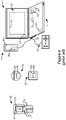
- An SCS system typically includes an Implantable Pulse Generator (IPG) 10 shown in Figure 1 .
- the IPG 10 includes a biocompatible device case 12 that holds the circuitry and battery 14 necessary for the IPG to function.
- the IPG 10 is coupled to tissue-stimulating electrodes 16 via one or more electrode leads that form an electrode array 17.
- one or more percutaneous leads 15 can be used, in which ring-shaped or split-ring electrodes 16 are carried on a flexible body 18, which also houses the individual lead wires 20 coupled to each electrode 16.
- a paddle lead 19 having electrodes 16 positioned on one of its generally flat surfaces also forms an electrode array 17.
- the lead wires 20 are coupled to proximal contacts 22, which are insertable into lead connectors 24 fixed in a header 25 on the IPG 10, which header can comprise an epoxy for example. Once inserted, the proximal contacts 22 connect to header contacts 27 within the lead connectors 24, which are in turn coupled by feedthrough pins 34 through a case feedthrough 32 to circuitry within the case 12, although these details aren't shown.
- the header 25 may include a 2x2 array of eight-electrode lead connectors 24.
- the conductive case 12 can also comprise an electrode (Ec).
- the electrode lead(s) are typically implanted in the spinal column proximate to the dura in a patient's spinal cord, preferably spanning the left and right of the patient's spinal column.
- the proximal contacts 22 are tunneled through the patient's tissue to a distant location such as the buttocks where the IPG case 12 is implanted, at which point they are coupled to the lead connectors 24.
- the IPG can be lead-less, having electrodes 16 instead appearing on the body of the IPG 10 for contacting the patient's tissue.
- the IPG lead(s) can be integrated with and permanently connected the case 12 in other IPG solutions.
- the goal of SCS therapy is to provide electrical stimulation from the electrodes 16 to alleviate a patient's symptoms, such as chronic back pain for example.
- IPG 10 can include an antenna 26a allowing it to communicate bi-directionally with a number of external devices discussed subsequently.
- Antenna 26a as shown comprises a conductive coil within the case 12, although the coil antenna 26a can also appear in the header 25.
- IPG 10 may also include a RadioFrequency (RF) antenna 26b.
- RF antenna 26b is shown within the header 25, but it may also be within the case 12.
- RF antenna 26b may comprise a patch, slot, or wire, and may operate as a monopole or dipole.
- RF antenna 26b preferably communicates using far-field electromagnetic waves.
- RF antenna 26b may operate in accordance with any number of known RF communication standards, such as Bluetooth, Zigbee, WiFi, MICS, and the like.
- Stimulation in IPG 10 is typically provided by pulses, as shown in Figure 2 .
- Stimulation parameters typically include the amplitude of the pulses (current I, although a voltage amplitude V can also be used); the frequency (F) and pulse width (PW) of the pulses; the electrodes 16 activated to provide such stimulation; and the polarity of such active electrodes, i.e., whether active electrodes are to act as anodes that source current to the tissue or cathodes that sink current from the tissue.
- Stimulation parameters taken together comprise a stimulation program that the IPG 10 can execute to provide therapeutic stimulation to a patient.
- electrode E5 has been selected as an anode (during its first phase 30), and thus provides pulses which source a positive current of amplitude +1 to the tissue.
- Electrode E4 has been selected as a cathode (again during first phase 30), and thus provides pulses which sink a corresponding negative current of amplitude -I from the tissue.
- This is an example of bipolar stimulation, in which only two lead-based electrodes are used to provide stimulation to the tissue (one anode, one cathode). However, more than one electrode may act as an anode at a given time, and more than one electrode may act as a cathode at a given time, as discussed subsequently.
- the pulses as shown in Figure 2 are biphasic, comprising a first phase 30, followed quickly thereafter by a second phase 30' of opposite polarity.
- a biphasic pulse is useful in active charge recovery. See, e.g., U.S. Patent Application Publication 2016/0144183 .
- the first and second phases 30 and 30' have the same duration and amplitude (although of opposite polarities), which ensures the same amount of charge during both phases, and thus hopefully full recovery of charge on any capacitance in the current paths.
- the second phase 30' may also be charged balance with the first phase 30 if the product of the amplitude and durations of the two phases are equal, as is well known.
- each pulse, PW is shown as comprising the duration of first pulse phase 30, although pulse width could also refer to the total duration of the first and second pulse phases 30 and 30' as well.
- an interphase period during which no current is driven can intervene between the first and second phases 30 and 30'.
- IPG 10 includes stimulation circuitry 28 ( Fig. 1 ) that can be programmed to produce the stimulation pulses at the electrodes as defined by the stimulation program.
- Stimulation circuitry 28 can for example comprise the circuitry described in U.S. Patent Application Publications 2018/0071513 and 2018/0071520 , or in USPs 8,606,362 and 8,620,436 .
- FIG. 3 shows an external trial stimulation environment that may precede implantation of an IPG 10 in a patient.
- stimulation can be tried on a prospective implant patient without going so far as to implant the IPG 10.
- one or more trial electrode arrays 17' e.g., one or more trial percutaneous leads 15 or trial paddle leads 19
- the proximal ends of the trial electrode arrays(s) 17' exit an incision 36 and are connected to an External Trial Stimulator (ETS) 40.
- ETS 40 External Trial Stimulator
- the ETS 40 generally mimics operation of the IPG 10, and thus can provide stimulation pulses to the patient's tissue as explained above.
- the ETS 40 is generally worn externally by the patient for a short while (e.g., a few weeks), which allows the patient and his clinician to experiment with different stimulation parameters to try and find a stimulation program that alleviates the patient's symptoms (e.g., pain). If external trial stimulation proves successful, trial electrode arrays 17' are explanted, and a full IPG 10 and a permanent electrode array 17 (e.g., one or more percutaneous 15 or paddle 19 lead(s)) are implanted as described above; if unsuccessful, the trial electrode array 17' is simply explanted.
- a full IPG 10 and a permanent electrode array 17 e.g., one or more percutaneous 15 or paddle 19 lead(s)
- the ETS 40 can include one or more antennas to enable bidirectional communications with external devices, as shown in Figure 4 .
- Such antennas can include a near-field magnetic-induction coil antenna 42a, and/or a far-field RF antenna 42b, as described earlier.
- ETS 40 may also include stimulation circuitry able to form the stimulation pulses in accordance with a stimulation program, which circuitry may be similar to or comprise the same stimulation circuitry 28 present in the IPG 10.
- ETS 40 may also include a battery (not shown) for operational power.
- Figure 4 shows various external devices that can wirelessly communicate data with the IPG 10 and the ETS 40, including a patient, hand-held external controller 45, and a clinician programmer 50.
- Both of devices 45 and 50 can be used to send a stimulation program to the IPG 10 or ETS 40-that is, to program their stimulation circuitries 28 to produce stimulation with a desired shape and timing described earlier.
- Both devices 45 and 50 may also be used to adjust one or more stimulation parameters of a stimulation program that the IPG 10 or ETS 40 is currently executing.
- Devices 45 and 50 may also receive information from the IPG 10 or ETS 40, such as various status information, etc.
- External controller 45 can be as described in U.S. Patent Application Publication 2015/0080982 for example, and may comprise a dedicated controller configured to work with the IPG 10. External controller 45 may also comprise a general purpose mobile electronics device such as a mobile phone which has been programmed with a Medical Device Application (MDA) allowing it to work as a wireless controller for the IPG 10 or ETS 40, as described in U.S. Patent Application Publication 2015/0231402 . External controller 45 includes a user interface, preferably including means for entering commands (e.g., buttons 49 or selectable graphical icons) and a display 46. The external controller 45's user interface enables a patient to adjust stimulation parameters, although it may have limited functionality when compared to the more-powerful clinician programmer 50, described shortly.
- MDA Medical Device Application
- the external controller 45 can have one or more antennas capable of communicating with the IPG 10 and ETS 40.
- the external controller 45 can have a near-field magnetic-induction coil antenna 47a capable of wirelessly communicating with the coil antenna 26a or 42a in the IPG 10 or ETS 40.
- the external controller 45 can also have a far-field RF antenna 47b capable of wirelessly communicating with the RF antenna 26b or 42b in the IPG 10 or ETS 40.
- the external controller 45 can also have control circuitry 48 such as a microprocessor, microcomputer, an FPGA, other digital logic structures, etc., which is capable of executing instructions.
- Control circuitry 48 can for example receive patient adjustments to stimulation parameters, and create a stimulation program to be wirelessly transmitted to the IPG 10 or ETS 40.
- the clinician programmer 50 can comprise a computing device 51, such as a desktop, laptop, or notebook computer, a tablet, a mobile smart phone, a Personal Data Assistant (PDA)-type mobile computing device, etc.
- computing device 51 is shown as a laptop computer that includes typical computer user interface means such as a screen 52, a mouse, a keyboard, speakers, a stylus, a printer, etc., not all of which are shown for convenience.
- accessory devices for the clinician programmer 50 that are usually specific to its operation as a stimulation controller, such as a communication "wand" 54, and a joystick 58, which are coupleable to suitable ports on the computing device 51, such as USB ports 59 for example.
- the antenna used in the clinician programmer 50 to communicate with the IPG 10 or ETS 40 can depend on the type of antennas included in those devices. If the patient's IPG 10 or ETS 40 includes a coil antenna 26a or 42a, wand 54 can likewise include a coil antenna 56a to establish near-filed magnetic-induction communications at small distances. In this instance, the wand 54 may be affixed in close proximity to the patient, such as by placing the wand 54 in a belt or holster wearable by the patient and proximate to the patient's IPG 10 or ETS 40.
- the wand 54, the computing device 51, or both can likewise include an RF antenna 56b to establish communication with the IPG 10 or ETS 40 at larger distances. (Wand 54 may not be necessary in this circumstance).
- the clinician programmer 50 can also establish communication with other devices and networks, such as the Internet, either wirelessly or via a wired link provided at an Ethernet or network port.
- GUI clinician programmer graphical user interface
- the GUI 64 can be rendered by execution of clinician programmer software 66 on the computing device 51, which software may be stored in the device's non-volatile memory 68.
- control circuitry 70 such as a microprocessor, microcomputer, an FPGA, other digital logic structures, etc., which are capable of executing programs in a computing device.
- control circuitry 70 in addition to executing the clinician programmer software 66 and rendering the GUI 64, can also enable communications via antennas 56a or 56b to communicate stimulation parameters chosen through the GUI 64 to the patient's IPG 10.
- Control circuitries 48 and 70 in the external controller 45 and clinician programmer 50 can comprise one or more microprocessors, microcomputers, Digital Signal Processors (DSPs), FPGAs, or other circuitry capable of executing programs in a computing device.
- control circuitries 48 and 70 may include or be functionally equivalent to any of the i5 processors manufactured by Intel Corp., as described at https:// www.intel.com/ content/ www/ us/ en/ products/ processors/core/i5-processors.html, and may contain computer readable media (e.g., solid state memories) for storing instructions to implement their functionalities.
- US 2017/189683 A1 discloses an integrated circuit for an implantable wirelessly powered device for implantation in a patient's body.
- US 2018/071516 A1 discloses an improved stimulation circuitry for controlling the stimulation delivered by an implantable stimulator.
- US 2010/114204 A1 discloses medical devices, and, more particularly, systems including two or more medical devices.
- the stimulator device comprises a plurality of electrode nodes, each electrode node configured to be coupled to one of a plurality of electrodes configured to contact a patient's tissue.
- the stimulator device comprises stimulation circuitry configured to execute a stimulation program to provide a stimulation current to at least two of the electrode nodes, wherein the stimulation program comprises a plurality of sub-programs configured to be executed by the stimulation circuitry.
- the stimulator device comprises controller circuitry configured to periodically store information that indicates where the stimulation circuitry is in its execution of the plurality of sub-programs, and if the stimulator device experiences an interruption that prevents the stimulation circuitry from continuing execution of the plurality of sub-programs, use the stored information to continue execution of the plurality of sub-programs at a point corresponding to the interruption.
- the information comprises markers that are pre-defined in the stimulation program.
- the stimulation program comprises at least one block comprising at least one of the sub-programs, and wherein the point corresponding to the interruption comprises a beginning of a first marked sub-program in the at least one block executed when the interruption occurred.
- the information comprises markers that are pre-defined for at least some of the sub-programs, and wherein the point corresponding to the interruption comprises (i) a beginning of a marked sub-program that immediately precedes the sub-program executed when the interruption occurred, or (ii) if the sub-program executed when the interruption occurred is marked, at the beginning of that sub-program.
- the point corresponding to the interruption comprises a beginning of a sub-program executed when the interruption occurred.
- the point corresponding to the interruption comprises a point during the sub-program executed when the interruption occurred.
- the plurality of sub-programs in the stimulation program are configured to be executed sequentially by the stimulation circuitry.
- the controller circuitry is further configured to receive an indication that the stimulation circuitry can continue the execution of the plurality of sub-programs before using the stored information to continue execution of the plurality of sub-programs.
- the indication is automatically generated by the controller circuitry upon removal of an action that caused the interruption.
- the indication is received from an external device in communication with the stimulator device.
- each of the sub-programs selects a different combination of the at least two of the electrode nodes to provide the stimulation current.
- at least some of the different combinations of the at least two electrode nodes comprise bipoles.
- an amplitude of the stimulation current is different during at least some of the sub-programs.
- the stimulation current is sub-threshold during at least some of the sub-programs.
- the interruption is caused by an action comprising one or more of: a depletion of a battery in the stimulator device; a receipt at the stimulator device of an emergency shutdown signal; a change to a new stimulation program; or a pausing of the stimulation program.
- the stimulation device can further comprise one or more implantable leads comprising the plurality of electrodes.
- the stimulator device comprises a fully-implantable pulse generator.
- the stimulator device comprises an external trial stimulator.
- the information that indicates where the stimulation circuitry is in its execution of the plurality of sub-programs comprises information regarding a sub-program that is currently being executed. According to some embodiments, the information that indicates where the stimulation circuitry is in its execution of the plurality of sub-programs comprises information indicating how far a currently-executed one of the sub-programs is towards its completion. According to some embodiments, each of the sub-programs is configured to be executed for a same duration.
- the controller circuitry further comprises or is associated with a pain score memory, wherein the pain score memory is configured to store an association of a pain score wirelessly received at the device with an indication of a sub-program that was being executed at the time the pain score was wirelessly received.
- the controller circuitry further comprises or is associated with a program memory configured to store the stimulation program including each of the plurality of sub-programs.
- a stimulation program that will be effective for each patient to relieve their symptoms, such as pain.
- a significant part of determining an effective stimulation program is to determine the electrodes in the array 17 or 17' that should be selected to provide the stimulation.
- the neural site at which pain originates in a patient, and therefore electrodes proximate to such neural site, can be difficult to determine, and experimentation is typically undertaken to select the best combination of electrodes to provide a patient's therapy.
- SCS traditionally provides a sensation of paresthesia to a patient-i.e., a tingling, prickling or heating sensation.
- Selecting electrodes for a given patient can be easier when paresthesia is present, because the patient can provide feedback to the clinician concerning when the paresthesia seems to "covering" the area that is causing pain.
- the patient can generally assess when the sensation of paresthesia seems to have taken the place of the sensation of pain, which assists in electrode selection.
- sub-threshold stimulation therapy can provide symptom relief without the sensation of paresthesia, which is often called sub-threshold stimulation therapy. See, e.g., U.S. Patent Application Publication 2019/0046800 . Electrode selection for a given patient can be more difficult when paresthesia is not present, because the patient does not feel the stimulation, and therefore it can be difficult for the patient to feel whether the stimulation is covering his pain. Further, sub-threshold stimulation therapy may require a "wash in" period before it can become effective. A wash in period can take up to a day or more, and therefore sub-threshold stimulation may not be immediately effective, making electrode selection more difficult.
- FIG. 5 shows a stimulation program (SP) 100 that can be executed by an IPG 110 or ETS 140 ( Fig. 6 ) to assist in selecting electrodes for a patient, which is particularly useful when sub-threshold stimulation therapy is being provided by the IPG or ETS.
- Stimulation program 100 is particularly useful in a trial setting after a patient is first implanted with an electrode array 17 or 17', i.e., after receiving their IPG 110 or ETS 140.
- stimulation program 100 is comprised of a sequence of sub-programs 102, each of which preferably selects different electrodes for stimulation.
- a site 98 of a patient's pain is likely within a tissue region 99.
- Such region 99 may be deduced by a clinician based on the patient symptoms, e.g., by understanding which electrodes are proximate to certain vertebrae (not shown), such as within the T9-T10 interspace.
- region 99 is bounded by electrodes E2, E7, E15, and E10, meaning that electrodes outside of this region (e.g., E1, E8, E9, E16) are unlikely to have an effect on the patient's symptoms. Therefore, these electrodes are not selected during any of the sub-programs 102; to reduce the size and total duration of the stimulation program 100.
- sub-programs 102 could be constructed for each of the electrodes without regard to a tissue region 99.
- each sub-program 102; of the stimulation program 100 selects two electrodes-a bipole 97-for stimulation.
- electrode E2 is selected as an anode that will source a positive current (+I 1 ) to the patient's tissue
- electrode E3 is selected as a cathode that will sink a negative current (-I 1 ) from the patient's tissue.
- This sub-program 102 1 will be executed by the IPG 110 or ETS 140 for a duration d1.
- sub-program 102 2 selects a different combination of electrodes (anode electrode E3, cathode electrode E4), which moves the location of the bipole 97 in the patient's tissue.
- the sub-programs 102; in the stimulation program 100 move the bipole 97 down one electrode lead, and up the other, as shown by path 96.
- the goal of moving the bipole 97 along path 96, or changing the selected electrodes in each sub-program 102 i more generally, is to try and find an electrode selection that best covers the site 98 of the patient's pain.
- sub-program 7 (102 7 ) will provide the best relief for the patient.
- each sub-program 102 is itself a fully-executable stimulation program, specifying all relevant stimulation parameters, such as amplitude I, frequency f, pulse width PW, although not all of these stimulation parameters are shown in Figure 5 .
- stimulation parameters I, f, and PW can be the same in each sub-program 102;, with the sub-programs 102; differing only in the selected electrodes and their polarities. However, this is not strictly required, and any one or more stimulation parameters can be changed in each stimulation program 102;.
- One stimulation parameter of interest, amplitude I i is shown because it may be useful to titrate this value for each sub-program 102;.
- Titrating the amplitude I i for each sub-program 102; is useful especially when sub-threshold therapy is to be provided during each sub-program 102;.
- a suitable sub-threshold amplitude I i may need to be varied.
- the selected electrodes in each sub-program 102 i comprise bipoles as shown. More complicated electrode selections (e.g., three-electrode tripoles, or electrode combinations spanning the leads) could also be made. Further, the selected electrodes need not comprise physical bipoles defined at two physical electrodes 16. Instead, virtual bipoles (or tripoles, etc.), can be formed in which the pole positions are not necessarily formed at the location of the physical electrodes. See, e.g., U.S. Patent Application Serial No. 16/210,794, filed December 5, 2018 , discussing virtual poles in an implantable stimulator device.
- the sub-programs 102 i can comprise randomly different stimulation programs. That is, any one or more stimulation parameters-selected electrodes, their polarities, amplitude, frequency, pulse width, etc.-can be varied or remain the same during each of the sub-programs. Nonetheless, sub-programs 102 i providing physical bipoles 97 moving step-wise along a path 96 provide a good example, as well as a logical use model designed to assist the patient or clinician in finding a "sweet spot" at which pain 98 is present in the patient's tissue. However, the technique is not limited to this use model.
- Stimulation program 100 is preferably formed at the clinician programmer 150 ( Fig. 6 ), although it may also be formed at any external device in communication with the IPG 110 or ETS 140, such as a patient external controller 145.
- each sub-program 102 is defined using the Graphical User interface (GUI) of the device, and then the sub-programs 102i are concatenated with their durations.
- GUI Graphical User interface
- the stimulation program 100 can end once its last sub-program (102 10 ) has been executed.
- the IPG 110 or ETS 140 can establish a communication link with the clinician program 150 or external controller 145 to notify the clinician or patient of this fact.
- the stimulation program 100 can run in a loop, executing 102 1 , 102 2 , etc. after the execution of 102 10 has completed.
- the GUI of the clinician program 150 or external controller 145 can allow the clinician or patient to specify the number of loops that the stimulation program will be executed by the IPG 110 or ETS 140.
- each sub-program 102 is preferably run for a significant duration, which might comprise two to three days. Durations di are preferably the same for each of the sub-programs 102 i , but could also be different.
- the patient may use the GUI of his external controller 145 to qualitatively rate therapy effectiveness by entering a pain score 104.
- This can comprise the use of a pain rating scale, such as the Numerical Rating Scale (NRS) or the Visual Analogue Scale (VAS).
- NRS Numerical Rating Scale
- VAS Visual Analogue Scale
- Such scales allow the patient to rank pain on a scale of 1 to 10, with 1 denoting no or little pain and 10 denoting a worst pain imaginable.
- the patient preferably enters a pain score 104 at least a few times per day, although the patient need not do so on a strict schedule. System treatment of the entered pain scores 104 is discussed further below.
- FIG. 5 Also shown in Figure 5 is a calculation of the power W i 171; that each sub-program 102; will expend in the IPG 110 or ETS 140.
- Such power values W i can be calculated or estimated in one example by multiplying the amplitude I, the frequency f, and pulse width PW used during each sub-program 102;.
- the power values W i may also include estimations of the power expended by the IPG 110 or ETS 140 when performing functions apart from the provision of stimulation, such as the quiescent power draw of the IPG or ETS's components, power drawn during telemetry, etc.
- the power W i of each sub-program 102 i can be important to consider, as battery power in the IPG 110 or ETS 140 may be limited.
- Power W i may also be indicative of energy over a period of time, e.g., the power W i times the duration di of each sub-program 102 i .
- the power 171 i of each sub-program 102 i can also comprise a power actually measured in the IPG 110 or ETS 140 as each sub-program 102 i is executing.
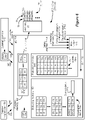
- FIG. 6 shows further details of the IPG 110 or ETS 140 in conjunction with external devices that communicate with them, such as clinician programmer 150 and patient external controller 145.
- IPG 110, ETS 140, clinician programmer 150 and external controller 145 may generally function and be constructed as described in Introduction, although each have additional features as described herein.
- the control circuitry 160 more generally can comprise a microprocessor, Field Programmable Grid Array, Programmable Logic Device, Digital Signal Processor or like devices.
- Control circuitry 160 may include a central processing unit capable of executing instructions, with such instructions stored in volatile or non-volatile memory within or associated with the control circuitry.
- Control circuitry 160 may also include, operate in conjunction with, or be embedded within an Application Specific Integrated Circuit (ASIC), such as described in U.S. Patent Application Publications 2008/0319497 , 2012/0095529 , 2018/0071513 , or 2018/0071520 .
- the control circuitry 160 may comprise an integrated circuit with a monocrystalline substrate, or may comprise any number of such integrated circuits operating as a system.
- Control circuitry may also be included as part of a System-on-Chip (SoC) or a System-on-Module (SoM) which may incorporate memory devices and other digital interfaces.
- SoC System-on-Chip
- SoM System-on-Module
- Control circuitry 160 can include or interface with a program memory 162, which stores the stimulation program, such as stimulation program (SP) 100, that the IPG 110 or ETS 140 is running.
- the stimulation program 100 inclusive of its sub-programs 102; and their durations di, can be wirelessly telemetered to the IPG 110 or ETS 140 by either the clinician program 150 or the external controller 145 and stored in the program memory 162.
- the program memory 162 can also store a number of loops that the stimulation program 100 will execute, which as noted earlier can be specified at the relevant external device.
- the control circuitry 160 executes the stimulation program 100 by executing each sub-program 102; sequentially, and in accordance with the duration di of each.
- Clock circuitry 164 with the IPG 110 or ETS 140 assists with timing and, in conjunction with the durations d i , can inform the control circuitry 160 when the duration of a currently-executed sub-program 102; has expired, and when execution of a next sub-program 102 i+1 should begin.
- Clock circuitry 164 provides a timing reference t for the IPG 110 or ETS 140.
- the program memory 162 passes various stimulation parameters for each sub-program 102; to stimulation circuitry 28, which stimulation parameters can comprise the current amplitude (I), the electrodes (E) (e.g., the bipole 97) chosen for stimulation, the polarity (P) of the selected electrodes (whether they are to act as anodes or cathodes), and timing information including the frequency (f) and the pulse width (PW).
- the stimulation circuitry 28 can then form stimulation (e.g., pulses) at the selected electrodes with the correct amplitude and timing.
- stimulation circuitry 28 may comprise a portion of the control circuitry 160.
- the pain scores 104; entered by the patient using his external controller 145 are wirelessly telemetered to and stored in the IPG 110 or ETS 140, and specifically in a pain score memory 166. It is useful to know when the patient entered a particular pain score 104;, and so each pain score 104; can be associated with a timing reference T i provided by clock circuitry 168 operating in the external controller 145. Time T i can comprise a real time clock, and can comprise a time reference different from the time t output by the clock circuitry 164 in the IPG 110 or ETS 140. However, these two timing references t and T can be synchronized when the IPG 110 or ETS 140 is in communication with the external controller 145, as explained in USP 8,065,019 .
- the contents of pain score memory 166 can be read out of the IPG 110 or ETS 140 and telemetered to the clinician programmer 150 or external controller 145 for evaluation. Such evaluation can occur and be depicted at these external devices in different ways, but Figure 7 shows one such example.
- Figure 7 shows control circuitry 181 in the clinician programmer 150 or external controller 145, which may be similar to the control circuities described earlier (e.g., 48, 70, Fig. 4 ).
- the pain scores 140; associated with each sub-program 102; can be stored in an evaluation memory 172, and can be graphed on the displays 52 or 46 of the clinician programmer 150 or external controller 145 as shown.
- the pain scores 140; for each sub-program 102; can be averaged to provide an average pain score 170; for each sub-program 102;, as shown in the memory 172.
- an average pain score 170; for each sub-program 102; can be calculated in different ways, and in view of different practical considerations. For example, a patient's pain may vary depending on the time of day and based on activity or patient position. There may also be aberrant data points 140; that might be discarded from the pain score average 170;. It may also be useful to ignore any data points 140; occurring early in the duration di of each sub-program 102;, as therapy may be washing in during that time.
- the average pain scores 170; can also be graphed as shown. Presenting the data in this or other fashions (e.g., as a list) can assist the clinician or patient to better understand which sub-program(s) 102;, i.e., which bipole 97 combinations, seem to work best for the patient.
- evaluation memory 172 optionally included in evaluation memory 172 are the power values 171; calculated for each of the sub-programs 102 i , as discussed earlier with reference to Figure 5 . These power values may also be illustrated or graphed on the display screen 52 or 46 of the clinician programmer 150 or external controller 145. The power values 171; may be scaled as is convenient, but are shown in the Figures as Watts x 10 -5 .
- the data displayed in Figure 7 assists in locating the site 98 ( Fig. 5 ) of the patient's pain, and can be used as a basis for further experimentation.
- sub-program 102 1 provided the patient the best pain relief, as the (average) pain scores are lower for this sub-program.
- the site 98 of the patient's pain is proximate to electrodes E2 and E3 selected during sub-program 102 1 ( Fig. 5 ). Given these results, it may be sensible thereafter for the patient to use sub-program 102 1 as his therapy going forward.
- a new sub-program (e.g., 102 11 ; not shown) which changes the stimulation parameters associated with sub-program 102 1 .
- the amplitude, frequency, or pulse width of sub-program 102 1 could be changed.
- new electrodes could be selected in the general vicinity of sub-program 102 1 's E2/E3 bipole 97.
- a tripole consisting of electrodes E1/E2/E3 or E2/E3/E4 could be tried.
- E2 and E3 could also be tried, such as E2/E10 or E3/E11.
- Such new sub-program 102 11 can be evaluated on its own as before-by running it for a duration d11, and having the patient enter pain scores 140; during that duration, to see if the patient's pain scores can be further decreased.
- new sub-program 102 11 could be manually or automatically be included in the stimulation program 100.
- stimulation program 100 An issue concerning stimulation program 100 is the length of time it must run to fully complete execution and evaluation of each sub-program 102;. As noted earlier, given the sub-threshold nature of the therapy, and the need for a wash in period, each sub-program 102; may take two to three days (di). If it is assumed that stimulation program 100 includes ten sub-programs 102;, it would take 20-30 days to run stimulation program 100 in its entirety.
- the battery in the IPG 110 or ETS 140 may deplete to a level that the IPG 110 or ETS 140 will not function. This may be because these devices have rechargeable batteries that the patient neglects to wirelessly recharge. See, e.g., U.S. Patent Application Publication 2017/0361113 , describing an external charger for an implantable device. Interruption may also occur if the IPG 110 or ETS 140 detects an emergency shutdown, such as provided by an external bar magnet. See, e.g., USP 8,473,070 , describing emergency shutdown of an implantable device.
- Interruption of the stimulation program 100 may also occur simply because the clinician or patient uses an external device 145 or 150 to change the stimulation program, perhaps to temporarily try different stimulation parameters. Interruption of the stimulation program 100 may also occur because an external device 145 or 150 is used to pause the stimulation program 100. These are just non-limiting examples of actions that can interrupt execution of stimulation program 100 in the IPG 110 or ETS 140, and others actions may cause interruption as well.
- the control circuitry 160 in the IPG 110 or ETS 140 is able to detect where stimulation program 100 is in its operation, and can generally resume operation where it left off.
- a status log memory 180 preferably periodically stores an indication of the sub-program 102; currently being executed as well as a status 182 of that sub-program.
- Sub-program status 182 in this example comprises an indication of how far along the current sub-program 102; is in its execution. This status can be indicated in any number of ways, but for simplicity is shown in Figure 6 as comprising a percentage to completion (X%).
- the data in status log memory 180 can also be associated with a timing reference t provided by the clocking circuitry 164 in the IPG 110 or ETS 140, which again can be synchronized with the timing reference T provided in an external device if desirable. Timing reference t can be used in conjunction with the durations di to compute a percent completion value X%. Data can be logged periodically in the status log memory 180, but periodicity does not imply that data is necessarily stored at a set frequency or interval. That being said, data is preferably stored in the status log memory 180 at a set frequency, such as once an hour. Note that the various memories in the IPG 110 or ETS 140-such as 162, 166, and 180-can comprise memory addresses in a single memory within or accessible to the control circuitry 160.
- While the status log memory 180 can comprise a historical log, it can be simpler to move the current status-i.e., the last logged entry-into its own memory location 184. This way, upon receiving an indication that the stimulation circuitry 28 can begin re-executing the stimulation program 100, the current status register 184 can simply be queried to know where to begin execution. In fact, status log memory 180 need not have historical log information, so long as current status register 184 is continually updated.
- Current status register 184 is preferably a non-volatile memory, and so will retain its data even if power to the IPG 110 or ETS 140 fails or is removed. Other memories present in the IPG 110 or ETS 140 are preferably also non-volatile memories.
- An interruption logic module 176 can receive indications of the various types of actions that can interrupt execution of the stimulation program 100, and can issue an interrupt INT 178 when any relevant action has occurred. Interrupt 178 can cause the status log memory 180 to populate the current status register 184, and may also disable the program memory 162 or the stimulation circuitry 28.
- Actions indicating the need to interrupt execution of the stimulation program 100 can come from different sources in the IPG 110 or ETS 140.
- a battery deletion indicator 175a can come from battery voltage sensing circuitry (not shown), which monitors the voltage Vbat of the IPG or ETS's battery, and asserts the indicator 175 to the interruption module 176 when Vbat falls below a threshold Vt.
- the threshold Vt would be set just a bit higher (e.g., 0.1V more) than the voltage needed for the IPG 110 or ETS 140 to operate. This allows some time (0.1 Volts' worth) to allow the IPG 110 or ETS 140 to take appropriate shutdown steps before the IPG or ETS truly become non-functional, such as stopping stimulation, logging various IPG or ETS status data, etc.
- the emergency shutdown indicator 175b can come from a magnetic Reed or Hall sensor (not shown) in the IPG 110 or ETS 140, which can be activated by placement of an emergency shutdown bar magnet in the vicinity of the IPG or ETS.
- Emergency shutdown may cause the IPG or ETS's circuitry to become disconnected from its battery, but before this a short delay period can be provided to allow the IPG 110 or ETS 140 to take appropriate shutdown steps. See, e.g., USP 8,473,070 , explaining emergency shutdown and a shutdown delay period.
- An indicator that the stimulation program has been (temporarily) changed (175c) or paused (175d) can come from the program memory 162.
- interrupt 178 will deassert.
- the stimulation program 100 can continue its execution. Continuing the execution of the stimulation program 100 can occur automatically in the IPG 110 or ETS 140 without patient or clinician intervention. This can occur by having the control circuitry 160 read the data in the current status register 184.
- the current status register 184 preferably stores an indication of the sub-program 102 i that was being executed at the time of the interruption (e.g., sub-program 102 5 in Fig. 5 ) as well as a sub-program status 182 indicative of how far along that sub-program was towards it completion (e.g., X%).
- the control circuitry 160 may therefore continue the execution of the stimulation program 100 by starting back at the beginning 183 of sub-program 102 5 , or using the sub-program status 182 (e.g., X%) to start at some point in the middle of sub-program 102 5 where it left off, as shown in Figure 5 .
- the IPG 110 or ETS 140 will automatically continue execution at the beginning 183 or in the middle 182 of the sub-program can be a feature that a clinician or patient may pre-program in the IPG or ETS prior to execution of the stimulation program 100.
- the interrupted sub-program e.g., 102 5
- different factors may determine which starting point will be used. For example, if the interruption of the stimulation program 100 has occurred for a long time, such as longer than a threshold of 12 hours, it may be beneficial to start at the beginning 183 of interrupted sub-program 102 5 to allow that sub-program to properly wash back in. By contrast, if the interruption is short, such as less than the 12 hour threshold, it may be reasonable to begin in the middle 182 where sub-program 102 5 was interrupted.
- whether to begin at the beginning 183 or middle 182 of the interrupted sub-program 102 5 may depend on how far that sub-program was in its execution (e.g., X%). For example, if X is less than a threshold, it may be reasonable to start at the beginning 183, because the sub-program 102 5 was not very far along in its execution anyway. If X is greater than a threshold, it may be reasonable to start in the middle 182, because the sub-program 102 5 was already relatively close to finishing.
- Continuing of execution of the stimulation program 100 may not be automatic in the IPG 110 or ETS 140, and instead may only commence upon receipt of permission from the clinician or patient.
- the IPG 110 or ETS 140 can attempt to establish a communication session with the clinician program 150 or external controller 145. Once a communication link is established, the IPG 110 or ETS 140 can send the contents of current status register 184 to the relevant external device 150 or 145 and present the clinician or patient with a notification 190 such as that shown in Figure 8 .
- This notification 190 can inform the user, using the information in register 184, that the stimulation program 100 was interrupted (i) during sub-program 102 5 , or may further inform the user that (ii) sub-program 102 5 was interrupted X% into its execution. Based on this notification 190, the user can then choose an option to continue stimulation program 100 (i) at the beginning of sub-program 102 5 (183), or (ii) X% into sub-program 102 5 (182). As just discussed, there can be logic to continuing execution at either of these points in time.
- Data received at the clinician programmer 150 or external controller 145 can also be used to assess the stimulation program 100 after its completion, and to identify sub-programs 102 i in the stimulation program 100 that are beneficial for the patient.
- control circuitry 181 in the clinician programmer 150 or external controller 145 can include stimulation program assessment logic 186 that can be used to automatically select sub-programs 102; that are beneficial, and to discard sub-programs 102; that are not. While stimulation program adjust logic 186 can be configured in different ways, the illustrated example allows each sub-program 102; to be assessed using a pain threshold (Pt) 174 and using power assessment logic 188.
- Pt pain threshold
- FIG. 9 An example of how the stimulation program assessment logic 186 can be used to assess the stimulation program 100 is shown in Figure 9 . Shown are the results of stimulation program 100 after its execution, including for each sub-program 102; the average pain score 170; and the power draw 171;, which information can be pulled from evaluation memory 172 in the external device ( Fig. 7 ) as discussed previously. Suitable sub-programs 102; are first assessed using the pain threshold (Pt) 174. In this example, the pain threshold is set to a 5, such that sub-programs 102; having an average pain score 170; higher than this threshold are discarded as being ineffective for the patient, while sub-programs 102; having an average pain score 170; lower than this threshold are retained as being effective for the patient.
- the pain threshold is set to a 5, such that sub-programs 102; having an average pain score 170; higher than this threshold are discarded as being ineffective for the patient, while sub-programs 102; having an average pain score 170;
- use of the pain threshold 174 causes sub-programs 102 2 to 102 8 to be discarded, while sub-programs 102 1 , 102 9 , and 102 10 are kept because they have suitably low average pain scores (3.3, 4.1, and 3.5 respectively).
- the remaining sub-programs 102 1 , 102 9 , and 102 10 are assessed using power assessment logic 188 to further identify at least one sub-program 102 i that is suitable for the patient based on its power draw.
- power assessment logic 188 picks the remaining sub-program 102 1 , 102 9 , or 102 10 that has the lowest power draw-in this example, sub-program 102 9 .
- This simple example assumes that all remaining sub-programs are equally effective (or at least, are effective) for the patient, and thus the best of those remaining sub-programs is the one with the lowest power draw and thus the one that will be most considerate of the IPG 110 or ETS 140's battery.
- stimulation program assessment logic 186 can select a plurality of sub-programs 102; as being effective for the patient, rather than just one. Stimulation program assessment logic 186 can additionally assess the sub-programs 102; based on factors beyond pain control effectiveness and power draw. In any event, remaining sub-programs 102; can comprise therapeutic stimulation programs that the patient can choose to use, or can comprise a starting point for the discovery of further stimulation programs, as described earlier.
- this current sub-program may be providing poor results for the patient; for example, the patient may be experiencing significant pain or other side effects from the therapy that sub-program 102 5 provides, so much so that it is not worth allowing this sub-program to finish its duration.
- Figure 10B shows the effect of skipping sub-program 102 5 .
- the clinician programmer 150 or external controller 145 sends an instruction to the IPG 110 or ETS 140 to ignore any remaining duration (d5) that sub-program 102 5 may have, and to cause program memory 162 ( Fig. 6 ) to send the stimulation parameters for next sub-program 102 6 to the stimulation circuitry 28 for execution.
- Figure 10C shows the effect of deleting sub-program 102 5 .
- This option will also send an instruction to the IPG 110 or ETS 140 to cause program memory 162 ( Fig. 6 ) to send the stimulation parameters for next sub-program 102 6 to the stimulation circuitry 28 for execution, but will additionally delete sub-program 102 5 from the program memory 162.
- Deletion of a sub-program will preferably also delete that sub-program from the stimulation program 100 as stored on the relevant external device 150 or 145 itself. Note that deletion of a sub-program 102; may also occur before or after the execution of stimulation program 100 in the IPG 110 or ETS 140.
- Computer instructions used in the external devices 145 and 150 including those used to create the stimulation program 100 and its sub-programs 102;, to render and receive inputs from the GUIs, and those used by the control circuitry 181, can be stored on a non-transitory computer readable media, such as a solid state, optical, or magnetic memory, and can be loaded into the relevant external device from an external source, e.g., as downloaded from an Internet Server.
- a non-transitory computer readable media such as a solid state, optical, or magnetic memory
- optical stimulation may be provided to neural tissue using light (or EM radiation more generally), with the device's "electrodes” providing optical energy to the tissue instead of electrical energy.
- Still other forms of stimulation can be used as well, including chemical stimulation, magnetic stimulation, thermal stimulation, mechanical stimulation, etc.
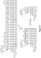
- Figures 11 and 12 show another example of how the IPG of ETS 140 can track progress of a stimulation program 100, and how the program can be continue execution at a logical point after experiencing an interruption.
- the stimulation program or more specifically certain of its sub-programs 102;, can contain markers Mx to inform the IPG 110 or ETS 140 as to where to begin after an interruption.
- the starting points are pre-defined in the stimulation program 100 and/or its sub-programs 102;.
- this example shows that the disclosed technique is not limited to assessment of sub-threshold therapies, and instead shows implementation of the technique using sub-programs 102; with random types of pulses which may be sub- or supra-threshold.
- This example omits for clarity the additional feature of allowing a patient to associate a pain score with each sub-program, as this feature is not strictly necessary in all examples, although this feature could also be used in this example as described above.
- Figure 11 shows a stimulation program 100 defined by sub-programs 102; that as before will be sequentially executed by the IPG 110 or ETS 140.
- the sub-programs 102 may be grouped into blocks 200;, with each block including one or more sub-programs.
- block 200 1 includes sub-programs 102 1 -102 3 ;
- block 200 2 includes sub-programs 102 4 -102 7 ;
- block 200 3 includes sub-program 102 8 ;
- block 200 4 includes sub-programs 102 9 -102 10 .
- Each of the blocks 200 may have pulses that are similar in nature, but varying with respect to one or more stimulation parameters.
- block 200 1 is used via its sub-programs 102 1 -102 3 to form pulses that are biphasic at electrodes E2 (anode) and E3 (cathode), and with a common frequency F1 and pulse width PW1.
- the amplitude of the pulses differs during each of the sub-programs, increasing from I1 in 102 1 to 12 in 102 2 and 13 in 102 3 .
- the number of pulses formed during each sub-program can also be specified, with 4 pulses in 102 1 , 4 pulses in 102 2 , and 25 pulses in 102 3 .
- Block 200 2 is used via its sub-programs 102 3 -102 7 to form pulses with a sinewave shape at electrodes E3 (anode) and E4 (cathode), and with a common frequency F2 and pulse width PW2.
- the amplitude of the pulses differs during each of the sub-programs, decreasing from 14 in 102 4 to 13 in 102 5 to 12 in 102 6 and to I1 in 102 7 .
- Block 200 2 may also have different numbers of pulses formed during each of its sub-programs 102 3 -102 7 as shown.
- Blocks 200 3 and 200 4 specify monopolar pulses ("mono") which involve the use of the case electrode Ec. It is not however required that the sub-programs 102; within a block 200; have pulses that are similar in nature (e.g., increasing or decreasing in amplitude), and instead the stimulation parameters for sub-programs within a block may simply be random.
- a stimulation program 100 such as illustrated in Figure 11 can be defined at the GUI of an external device such as the clinician programmer 150 or external controller 145, and telemetered to the IPG 110 or ETS 140 as before.
- Figure 11 may also generally represent the GUI of such external devices, which provides inputs to allow the clinician to define the sub-programs 102; by entering or adjusting the stimulation parameters, and in particular provides one or more inputs to allow the clinician to define which sub-programs should be marked with a marker Mi.
- such stimulation programs 100 can be defined using the techniques and systems disclosed in U.S. Patent Application Publication 2018/0071513 .
- stimulation parameters indicative of the duration of the sub-programs 102 are effectively dictated by virtue of other timing-related stimulation parameters (e.g., frequency, pulse width, number of pulses, etc.), the sub-programs 102 i may not be explicitly associated with a duration (di) as in the earlier example ( Fig. 5 ).
- the blocks 200 include a marker Mx, which may be stored with or associated with each sub-program 102; within a block, or which (as shown) may only be stored with or associated with only the first sub-program in a block.
- each marker is associated with one of the blocks of sub-program(s): marker M1 is associated with block 200 1 (sub-programs 102 1-3 ), M2 with 200 2 (102 4-7 ); M3 with 200 3 (102 8 ); and M4 with 200 4 (102 9-10 ),
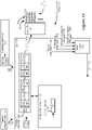
- Each marker Mx informs the IPG or 110 or ETS 140 where the stimulation program will continue execution once a condition leading to an interruption has been removed, as explained further below. As shown in Figure 12 , these markers can be stored in the program memory 162 of the IPG 110 or ETS 140 along with the other stimulation parameters used by the stimulation circuitry 28.
- a marker associated with that sub-program or block can be stored in the current status register 184, which will inform the IPG 110 or ETS 140 where to continue execute after an interrupt condition is removed.
- marker M1 is stored in the current status register.
- the marker can comprise any indicator that informs the IPG 110 or ETS 140 of the sub-program or block with which it is associated, such as a pointer to an address where sub-program 102 1 can be located in the program memory 162.
- sub-program 102 2 is not associated with a new marker, or is associated with the same marker as sub-program 102 1 by virtue of being in the same block 200 1 . Therefore, marker M1 remains in the current status register 184, and the same occurs when sub-program 102 3 is executed.
- sub-program 102 4 in a new block 200 2 is executed, a new marker M2 is stored in current status register 184, and so on.
- the current status register 184 is read, and in association with the program memory 162 continues execution at a point corresponding to the interruption.
- this point comprises the beginning of the block 200i in which the interruption occurred, or more specifically at the start of a first sub-program 102i in the block. For example, if an interruption occurs during any of sub-programs 102 1-3 in block 200 1 , continued execution of the stimulation program will begin at the beginning of block 200 1 , i.e., at the beginning of sub-program 102 1 .
- Allowing the user or clinician to pre-define such markers in the stimulation program 100 can be beneficial, and resuming stimulation at marker M1 provides a good example.
- the point of block 200 1 is to provide pulses that via sub-programs 102 1-3 increase over time, as this eases the introduction of therapy to the patient. If as in Figure 11 an interruption occurs during sub-program 102 3 , when the amplitude is highest, resuming execution of the stimulation program at the start of this sub-program 102 3 might be jarring to the patient.
- a user or clinician compiling a stimulation program can use markers Mx to pre-define sensible or therapeutically-beneficial points where stimulation program 100 execution can be continued after its interruption.
Landscapes
- Health & Medical Sciences (AREA)
- Animal Behavior & Ethology (AREA)
- Public Health (AREA)
- Engineering & Computer Science (AREA)
- Biomedical Technology (AREA)
- Nuclear Medicine, Radiotherapy & Molecular Imaging (AREA)
- Radiology & Medical Imaging (AREA)
- Life Sciences & Earth Sciences (AREA)
- General Health & Medical Sciences (AREA)
- Veterinary Medicine (AREA)
- Neurosurgery (AREA)
- Neurology (AREA)
- Physics & Mathematics (AREA)
- Electromagnetism (AREA)
- Acoustics & Sound (AREA)
- Pain & Pain Management (AREA)
- Heart & Thoracic Surgery (AREA)
- Electrotherapy Devices (AREA)
Claims (15)
- Stimulatorvorrichtung (10), die aufweist:mehrere Elektrodenknoten, wobei jeder Elektrodenknoten konfiguriert ist, mit einer von mehreren Elektroden (16) gekoppelt zu werden, die konfiguriert sind, Gewebe eines Patienten zu berühren;eine Stimulationsschaltung (28), die konfiguriert ist, ein Stimulationsprogramm auszuführen, um einen Stimulationsstrom für mindestens zwei der Elektrodenknoten bereitzustellen, wobei das Stimulationsprogramm mehrere Unterprogramme aufweist, die konfiguriert sind, von der Stimulationsschaltung (28) ausgeführt zu werden; undeine Steuerschaltung, dadurch gekennzeichnet, dass die Steuerschaltung konfiguriert ist, periodisch Informationen zu speichern, die anzeigen, wo sich die Stimulationsschaltung (28) in ihrer Ausführung der mehreren Unterprogramme befindet, undfalls die Stimulatorvorrichtung (10) eine Unterbrechung erfährt, die die Stimulationsschaltung (28) daran hindert, die Ausführung der mehreren Unterprogramme fortzusetzen, die gespeicherten Informationen zu verwenden, um die Ausführung der mehreren Unterprogramme an einem Punkt fortzusetzen, der der Unterbrechung entspricht.
- Stimulatorvorrichtung nach Anspruch 1, wobei die Informationen Markierungen aufweisen, die in dem Stimulationsprogramm vordefiniert sind.
- Stimulatorvorrichtung nach Anspruch 2, wobei das Stimulationsprogramm mindestens einen Block aufweist, der mindestens eines der Unterprogramme aufweist, und wobei der Punkt, der der Unterbrechung entspricht, einen Anfang eines ersten markierten Unterprogramms in dem mindestens einen Block aufweist, der ausgeführt wurde, als die Unterbrechung auftrat.
- Stimulatorvorrichtung nach Anspruch 1, wobei die Informationen Markierungen aufweisen, die für mindestens einige der Unterprogramme vordefiniert sind, und wobei der Punkt, der der Unterbrechung entspricht, aufweist: (i) einen Beginn eines markierten Unterprogramms, das dem Unterprogramm unmittelbar vorausgeht, das ausgeführt wurde, als die Unterbrechung auftrat, oder (ii) falls das Unterprogramm markiert ist, das ausgeführt wurde, als die Unterbrechung auftrat, den Beginn dieses Unterprogramms.
- Stimulatorvorrichtung nach Anspruch 1, wobei der Punkt, der der Unterbrechung entspricht, einen Anfang eines Unterprogramms aufweist, das ausgeführt wurde, als die Unterbrechung auftrat, oder wobei der Punkt, der der Unterbrechung entspricht, einen Punkt während des Unterprogramms aufweist, das ausgeführt wurde, als die Unterbrechung auftrat.
- Stimulatorvorrichtung nach Anspruch 1, wobei die mehreren Unterprogramme im Stimulationsprogramm konfiguriert sind, durch die Stimulationsschaltung sequentiell ausgeführt zu werden.
- Stimulatorvorrichtung nach einem der Ansprüche 1 bis 6, wobei die Steuerschaltung ferner konfiguriert ist, eine Anzeige zu empfangen, dass die Stimulationsschaltung die Ausführung der mehreren Unterprogramme fortsetzen kann, bevor sie die gespeicherten Informationen verwendet, um die Ausführung der mehreren Unterprogramme fortzusetzen.
- Stimulatorvorrichtung nach Anspruch 7, wobei die Anzeige automatisch von der Steuerschaltung erzeugt wird, wenn eine Aktion, die die Unterbrechung verursacht hat, aufgehoben wird, oder wobei die Anzeige von einer externen Vorrichtung empfangen wird, die mit der Stimulatorvorrichtung in Verbindung steht.
- Stimulatorvorrichtung nach einem der Ansprüche 1 bis 8, wobei jedes der Unterprogramme eine andere Kombination der mindestens zwei Elektrodenknoten auswählt, um den Stimulationsstrom bereitzustellen, oder wobei sich eine Amplitude des Stimulationsstroms während mindestens einiger der Unterprogramme unterscheidet.
- Stimulatorvorrichtung nach einem der Ansprüche 1 bis 9, wobei der Stimulationsstrom mindestens während einiger der Unterprogramme unterschwellig ist.
- Stimulatorvorrichtung nach einem der Ansprüche 1 bis 10, wobei die Unterbrechung durch eine Aktion verursacht wird, die eines oder mehreres aufweist von: Entleerung einer Batterie in der Stimulatorvorrichtung; Empfang eines Notabschaltsignals an der Stimulatorvorrichtung; Wechsel zu einem neuen Stimulationsprogramm; oder Pausierung des Stimulationsprogramms.
- Stimulatorvorrichtung nach einem der Ansprüche 1 bis 11, die ferner eine oder mehrere implantierbare Leitungen aufweist, die die mehreren Elektroden aufweisen, wobei die Stimulatorvorrichtung einen vollständig implantierbaren Impulsgenerator aufweist oder wobei die Stimulatorvorrichtung einen externen Probestimulator aufweist.
- Stimulatorvorrichtung nach einem der Ansprüche 1 bis 12, wobei die Informationen, die anzeigen, wo sich die Stimulationsschaltung in ihrer Ausführung der mehreren Unterprogramme befindet, Informationen bezüglich eines Unterprogramms aufweisen, das gerade ausgeführt wird, oder wobei die Informationen, die anzeigen, wo sich die Stimulationsschaltung in ihrer Ausführung der mehreren Unterprogramme befindet, Informationen aufweisen, die anzeigen, wie weit sich ein gerade ausgeführtes Unterprogramm in Richtung seines Abschlusses befindet.
- Stimulatorvorrichtung nach einem der Ansprüche 1 bis 13, wobei die Steuerschaltung ferner einen Schmerz-Score-Speicher aufweist oder mit diesem verbunden ist, wobei der Schmerz-Score-Speicher konfiguriert ist, eine Verknüpfung eines drahtlos an der Vorrichtung empfangenen Schmerz-Score mit einer Anzeige eines Unterprogramms zu speichern, das zu dem Zeitpunkt ausgeführt wurde, als der Schmerz-Score drahtlos empfangen wurde.
- Stimulatorvorrichtung nach einem der Ansprüche 1 bis 14, wobei die Steuerschaltung ferner einen Programmspeicher aufweist oder mit diesem verbunden ist, der konfiguriert ist, das Stimulationsprogramm einschließlich jedes der mehreren Unterprogramme zu speichern.
Applications Claiming Priority (3)
| Application Number | Priority Date | Filing Date | Title |
|---|---|---|---|
| US201862680539P | 2018-06-04 | 2018-06-04 | |
| US201862748031P | 2018-10-19 | 2018-10-19 | |
| PCT/US2019/033583 WO2019236298A1 (en) | 2018-06-04 | 2019-05-22 | Logging the execution of sub-programs within a stimulation program for an implantable stimulator device |
Publications (2)
| Publication Number | Publication Date |
|---|---|
| EP3801741A1 EP3801741A1 (de) | 2021-04-14 |
| EP3801741B1 true EP3801741B1 (de) | 2022-07-20 |
Family
ID=66858008
Family Applications (1)
| Application Number | Title | Priority Date | Filing Date |
|---|---|---|---|
| EP19730618.6A Active EP3801741B1 (de) | 2018-06-04 | 2019-05-22 | Protokollierung der ausführung von unterprogrammen innerhalb eines stimulationsprogramms für eine implantierbare stimulatorvorrichtung |
Country Status (3)
| Country | Link |
|---|---|
| US (3) | US11160987B2 (de) |
| EP (1) | EP3801741B1 (de) |
| WO (1) | WO2019236298A1 (de) |
Families Citing this family (24)
| Publication number | Priority date | Publication date | Assignee | Title |
|---|---|---|---|---|
| US11413458B2 (en) | 2011-05-19 | 2022-08-16 | Neuros Medical, Inc. | Nerve cuff electrode for neuromodulation in large human nerve trunks |
| US12564717B2 (en) | 2017-08-11 | 2026-03-03 | Boston Scientific Neuromodulation Corporation | Paresthesia-free spinal cord stimulation occurring at lower frequencies involving perception threshold determinations |
| US11612751B2 (en) | 2017-08-11 | 2023-03-28 | Boston Scientific Neuromodulation Corporation | Stimulation configuration variation to control evoked temporal patterns |
| US11844947B2 (en) | 2017-08-11 | 2023-12-19 | Boston Scientific Neuromodulation Corporation | Spinal cord stimulation occurring using monophasic pulses of alternating polarities and passive charge recovery |
| US11951314B2 (en) | 2017-08-11 | 2024-04-09 | Boston Scientific Neuromodulation Corporation | Fitting algorithm to determine best stimulation parameter from a patient model in a spinal cord stimulation system |
| US20200147400A1 (en) | 2017-08-11 | 2020-05-14 | Boston Scientific Neuromodulation Corporation | Prescribed Neuromodulation Dose Delivery |
| US11975196B2 (en) | 2017-08-11 | 2024-05-07 | Boston Scientific Neuromodulation Corporation | Tools to assist spinal cord stimulation self-reprogramming |
| US12485273B2 (en) | 2017-08-11 | 2025-12-02 | Boston Scientific Neuromodulation Corporation | Modelling relationships between stimulation parameters and use thereof for automatic customization of sub-perception therapy in a spinal cord stimulation system |
| US12090324B2 (en) | 2017-08-11 | 2024-09-17 | Boston Scientific Neuromodulation Corporation | Spinal cord stimulation for dorsal column recruitment or suppression using anodic and cathodic pulses |
| JP7219261B2 (ja) | 2017-08-11 | 2023-02-07 | ボストン サイエンティフィック ニューロモデュレイション コーポレイション | 錯感覚のない脊髄刺激システム |
| KR102648346B1 (ko) | 2017-12-13 | 2024-03-15 | 뉴로스 메디컬 인코포레이티드 | 신경 커프 배치 장치 |
| CN112188915A (zh) | 2018-04-09 | 2021-01-05 | 纽若斯医疗公司 | 用于设置电剂量的装置和方法 |
| US11890480B2 (en) | 2018-07-03 | 2024-02-06 | Boston Scientific Neuromodulation Corporation | Therapy implemented using different sub-perception neuromodulation types |
| US11413457B2 (en) | 2019-01-22 | 2022-08-16 | Boston Scientific Neuromodulation Corporation | Fitting algorithm for recruiting of neural targets in a spinal cord stimulator system |
| US11273309B2 (en) | 2019-02-08 | 2022-03-15 | Boston Scientific Neuromodulation Corporation | Linking and concurrent steering of multiple pole configurations in a spinal cord stimulation system |
| US12427318B2 (en) | 2019-07-02 | 2025-09-30 | Boston Scientific Neuromodulation Corporation | Spinal cord stimulation system determining optimal sub-perception therapy by using neural dose |
| EP4103267B1 (de) | 2020-02-11 | 2025-06-04 | Neuros Medical, Inc. | System zur quantifizierung von qualitativen datensätzen aus patientenberichten |
| US20230128146A1 (en) | 2020-03-06 | 2023-04-27 | Boston Scientific Neuromodulation Corporation | Varying Optimal Sub-Perception Stimulation as a Function of Time Using a Modulation Function |
| AU2021451762C1 (en) | 2021-06-14 | 2025-11-20 | Boston Scientific Neuromodulation Corporation | Paresthesia-free spinal cord stimulation occurring at lower frequencies involving perception threshold determinations |
| EP4392128A1 (de) | 2021-08-24 | 2024-07-03 | Boston Scientific Neuromodulation Corporation | Benutzerschnittstellenlösungen zur bereitstellung von subperzeptionsstimulation in einem implantierbaren stimulatorsystem |
| AU2022343658B2 (en) * | 2021-09-08 | 2025-01-02 | Boston Scientific Neuromodulation Corporation | Closed loop stimulation adjustments based on local and surround receptive field stimulation |
| EP4696365A3 (de) | 2022-01-17 | 2026-04-08 | Boston Scientific Neuromodulation Corporation | System und verfahren zur adaptiven nervenstimulation |
| AU2024391520A1 (en) * | 2023-11-28 | 2026-04-23 | Boston Scientific Neuromodulation Corporation | Advanced assistant and user interface for spinal cord stimulation self-programming |
| WO2025170865A1 (en) | 2024-02-09 | 2025-08-14 | Boston Scientific Neuromodulation Corporation | Paresthesia-free spinal cord stimulation occurring at lower frequencies involving perception threshold determinations |
Family Cites Families (32)
| Publication number | Priority date | Publication date | Assignee | Title |
|---|---|---|---|---|
| AU4959799A (en) | 1998-06-26 | 2000-01-17 | Advanced Bionics Corporation | Programmable current output stimulus stage for implantable device |
| US6516227B1 (en) | 1999-07-27 | 2003-02-04 | Advanced Bionics Corporation | Rechargeable spinal cord stimulator system |
| ATE337048T1 (de) | 2002-10-31 | 2006-09-15 | Medtronic Inc | Fehlersichere programmierung einer implantierbaren medizinischen vorrichtung |
| US8606362B2 (en) | 2005-07-08 | 2013-12-10 | Boston Scientific Neuromodulation Corporation | Current output architecture for an implantable stimulator device |
| US8620436B2 (en) | 2005-07-08 | 2013-12-31 | Boston Scientific Neuromodulation Corporation | Current generation architecture for an implantable stimulator device having coarse and fine current control |
| US8649858B2 (en) | 2007-06-25 | 2014-02-11 | Boston Scientific Neuromodulation Corporation | Architectures for an implantable medical device system |
| US9289613B2 (en) | 2008-10-31 | 2016-03-22 | Medtronic, Inc. | Interdevice impedance |
| US8065019B2 (en) | 2008-11-18 | 2011-11-22 | Boston Scientific Neuromodulation Corporation | Methods and systems for improving the reliability of the time basis for data logged in an implantable medical device |
| JP2013523256A (ja) | 2010-03-26 | 2013-06-17 | ボストン サイエンティフィック ニューロモデュレイション コーポレイション | 埋め込み型医療装置の制御式停止の方法 |
| JP5676000B2 (ja) | 2010-10-13 | 2015-02-25 | ボストン サイエンティフィック ニューロモデュレイション コーポレイション | デイジーチェーン電極ドライバ集積回路を有する埋め込み型医療装置システムのためのアーキテクチャ |
| CA2817329C (en) | 2010-11-17 | 2017-12-05 | Boston Scientific Neuromodulation Corporation | External trial stimulator useable in an implantable neurostimulator system |
| US9731133B1 (en) * | 2013-01-22 | 2017-08-15 | Nevro Corp. | Systems and methods for systematically testing a plurality of therapy programs in patient therapy devices |
| US8918184B1 (en) * | 2013-03-12 | 2014-12-23 | Medtronic, Inc. | Identification of electrode combination for efficacious electrical stimulation therapy |
| US20150080982A1 (en) | 2013-09-13 | 2015-03-19 | Boston Scientific Neuromodulation Corporation | Window in a Case of an Implantable Medical Device to Facilitate Optical Communications With External Devices |
| WO2015095117A1 (en) * | 2013-12-17 | 2015-06-25 | Boston Scientific Neuromodulation Corporation | System and method for delivering modulated sub-threshold therapy to a patient |
| US9707402B2 (en) | 2014-02-14 | 2017-07-18 | Boston Scientific Neuromodulation Corporation | Plug-in accessory for configuring a mobile device into an external controller for an implantable medical device |
| US20150360038A1 (en) | 2014-06-13 | 2015-12-17 | Boston Scientific Neuromodulation Corporation | Heads-Up Display and Control of an Implantable Medical Device |
| WO2016007912A1 (en) | 2014-07-10 | 2016-01-14 | Perryman Laura Tyler | Circuit for an implantable device |
| US20160144183A1 (en) | 2014-11-21 | 2016-05-26 | Boston Scientific Neuromodulation Corporation | Implantable Stimulator Device Having Small DC-Blocking Capacitors |
| EP3352844B1 (de) * | 2015-09-21 | 2020-04-29 | Boston Scientific Neuromodulation Corporation | Automatisierte programmoptimierung |
| US9925379B2 (en) * | 2015-12-22 | 2018-03-27 | Pacesetter, Inc. | System and method for managing stimulation of select A-beta fiber components |
| US10213596B2 (en) | 2016-03-29 | 2019-02-26 | Boston Scientific Neuromodulation Corporation | Skull-mounted optical implant |
| US9713722B1 (en) * | 2016-04-29 | 2017-07-25 | Medtronic Bakken Research Center B.V. | Alternative electrode configurations for reduced power consumption |
| US10603501B2 (en) | 2016-06-15 | 2020-03-31 | Boston Scientific Neuromodulation Corporation | External charger for an implantable medical device having at least one sense coil concentric with a charging coil for determining position |
| US10716932B2 (en) * | 2016-09-10 | 2020-07-21 | Boston Scientific Neuromodulation Corporation | Pulse definition circuitry for creating stimulation waveforms in an implantable pulse generator |
| US11040192B2 (en) | 2016-09-10 | 2021-06-22 | Boston Scientific Neuromodulation Corporation | Current generation architecture for an implantable medical device |
| US10576265B2 (en) | 2016-09-10 | 2020-03-03 | Boston Scientific Neuromodulation Corporation | Pulse definition circuitry for creating stimulation waveforms in an implantable pulse generator |
| JP7219261B2 (ja) | 2017-08-11 | 2023-02-07 | ボストン サイエンティフィック ニューロモデュレイション コーポレイション | 錯感覚のない脊髄刺激システム |
| AU2018222994B2 (en) | 2017-09-15 | 2019-11-07 | Boston Scientific Neuromodulation Corporation | Current generation architecture for an implantable stimulator device to promote current steering between electrodes |
| US10881859B2 (en) | 2017-12-13 | 2021-01-05 | Boston Scientific Neuromodulation Corporation | Steering of target poles in an electrode array in a pulse generator system |
| WO2019136072A1 (en) | 2018-01-08 | 2019-07-11 | Boston Scientific Neuromodulation Corporation | Automatic adjustment of sub-perception therapy in an implantable stimulator using detected compound action potentials |
| EP3755425B1 (de) | 2018-05-09 | 2023-06-28 | Boston Scientific Neuromodulation Corporation | Bestimmung und verwendung eines wellnessfaktors in einem implantierbaren medizinischen vorrichtungssystem unter verwendung qualitativer und quantitativer messungen |
-
2019
- 2019-05-22 EP EP19730618.6A patent/EP3801741B1/de active Active
- 2019-05-22 US US16/419,879 patent/US11160987B2/en active Active
- 2019-05-22 WO PCT/US2019/033583 patent/WO2019236298A1/en not_active Ceased
-
2021
- 2021-10-08 US US17/450,365 patent/US11911624B2/en active Active
-
2024
- 2024-01-23 US US18/420,411 patent/US12290691B2/en active Active
Also Published As
| Publication number | Publication date |
|---|---|
| US20220023648A1 (en) | 2022-01-27 |
| WO2019236298A1 (en) | 2019-12-12 |
| US11160987B2 (en) | 2021-11-02 |
| US12290691B2 (en) | 2025-05-06 |
| EP3801741A1 (de) | 2021-04-14 |
| US20240157155A1 (en) | 2024-05-16 |
| US11911624B2 (en) | 2024-02-27 |
| US20190366104A1 (en) | 2019-12-05 |
Similar Documents
| Publication | Publication Date | Title |
|---|---|---|
| US12290691B2 (en) | Logging the execution of sub-programs within a stimulation program for an implantable stimulator device | |
| US12447344B2 (en) | Paresthesia-free spinal cord stimulation occurring at lower frequencies and sweet spot searching using paresthesia | |
| US12017061B2 (en) | Stimulation modes to adapt customized stimulation parameters for use in a spinal cord stimulation system | |
| US20200046980A1 (en) | Varying Stimulation Parameters to Prevent Tissue Habituation in a Spinal Cord Stimulation System | |
| EP3755419A1 (de) | Rückenmarkstimulationssystem zur modellierung von beziehungen zwischen stimulationsparametern zur automatischen anpassung einer unterschwelligen therapie | |
| WO2020162990A2 (en) | Varying stimulation parameters to prevent tissue habituation in a spinal cord stimulation system |
Legal Events
| Date | Code | Title | Description |
|---|---|---|---|
| STAA | Information on the status of an ep patent application or granted ep patent |
Free format text: STATUS: UNKNOWN |
|
| STAA | Information on the status of an ep patent application or granted ep patent |
Free format text: STATUS: THE INTERNATIONAL PUBLICATION HAS BEEN MADE |
|
| PUAI | Public reference made under article 153(3) epc to a published international application that has entered the european phase |
Free format text: ORIGINAL CODE: 0009012 |
|
| STAA | Information on the status of an ep patent application or granted ep patent |
Free format text: STATUS: REQUEST FOR EXAMINATION WAS MADE |
|
| 17P | Request for examination filed |
Effective date: 20201227 |
|
| AK | Designated contracting states |
Kind code of ref document: A1 Designated state(s): AL AT BE BG CH CY CZ DE DK EE ES FI FR GB GR HR HU IE IS IT LI LT LU LV MC MK MT NL NO PL PT RO RS SE SI SK SM TR |
|
| AX | Request for extension of the european patent |
Extension state: BA ME |
|
| DAV | Request for validation of the european patent (deleted) | ||
| DAX | Request for extension of the european patent (deleted) | ||
| GRAP | Despatch of communication of intention to grant a patent |
Free format text: ORIGINAL CODE: EPIDOSNIGR1 |
|
| STAA | Information on the status of an ep patent application or granted ep patent |
Free format text: STATUS: GRANT OF PATENT IS INTENDED |
|
| INTG | Intention to grant announced |
Effective date: 20220207 |
|
| GRAS | Grant fee paid |
Free format text: ORIGINAL CODE: EPIDOSNIGR3 |
|
| GRAA | (expected) grant |
Free format text: ORIGINAL CODE: 0009210 |
|
| STAA | Information on the status of an ep patent application or granted ep patent |
Free format text: STATUS: THE PATENT HAS BEEN GRANTED |
|
| AK | Designated contracting states |
Kind code of ref document: B1 Designated state(s): AL AT BE BG CH CY CZ DE DK EE ES FI FR GB GR HR HU IE IS IT LI LT LU LV MC MK MT NL NO PL PT RO RS SE SI SK SM TR |
|
| REG | Reference to a national code |
Ref country code: CH Ref legal event code: EP |
|
| REG | Reference to a national code |
Ref country code: DE Ref legal event code: R096 Ref document number: 602019017236 Country of ref document: DE |
|
| REG | Reference to a national code |
Ref country code: AT Ref legal event code: REF Ref document number: 1505148 Country of ref document: AT Kind code of ref document: T Effective date: 20220815 |
|
| REG | Reference to a national code |
Ref country code: IE Ref legal event code: FG4D |
|
| REG | Reference to a national code |
Ref country code: NL Ref legal event code: FP |
|
| REG | Reference to a national code |
Ref country code: LT Ref legal event code: MG9D |
|
| PG25 | Lapsed in a contracting state [announced via postgrant information from national office to epo] |
Ref country code: SE Free format text: LAPSE BECAUSE OF FAILURE TO SUBMIT A TRANSLATION OF THE DESCRIPTION OR TO PAY THE FEE WITHIN THE PRESCRIBED TIME-LIMIT Effective date: 20220720 Ref country code: RS Free format text: LAPSE BECAUSE OF FAILURE TO SUBMIT A TRANSLATION OF THE DESCRIPTION OR TO PAY THE FEE WITHIN THE PRESCRIBED TIME-LIMIT Effective date: 20220720 Ref country code: PT Free format text: LAPSE BECAUSE OF FAILURE TO SUBMIT A TRANSLATION OF THE DESCRIPTION OR TO PAY THE FEE WITHIN THE PRESCRIBED TIME-LIMIT Effective date: 20221121 Ref country code: NO Free format text: LAPSE BECAUSE OF FAILURE TO SUBMIT A TRANSLATION OF THE DESCRIPTION OR TO PAY THE FEE WITHIN THE PRESCRIBED TIME-LIMIT Effective date: 20221020 Ref country code: LV Free format text: LAPSE BECAUSE OF FAILURE TO SUBMIT A TRANSLATION OF THE DESCRIPTION OR TO PAY THE FEE WITHIN THE PRESCRIBED TIME-LIMIT Effective date: 20220720 Ref country code: LT Free format text: LAPSE BECAUSE OF FAILURE TO SUBMIT A TRANSLATION OF THE DESCRIPTION OR TO PAY THE FEE WITHIN THE PRESCRIBED TIME-LIMIT Effective date: 20220720 Ref country code: FI Free format text: LAPSE BECAUSE OF FAILURE TO SUBMIT A TRANSLATION OF THE DESCRIPTION OR TO PAY THE FEE WITHIN THE PRESCRIBED TIME-LIMIT Effective date: 20220720 Ref country code: ES Free format text: LAPSE BECAUSE OF FAILURE TO SUBMIT A TRANSLATION OF THE DESCRIPTION OR TO PAY THE FEE WITHIN THE PRESCRIBED TIME-LIMIT Effective date: 20220720 |
|
| REG | Reference to a national code |
Ref country code: AT Ref legal event code: MK05 Ref document number: 1505148 Country of ref document: AT Kind code of ref document: T Effective date: 20220720 |
|
| PG25 | Lapsed in a contracting state [announced via postgrant information from national office to epo] |
Ref country code: PL Free format text: LAPSE BECAUSE OF FAILURE TO SUBMIT A TRANSLATION OF THE DESCRIPTION OR TO PAY THE FEE WITHIN THE PRESCRIBED TIME-LIMIT Effective date: 20220720 Ref country code: IS Free format text: LAPSE BECAUSE OF FAILURE TO SUBMIT A TRANSLATION OF THE DESCRIPTION OR TO PAY THE FEE WITHIN THE PRESCRIBED TIME-LIMIT Effective date: 20221120 Ref country code: HR Free format text: LAPSE BECAUSE OF FAILURE TO SUBMIT A TRANSLATION OF THE DESCRIPTION OR TO PAY THE FEE WITHIN THE PRESCRIBED TIME-LIMIT Effective date: 20220720 Ref country code: GR Free format text: LAPSE BECAUSE OF FAILURE TO SUBMIT A TRANSLATION OF THE DESCRIPTION OR TO PAY THE FEE WITHIN THE PRESCRIBED TIME-LIMIT Effective date: 20221021 |
|
| REG | Reference to a national code |
Ref country code: DE Ref legal event code: R097 Ref document number: 602019017236 Country of ref document: DE |
|
| PG25 | Lapsed in a contracting state [announced via postgrant information from national office to epo] |
Ref country code: SM Free format text: LAPSE BECAUSE OF FAILURE TO SUBMIT A TRANSLATION OF THE DESCRIPTION OR TO PAY THE FEE WITHIN THE PRESCRIBED TIME-LIMIT Effective date: 20220720 Ref country code: RO Free format text: LAPSE BECAUSE OF FAILURE TO SUBMIT A TRANSLATION OF THE DESCRIPTION OR TO PAY THE FEE WITHIN THE PRESCRIBED TIME-LIMIT Effective date: 20220720 Ref country code: DK Free format text: LAPSE BECAUSE OF FAILURE TO SUBMIT A TRANSLATION OF THE DESCRIPTION OR TO PAY THE FEE WITHIN THE PRESCRIBED TIME-LIMIT Effective date: 20220720 Ref country code: CZ Free format text: LAPSE BECAUSE OF FAILURE TO SUBMIT A TRANSLATION OF THE DESCRIPTION OR TO PAY THE FEE WITHIN THE PRESCRIBED TIME-LIMIT Effective date: 20220720 Ref country code: AT Free format text: LAPSE BECAUSE OF FAILURE TO SUBMIT A TRANSLATION OF THE DESCRIPTION OR TO PAY THE FEE WITHIN THE PRESCRIBED TIME-LIMIT Effective date: 20220720 |
|
| PLBE | No opposition filed within time limit |
Free format text: ORIGINAL CODE: 0009261 |
|
| STAA | Information on the status of an ep patent application or granted ep patent |
Free format text: STATUS: NO OPPOSITION FILED WITHIN TIME LIMIT |
|
| PG25 | Lapsed in a contracting state [announced via postgrant information from national office to epo] |
Ref country code: SK Free format text: LAPSE BECAUSE OF FAILURE TO SUBMIT A TRANSLATION OF THE DESCRIPTION OR TO PAY THE FEE WITHIN THE PRESCRIBED TIME-LIMIT Effective date: 20220720 Ref country code: EE Free format text: LAPSE BECAUSE OF FAILURE TO SUBMIT A TRANSLATION OF THE DESCRIPTION OR TO PAY THE FEE WITHIN THE PRESCRIBED TIME-LIMIT Effective date: 20220720 |
|
| 26N | No opposition filed |
Effective date: 20230421 |
|
| PG25 | Lapsed in a contracting state [announced via postgrant information from national office to epo] |
Ref country code: AL Free format text: LAPSE BECAUSE OF FAILURE TO SUBMIT A TRANSLATION OF THE DESCRIPTION OR TO PAY THE FEE WITHIN THE PRESCRIBED TIME-LIMIT Effective date: 20220720 |
|
| PG25 | Lapsed in a contracting state [announced via postgrant information from national office to epo] |
Ref country code: SI Free format text: LAPSE BECAUSE OF FAILURE TO SUBMIT A TRANSLATION OF THE DESCRIPTION OR TO PAY THE FEE WITHIN THE PRESCRIBED TIME-LIMIT Effective date: 20220720 |
|
| REG | Reference to a national code |
Ref country code: CH Ref legal event code: PL |
|
| PG25 | Lapsed in a contracting state [announced via postgrant information from national office to epo] |
Ref country code: MC Free format text: LAPSE BECAUSE OF FAILURE TO SUBMIT A TRANSLATION OF THE DESCRIPTION OR TO PAY THE FEE WITHIN THE PRESCRIBED TIME-LIMIT Effective date: 20220720 |
|
| REG | Reference to a national code |
Ref country code: BE Ref legal event code: MM Effective date: 20230531 |
|
| PG25 | Lapsed in a contracting state [announced via postgrant information from national office to epo] |
Ref country code: MC Free format text: LAPSE BECAUSE OF FAILURE TO SUBMIT A TRANSLATION OF THE DESCRIPTION OR TO PAY THE FEE WITHIN THE PRESCRIBED TIME-LIMIT Effective date: 20220720 Ref country code: LU Free format text: LAPSE BECAUSE OF NON-PAYMENT OF DUE FEES Effective date: 20230522 Ref country code: LI Free format text: LAPSE BECAUSE OF NON-PAYMENT OF DUE FEES Effective date: 20230531 Ref country code: CH Free format text: LAPSE BECAUSE OF NON-PAYMENT OF DUE FEES Effective date: 20230531 |
|
| PG25 | Lapsed in a contracting state [announced via postgrant information from national office to epo] |
Ref country code: IT Free format text: LAPSE BECAUSE OF FAILURE TO SUBMIT A TRANSLATION OF THE DESCRIPTION OR TO PAY THE FEE WITHIN THE PRESCRIBED TIME-LIMIT Effective date: 20220720 Ref country code: FR Free format text: LAPSE BECAUSE OF NON-PAYMENT OF DUE FEES Effective date: 20230531 Ref country code: BE Free format text: LAPSE BECAUSE OF NON-PAYMENT OF DUE FEES Effective date: 20230531 |
|
| PG25 | Lapsed in a contracting state [announced via postgrant information from national office to epo] |
Ref country code: BG Free format text: LAPSE BECAUSE OF FAILURE TO SUBMIT A TRANSLATION OF THE DESCRIPTION OR TO PAY THE FEE WITHIN THE PRESCRIBED TIME-LIMIT Effective date: 20220720 |
|
| PG25 | Lapsed in a contracting state [announced via postgrant information from national office to epo] |
Ref country code: BG Free format text: LAPSE BECAUSE OF FAILURE TO SUBMIT A TRANSLATION OF THE DESCRIPTION OR TO PAY THE FEE WITHIN THE PRESCRIBED TIME-LIMIT Effective date: 20220720 |
|
| PGFP | Annual fee paid to national office [announced via postgrant information from national office to epo] |
Ref country code: NL Payment date: 20250423 Year of fee payment: 7 |
|
| PGFP | Annual fee paid to national office [announced via postgrant information from national office to epo] |
Ref country code: DE Payment date: 20250423 Year of fee payment: 7 |
|
| PG25 | Lapsed in a contracting state [announced via postgrant information from national office to epo] |
Ref country code: CY Free format text: LAPSE BECAUSE OF FAILURE TO SUBMIT A TRANSLATION OF THE DESCRIPTION OR TO PAY THE FEE WITHIN THE PRESCRIBED TIME-LIMIT; INVALID AB INITIO Effective date: 20190522 |
|
| PGFP | Annual fee paid to national office [announced via postgrant information from national office to epo] |
Ref country code: IE Payment date: 20250424 Year of fee payment: 7 |
|
| PG25 | Lapsed in a contracting state [announced via postgrant information from national office to epo] |
Ref country code: HU Free format text: LAPSE BECAUSE OF FAILURE TO SUBMIT A TRANSLATION OF THE DESCRIPTION OR TO PAY THE FEE WITHIN THE PRESCRIBED TIME-LIMIT; INVALID AB INITIO Effective date: 20190522 |
|
| PG25 | Lapsed in a contracting state [announced via postgrant information from national office to epo] |
Ref country code: TR Free format text: LAPSE BECAUSE OF FAILURE TO SUBMIT A TRANSLATION OF THE DESCRIPTION OR TO PAY THE FEE WITHIN THE PRESCRIBED TIME-LIMIT Effective date: 20220720 |
|
| PGFP | Annual fee paid to national office [announced via postgrant information from national office to epo] |
Ref country code: GB Payment date: 20260317 Year of fee payment: 8 |