EP3801716B1 - Beatmungsmuster zur hämodynamischen parameterbestimmung während der mechanischen beatmung - Google Patents
Beatmungsmuster zur hämodynamischen parameterbestimmung während der mechanischen beatmung Download PDFInfo
- Publication number
- EP3801716B1 EP3801716B1 EP18733363.8A EP18733363A EP3801716B1 EP 3801716 B1 EP3801716 B1 EP 3801716B1 EP 18733363 A EP18733363 A EP 18733363A EP 3801716 B1 EP3801716 B1 EP 3801716B1
- Authority
- EP
- European Patent Office
- Prior art keywords
- ventilation
- breath
- irp
- subject
- pressure
- Prior art date
- Legal status (The legal status is an assumption and is not a legal conclusion. Google has not performed a legal analysis and makes no representation as to the accuracy of the status listed.)
- Active
Links
Images

Classifications
-
- A—HUMAN NECESSITIES
- A61—MEDICAL OR VETERINARY SCIENCE; HYGIENE
- A61M—DEVICES FOR INTRODUCING MEDIA INTO, OR ONTO, THE BODY; DEVICES FOR TRANSDUCING BODY MEDIA OR FOR TAKING MEDIA FROM THE BODY; DEVICES FOR PRODUCING OR ENDING SLEEP OR STUPOR
- A61M16/00—Devices for influencing the respiratory system of patients by gas treatment, e.g. ventilators; Tracheal tubes
- A61M16/021—Devices for influencing the respiratory system of patients by gas treatment, e.g. ventilators; Tracheal tubes operated by electrical means
- A61M16/022—Control means therefor
- A61M16/024—Control means therefor including calculation means, e.g. using a processor
-
- A—HUMAN NECESSITIES
- A61—MEDICAL OR VETERINARY SCIENCE; HYGIENE
- A61M—DEVICES FOR INTRODUCING MEDIA INTO, OR ONTO, THE BODY; DEVICES FOR TRANSDUCING BODY MEDIA OR FOR TAKING MEDIA FROM THE BODY; DEVICES FOR PRODUCING OR ENDING SLEEP OR STUPOR
- A61M16/00—Devices for influencing the respiratory system of patients by gas treatment, e.g. ventilators; Tracheal tubes
- A61M16/08—Bellows; Connecting tubes ; Water traps; Patient circuits
- A61M16/0816—Joints or connectors
- A61M16/0833—T- or Y-type connectors, e.g. Y-piece
-
- A—HUMAN NECESSITIES
- A61—MEDICAL OR VETERINARY SCIENCE; HYGIENE
- A61M—DEVICES FOR INTRODUCING MEDIA INTO, OR ONTO, THE BODY; DEVICES FOR TRANSDUCING BODY MEDIA OR FOR TAKING MEDIA FROM THE BODY; DEVICES FOR PRODUCING OR ENDING SLEEP OR STUPOR
- A61M16/00—Devices for influencing the respiratory system of patients by gas treatment, e.g. ventilators; Tracheal tubes
- A61M16/10—Preparation of respiratory gases or vapours
- A61M16/12—Preparation of respiratory gases or vapours by mixing different gases
-
- A—HUMAN NECESSITIES
- A61—MEDICAL OR VETERINARY SCIENCE; HYGIENE
- A61M—DEVICES FOR INTRODUCING MEDIA INTO, OR ONTO, THE BODY; DEVICES FOR TRANSDUCING BODY MEDIA OR FOR TAKING MEDIA FROM THE BODY; DEVICES FOR PRODUCING OR ENDING SLEEP OR STUPOR
- A61M16/00—Devices for influencing the respiratory system of patients by gas treatment, e.g. ventilators; Tracheal tubes
- A61M16/0003—Accessories therefor, e.g. sensors, vibrators, negative pressure
- A61M2016/003—Accessories therefor, e.g. sensors, vibrators, negative pressure with a flowmeter
- A61M2016/0033—Accessories therefor, e.g. sensors, vibrators, negative pressure with a flowmeter electrical
- A61M2016/0042—Accessories therefor, e.g. sensors, vibrators, negative pressure with a flowmeter electrical in the expiratory circuit
-
- A—HUMAN NECESSITIES
- A61—MEDICAL OR VETERINARY SCIENCE; HYGIENE
- A61M—DEVICES FOR INTRODUCING MEDIA INTO, OR ONTO, THE BODY; DEVICES FOR TRANSDUCING BODY MEDIA OR FOR TAKING MEDIA FROM THE BODY; DEVICES FOR PRODUCING OR ENDING SLEEP OR STUPOR
- A61M2205/00—General characteristics of the apparatus
- A61M2205/33—Controlling, regulating or measuring
- A61M2205/3331—Pressure; Flow
-
- A—HUMAN NECESSITIES
- A61—MEDICAL OR VETERINARY SCIENCE; HYGIENE
- A61M—DEVICES FOR INTRODUCING MEDIA INTO, OR ONTO, THE BODY; DEVICES FOR TRANSDUCING BODY MEDIA OR FOR TAKING MEDIA FROM THE BODY; DEVICES FOR PRODUCING OR ENDING SLEEP OR STUPOR
- A61M2205/00—General characteristics of the apparatus
- A61M2205/50—General characteristics of the apparatus with microprocessors or computers
- A61M2205/502—User interfaces, e.g. screens or keyboards
-
- A—HUMAN NECESSITIES
- A61—MEDICAL OR VETERINARY SCIENCE; HYGIENE
- A61M—DEVICES FOR INTRODUCING MEDIA INTO, OR ONTO, THE BODY; DEVICES FOR TRANSDUCING BODY MEDIA OR FOR TAKING MEDIA FROM THE BODY; DEVICES FOR PRODUCING OR ENDING SLEEP OR STUPOR
- A61M2230/00—Measuring parameters of the user
- A61M2230/40—Respiratory characteristics
- A61M2230/43—Composition of exhalation
- A61M2230/432—Composition of exhalation partial CO2 pressure (P-CO2)
Definitions
- the present invention relates to a computer program and a breathing apparatus for changing the effective ventilation of a mechanically ventilated subject in order to enable or carry out non-invasive determination of hemodynamic parameters.
- a change in effective ventilation may be introduced in order to analyse the response to the change by the respiratory and/or circulatory system of the patient. In this way, important parameters relating to the hemodynamics of the patient can be determined during ongoing ventilation.
- the effective ventilation of the patient is typically changed in order to introduce changes in the level of expired CO2, which changes can be used for non-invasive determination of hemodynamic parameters related to, e.g., the effective lung volume (ELV), effective pulmonary blood flow (EPBF), cardiac output (Q) and/or carbon dioxide content of venous blood (CvCO2) of the patient.
- ELV effective lung volume
- EPBF effective pulmonary blood flow
- Q cardiac output
- CO2 carbon dioxide content of venous blood
- Monitoring such parameters is important when the cardiovascular stability and/or the lung function of the patient is potentially threatened, e.g. during surgery or ventilation of critically ill patients.
- a non-invasive CO2-based method for determination of ELV, Q, EPBF and CvCO2 is disclosed in EP2641536 .
- the patient is ventilated using a cyclic ventilation pattern wherein each cycle comprises a first number of breaths of increased ventilation and a second number of breaths of decreased ventilation.
- the changes in effective ventilation are effectuated by prolonging the inspiratory pause of breaths of decreased ventilation compared to the inspiratory pause of breaths of increased ventilation.
- WO2017/105304 discloses another ventilation pattern for enabling determination of hemodynamic parameters, such as ELV, Q, EPBF and CvCO2, e.g., using the method disclosed in EP2641536 .
- the proposed ventilation pattern is adapted to force the level of expired CO2 to assume a substantially steady state following a change in effective ventilation. This is advantageous in that the determination of the physiological parameters can be made using a ventilation pattern that is short in duration while still allowing the parameters to be determined with a high degree of certainty using non-complex algorithms.
- changes in effective ventilation may be made by changing the duration of the breaths in the ventilation pattern.
- WO2017/105304 proposes the effective ventilation to be changed by changing the duration of a pre-inspiratory pause since this has been proved relatively lenient to the perfusion of the patient's lung, and so to provide for reliable determination of Q, EPBF and CvCO2 from breaths of substantially steady state.
- a pre-inspiratory pause is a respiratory pause that is made after expiration and prior to inspiration by the patient, during which pause the pressure is maintained at a level corresponding to a positive end-expiratory pressure (PEEP) of the previous breath.
- PEEP positive end-expiratory pressure
- the effective ventilation may be changed by prolonging the duration of an end-inspiratory pause in relation to any end-inspiratory pause of a preceding breath. This may be advantageous compared to changing the duration of a pre-inspiratory pause since the determination of ELV may become more robust and reliable.
- an end-inspiratory pause is a respiratory pause that is made after inspiration and prior to expiration by the patient, during which pause the pressure is maintained at a level corresponding to an end-inspiratory pressure of the current breath.
- Another object of the disclosure is to present a way of changing the effective ventilation of a mechanically ventilated subject with a minimum of impact on the ongoing ventilatory treatment.
- Another object of the disclosure is to present a way of changing the effective ventilation of a mechanically ventilated subject that enables non-invasive determination of at least one hemodynamic parameter with a high degree of certainty.
- Yet another object of the disclosure is to present an apparatus or other means for enabling or carrying out non-invasive determination of at least one hemodynamic parameter related to the hemodynamics of a mechanically ventilated subject while at the same time solving or mitigating one or more of the above discussed shortcomings of prior art.
- a method for changing effective ventilation of a mechanically ventilated subject comprises a step of ventilating the subject using a ventilation pattern comprising at least one phase of increased ventilation and at least one phase of decreased ventilation, wherein the phase of decreased ventilation comprises at least one prolonged breath including a respiratory pause.
- the respiratory pause is initiated at a point in time when the lung pressure of the subject is at an intermediate pressure level between a minimum and maximum lung pressure of the subject during the prolonged breath.
- the method comprises the step of ventilating the subject using a ventilation pattern comprising at least one phase of increased ventilation and at least one phase of decreased ventilation, wherein the phase of decreased ventilation comprises at least one prolonged breath including a respiratory pause.
- the respiratory pause is initiated when the lung pressure of the subject is at an intermediate pressure level between a minimum and maximum lung pressure of the subject during the prolonged breath.
- the at least one hemodynamic parameter may be one or more hemodynamic parameters selected from the group consisting of ELV, Q, EPBF and CvCO2.
- the minimum lung pressure of a breath typically corresponds to a preset positive end-expiratory pressure (PEEP), and the maximum lung pressure of a breath typically corresponds to an end-inspiratory pressure obtained at the end of inspiration of the prolonged breath. Consequently, the respiratory pause is typically initiated at an intermediate pressure level that is higher than PEEP and lower than the end-inspiratory pressure of the prolonged breath.
- PEEP positive end-expiratory pressure
- IRP intermediate respiratory pause
- An advantage of prolonging the breath of decreased ventilation using an IRP instead of a pre-inspiratory pause is that the relatively higher lung pressure during IRP reduces the risk of lung collapse (atelectasis), thus improving patient safety.
- An advantage of using an IRP instead of an end-inspiratory pause is that the relatively lower lung pressure during IRP is more lenient and reduces the risk of adversely affecting the hemodynamics of the subject.
- the mean lung pressure of the subject during the prolonged breath will not deviate to the same extent from a mean lung pressure of non-prolonged breaths, i.e. breaths comprising no or a shorter respiratory pause.
- This reduces variations in lung perfusion between prolonged breaths and non-prolonged breaths, which allows hemodynamic parameters, such as Q, EPBF and CvCO2, to be more precisely determined from variations in expired CO2 using known non-invasive methods.
- Another advantage of minimising changes in mean lung pressure over time is that the changes in effective ventilation are less prone to adversely affect the overall ventilatory treatment of the subject.
- the lung pressure of the subject is kept at a substantially constant level during the IRP.
- the intermediate pressure level at which the IRP is initiated is maintained for the duration of the IRP.
- the intermediate pressure level is typically set to correspond to a mean pressure level of non-prolonged breaths, thereby causing the mean lung pressure of the prolonged breath to correspond to the mean lung pressure of non-prolonged breaths. This has the effect of eliminating or at least further reducing variations in lung perfusion between prolonged breaths of decreased ventilation and non-prolonged breaths of increased ventilation, thus further reducing uncertainty in hemodynamic parameter determination made from CO2 measurements obtained during phases of increased and decreased ventilation.
- the IRP may be an intra-inspiratory pause or an intra-expiratory pause, meaning that the pause can be made either within an inspiration phase or within an expiration phase of the prolonged breath.
- the IRP is an intra-inspiratory pause.
- Another advantage is that the decrease in ventilation caused by an intra-inspiratory pause will have an immediate impact on the expiration phase of the same breath, meaning that variations in expired CO2 caused by an intra-inspiratory pause can be measured and analysed with a minimum of delay. This improves the response time in methods for hemodynamic parameter determination based on expired CO2 measurements.
- the IRP may, in some embodiments, be initiated when an estimated lung pressure of the ventilated subject reaches a threshold value, corresponding to the intermediate pressure level.
- the lung pressure of the ventilated subject may be estimated from pressure measurements obtained by one or more pressure sensors in the breathing circuit of the ventilator providing mechanical ventilation to the subject, for instance by a proximal pressure sensor obtaining pressure measurements substantially corresponding to the airway pressure of the ventilated subject.
- the threshold value is preferably set to correspond to a mean lung pressure of non-prolonged breaths, which gives the above described advantages of minimising variations in lung pressure and lung perfusion between prolonged and non-prolonged breaths.
- the IRP may be initiated in accordance with a predetermined flow or pressure profile applied to the ventilated subject.
- the IRP may initiated in accordance with a parameterized flow profile.
- the IRP is typically caused by preventing flow of gas into and out of a breathing circuit through which the subject is connected to the breathing apparatus.
- the IRP is performed by the breathing apparatus carrying out an occlusion manoeuvre, e.g. by the closing of an inspiration valve and an expiration valve of the breathing apparatus for the duration of the IRP.
- the total number of breaths of increased and decreased ventilation is preferably three or more. This is to enable determination of hemodynamic parameters, such as EPBF or cardiac output, by means of known Fick-based techniques during ventilation of the subject using the proposed ventilation pattern, as will be further described below.
- the phase of increased ventilation and the phase of decreased ventilation comprises at least one breath each, wherein the at least one breath in the phase of decreased ventilation comprises an IRP in order to decrease a level of ventilation of the subject in relation to the level of ventilation of the subject provided by the at least one breath in the phase of increased ventilation.
- the phase of decreased ventilation comprises two or more breaths.
- each breath of decreased ventilation may comprise a respective IRP.
- the IRPs of the breaths of decreased ventilation may have the same durations.
- a first breath and a second breath in the phase of decreased ventilation may comprise a respective IRP, where the duration of the IRP of the first breath is longer than the duration of the IRP of the second breath.
- the duration of each IRP may be predetermined and fixed, or it may be continuously or intermittently adapted based on expiratory CO2 measurements.
- the method may further comprise a step of non-invasively determining at least one hemodynamic parameter relating to the hemodynamics of the ventilated subject based on flow and CO2 measurements obtained during mechanical ventilation of the subject using the proposed ventilation pattern.
- the method may comprise a step of non-invasively determining at least one hemodynamic parameter relating to ELV, Q, EPBF and/or CvCO2.
- the method involves determination of at least Q or EPBF of the ventilated subject.
- a method for non-invasively determining at least one hemodynamic parameter of a ventilated subject comprises the step of ventilating the subject using a ventilation pattern comprising at least one phase of increased ventilation and at least one phase of decreased ventilation, wherein the phase of decreased ventilation comprises at least one prolonged breath including a respiratory pause.
- the respiratory pause is initiated when the lung pressure of the subject is at an intermediate pressure level between a minimum and maximum lung pressure of the subject during the prolonged breath.
- the method further comprises a step of determining the at least one hemodynamic parameter from flow and CO2 measurements obtained during an analysed sequence of breaths of the ventilation pattern.
- the at least one hemodynamic parameter may, for instance, be determined using a non-invasive Fick technique. For example, it may be determined using known CO2-based Fick techniques for cardiac output or EPBF determination.
- the at least one hemodynamic parameter is determined using the method disclosed in EP2641536 , where the at least one hemodynamic parameter is determined based on a correlation between parameters derived from the flow and CO2 measurements obtained during the analysed sequence of breaths.
- the at least one hemodynamic parameter may be determined by first determining, for each breath in the sequence of analysed breaths, a first parameter related to the fraction of alveolar CO2 (F A CO 2 ) of the subject, a second parameter related to the CO2 concentration in alveolar capillaries (C A CO 2 ) of the subject, and a third parameter (VTCO 2 ) related to CO2 elimination (VCO 2 ) of the subject, from the measured flow and CO2 content.
- the at least one hemodynamic parameter may then be determined based on a correlation of the first, second and third parameters in the analysed sequence of breaths.
- the at least one determined hemodynamic parameter value may be presented to a breathing apparatus operator in order for the operator to take suitable actions. It may also be used as control parameter in automatic feedback control of the breathing apparatus.
- a breathing apparatus such as a ventilator or an anaesthesia apparatus, capable of performing the above described method of changing the effective ventilation of a subject in order to enable or carry out non-invasive determination of at least one hemodynamic parameter related to the hemodynamics of the subject from flow and CO2 measurements.
- a breathing apparatus for changing effective ventilation of a subject connected to the breathing apparatus.
- the breathing apparatus comprises a control computer, e.g. a control computer, configured to control the operation of the breathing apparatus such that the subject is ventilated using a ventilation pattern comprising at least one phase of increased ventilation and at least one phase of decreased ventilation, wherein the phase of decreased ventilation comprises at least one prolonged breath including a respiratory pause.
- the control computer is configured to cause the respiratory pause to be initiated at a point in time when the lung pressure of the subject is between a minimum lung pressure and a maximum lung pressure of the subject during the prolonged breath, thereby causing initiation of an IRP.
- the breathing apparatus comprises a pneumatic unit for delivery of pressurised breathing gas to the ventilated subject, the control computer being configured to control the pneumatic unit to deliver breaths of breathing gas to the subject in accordance with said ventilation pattern.
- control computer may be configured to cause the IRP to be initiated at an intermediate pressure level that is higher than a positive end-expiratory pressure (PEEP) level of a previous breath and lower than an end-inspiratory pressure level of the prolonged breath, and preferably at an intermediate pressure level substantially corresponding to a mean lung pressure of the subject during breaths of increased ventilation.
- PEEP positive end-expiratory pressure
- control computer is configured to cause the IRP to be initiated in form of an intra-inspiratory pause within an inspiration phase of the prolonged breath.
- the control computer may be configured to cause the phase of decreased ventilation to include at least a second breath comprising an IRP, following said prolonged breath.
- the control computer may be configured to make the duration of the IRP of the second breath shorter than the duration of the IRP of the prolonged breath in order to cause a level of expired CO2 to assume a substantially steady state within the phase of decreased ventilation.
- the breathing apparatus may further be configured to carry out the above described determination of the at least one hemodynamic parameter relating to the hemodynamics of the ventilated subject.
- the breathing apparatus may comprise a flow sensor for measuring at least an expiratory flow of expiration gas exhaled by the subject, and a CO2 sensor for measuring the CO2 content of at least the expiration gas exhaled by the subject.
- the control computer may be configured to determine the at least one hemodynamic parameter from flow and CO2 measurements obtained by said sensors during an analysed sequence of breaths during which the subject is ventilated using said ventilation pattern.
- the logic required to enable the breathing apparatus to carry out these steps is preferably implemented by means of software.
- a computer program for changing effective ventilation of a subject connected to a breathing apparatus.
- the computer program comprises computer readable code which, when executed by a control computer of the breathing apparatus, causes the breathing apparatus to ventilate the subject using a ventilation pattern comprising at least one phase of increased ventilation and at least one phase of decreased ventilation, wherein the phase of decreased ventilation comprises at least one prolonged breath including a respiratory pause.
- the computer program causes the breathing apparatus to initiate the respiratory pause when the lung pressure of the subject is between a minimum lung pressure and a maximum lung pressure of the subject during the prolonged breath.
- the computer program may further comprise code segments for causing the breathing apparatus to carry out any steps in the method discussed above.
- Installation of such a computer program on existing breathing apparatuses may allow existing breathing apparatuses to carry out the method of the present disclosure without or with a minimum of hardware modification.
- Fig. 1 illustrates a breathing apparatus 1 for providing ventilatory treatment to a subject 3 through mechanical ventilation.
- the breathing apparatus 1 is configured to periodically or intermittently change or alter the effective ventilation of the subject 3 for diagnostic purposes while providing adequate overall ventilation to the subject.
- the breathing apparatus 1 is configured to change the effective ventilation of the subject 3 in order to non-invasively determine one or more parameters related to the hemodynamics of the subject, such as the effective lung volume (ELV), the cardiac output (Q), the effective pulmonary blood flow (EPBF) and/or the carbon dioxide content of venous blood (CvCO2) of the subject 3.
- the breathing apparatus is configured to change the effective ventilation of the subject according to a cyclic ventilation pattern allowing the one or more hemodynamic parameters to be determined continuously.
- the breathing apparatus 1 is a ventilator for providing ventilatory treatment to the subject 3 (hereinafter referred to as the patient).
- the ventilator is connected to the patient 3 via an inspiratory line 5 for supplying breathing gas to the patient, and an expiratory line 7 for conveying expiration gas away from the patient.
- the inspiratory line 5 and the expiratory line 7 are connected to a common line 9, via a so called Y-piece 11, which common line is connected to the patient 3 via a patient connector, such as an endotracheal tube.
- the inspiratory line 5, the expiratory line 7, the Y-piece 11 and the patient connector form part of a breathing circuit of the breathing apparatus.
- the breathing circuit is constituted by all gas passages of the breathing apparatus that are in fluid communication with the airways of the patient 3.
- the breathing apparatus 1 further comprises a control unit or control computer 13 for controlling the ventilation of the patient 3 based on preset parameters and/or measurements obtained by various sensors of the breathing apparatus.
- the control computer 13 controls the ventilation of the patient 3 by controlling a pneumatic unit 15 of the breathing apparatus 1, which pneumatic unit 15 is connected at one hand to one or more gas sources 17, 19 and at the other hand to the inspiratory line 5 for regulating a flow and/or pressure of breathing gas delivered to the patient 3.
- the pneumatic unit 15 may comprise various gas mixing and regulating means, such as mixing chambers, controllable gas mixing valves and one or more controllable inspiration valves.
- the control computer 13 comprises a processing unit 21 and a non-volatile memory 23 storing a computer program which, when executed by the processing unit 21, causes the control computer to control the ventilation of the patient 3 as described hereinafter. Unless stated otherwise, actions and method steps described hereinafter are performed by, or caused by, the control computer 13 upon execution of different code segments of the computer program stored in the memory 23.
- the control computer 13 is configured to cause the breathing apparatus 1 to ventilate the patient 3 in accordance with a ventilation pattern that is adapted to enable reliable determination of one or more hemodynamic parameters from measured flow and CO2 content.
- the ventilation pattern comprises at least one phase of increased ventilation and at least one phase of decreased ventilation.
- the phase of increased ventilation comprises at least one breath of increased ventilation and the phase of decreased ventilation comprises at least one breath of decreased ventilation.
- a breath of increased ventilation is a breath that more efficiently ventilates the lungs of the patient than a breath of decreased ventilation, and vice versa.
- the purpose of changing the effective ventilation of the patient by providing alternating sequences of breaths of increased ventilation and breaths of decreased ventilation is to cause changes in the level of expired CO2, which changes can be measured and used in the determination of the hemodynamic parameters. Therefore, in this context, a breath of decreased ventilation may also be defined as a breath that causes an increase in the level of expired CO2 compared to a breath of increased ventilation, and vice versa.
- the total number of breaths in the phases of increased and decreased ventilation is preferably three or more.
- the phase of decreased ventilation comprises at least one prolonged breath that includes a respiratory pause. That the phase of decreased ventilation comprises at least one prolonged breath means that that at least one of the breaths of decreased ventilation is prolonged in relation to the breaths of increased ventilation.
- the prolongation of the at least one breath of decreased ventilation is achieved by introducing a respiratory pause during the breath, or by prolonging a respiratory pause of the breath in relation to any respiratory pause of the breaths of increased ventilation.
- the respiratory pause of the prolonged breath is initiated at an intermediate pressure level when the lung pressure of the patient is higher than a minimum lung pressure of the prolonged breath (typically corresponding to a set positive end-expiratory pressure, PEEP, level), and lower than a maximum lung pressure of the prolonged breath (typically corresponding to an end-inspiratory pressure).
- PEEP set positive end-expiratory pressure
- the respiratory pause is not a pre-inspiratory pause made at a minimum PEEP level, nor an end-inspiratory pause made at a maximum end-inspiratory pressure level of the breath.
- the respiratory pause is what is herein referred to as an intermediate respiratory pause (IRP) that is made at an intermediate lung pressure level somewhere between a minimum and maximum lung pressure level of the breathing cycle.
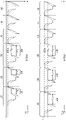
- Fig. 2 is a pressure-time diagram illustrating parts of a ventilation pattern according to an exemplary embodiment of the present disclosure.
- each phase of increased ventilation typically comprises at least two breaths of increased ventilation and each phase of decreased ventilation typically comprises at least two breaths of decreased ventilation.
- each phase of decreased ventilation typically comprises at least two breaths of decreased ventilation.
- only one breath of increased ventilation and one breath of decreased ventilation are illustrated in Fig. 2 .
- the continuous graph in the diagram represents the airway pressure (P aw ) of the ventilated patient, which pressure may be measured, e.g., by a pressure sensor located in the breathing circuit of the breathing apparatus 1.
- the dashed graph in the diagram represents the lung pressure (P alv ), sometimes referred to as the alveolar pressure, of the ventilated patient.
- P alv is closely related to P aw and can be estimated from P aw using known techniques, for example low-pass filtering techniques employing a pneumatic time constant derived from the resistance and compliance of the respiratory system of the patient.
- the ventilation pattern in Fig. 2 may be applied to the patient 3 by the breathing apparatus 1 illustrated in Fig. 1 when operated in a type of volume-controlled (VC) mode of operation incorporating IRPs to induce changes in the effective ventilation of the patient.
- VC volume-controlled
- the ventilation pattern comprises a first breath B1 of increased ventilation and a second breath B2 of decreased ventilation.
- the first breath B1 may, for instance, be the last of breath in a sequence of breaths of increased ventilation
- the second breath B2 may, for instance, be the first breath in a subsequent sequence of breaths of decreased ventilation.
- the breath B2 of decreased ventilation has a duration T B2 that is prolonged in relation to the duration T B1 of breath B1 of increased ventilation.
- the first breath B1 is a conventional volume-controlled breath in which a desired tidal volume of breathing gas is delivered to the lungs of the patient, typically at constant flow.
- the delivery of breathing gas to the lungs of the patient causes an increase in lung pressure from a PEEP level of a previous breath (not shown) to a higher end-inspiratory pressure level.
- the end-inspiratory lung pressure is the maximum lung pressure of the breathing cycle.
- the inspiration phase of breath B1 is further seen to comprise an end-inspiratory pause during which the end-inspiratory pressure level is maintained for a duration T EIP of the end-inspiratory paus.
- the end-inspiratory pause may be effectuated by the breathing apparatus through an occlusion manoeuvre, effectively preventing gas from flowing into or out of the breathing circuit.
- the expiration phase of breath B1 is commenced, e.g. through removal of the occlusion.
- the lung pressure of the patient drops from the maximum end-inspiratory pressure level towards the PEEP level.
- the PEEP level defines a minimum lung pressure of the breathing cycle.
- An end-inspiratory pause corresponding to the end-inspiratory pause in breath B1 of increased ventilation is then made before the expiration is commenced.
- the expiration phase of the prolonged breath B2 is identical to the expiration phase of breath B1 of increased ventilation.
- the IRP is characterised mainly by the duration of the IRP (T IRP ) and the intermediate pressure level P IRP at which it is initiated.
- the IRP may be effectuated by the breathing apparatus by carrying out an automatic occlusion manoeuvre effectively preventing flow into and out of the breathing circuit for the duration T IRP of the IRP.
- the duration T IRP of the IRP is typically predetermined and set to provide for a substantial increase in the level of expired CO2 content during the breath B2 of decreased ventilation compared to the level of expired CO2 content during the breath B1 of increased ventilation.
- the duration T IRP of the IRP is of the same order of magnitude as the duration T B1 of the entire breath B1 of increased ventilation.
- both the duration of the IRP and the duration of the breath B1 of increased ventilation are about 4 seconds.
- the duration of the entire prolonged breath B2 is typically about 8 seconds.
- the duration of the IRP and the duration of the breaths should be substantially shorter.
- all breaths of increased ventilation in the ventilation pattern have substantially the same length or duration.
- Each of the breaths of decreased ventilation in the ventilation pattern may, as discussed in more detail below, comprise a respective IRP.
- the duration of the IRP may be the same for all breaths of decreased ventilation, or it may vary in order to obtain a substantially steady state of expired CO2 during the phase of decreased ventilation, as also discussed in more detail below.
- the mean lung pressure P alv of the patient during the IRP should be in between the minimum and maximum lung pressure level of the breath in order for the proposed ventilation pattern to reduce variations in lung perfusion compared to ventilation patterns employing pre-inspiratory pauses or end-inspiratory pauses.
- the mean lung pressure of the patient during the IRP should correspond substantially to the mean lung pressure of the patient during breaths of increased ventilation.
- the lung pressure of the patient remains substantially constant during the IRP, which means that the intermediate pressure level P IRP at which the IRP is initiated should be in between the PEEP level and the end-inspiratory pressure of the prolonged breath, and should preferably correspond substantially to a mean lung pressure of the patient during breaths of increased ventilation.
- the value of P IRP may be fixed and predetermined, or it may be variable and dynamically calculated from pressure measurements obtained during previous breaths, for instance as the mean lung pressure of previous breaths of increased ventilation.
- P IRP may serve as a trigger value for triggering the IRP based on the estimated lung pressure of the patient. This means that the starting point in time for the IRP is not predetermined but dependent on the current lung pressure of the ventilated patient.
- the breathing apparatus initiates the IRP and prevents respiration by the patient for the duration T IRP of the IRP.
- the lung pressure may be readily estimated by the breathing apparatus, e.g., from measured airway pressure. This principle for triggering of the IRP is applicable in both VC mode and pressure-controlled (PC) operation mode of the breathing apparatus 1.
- the patient may be ventilated in accordance with a predetermined pressure profile (in PC mode) or a predetermined flow profile (in VC mode), where the point in time for initiation of the IRP is predetermined. Consequently, in this scenario, initiation of the IRP is time triggered and independent of the current lung pressure of the patient.
- the flow or pressure profile is parameterized to cause initiation of the IRP at a point in time where the lung pressure of the patient can be assumed to correspond substantially to a mean lung pressure of the patient during breaths of increased ventilation.
- Flow ⁇ i for t 0 ⁇ t ⁇ t 0 + t 1
- ⁇ i is a constant flow of the VC mode ventilation
- t 0 is the start time of the inspiration phase of the prolonged breath
- T IRP is the duration of the IRP
- T insp is the duration of the inspiration phase of the prolonged breath
- T EIP is the set
- Fig. 3 is a pressure-time diagram illustrating parts of a ventilation pattern according to another exemplary embodiment of the present disclosure. For illustrative purposes, only one breath of increased ventilation and one breath of decreased ventilation are illustrated. Like in Fig. 2 , the continuous graph represents airway pressure P aw and the dashed graph represents lung pressure P alv .
- the ventilation pattern in Fig. 3 may be applied to the patient 3 by the breathing apparatus 1 illustrated in Fig. 1 when operated in a type of pressure-controlled (PC) mode of operation incorporating IRPs to induce changes in the effective ventilation of the patient.
- PC pressure-controlled
- the ventilation pattern comprises a first breath B1 of increased ventilation and a second breath B2 of decreased ventilation.
- the first breath B1 may, for instance, be the last breath in a sequence of breaths of increased ventilation
- the second breath B2 may, for instance, be the first breath in a subsequent sequence of breaths of decreased ventilation.
- the breath B2 of decreased ventilation has a duration T B2 that is prolonged in relation to the duration T B1 of breath B1 of increased ventilation.
- the first breath B1 is a conventional pressure-controlled breath in which the pressure applied to the airways of the patient is increased from a PEEP pressure of a preceding breath to a set plateau pressure P plateau .
- the lung pressure P alv of the patient is seen to follow the airway pressure P aw with a slight delay.
- the plateau pressure is then maintained for the remains of a set duration T insp_B1 of the inspiration phase.
- the expiration phase of breath B1 is commenced by reducing the applied pressure to the PEEP level.
- the inspiration phase of the prolonged breath B2 is commenced by raising the applied pressure from the PEEP level of B1 (corresponding to a pre-inspiratory pressure of B2) to an intermediate pressure level P IRP that is higher than the PEEP level and lower than the plateau pressure P plateau .
- P IRP in accordance with the principles of the present disclosure is introduced, causing a decrease in the effective ventilation of the patient resulting in an increase in the level of expired CO2.
- P IRP should preferably correspond substantially to the mean lung pressure of the patient during phases of increased ventilation.
- the pressure is further increased to the plateau level P plateau in order to resume and complete the inspiration phase of the prolonged breath B2.
- the plateau pressure is maintained for the remains of a set duration T insp_B2 of the inspiration phase, whereafter expiration is initiated by lowering the applied pressure from the plateau pressure level to the PEEP level.
- the expiration phase of the prolonged breath B2 is identical to the expiration phase of breath B1 of increased ventilation.
- the breathing apparatus 1 can be said to operate in a mode of inspiratory bi-level airway pressure regulation as the airway pressure during inspiration is first regulated towards the intermediate pressure level P IRP , and then towards the final plateau pressure level P plateau .
- the breathing apparatus 1 can be said to operate in a mode of expiratory bi-level PEEP regulation as the PEEP level during a first part of expiration is maintained at a pressure level which may be regarded as a first and normal (non-elevated) PEEP level, and then, during a final part of expiration, at a pressure level which may be regarded as a second and elevated PEEP level.
- the intermediate pressure P IRP at which the IRP is initiated is higher than the normal PEEP and lower than the plateau pressure P plateau .
- the IRP of the present disclosure is a respiratory pause that is initiated at an intermediate pressure P IRP that is higher than a minimum lung pressure of the current breath, and lower than a maximum lung pressure of the current breath.
- the IRP is made during an inspiration phase of a breath and can thus be said to be an inspiratory IRP.
- the IRP may as well be an expiratory IRP that is made during an expiratory phase of a breath.
- expiratory IRPs may solve or mitigate the problem of varying lung perfusion during changes in effective ventilation.
- inspiratory IRPs may be advantageous compared to expiratory IRPs in that expiratory IRPs may jeopardize reliability and certainty in expiratory CO2 measurements.
- the expiratory phase should preferably be identical between breaths of increased and decreased ventilation.
- Fig. 4 illustrates an exemplary ventilation pattern wherein each phase of increased ventilation comprises three breaths B1', B1", B1′′′, each identical to the breath B1 in Fig. 2 , and each phase of decreased ventilation comprises three breaths B2', B2", B2′′′, each identical to the breath B2 in Fig. 2 .
- the ventilation pattern may be a cyclic ventilation pattern comprising alternating phases of decreased and increased ventilation to enable continuous monitoring of the hemodynamics of the ventilated subject. This means that the phase of decreased ventilation is immediately followed by a new phase of increased ventilation, which, in turn, is immediately followed by a new phase of decreased ventilation, and so on.
- the relatively short cycles of the ventilation pattern provides for quick response time in parameter determination.
- the determination of the one or more hemodynamic parameters is preferably made from flow and CO2 measurements using a non-invasive Fick technique.
- Fick-based methods for non-invasive determination of hemodynamic parameters may be used with no or a minimum of modification in order to calculate hemodynamic parameters such as Q and EPBF from measurements obtain during mechanical ventilation of a patient using the proposed ventilation pattern.
- the determination of the hemodynamic parameters may be made by the breathing apparatus itself or it may be made by external units, such as an external computer or a monitoring system configured to obtain flow and CO2 measurements related to the ongoing ventilation of the patient.
- external units such as an external computer or a monitoring system configured to obtain flow and CO2 measurements related to the ongoing ventilation of the patient.
- the breathing apparatus 1 may, in one exemplary embodiment, comprise at least one flow sensor 27 for measuring at least an expiratory flow of expiration gas exhaled by the patient 3, and at least one CO2 sensor 29 for measuring the CO2 content of at least the expiration gas exhaled by the patient.
- the control computer 13 may be configured to determine the at least one hemodynamic parameter from flow and CO2 measurements obtained during an analysed sequence of breaths during which the patient is ventilated using the proposed ventilation pattern.
- the flow and CO2 sensors 27, 29 are configured to measure also inspiratory flow and CO2 content which, in some circumstances, may be advantageously used together with expiratory flow and CO2 measurements in the determination of hemodynamic parameters.
- the flow sensor 27 and the CO2 sensor 29 form parts of a capnograph 31 configured for volumetric capnography measurements.
- the capnograph 31 is arranged in the proximity of the airways opening of the patient 3, namely in the common line 9 of the breathing circuit in which it is exposed to all gas exhaled and inhaled by the patient 3.
- the capnograph 31 is connected to the breathing apparatus 1 via a wired or wireless connection 33, and configured to transmit the flow and CO2 measurements to the ventilator for further processing by the processing unit 21 of the breathing apparatus.
- the breathing apparatus 1 is preferably configured to generate a volumetric capnogram 35 from the flow and CO2 measurements received from the capnograph 31, and, additionally, to display the volumetric capnogram 35 on a display 37 of the ventilator.
- F A CO2 n may be measured by the CO2 sensor 29 while C A CO2 n and VTCO2 may be directly calculated from F A CO2 n , the tidal volume of breath n (VT n ), and a known deadspace volume, as well known in the art, leaving EPBF, CvCO2 and ELV as unknown physiological parameters to be determined.
- Equation 1 is analogous to equation 1 in EP2641536 by the same applicant, disclosing a non-invasive and continuous method for simultaneous determination of ELV, cardiac output and CvCO2.
- equation 1 in EP2641536 uses the quantities CaCO2 (CO2 concentration or content per volume unit in arterial blood) and Q (cardiac output) whereas equation 1 above uses the quantities C A CO2 and EPBF.
- EPBF corresponds to cardiac output minus the intra-pulmonary shunt
- C A CO2 relates to CaCO2 in accordance with the equation:
- C A CO2 CaCO2-(CvCO2-CaCO2)*Qs/EPBF, where Qs is the shunt flow and CvCO2 is the CO2 concentration in the shunt flow (corresponding to the CO2 concentration in venous blood).
- Qs is the shunt flow
- CvCO2 is the CO2 concentration in the shunt flow (corresponding to the CO2 concentration in venous blood).
- the analysed sequence of breaths N comprises more than three breaths (i.e when N>3), this becomes an overdetermined system of equations and the unknown parameter triplet ⁇ ELV, EPBF ⁇ CvCO 2 , EPBF ⁇ and hence the physiological parameters ELV, EPBF, and CvCO 2 can be determined by finding an approximate solution to the overdetermined system of equation.
- the approximate solution to an overdetermined system of equations can be calculated in different ways, e.g. using the method of least squares. The solution to the overdetermined system of equations will depend on the correlation of the parameters ⁇ F A CO2, C A CO2 and VTCO2 in the respiratory cycles of the analyses sequence of respiratory cycles.
- the control computer 13 of the breathing apparatus 1 may for example be configured to calculate an approximate solution for the parameter triplet ⁇ ELV, EPBF ⁇ CvCO 2 , EBBF ⁇ by minimizing the error
- the control computer 13 may determine approximate values of ELV, EPBF, CvCO2, and Q from flow and CO2 measurements obtained for an analysed sequence of breaths during which the patient 3 is ventilated using the proposed ventilation pattern causing the level of expired CO2 to vary during the analysed sequence of breaths while improving parameter determination by minimizing variations in lung perfusion during the measurement period.
- the ventilation pattern is preferably a cyclic ventilation pattern and the parameters are preferably determined by the control computer 13 on a breath-by-breath basis.
- the number of breaths in said analysed sequence of breaths corresponds to the number of breaths in each cycle of the cyclic ventilation pattern.
- the ventilation pattern should preferably be adapted to provide for a desired overall ventilation of the subject. Therefore, the breaths of increased ventilation and the breaths of decreased ventilation may be adapted to provide for a desired mean ventilation of the patient, e.g. in terms of minute volume and mean airway pressure.
- the breaths of increased ventilation are hyperventilated breaths and the breaths of decreased ventilation are hypoventilated breaths.
- the total ventilation over time can be made to correspond to a desired baseline ventilation of the subject.
- phases of increased and decreased ventilation should not be construed as being limited to phases of ventilation that are increased and decreased in relation to baseline (normal) ventilation. Instead, it should be understood that in the context of this application, a phase of decreased ventilation is a phase in which ventilation is decreased compared to a phase of increased ventilation, and vice versa.
- embodiments wherein the level of ventilation in the phase of increased ventilation or the level of ventilation in the phase of decreased ventilation corresponds to a baseline level of ventilation are also encompassed by the present disclosure.
- the ventilation pattern may further be adapted to employ the technique of forced steady state, as described in more detail in WO2017/105304 . This is advantageous in that the determination of the hemodynamic parameters can be made using a ventilation pattern that is short in duration while still allowing the parameters to be determined with a high degree of certainty using non-complex algorithms.
- each phase of decreased ventilation may comprise at least a first breath for generating a substantial change in the level of CO2 expired by the patient 3, and at least a second breath, following the at least first breath, for causing the level of expired CO2 to assume a substantially steady state level within the phase of decreased ventilation, i.e. during at least two breaths in said phase of decreased ventilation.
- each phase of increased ventilation may comprise at least a first breath for generating a substantial and opposite change in the level of CO2 expired by the patient 3, and at least a second breath, following the at least first breath, for causing the level of expired CO2 to assume a new substantially steady state level within the phase of increased ventilation (i.e. during at least two breaths in the phase of increased ventilation).
- the substantial change in the level of expired CO2 is caused by changing the duration and/or volume of the at least one first breath with respect to a preceding breath, and the level of expired CO2 is caused to assume a steady state in the phase of decreased and/or increased ventilation by changing the duration and/or volume of the at least one second breath with respect to the duration and/or volume of the at least one first breath.
- control computer 13 of the breathing apparatus in Fig. 1 may be configured to cause any or both of the substantial change in the level of CO2 and the subsequent change for causing the level of CO2 to reach a substantially steady state within the phase of decreased and/or increased ventilation by introducing, removing or altering the duration of an IRP.
- a substantial increase in expired CO2 may be caused through the introduction of an IRP or the prolongation of an IRP in relation to any IRP of a preceding breath. This corresponds to the scenario illustrated in Fig. 2 where the transition from a phase of increased ventilation to a phase of decreased ventilation is initiated by introducing an IRP into breath B2.
- a substantial decrease in expired CO2 may be caused through the removal of an IRP or, potentially, even the shortening of an IRP in relation to any IRP of a preceding breath.
- the substantially steady state within the respective phases of decreased and increased ventilation may also be caused by introducing, removing or altering the duration of an IRP.
- a substantially steady state within a phase of decreased ventilation may be reached by shortening the IRP of a second breath of decreased ventilation in relation to the IRP of a first breath of decreased ventilation.
- a substantially steady state within a phase of increased ventilation may be reached by introducing a short IRP into a second breath of increased ventilation, following a first breath of increased ventilation with no IRP.
- Fig. 5 illustrates an exemplary ventilation pattern employing the forced steady-state technique by being adapted to cause the level of expired CO2 to reach a substantially steady state within the phase of decreased ventilation.
- the ventilation pattern in Fig. 5 includes a phase of increased ventilation comprising three breaths B1', B1", B1′′′ of increased ventilation, and a phase of decreased ventilation comprising three breaths B2', B2", B2'" of decreased ventilation.
- the breaths B1', B1", B1′′′ of increased ventilation are identical to the breaths of increased ventilation in Fig. 4 .
- the breaths of decreased ventilation, B2', B2", B2′′′ differ from the breaths of decreased ventilation in Fig.
- the first breath B2' of decreased ventilation is seen to comprise a relatively long IRP (having a duration T IRP' ) in order to cause a substantial change in the level of expired CO2 compared to the level of expired CO2 in the last breath B1′′′ of increased ventilation.
- the duration T IRP" of the IRP is made substantially shorter than the duration T IRP' of the IRP of the first breath B2' of decreased ventilation.
- the IRP of the second breath B2" is shortened in order to prevent further increase in the level of expired CO2 and force the level of expired CO2 during the second breath B2" of decreased ventilation to correspond substantially to the level of expired CO2 during the first breath B2' of decreased ventilation.
- the third breath B2'" of decreased ventilation may comprise an IRP having a duration T IRP′′′ which may correspond to the duration T IRP" of the IRP of the second breath B2", or which may differ from any or both of the durations of the IRPs of the first breath B2' and the second breath B2".
- the duration T IRP′′′ of the IRP of the third breath B2'" of decreased ventilation is adapted to maintain the level of expired CO2 at the substantially constant level obtained during the first two breaths B2', B2" of decreased ventilation.
- That the level of expired CO2 assumes a substantially steady state during two breaths herein means that a measure of expired CO2 obtained during a first breath is substantially equal to a corresponding measure of expired CO2 obtained during a second breath.
- Said measure of expired CO2 may be any measure indicative of alveolar CO2 of the ventilated patient 3, e.g. a measure of the fraction of alveolar CO2 (F A CO2) or a measure of the partial pressure of alveolar CO2 (P A CO2), including but not limited to end-tidal fraction of alveolar CO2 (F et CO2) and end-tidal partial pressure of CO2 (P et CO2).
- the at least two breaths of the same phase of decreased or increased ventilation during which the level of expired CO2 assumes a substantially steady state may or may not be consecutive breaths. If the second breath B2" of decreased ventilation is or cannot be properly adapted to make the level of CO2 expired during the second breath correspond to the level of CO2 expired during the first breath B2' of decreased ventilation, the duration T IRP′′′ of the third breath B2'" of decreased ventilation may be adapted to make the level of CO2 expired during the third breath B2′′′ correspond to the level of CO2 expired during any of the first breath B2' or the second breath B2" of decreased ventilation.
- the exemplary ventilation pattern illustrated in Fig. 5 is adapted for forced steady state only within phases of decreased ventilation. Instead or in addition, it could be adapted for forced steady state within phases of increased ventilation. In certain circumstances, it may be possible to obtain a sufficient change in the level of expired CO2 between phases of increased and decreased ventilation while still obtaining substantially steady states of expired CO2 in both phases of increased and decreased ventilation by no other means than introduction, removal and/or alteration of the duration of IRPs. However, other ways of changing the duration and/or volume of breaths of increased ventilation may be required in order to reach a substantially steady state in the level of expired CO2 within phases of increased ventilation.
- steady state within phases of increased ventilation may, for example, be obtained by making the tidal volume of the first breath of increased ventilation bigger than the tidal volumes of subsequent breaths of increased ventilation. Notably, this would increase the mean lung pressure of the patient during phases of increased ventilation, which should be accounted for in the selection of suitable intermediate pressure level P IRP for the IRPs in breaths of decreased ventilation.
- the breathing apparatus 1 in Fig. 1 may be configured to ventilate the patient 3 using a ventilation pattern employing the above described technique of forced steady state, such as the ventilation pattern illustrated in Fig. 5 .
- the control computer 13 may be configured to determine EPBF, Q and/or CvCO2 only from breaths during which the level of expired CO2 assumes a substantially steady state, or to determine EPBF, Q and/or CvCO2 from a sequence of breaths in which breaths of substantially steady state are weighted more heavily than breaths of non-steady state, as described in more detail in WO2017/105304 .
- control computer 13 may determine ELV only from transient breaths in said sequence of analysed breaths (i.e., from breaths having different levels of expired CO2 content), or from a sequence of breaths in which transient breaths are weighted more heavily than breaths of steady state, preferably using the determined values of EPBF, Q and/or CvCO2.
- the ventilation pattern described herein may be an adaptive ventilation pattern that is automatically adapted based on measured parameters indicative of the response by the patient to the currently applied ventilation pattern.
- the control computer 13 of the breathing apparatus 1 may be configured to use a measure of expired CO2, e.g. measured by the CO2 sensor 29, as control parameter for feedback control of the duration of IRPs in the breaths of the ventilation pattern.
- the control computer 13 may be configured to use expired CO2 for feedback control of the duration of the IRPs in order to achieve a desired change in the level of expired CO2 in the transition between phases of increased and decreased ventilation, and/or to cause the level of expired CO2 to assume a substantially steady state within the phase of increased and/or decreased ventilation.
- control computer 13 may be configured to compare the level of expired CO2 in the first breath B2'of decreased ventilation with the level of expired CO2 in the second and subsequent breath B2" of decreased ventilation, and, if the level of expired CO2 in the second breath deviates from the level of expired CO2 in the first breath by more than a predetermined amount (indicating that no steady state has been reached between the first two breaths of decreased ventilation), to adjust the duration T IRP′′′ of the IRP of the third breath B2′′′ to make the level of CO2 expired during the third breath correspond to that expired during the second breath B2" (or the first breath B2').
- the IRP of the third breath could be shortened in relation to the IRP of the second breath if the level of expired CO2 is higher during the second breath B2" than during the first breath B2'.
- This way of dynamically altering the duration of IRPs based on measured CO2 content in expiration gases may ensure that a steady state of expired CO2 is reached within phases of decreased ventilation, or that a more constant steady-state level is reached, and so provide for an even more reliable determination of hemodynamic parameters.
- an additional effect of ventilating a patient using the proposed ventilation pattern incorporating inspiratory IRPs at intermediate pressure levels is that a new type of pulmonary stress index is made available at the bedside.
- the compliance of the respiratory system of the ventilated patient may be determined for two distinct parts of a single inspiration phase, namely a first part of inspiration taking place prior to initiation of the IRP and a second part of inspiration taking place after the IRP. In this way, it can be determined whether the respiratory system compliance increases or decreases during the course of inspiration. This determination may, in accordance with known principles of stress index analysis, be used in the assessment of pulmonary stress.
Landscapes
- Health & Medical Sciences (AREA)
- Emergency Medicine (AREA)
- Pulmonology (AREA)
- Engineering & Computer Science (AREA)
- Anesthesiology (AREA)
- Biomedical Technology (AREA)
- Heart & Thoracic Surgery (AREA)
- Hematology (AREA)
- Life Sciences & Earth Sciences (AREA)
- Animal Behavior & Ethology (AREA)
- General Health & Medical Sciences (AREA)
- Public Health (AREA)
- Veterinary Medicine (AREA)
- Measurement Of The Respiration, Hearing Ability, Form, And Blood Characteristics Of Living Organisms (AREA)
Claims (14)
- Computerprogramm zum Ändern einer effektiven Beatmung eines mit einer Beatmungsvorrichtung (1) verbundenen Individuums (3), wobei das Computerprogramm computerlesbaren Code umfasst, der bei Ausführung durch einen Steuercomputer (13) der Beatmungsvorrichtung bewirkt, dass die Beatmungsvorrichtung das Individuum unter Verwendung eines Belatmungsmusters beatmet, das mindestens eine Phase einer erhöhten Beatmung und mindestens eine Phase einer verringerten Beatmung umfasst, wobei die Phase der verringerten Beatmung mindestens einen verlängerten Atem (B2; B2'-B2‴), der eine Atempause (IRP) enthält, umfasst, gekennzeichnet durch Bewirken, dass die Atempause eingeleitet wird, wenn der Lungendruck (Palv) des Individuums zwischen einem minimalen Lungendruck und einem maximalen Lungendruck des Individuums während des verlängerten Atems liegt.
- Computerprogramm nach Anspruch 1, wobei die Atempause (IRP) bei einem Zwischendruckniveau (PIRP) eingeleitet wird, das höher ist als ein positives endexspiratorisches Druck (PEEP)-Niveau eines vorherigen Atems und niedriger als ein endinspiratorischer Druckniveau des verlängerten Atems.
- Computerprogramm nach Anspruch 1 oder 2, wobei das Zwischendruckniveau (PIRP) im Wesentlichen einem mittleren Lungendruck des Individuums während Atemzügen erhöhter Beatmung entspricht.
- Computerprogramm nach einem der vorhergehenden Ansprüche, wobei die Atempause (IRP) eine intrainspiratorische Pause einer Einatmungsphase des verlängerten Atems ist.
- Computerprogramm nach einem der vorhergehenden Ansprüche, wobei die Phase der verringerten Beatmung mindestens einen zweiten Atem (B2") enthält, der dem verlängerten Atem (B2') folgt, wobei der zweite Atem eine Atempause umfasst, die eingeleitet wird, wenn der Lungendruck (Palv) des Individuums zwischen einem minimalen Lungendruck und einem maximalen Lungendruck des Individuums während des zweiten Atems liegt, wobei die Dauer (TIRP") der Atempause des zweiten Atems (B2") kürzer ist als die Dauer (TIRP') der Atempause des verlängerten Atems (B2'), um zu bewirken, dass ein Niveau von ausgeatmetem CO2 einen im Wesentlichen stabilen Zustand innerhalb der Phase der verringerten Beatmung einnimmt.
- Computerprogramm nach einem der vorhergehenden Ansprüche, das ferner bewirkt, dass ein hämodynamischer Parameter, der sich auf die Hämodynamik des beatmeten Individuums (3) bezieht, nicht-invasiv bestimmt wird, basierend auf während der Beatmung des Individuums unter Verwendung des Beatmungsmusters erhaltenen Durchfluss- und CO2-Messungen.
- Computerprogramm nach Anspruch 6, wobei die Bestimmung unter Verwendung einer Fick-Technik auf CO2-Basis erfolgt.
- Beatmungsvorrichtung (1) zum Ändern einer effektiven Beatmung eines mit der Beatmungsvorrichtung verbundenen Individuums (3), umfassend einen Steuercomputer (13), der konfiguriert ist, um den Betrieb der Beatmungsvorrichtung derart zu steuern, dass das Individuum unter Verwendung eines Belatmungsmusters beatmet wird, das mindestens eine Phase einer erhöhten Beatmung und mindestens eine Phase einer verringerten Beatmung umfasst, wobei die Phase der verringerten Beatmung mindestens einen verlängerten Atem (B2; B2'-B2‴) umfasst, der eine Atempause (IRP) enthält, dadurch gekennzeichnet, dass der Steuercomputer (13) konfiguriert ist, um zu bewirken, dass die Atempause eingeleitet wird, wenn der Lungendruck (Palv) des Individuums zwischen einem minimalen Lungendruck und einem maximalen Lungendruck des Individuums während des verlängerten Atems liegt.
- Beatmungsvorrichtung (1) nach Anspruch 8, wobei der Steuercomputer (13) konfiguriert ist, um zu bewirken, dass die Atempause (IRP) bei einem Zwischendruckniveau (PIRP) eingeleitet wird, das höher ist als ein positives endexspiratorisches Druck (PEEP)-Niveau eines vorherigen Atems und niedriger als ein endinspiratorischer Druckniveau des verlängerten Atems.
- Beatmungsvorrichtung (1) nach Anspruch 8 oder 9, wobei das Zwischendruckniveau (PIRP) im Wesentlichen einem mittleren Lungendruck des Individuums während Atemzügen erhöhter Beatmung entspricht.
- Beatmungsvorrichtung (1) nach einem der Ansprüche 8 bis 10, wobei die Atempause (IRP) eine intrainspiratorische Pause einer Einatmungsphase des verlängerten Atems ist.
- Beatmungsvorrichtung (1) nach einem der Ansprüche 8 bis 11, wobei der Steuercomputer (13) konfiguriert ist, um zu bewirken, dass die Phase der verringerten Beatmung mindestens einen zweiten Atem (B2") umfasst, der dem verlängerten Atem (B2') folgt, wobei der zweite Atem eine Atempause umfasst, die eingeleitet wird, wenn der Lungendruck (Palv) des Individuums zwischen einem minimalen Lungendruck und einem maximalen Lungendruck des Individuums während des zweiten Atems liegt, wobei die Dauer (TIRP") der Atempause des zweiten Atems (B2") kürzer ist als die Dauer (TIRP') der Atempause des verlängerten Atems (B2'), um zu bewirken, dass ein Niveau von ausgeatmetem CO2 einen im Wesentlichen stabilen Zustand innerhalb der Phase der verringerten Beatmung einnimmt.
- Beatmungsvorrichtung (1) nach einem der Ansprüche 8 bis 12, ferner umfassend mindestens einen Durchflusssensor (27) zum Messen mindestens eines exspiratorischen Flusses von Exspirationsgas, das von dem Individuum (3) ausgeatmet wird, und mindestens einen CO2 -Sensor (29) zum Messen des CO2-Gehalts von zumindest dem von dem Individuum ausgeatmeten Exspirationsgas, wobei der Steuercomputer (13) konfiguriert ist, um nicht-invasiv einen hämodynamischen Parameter zu bestimmen, der sich auf die Hämodynamik des beatmeten Individuums bezieht, basierend auf Durchfluss- und CO2-Messungen, die während der Beatmung des Individuums erhalten wurden, unter Verwendung des Beatmungsmusters.
- Beatmungsvorrichtung (1) nach Anspruch 13, wobei die Bestimmung unter Verwendung einer Fick-Technik auf CO2-Basis erfolgt.
Applications Claiming Priority (1)
| Application Number | Priority Date | Filing Date | Title |
|---|---|---|---|
| PCT/SE2018/050606 WO2019240634A1 (en) | 2018-06-11 | 2018-06-11 | Ventilation pattern for hemodynamic parameter determination during mechanical ventilation |
Publications (2)
| Publication Number | Publication Date |
|---|---|
| EP3801716A1 EP3801716A1 (de) | 2021-04-14 |
| EP3801716B1 true EP3801716B1 (de) | 2022-09-21 |
Family
ID=62705640
Family Applications (1)
| Application Number | Title | Priority Date | Filing Date |
|---|---|---|---|
| EP18733363.8A Active EP3801716B1 (de) | 2018-06-11 | 2018-06-11 | Beatmungsmuster zur hämodynamischen parameterbestimmung während der mechanischen beatmung |
Country Status (4)
| Country | Link |
|---|---|
| US (1) | US12064552B2 (de) |
| EP (1) | EP3801716B1 (de) |
| CN (1) | CN112261964B (de) |
| WO (1) | WO2019240634A1 (de) |
Families Citing this family (3)
| Publication number | Priority date | Publication date | Assignee | Title |
|---|---|---|---|---|
| FR3106066B1 (fr) * | 2020-01-14 | 2021-12-10 | Air Liquide Medical Systems | Ventilateur médical avec affichage simultané de différentes pressions |
| CN113908389A (zh) * | 2021-09-08 | 2022-01-11 | 上海瑞鞍星医疗科技有限公司 | 具有治疗肺毛细血管功能障碍的呼吸机控制方法及呼吸机 |
| DE102021134348A1 (de) * | 2021-12-22 | 2023-06-22 | Drägerwerk AG & Co. KGaA | Verfahren und System mit einer Messvorrichtung und einer Analysevorrichtung zu einer Verarbeitung von Daten |
Family Cites Families (5)
| Publication number | Priority date | Publication date | Assignee | Title |
|---|---|---|---|---|
| US7135001B2 (en) * | 2001-03-20 | 2006-11-14 | Ric Investments, Llc | Rebreathing methods including oscillating, substantially equal rebreathing and nonrebreathing periods |
| EP1579882A1 (de) * | 2004-03-26 | 2005-09-28 | Stephan Dr. Böhm | Nichtinvasives Verfahren zur Optimierung der Beatmung atelektatischer Lungen |
| WO2013141766A1 (en) | 2012-03-21 | 2013-09-26 | Maquet Critical Care Ab | Method for continuous and non-invasive determination of effective lung volume and cardiac output |
| DE102012215662A1 (de) * | 2012-09-04 | 2014-03-06 | Hamilton Medical Ag | System zur automatisierten Einstellung eines durch eine Beatmungseinrichtung vorgegebenen Drucks |
| WO2017105304A1 (en) | 2015-12-16 | 2017-06-22 | Maquet Critical Care Ab | Ventilation pattern for non-invasive determination of elv, epbf, cardiac output and/or co2 content in venous blood |
-
2018
- 2018-06-11 EP EP18733363.8A patent/EP3801716B1/de active Active
- 2018-06-11 CN CN201880094447.6A patent/CN112261964B/zh active Active
- 2018-06-11 US US17/250,055 patent/US12064552B2/en active Active
- 2018-06-11 WO PCT/SE2018/050606 patent/WO2019240634A1/en not_active Ceased
Also Published As
| Publication number | Publication date |
|---|---|
| US20210220588A1 (en) | 2021-07-22 |
| US12064552B2 (en) | 2024-08-20 |
| CN112261964A (zh) | 2021-01-22 |
| WO2019240634A1 (en) | 2019-12-19 |
| CN112261964B (zh) | 2024-11-29 |
| EP3801716A1 (de) | 2021-04-14 |
Similar Documents
| Publication | Publication Date | Title |
|---|---|---|
| US11033700B2 (en) | Leak determination in a breathing assistance system | |
| US11027080B2 (en) | System and method for determining ventilator leakage during stable periods within a breath | |
| US8408203B2 (en) | System and methods for ventilating a patient | |
| US10085673B2 (en) | Method for continuous and non-invasive determination of effective lung volume and cardiac output | |
| US8272379B2 (en) | Leak-compensated flow triggering and cycling in medical ventilators | |
| US8424521B2 (en) | Leak-compensated respiratory mechanics estimation in medical ventilators | |
| EP3389752B1 (de) | Beatmungsmuster zur nichtinvasiven bestimmung von elv, epbf, herzzeitvolumen und/oder des co2-gehalts in venösem blut | |
| EP3801716B1 (de) | Beatmungsmuster zur hämodynamischen parameterbestimmung während der mechanischen beatmung | |
| JP6811892B2 (ja) | 仮想圧力トリガ機構を介した換気装置のガス送出の開始 | |
| US11045105B2 (en) | Determination of cardiac output or effective pulmonary blood flow during mechanical ventilation | |
| US10894136B2 (en) | Capnotracking of cardiac output or effective pulmonary blood flow during mechanical ventilation | |
| CN114129840B (zh) | 用于自动设定呼吸机的额定频率的方法和设备 | |
| US20250288765A1 (en) | Medical device for ventilating a living being, process and computer program for operating a medical device |
Legal Events
| Date | Code | Title | Description |
|---|---|---|---|
| STAA | Information on the status of an ep patent application or granted ep patent |
Free format text: STATUS: UNKNOWN |
|
| STAA | Information on the status of an ep patent application or granted ep patent |
Free format text: STATUS: THE INTERNATIONAL PUBLICATION HAS BEEN MADE |
|
| PUAI | Public reference made under article 153(3) epc to a published international application that has entered the european phase |
Free format text: ORIGINAL CODE: 0009012 |
|
| STAA | Information on the status of an ep patent application or granted ep patent |
Free format text: STATUS: REQUEST FOR EXAMINATION WAS MADE |
|
| 17P | Request for examination filed |
Effective date: 20201111 |
|
| AK | Designated contracting states |
Kind code of ref document: A1 Designated state(s): AL AT BE BG CH CY CZ DE DK EE ES FI FR GB GR HR HU IE IS IT LI LT LU LV MC MK MT NL NO PL PT RO RS SE SI SK SM TR |
|
| AX | Request for extension of the european patent |
Extension state: BA ME |
|
| DAV | Request for validation of the european patent (deleted) | ||
| DAX | Request for extension of the european patent (deleted) | ||
| GRAP | Despatch of communication of intention to grant a patent |
Free format text: ORIGINAL CODE: EPIDOSNIGR1 |
|
| STAA | Information on the status of an ep patent application or granted ep patent |
Free format text: STATUS: GRANT OF PATENT IS INTENDED |
|
| INTG | Intention to grant announced |
Effective date: 20220413 |
|
| GRAS | Grant fee paid |
Free format text: ORIGINAL CODE: EPIDOSNIGR3 |
|
| GRAA | (expected) grant |
Free format text: ORIGINAL CODE: 0009210 |
|
| STAA | Information on the status of an ep patent application or granted ep patent |
Free format text: STATUS: THE PATENT HAS BEEN GRANTED |
|
| AK | Designated contracting states |
Kind code of ref document: B1 Designated state(s): AL AT BE BG CH CY CZ DE DK EE ES FI FR GB GR HR HU IE IS IT LI LT LU LV MC MK MT NL NO PL PT RO RS SE SI SK SM TR |
|
| REG | Reference to a national code |
Ref country code: GB Ref legal event code: FG4D |
|
| REG | Reference to a national code |
Ref country code: CH Ref legal event code: EP |
|
| REG | Reference to a national code |
Ref country code: DE Ref legal event code: R096 Ref document number: 602018040895 Country of ref document: DE |
|
| REG | Reference to a national code |
Ref country code: IE Ref legal event code: FG4D |
|
| REG | Reference to a national code |
Ref country code: AT Ref legal event code: REF Ref document number: 1519653 Country of ref document: AT Kind code of ref document: T Effective date: 20221015 |
|
| REG | Reference to a national code |
Ref country code: LT Ref legal event code: MG9D |
|
| REG | Reference to a national code |
Ref country code: NL Ref legal event code: MP Effective date: 20220921 |
|
| PG25 | Lapsed in a contracting state [announced via postgrant information from national office to epo] |
Ref country code: SE Free format text: LAPSE BECAUSE OF FAILURE TO SUBMIT A TRANSLATION OF THE DESCRIPTION OR TO PAY THE FEE WITHIN THE PRESCRIBED TIME-LIMIT Effective date: 20220921 Ref country code: RS Free format text: LAPSE BECAUSE OF FAILURE TO SUBMIT A TRANSLATION OF THE DESCRIPTION OR TO PAY THE FEE WITHIN THE PRESCRIBED TIME-LIMIT Effective date: 20220921 Ref country code: NO Free format text: LAPSE BECAUSE OF FAILURE TO SUBMIT A TRANSLATION OF THE DESCRIPTION OR TO PAY THE FEE WITHIN THE PRESCRIBED TIME-LIMIT Effective date: 20221221 Ref country code: LV Free format text: LAPSE BECAUSE OF FAILURE TO SUBMIT A TRANSLATION OF THE DESCRIPTION OR TO PAY THE FEE WITHIN THE PRESCRIBED TIME-LIMIT Effective date: 20220921 Ref country code: LT Free format text: LAPSE BECAUSE OF FAILURE TO SUBMIT A TRANSLATION OF THE DESCRIPTION OR TO PAY THE FEE WITHIN THE PRESCRIBED TIME-LIMIT Effective date: 20220921 Ref country code: FI Free format text: LAPSE BECAUSE OF FAILURE TO SUBMIT A TRANSLATION OF THE DESCRIPTION OR TO PAY THE FEE WITHIN THE PRESCRIBED TIME-LIMIT Effective date: 20220921 |
|
| REG | Reference to a national code |
Ref country code: AT Ref legal event code: MK05 Ref document number: 1519653 Country of ref document: AT Kind code of ref document: T Effective date: 20220921 |
|
| PG25 | Lapsed in a contracting state [announced via postgrant information from national office to epo] |
Ref country code: HR Free format text: LAPSE BECAUSE OF FAILURE TO SUBMIT A TRANSLATION OF THE DESCRIPTION OR TO PAY THE FEE WITHIN THE PRESCRIBED TIME-LIMIT Effective date: 20220921 Ref country code: GR Free format text: LAPSE BECAUSE OF FAILURE TO SUBMIT A TRANSLATION OF THE DESCRIPTION OR TO PAY THE FEE WITHIN THE PRESCRIBED TIME-LIMIT Effective date: 20221222 |
|
| PG25 | Lapsed in a contracting state [announced via postgrant information from national office to epo] |
Ref country code: SM Free format text: LAPSE BECAUSE OF FAILURE TO SUBMIT A TRANSLATION OF THE DESCRIPTION OR TO PAY THE FEE WITHIN THE PRESCRIBED TIME-LIMIT Effective date: 20220921 Ref country code: RO Free format text: LAPSE BECAUSE OF FAILURE TO SUBMIT A TRANSLATION OF THE DESCRIPTION OR TO PAY THE FEE WITHIN THE PRESCRIBED TIME-LIMIT Effective date: 20220921 Ref country code: PT Free format text: LAPSE BECAUSE OF FAILURE TO SUBMIT A TRANSLATION OF THE DESCRIPTION OR TO PAY THE FEE WITHIN THE PRESCRIBED TIME-LIMIT Effective date: 20230123 Ref country code: ES Free format text: LAPSE BECAUSE OF FAILURE TO SUBMIT A TRANSLATION OF THE DESCRIPTION OR TO PAY THE FEE WITHIN THE PRESCRIBED TIME-LIMIT Effective date: 20220921 Ref country code: CZ Free format text: LAPSE BECAUSE OF FAILURE TO SUBMIT A TRANSLATION OF THE DESCRIPTION OR TO PAY THE FEE WITHIN THE PRESCRIBED TIME-LIMIT Effective date: 20220921 Ref country code: AT Free format text: LAPSE BECAUSE OF FAILURE TO SUBMIT A TRANSLATION OF THE DESCRIPTION OR TO PAY THE FEE WITHIN THE PRESCRIBED TIME-LIMIT Effective date: 20220921 |
|
| PG25 | Lapsed in a contracting state [announced via postgrant information from national office to epo] |
Ref country code: SK Free format text: LAPSE BECAUSE OF FAILURE TO SUBMIT A TRANSLATION OF THE DESCRIPTION OR TO PAY THE FEE WITHIN THE PRESCRIBED TIME-LIMIT Effective date: 20220921 Ref country code: PL Free format text: LAPSE BECAUSE OF FAILURE TO SUBMIT A TRANSLATION OF THE DESCRIPTION OR TO PAY THE FEE WITHIN THE PRESCRIBED TIME-LIMIT Effective date: 20220921 Ref country code: IS Free format text: LAPSE BECAUSE OF FAILURE TO SUBMIT A TRANSLATION OF THE DESCRIPTION OR TO PAY THE FEE WITHIN THE PRESCRIBED TIME-LIMIT Effective date: 20230121 Ref country code: EE Free format text: LAPSE BECAUSE OF FAILURE TO SUBMIT A TRANSLATION OF THE DESCRIPTION OR TO PAY THE FEE WITHIN THE PRESCRIBED TIME-LIMIT Effective date: 20220921 |
|
| REG | Reference to a national code |
Ref country code: DE Ref legal event code: R097 Ref document number: 602018040895 Country of ref document: DE |
|
| PG25 | Lapsed in a contracting state [announced via postgrant information from national office to epo] |
Ref country code: NL Free format text: LAPSE BECAUSE OF FAILURE TO SUBMIT A TRANSLATION OF THE DESCRIPTION OR TO PAY THE FEE WITHIN THE PRESCRIBED TIME-LIMIT Effective date: 20220921 Ref country code: AL Free format text: LAPSE BECAUSE OF FAILURE TO SUBMIT A TRANSLATION OF THE DESCRIPTION OR TO PAY THE FEE WITHIN THE PRESCRIBED TIME-LIMIT Effective date: 20220921 |
|
| P01 | Opt-out of the competence of the unified patent court (upc) registered |
Effective date: 20230526 |
|
| PLBE | No opposition filed within time limit |
Free format text: ORIGINAL CODE: 0009261 |
|
| STAA | Information on the status of an ep patent application or granted ep patent |
Free format text: STATUS: NO OPPOSITION FILED WITHIN TIME LIMIT |
|
| PG25 | Lapsed in a contracting state [announced via postgrant information from national office to epo] |
Ref country code: DK Free format text: LAPSE BECAUSE OF FAILURE TO SUBMIT A TRANSLATION OF THE DESCRIPTION OR TO PAY THE FEE WITHIN THE PRESCRIBED TIME-LIMIT Effective date: 20220921 |
|
| 26N | No opposition filed |
Effective date: 20230622 |
|
| PG25 | Lapsed in a contracting state [announced via postgrant information from national office to epo] |
Ref country code: SI Free format text: LAPSE BECAUSE OF FAILURE TO SUBMIT A TRANSLATION OF THE DESCRIPTION OR TO PAY THE FEE WITHIN THE PRESCRIBED TIME-LIMIT Effective date: 20220921 |
|
| PG25 | Lapsed in a contracting state [announced via postgrant information from national office to epo] |
Ref country code: MC Free format text: LAPSE BECAUSE OF FAILURE TO SUBMIT A TRANSLATION OF THE DESCRIPTION OR TO PAY THE FEE WITHIN THE PRESCRIBED TIME-LIMIT Effective date: 20220921 |
|
| PG25 | Lapsed in a contracting state [announced via postgrant information from national office to epo] |
Ref country code: MC Free format text: LAPSE BECAUSE OF FAILURE TO SUBMIT A TRANSLATION OF THE DESCRIPTION OR TO PAY THE FEE WITHIN THE PRESCRIBED TIME-LIMIT Effective date: 20220921 |
|
| REG | Reference to a national code |
Ref country code: CH Ref legal event code: PL |
|
| REG | Reference to a national code |
Ref country code: BE Ref legal event code: MM Effective date: 20230630 |
|
| GBPC | Gb: european patent ceased through non-payment of renewal fee |
Effective date: 20230611 |
|
| PG25 | Lapsed in a contracting state [announced via postgrant information from national office to epo] |
Ref country code: LU Free format text: LAPSE BECAUSE OF NON-PAYMENT OF DUE FEES Effective date: 20230611 |
|
| REG | Reference to a national code |
Ref country code: IE Ref legal event code: MM4A |
|
| PG25 | Lapsed in a contracting state [announced via postgrant information from national office to epo] |
Ref country code: LU Free format text: LAPSE BECAUSE OF NON-PAYMENT OF DUE FEES Effective date: 20230611 |
|
| PG25 | Lapsed in a contracting state [announced via postgrant information from national office to epo] |
Ref country code: IE Free format text: LAPSE BECAUSE OF NON-PAYMENT OF DUE FEES Effective date: 20230611 |
|
| PG25 | Lapsed in a contracting state [announced via postgrant information from national office to epo] |
Ref country code: IE Free format text: LAPSE BECAUSE OF NON-PAYMENT OF DUE FEES Effective date: 20230611 Ref country code: GB Free format text: LAPSE BECAUSE OF NON-PAYMENT OF DUE FEES Effective date: 20230611 Ref country code: CH Free format text: LAPSE BECAUSE OF NON-PAYMENT OF DUE FEES Effective date: 20230630 |
|
| PG25 | Lapsed in a contracting state [announced via postgrant information from national office to epo] |
Ref country code: IT Free format text: LAPSE BECAUSE OF FAILURE TO SUBMIT A TRANSLATION OF THE DESCRIPTION OR TO PAY THE FEE WITHIN THE PRESCRIBED TIME-LIMIT Effective date: 20220921 Ref country code: BE Free format text: LAPSE BECAUSE OF NON-PAYMENT OF DUE FEES Effective date: 20230630 |
|
| PG25 | Lapsed in a contracting state [announced via postgrant information from national office to epo] |
Ref country code: BG Free format text: LAPSE BECAUSE OF FAILURE TO SUBMIT A TRANSLATION OF THE DESCRIPTION OR TO PAY THE FEE WITHIN THE PRESCRIBED TIME-LIMIT Effective date: 20220921 |
|
| PG25 | Lapsed in a contracting state [announced via postgrant information from national office to epo] |
Ref country code: BG Free format text: LAPSE BECAUSE OF FAILURE TO SUBMIT A TRANSLATION OF THE DESCRIPTION OR TO PAY THE FEE WITHIN THE PRESCRIBED TIME-LIMIT Effective date: 20220921 |
|
| PGFP | Annual fee paid to national office [announced via postgrant information from national office to epo] |
Ref country code: DE Payment date: 20250520 Year of fee payment: 8 |
|
| PGFP | Annual fee paid to national office [announced via postgrant information from national office to epo] |
Ref country code: FR Payment date: 20250520 Year of fee payment: 8 |
|
| PG25 | Lapsed in a contracting state [announced via postgrant information from national office to epo] |
Ref country code: CY Free format text: LAPSE BECAUSE OF FAILURE TO SUBMIT A TRANSLATION OF THE DESCRIPTION OR TO PAY THE FEE WITHIN THE PRESCRIBED TIME-LIMIT; INVALID AB INITIO Effective date: 20180611 |
|
| PG25 | Lapsed in a contracting state [announced via postgrant information from national office to epo] |
Ref country code: HU Free format text: LAPSE BECAUSE OF FAILURE TO SUBMIT A TRANSLATION OF THE DESCRIPTION OR TO PAY THE FEE WITHIN THE PRESCRIBED TIME-LIMIT; INVALID AB INITIO Effective date: 20180611 |
|
| PG25 | Lapsed in a contracting state [announced via postgrant information from national office to epo] |
Ref country code: TR Free format text: LAPSE BECAUSE OF FAILURE TO SUBMIT A TRANSLATION OF THE DESCRIPTION OR TO PAY THE FEE WITHIN THE PRESCRIBED TIME-LIMIT Effective date: 20220921 |