EP3801644B1 - Systeme und verfahren zur intelligenten desinfektion von desinfektionsumgebungen mittels verwendung von ultraviolettem licht - Google Patents
Systeme und verfahren zur intelligenten desinfektion von desinfektionsumgebungen mittels verwendung von ultraviolettem licht Download PDFInfo
- Publication number
- EP3801644B1 EP3801644B1 EP19745385.5A EP19745385A EP3801644B1 EP 3801644 B1 EP3801644 B1 EP 3801644B1 EP 19745385 A EP19745385 A EP 19745385A EP 3801644 B1 EP3801644 B1 EP 3801644B1
- Authority
- EP
- European Patent Office
- Prior art keywords
- patient
- light
- room
- data
- patient room
- Prior art date
- Legal status (The legal status is an assumption and is not a legal conclusion. Google has not performed a legal analysis and makes no representation as to the accuracy of the status listed.)
- Active
Links
Images



Classifications
-
- A—HUMAN NECESSITIES
- A61—MEDICAL OR VETERINARY SCIENCE; HYGIENE
- A61L—METHODS OR APPARATUS FOR STERILISING MATERIALS OR OBJECTS IN GENERAL; DISINFECTION, STERILISATION OR DEODORISATION OF AIR; CHEMICAL ASPECTS OF BANDAGES, DRESSINGS, ABSORBENT PADS OR SURGICAL ARTICLES; MATERIALS FOR BANDAGES, DRESSINGS, ABSORBENT PADS OR SURGICAL ARTICLES
- A61L2/00—Disinfection or sterilisation of materials or objects, in general; Accessories therefor
- A61L2/02—Disinfection or sterilisation of materials or objects, in general; Accessories therefor using physical processes
- A61L2/08—Radiation
- A61L2/10—Ultraviolet [UV] radiation
-
- A—HUMAN NECESSITIES
- A61—MEDICAL OR VETERINARY SCIENCE; HYGIENE
- A61L—METHODS OR APPARATUS FOR STERILISING MATERIALS OR OBJECTS IN GENERAL; DISINFECTION, STERILISATION OR DEODORISATION OF AIR; CHEMICAL ASPECTS OF BANDAGES, DRESSINGS, ABSORBENT PADS OR SURGICAL ARTICLES; MATERIALS FOR BANDAGES, DRESSINGS, ABSORBENT PADS OR SURGICAL ARTICLES
- A61L2/00—Disinfection or sterilisation of materials or objects, in general; Accessories therefor
- A61L2/24—Apparatus using programmed or automatic operation
-
- A—HUMAN NECESSITIES
- A61—MEDICAL OR VETERINARY SCIENCE; HYGIENE
- A61L—METHODS OR APPARATUS FOR STERILISING MATERIALS OR OBJECTS IN GENERAL; DISINFECTION, STERILISATION OR DEODORISATION OF AIR; CHEMICAL ASPECTS OF BANDAGES, DRESSINGS, ABSORBENT PADS OR SURGICAL ARTICLES; MATERIALS FOR BANDAGES, DRESSINGS, ABSORBENT PADS OR SURGICAL ARTICLES
- A61L9/00—Disinfection, sterilisation or deodorisation of air
- A61L9/16—Disinfection, sterilisation or deodorisation of air using physical phenomena
- A61L9/18—Radiation
- A61L9/20—Ultraviolet radiation
-
- A—HUMAN NECESSITIES
- A61—MEDICAL OR VETERINARY SCIENCE; HYGIENE
- A61L—METHODS OR APPARATUS FOR STERILISING MATERIALS OR OBJECTS IN GENERAL; DISINFECTION, STERILISATION OR DEODORISATION OF AIR; CHEMICAL ASPECTS OF BANDAGES, DRESSINGS, ABSORBENT PADS OR SURGICAL ARTICLES; MATERIALS FOR BANDAGES, DRESSINGS, ABSORBENT PADS OR SURGICAL ARTICLES
- A61L2103/00—Materials or objects being the target of disinfection or sterilisation
- A61L2103/05—Living organisms or biological materials
-
- A—HUMAN NECESSITIES
- A61—MEDICAL OR VETERINARY SCIENCE; HYGIENE
- A61L—METHODS OR APPARATUS FOR STERILISING MATERIALS OR OBJECTS IN GENERAL; DISINFECTION, STERILISATION OR DEODORISATION OF AIR; CHEMICAL ASPECTS OF BANDAGES, DRESSINGS, ABSORBENT PADS OR SURGICAL ARTICLES; MATERIALS FOR BANDAGES, DRESSINGS, ABSORBENT PADS OR SURGICAL ARTICLES
- A61L2103/00—Materials or objects being the target of disinfection or sterilisation
- A61L2103/75—Room floors or walls
-
- A—HUMAN NECESSITIES
- A61—MEDICAL OR VETERINARY SCIENCE; HYGIENE
- A61L—METHODS OR APPARATUS FOR STERILISING MATERIALS OR OBJECTS IN GENERAL; DISINFECTION, STERILISATION OR DEODORISATION OF AIR; CHEMICAL ASPECTS OF BANDAGES, DRESSINGS, ABSORBENT PADS OR SURGICAL ARTICLES; MATERIALS FOR BANDAGES, DRESSINGS, ABSORBENT PADS OR SURGICAL ARTICLES
- A61L2202/00—Aspects relating to methods or apparatus for disinfecting or sterilising materials or objects
- A61L2202/10—Apparatus features
- A61L2202/14—Means for controlling sterilisation processes, data processing, presentation and storage means, e.g. sensors, controllers, programs
-
- A—HUMAN NECESSITIES
- A61—MEDICAL OR VETERINARY SCIENCE; HYGIENE
- A61L—METHODS OR APPARATUS FOR STERILISING MATERIALS OR OBJECTS IN GENERAL; DISINFECTION, STERILISATION OR DEODORISATION OF AIR; CHEMICAL ASPECTS OF BANDAGES, DRESSINGS, ABSORBENT PADS OR SURGICAL ARTICLES; MATERIALS FOR BANDAGES, DRESSINGS, ABSORBENT PADS OR SURGICAL ARTICLES
- A61L2209/00—Aspects relating to disinfection, sterilisation or deodorisation of air
- A61L2209/10—Apparatus features
- A61L2209/11—Apparatus for controlling air treatment
- A61L2209/111—Sensor means, e.g. motion, brightness, scent, contaminant sensors
-
- Y—GENERAL TAGGING OF NEW TECHNOLOGICAL DEVELOPMENTS; GENERAL TAGGING OF CROSS-SECTIONAL TECHNOLOGIES SPANNING OVER SEVERAL SECTIONS OF THE IPC; TECHNICAL SUBJECTS COVERED BY FORMER USPC CROSS-REFERENCE ART COLLECTIONS [XRACs] AND DIGESTS
- Y02—TECHNOLOGIES OR APPLICATIONS FOR MITIGATION OR ADAPTATION AGAINST CLIMATE CHANGE
- Y02B—CLIMATE CHANGE MITIGATION TECHNOLOGIES RELATED TO BUILDINGS, e.g. HOUSING, HOUSE APPLIANCES OR RELATED END-USER APPLICATIONS
- Y02B20/00—Energy efficient lighting technologies, e.g. halogen lamps or gas discharge lamps
- Y02B20/40—Control techniques providing energy savings, e.g. smart controller or presence detection
Definitions
- Building systems may be used to control environmental conditions in buildings. Such building systems may benefit from improvements.
- WO 2011/072087 A1 discloses an UV hard-surface disinfection system (10) comprising multiple UV light towers (200) that can be placed in several areas of a room and a cart (100) for loading and unloading said towers.
- the cart comprises a handle (130) and a control panel (140) including a display (142).
- the control panel (140) may be used to upload data to a hospital information system regarding the sanitization of a given room.
- the control panel (140) has communications ability with a "LMS" system, which is a scanner system to evaluate distance and occupancy for mapping rooms.
- the towers (200) each comprise a cap assembly (300) housing a safety sensor (302, 303) like a motion detector that senses if a person has entered a room and disables the tower.
- the towers (200) each further comprise a communications module (304) configured to communicate with the cart (100).
- WO 2014/022717 A1 discloses a method for organizing the disinfection of one or more items contaminated with biological agent(s) comprising attaching a radio-frequency ID (RFID) tag to one or more items to be disinfected; exposing the tagged items to a disinfecting means for a period sufficient to disinfect the items; and obtaining a signal from the tagged item when disinfection is complete.
- RFID radio-frequency ID
- Further D2 discloses a method for organizing the disinfection of a designated space like a hospital room.
- the disinfection means are ultra-violet light.
- the RFID tag communicates with the disinfection means.
- the RFID tag further communicates the initiation or completion of the cleaning or disinfection cycle to a computer or data warehouse.
- the signal from the tagged designated area is used to create a log of the cleaning or disinfecting history of each RFID tagged item (room) through the computer.
- the RFID tag is also attached to a patient and resets the status of the designated space for future disinfection. Cleaning personnel is alerted to clean a patient's room based on an entry in hospital medical records, that the respective patient left the hospital. Further, Real Time Location Systems (RTLS) are used to determine the physical proximity of active RFID tags.
- RTLS Real Time Location Systems
- WO 2015/026407 A1 discloses a sterilization system consisting of an emitter subsystem consisting of a mobile emitter (10) and a central computer (11), a sensing subsystem consisting of UV-sensors (21-24), a door sensor (30), a remote control (40) and a data logging subsystem.
- the computer (11) communicates with the door sensor (30), and if the door being monitored by the door sensor (30) is opened during a disinfection cycle the lamps are immediately turned off to prevent injury. Based on readings of the UV-sensors (21-24) an estimated time to completion is calculated by the computer (11). Pathogens being treated for are tracked and reported. A desired UV dosage based on the disinfection level desired and the pathogen(s) to be killed is selected by a user to configure the job. Information about specific infections or diseases are entered into a data management system of a hospital and forwarded to the sterilization system.
- Disclosed implementations include systems, methods, devices, and logic that support intelligent disinfection of disinfection environments through use of ultra-violet (UV) lights.
- UV ultra-violet
- a method may be performed, executed, or otherwise carried out by a building automation system (BAS).
- the method may include accessing patient room data indicative of a state of a patient room of a patient and controlling operation of a UV light to disinfect the patient room based on the patient room data.
- BAS building automation system
- a system may include a disinfection environment tracking engine and a UV light control engine.
- the disinfection environment tracking engine may be configured to access patient room data indicative of a state of a patient room of a patient; access medical data of the patient, the medical data of the patient specifying a medical condition of the patient; and access real-time location data of the patient.
- the UV light control engine may be configured to control operation of a UV light to disinfect the patient room based on the patient room data, the medical data of the patient, and the real-time location data of the patient.
- a non-transitory machine-readable medium may store instructions executable by a processor. When executed, the instructions may cause the processor or a building automation system to access patient room data indicative of a state of a patient room of a patient, the patient room data including an occupancy schedule for the patient room that indicates an unoccupied time period during which the patient does not occupy the room; access medical data of the patient, the medical data of the patient specifying a medical condition of the patient; and control operation of an UV light to disinfect the patient room based on the patient room data and the medical condition of the data, including by calibrating the UV light to account for a length of the unoccupied time period and a severity of the medical condition of the patient.
- UV light control features described herein cost savings may be achieved by optimizing operation parameters and activation times of controlled UV lights based on possible infection exposures, available disinfection times, patient-specific issues, etc. Further, the UV light control features described herein may track room occupancy in various ways, whether through occupancy sensors or patient real-time location data, automatically prioritizing safety by deactivating UV light operation upon detection that a disinfection environment is occupied.
- the building automation system 100 may support control of UV lights to disinfection environments of any number or type, e.g., patient rooms.
- the building automation system 100 may automate the activation and deactivation of UV lights to disinfect patient rooms (or any other disinfection environment) based on tracked environment data, which may include patient room occupancy, patient treatment schedules, medical conditions of patients, real-time location data of patients, any other user-configurable factors, or combinations thereof.
- the UV light control features described herein may provide disinfection of patient rooms with increased frequency or improved efficiency, which may result in a reduction in healthcare associated infections.
- the building automation system 100 shown in Figure 1 includes a disinfection environment tracking engine 108 and a UV light control engine 110.
- the building automation system 100 may implement the engines 108 and 110 (and components thereof) in various ways, for example as hardware and programming.
- the programming for the engines 108 and 110 may take the form of processor-executable instructions stored on a non-transitory machine-readable storage medium and the hardware for the engines 108 and 110 may include a processor to execute those instructions.
- a processor may take the form of single processor or multi-processor systems, and in some examples, the building automation system 100 implements multiple engines using the same computing system features or hardware components (e.g., a common processor or a common storage medium).
- the GUI 112 may include various components through which a user interfaces with the building automation system 100, such as a display, keyboard, mouse, touchscreen, etc.
- the disinfection environment tracking engine 108 may track a combination of building environment data and patient data relevant to a disinfection environment, and the UV light control engine 110 may control UV lights based on the tracked data.
- the disinfection environment tracking engine 108 may access patient room data indicative of a state of a patient room of a patient, medical data of the patient that specifies a medical condition of the patient, and real-time location data of the patient.
- the UV light control engine 110 may control operation of a UV light to disinfect the patient room based on the patient room data, the medical data of the patient, and the real-time location data of the patient.
- UV light control features presented herein are described via a patient room as an illustrative disinfection environment.
- a building automation system may consistently implement any of the described UV light control features for other disinfection environments as well, such as hospitality spaces (e.g., hotel rooms), food preparation facilities, cruise ships or other entertainment spaces, school classrooms, mixed office spaces, or any other environment in which UV lighting can be used for disinfection.
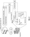
- Figure 2 shows an example of UV light control by a building automation system based on patient room data.
- the example shown in Figure 2 includes a building automation system 100 and an example disinfection environment depicted through a hospital 200. Although shown as physically remote to the hospital 200 in Figure 2 , in some examples the building automation system 100 is located within or as part of the hospital 200, whether in part or in whole.
- the building automation system 100 may provide control capabilities for various building elements of the hospital 200. Communications between the building automation system 100 and the hospital 200 may be supported by the network 202.
- the network 202 may take the form of any combination of one or more communication networks (or sub-networks) and supporting components by which the building automation system 100 may interact with specific building elements of the hospital 200. As such, the network 202 may include the Internet, proprietary backend communication systems, building device interfaces, and the like.
- the hospital 200 includes a patient room 210.
- the patient room 210 may be any physical space assigned to a patient, such as a hospital room, a treatment area, an allocated section of a hospital wing, etc. Accordingly, the patient 210 may include various building elements such as a bed, furniture, medical equipment or devices, lighting and blinds, tables, televisions, etc.
- the patient room 210 includes a patient bed, a couch, an occupancy sensor 211, a door 212, and a UV light 220.
- the UV light 220 may be any UV lighting device or building element that supports room disinfection. In that regard, the UV light 220 may provide sterilization capabilities through UV light emanation.
- Operation of the UV light 220 may be set through a UV light controller 230, which may include any circuitry that controls UV light 220 activation or deactivation, and support configuration of specific settings or characteristics of the emitted UV light (e.g., intensity, frequency, modulation, or any other UV light operation parameters).
- a UV light controller 230 may include any circuitry that controls UV light 220 activation or deactivation, and support configuration of specific settings or characteristics of the emitted UV light (e.g., intensity, frequency, modulation, or any other UV light operation parameters).
- the building automation system 100 may support automated operation of the UV light 220 in the patient room 210.
- the building automation system 100 may intelligently automate operation of the UV light 220 by communicating activation, parameter configuration, or deactivation instructions to the UV light controller 230.
- Such instructions may be issued by the building automation system 100 based on room occupancy schedules, other preset schedules, room occupancy states, and other factors, doing so while managing power and energy consumption of the UV light 220 (e.g., by identifying opportunities to reduce excess energy consumption for the disinfection process).
- the building automation system 100 may increase disinfection efficiency, optimize disinfection time, reduce building costs, or provide other benefits.
- the building automation system 100 controls operation of the UV light 220 based on occupancy of the patient room 210.
- the disinfection environment tracking engine 108 may acquire patient room data for the patient room 210, which may include any data indicative of a state of a patient room of a patient.
- the disinfection environment tracking engine 108 may access an occupancy status of the patient room from the occupancy sensor 211 in the patient room 210, whether by polling the occupancy sensor 211 or having occupancy status changes pushed from the occupancy sensor 211.
- the disinfection environment tracking engine 108 obtains an occupancy data 240 from the occupancy sensor 211, which may include data indicative of an occupancy state of the patient room 210.
- the building automation system 100 may activate the UV light 220 on an opportunistic basis at times (e.g., whenever) the patient room 210 is unoccupied. Based on the occupancy status of the patient room 210, the UV light control engine 110 may activate or deactivate the UV light 220, for instance by issuing activation or deactivation commands to the UV light controller 230. Activation or deactivation commands from the UV light control engine 110 may be included as control instructions, e.g., as depicted in Figure 2 as the control instructions 250. When the occupancy status indicates the patient room 210 is unoccupied, the UV light control engine 110 may activate the UV light 220 to disinfect the patient room.
- the UV light control engine 110 may deactivate the UV light 220. Accordingly, the UV light control engine 110 may activate the UV light 220 for room disinfection based on a present occupancy status of the patient room 210, e.g., as tracked by the occupancy sensor 211.
- the UV light control engine 110 may utilize a determined occupancy status in combination with other factors to control operation of the UV light 220. Some such examples are described next in Figure 3 with respect to patient schedules and real-time location data of a patient.
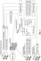
- Figure 3 shows an example of UV light control by a building automation system 100 based on patient room data and real-time location data of a patient.
- the disinfection environment tracking engine 108 may access disinfection environment or patient data from various sources to support intelligent control of the UV light 220.
- the hospital 200 may include various systems that track relevant patient data that the UV light control engine 110 may utilize to intelligently control UV lighting.
- the hospital 200 includes a patient information management system 311 and a patient real-time location system 312.
- the patient information management system 311 may store patient or other medical information of any type. Such patient/medical information may include electronic medical records of patients, disease and treatment history, admission and discharge records, prescription schedules, billing systems, procedural strategies, medical literature systems, disease databases, and more. To support such data warehousing, the patient information management system 311 may itself incorporate or include multiple disparate information systems, including as examples patient admission/discharge/transfer (ADT) systems, patient bed management systems (BMS), billing systems, registration and scheduling systems, occupancy schedules, and more.
- ADT patient admission/discharge/transfer
- BMS patient bed management systems
- billing systems registration and scheduling systems, occupancy schedules, and more.
- the UV light control engine 110 may operate the UV light 220 based on occupancy periods determined from occupancy schedules for the patient room 210.
- An occupancy schedule may refer to any data, listing, or other time-specification mechanism indicative of scheduling for the patient room 210 or relevant personnel that access the patient room 210 (e.g., the patient, medical staff, cleaning staff, visitors, etc.).
- Figure 3 shows one example of an occupancy schedule stored by the patient information management system 311 through a patient treatment schedule 320 for a patient, which the disinfection environment tracking engine 108 may retrieve for a patient assigned to the patient room 210.
- the UV light control engine 110 may analyze the patient treatment schedule 320 (or any other occupancy schedule) to determine occupied and unoccupied time periods for the patient room 210. For instance, the UV light control engine 110 may identify an assigned occupancy period from the patient information management system 311 during which a patient is assigned to the patient room 210 (e.g., via patient-to-room assignment data tracked by an ADT system or system module implemented by the patient information management system 311). During the assigned occupancy period, the UV light control engine 110 may extract time periods from the patient treatment schedule 320 during which the patient is scheduled for treatments or other medical activity outside of the patient room 210. The UV light control engine 110 may interpret any such scheduled time periods during which the patient is not scheduled to be present in the patient room 210 as unoccupied time periods for the patient room 210. Non-scheduled times may be interpreted by the UV light control engine 110 as occupied time periods during which the patient is scheduled or expected to be present in the patient room 210.
- the disinfection environment tracking engine 108 may access patient admission date/time data and a patient treatment schedule 320 from the patient information management system 311, specifically for the patient assigned to the patient room 210.
- the obtained patient information may indicate a patient admission time of 9:00am and a CT scan scheduled for 1:00pm-2:00pm on the same day.
- the UV light control engine 110 may determine the time period from 9:00am-1:00pm as an occupied time period and the time period from 1:00pm-2:00pm as an unoccupied time period for the patient room 210 based on the accessed patient treatment schedule 320.
- the UV light control engine 110 may parse or extract other unoccupied and occupied time periods from the patient treatment schedule 320.
- the UV light control engine 110 may control operation of the UV light 220 in the patient room 210 according to the unoccupied time periods extracted from the patient treatment schedule 320. During the determined unoccupied time periods, the UV light control engine 110 may activate the UV light 220 to disinfect the patient room 210 and deactivate the UV light 220 during the determined occupied time periods in the patient treatment schedule 320.
- a patient treatment schedule 320 is provided as an example source (e.g., occupancy schedule) from which the UV light control engine 110 may determine unoccupied time periods for the patient room 210
- other data sources may be likewise utilized to determine scheduled occupancy of the patient room 210.
- Other example sources include visitation hours to the patient room 210 (or the assigned patient), active visitations (e.g., when a visitor to the patient room 210 has been logged into a visitation system but not yet logged out), visitation schedules of medical staff (e.g., medical rounds or scheduled check-ins by nursing staff), cleaning staff schedules, etc., each for which the UV light control engine 110 may treat as an occupied time period for the room 210.
- the UV light control engine 110 may activate the UV light 220 and deactivate the UV light 220 during determined occupied time periods.
- the hospital 200 includes the patient real-time location (RTL) system 312 that stores patient RTL data 330.
- RTL real-time location
- the patient RTL system 312 may be implemented as a component or sub-system of the patient information management system 311.
- the disinfection environment tracking engine 108 may access the patient RTL data 330 for a patient assigned to the patient room 210, and the UV light control engine 110 may control operation of the UV light 220 based on the accessed patient RTL data 330.
- the UV light control engine 110 may automate activation of the UV light 220 during an unoccupied time period of the patient room 210 determined from the patient treatment schedule 320.
- the UV light control engine 110 may use the patient RTL data 330 (and additionally or alternatively use an occupancy status accessed from the occupancy sensor 211) to confirm that the patient is no longer present in the patient room 210 during the unoccupied time period.
- the UV light control engine 110 may confirm, via the patient RTL data 330, that the patient is not present in the patient room 210 during determined unoccupied time periods and, in response, activate the UV light 220 to disinfect the patient room.
- the UV light control engine 110 may activate the UV light 220 when a patient is at least a threshold distance away from the patient room 210 and deactivate the UV light 220 otherwise.
- the UV light control engine 110 may enforce an activation criteria that activates the UV light 220 only when the patient is at least 10 feet (or any other configurable distance) from the patient room 210. Responsive to a determination that the patient is less than 10 feet from the patient room 210 (e.g., returning to the patient room 210 after a scheduled treatment), the UV light control engine 110 may deactivate the UV light 220.
- the UV light control engine 110 may control operation of the UV light 220 to account for occupancy of the patient room 210.
- Actual or predicted (e.g., scheduled) occupancy may be determined in various ways, and the disinfection environment tracking engine 108 may access environment data, patient data, or any other data relevant or otherwise related to patient room occupancy.
- the UV light control engine 110 may utilize any of the described environment or patient data alone to control UV light operation. For instance, the UV light control engine 110 may use one of the occupancy status data extracted from the occupancy sensor 211, the unoccupied time periods extracted from the patient treatment schedule 320, or the patient location information tracked by the patient RTL data 330 as a sole condition or factor in activation and deactivation of the UV light 220. Alternatively, the UV light control engine 110 may use any of the accessed environment or patient data in combination to set automated activations of the UV light 220.
- the UV light control engine 110 may activate the UV light 220 upon confirmation that the patient room 210 is actually unoccupied, e.g., as confirmed via the occupancy sensor 211, the patient RTL data 330 or both.
- the UV light control engine 110 may opportunistically activate the UV light when the occupancy sensor 211 or patient RTL data 330 indicates the patient has left the patient room 210 or the patient room 210 is otherwise unoccupied.
- UV light control engine 110 may operate the UV light 220.
- a user e.g., a system administrator
- Such preset scheduling may correspond to a disinfection cycle or cleaning schedule set up by a medical facility.
- the UV light control engine 110 may effectuate the preset schedules by interfacing with the UV light controller 230 to activate the UV light 220 during the scheduled disinfection times.
- the UV light control engine 110 may override the activation based on a detected room occupancy, e.g., by immediately deactivating the UV light 220 responsive to a change in occupancy status as detected by the occupancy sensor 211, when the patient RTL data 330 indicates the patient is occupying the patient room 210, or is within a threshold distance from the patient room 210.
- the UV light control engine 110 may control operation of the UV light 220 by activating the UV light 220 responsive to a patient discharge or transfer.
- the disinfection environment tracking engine 108 may obtain discharge/transfer data from the patient information management system 311, which may specify a time when the patient assigned to the patient room 210 will be or has been discharged. Responsive to such a discharge/transfer determination, the UV light control engine 110 may schedule a UV light activation for the patient room 210 subsequent to the patient discharge/transfer (e.g., immediately subsequent or subsequent by a configured timing offset). Similarly as described above, the UV light control engine 110 may override the scheduled UV light activations upon detecting the patient room 210 is not unoccupied.
- the UV light control engine 110 triggers activation or deactivation the UV light 220 to disinfect the patient room 210.
- the UV light control engine 110 may control operation of the UV light 220 by setting any number of operation parameters of the UV light 220.
- the UV light control engine 110 may calibrate the light intensity of the UV light 220, otherwise modulate between different light intensities, or otherwise configure any operation parameter of the UV light 220.
- Parameter control, UV light activation and deactivation, and other control of the UV light 220 may be specified through control instructions sent by the UV light control engine 110, e.g., the control instructions 350 shown in Figure 3 .
- the UV light control engine 110 may configure operation of the UV light 220 according to a determined available disinfection period in which the patient room 210 is expected to or predicted to be unoccupied.
- the UV light control engine 110 may determine an available disinfection period based on accessed patient treatment schedules 320, for example, or according to any other schedule extraction techniques to identify preset times in which the patient is not scheduled to occupy the patient room 210. That is, the UV light control engine 110 may treat a determined unoccupied time period as an available disinfection period, though other ways to determine an available disinfection period are possible as well.
- the UV light control engine 110 may correlate a patient distance from the patient room 210 to a baseline (e.g., minimum) available disinfection period.
- the UV light control engine 110 may, for instance, convert a patient distance from the patient room 210 into a minimum available disinfection period based on the walking or transportation speed for a patient to return to the patient room 210.
- the UV light control engine 110 may determine an available disinfection period of at least 45 seconds when the patient is at least 100 feet from the patient room 210.
- the UV light control engine 110 may identify a particular available disinfection period based on the patient reaching or being at a particular location, e.g., as determined from the patient RTL data 330.
- the patient RTL data 330 may indicate the patient has reached a particular medical facility or room that requires a threshold amount of time for treatment (e.g., a MRI or CT scanning room, surgery room, delivery room, intensive care unit, etc.).
- the UV light control engine 110 may identify a correlated available disinfection period for the patient location, which may be specified in a correlation table or other configurable data structure.
- the UV light control engine 110 may adjust, customize, optimize, or intelligently automate operation of the UV light 220 based on determined available disinfection periods.
- the UV light control engine 110 may reduce the UV light intensity of the UV light 220 to reduce energy consumption during an available disinfection period of the patient room 210 (e.g., determined as an unoccupied time period) such that the UV light 220 is nonetheless effective to disinfect the patient room 210 during the available disinfection period.
- the UV light control engine 110 may deactivate the UV light 220 during the available disinfection period due to a disinfection cycle completing prior to the available disinfection period ending. Such a scenario may occur in which the patient is away from the patient room 210 for an extended period of time, upon which the UV light control engine 110 may reduce resource consumption and lighting costs by deactivating the UV light 220 once a sufficient amount of UV disinfection has occurred.
- UV light control engine 110 may activate or calibrate operation of the UV light 220 is patient medical conditions. Some examples of UV light control based on medical data of a patient are described next in Figure 4 .
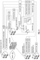
- Figure 4 shows an example of UV light control by a building automation system based on patient room data, real-time location data of a patient, and medical data of a patient.
- the disinfection environment tracking engine 108 accesses medical data of a patient, through which the UV light control engine 110 may activate or calibrate operation of the UV light 220 to disinfect the patient room 210.
- Example medical data accessible by the disinfection environment tracking engine 108 includes the current medical conditions(s) of a patient, infection capabilities of medical conditions, disease treatment methods, patient medical history, and more.
- the patient information management system 311 stores medical data in the form of electronic medical records 440 for a patient assigned to the patient room 210.
- the disinfection environment tracking engine 108 may retrieve the electronic medical records 440 for the patient and the UV light control engine 110 may adapt control of the UV light 220 for the patient room 210 based on the accessed electronic medical records 440.
- the UV light control engine 110 may tailor UV light operation for the patient room 210 to specifically address particular medical conditions or disease capabilities the patient room 210 is exposed to.
- the UV light control engine 110 may account for a contagiousness level or disease spreading capabilities of medical conditions that afflict the patient of the patient room 210.
- the UV light control engine 110 may increase the UV light intensity or activation UV disinfection times of the UV light 220 for severe or highly contagious medical conditions (e.g., airborne pathogens or life-threatening bacteria) or reduce UV operation parameters for medical conditions of lesser severity or contagiousness level (e.g., common cold, or non-infectious medical conditions).
- the UV light control engine 110 may access disinfection parameters for specific diseases, medical conditions, or ailments from medical databases.
- the center for disease control (CDC), research facilities, or other healthcare agencies may provide treatment recommendations or parameters for various medical conditions, and the building automation system 100 may access any such treatment parameters to calibrate the UV light 220.
- Such parameters may specify best-practices or recommended disinfection parameters, including UV light intensities and UV disinfection times to effectively eradicate infectious bacteria and diseases.
- the UV light control engine 110 may determine a disinfection time (or active disinfection time), which may refer to a baseline or minimum time period to activate the UV light 220 to disinfect the patient room 210. Put another way, the UV light control engine 110 may determine the disinfection time as the required time period needed to effectively disinfect the patient room 210 through activation of the UV light 220. Determination of the disinfection time may be performed as a function of the UV light capabilities of the UV light 220 (e.g., maximum intensity), severity of a medical condition exposed to the patient room 210, length of time that the patient has occupied the patient room 210 prior to disinfection, and various other factors.
- a disinfection time or active disinfection time
- the UV light control engine 110 may determine the disinfection time as the required time period needed to effectively disinfect the patient room 210 through activation of the UV light 220. Determination of the disinfection time may be performed as a function of the UV light capabilities of the UV light 220 (e.g., maximum intensity), severity
- UV light control engine 110 may determine the disinfection time that the UV light control engine 110 may determine.
- Various weights may be applied to each factor in the disinfection time determination, which may be configurable based on UV disinfection goals (e.g., healthcare associated infections reduction, UV light costs, efficiency, patient traffic, etc.).
- the UV light control engine 110 may determine a disinfection time for the patient room 210 based on a severity of the medical condition of the patient and a length of an occupied time period in an occupancy schedule (e.g., the patient treatment schedule 320) in which the patient occupies the patient room 210.
- the UV light control engine 110 may further identify an unoccupied time period in the occupancy schedule in which the patient does not occupy the patient room and activate the UV light 220 to disinfect the patient room 210 during the unoccupied time period responsive to a determination that a length of the unoccupied time period exceeds the determined disinfection time.
- the UV light control engine 110 may operate the UV light 220 with increased intensity or, alternatively, determine not to activate the UV light 220 at all (e.g., as a determination that the unoccupied time period is too short to effectively disinfect the patient room 210 and UV light activation would result in inefficient resource consumption).
- the UV light control engine 110 may operate the UV light 220 in various ways.
- the UV light control engine 110 may activate the UV light 220 for a length of time equal to the determined disinfection time, and deactivate the UV light 220 afterwards. Doing so may reduce resource consumption by turning off the UV light 220 after effective UV light disinfection has been achieved.
- the UV light control engine 110 may reduce a light intensity of the UV light 220 to reduce energy consumption during the unoccupied time period of the patient room 210 such that the UV light 220 is nonetheless effective to disinfect the patient room for the length of the unoccupied time period based on the medical condition of the patient. Other calibration or activation options are possible as well.
- Such control of the UV light 220 may be effectuated by the UV light control engine 110 through the control instructions 450 generated and sent to the UV light controller 230.
- the UV light control engine 110 may adapt operation of the UV light 220 to account various disinfection environment and patient-based factors. While some examples are described herein, the UV light control engine 110 may account for any number of additional or alternative factors in controlling the activation, deactivation, disinfection duration, and UV intensity of the UV light 220 in disinfecting the patient room 210.
- FIG. 5 shows an example of UV light control and room access control by a building automation system 100.
- the building automation system 100 may limit access to a disinfection environment undergoing UV light disinfection.
- the UV light control engine 110 may interface with the hospital access systems to control access to the patient room 210 during UV light operation to reduce or prevent inadvertent exposure to the UV light 220 when activated.
- the hospital 200 shown in Figure 5 includes a physical access control system 510.
- the physical access control system 510 may be any system, logic, hardware, or physical elements that control access to building spaces within the hospital 200.
- the physical access control system 510 may support room lockdowns, gated entries, badge security, or support other access control mechanisms in the hospital 200.
- the physical access control system 510 may have access limitation capabilities to lock or unlock the door 212 of the patient room 210.
- the UV light control engine 110 may limit access to the patient room 210 upon activation of the UV light 220. Prior to, concurrent with, or directly subsequent to activation of the UV light 220, the UV light control engine 110 may cause the physical access control system 510 to deny access to the patient room 210, doing so to prevent human exposure to UV light. In some examples, the UV light control engine 110 may send a lock request 520 to a physical access control system 510 to lock the door 212 of the patient room 210 when the UV light 220 is active to disinfect the patient room. In some instances, the UV light control engine 110 sends a one-sided lock request to the physical access control system 510 to deny exterior entry to the patient room 210 but allowing interior exiting from the patient room 210.
- the physical access control system 510 may lock the door 212 from outside access but allow for exiting of the patient room 210 through the door 212, e.g., in case the patient or another person is located within the patient room 210 upon activation of the UV light 220.
- the UV light control engine 110 may issue an alarm warning prior to activation of the UV light 220.
- the alarm warning may cause an acoustic or visual warning to be issued in the patient room 210 prior to activation of the UV light 220, e.g., via an alarm system or sound system of the hospital 200.
- the UV light control engine 110 may send an unlock request to the physical access control system 510.
- the UV light control engine 110 sends the unlock request after a threshold amount of time has elapsed since deactivation of the UV light 220, providing another measure of safety.
- the building automation system 100 may provide various safety features to reduce or prevent human exposure to the UV light 220 during active UV disinfection periods.
- the building automation system 100 may do so in combination with intelligent control of the UV light 220 (e.g., as effectuated through control instructions 550) to disinfect various disinfection environments).
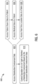
- Figure 6 shows an example of logic 600 that a system may implement to support control of UV lights to disinfect patient rooms.
- the building automation system 100 may implement the logic 600 as hardware, executable instructions stored on a machine-readable medium, or as a combination of both.
- the building automation system 100 may implement the logic 600 through the disinfection environment tracking engine 108 and the UV light control engine 110, through which the building automation system 100 may perform or execute the logic 600 as a method to control UV lights for room disinfection.
- the following description of the logic 600 is provided using the disinfection environment tracking engine 108 and the UV light control engine 110 as examples. However, various other implementation options by the building automation system 100 are possible.
- the disinfection environment tracking engine 108 may access disinfection environment data (602).
- the disinfection environment data may include any data relevant to a disinfection environment, whether it be a patient room or other space, as well as any other data that may impact UV light disinfection, such as medical data, occupancy time periods, and the like.
- the disinfection environment tracking engine 108 may access patient room data of a patient (604), access medical data of the patient (606), and access real-time location data of the patient (608).
- the UV light control engine 110 may control operation of a UV light to disinfect a disinfection environment based on the accessed in disinfection environment data (610).
- FIG. 7 shows an example of a system that supports control of UV lights to disinfect patient rooms or other disinfection environments.
- the system 700 may include a processor 710, which may take the form of a single or multiple processors.
- the processor(s) 710 may include a central processing unit (CPU), microprocessor, or any hardware device suitable for executing instructions stored on a machine-readable medium.
- the system 700 may include a machine-readable medium 720.
- the machine-readable medium 720 may take the form of any non-transitory electronic, magnetic, optical, or other physical storage device that stores executable instructions, such as the disinfection environment tracking instructions 722 and the UV light control instructions 724 shown in Figure 7 .
- the machine-readable medium 720 may be, for example, Random Access Memory (RAM) such as a dynamic RAM (DRAM), flash memory, spin-transfer torque memory, an Electrically-Erasable Programmable Read-Only Memory (EEPROM), a storage drive, an optical disk, and the like.
- RAM Random Access Memory
- DRAM dynamic RAM
- EEPROM Electrically-Erasable Programmable Read-Only Memory
- storage drive an optical disk, and the like.
- the system 700 may execute instructions stored on the machine-readable medium 720 through the processor 710. Executing the instructions may cause the system 700 (e.g., a building automation system) to perform any of the UV light control features described herein, including according to any of the features with respect to the building automation system 100, the disinfection environment tracking engine 108, the UV light control engine 110, or combinations thereof.
- execution of the disinfection environment tracking instructions 722 by the processor 710 may cause the system 700 to access patient room data indicative of a state of a patient room of a patient, the patient room data including an occupancy schedule for the patient room that indicates an unoccupied time period during which the patient does not occupy the room and access medical data of the patient, the medical data of the patient specifying a medical condition of the patient.
- Execution of the UV light control instructions 724 by the processor 710 may cause the system 700 to control operation of UV light to disinfect the patient room based on the patient room data and the medical condition of the data, including by calibrating the UV light to account for a length of the unoccupied time period and a severity of the medical condition of the patient.
- the systems, methods, devices, and logic described above, including the building automation system 100, the disinfection environment tracking engine 108, and the UV light control engine 110, may be implemented in many different ways in many different combinations of hardware, logic, circuitry, and executable instructions stored on a machine-readable medium.
- the building automation system 100, the disinfection environment tracking engine 108, the UV light control engine 110, or combinations thereof may include circuitry in a controller, a microprocessor, or an application specific integrated circuit (ASIC), or may be implemented with discrete logic or components, or a combination of other types of analog or digital circuitry, combined on a single integrated circuit or distributed among multiple integrated circuits.
- ASIC application specific integrated circuit
- a product such as a computer program product, may include a storage medium and machine readable instructions stored on the medium, which when executed in an endpoint, computer system, or other device, cause the device to perform operations according to any of the description above, including according to any features of the building automation system 100, the disinfection environment tracking engine 108, the UV light control engine 110, or combinations thereof.
- the processing capability of the systems, devices, and engines described herein, including the building automation system 100, the disinfection environment tracking engine 108, and the UV light control engine 110, may be distributed among multiple system components, such as among multiple processors and memories, optionally including multiple distributed processing systems or cloud/network elements.
- Parameters, databases, and other data structures may be separately stored and managed, may be incorporated into a single memory or database, may be logically and physically organized in many different ways, and may implemented in many ways, including data structures such as linked lists, hash tables, or implicit storage mechanisms.
- Programs may be parts (e.g., subroutines) of a single program, separate programs, distributed across several memories and processors, or implemented in many different ways, such as in a library (e.g., a shared library).
Landscapes
- Health & Medical Sciences (AREA)
- Epidemiology (AREA)
- Life Sciences & Earth Sciences (AREA)
- Animal Behavior & Ethology (AREA)
- General Health & Medical Sciences (AREA)
- Public Health (AREA)
- Veterinary Medicine (AREA)
- Apparatus For Disinfection Or Sterilisation (AREA)
Claims (15)
- System (100), umfassend:
eine Tracking-Engine für Desinfektionsumgebungen (108), die konfiguriert ist zum:Zugreifen auf Patientenraumdaten, die einen Zustand eines Patientenraums (210) eines Patienten anzeigen;Zugreifen auf medizinische Daten des Patienten, wobei die medizinischen Daten des Patienten eine medizinische Bedingung des Patienten spezifizieren; undZugreifen auf Echtzeit-Aufenthaltsdaten des Patienten; undeine Steuer-Engine für Ultraviolettlicht (UV-Licht-Steuer-Engine) (110), die konfiguriert ist zum Steuern eines UV-Lichts (220), um einen Patientenraum (210), basierend auf den Patientenraumdaten, den medizinischen Daten des Patienten und den Echtzeit-Aufenthaltsdaten des Patienten, zu desinfizieren,wobei die UV-Licht-Steuer-Engine (110) ferner konfiguriert ist zum Steuern des Betriebs des UV-Lichts (220) durch:ein Aktivieren des UV-Lichts (220) während des nicht belegten Zeitraums als Reaktion auf eine Ermittlung aus den Echtzeit-Aufenthaltsdaten, dass der Patient mehr als einen Schwellenwertabstand von dem Patientenraum (210) entfernt ist; undein Deaktivieren des UV-Lichts (220) während des nicht belegten Zeitraums als Reaktion auf eine Ermittlung aus den Echtzeit-Aufenthaltsdaten, dass der Patient weniger als einen Schwellenwertabstand von dem Patientenraum (210) entfernt ist. - System (100) nach Anspruch 1, wobei die Patientenraumdaten einen Belegungsplan für den Patientenraum (210) umfassen, der spezifisch für den Patienten ist; und
wobei die UV-Licht-Steuer-Engine (110) konfiguriert ist zum Steuern des Betriebs des UV-Lichts (220) durch:ein Ermitteln einer Desinfektionszeitdauer für den Patientenraum (210) basierend auf der Schwere der medizinischen Bedingung des Patienten und einer Dauer eines belegten Zeitraums in dem Belegungsplan, in dem der Patient den Patientenraum (210) belegt;ein Identifizieren eines nicht belegten Zeitraums in dem Belegungsplan, in dem der Patient den Patient den Patientenraum (210) nicht belegt; undein Aktivieren des UV-Lichts (220), um den Patientenraum (210) während des nicht belegten Zeitraums als Reaktion auf eine Ermittlung zu desinfizieren, dass eine Dauer des nicht belegten Zeitraums die ermittelte Desinfektionszeitdauer überschreitet. - System nach Anspruch 1, wobei die Tracking-Engine für Desinfektionsumgebungen (108) konfiguriert ist zum Zugreifen auf die Patientenraumdaten, indem ein Belegungszustand des Patientenraums (210) von einem Belegungssensor (211) in dem Patientenraum (210) erhalten wird; und
wobei die UV-Licht-Steuer-Engine (110) konfiguriert ist zum Steuern des UV-Lichts (220), indem das UV-Licht (220) deaktiviert wird, wenn der Belegungszustand anzeigt, dass der Patientenraum (210) durch den Patienten oder eine andere Person belegt ist. - System nach Anspruch 1, wobei die UV-Licht-Steuer-Engine (110) konfiguriert ist zum Steuern des UV-Lichts (220), basierend auf den Patientenraumdaten, den medizinischen Daten des Patienten und den Echtzeit-Aufenthaltsdaten des Patienten, durch:
ein Reduzieren einer UV-Lichtintensität des UV-Lichts (220), um einen Energieverbrauch während eines nicht belegten Zeitraums des Patientenraums (210) zu reduzieren, wie er aus den Patientenraumdaten oder den Echtzeit-Aufenthaltsdaten des Patienten ermittelt wurde, sodass das UV-Licht (220) nichtsdestotrotz, basierend auf der medizinischen Bedingung des Patienten, wirkungsvoll zum Desinfizieren des Patientenraums (210) während des nicht belegten Zeitraums ist. - System nach Anspruch 1, wobei die UV-Licht-Steuer-Engine (110) konfiguriert ist zum Steuern des UV-Lichts (220) durch:ein Ermitteln, in einem Patienteninformationsverwaltungssystem, eines zugewiesenen Belegungszeitraums, während dem der Patient dem Patientenraum (210) zugewiesen ist;ein Ermitteln, in einem Patienteninformationsverwaltungssystem, eines Patientenbehandlungsplans für den Patienten während des zugewiesenen Belegungszeitraums, der nicht belegte Zeiträume beinhaltet, während denen der Patient nicht in dem Patientenraum (210) anwesend ist; undein Bestätigen, über die Echtzeit-Aufenthaltsdaten des Patienten, dass der Patient während der nicht belegten Zeiträume nicht in dem Patientenraum (210) anwesend ist, und als Reaktion darauf, ein Aktivieren des UV-Lichts (220), um den Patientenraum (210) während der nicht belegten Zeiträume zu desinfizieren.
- System nach Anspruch 1, wobei die UV-Licht-Steuer-Engine (110) ferner konfiguriert ist zum Senden einer Verriegelungsanforderung an ein physisches Zugangssteuerungssystem (PAS-System), um eine Tür des Patientenraums 210) zu verriegeln, wenn das UV-Licht (220) aktiv ist, um den Patientenraum (210) zu desinfizieren.
- Verfahren, umfassend:
durch ein Gebäudeautomationssystem:Zugreifen auf Patientenraumdaten, die einen Zustand eines Patientenraums (210) eines Patienten anzeigen;Zugreifen auf medizinische Daten des Patienten, wobei die medizinischen Daten des Patienten eine medizinische Bedingung des Patienten spezifizieren; undZugreifen auf Echtzeit-Aufenthaltsdaten des Patienten;
undSteuern des Betriebs eines Ultraviolettlichts (UV-Lichts) (220) durch eine Steuer-Engine für Ultraviolettlicht (UV-Licht-Steuer-Engine) (110), um den Patientenraum (210), basierend auf den Patientenraumdaten, den medizinischen Daten des Patienten und den Echtzeit-Aufenthaltsdaten des Patienten, zu desinfizieren,wobei die UV-Licht-Steuer-Engine (110) ferner konfiguriert ist zum Steuern des Betriebs des UV-Lichts (220) durch:ein Aktivieren des UV-Lichts (220) während des nicht belegten Zeitraums als Reaktion auf eine Ermittlung aus den Echtzeit-Aufenthaltsdaten, dass der Patient mehr als einen Schwellenwertabstand von dem Patientenraum (210) entfernt ist; undein Deaktivieren des UV-Lichts (220) während des nicht belegten Zeitraums als Reaktion auf eine Ermittlung aus den Echtzeit-Aufenthaltsdaten, dass der Patient weniger als einen Schwellenwertabstand von dem Patientenraum (210) entfernt ist. - Verfahren nach Anspruch 7, wobei das Zugreifen auf die Patientenraumdaten ein Zugreifen auf einen Belegungszustand des Patientenraums (210) von einem Belegungssensor (211) in dem Patientenraum (210) umfasst; und
wobei das Steuern des UV-Lichts (220) umfasst:Aktivieren des UV-Lichts (220), um den Patientenraum (210) zu einem Zeitpunkt zu desinfizieren, wenn der Belegungszustand anzeigt, dass der Patientenraum (210) nicht belegt ist; undDeaktivieren des UV-Lichts (220), wenn der Belegungszustand anzeigt, dass der Patientenraum (210) belegt ist. - Verfahren nach Anspruch 7, wobei das Zugreifen auf die Patientenraumdaten ein Zugreifen auf einen Belegungsplan für den Patientenraum (210) umfasst, der spezifisch für den Patienten ist; und
wobei das Steuern des UV-Lichts (220) umfasst:Aktivieren des UV-Lichts (220) während eines nicht belegten Zeitraums, wobei der Belegungsplan anzeigt, dass der Patient den Patientenraum (210) nicht belegen wird; undKalibrieren einer Eigenschaft des UV-Lichts, um eine Desinfektionszeitdauer für den Patientenraum (210), basierend auf einer Dauer des nicht belegten Zeitraums, zu beeinflussen, der durch den Belegungsplan angezeigt wird, wobei das Kalibrieren der Eigenschaft des UV-Lichts insbesondere ein Reduzieren der UV-Lichtintensität oder einer Desinfektionszeitdauer umfasst, in der das UV-Licht (220) während des nicht belegten Zeitraums aktiv ist, um den Energieverbrauch zu reduzieren. - Verfahren nach Anspruch 7, das ferner ein Zugreifen auf Echtzeit-Aufenthaltsdaten des Patienten umfasst; und
Steuern des Betriebs des UV-Lichts (220), um den Patientenraum (210), basierend auf sowohl den Echtzeit-Aufenthaltsdaten des Patienten als auch den Patientenraumdaten, zu desinfizieren, wobei das Steuern des Betriebs des UV-Lichts (220), um den Patientenraum (210), basierend auf sowohl den Echtzeit-Aufenthaltsdaten des Patienten als auch den Patientenraumdaten, zu desinfizieren, insbesondere umfasst:
Deaktivieren des UV-Lichts (220), wenn die Echtzeit-Aufenthaltsdaten anzeigen, dass der Patient weniger als einen Schwellenwertabstand von dem Patientenraum (210) entfernt ist. - Verfahren nach Anspruch 7, das ferner ein Zugreifen auf medizinische Daten des Patienten umfasst, wobei die medizinischen Daten des Patienten eine medizinische Bedingung des Patienten spezifizieren; und
ein Steuern des Betriebs des UV-Lichts (220) umfasst, um den Patientenraum (210), basierend auf sowohl den medizinischen Daten des Patienten als auch den Patientenraumdaten, zu desinfizieren, was ein Kalibrieren einer Eigenschaft des UV-Lichts beinhaltet, um die medizinische Bedingung des Patienten zu berücksichtigen. - Verfahren nach Anspruch 7, das ferner ein Senden einer Verriegelungsanforderung an ein physisches Zugangssteuerungssystem (PAS-System) umfasst, um eine Tür des Patientenraums 210) zu verriegeln, wenn das UV-Licht (220) aktiv ist, um den Patientenraum (210) zu desinfizieren.
- Nicht-flüchtiges maschinenlesbares Medium, das ein Speichern von Anweisungen umfasst, die, wenn sie von einem Prozessor ausgeführt werden, ein System veranlassen zum:Zugreifen auf Patientenraumdaten, die einen Zustand eines Patientenraums (210) eines Patienten anzeigen, wobei die Patientenraumdaten einen Belegungsplan für den Patientenraum (210) beinhalten, der einen nicht belegten Zeitraum anzeigt, während dem der Patient den Raum nicht belegt;Zugreifen auf medizinische Daten des Patienten, wobei die medizinischen Daten des Patienten eine medizinische Bedingung des Patienten spezifizieren; undSteuern eines Betriebs eines Ultraviolettlichts (UV-Lichts) (200) durch eine UV-Licht-Steuer-Engine (110), um den Patientenraum (210), basierend auf den Patientenraumdaten, den medizinischen Daten des Patienten und den Echtzeit-Aufenthaltsdaten des Patienten, zu desinfizieren,wobei die UV-Licht-Steuer-Engine (110) ferner konfiguriert ist zum Steuern des Betriebs des UV-Lichts (220) durch:ein Aktivieren des UV-Lichts (220) während des nicht belegten Zeitraums als Reaktion auf eine Ermittlung aus den Echtzeit-Aufenthaltsdaten, dass der Patient mehr als einen Schwellenwertabstand von dem Patientenraum (210) entfernt ist; undein Deaktivieren des UV-Lichts (220) während des nicht belegten Zeitraums als Reaktion auf eine Ermittlung aus den Echtzeit-Aufenthaltsdaten, dass der Patient weniger als einen Schwellenwertabstand von dem Patientenraum (210) entfernt ist.
- Nicht-flüchtiges maschinenlesbares Medium nach Anspruch 13, das ferner Anweisungen umfasst, die das System veranlassen, auf Echtzeit-Aufenthaltsdaten des Patienten zuzugreifen; undwobei die Anweisungen das System veranlassen, den Betrieb des UV-Lichts (220), basierend auf den Patientenraumdaten, der medizinischen Bedingung des Patienten und den Echtzeit-Aufenthaltsdaten des Patienten, zu steuern,wobei die Anweisungen das System insbesondere veranlassen, den Betrieb des UV-Lichts (220) zu steuern durch:ein Ermitteln, aus den Echtzeit-Aufenthaltsdaten des Patienten, einen belegten Zeitraum, in dem der Patient den Patientenraum (210) belegt hat; undein Kalibrieren des UV-Lichts (220), um außerdem eine Dauer des belegten Zeitraums zu berücksichtigen.
- Nicht-flüchtiges maschinenlesbares Medium nach Anspruch 13, wobei die Anweisungen das System veranlassen, das UV-Licht (220) zu kalibrieren, indem eine UV-Lichtintensität oder eine UV-Desinfektionszeitdauer reduziert werden, in der das UV-Licht (220) während des nicht belegten Zeitraums aktiv ist, um einen Energieverbrauch zu reduzieren, oder
wobei das nicht-flüchtige maschinenlesbare Medium ferner Anweisungen umfasst, die das System veranlassen eine Verriegelungsanforderung an ein physisches Zugangssteuerungssystem (PAS-System) zu senden, um eine Tür des Patientenraums 210) zu verriegeln, wenn das UV-Licht (220) aktiv ist, um den Patientenraum (210) zu desinfizieren.
Applications Claiming Priority (2)
| Application Number | Priority Date | Filing Date | Title |
|---|---|---|---|
| US16/026,317 US11278637B2 (en) | 2018-07-03 | 2018-07-03 | Systems and methods for intelligent disinfection of disinfection environments through use of ultra-violet lights |
| PCT/US2019/040089 WO2020009975A1 (en) | 2018-07-03 | 2019-07-01 | Systems and methods for intelligent disinfection of disinfection environments through use of ultra-violet lights |
Publications (2)
| Publication Number | Publication Date |
|---|---|
| EP3801644A1 EP3801644A1 (de) | 2021-04-14 |
| EP3801644B1 true EP3801644B1 (de) | 2025-06-04 |
Family
ID=67441628
Family Applications (1)
| Application Number | Title | Priority Date | Filing Date |
|---|---|---|---|
| EP19745385.5A Active EP3801644B1 (de) | 2018-07-03 | 2019-07-01 | Systeme und verfahren zur intelligenten desinfektion von desinfektionsumgebungen mittels verwendung von ultraviolettem licht |
Country Status (5)
| Country | Link |
|---|---|
| US (1) | US11278637B2 (de) |
| EP (1) | EP3801644B1 (de) |
| CN (1) | CN112672767B (de) |
| CA (1) | CA3105511C (de) |
| WO (1) | WO2020009975A1 (de) |
Families Citing this family (47)
| Publication number | Priority date | Publication date | Assignee | Title |
|---|---|---|---|---|
| WO2018183710A1 (en) | 2017-03-31 | 2018-10-04 | Honeywell International Inc. | Providing a comfort dashboard |
| US11025563B2 (en) | 2017-04-13 | 2021-06-01 | Johnson Controls Technology Company | Space-aware network switch |
| US10073440B1 (en) * | 2018-02-13 | 2018-09-11 | University Of Central Florida Research Foundation, Inc. | Method for the design and manufacture of composites having tunable physical properties |
| CA3054216C (en) | 2018-09-05 | 2023-08-01 | Honeywell International Inc. | Methods and systems for improving infection control in a facility |
| US11269306B2 (en) | 2019-07-12 | 2022-03-08 | Johnson Controls Tyco IP Holdings LLP | HVAC system with building infection control |
| US11960261B2 (en) | 2019-07-12 | 2024-04-16 | Johnson Controls Tyco IP Holdings LLP | HVAC system with sustainability and emissions controls |
| US12007732B2 (en) | 2019-07-12 | 2024-06-11 | Johnson Controls Tyco IP Holdings LLP | HVAC system with building infection control |
| US10978199B2 (en) | 2019-01-11 | 2021-04-13 | Honeywell International Inc. | Methods and systems for improving infection control in a building |
| US12529490B2 (en) | 2019-07-12 | 2026-01-20 | Tyco Fire & Security Gmbh | Infection control tool for HVAC system |
| US12264828B2 (en) | 2019-07-12 | 2025-04-01 | Tyco Fire & Security Gmbh | Air quality control and disinfection system |
| US11511423B2 (en) * | 2020-03-31 | 2022-11-29 | Uvd Robots Aps | Method of plotting ultraviolet (UV) radiation for disinfection |
| CN111544641A (zh) * | 2020-04-22 | 2020-08-18 | 西安交通大学 | 一种基于物联网的室内紫外线杀菌、消毒调控系统 |
| JP2021179697A (ja) * | 2020-05-11 | 2021-11-18 | キヤノンメディカルシステムズ株式会社 | 医用画像診断装置及び消毒管理装置 |
| US11536476B2 (en) * | 2020-05-12 | 2022-12-27 | Johnson Controls Tyco IP Holdings LLP | Building system with flexible facility operation |
| TWI834876B (zh) * | 2020-05-14 | 2024-03-11 | 微星科技股份有限公司 | 場域消毒機器人及控制方法 |
| US11620594B2 (en) | 2020-06-12 | 2023-04-04 | Honeywell International Inc. | Space utilization patterns for building optimization |
| US11783658B2 (en) | 2020-06-15 | 2023-10-10 | Honeywell International Inc. | Methods and systems for maintaining a healthy building |
| US20210390474A1 (en) | 2020-06-15 | 2021-12-16 | Honeywell International Inc. | Dashboard for multi site management system |
| US11783652B2 (en) | 2020-06-15 | 2023-10-10 | Honeywell International Inc. | Occupant health monitoring for buildings |
| US11914336B2 (en) | 2020-06-15 | 2024-02-27 | Honeywell International Inc. | Platform agnostic systems and methods for building management systems |
| US11823295B2 (en) | 2020-06-19 | 2023-11-21 | Honeywell International, Inc. | Systems and methods for reducing risk of pathogen exposure within a space |
| US11184739B1 (en) | 2020-06-19 | 2021-11-23 | Honeywel International Inc. | Using smart occupancy detection and control in buildings to reduce disease transmission |
| US12142385B2 (en) | 2020-06-22 | 2024-11-12 | Honeywell International Inc. | Methods and systems for reducing a risk of spread of disease among people in a space |
| US12131828B2 (en) | 2020-06-22 | 2024-10-29 | Honeywell Internationa Inc. | Devices, systems, and methods for assessing facility compliance with infectious disease guidance |
| US11276024B2 (en) | 2020-06-25 | 2022-03-15 | Johnson Controls Tyco IP Holdings LLP | Systems and methods for managing a trusted service provider network |
| US11619414B2 (en) | 2020-07-07 | 2023-04-04 | Honeywell International Inc. | System to profile, measure, enable and monitor building air quality |
| US12524786B2 (en) | 2020-08-04 | 2026-01-13 | Honeywell International Inc. | Methods and systems for determining guest satisfaction including guest sleep quality in hotels |
| US11402113B2 (en) | 2020-08-04 | 2022-08-02 | Honeywell International Inc. | Methods and systems for evaluating energy conservation and guest satisfaction in hotels |
| US12311082B2 (en) * | 2020-08-14 | 2025-05-27 | Fujifilm Business Innovation Corp. | Information processing system, non-transitory computer readable medium, and booth |
| US11894145B2 (en) | 2020-09-30 | 2024-02-06 | Honeywell International Inc. | Dashboard for tracking healthy building performance |
| US20220118135A1 (en) * | 2020-10-16 | 2022-04-21 | Honeywell International Inc. | Air and surface disinfection systems and methods |
| US11372383B1 (en) | 2021-02-26 | 2022-06-28 | Honeywell International Inc. | Healthy building dashboard facilitated by hierarchical model of building control assets |
| US11662115B2 (en) | 2021-02-26 | 2023-05-30 | Honeywell International Inc. | Hierarchy model builder for building a hierarchical model of control assets |
| US12142382B2 (en) | 2021-03-01 | 2024-11-12 | Honeywell International Inc. | Airborne infection early warning system |
| US11474489B1 (en) | 2021-03-29 | 2022-10-18 | Honeywell International Inc. | Methods and systems for improving building performance |
| JP7665388B2 (ja) * | 2021-04-08 | 2025-04-21 | キヤノンメディカルシステムズ株式会社 | 医用画像診断装置及び制御方法 |
| US12398905B2 (en) | 2021-05-28 | 2025-08-26 | Tyco Fire & Security Gmbh | Building control system with multi-objective control of carbon emissions and occupant comfort |
| US12261434B2 (en) | 2022-02-10 | 2025-03-25 | Tyco Fire & Security Gmbh | Control system with multi-factor carbon emissions optimization |
| US12529492B2 (en) | 2021-05-28 | 2026-01-20 | Tyco Fire & Security Gmbh | Building control system with predictive control of carbon emissions using marginal operating emissions rate |
| US12453796B1 (en) * | 2021-07-15 | 2025-10-28 | United Services Automobile Association (Usaa) | Targeted building sanitation |
| WO2023042349A1 (ja) * | 2021-09-16 | 2023-03-23 | パナソニックIpマネジメント株式会社 | 客室除菌システム |
| US12038187B2 (en) | 2021-09-28 | 2024-07-16 | Honeywell International Inc. | Multi-sensor platform for a building |
| CN114042174B (zh) * | 2021-10-11 | 2023-04-07 | 广汽本田汽车有限公司 | 车内紫外线消杀系统的控制方法、装置及存储介质 |
| WO2023147167A2 (en) * | 2022-01-31 | 2023-08-03 | Uv Partners, Inc. | Low profile light delivery system |
| CN114767910A (zh) * | 2022-04-13 | 2022-07-22 | 山东浪潮新基建科技有限公司 | 一种消毒控制方法及控制器 |
| US12261448B2 (en) | 2022-06-07 | 2025-03-25 | Honeywell International Inc. | Low power sensor with energy harvesting |
| US12431621B2 (en) | 2023-01-26 | 2025-09-30 | Honeywell International Inc. | Compact dual band antenna |
Family Cites Families (10)
| Publication number | Priority date | Publication date | Assignee | Title |
|---|---|---|---|---|
| EP3868411A1 (de) * | 2009-12-08 | 2021-08-25 | Surfacide, LLC | Desinfektionssystem für harte oberflächen |
| BR112013026529A2 (pt) * | 2011-04-15 | 2016-09-20 | Samuel Richard Trapani | método e sistema de esterilização de ambiente |
| US20130085609A1 (en) * | 2011-09-30 | 2013-04-04 | Siemens Industry, Inc. | Occupancy driven patient room environmental control |
| AU2013296299B2 (en) * | 2012-08-01 | 2017-04-13 | The United States Of America As Represented By The Department Of Veterans Affairs | Methods for organizing the disinfection of one or more items contaminated with biological agents |
| WO2014152761A1 (en) * | 2013-03-14 | 2014-09-25 | Brian Mullen | Methods and systems for monitoring and treating individuals with sensory processing conditions |
| US9265678B2 (en) * | 2013-07-18 | 2016-02-23 | American Sterilizer Company | Modular patient care enclosure |
| WO2015168768A1 (en) | 2014-05-05 | 2015-11-12 | Sanuvox Technologies Inc. | Room decontamination system, method and controller |
| CA2989812C (en) * | 2015-06-26 | 2023-09-26 | Kenall Manufacturing Company | Method of providing doses of light sufficient to deactivate dangerous pathogens throughout a volumetric space over a period of time |
| US10153994B2 (en) | 2015-11-24 | 2018-12-11 | Teletracking Technologies, Inc. | Systems and methods for automated and centralized real-time event detection and communication |
| US20180017947A1 (en) | 2016-07-13 | 2018-01-18 | Siemens Industry, Inc. | System and method for optimizing building system control of patient rooms to enhance patient outcomes |
-
2018
- 2018-07-03 US US16/026,317 patent/US11278637B2/en active Active
-
2019
- 2019-07-01 WO PCT/US2019/040089 patent/WO2020009975A1/en not_active Ceased
- 2019-07-01 CA CA3105511A patent/CA3105511C/en active Active
- 2019-07-01 EP EP19745385.5A patent/EP3801644B1/de active Active
- 2019-07-01 CN CN201980057317.XA patent/CN112672767B/zh active Active
Also Published As
| Publication number | Publication date |
|---|---|
| CA3105511C (en) | 2023-02-21 |
| CN112672767A (zh) | 2021-04-16 |
| EP3801644A1 (de) | 2021-04-14 |
| US11278637B2 (en) | 2022-03-22 |
| US20200009280A1 (en) | 2020-01-09 |
| WO2020009975A1 (en) | 2020-01-09 |
| CN112672767B (zh) | 2022-09-13 |
| CA3105511A1 (en) | 2020-01-09 |
Similar Documents
| Publication | Publication Date | Title |
|---|---|---|
| CA3105511C (en) | Systems and methods for intelligent disinfection of disinfection environments through use of ultra-violet lights | |
| US11513486B2 (en) | Systems and methods for intelligent disinfection of susceptible environments based on occupant density | |
| US20240408254A1 (en) | Disinfection behavior tracking and ranking | |
| US20210052758A1 (en) | Room decontamination system, method and controller | |
| US10824825B2 (en) | Methods for organizing the disinfection of one or more items contaminated with biological agents | |
| US10010633B2 (en) | Room sterilization method and system | |
| AU2017256814B2 (en) | An autonomous disinfectant system | |
| US20200168339A1 (en) | Automated surface sterilization techniques | |
| KR101263488B1 (ko) | 축산 농장용 소독 장치 및 이의 제어 방법 | |
| WO2015026407A1 (en) | Room sterilization method and system | |
| WO2018132671A1 (en) | Fixed position hybrid germicidal irradiation apparatus, method, and system | |
| US20150379441A1 (en) | Shared asset management system | |
| US20130127615A1 (en) | Sanitization compliance monitoring system with security enhancements | |
| US20210027882A1 (en) | Methods and systems for improving infection control in a facility | |
| US20160042634A1 (en) | Method and system for monitoring and enforcing hand hygiene and sanitization | |
| EP3936158B1 (de) | Uv-strahler zum desinfizieren von räumen | |
| US20230121230A1 (en) | Method and system for motivating and monitoring hygiene compliance in a hospital or related environment |
Legal Events
| Date | Code | Title | Description |
|---|---|---|---|
| STAA | Information on the status of an ep patent application or granted ep patent |
Free format text: STATUS: UNKNOWN |
|
| STAA | Information on the status of an ep patent application or granted ep patent |
Free format text: STATUS: THE INTERNATIONAL PUBLICATION HAS BEEN MADE |
|
| PUAI | Public reference made under article 153(3) epc to a published international application that has entered the european phase |
Free format text: ORIGINAL CODE: 0009012 |
|
| STAA | Information on the status of an ep patent application or granted ep patent |
Free format text: STATUS: REQUEST FOR EXAMINATION WAS MADE |
|
| 17P | Request for examination filed |
Effective date: 20210105 |
|
| AK | Designated contracting states |
Kind code of ref document: A1 Designated state(s): AL AT BE BG CH CY CZ DE DK EE ES FI FR GB GR HR HU IE IS IT LI LT LU LV MC MK MT NL NO PL PT RO RS SE SI SK SM TR |
|
| AX | Request for extension of the european patent |
Extension state: BA ME |
|
| DAV | Request for validation of the european patent (deleted) | ||
| DAX | Request for extension of the european patent (deleted) | ||
| STAA | Information on the status of an ep patent application or granted ep patent |
Free format text: STATUS: EXAMINATION IS IN PROGRESS |
|
| 17Q | First examination report despatched |
Effective date: 20231215 |
|
| REG | Reference to a national code |
Ref country code: DE Ref legal event code: R079 Free format text: PREVIOUS MAIN CLASS: A61L0002100000 Ipc: A61L0002240000 Ref country code: DE Ref legal event code: R079 Ref document number: 602019070754 Country of ref document: DE Free format text: PREVIOUS MAIN CLASS: A61L0002100000 Ipc: A61L0002240000 |
|
| GRAP | Despatch of communication of intention to grant a patent |
Free format text: ORIGINAL CODE: EPIDOSNIGR1 |
|
| STAA | Information on the status of an ep patent application or granted ep patent |
Free format text: STATUS: GRANT OF PATENT IS INTENDED |
|
| RIC1 | Information provided on ipc code assigned before grant |
Ipc: A61L 9/20 20060101ALI20250120BHEP Ipc: A61L 2/10 20060101ALI20250120BHEP Ipc: A61L 2/24 20060101AFI20250120BHEP |
|
| INTG | Intention to grant announced |
Effective date: 20250205 |
|
| GRAS | Grant fee paid |
Free format text: ORIGINAL CODE: EPIDOSNIGR3 |
|
| GRAA | (expected) grant |
Free format text: ORIGINAL CODE: 0009210 |
|
| STAA | Information on the status of an ep patent application or granted ep patent |
Free format text: STATUS: THE PATENT HAS BEEN GRANTED |
|
| AK | Designated contracting states |
Kind code of ref document: B1 Designated state(s): AL AT BE BG CH CY CZ DE DK EE ES FI FR GB GR HR HU IE IS IT LI LT LU LV MC MK MT NL NO PL PT RO RS SE SI SK SM TR |
|
| REG | Reference to a national code |
Ref country code: GB Ref legal event code: FG4D |
|
| REG | Reference to a national code |
Ref country code: CH Ref legal event code: EP |
|
| REG | Reference to a national code |
Ref country code: DE Ref legal event code: R096 Ref document number: 602019070754 Country of ref document: DE |
|
| REG | Reference to a national code |
Ref country code: IE Ref legal event code: FG4D |
|
| REG | Reference to a national code |
Ref country code: CH Ref legal event code: U11 Free format text: ST27 STATUS EVENT CODE: U-0-0-U10-U11 (AS PROVIDED BY THE NATIONAL OFFICE) Effective date: 20251006 |
|
| REG | Reference to a national code |
Ref country code: NL Ref legal event code: MP Effective date: 20250604 |
|
| PG25 | Lapsed in a contracting state [announced via postgrant information from national office to epo] |
Ref country code: FI Free format text: LAPSE BECAUSE OF FAILURE TO SUBMIT A TRANSLATION OF THE DESCRIPTION OR TO PAY THE FEE WITHIN THE PRESCRIBED TIME-LIMIT Effective date: 20250604 Ref country code: ES Free format text: LAPSE BECAUSE OF FAILURE TO SUBMIT A TRANSLATION OF THE DESCRIPTION OR TO PAY THE FEE WITHIN THE PRESCRIBED TIME-LIMIT Effective date: 20250604 |
|
| PGFP | Annual fee paid to national office [announced via postgrant information from national office to epo] |
Ref country code: DE Payment date: 20250919 Year of fee payment: 7 |
|
| REG | Reference to a national code |
Ref country code: LT Ref legal event code: MG9D |
|
| PG25 | Lapsed in a contracting state [announced via postgrant information from national office to epo] |
Ref country code: GR Free format text: LAPSE BECAUSE OF FAILURE TO SUBMIT A TRANSLATION OF THE DESCRIPTION OR TO PAY THE FEE WITHIN THE PRESCRIBED TIME-LIMIT Effective date: 20250905 Ref country code: NO Free format text: LAPSE BECAUSE OF FAILURE TO SUBMIT A TRANSLATION OF THE DESCRIPTION OR TO PAY THE FEE WITHIN THE PRESCRIBED TIME-LIMIT Effective date: 20250904 |
|
| PG25 | Lapsed in a contracting state [announced via postgrant information from national office to epo] |
Ref country code: PL Free format text: LAPSE BECAUSE OF FAILURE TO SUBMIT A TRANSLATION OF THE DESCRIPTION OR TO PAY THE FEE WITHIN THE PRESCRIBED TIME-LIMIT Effective date: 20250604 |
|
| PG25 | Lapsed in a contracting state [announced via postgrant information from national office to epo] |
Ref country code: BG Free format text: LAPSE BECAUSE OF FAILURE TO SUBMIT A TRANSLATION OF THE DESCRIPTION OR TO PAY THE FEE WITHIN THE PRESCRIBED TIME-LIMIT Effective date: 20250604 |
|
| PGFP | Annual fee paid to national office [announced via postgrant information from national office to epo] |
Ref country code: GB Payment date: 20250811 Year of fee payment: 7 |
|
| PG25 | Lapsed in a contracting state [announced via postgrant information from national office to epo] |
Ref country code: HR Free format text: LAPSE BECAUSE OF FAILURE TO SUBMIT A TRANSLATION OF THE DESCRIPTION OR TO PAY THE FEE WITHIN THE PRESCRIBED TIME-LIMIT Effective date: 20250604 |
|
| PGFP | Annual fee paid to national office [announced via postgrant information from national office to epo] |
Ref country code: AT Payment date: 20250606 Year of fee payment: 7 Ref country code: FR Payment date: 20250716 Year of fee payment: 7 |
|
| PG25 | Lapsed in a contracting state [announced via postgrant information from national office to epo] |
Ref country code: RS Free format text: LAPSE BECAUSE OF FAILURE TO SUBMIT A TRANSLATION OF THE DESCRIPTION OR TO PAY THE FEE WITHIN THE PRESCRIBED TIME-LIMIT Effective date: 20250904 |
|
| PG25 | Lapsed in a contracting state [announced via postgrant information from national office to epo] |
Ref country code: LV Free format text: LAPSE BECAUSE OF FAILURE TO SUBMIT A TRANSLATION OF THE DESCRIPTION OR TO PAY THE FEE WITHIN THE PRESCRIBED TIME-LIMIT Effective date: 20250604 |
|
| PG25 | Lapsed in a contracting state [announced via postgrant information from national office to epo] |
Ref country code: NL Free format text: LAPSE BECAUSE OF FAILURE TO SUBMIT A TRANSLATION OF THE DESCRIPTION OR TO PAY THE FEE WITHIN THE PRESCRIBED TIME-LIMIT Effective date: 20250604 |
|
| PG25 | Lapsed in a contracting state [announced via postgrant information from national office to epo] |
Ref country code: PT Free format text: LAPSE BECAUSE OF FAILURE TO SUBMIT A TRANSLATION OF THE DESCRIPTION OR TO PAY THE FEE WITHIN THE PRESCRIBED TIME-LIMIT Effective date: 20251006 |
|
| PG25 | Lapsed in a contracting state [announced via postgrant information from national office to epo] |
Ref country code: IS Free format text: LAPSE BECAUSE OF FAILURE TO SUBMIT A TRANSLATION OF THE DESCRIPTION OR TO PAY THE FEE WITHIN THE PRESCRIBED TIME-LIMIT Effective date: 20251004 |
|
| PG25 | Lapsed in a contracting state [announced via postgrant information from national office to epo] |
Ref country code: SM Free format text: LAPSE BECAUSE OF FAILURE TO SUBMIT A TRANSLATION OF THE DESCRIPTION OR TO PAY THE FEE WITHIN THE PRESCRIBED TIME-LIMIT Effective date: 20250604 |
|
| PGFP | Annual fee paid to national office [announced via postgrant information from national office to epo] |
Ref country code: CH Payment date: 20251006 Year of fee payment: 7 |
|
| PG25 | Lapsed in a contracting state [announced via postgrant information from national office to epo] |
Ref country code: CZ Free format text: LAPSE BECAUSE OF FAILURE TO SUBMIT A TRANSLATION OF THE DESCRIPTION OR TO PAY THE FEE WITHIN THE PRESCRIBED TIME-LIMIT Effective date: 20250604 |
|
| PG25 | Lapsed in a contracting state [announced via postgrant information from national office to epo] |
Ref country code: EE Free format text: LAPSE BECAUSE OF FAILURE TO SUBMIT A TRANSLATION OF THE DESCRIPTION OR TO PAY THE FEE WITHIN THE PRESCRIBED TIME-LIMIT Effective date: 20250604 |
|
| PG25 | Lapsed in a contracting state [announced via postgrant information from national office to epo] |
Ref country code: SK Free format text: LAPSE BECAUSE OF FAILURE TO SUBMIT A TRANSLATION OF THE DESCRIPTION OR TO PAY THE FEE WITHIN THE PRESCRIBED TIME-LIMIT Effective date: 20250604 Ref country code: RO Free format text: LAPSE BECAUSE OF FAILURE TO SUBMIT A TRANSLATION OF THE DESCRIPTION OR TO PAY THE FEE WITHIN THE PRESCRIBED TIME-LIMIT Effective date: 20250604 |
|
| PG25 | Lapsed in a contracting state [announced via postgrant information from national office to epo] |
Ref country code: IT Free format text: LAPSE BECAUSE OF FAILURE TO SUBMIT A TRANSLATION OF THE DESCRIPTION OR TO PAY THE FEE WITHIN THE PRESCRIBED TIME-LIMIT Effective date: 20250604 |
|
| REG | Reference to a national code |
Ref country code: DE Ref legal event code: R097 Ref document number: 602019070754 Country of ref document: DE |
|
| PG25 | Lapsed in a contracting state [announced via postgrant information from national office to epo] |
Ref country code: LU Free format text: LAPSE BECAUSE OF NON-PAYMENT OF DUE FEES Effective date: 20250701 |
|
| REG | Reference to a national code |
Ref country code: BE Ref legal event code: MM Effective date: 20250731 |
|
| PG25 | Lapsed in a contracting state [announced via postgrant information from national office to epo] |
Ref country code: MC Free format text: LAPSE BECAUSE OF FAILURE TO SUBMIT A TRANSLATION OF THE DESCRIPTION OR TO PAY THE FEE WITHIN THE PRESCRIBED TIME-LIMIT Effective date: 20250604 |
|
| PLBE | No opposition filed within time limit |
Free format text: ORIGINAL CODE: 0009261 |
|
| STAA | Information on the status of an ep patent application or granted ep patent |
Free format text: STATUS: NO OPPOSITION FILED WITHIN TIME LIMIT |
|
| PG25 | Lapsed in a contracting state [announced via postgrant information from national office to epo] |
Ref country code: DK Free format text: LAPSE BECAUSE OF FAILURE TO SUBMIT A TRANSLATION OF THE DESCRIPTION OR TO PAY THE FEE WITHIN THE PRESCRIBED TIME-LIMIT Effective date: 20250604 |
|
| PG25 | Lapsed in a contracting state [announced via postgrant information from national office to epo] |
Ref country code: BE Free format text: LAPSE BECAUSE OF NON-PAYMENT OF DUE FEES Effective date: 20250731 |
|
| REG | Reference to a national code |
Ref country code: CH Ref legal event code: L10 Free format text: ST27 STATUS EVENT CODE: U-0-0-L10-L00 (AS PROVIDED BY THE NATIONAL OFFICE) Effective date: 20260416 |
|
| 26N | No opposition filed |
Effective date: 20260305 |