EP3801433B1 - Armstützvorrichtung - Google Patents
Armstützvorrichtung Download PDFInfo
- Publication number
- EP3801433B1 EP3801433B1 EP19811154.4A EP19811154A EP3801433B1 EP 3801433 B1 EP3801433 B1 EP 3801433B1 EP 19811154 A EP19811154 A EP 19811154A EP 3801433 B1 EP3801433 B1 EP 3801433B1
- Authority
- EP
- European Patent Office
- Prior art keywords
- arm
- base
- barrier
- arm pad
- human patient
- Prior art date
- Legal status (The legal status is an assumption and is not a legal conclusion. Google has not performed a legal analysis and makes no representation as to the accuracy of the status listed.)
- Active
Links
Images







Classifications
-
- A—HUMAN NECESSITIES
- A61—MEDICAL OR VETERINARY SCIENCE; HYGIENE
- A61B—DIAGNOSIS; SURGERY; IDENTIFICATION
- A61B6/00—Apparatus or devices for radiation diagnosis; Apparatus or devices for radiation diagnosis combined with radiation therapy equipment
- A61B6/04—Positioning of patients; Tiltable beds or the like
-
- A—HUMAN NECESSITIES
- A61—MEDICAL OR VETERINARY SCIENCE; HYGIENE
- A61B—DIAGNOSIS; SURGERY; IDENTIFICATION
- A61B6/00—Apparatus or devices for radiation diagnosis; Apparatus or devices for radiation diagnosis combined with radiation therapy equipment
- A61B6/10—Safety means specially adapted therefor
- A61B6/107—Protection against radiation, e.g. shielding
-
- A—HUMAN NECESSITIES
- A61—MEDICAL OR VETERINARY SCIENCE; HYGIENE
- A61G—TRANSPORT, PERSONAL CONVEYANCES, OR ACCOMMODATION SPECIALLY ADAPTED FOR PATIENTS OR DISABLED PERSONS; OPERATING TABLES OR CHAIRS; CHAIRS FOR DENTISTRY; FUNERAL DEVICES
- A61G13/00—Operating tables; Auxiliary appliances therefor
- A61G13/10—Parts, details or accessories
- A61G13/12—Rests specially adapted therefor; Arrangements of patient-supporting surfaces
- A61G13/1205—Rests specially adapted therefor; Arrangements of patient-supporting surfaces for specific parts of the body
- A61G13/1235—Arms
-
- A—HUMAN NECESSITIES
- A61—MEDICAL OR VETERINARY SCIENCE; HYGIENE
- A61B—DIAGNOSIS; SURGERY; IDENTIFICATION
- A61B6/00—Apparatus or devices for radiation diagnosis; Apparatus or devices for radiation diagnosis combined with radiation therapy equipment
- A61B6/04—Positioning of patients; Tiltable beds or the like
- A61B6/0407—Supports, e.g. tables or beds, for the body or parts of the body
-
- A—HUMAN NECESSITIES
- A61—MEDICAL OR VETERINARY SCIENCE; HYGIENE
- A61G—TRANSPORT, PERSONAL CONVEYANCES, OR ACCOMMODATION SPECIALLY ADAPTED FOR PATIENTS OR DISABLED PERSONS; OPERATING TABLES OR CHAIRS; CHAIRS FOR DENTISTRY; FUNERAL DEVICES
- A61G13/00—Operating tables; Auxiliary appliances therefor
- A61G13/0036—Orthopaedic operating tables
- A61G13/0045—Orthopaedic operating tables specially adapted for hand or wrist surgeries
-
- A—HUMAN NECESSITIES
- A61—MEDICAL OR VETERINARY SCIENCE; HYGIENE
- A61G—TRANSPORT, PERSONAL CONVEYANCES, OR ACCOMMODATION SPECIALLY ADAPTED FOR PATIENTS OR DISABLED PERSONS; OPERATING TABLES OR CHAIRS; CHAIRS FOR DENTISTRY; FUNERAL DEVICES
- A61G13/00—Operating tables; Auxiliary appliances therefor
- A61G13/10—Parts, details or accessories
- A61G13/12—Rests specially adapted therefor; Arrangements of patient-supporting surfaces
- A61G13/1205—Rests specially adapted therefor; Arrangements of patient-supporting surfaces for specific parts of the body
-
- A—HUMAN NECESSITIES
- A61—MEDICAL OR VETERINARY SCIENCE; HYGIENE
- A61G—TRANSPORT, PERSONAL CONVEYANCES, OR ACCOMMODATION SPECIALLY ADAPTED FOR PATIENTS OR DISABLED PERSONS; OPERATING TABLES OR CHAIRS; CHAIRS FOR DENTISTRY; FUNERAL DEVICES
- A61G13/00—Operating tables; Auxiliary appliances therefor
- A61G13/10—Parts, details or accessories
- A61G13/12—Rests specially adapted therefor; Arrangements of patient-supporting surfaces
- A61G13/1205—Rests specially adapted therefor; Arrangements of patient-supporting surfaces for specific parts of the body
- A61G13/124—Hands or wrists
-
- A—HUMAN NECESSITIES
- A61—MEDICAL OR VETERINARY SCIENCE; HYGIENE
- A61G—TRANSPORT, PERSONAL CONVEYANCES, OR ACCOMMODATION SPECIALLY ADAPTED FOR PATIENTS OR DISABLED PERSONS; OPERATING TABLES OR CHAIRS; CHAIRS FOR DENTISTRY; FUNERAL DEVICES
- A61G2210/00—Devices for specific treatment or diagnosis
- A61G2210/50—Devices for specific treatment or diagnosis for radiography
Definitions
- the present disclosure relates generally to apparatuses for and methods of supporting a human patient's arm during medical procedures, and more particularly to gaining access to a human patient's radial artery during cardiac catheterization procedures.
- United States Publication No. 2016/038365 describes systems and methods for left radial access, right room operation peripheral interventions that include left radial bases to stabilize a left arm of a cardiac patient across a midsagittal plane, transradiant right radial bases to position a right arm of the patient, and radiodense radiation reduction barriers located between the patient and a doctor.
- United States Patent No. 9,763,843 describes a medical apparatus for use in supporting a patient lying in a supine position during a radial cardiac catheterization procedure. More particularly, an arm board is described for use with a patient's arm during a radial cardiac catheterization procedure.
- the arm board has a base member having a substantially planar support surface on which the patient's arm can be stabilized during a catheterization procedure and at least one shield member affixed to the base member and extending away from the support surface.
- the base member has both a radiolucent portion and a radiopaque portion and the shield member is a radiopaque material, thereby reducing and/or eliminating a doctor's exposure to radiation during radial cardiac catheterization procedures without impairing the ability to obtain the necessary medical images.
- an apparatus for supporting an arm of a human patient during a medical procedure as defined in the appended claim 1. Further optional features are recited in the associated dependent claims.
- an apparatus that can include: a base; a first barrier mounted to the base for shielding scatter radiation, the first barrier extending upwardly from the base; a second barrier mounted to the base for shielding scatter radiation, the second barrier extending downwardly from the base; and an arm pad on the base positioned laterally intermediate the first and second barriers, the arm pad including a proximal portion for supporting an arm of a human patient, and a central portion for supporting a hand of the arm.
- the method can include: positioning a base to lie between the human patient and a table on which the human patient is supported, the base including a lateral portion that extends laterally from the table; placing the arm of the human patient on an arm pad that is positioned on the lateral portion of the base; shielding scatter radiation with a first barrier, the first barrier mounted to the base and positioned laterally intermediate the lateral portion and the human patient, the first barrier extending upwardly from the base to above the arm pad; and shielding scatter radiation with a second barrier, the second barrier mounted to the lateral portion of the base and extending downwardly therefrom.
- arm support devices While more specific arm support devices have been created, they have many limitations, which can include: they can offer only modest, incremental radiation protection for the operating physician; they can increase patient and operator radiation dose and degrade the image quality due to the relative radiopacity and thickness of the materials used; and they can be inconvenient as they can require being removed between cases, or once the procedure begins, to avoid contaminating the sterile field.
- the present disclosure relates to arm support apparatuses that are well suited for use in gaining access to a human patient's radial arteries during cardiac catheterization procedures.
- FIG. 1 an example of an apparatus for supporting an arm of a human patient during a medical procedure is shown generally at reference number 10.
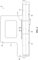
- the apparatus 10 as illustrated includes a base 12, and arm pad 14, a first barrier 16 and a second barrier 18.
- the arm pad supports the right arm of the human patient, and the first and second barriers 16, 18 can shield an attending staff member from scatter radiation during the medical procedure.
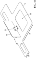
- the base 12 includes a medial portion 26 and a lateral portion 28.
- the medial portion 26 is configured to lie between the human patient and a table on which the human patient is supported.
- the lateral portion 28 extends in a lateral direction 22 from the medial portion 26.
- Figure 1 includes a directional legend, in which a longitudinal direction 20, the lateral direction 22, and a vertical direction 24 are shown.
- the arm pad 14 is positioned on the lateral portion 28 of the base 12.
- the arm pad 14 extends in the longitudinal direction 20 between first and second ends 30, 32.
- the arm pad 14 rests on the lateral portion 28, without being attached. This can allow adjustment of the position of the arm pad 14 according to patient's arm length. Therefore, the apparatus 10 can be customized to the patient's size without needing to move the patient or the base 12 underneath them.
- the arm pad 14 can be fixed to the lateral portion 28.
- the first barrier 16 is mounted to the base 12 and is positioned intermediate the medial and lateral portions 26, 28 in the lateral direction 22.
- the second barrier 18 is mounted to the lateral portion 28.
- the first barrier 16 extends upwardly from the base 12 in the vertical direction 24 to above the arm pad 14.
- the second barrier 18 extends downwardly from the base 12 in the vertical direction 24.
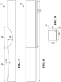
- the arm pad 14 includes a proximal portion 34 adjacent to the first end 30, a distal portion 36 adjacent to the second end 32, and a central portion 38 arranged between the proximal and distal portions 34, 36.
- the proximal portion 34 supports the arm of the human patient
- the central portion 38 supports a hand of the arm.
- the portions 34, 36, 38 each include an upper surface 40, 42, 44, respectively.
- each of the upper surfaces 40, 42, 44 is spaced above the lateral portion 28 of the base 12 in the vertical direction 24.
- the lateral portion 28 of the base 12 extends in the longitudinal direction 20 to support a length of the arm pad 14.
- the first and second barriers 16, 18 are each shown arranged longitudinally intermediate of the arm pad 14.
- the central portion 38 of the arm pad 14 is shown arranged within a longitudinal extent of each of the first and second barriers 16, 18. With this arrangement, in use, the first and second barriers 16, 18 provide shielding of radiation in the vicinity of the hand of the human patient.
- the arm pad 14 further includes a radiopaque panel 46.
- the panel 46 is arranged in the central and distal portions 38, 36 of the arm pad 14, horizontally and adjacent to the lateral portion 28 of the base 12.
- the panel 46 can extend generally laterally between the first and second barriers 16, 18 to provide shielding of radiation in the vicinity of the hand of the human patient.
- the lateral portion 28 of the base 12 extends laterally to support a width of the arm pad 14.
- the first barrier 16 is mounted to the base 12 and is positioned intermediate the medial and lateral portions 26, 28 in the lateral direction 22.
- the second barrier 18 is mounted to a lateral edge 94 of the lateral portion 28, and the arm pad 14 is positioned laterally intermediate the first and second barriers 16, 18.
- the upper surface 44 of the central portion 38 is substantially below the upper surface 40 of the proximal portion 34.
- the upper surface 44 of the central portion 38 is concave in shape to position the hand generally below the arm.
- the upper surface 42 of the distal portion 36 is shown to be generally planar and horizontal, and can be used by the attending staff as a working surface.
- the arm pad 14 can be formed of a foam material that is clad with marine grade vinyl.
- the radiopaque panel 46 can be formed of a relatively thin layer of lead, which can be disposed in the arm pad 14 underneath a bottom outer vinyl layer.
- the upper surface 42 of the distal portion 36 can be reinforced to create a stable working surface.
- the base 12 is shown to be generally planar and arranged horizontally.
- the base 12 can be formed at least partially of a substantially radiolucent material.
- the base 12 can be formed of a unitary piece of clear polycarbonate material.
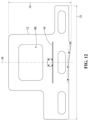
- the medial portion 26 of the base 12 includes a central aperture 66 that is positioned so that, in use, it is underneath an abdomen of the human patient.
- the lateral portion 28 is also shown to include a series of apertures 68.
- the apertures 66, 68 can be cutouts of the base 12 that reduce weight and decrease impedance during medical imaging.
- the first barrier 16 can be mounted to the base 12 by a flexible and resilient connection 70 to permit adjustment of its position.
- the connection 70 can be a curved bracket formed of spring steel, and fastened between the first barrier 16 and the base 12.
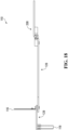
- each of the aperture 66, the first barrier 16 and the second barrier 18 can be aligned with a transverse axis 76.
- first and second barriers 16, 18 are each shown to be generally planar and arranged vertically.
- the first and second barriers 16, 18 can each be formed at least partially of a substantially radiopaque material.
- the first and second barriers 16, 18 can be formed of vinyl coated lead sheets.
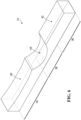
- the second barrier 18 includes first and second planar portions 78, 80.
- the planar portions 78, 80 have outward vertical edges 82, 84.
- the second planar portion 80 is joined to the first planar portion 78 at an oblique angle, so that the vertical edge 84 is spaced apart laterally from the vertical edge 82 in a direction away from the rest of the apparatus 10, which provides some clearance for a patient table.
- the apparatus 10 is shown supporting an arm 86 of a human patient 88.
- the human patient 88 is shown lying on a mattress 90 and a table 92.
- the medial portion of the base lies between the human patient 88 and the table 92. It will be appreciated that, in other examples, the medial portion of the base can be omitted, and an alternative means of attaching the apparatus to the side of the table can be used.
- the radiation barriers and panel can be substantially radiopaque, and can block significantly more radiation than existing shielding equipment.
- the apparatus can also be compatible with femoral access procedures, and provide radiation protection for such cases.
- the polycarbonate base can be more radiolucent than existing devices, which can reduce the amount of radiation needed during medical imaging. Furthermore, the position of the base under the patient's abdomen is also outside of the typical field of view (the patient's chest), which can prevent both increases in radiation and image degradation. Moreover, the positioning of the radiation barriers and panel can allow clear fluoroscopic visualization of the patient's arm.
- the working surface of the distal portion of the arm pad can be level with the patient's wrist and provide a convenient platform upon which the attending staff can manipulate equipment.
- the contoured shapes of the upper surfaces of the proximal and central portions of the arm pad can position the patient's wrist at a desirable angle, improving the attending staff's access to the patient's artery.
- the apparatus can be compatible with both radial and femoral access cases, the apparatus does not need to be removed between cases depending on the access site chosen.
- the arm pad can be relatively large and include contoured foam padding to provide full arm support and enhance patient comfort.
- the flexibility of the first barrier allows for multiple positions to accommodate the patient, and because it is not rigidly attached it can deflect if it is knocked by the patient or the attending staff.
- FIG. 110 another example of an apparatus for supporting an arm of a human patient during a medical procedure is shown generally at reference number 110.
- the apparatus 110 is shown to include a first barrier 116 and a second barrier 118.
- the primary arm pad (omitted for clarity of illustration) supports the right arm of the human patient, and the first and second barriers 116, 118 can shield an attending staff member from scatter radiation during the medical procedure.
- the apparatus 110 includes a base that includes a medial portion 126 and a lateral portion 128.
- the medial portion 126 is configured to lie between the human patient and a table on which the human patient is supported.
- the lateral portion 128 extends in a lateral direction 122 from the medial portion 126.
- a longitudinal direction 120, the lateral direction 122, and a vertical direction 124 are shown in Figure 16 .
- first and second barriers 116, 118 are each mounted to the lateral portion 128 and are spaced from one another in the lateral direction 122.
- the first barrier 116 extends upwardly in the vertical direction 124
- the second barrier 118 extends downwardly in the vertical direction 124.
- the apparatus 110 includes an additional support surface that is shown generally at reference numeral 200, which can be referred to as the "left wing".
- the left wing 200 is shown coupled to the medial portion 126 opposite from the lateral portion 128, and extends in the lateral direction 122 away from the medial portion 126. In use, the left wing 200 can support the left arm of the human patient.
- the lateral portion 128 extends laterally to support a width of the primary arm pad (not shown).
- the first barrier 116 is mounted adjacent to a first lateral edge of the lateral portion 128, and the second barrier 118 is mounted to a second lateral edge of the lateral portion 128.
- the medial and lateral portions 126, 128 of the base are separate components that are capable of disassembly.
- the medial portion 126 is arranged laterally intermediate the lateral portion 128 and the left wing 200.
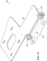
- the left wing 200 is shown to include an adjustable support 202 that is coupled to a mounting bracket 204 by hinge mechanisms 206, 208.
- the support 202 is shown to be generally planar and includes a plurality of cutouts.
- the support 202 includes a central cutout, intended to reduce weight, and four peripheral cutouts, which are designed to accept straps to secure a secondary arm pad (not shown) to the support 202.
- the support 202 has a relatively large upper portion, and a relatively narrow lower portion adjacent to the hinge mechanisms 206, 208, and is therefore shaped to be less intrusive when pivoted upwardly towards the patient.
- the support 202 can be pivoted about a longitudinal axis 210 by actuating a tab 212.
- the tab 212 disengages locks in the hinge mechanisms 206, 208 to permit pivoting of the support 202 about the axis 210. Releasing the tab 212 reengages the locks to fix the support 202 at a desired angle.
- the tab 212 is provided at the hinge mechanism 208, and coordination between the hinge mechanisms 206, 208 can be achieved via a shaft 214. This can allow for one handed adjustment of the left wing 200.
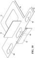
- Figure 21 shows disassembly of the lateral portion 128 and the left wing 200 from the medial portion 126.
- the lateral portion 128 and the left wing 200 each includes pins that are arranged to engage keyhole slots in the medial portion 126, permitting quick and easy assembly/disassembly.
- the primary arm pad 14 can rest on the lateral portion 128, and the secondary arm pad 216 is fixed to the left wing 200 by straps.
- Two straps are also shown attached to the medial portion 126, for securing the medial portion 126 to a mattress (not shown)
- the apparatus 110 is shown supporting arms 186, 196 of a human patient 188 lying on a mattress 190 and a table 192.
- Figure 22 shows the arm pad 216 and the left wing 200 in a generally horizontal position.
- the arm pad 216 can support the left arm 196 of the human patient 188 during a medical procedure, in which the left radial artery of the human patient 188 can be accessed, for example.
- the attending staff member can remain along the right hand side relative to the human patient 188, and the apparatus 110 can therefore continue to shield the attending staff member from scatter radiation.
- Figure 23 shows the left wing 200 in an upright position in which there is an acute angle between the support 202 and the medial portion 126. This can be a more comfortable position for the human patient 188 to maintain, after the left radial artery has been accessed, and during which images can be taken using a C-arm camera, for example.
- orientation including 'up', 'down', 'above', 'below', 'lateral', 'longitudinal', 'vertical' and 'horizontal', correspond to the arm board apparatus in use and are intended to aid with understanding, but need not refer to the orientation of various components during manufacture or when not in use.
Landscapes
- Health & Medical Sciences (AREA)
- Life Sciences & Earth Sciences (AREA)
- Engineering & Computer Science (AREA)
- Medical Informatics (AREA)
- Biomedical Technology (AREA)
- Animal Behavior & Ethology (AREA)
- General Health & Medical Sciences (AREA)
- Public Health (AREA)
- Veterinary Medicine (AREA)
- High Energy & Nuclear Physics (AREA)
- Biophysics (AREA)
- Physics & Mathematics (AREA)
- Nuclear Medicine, Radiotherapy & Molecular Imaging (AREA)
- Optics & Photonics (AREA)
- Pathology (AREA)
- Radiology & Medical Imaging (AREA)
- Heart & Thoracic Surgery (AREA)
- Molecular Biology (AREA)
- Surgery (AREA)
- Apparatus For Radiation Diagnosis (AREA)
Claims (15)
- Vorrichtung (10) zum Stützen eines Arms eines menschlichen Patienten während einer medizinischen Prozedur, wobei die Vorrichtung (10) Folgendes umfasst:eine Basis (12), umfassend einen medialen Abschnitt (26), der dazu konfiguriert ist, zwischen dem menschlichen Patienten und einem Tisch zu liegen, auf dem der menschliche Patient gestützt ist, und einen lateralen Abschnitt (28), der sich lateral von dem medialen Abschnitt (26) erstreckt;eine Armauflage (14), die an dem lateralen Abschnitt (28) der Basis (12) positioniert ist, wobei sich die Armauflage (14) längs zwischen dem ersten und dem zweiten Ende (30, 32) erstreckt;eine erste Barriere (16) zum Abschirmen von Streustrahlung während der medizinischen Prozedur, wobei die erste Barriere (16) an der Basis (12) montiert und lateral zwischen dem medialen und dem lateralen Abschnitt (26, 28) davon positioniert ist, wobei sich die erste Barriere (16) von der Basis (12) nach oben bis über die Armauflage (14) erstreckt; undeine zweite Barriere (18) zum Abschirmen von Streustrahlung während der medizinischen Prozedur, wobei die zweite Barriere (18) an dem lateralen Abschnitt (28) der Basis (12) montiert ist und sich von diesem nach unten erstreckt,wobei die Armauflage (14) eine strahlenundurchlässige Platte (46) umfasst.
- Vorrichtung (10) nach Anspruch 1, wobei die Armauflage (14) einen proximalen Abschnitt (34) benachbart zu dem ersten Ende (30) zum Stützen des Arms des menschlichen Patienten, einen distalen Abschnitt (36) benachbart zu dem zweiten Ende (32) und einen zentralen Abschnitt (38), der zwischen dem proximalen und dem distalen Abschnitt (34, 36) angeordnet ist, zum Stützen einer Hand des Arms umfasst.
- Vorrichtung (10) nach Anspruch 2, wobei eine obere Oberfläche (40) des proximalen Abschnitts (34) über dem lateralen Abschnitt (28) der Basis (12) beabstandet ist, eine obere Oberfläche (44) des zentralen Abschnitts (38) über dem lateralen Abschnitt (28) der Basis (12) beabstandet ist und die obere Oberfläche (44) des zentralen Abschnitts (38) im Wesentlichen unter der oberen Oberfläche (34) des proximalen Abschnitts (34) liegt und bevorzugt die obere Oberfläche (44) des zentralen Abschnitts (38) über eine konkave Form verfügt, um die Hand im Allgemeinen unter dem Arm zu positionieren.
- Vorrichtung (10) nach Anspruch 2 oder 3, wobei die erste Barriere (16) längs zwischen der Armauflage (14) angeordnet ist und die zweite Barriere (18) längs zwischen der Armauflage (14) angeordnet ist, sodass der zentrale Abschnitt (38) der Armauflage (14) innerhalb einer Längserstreckung jeder der ersten und der zweiten Barriere (16, 18) angeordnet ist.
- Vorrichtung (10) nach einem der Ansprüche 2 bis 4, wobei der distale Abschnitt (36) eine obere Oberfläche (42) umfasst, die im Allgemeinen eben und horizontal ist.
- Vorrichtung (10) nach einem der Ansprüche 2 bis 5, wobei die strahlenundurchlässige Platte (46) in dem zentralen und dem distalen Abschnitt (38, 36) der Armauflage (14) angeordnet ist und bevorzugt die strahlenundurchlässige Platte (46) horizontal und benachbart zu der Basis (12) angeordnet ist.
- Vorrichtung (10) nach einem der Ansprüche 1 bis 6, wobei die Basis (12) im Allgemeinen eben und mindestens teilweise aus einem im Wesentlichen strahlendurchlässigen Material gebildet ist und bevorzugt der mediale Abschnitt (26) der Basis (12) eine zentrale Öffnung (66) umfasst, die dazu konfiguriert ist, unterhalb eines Abdomens des menschlichen Patienten positioniert zu werden.
- Vorrichtung (10) nach einem der Ansprüche 1 bis 7, wobei sich der laterale Abschnitt (28) der Basis (12) längs erstreckt, um eine Länge der Armauflage (14) zu stützen, sich der laterale Abschnitt (28) der Basis (12) lateral erstreckt, um eine Breite der Armauflage (14) zu stützen, und bevorzugt die Armauflage (14) auf dem lateralen Abschnitt (28) ruht, ohne angebracht zu sein.
- Vorrichtung (10) nach einem der Ansprüche 1 bis 8, wobei die erste und die zweite Barriere (16, 18) jeweils im Allgemeinen eben und mindestens teilweise aus einem im Wesentlichen strahlenundurchlässigen Material gebildet sind und die erste und die zweite Barriere (16, 18) jeweils im Allgemeinen vertikal angeordnet sind.
- Vorrichtung (10) nach einem der Ansprüche 1 bis 9, wobei die erste Barriere (16) durch eine flexible und nachgiebige Verbindung (70) an der Basis (12) montiert ist.
- Vorrichtung (10) nach einem der Ansprüche 1 bis 10, wobei die zweite Barriere (18) an einer lateralen Kante (94) des lateralen Abschnitts (28) montiert ist und die Armauflage (14) lateral zwischen der ersten und der zweiten Barriere (16, 18) positioniert ist.
- Vorrichtung (10) nach Anspruch 11, wobei die zweite Barriere (18) eine erste vertikale Kante (82), die näher an dem ersten Ende (30) der Armauflage (14) liegt, und eine zweite vertikale Kante (84), die näher an dem zweiten Ende (32) der Armauflage (14) liegt, aufweist und die zweite vertikale Kante (84) lateral von der ersten vertikalen Kante (82) in einer Richtung weg von der Armauflage (14) beabstandet ist und bevorzugt die zweite Barriere (18) einen ersten und einen zweiten ebenen Abschnitt (78, 80) umfasst, die die erste bzw. die zweite vertikale Kante (82, 84) definieren, und bevorzugt der zweite ebene Abschnitt (80) in einem schiefen Winkel mit dem ersten ebenen Abschnitt (78) zusammengefügt ist.
- Vorrichtung (110) nach einem der Ansprüche 1 bis 12, umfassend einen linken Flügel (200), der sich lateral von dem medialen Abschnitt (126) gegenüber dem lateralen Abschnitt (128) erstreckt, wobei der linke Flügel (200) eine einstellbare Stütze (202) umfasst, die dazu konfiguriert ist, den linken Arm des menschlichen Patienten zu stützen.
- Vorrichtung (110) nach Anspruch 13, wobei die Stütze (202) um eine Längsachse (210) zwischen einer im Allgemeinen horizontalen Position und einer aufrechten Position schwenkbar ist, in der ein spitzer Winkel zwischen der Stütze (202) und dem medialen Abschnitt (126) vorliegt, umfassend mindestens einen Scharniermechanismus (206, 208), der den medialen Abschnitt (126) und die Stütze (202) koppelt und der dazu konfiguriert ist, den Winkel zwischen der Stütze (202) und dem medialen Abschnitt (126) einzustellen, und bevorzugt umfassend eine sekundäre Armauflage (216), die an der Stütze (202) des linken Flügels (200) angeordnet ist.
- Verfahren zum Stützen eines Arms eines menschlichen Patienten mit der Vorrichtung (10) nach einem vorhergehenden Anspruch, wobei das Verfahren Folgendes umfasst:Positionieren der Basis (12), sodass sie zwischen dem menschlichen Patienten und einem Tisch liegt, auf dem der menschliche Patient gestützt ist;Platzieren des Arms des menschlichen Patienten auf der Armauflage (14);Abschirmen von Streustrahlung mit der ersten Barriere (16);Abschirmen von Streustrahlung mit der zweiten Barriere (18); undAbschirmen von Streustrahlung mit der strahlenundurchlässigen Platte (46).
Applications Claiming Priority (4)
| Application Number | Priority Date | Filing Date | Title |
|---|---|---|---|
| US201862677266P | 2018-05-29 | 2018-05-29 | |
| CA3006471A CA3006471A1 (en) | 2018-05-29 | 2018-05-29 | Arm support apparatus |
| US201962836811P | 2019-04-22 | 2019-04-22 | |
| PCT/CA2019/050727 WO2019227210A1 (en) | 2018-05-29 | 2019-05-29 | Arm support apparatus |
Publications (3)
| Publication Number | Publication Date |
|---|---|
| EP3801433A1 EP3801433A1 (de) | 2021-04-14 |
| EP3801433A4 EP3801433A4 (de) | 2022-03-02 |
| EP3801433B1 true EP3801433B1 (de) | 2024-12-04 |
Family
ID=68695546
Family Applications (1)
| Application Number | Title | Priority Date | Filing Date |
|---|---|---|---|
| EP19811154.4A Active EP3801433B1 (de) | 2018-05-29 | 2019-05-29 | Armstützvorrichtung |
Country Status (5)
| Country | Link |
|---|---|
| US (1) | US11998490B2 (de) |
| EP (1) | EP3801433B1 (de) |
| AU (1) | AU2019277294B2 (de) |
| CA (2) | CA3006471A1 (de) |
| WO (1) | WO2019227210A1 (de) |
Families Citing this family (3)
| Publication number | Priority date | Publication date | Assignee | Title |
|---|---|---|---|---|
| JP7539833B2 (ja) | 2017-08-04 | 2024-08-26 | エッグ メディカル,インコーポレイテッド | 医療関係者への放射線被曝を減少させるための表示デバイス |
| CA3006471A1 (en) | 2018-05-29 | 2019-11-29 | Armery Medical Technologies Inc. | Arm support apparatus |
| AU2021204290A1 (en) | 2020-06-25 | 2022-01-20 | Armery Medical Technologies Inc. | Apparatus for shielding radiation |
Family Cites Families (12)
| Publication number | Priority date | Publication date | Assignee | Title |
|---|---|---|---|---|
| US2933738A (en) * | 1957-10-14 | 1960-04-26 | Katherine J Whelan | Pressure-relieving pad |
| US6647986B1 (en) * | 1998-09-11 | 2003-11-18 | Accumed Systems, Inc. | Wrist splint and hemostasis device |
| DE202008006049U1 (de) | 2008-05-02 | 2008-08-14 | Reuther Medizintechnik Gmbh & Co. Kg | Modulares System zur Befestigung von Lagerungshilfen an Patientenlagerungsaufnahmen, insbesondere für die Strahlentherapie |
| US8700131B2 (en) | 2009-05-13 | 2014-04-15 | Merit Medical Systems, Inc. | Radial cardiac catheterization board |
| DE202010012488U1 (de) | 2010-09-10 | 2010-11-25 | Ryngebo, Ylva | Armauflagestruktur für Herz-Kreislauf Untersuchung |
| US20160317110A1 (en) * | 2010-11-30 | 2016-11-03 | Interventco, Llc | Radiation Shield Assembly and Method of Providing a Sterile Barrier to Radiation |
| CA2912174C (en) | 2013-07-21 | 2020-12-29 | Trans-Radial Solutions Llc | Left radial access, right room operation, peripheral intervention system |
| US10322052B2 (en) * | 2014-09-26 | 2019-06-18 | LP Medical LLP | Left arm trans access positioning apparatus |
| US10267350B2 (en) * | 2015-08-12 | 2019-04-23 | Semler Technologies, Inc. | Integrated armboard and wrist support apparatuses and methods of use |
| WO2017218871A1 (en) | 2016-06-17 | 2017-12-21 | Plasticraftsmen Llc | Radiation shield for x-ray examination table |
| CN107661116A (zh) | 2017-11-15 | 2018-02-06 | 重庆医科大学附属儿童医院 | 一种防辐射腹部ct检查床 |
| CA3006471A1 (en) | 2018-05-29 | 2019-11-29 | Armery Medical Technologies Inc. | Arm support apparatus |
-
2018
- 2018-05-29 CA CA3006471A patent/CA3006471A1/en active Pending
-
2019
- 2019-05-29 US US17/051,493 patent/US11998490B2/en active Active
- 2019-05-29 CA CA3098732A patent/CA3098732A1/en active Pending
- 2019-05-29 EP EP19811154.4A patent/EP3801433B1/de active Active
- 2019-05-29 WO PCT/CA2019/050727 patent/WO2019227210A1/en not_active Ceased
- 2019-05-29 AU AU2019277294A patent/AU2019277294B2/en active Active
Also Published As
| Publication number | Publication date |
|---|---|
| EP3801433A1 (de) | 2021-04-14 |
| US20220233384A1 (en) | 2022-07-28 |
| CA3098732A1 (en) | 2019-12-05 |
| US11998490B2 (en) | 2024-06-04 |
| WO2019227210A1 (en) | 2019-12-05 |
| EP3801433A4 (de) | 2022-03-02 |
| AU2019277294A1 (en) | 2020-11-26 |
| CA3006471A1 (en) | 2019-11-29 |
| AU2019277294B2 (en) | 2025-04-17 |
Similar Documents
| Publication | Publication Date | Title |
|---|---|---|
| US9763843B2 (en) | Radial cardiac catheterization board | |
| US20240099919A1 (en) | Method and apparatus for supporting and stabilizing a patient during hip distraction | |
| CN110291591B (zh) | 可移动的防辐射屏蔽 | |
| EP3932320B1 (de) | Vorrichtung zur abschirmung von strahlung | |
| US12315648B2 (en) | Radiation shielding devices, systems, and methods | |
| US11998490B2 (en) | Arm support apparatus | |
| US20100305431A1 (en) | Radial Cardiac Catheterization Board | |
| CN111417346A (zh) | 患者定位设备 | |
| US20120049093A1 (en) | Radiation shielding devices | |
| WO2009062545A1 (en) | Modular device for positioning and immobilisation of a patient's body for surgical operations and corresponding operating table | |
| US11244769B2 (en) | Interactive interventional shield | |
| US4715591A (en) | Patient support for radiation imaging | |
| US6775867B1 (en) | Urological patient positioning table | |
| US4880222A (en) | Patient support for radiation imaging | |
| US12171598B2 (en) | Temporarily attachment of medical equipment to a subject support | |
| US20240298978A1 (en) | Anatomic positioning device | |
| US20260114827A1 (en) | Arm support and methods of use for fevar surgery | |
| EP3936051A1 (de) | Vorübergehende befestigung von medizinischen geräten an einer personentrage | |
| HK40100609A (zh) | 患者定位设备 | |
| Schneider et al. | Notes from the industry: New solution for the integration of the computer tomograph into the OR environment |
Legal Events
| Date | Code | Title | Description |
|---|---|---|---|
| STAA | Information on the status of an ep patent application or granted ep patent |
Free format text: STATUS: THE INTERNATIONAL PUBLICATION HAS BEEN MADE |
|
| PUAI | Public reference made under article 153(3) epc to a published international application that has entered the european phase |
Free format text: ORIGINAL CODE: 0009012 |
|
| STAA | Information on the status of an ep patent application or granted ep patent |
Free format text: STATUS: REQUEST FOR EXAMINATION WAS MADE |
|
| 17P | Request for examination filed |
Effective date: 20201119 |
|
| AK | Designated contracting states |
Kind code of ref document: A1 Designated state(s): AL AT BE BG CH CY CZ DE DK EE ES FI FR GB GR HR HU IE IS IT LI LT LU LV MC MK MT NL NO PL PT RO RS SE SI SK SM TR |
|
| AX | Request for extension of the european patent |
Extension state: BA ME |
|
| DAV | Request for validation of the european patent (deleted) | ||
| DAX | Request for extension of the european patent (deleted) | ||
| A4 | Supplementary search report drawn up and despatched |
Effective date: 20220131 |
|
| RIC1 | Information provided on ipc code assigned before grant |
Ipc: A61B 6/10 20060101ALI20220125BHEP Ipc: A61B 6/04 20060101ALI20220125BHEP Ipc: A61G 13/12 20060101AFI20220125BHEP |
|
| GRAP | Despatch of communication of intention to grant a patent |
Free format text: ORIGINAL CODE: EPIDOSNIGR1 |
|
| STAA | Information on the status of an ep patent application or granted ep patent |
Free format text: STATUS: GRANT OF PATENT IS INTENDED |
|
| INTG | Intention to grant announced |
Effective date: 20240708 |
|
| GRAS | Grant fee paid |
Free format text: ORIGINAL CODE: EPIDOSNIGR3 |
|
| GRAA | (expected) grant |
Free format text: ORIGINAL CODE: 0009210 |
|
| STAA | Information on the status of an ep patent application or granted ep patent |
Free format text: STATUS: THE PATENT HAS BEEN GRANTED |
|
| AK | Designated contracting states |
Kind code of ref document: B1 Designated state(s): AL AT BE BG CH CY CZ DE DK EE ES FI FR GB GR HR HU IE IS IT LI LT LU LV MC MK MT NL NO PL PT RO RS SE SI SK SM TR |
|
| REG | Reference to a national code |
Ref country code: CH Ref legal event code: EP |
|
| REG | Reference to a national code |
Ref country code: DE Ref legal event code: R096 Ref document number: 602019063070 Country of ref document: DE |
|
| REG | Reference to a national code |
Ref country code: IE Ref legal event code: FG4D |
|
| REG | Reference to a national code |
Ref country code: LT Ref legal event code: MG9D |
|
| REG | Reference to a national code |
Ref country code: NL Ref legal event code: MP Effective date: 20241204 |
|
| PG25 | Lapsed in a contracting state [announced via postgrant information from national office to epo] |
Ref country code: HR Free format text: LAPSE BECAUSE OF FAILURE TO SUBMIT A TRANSLATION OF THE DESCRIPTION OR TO PAY THE FEE WITHIN THE PRESCRIBED TIME-LIMIT Effective date: 20241204 |
|
| PG25 | Lapsed in a contracting state [announced via postgrant information from national office to epo] |
Ref country code: FI Free format text: LAPSE BECAUSE OF FAILURE TO SUBMIT A TRANSLATION OF THE DESCRIPTION OR TO PAY THE FEE WITHIN THE PRESCRIBED TIME-LIMIT Effective date: 20241204 |
|
| PG25 | Lapsed in a contracting state [announced via postgrant information from national office to epo] |
Ref country code: BG Free format text: LAPSE BECAUSE OF FAILURE TO SUBMIT A TRANSLATION OF THE DESCRIPTION OR TO PAY THE FEE WITHIN THE PRESCRIBED TIME-LIMIT Effective date: 20241204 |
|
| PG25 | Lapsed in a contracting state [announced via postgrant information from national office to epo] |
Ref country code: ES Free format text: LAPSE BECAUSE OF FAILURE TO SUBMIT A TRANSLATION OF THE DESCRIPTION OR TO PAY THE FEE WITHIN THE PRESCRIBED TIME-LIMIT Effective date: 20241204 |
|
| PG25 | Lapsed in a contracting state [announced via postgrant information from national office to epo] |
Ref country code: NO Free format text: LAPSE BECAUSE OF FAILURE TO SUBMIT A TRANSLATION OF THE DESCRIPTION OR TO PAY THE FEE WITHIN THE PRESCRIBED TIME-LIMIT Effective date: 20250304 |
|
| PG25 | Lapsed in a contracting state [announced via postgrant information from national office to epo] |
Ref country code: LV Free format text: LAPSE BECAUSE OF FAILURE TO SUBMIT A TRANSLATION OF THE DESCRIPTION OR TO PAY THE FEE WITHIN THE PRESCRIBED TIME-LIMIT Effective date: 20241204 Ref country code: GR Free format text: LAPSE BECAUSE OF FAILURE TO SUBMIT A TRANSLATION OF THE DESCRIPTION OR TO PAY THE FEE WITHIN THE PRESCRIBED TIME-LIMIT Effective date: 20250305 |
|
| PG25 | Lapsed in a contracting state [announced via postgrant information from national office to epo] |
Ref country code: RS Free format text: LAPSE BECAUSE OF FAILURE TO SUBMIT A TRANSLATION OF THE DESCRIPTION OR TO PAY THE FEE WITHIN THE PRESCRIBED TIME-LIMIT Effective date: 20250304 |
|
| P01 | Opt-out of the competence of the unified patent court (upc) registered |
Free format text: CASE NUMBER: APP_15300/2025 Effective date: 20250328 |
|
| PG25 | Lapsed in a contracting state [announced via postgrant information from national office to epo] |
Ref country code: NL Free format text: LAPSE BECAUSE OF FAILURE TO SUBMIT A TRANSLATION OF THE DESCRIPTION OR TO PAY THE FEE WITHIN THE PRESCRIBED TIME-LIMIT Effective date: 20241204 |
|
| REG | Reference to a national code |
Ref country code: AT Ref legal event code: MK05 Ref document number: 1747366 Country of ref document: AT Kind code of ref document: T Effective date: 20241204 |
|
| PG25 | Lapsed in a contracting state [announced via postgrant information from national office to epo] |
Ref country code: SM Free format text: LAPSE BECAUSE OF FAILURE TO SUBMIT A TRANSLATION OF THE DESCRIPTION OR TO PAY THE FEE WITHIN THE PRESCRIBED TIME-LIMIT Effective date: 20241204 |
|
| PG25 | Lapsed in a contracting state [announced via postgrant information from national office to epo] |
Ref country code: PL Free format text: LAPSE BECAUSE OF FAILURE TO SUBMIT A TRANSLATION OF THE DESCRIPTION OR TO PAY THE FEE WITHIN THE PRESCRIBED TIME-LIMIT Effective date: 20241204 |
|
| PGFP | Annual fee paid to national office [announced via postgrant information from national office to epo] |
Ref country code: DE Payment date: 20250528 Year of fee payment: 7 |
|
| PGFP | Annual fee paid to national office [announced via postgrant information from national office to epo] |
Ref country code: GB Payment date: 20250527 Year of fee payment: 7 |
|
| PG25 | Lapsed in a contracting state [announced via postgrant information from national office to epo] |
Ref country code: IS Free format text: LAPSE BECAUSE OF FAILURE TO SUBMIT A TRANSLATION OF THE DESCRIPTION OR TO PAY THE FEE WITHIN THE PRESCRIBED TIME-LIMIT Effective date: 20250404 |
|
| PG25 | Lapsed in a contracting state [announced via postgrant information from national office to epo] |
Ref country code: PT Free format text: LAPSE BECAUSE OF FAILURE TO SUBMIT A TRANSLATION OF THE DESCRIPTION OR TO PAY THE FEE WITHIN THE PRESCRIBED TIME-LIMIT Effective date: 20250404 |
|
| PG25 | Lapsed in a contracting state [announced via postgrant information from national office to epo] |
Ref country code: EE Free format text: LAPSE BECAUSE OF FAILURE TO SUBMIT A TRANSLATION OF THE DESCRIPTION OR TO PAY THE FEE WITHIN THE PRESCRIBED TIME-LIMIT Effective date: 20241204 |
|
| PGFP | Annual fee paid to national office [announced via postgrant information from national office to epo] |
Ref country code: FR Payment date: 20250527 Year of fee payment: 7 |
|
| PG25 | Lapsed in a contracting state [announced via postgrant information from national office to epo] |
Ref country code: RO Free format text: LAPSE BECAUSE OF FAILURE TO SUBMIT A TRANSLATION OF THE DESCRIPTION OR TO PAY THE FEE WITHIN THE PRESCRIBED TIME-LIMIT Effective date: 20241204 Ref country code: AT Free format text: LAPSE BECAUSE OF FAILURE TO SUBMIT A TRANSLATION OF THE DESCRIPTION OR TO PAY THE FEE WITHIN THE PRESCRIBED TIME-LIMIT Effective date: 20241204 |
|
| PG25 | Lapsed in a contracting state [announced via postgrant information from national office to epo] |
Ref country code: SK Free format text: LAPSE BECAUSE OF FAILURE TO SUBMIT A TRANSLATION OF THE DESCRIPTION OR TO PAY THE FEE WITHIN THE PRESCRIBED TIME-LIMIT Effective date: 20241204 |
|
| PG25 | Lapsed in a contracting state [announced via postgrant information from national office to epo] |
Ref country code: CZ Free format text: LAPSE BECAUSE OF FAILURE TO SUBMIT A TRANSLATION OF THE DESCRIPTION OR TO PAY THE FEE WITHIN THE PRESCRIBED TIME-LIMIT Effective date: 20241204 |
|
| PG25 | Lapsed in a contracting state [announced via postgrant information from national office to epo] |
Ref country code: IT Free format text: LAPSE BECAUSE OF FAILURE TO SUBMIT A TRANSLATION OF THE DESCRIPTION OR TO PAY THE FEE WITHIN THE PRESCRIBED TIME-LIMIT Effective date: 20241204 |
|
| REG | Reference to a national code |
Ref country code: DE Ref legal event code: R097 Ref document number: 602019063070 Country of ref document: DE |
|
| PG25 | Lapsed in a contracting state [announced via postgrant information from national office to epo] |
Ref country code: SE Free format text: LAPSE BECAUSE OF FAILURE TO SUBMIT A TRANSLATION OF THE DESCRIPTION OR TO PAY THE FEE WITHIN THE PRESCRIBED TIME-LIMIT Effective date: 20241204 |
|
| PG25 | Lapsed in a contracting state [announced via postgrant information from national office to epo] |
Ref country code: DK Free format text: LAPSE BECAUSE OF FAILURE TO SUBMIT A TRANSLATION OF THE DESCRIPTION OR TO PAY THE FEE WITHIN THE PRESCRIBED TIME-LIMIT Effective date: 20241204 |
|
| PLBE | No opposition filed within time limit |
Free format text: ORIGINAL CODE: 0009261 |
|
| STAA | Information on the status of an ep patent application or granted ep patent |
Free format text: STATUS: NO OPPOSITION FILED WITHIN TIME LIMIT |
|
| REG | Reference to a national code |
Ref country code: CH Ref legal event code: L10 Free format text: ST27 STATUS EVENT CODE: U-0-0-L10-L00 (AS PROVIDED BY THE NATIONAL OFFICE) Effective date: 20251015 |
|
| 26N | No opposition filed |
Effective date: 20250905 |
|
| REG | Reference to a national code |
Ref country code: CH Ref legal event code: H13 Free format text: ST27 STATUS EVENT CODE: U-0-0-H10-H13 (AS PROVIDED BY THE NATIONAL OFFICE) Effective date: 20251223 |
|
| PG25 | Lapsed in a contracting state [announced via postgrant information from national office to epo] |
Ref country code: LU Free format text: LAPSE BECAUSE OF NON-PAYMENT OF DUE FEES Effective date: 20250529 |
|
| PG25 | Lapsed in a contracting state [announced via postgrant information from national office to epo] |
Ref country code: CH Free format text: LAPSE BECAUSE OF NON-PAYMENT OF DUE FEES Effective date: 20250531 |
|
| REG | Reference to a national code |
Ref country code: BE Ref legal event code: MM Effective date: 20250531 |
|
| PG25 | Lapsed in a contracting state [announced via postgrant information from national office to epo] |
Ref country code: MC Free format text: LAPSE BECAUSE OF FAILURE TO SUBMIT A TRANSLATION OF THE DESCRIPTION OR TO PAY THE FEE WITHIN THE PRESCRIBED TIME-LIMIT Effective date: 20241204 |
|
| PG25 | Lapsed in a contracting state [announced via postgrant information from national office to epo] |
Ref country code: IE Free format text: LAPSE BECAUSE OF NON-PAYMENT OF DUE FEES Effective date: 20250529 |
|
| PG25 | Lapsed in a contracting state [announced via postgrant information from national office to epo] |
Ref country code: BE Free format text: LAPSE BECAUSE OF NON-PAYMENT OF DUE FEES Effective date: 20250531 |