EP3801311B1 - Apparatus for follicular unit extraction - Google Patents
Apparatus for follicular unit extraction Download PDFInfo
- Publication number
- EP3801311B1 EP3801311B1 EP19819604.0A EP19819604A EP3801311B1 EP 3801311 B1 EP3801311 B1 EP 3801311B1 EP 19819604 A EP19819604 A EP 19819604A EP 3801311 B1 EP3801311 B1 EP 3801311B1
- Authority
- EP
- European Patent Office
- Prior art keywords
- tubular structure
- annular face
- punch
- various embodiments
- hollow tubular
- Prior art date
- Legal status (The legal status is an assumption and is not a legal conclusion. Google has not performed a legal analysis and makes no representation as to the accuracy of the status listed.)
- Active
Links
- 238000000605 extraction Methods 0.000 title description 21
- 230000003325 follicular Effects 0.000 title description 14
- 238000005520 cutting process Methods 0.000 claims description 46
- 210000003491 skin Anatomy 0.000 claims description 20
- 238000003306 harvesting Methods 0.000 claims description 14
- 210000003780 hair follicle Anatomy 0.000 claims description 11
- 238000005516 engineering process Methods 0.000 description 35
- 210000004209 hair Anatomy 0.000 description 32
- 238000000034 method Methods 0.000 description 14
- 210000002615 epidermis Anatomy 0.000 description 13
- 230000010355 oscillation Effects 0.000 description 8
- 238000007493 shaping process Methods 0.000 description 8
- 230000006378 damage Effects 0.000 description 7
- 210000001519 tissue Anatomy 0.000 description 6
- 239000000463 material Substances 0.000 description 5
- 241000070928 Calligonum comosum Species 0.000 description 3
- 208000032544 Cicatrix Diseases 0.000 description 3
- 230000007423 decrease Effects 0.000 description 3
- 230000003247 decreasing effect Effects 0.000 description 3
- 210000004207 dermis Anatomy 0.000 description 3
- 230000002500 effect on skin Effects 0.000 description 3
- 238000004519 manufacturing process Methods 0.000 description 3
- 230000003534 oscillatory effect Effects 0.000 description 3
- 229910001220 stainless steel Inorganic materials 0.000 description 3
- 239000010935 stainless steel Substances 0.000 description 3
- 230000008901 benefit Effects 0.000 description 2
- 230000008859 change Effects 0.000 description 2
- 230000000694 effects Effects 0.000 description 2
- 231100000241 scar Toxicity 0.000 description 2
- 230000037387 scars Effects 0.000 description 2
- 238000004904 shortening Methods 0.000 description 2
- 238000001356 surgical procedure Methods 0.000 description 2
- 206010060872 Transplant failure Diseases 0.000 description 1
- 238000005299 abrasion Methods 0.000 description 1
- 238000013459 approach Methods 0.000 description 1
- 230000004888 barrier function Effects 0.000 description 1
- 230000009286 beneficial effect Effects 0.000 description 1
- 239000008280 blood Substances 0.000 description 1
- 210000004369 blood Anatomy 0.000 description 1
- 238000007796 conventional method Methods 0.000 description 1
- 230000007547 defect Effects 0.000 description 1
- 230000001419 dependent effect Effects 0.000 description 1
- 238000011161 development Methods 0.000 description 1
- 238000010586 diagram Methods 0.000 description 1
- 238000006073 displacement reaction Methods 0.000 description 1
- 230000006870 function Effects 0.000 description 1
- 238000003780 insertion Methods 0.000 description 1
- 230000037431 insertion Effects 0.000 description 1
- 230000003902 lesion Effects 0.000 description 1
- 230000004048 modification Effects 0.000 description 1
- 238000012986 modification Methods 0.000 description 1
- 230000035515 penetration Effects 0.000 description 1
- 238000004080 punching Methods 0.000 description 1
- 230000004043 responsiveness Effects 0.000 description 1
- 210000004761 scalp Anatomy 0.000 description 1
- 238000011477 surgical intervention Methods 0.000 description 1
- 230000007704 transition Effects 0.000 description 1
Images


Classifications
-
- A—HUMAN NECESSITIES
- A61—MEDICAL OR VETERINARY SCIENCE; HYGIENE
- A61B—DIAGNOSIS; SURGERY; IDENTIFICATION
- A61B17/00—Surgical instruments, devices or methods, e.g. tourniquets
- A61B17/32—Surgical cutting instruments
- A61B17/3205—Excision instruments
- A61B17/32053—Punch like cutting instruments, e.g. using a cylindrical or oval knife
-
- A—HUMAN NECESSITIES
- A61—MEDICAL OR VETERINARY SCIENCE; HYGIENE
- A61B—DIAGNOSIS; SURGERY; IDENTIFICATION
- A61B17/00—Surgical instruments, devices or methods, e.g. tourniquets
- A61B17/34—Trocars; Puncturing needles
- A61B17/3468—Trocars; Puncturing needles for implanting or removing devices, e.g. prostheses, implants, seeds, wires
-
- A—HUMAN NECESSITIES
- A61—MEDICAL OR VETERINARY SCIENCE; HYGIENE
- A61B—DIAGNOSIS; SURGERY; IDENTIFICATION
- A61B17/00—Surgical instruments, devices or methods, e.g. tourniquets
- A61B2017/00017—Electrical control of surgical instruments
- A61B2017/00221—Electrical control of surgical instruments with wireless transmission of data, e.g. by infrared radiation or radiowaves
-
- A—HUMAN NECESSITIES
- A61—MEDICAL OR VETERINARY SCIENCE; HYGIENE
- A61B—DIAGNOSIS; SURGERY; IDENTIFICATION
- A61B17/00—Surgical instruments, devices or methods, e.g. tourniquets
- A61B2017/00367—Details of actuation of instruments, e.g. relations between pushing buttons, or the like, and activation of the tool, working tip, or the like
- A61B2017/00398—Details of actuation of instruments, e.g. relations between pushing buttons, or the like, and activation of the tool, working tip, or the like using powered actuators, e.g. stepper motors, solenoids
-
- A—HUMAN NECESSITIES
- A61—MEDICAL OR VETERINARY SCIENCE; HYGIENE
- A61B—DIAGNOSIS; SURGERY; IDENTIFICATION
- A61B17/00—Surgical instruments, devices or methods, e.g. tourniquets
- A61B2017/0046—Surgical instruments, devices or methods, e.g. tourniquets with a releasable handle; with handle and operating part separable
- A61B2017/00473—Distal part, e.g. tip or head
-
- A—HUMAN NECESSITIES
- A61—MEDICAL OR VETERINARY SCIENCE; HYGIENE
- A61B—DIAGNOSIS; SURGERY; IDENTIFICATION
- A61B17/00—Surgical instruments, devices or methods, e.g. tourniquets
- A61B2017/00526—Methods of manufacturing
-
- A—HUMAN NECESSITIES
- A61—MEDICAL OR VETERINARY SCIENCE; HYGIENE
- A61B—DIAGNOSIS; SURGERY; IDENTIFICATION
- A61B17/00—Surgical instruments, devices or methods, e.g. tourniquets
- A61B2017/00743—Type of operation; Specification of treatment sites
- A61B2017/00747—Dermatology
- A61B2017/00752—Hair removal or transplantation
-
- A—HUMAN NECESSITIES
- A61—MEDICAL OR VETERINARY SCIENCE; HYGIENE
- A61B—DIAGNOSIS; SURGERY; IDENTIFICATION
- A61B17/00—Surgical instruments, devices or methods, e.g. tourniquets
- A61B2017/00973—Surgical instruments, devices or methods, e.g. tourniquets pedal-operated
-
- A—HUMAN NECESSITIES
- A61—MEDICAL OR VETERINARY SCIENCE; HYGIENE
- A61B—DIAGNOSIS; SURGERY; IDENTIFICATION
- A61B2217/00—General characteristics of surgical instruments
- A61B2217/002—Auxiliary appliance
- A61B2217/005—Auxiliary appliance with suction drainage system
Definitions
- the disclosed technology relates to systems, apparatus, and methods for harvesting all or part of hair follicles, commonly referred to as follicular units.
- the skin is composed of two distinct parts-firstly the epidermis, which is superficial and elastic but strong and very difficult to penetrate without the help of a sharp instrument, and secondly a dermal part, which is deeper and looser and more easily dissected using a blunt instrument.
- Step 1 consists of rotating the punch around the hairs composing the follicle.
- Step 2 When the follicle is partially detached from the surrounding tissue, it is possible to extract it by grasping it by its tip. This maneuver corresponds to the actual follicular extraction.
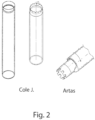
- the first method chosen by the majority of practitioners is to use sharp, even ultra sharp punches.
- the reasoning is as follows: the sharper the punch, the less it will deform the follicle within the skin during step 1 of the follicular extraction, and by decreasing the deformation of the follicular unit they hope to decrease the rate of transection.
- FIG. 2 illustrating punches according to Cole and Artas.
- the follicles almost always have the following characteristic: they are arranged in the shape of a cone.
- the upper end of the cone corresponds to the output of the hair at skin level while its lower base corresponds to the follicular zone of these hairs, as shown in FIG. 1 .
- the follicle is firmly attached to surrounding structures.
- the punch To be able to detach a follicle in order to extract it without damage (Step 2), the punch must be pushed in deep enough; that is to say about 3-4 mm below the epidermis.
- the result of using sharp punches is often transection-that is to say, the full section of one or more of the hairs is cut (transected) and remains captive in the donor zone. This has the effect of reducing the number of transferred hairs and thereby reducing the quality of the surgical intervention.
- the orientation of the sharp punch is also crucial. Indeed, the slightest deviation from the axis of movement causes contact between the cutting portion and the hair, which causes at best a superficial abrasion, called paring, and at worst a full section of hair remaining in the donor zone, called a transection.
- Step 2 it is often necessary to reduce the depth of the incision made with a sharp punch, such as limiting the incision depth to 2 mm below the epidermis, and/or to increase the diameter of the punch to obtain grafts with a low transection rate.
- This has the effect of increasing the size of scars and of damaging the follicles adjacent to the one being extracted.
- Step 2 the extraction process (Step 2) is slowed with a risk of damaging the follicles during extraction. So this lengthens the overall duration of the intervention.
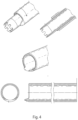
- the second method developed about 15 years ago has been to subdivide Step 1 into two steps with the use of two different punches.
- This second method was named the "3 step” technique.
- the first step is the very superficial cutting of the epidermis with the aid of a sharp punch.
- the second step is to then use a blunt or dull punch to dissect the dermal tissue around the hairs without damaging them.
- the third step is the actual extraction.
- the technique dates from 2004 and was invented by Dr. James Harris.
- FIG. 3 illustrates an example of Dr. Harris' instrument.
- US 2010/082042 A1 discloses a device for harvesting hair follicles according to the preamble of claim 1.
- US 2014/171827 A1 , US 2009/005765 A1 , and US 2009/088776 A1 also disclose tools for harvesting biological tissue samples, e.g. hair follicles.
- US 2016/015963 A1 discloses a device for separating tissue attached to implanted objects, such as leads.
- the invention is defined in claim 1. Further embodiments are defined in the dependent claims. No surgical methods form part of the invention.
- the present invention relates to a device for harvesting all or part of follicles commonly called follicular units.
- the disclosed device includes a hollow tube-like punching tool suitable for producing cores in the scalp.
- distal refers to the end for contacting a skin donor site
- proximal refers to the end away from the skin donor site.
- the terms “internal” and “inner” refer to a portion closer to a central axis of the punch tool, and the terms “external” and “outer” refer to a portion farther away from the central axis of the punch tool.
- the tool terminates distally at a flat end substantially perpendicular to the tube central axis, with the flat end having a non-cutting internal edge and an external sharp cutting edge.
- the edge or edges referred to herein need not be straight or continuous.
- the external sharp cutting edge can be continuous or non-continuous, and rounded or toothed.
- This disclosed tubular tool is commonly called a punch and may be referred to herein as a "hybrid punch.”
- the punch is driven by a dedicated system that includes a foot pedal and a motor. This pedal activates the motor, which is coupled to the punch. This pedal produces oscillation or rotation of the motor and, therefore, movement of the punch.
- the pedal is not a simple on-off switch. Rather it triggers an oscillatory rotation whose speed is proportional to the pedal stroke.
- the tool can be housed in a handpiece or device used in the dental industry and can be capable of being sterilized.
- the disclosed technology can decrease the transection of follicles, i.e., the partial or complete cut of one or more hairs composing this follicle, and thus greatly improve the quality of the FUE hair transplant surgery and the number of harvested grafts.
- the number of missing grafts that is to say, the number of grafts completely transected or buried in the skin, therefore, decreases dramatically.
- an apparatus for harvesting hair follicles from a skin donor site includes a hollow tubular structure having a central axis, an annular ledge attached to an end of the hollow tubular structure and terminating distally at a substantially flat annular face that is substantially in a plane perpendicular to the central axis, and a follicle receiving chamber.
- the annular ledge includes a top surface extending outward from the hollow tubular structure, the flat annular face having a non-cutting inner edge, and a side surface connecting the top surface and the flat annular face and that is at least one of: parallel to the central axis or perpendicular to the flat annular face, where a sharp cutting edge is formed by the connection of the side surface with the flat annular face.
- the follicle receiving chamber extends proximally from the non-cutting inner edge of the substantially flat annular face.
- an apparatus for harvesting hair follicles from a skin donor site by rotating or oscillating motion includes a hollow tubular structure having a central axis, an annular ledge attached to an end of the hollow tubular structure and terminating distally at a substantially flat annular face that is substantially in a plane perpendicular to the central axis, and a follicle receiving chamber.
- the annular ledge includes a top surface extending outward from the hollow tubular structure, the substantially flat annular face having a non-cutting inner edge, and a beveled side surface connecting the top surface and the substantially flat annular face, where a sharp cutting edge is formed by the connection of the beveled side surface with the flat annual face.
- the follicle receiving chamber extends proximally from the non-cutting inner edge of the substantially flat annular face.
- the top surface is substantially perpendicular to the hollow tubular structure.
- a junction formed by the top surface of the annular ledge and an outer wall of the hollow tubular structure is an abrupt angle.
- the follicle receiving chamber is smoothly varying.
- the flat annular face includes notches such that the sharp cutting edge is non-continuous.
- the annular ledge includes teeth between the notches.
- an apparatus for harvesting hair follicles from a skin donor site by rotating or oscillating motion includes a hollow tubular structure having a central axis, a structural skirt attached to an end of the hollow tubular structure and terminating distally at a substantially flat annular face that is substantially in a plane perpendicular to the central axis, and a follicle receiving chamber.
- the structural skirt includes the flat annular face having a non-cutting inner edge, and an inclined surface connecting the tubular structure and the flat annular face, where a sharp cutting edge is formed by the connection of the inclined surface with the flat annual face.
- the follicle receiving chamber extending proximally from the non-cutting inner edge of the substantially flat annular face.
- a junction formed by the inclined surface of the structural skirt and an outer wall of the hollow tubular structure is an abrupt angle.
- the follicle receiving chamber is smoothly varying.
- the flat annular face includes notches such that the sharp cutting edge is non-continuous.
- the structural skirt includes teeth between the notches.
- the disclosed technology relates to hair follicle harvesting system, exemplary method, not forming part of the invention, and apparatus that greatly reduces the rate of transection and missing grafts, even when using smaller diameter punches, and that increases harvesting rate with little or no damage to follicles during the extraction step.
- the system includes various parts.
- a pedal activates a motor, which communicates therewith via a cable or wirelessly.
- a handpiece can be fitted to the motor, and the pedal triggers movement of a punch held in the handpiece via a chuck.
- a tool according to the disclosed technology combines in a single punch two seemingly opposing characteristics: a punch portion sharp enough to penetrate the epidermis easily and at the same time ensuring that this punch is sufficiently gentle so as to reduce damage to the hairs when it plunges into the dermal portion of the skin.
- the disclosed tool positions an annular sharp cutting edge at the outer perimeter of an annular face at the distal end of the tool.
- the annular face at the distal end of the tool is substantially in a plane perpendicular to the central axis of the punch.
- a tool according to various embodiments of the disclosed technology has a hollow tubular structure with a central axis and an end structure that can include various shapes, which will be described in more detail later herein.
- the end structures terminate distally in a substantially flat and ring-like/annular face extending substantially in a plane perpendicular to the central axis.
- the substantially flat annular face has a sharp cutting edge located at the outer perimeter, which can be continuous and substantially circular, or can be non-circular and jagged or tooth-like.
- the term "substantially” is used herein to indicate that a shape, alignment, or other characteristic is intended to have a described property and either may have the exact property or may not have exactly the described property because of manufacturing limitations or defects, wear and tear, or other similar limitations or factors.
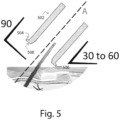
- FIG. 5 illustrates a cross-section of a hollow tubular structure 502 and an end structure 504 of one embodiment of the disclosed punch.
- the end structure 504 is shaped such that its interior appears as a funnel to the hair follicle.
- the cutting edge 506 is located on the outermost edge of the flat annular face 508 of the end structure and is located in a plane that is perpendicular to the central axis A of the hollow tubular structure 502.
- the funnel interior forms a portion of a follicle receiving chamber that extends proximally from a non-cutting inner edge of the flat annular face.
- the flat face 508 of the tool is supported on the skin in such a way that the rotation/oscillation of the tool relative to its central axis will not cut the epidermis when very little pressure is applied.
- the sharp cutting edge 506 is in contact with the epidermis and is capable of marking and cutting the skin during a rotary movement of the tool about its central axis.
- a punch according to the disclosed technology is positioned such that the skin is not approached perpendicularly but obliquely.
- the sharp cutting edge 506 of the end of the punch can therefore easily cut into the epidermis, which, as previously described, can be resistant.
- the movement of the punch can be controlled in order to move it parallel to the axis of the hairs, and therefore the cutting edge 506 also moves in such a way that it is remote from the hair to be harvested and therefore cannot damage the hairs/grafts that are harvested.
- these hairs are directed towards the center of the punch, as in a funnel, and touch the round inner portion of the punch, as shown in FIG.
- the funnel interior forms a portion of a follicle receiving chamber that extends proximally from an inner edge of the flat annular face.
- the follicle receiving chamber is not connected to the sharp cutting edge 506, and thus, hair follicles in the follicle receiving chamber will not be transected by the sharp cutting edge 506.
- the punch can approach the epidermis perpendicularly rather than obliquely, such that the flat annular face 508 contacts the skin, and a sufficient pressure of the punch placed perpendicularly to the skin can cut into the epidermis and provide the same result, as shown in FIG. 6 .
- hybrid punches Because the disclosed punch has both sharp and unsharp characteristics, they are referred to herein as “hybrid punches.” Because the inside of the punch is smooth and/or not aggressive, it is possible to reduce the size of the punch used, and thus to reduce the injuries/scars around the hairs.
- movement of the punch is a slow movement between approximately 60 and 300 revolutions per minute.
- the movement is an oscillating movement such that rotation successively changes direction after having travelled a 30 to 360 degree course.
- the pedal which is included in the disclosed system (discussed below herein) allows one to change the speed of this movement with more or less pressure on the foot pedal.
- the disclosed punch operates to harvest intact human follicular units during a hair transplant surgery.
- the disclosed harvesting tool has some of the beneficial characteristics of conventional sharp punches without being a sharp punch.
- the hybrid punch according to the disclosed technology can be a single piece that is made from the stainless steel. It can include two hollow tubular structures.
- the wider proximal tubular structure (T1) can have an outer diameter of approximately 2.34 mm, which makes it compatible to fit in most dental handpieces.
- the wider proximal tubular structure can serve as a suction chamber and can be housed in a dental handpiece that provides suction.
- the hybrid punch can be housed in a dental handpiece that does not provide suction, and suction can be provided separately from the handpiece.
- the disclosed tool includes a narrower, distal hollow tubular structure (T2) with a central axis and an end structure 3.
- the end structure terminates distally with a substantially flat and annular/ring-like face 4 that extends substantially in a plane perpendicular to the central axis of the punch and having a sharp cutting edge 5 at the outer perimeter of the annular face 4.
- the sharp cutting edge 5 can be substantially circular and continuous.
- the sharp cutting edge 5 can be non-circular and can be jagged or toothed.
- a tool according to the disclosed technology has one or more of the following features.
- the tool includes a central axis, with the annular face 4 at the distal end of the tool.
- each portion of the annular face 4 can be configured to be at an angle relative to the central axis that is between 80 to 100°, or that is between 85 to 95°, as shown in FIG. 20 .
- the angle can be between 87° to 93°.
- the annular face 4 can form any angle in these disclosed ranges relative to the central axis.
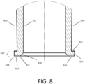
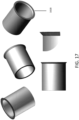
- the annular face 4 can be perpendicular to the central axis, as shown in FIG. 7 .
- the annular or ring-like face 4 has a wall thickness between 50 ⁇ m and 100 ⁇ m, which is the difference between ExTr and IntTr.
- the hollow tubular structure T2 has an external diameter ExDi between 0.7mm and 1.4mm and has a wall thickness between 50 and 150 ⁇ m.
- the external diameter ExTr at the end of the end structure is greater than the outer diameter ExDi of the hollow tubular structure T2 by approximately 50 to 150 ⁇ m.
- the external diameter ExTr at the end of the end structure is greater than the outer diameter ExDi of the hollow tubular structure T2 by no more than 200 ⁇ m.
- the inner edge 10 (InTr) of the flat annular face 4 of the end structure is substantially aligned with the outer surface of the hollow tubular structure T2 with diameter ExDi. Accordingly, the inner edge 10 of the flat annular face 4 of the end structure IntTr therefore has a diameter equal to or close to the diameter ExDi.
- the end structure 3 has a length of less than 1000 ⁇ m . In various embodiments, the end structure 3 has a length between 500 and 300 ⁇ m.
- the end structure 3 has a smoothly curved inner surface 6 that smoothly connects to the inner surface of the hollow tubular structure T2.
- the inner surface 6 of the end structure 3 is substantially in the shape of a half catenoid and forms part of a follicle receiving chamber.
- the outer edge 5 of the annular face 4 of the end structure is a sharp cutting edge.
- the annular face 4 can be beveled to enhance the sharpness of the outer edge, as shown in FIG. 20 .
- the inner edge 10 of the annular face 4 of the end structure is a non-cutting edge and can have a less abrupt angle or can be rounded.
- FIGS. 8-18 show diagrams of various embodiments of the end structures.
- the tools of FIGS. 8-18 include a tubular structure and an end structure that is wider than the tubular structure.
- the tools can be a single piece that is made from stainless steel and that has end portions as illustrated in any of FIGS. 8-18 .
- the single piece can include two hollow tubular structures, as shown, for example, in FIG. 7 .
- the wider proximal tubular structure (T1) can have an outer diameter of approximately 2.34 mm, which makes it compatible to fit in most dental handpieces.
- the wider proximal tubular structure can serve as a suction chamber and can be housed in a dental handpiece that provides suction, as shown in FIG. 21 .
- the tool includes a narrower, distal hollow tubular structure (T2) with a central axis and an end structure as shown in any of FIGS. 8-18 .
- each portion of the substantially annular face at the distal end of the tool can be configured to be at an angle relative to the central axis that is between 80 to 100°, or between 85 to 95°, as shown in FIG. 20 .
- the angle can be between 87° to 93°.
- the flat annular face can be perpendicular to the central axis.
- the end structure is in the shape of an annular ledge 810 having a top surface 812, a side surface 814, and a bottom surface that forms the flat annular face 816 described above.
- the top surface 812 can form a 90° angle or substantially a 90° angle with respect to the outer surface 820 of the tubular structure. In various embodiments, the top surface 812 can form another angle with respect to the outer 820 surface of the tubular structure.
- the top surface 812 of the annular ledge 810 can extend outward from the tubular structure by various widths. For example, in various embodiments, the top surface 812 can have a width between 50 and 100 ⁇ m.
- the side surface 814 connects the top surface 812 and the flat annular face 816 of the end structure.
- the side surface 814 forms a straight connection or substantially a straight connection between the outer edge of the top surface 812 and the outer edge 818 of the flat annular face 816, as shown in FIG. 8 . That is, the cross section of the end structure 810 does not include any curvature along the side surface 814 of the end structure.
- the side surface 814 is parallel or substantially parallel to the central axis of the tubular structure. In various embodiments, the side surface 814 is perpendicular or substantially perpendicular to the flat annular face 816 of the end structure.
- the inner edge 817 of the flat annular face 816 of the end structure can be substantially aligned between the inner wall 822 and outer wall 820 of the hollow tubular structure.
- the end structure includes an inner surface 830 that connects the inner edge 817 of the flat annular face with the inner wall 822 of the tubular structure.
- the inner surface 830 cross section can form a straight line or substantially a straight line, as shown in FIG. 8 .
- the inner surface cross section can include a curvature and/or can smoothly connect the inner edge 817 of the flat annular face with the inner wall 822 of the tubular structure, such as a funnel shape shown in FIG. 5 .
- a follicle receiving chamber extends proximally from the inner edge 817 of the flat annular face 816.
- the outer edge 818 of the flat annular face can be substantially circular and continuous, as shown in FIG. 10 .
- the outer edge 818 can be non-circular and can be discontinuous and toothed, as shown in FIG. 11 .
- FIG. 9 shows various dimensions of various embodiments of the end structure of FIG. 8 .
- the tubular structure can have outer dimensions between 0.4 mm and 1.3 mm, inner dimensions between 0.3 mm and 1.2 mm, and wall thickness between 0.05 mm and 0.15 mm.
- the end structure can be wider than the tubular structure and have outer dimensions between 0.6 mm and 1.4 mm.
- the annular ledge can have a top surface dimension between 0.02 mm and 0.1 mm and a side surface dimension between 0.03 mm and 3mm.
- the dimension from the inner wall of the tubular structure to the outermost edge of the end structure can be between 0.07 mm and 0.25 mm.
- FIG. 10 shows various perspectives of a punch having the end structure of FIG. 8 , including various perspectives of the top surface, the side surface, the flat annular face, and other portions of the punch.
- the cutting edge 818 (the outermost edge) is continuous).
- FIG. 11 shows various perspectives of a punch having the end structure of FIG. 8 with notches 1102 formed in the side surface and in the flat annular face of the annular ledge, but not in the top surface of the annular ledge.
- the notches 1102 form teeth 1104 at the flat annular face, such that the cutting edge 1110 (the outermost edge) of the flat annular face is toothed and discontinuous.
- FIG. 12 shows various perspectives of a punch having the end structure of FIG.
- the notches form teeth at the flat annular face, such that the cutting edge (the outermost edge) of the flat annular face is toothed and discontinuous.
- the notches can vary in dimension and can provide different tooth shapes and different numbers of teeth, such as between 20 to 100 teeth.
- the illustrated embodiments are exemplary, and other variations are contemplated to be within the scope of the present disclosure.
- another end structure is in the shape of an annular ledge 1310 having a top surface 1312, a beveled side surface 1314, and a bottom surface that forms the flat annular face 1316 described above.
- the top surface 1312 can form a 90° angle or substantially a 90° angle with respect to the outer surface 1320 of the tubular structure. In various embodiments, the top surface 1312 can form another angle with respect to the outer surface 1320 of the tubular structure.
- the top surface 1312 of the annular ledge can extend outward from the tubular structure by various widths. For example, in various embodiments, the top surface 1312 can have a width between 10 and 50 ⁇ m.
- the beveled side surface 1314 connects the top surface 1312 and the flat annular face 1316 of the end structure.
- the beveled side surface 1314 forms a straight connection or substantially a straight connection between the outer edge of the top surface 1312 and the outer edge 1318 of the flat annular face, as shown in FIG. 13 . That is, the cross section of the end structure does not include any curvature along the side surface 1314 of the end structure.
- the side surface 1314 of the annular ledge forms a sharp edge 1318 with the flat annular face 1316.
- the angle between the side surface 1314 and the flat annular face 1316 is less than 90°.
- the annular face can be beveled to enhance the sharpness of the outer edge, as shown in FIG. 20 .
- the inner edge 1317 of the flat annular face of the end structure can be substantially aligned between the inner wall 1322 and outer wall 1320 of the hollow tubular structure.
- the end structure includes an inner surface 1330 that connects the inner edge 1317 of the flat annular face with the inner wall 1322 of the tubular structure.
- the inner surface 1330 cross section can form a straight line or substantially a straight line, as shown in FIG. 13 .
- the inner surface 1330 cross section can include a curvature and/or can smoothly connect the inner edge 1317 of the flat annular face with the inner wall 1322 of the tubular structure, such as a funnel shape shown in FIG. 5 .
- a follicle receiving chamber extends proximally from the inner edge 1317 of the flat annular face.
- the outer edge 1318 of the flat annular face can be substantially circular and continuous, as shown in FIG. 14 .
- the outer edge can be non-circular and can be jagged or toothed, as shown in FIG. 15 .
- various of the dimensions described above and/or in FIG. 7 and/or FIG. 9 are applicable to the embodiment of FIG. 13 .
- FIG. 14 shows various perspectives of a punch having the end structure of FIG. 13 , including various perspectives of the top surface, the beveled side surface, the flat annular face, and other portions of the punch.
- the cutting edge 1318 (the outermost edge) is continuous.
- FIG. 15 shows various perspectives of a punch having the end structure of FIG. 13 with notches 1502 formed in the beveled side surface and the flat annular face of the annular ledge, but not in the top surface of the annular ledge.
- the notches 1502 form teeth 1504 at the flat annular face, such that the cutting edge 1510 (the outermost edge) of the flat annular face is toothed and discontinuous.
- the illustrated embodiments are exemplary and variations are contemplated to be within the scope of the present disclosure.
- the notches and teeth can have different dimensions than as illustrated and there can be different numbers of teeth, such as between 20 to 100 teeth.
- the notches can reach the top surface of the annular ledge as well.
- the end structure is in the shape of a structural skirt 1610 having an inclined surface 1614 and a bottom surface that forms the flat annular face 1616 described above.
- the inclined surface 1614 connects the tubular structure and the flat annular face 1616 of the end structure.
- the inclined surface 1614 forms a straight connection or substantially a straight connection between the outer wall 1620 of the tubular structure and the outer edge 1618 of the flat annular face, as shown in FIG. 16 . That is, the cross section of the end structure does not include any curvature along the inclined surface 1614 of the end structure.
- the inclined surface 1614 forms a sharp edge 1618 with the flat annular face 1616.
- the annular face can be beveled to enhance the sharpness of the outer edge, as shown in FIG. 20 .
- the inner edge 1617 of the flat annular face of the end structure can be substantially aligned between the inner wall 1622 and outer wall 1620 of the hollow tubular structure.
- the end structure includes an inner surface 1630 that connects the inner edge 1617 of the flat annular face with the inner wall 1622 of the tubular structure.
- the inner surface 1630 cross section can form a straight line or substantially a straight line, as shown in FIG. 16 .
- the inner surface 1630 can include a curvature and/or can smoothly connect the inner edge 1617 of the flat annular face with the inner wall 1622 of the tubular structure, such as a funnel shape shown in FIG. 5 .
- a follicle receiving chamber extends proximally from the inner edge 1617 of the flat annular face 1616.
- the outer edge 1618 of the flat annular face 1616 can be substantially circular and continuous, as shown in FIG. 17 .
- the outer edge can be non-circular and can be jagged or toothed, as shown in FIG. 18 .
- various of the dimensions described above and/or in FIG. 7 and/or FIG. 9 are applicable to the embodiment of FIG. 16 .
- FIG. 17 shows various perspectives of a punch having the end structure of FIG. 16 , including various perspectives of the inclined surface and the flat annular face, and other portions of the punch.
- the cutting edge 1618 (the outermost edge) is continuous.
- FIG. 18 shows various perspectives of a punch having the end structure of FIG. 16 with notches 1802 formed in the inclined surface and the flat annular face of the structural skirt.
- the notches 1802 form teeth 1804 at the flat annular face, such that the cutting edge 1810 (the outermost edge) of the flat annular face is toothed and discontinuous.
- the illustrated embodiments are exemplary and variations are contemplated to be within the scope of the present disclosure.
- the notches and teeth can have different dimensions than as illustrated and there can be different numbers of teeth, such as between 20 to 100 teeth.
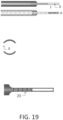
- the hollow tubular structure may have one or more windows 8 that provide a view of the hair to be harvested within the hollow tubular structure.
- two windows 8 opposite each other and positioned 180 degrees apart are arranged on the lower part 2 of the hollow tubular structure just above the end structure.
- the windows of FIG. 19 provide two advantages. As mentioned above, the windows allow a view of the hair and thus allow a user to accurately position the punch around the hairs. Secondly, friction between the hairs and the punch is reduced due to decreased inner surface area because of the windows, thereby allowing the punch to be driven deeper into the dermis while avoiding a phenomenon known as the "missing graft" (graft failure). A missing graft can occur when a conventional punch is inserted too deeply and causes twisting of the follicle, which can lead to a shortening of the latter and to "suction" inside the skin. The graft can disappear completely from the operating field, and it is virtually impossible to recover it.
- the windows of FIG. 19 can apply to any of the embodiments described above herein.
- the disclosed technology can include a suction chamber T1 attached to the hollow tubular structure T2.
- This suction chamber can be connected to a pump (not shown).
- the pump can be located away from the handpiece or attached to the handpiece.
- This suction can aspirate the blood that pools in the holes made in the skin. This also allows lightly suctioning the follicle during extraction and securing it by preventing it from rotating inside the punch.
- the suction chamber of FIG. 21 can apply to any of the embodiments disclosed above herein.
- size indicators such as line or circular markings can, be affixed to the outer surface of the wider tubular structure T1 to indicate the size of the punch to the operator.
- size can correspond to the outer diameter of the flat annular face of the end structure (ExTr). It, therefore, corresponds to the actual size of the hole created by the distal part of the narrower tubular structure (T2).
- the hybrid punches can have the following sizes: size 1: 0.7 mm; size 2: 0.75 mm; size 3: 0.8 mm; size 4: 0.85 mm; size 5: 0.9 mm; size 6: 0.95 mm; size 7: 1 mm; size 8: 1.05 mm; size 9: 1.1 mm; size 11: 1.2 mm.
- Other sizes not expressly stated herein are contemplated and are encompassed by the disclosed technology.
- the thickness of the tubular structure wall is adapted to its diameter.
- the wall thickness can range from 0.08 mm (80 ⁇ m) and 0.12 mm (120 ⁇ m).
- a punch of 0.9 mm will have an external diameter of 0.9 mm for face of the end structure.
- the hollow tubular structure T2 will have an inner diameter of 0.75 mm and an outer diameter of 0.9 mm.
- the tubular structure T2 can include depth indicators 20, such as graduated markings, that indicate the depth at which the punch is located below the surface of the skin.
- depth indicators 20 such as graduated markings, that indicate the depth at which the punch is located below the surface of the skin.
- a marking can be placed every 500 ⁇ m along the outer surface of the tubular structure T2.
- the windows 8 can be positioned just above the end structure and the size of the windows can depend on the size of the tubular structure T2.
- the size of the windows 8 can increase with the diameter of the tubular structure T2.
- a punch of size 0.9 mm can have two windows of size 3mm by 0.6mm.
- FIG. 22 shows exemplary views of different manufacturing tool configurations for shaping the end structure of the tool of FIG. 16 .
- the end portion of the punch tool can initially be manufactured with a lump or block of material, such as stainless steel or another material.
- the shaping tool can be used to remove portions of the lump or block of material to shape it into the end structures disclosed herein, such as the end structures shown in FIGS. 8 , 13 , and 16 .
- the shaping tool has a rounded end portion that contacts the punch material to remove material, and has an angled portion that extends from the rounded end portion.
- the shaping tool can have different sizes for the rounded end portion, including rounded end portion having a 0.2 mm radius or having a 0.05 mm radius.
- the angled portion can form different angles. In FIG. 22 , the angle of the angled portion is 35 degrees, but can be another angle.
- the size of the rounded end portion and the angle of the angled portion of the shaping tool may affect the ultimate shape of the end structure and/or the shape of the junction between the tubular structure and the end structure of the punch. For example, as shown in FIG.
- the size of the rounded end portion of the shaping tool is larger, it may be more difficult to achieve an abrupt angle at the junction between the tubular structure and the end structure of the punch. If the size of the rounded end portion of the shaping tool is smaller, it may be easier to achieve an abrupt angle at the junction between the tubular structure and the end structure of the punch.
- the junction between the tubular structure and the end structure of the punch may be an abrupt angle or may be a gradual transition, such as an arc.
- the junctions are contemplated to be within the scope of the present disclosure.
- FIG. 23 is an illustration of a foot pedal 2300 in accordance with various embodiments of the disclosed technology.
- the pedal includes a top plate 2302 which pivots and can travel a distance of, for example, 5 cm.
- the pedal can control rotation/oscillation of the disclosed punch through a motor (not shown), and the depression of the pedal top plate 2302 enables the rotational/oscillatory speed of the punch to be varied with precision.
- Outlet B provides a port or jack or connection through which the foot pedal can communicate with and power the motor for rotating/oscillating the disclosed punch.
- the foot pedal can communicate wirelessly with the motor, such as by Bluetooth or another wireless protocol, and the motor can have a separate power source.
- the pedal 2300 can include various knobs or buttons or interfaces, each having different functions, as described in the following disclosure.
- the foot pedal 2300 can be powered by a battery (not shown).
- the first button A located below the pedal, allows powering of the motor only when the pedal is actively used.
- button A serves to prevent powering of the motor when the pedal is not actively used.
- the battery is very slightly discharged when the foot pedal 2300 is not actively used. In this manner, the batteries can operate for extended periods without recharging. In various embodiments, the battery can provide power for 72 hours without recharging.
- the foot pedal 2300 can provide an indication that the battery will be imminently discharged, which provides a degree of protection against the complete discharge or depletion of the batteries.
- a red flashing button (not shown) can warn of impending discharge or depletion of the battery and can notify a user to charge the batteries.
- the batteries can be recharged with a charger (not shown) that plugs into the socket F. The plug can be compatible with all regions of the world.
- button C enables the very precise modification of the amount of angular rotation of the punch.
- the disclosed punch can rotate around its axis alternating successively between clockwise rotation and counter-clockwise rotation.
- each clockwise rotation or counter-clockwise rotation can be between 30° and 360°, and button C is used to adjust the number of degrees of this angular rotation in each direction.
- the angular rotation can be more than 360°.
- the rotation/oscillation speed or angular velocity of the punch can be controlled.
- the illustrated graph shows that displacement of the foot pedal can increase the angular velocity of the punch rotation exponentially depending on the intensity of the thrust on the pedal.
- the foot pedal can include different correlations between pedal pressure and the motor driving the rotation/oscillation of the punch, as illustrated.
- Knob D illustrated in FIG. 23 , can be used to modify the correlation or progression curve. In various embodiments, turning the knob D clockwise straightens the curve (for example, 1 towards 2 towards 3) which allows for greater responsiveness of the pedal.
- button E allows adjusting the level of the initial starting speed of the motor. It does not alter the progression of the motor speed as shown in FIG. 24 and is a separate functionality. Button E can be set at the first use and need not be set again unless a different motor is connected.
- a pedal activated by the operator's foot, which launches the rotation/oscillation of the punch and controls it in a precise manner.
- the disclosed system can limit the movements of the punch when necessary.
- a speed between 60 and 300 clockwise-counter-clockwise rotations/oscillations per minute can be achieved with the disclosed system. Then, when the punch penetrates into the deep dermis, the rotational/oscillatory speed can be decreased further.
- the disclosed system also allows, via the adjusting knobs, to change the amount of angular rotation in order to minimize the twisting of the follicle, which results from friction between the graft and the inner part of the punch.
- the recommended amount of angular rotation in the clockwise direction and the counter-clockwise direction is between 30° and 360°, depending on the quality of the skin. It is common to successfully extract a graft with a succession of about a dozen clockwise and counter-clockwise rotations/oscillations.
- the disclosed pedal can include circuitry, processors, microcontrollers, programmable logic devices, ASICS, memory, software, firmware, and/or other software or hardware to perform the disclosed operations.
- the disclosed buttons and knobs on the pedal are exemplary and other interfaces are contemplated, such as switches, slides, and touch screens.
- a punch in accordance with the disclosed technology is capable of extracting between 4000 and 8000 grafts before being replaced.
- a punch according to the disclosed technology can be driven much deeper than a sharp punch of an equivalent diameter, with lesser risk of damage.
- This penetration depth may be equal to the length of a hair follicle, such as between 3 and 5 mm.
- the result is the ability to obtain high quality grafts, with very low transection rate and, at the same time, a higher number of hairs per graft (follicular density) than with a sharp punch of the same diameter.
- the actual extraction step is facilitated because the attachments of the surrounding tissue are more deeply broken than with a sharp punch, which operates more superficially.
- the disclosed system operates significantly faster than prior systems.
- the shortening of the extraction step shortens the total extraction operating time.
- an experienced practitioner can extract up to 600 grafts per hour when the extraction step is separated from the cutting step (that is to say, the cutting step carried out with the punch comes to a stop during the extraction step with another tool or part of a tool).
- the tool according to the disclosed technology can permit hourly follicular extraction rates of around 1000 grafts per hour.
- the use of the disclosed hybrid punches can be particularly effective in cases that are generally difficult to treat. These include extraction of old grafts that are too voluminous, of hair grafts in African patients, and of beard grafts.
- the hair is often spaced further apart from each other than in a conventional situation. Furthermore, the internal micro-scars increase the strength of the attachment of the hair to the surrounding tissue. Among African patients, the hairs are highly curved in the shape of commas and their extraction is often extremely difficult, if not impossible, with the conventional technique of sharp punches. Finally, as to beard hairs, the hairs extracted almost never have lesions.
Landscapes
- Health & Medical Sciences (AREA)
- Life Sciences & Earth Sciences (AREA)
- Surgery (AREA)
- Heart & Thoracic Surgery (AREA)
- Engineering & Computer Science (AREA)
- Biomedical Technology (AREA)
- Nuclear Medicine, Radiotherapy & Molecular Imaging (AREA)
- Medical Informatics (AREA)
- Molecular Biology (AREA)
- Animal Behavior & Ethology (AREA)
- General Health & Medical Sciences (AREA)
- Public Health (AREA)
- Veterinary Medicine (AREA)
- Pathology (AREA)
- Surgical Instruments (AREA)
Applications Claiming Priority (2)
| Application Number | Priority Date | Filing Date | Title |
|---|---|---|---|
| US201862683274P | 2018-06-11 | 2018-06-11 | |
| PCT/US2019/036552 WO2019241247A1 (en) | 2018-06-11 | 2019-06-11 | System, apparatus, and method for follicular unit extraction |
Publications (4)
| Publication Number | Publication Date |
|---|---|
| EP3801311A1 EP3801311A1 (en) | 2021-04-14 |
| EP3801311A4 EP3801311A4 (en) | 2022-03-23 |
| EP3801311C0 EP3801311C0 (en) | 2023-10-04 |
| EP3801311B1 true EP3801311B1 (en) | 2023-10-04 |
Family
ID=68842083
Family Applications (1)
| Application Number | Title | Priority Date | Filing Date |
|---|---|---|---|
| EP19819604.0A Active EP3801311B1 (en) | 2018-06-11 | 2019-06-11 | Apparatus for follicular unit extraction |
Country Status (5)
| Country | Link |
|---|---|
| US (1) | US11957375B2 (es) |
| EP (1) | EP3801311B1 (es) |
| KR (1) | KR20210028184A (es) |
| ES (1) | ES2963424T3 (es) |
| WO (1) | WO2019241247A1 (es) |
Families Citing this family (1)
| Publication number | Priority date | Publication date | Assignee | Title |
|---|---|---|---|---|
| WO2023228112A1 (en) | 2022-05-25 | 2023-11-30 | Saúde Viável S.A. | Extraction tool |
Family Cites Families (11)
| Publication number | Priority date | Publication date | Assignee | Title |
|---|---|---|---|---|
| WO2005109799A2 (en) | 2004-04-08 | 2005-11-17 | Hsc Development Llc | Follicular extraction method and device |
| US7962192B2 (en) * | 2005-09-30 | 2011-06-14 | Restoration Robotics, Inc. | Systems and methods for aligning a tool with a desired location or object |
| US8066717B2 (en) * | 2007-03-19 | 2011-11-29 | Restoration Robotics, Inc. | Device and method for harvesting and implanting follicular units |
| WO2009002677A1 (en) * | 2007-06-26 | 2008-12-31 | Restoration Robotics, Inc. | Follicular unit harvesting tools including devices and their use for severing connective tissue |
| US8226664B2 (en) * | 2008-03-18 | 2012-07-24 | Restoration Robotics, Inc. | Biological unit removal tools with movable retention member |
| US20100082042A1 (en) * | 2008-09-30 | 2010-04-01 | Drews Michael J | Biological unit removal tool with occluding member |
| US9259274B2 (en) | 2008-09-30 | 2016-02-16 | Intuitive Surgical Operations, Inc. | Passive preload and capstan drive for surgical instruments |
| WO2011082130A2 (en) | 2009-12-31 | 2011-07-07 | Umar M D Sanusi | Hair punch |
| US9925366B2 (en) * | 2013-03-15 | 2018-03-27 | The Spectranetics Corporation | Surgical instrument for removing an implanted object |
| BE1024365B1 (fr) | 2016-07-05 | 2018-02-05 | Jean Devroye | Dispositif de prélèvement de greffons "FUE", ainsi que la technique de greffe de cheveux utilisant un tel dispositif |
| KR101993315B1 (ko) | 2019-05-17 | 2019-06-26 | 김광수 | 모발채취용 기능성 썬펀칭 니들 |
-
2019
- 2019-06-11 US US17/251,545 patent/US11957375B2/en active Active
- 2019-06-11 EP EP19819604.0A patent/EP3801311B1/en active Active
- 2019-06-11 ES ES19819604T patent/ES2963424T3/es active Active
- 2019-06-11 KR KR1020217000598A patent/KR20210028184A/ko not_active Application Discontinuation
- 2019-06-11 WO PCT/US2019/036552 patent/WO2019241247A1/en unknown
Also Published As
| Publication number | Publication date |
|---|---|
| US20210251649A1 (en) | 2021-08-19 |
| WO2019241247A1 (en) | 2019-12-19 |
| EP3801311C0 (en) | 2023-10-04 |
| KR20210028184A (ko) | 2021-03-11 |
| EP3801311A4 (en) | 2022-03-23 |
| EP3801311A1 (en) | 2021-04-14 |
| ES2963424T3 (es) | 2024-03-27 |
| US11957375B2 (en) | 2024-04-16 |
Similar Documents
| Publication | Publication Date | Title |
|---|---|---|
| US11849966B2 (en) | System, apparatus, and method for follicular unit extraction | |
| US20180185050A1 (en) | Dissecting punch for follicular extraction and tools and methods using same | |
| JP6319810B2 (ja) | 軟組織にチャネルを形成するための医療装置及び医療アセンブリ | |
| US8202279B2 (en) | Follicular extraction punch and method | |
| KR102216608B1 (ko) | 조직 제거를 위한 의료 디바이스 | |
| US20070213741A1 (en) | Follicular extraction punch and method | |
| KR101716854B1 (ko) | 모발 추출용 핸드피스 | |
| KR101699050B1 (ko) | 모발 추출에 이용되는 펀칭 니들 및 핸드피스 | |
| EP3427677B1 (en) | Punching needle used for hair extraction, and handpiece | |
| EP3801311B1 (en) | Apparatus for follicular unit extraction | |
| KR101990048B1 (ko) | 모발 추출용 펀칭니들 및 핸드피스 | |
| KR20170135532A (ko) | 모발 추출에 이용되는 핸드피스 | |
| KR20180078962A (ko) | 모발 추출에 이용되는 펀칭 니들 및 핸드피스 | |
| US11311310B2 (en) | Fixed depth skin flap elevator device and a method of using the same | |
| EP3781050A1 (en) | Frustoconical hair punch |
Legal Events
| Date | Code | Title | Description |
|---|---|---|---|
| STAA | Information on the status of an ep patent application or granted ep patent |
Free format text: STATUS: THE INTERNATIONAL PUBLICATION HAS BEEN MADE |
|
| STAA | Information on the status of an ep patent application or granted ep patent |
Free format text: STATUS: THE INTERNATIONAL PUBLICATION HAS BEEN MADE |
|
| PUAI | Public reference made under article 153(3) epc to a published international application that has entered the european phase |
Free format text: ORIGINAL CODE: 0009012 |
|
| STAA | Information on the status of an ep patent application or granted ep patent |
Free format text: STATUS: REQUEST FOR EXAMINATION WAS MADE |
|
| 17P | Request for examination filed |
Effective date: 20210108 |
|
| AK | Designated contracting states |
Kind code of ref document: A1 Designated state(s): AL AT BE BG CH CY CZ DE DK EE ES FI FR GB GR HR HU IE IS IT LI LT LU LV MC MK MT NL NO PL PT RO RS SE SI SK SM TR |
|
| AX | Request for extension of the european patent |
Extension state: BA ME |
|
| DAV | Request for validation of the european patent (deleted) | ||
| DAX | Request for extension of the european patent (deleted) | ||
| REG | Reference to a national code |
Ref country code: HK Ref legal event code: DE Ref document number: 40050385 Country of ref document: HK |
|
| A4 | Supplementary search report drawn up and despatched |
Effective date: 20220221 |
|
| RIC1 | Information provided on ipc code assigned before grant |
Ipc: A61B 17/00 20060101ALI20220215BHEP Ipc: A61B 17/322 20060101ALI20220215BHEP Ipc: A61B 17/32 20060101ALI20220215BHEP Ipc: A61B 17/3205 20060101AFI20220215BHEP |
|
| GRAP | Despatch of communication of intention to grant a patent |
Free format text: ORIGINAL CODE: EPIDOSNIGR1 |
|
| STAA | Information on the status of an ep patent application or granted ep patent |
Free format text: STATUS: GRANT OF PATENT IS INTENDED |
|
| INTG | Intention to grant announced |
Effective date: 20230328 |
|
| GRAJ | Information related to disapproval of communication of intention to grant by the applicant or resumption of examination proceedings by the epo deleted |
Free format text: ORIGINAL CODE: EPIDOSDIGR1 |
|
| STAA | Information on the status of an ep patent application or granted ep patent |
Free format text: STATUS: REQUEST FOR EXAMINATION WAS MADE |
|
| RAP1 | Party data changed (applicant data changed or rights of an application transferred) |
Owner name: DEVROYE INSTRUMENTS BELGIUM |
|
| GRAS | Grant fee paid |
Free format text: ORIGINAL CODE: EPIDOSNIGR3 |
|
| STAA | Information on the status of an ep patent application or granted ep patent |
Free format text: STATUS: GRANT OF PATENT IS INTENDED |
|
| GRAP | Despatch of communication of intention to grant a patent |
Free format text: ORIGINAL CODE: EPIDOSNIGR1 |
|
| INTC | Intention to grant announced (deleted) | ||
| GRAA | (expected) grant |
Free format text: ORIGINAL CODE: 0009210 |
|
| STAA | Information on the status of an ep patent application or granted ep patent |
Free format text: STATUS: THE PATENT HAS BEEN GRANTED |
|
| INTG | Intention to grant announced |
Effective date: 20230808 |
|
| AK | Designated contracting states |
Kind code of ref document: B1 Designated state(s): AL AT BE BG CH CY CZ DE DK EE ES FI FR GB GR HR HU IE IS IT LI LT LU LV MC MK MT NL NO PL PT RO RS SE SI SK SM TR |
|
| REG | Reference to a national code |
Ref country code: GB Ref legal event code: FG4D |
|
| REG | Reference to a national code |
Ref country code: CH Ref legal event code: EP |
|
| REG | Reference to a national code |
Ref country code: IE Ref legal event code: FG4D |
|
| REG | Reference to a national code |
Ref country code: DE Ref legal event code: R096 Ref document number: 602019038778 Country of ref document: DE |
|
| U01 | Request for unitary effect filed |
Effective date: 20231024 |
|
| U07 | Unitary effect registered |
Designated state(s): AT BE BG DE DK EE FI FR IT LT LU LV MT NL PT SE SI Effective date: 20231030 |
|
| REG | Reference to a national code |
Ref country code: GR Ref legal event code: EP Ref document number: 20230402243 Country of ref document: GR Effective date: 20240110 |
|
| REG | Reference to a national code |
Ref country code: ES Ref legal event code: FG2A Ref document number: 2963424 Country of ref document: ES Kind code of ref document: T3 Effective date: 20240327 |
|
| PG25 | Lapsed in a contracting state [announced via postgrant information from national office to epo] |
Ref country code: IS Free format text: LAPSE BECAUSE OF FAILURE TO SUBMIT A TRANSLATION OF THE DESCRIPTION OR TO PAY THE FEE WITHIN THE PRESCRIBED TIME-LIMIT Effective date: 20240204 |
|
| PG25 | Lapsed in a contracting state [announced via postgrant information from national office to epo] |
Ref country code: IS Free format text: LAPSE BECAUSE OF FAILURE TO SUBMIT A TRANSLATION OF THE DESCRIPTION OR TO PAY THE FEE WITHIN THE PRESCRIBED TIME-LIMIT Effective date: 20240204 |
|
| PG25 | Lapsed in a contracting state [announced via postgrant information from national office to epo] |
Ref country code: RS Free format text: LAPSE BECAUSE OF FAILURE TO SUBMIT A TRANSLATION OF THE DESCRIPTION OR TO PAY THE FEE WITHIN THE PRESCRIBED TIME-LIMIT Effective date: 20231004 Ref country code: PL Free format text: LAPSE BECAUSE OF FAILURE TO SUBMIT A TRANSLATION OF THE DESCRIPTION OR TO PAY THE FEE WITHIN THE PRESCRIBED TIME-LIMIT Effective date: 20231004 Ref country code: NO Free format text: LAPSE BECAUSE OF FAILURE TO SUBMIT A TRANSLATION OF THE DESCRIPTION OR TO PAY THE FEE WITHIN THE PRESCRIBED TIME-LIMIT Effective date: 20240104 Ref country code: HR Free format text: LAPSE BECAUSE OF FAILURE TO SUBMIT A TRANSLATION OF THE DESCRIPTION OR TO PAY THE FEE WITHIN THE PRESCRIBED TIME-LIMIT Effective date: 20231004 |
|
| REG | Reference to a national code |
Ref country code: DE Ref legal event code: R097 Ref document number: 602019038778 Country of ref document: DE |
|
| PGFP | Annual fee paid to national office [announced via postgrant information from national office to epo] |
Ref country code: GB Payment date: 20240621 Year of fee payment: 6 |
|
| PGFP | Annual fee paid to national office [announced via postgrant information from national office to epo] |
Ref country code: GR Payment date: 20240613 Year of fee payment: 6 |
|
| PG25 | Lapsed in a contracting state [announced via postgrant information from national office to epo] |
Ref country code: CZ Free format text: LAPSE BECAUSE OF FAILURE TO SUBMIT A TRANSLATION OF THE DESCRIPTION OR TO PAY THE FEE WITHIN THE PRESCRIBED TIME-LIMIT Effective date: 20231004 |
|
| PG25 | Lapsed in a contracting state [announced via postgrant information from national office to epo] |
Ref country code: SK Free format text: LAPSE BECAUSE OF FAILURE TO SUBMIT A TRANSLATION OF THE DESCRIPTION OR TO PAY THE FEE WITHIN THE PRESCRIBED TIME-LIMIT Effective date: 20231004 |
|
| PG25 | Lapsed in a contracting state [announced via postgrant information from national office to epo] |
Ref country code: SM Free format text: LAPSE BECAUSE OF FAILURE TO SUBMIT A TRANSLATION OF THE DESCRIPTION OR TO PAY THE FEE WITHIN THE PRESCRIBED TIME-LIMIT Effective date: 20231004 Ref country code: SK Free format text: LAPSE BECAUSE OF FAILURE TO SUBMIT A TRANSLATION OF THE DESCRIPTION OR TO PAY THE FEE WITHIN THE PRESCRIBED TIME-LIMIT Effective date: 20231004 Ref country code: RO Free format text: LAPSE BECAUSE OF FAILURE TO SUBMIT A TRANSLATION OF THE DESCRIPTION OR TO PAY THE FEE WITHIN THE PRESCRIBED TIME-LIMIT Effective date: 20231004 Ref country code: CZ Free format text: LAPSE BECAUSE OF FAILURE TO SUBMIT A TRANSLATION OF THE DESCRIPTION OR TO PAY THE FEE WITHIN THE PRESCRIBED TIME-LIMIT Effective date: 20231004 |
|
| U20 | Renewal fee paid [unitary effect] |
Year of fee payment: 6 Effective date: 20240625 |
|
| PLBE | No opposition filed within time limit |
Free format text: ORIGINAL CODE: 0009261 |
|
| STAA | Information on the status of an ep patent application or granted ep patent |
Free format text: STATUS: NO OPPOSITION FILED WITHIN TIME LIMIT |
|
| PGFP | Annual fee paid to national office [announced via postgrant information from national office to epo] |
Ref country code: TR Payment date: 20240603 Year of fee payment: 6 |
|
| 26N | No opposition filed |
Effective date: 20240705 |