EP3801111B1 - Fluid-filled cushioning article with seamless side walls and method of manufacturing - Google Patents
Fluid-filled cushioning article with seamless side walls and method of manufacturing Download PDFInfo
- Publication number
- EP3801111B1 EP3801111B1 EP19737278.2A EP19737278A EP3801111B1 EP 3801111 B1 EP3801111 B1 EP 3801111B1 EP 19737278 A EP19737278 A EP 19737278A EP 3801111 B1 EP3801111 B1 EP 3801111B1
- Authority
- EP
- European Patent Office
- Prior art keywords
- weld
- polymeric sheet
- side wall
- edge
- wall
- Prior art date
- Legal status (The legal status is an assumption and is not a legal conclusion. Google has not performed a legal analysis and makes no representation as to the accuracy of the status listed.)
- Active
Links
Images





Classifications
-
- B—PERFORMING OPERATIONS; TRANSPORTING
- B29—WORKING OF PLASTICS; WORKING OF SUBSTANCES IN A PLASTIC STATE IN GENERAL
- B29C—SHAPING OR JOINING OF PLASTICS; SHAPING OF MATERIAL IN A PLASTIC STATE, NOT OTHERWISE PROVIDED FOR; AFTER-TREATMENT OF THE SHAPED PRODUCTS, e.g. REPAIRING
- B29C65/00—Joining or sealing of preformed parts, e.g. welding of plastics materials; Apparatus therefor
- B29C65/02—Joining or sealing of preformed parts, e.g. welding of plastics materials; Apparatus therefor by heating, with or without pressure
- B29C65/34—Joining or sealing of preformed parts, e.g. welding of plastics materials; Apparatus therefor by heating, with or without pressure using heated elements which remain in the joint, e.g. "verlorenes Schweisselement"
- B29C65/3404—Joining or sealing of preformed parts, e.g. welding of plastics materials; Apparatus therefor by heating, with or without pressure using heated elements which remain in the joint, e.g. "verlorenes Schweisselement" characterised by the type of heated elements which remain in the joint
- B29C65/3444—Joining or sealing of preformed parts, e.g. welding of plastics materials; Apparatus therefor by heating, with or without pressure using heated elements which remain in the joint, e.g. "verlorenes Schweisselement" characterised by the type of heated elements which remain in the joint being a ribbon, band or strip
- B29C65/3452—Joining or sealing of preformed parts, e.g. welding of plastics materials; Apparatus therefor by heating, with or without pressure using heated elements which remain in the joint, e.g. "verlorenes Schweisselement" characterised by the type of heated elements which remain in the joint being a ribbon, band or strip forming a sleeve, e.g. a wrap-around sleeve
-
- A—HUMAN NECESSITIES
- A43—FOOTWEAR
- A43B—CHARACTERISTIC FEATURES OF FOOTWEAR; PARTS OF FOOTWEAR
- A43B13/00—Soles; Sole-and-heel integral units
- A43B13/14—Soles; Sole-and-heel integral units characterised by the constructive form
- A43B13/18—Resilient soles
- A43B13/20—Pneumatic soles filled with a compressible fluid, e.g. air, gas
-
- B—PERFORMING OPERATIONS; TRANSPORTING
- B29—WORKING OF PLASTICS; WORKING OF SUBSTANCES IN A PLASTIC STATE IN GENERAL
- B29D—PRODUCING PARTICULAR ARTICLES FROM PLASTICS OR FROM SUBSTANCES IN A PLASTIC STATE
- B29D35/00—Producing footwear
- B29D35/12—Producing parts thereof, e.g. soles, heels, uppers, by a moulding technique
- B29D35/14—Multilayered parts
- B29D35/142—Soles
-
- B—PERFORMING OPERATIONS; TRANSPORTING
- B32—LAYERED PRODUCTS
- B32B—LAYERED PRODUCTS, i.e. PRODUCTS BUILT-UP OF STRATA OF FLAT OR NON-FLAT, e.g. CELLULAR OR HONEYCOMB, FORM
- B32B1/00—Layered products having a non-planar shape
-
- B—PERFORMING OPERATIONS; TRANSPORTING
- B32—LAYERED PRODUCTS
- B32B—LAYERED PRODUCTS, i.e. PRODUCTS BUILT-UP OF STRATA OF FLAT OR NON-FLAT, e.g. CELLULAR OR HONEYCOMB, FORM
- B32B27/00—Layered products comprising a layer of synthetic resin
- B32B27/06—Layered products comprising a layer of synthetic resin as the main or only constituent of a layer, which is next to another layer of the same or of a different material
- B32B27/08—Layered products comprising a layer of synthetic resin as the main or only constituent of a layer, which is next to another layer of the same or of a different material of synthetic resin
-
- B—PERFORMING OPERATIONS; TRANSPORTING
- B32—LAYERED PRODUCTS
- B32B—LAYERED PRODUCTS, i.e. PRODUCTS BUILT-UP OF STRATA OF FLAT OR NON-FLAT, e.g. CELLULAR OR HONEYCOMB, FORM
- B32B27/00—Layered products comprising a layer of synthetic resin
- B32B27/30—Layered products comprising a layer of synthetic resin comprising vinyl (co)polymers; comprising acrylic (co)polymers
- B32B27/306—Layered products comprising a layer of synthetic resin comprising vinyl (co)polymers; comprising acrylic (co)polymers comprising vinyl acetate or vinyl alcohol (co)polymers
-
- B—PERFORMING OPERATIONS; TRANSPORTING
- B32—LAYERED PRODUCTS
- B32B—LAYERED PRODUCTS, i.e. PRODUCTS BUILT-UP OF STRATA OF FLAT OR NON-FLAT, e.g. CELLULAR OR HONEYCOMB, FORM
- B32B27/00—Layered products comprising a layer of synthetic resin
- B32B27/40—Layered products comprising a layer of synthetic resin comprising polyurethanes
-
- B—PERFORMING OPERATIONS; TRANSPORTING
- B32—LAYERED PRODUCTS
- B32B—LAYERED PRODUCTS, i.e. PRODUCTS BUILT-UP OF STRATA OF FLAT OR NON-FLAT, e.g. CELLULAR OR HONEYCOMB, FORM
- B32B7/00—Layered products characterised by the relation between layers; Layered products characterised by the relative orientation of features between layers, or by the relative values of a measurable parameter between layers, i.e. products comprising layers having different physical, chemical or physicochemical properties; Layered products characterised by the interconnection of layers
- B32B7/04—Interconnection of layers
- B32B7/05—Interconnection of layers the layers not being connected over the whole surface, e.g. discontinuous connection or patterned connection
-
- B—PERFORMING OPERATIONS; TRANSPORTING
- B32—LAYERED PRODUCTS
- B32B—LAYERED PRODUCTS, i.e. PRODUCTS BUILT-UP OF STRATA OF FLAT OR NON-FLAT, e.g. CELLULAR OR HONEYCOMB, FORM
- B32B2307/00—Properties of the layers or laminate
- B32B2307/70—Other properties
- B32B2307/724—Permeability to gases, adsorption
- B32B2307/7242—Non-permeable
-
- B—PERFORMING OPERATIONS; TRANSPORTING
- B32—LAYERED PRODUCTS
- B32B—LAYERED PRODUCTS, i.e. PRODUCTS BUILT-UP OF STRATA OF FLAT OR NON-FLAT, e.g. CELLULAR OR HONEYCOMB, FORM
- B32B2437/00—Clothing
- B32B2437/02—Gloves, shoes
Definitions
- the present teachings generally relate to a cushioning article and a method of manufacturing a cushioning article.
- Fluid-filled bladders used for cushioning in footwear or other articles provide the advantage of lightweight cushioning and resiliency. Those skilled in the footwear arts strive to simplify manufacturing methods while providing repeatability, reliability, and aesthetically pleasing cushioning articles.
- GB 1 272 601 A discloses a method of manufacturing a cushioning article, wherein the body or tubular part of such a cushioning article is made by wrapping a laminated sheet around a forming mandrel and heat-sealing overlapping portions of the sheet to form a tubular body.
- Cushioning articles that includes sealed, fluid-filled bladders made from sheets of multi-layer polymeric films are typically welded or thermoformed.
- the multiple layers may include one or more gas barrier layers that retain the fluid in the bladder. Because the multiple layers are welded or thermoformed to provide the desired shape of the bladder, weld seams typically are disposed at the periphery of the bladder. If the bladder is exposed for viewing when assembled in the article, it may be more aesthetically pleasing to view a portion of the bladder without weld seams, but it can be difficult to locate the weld seams so that they will not show.
- a method of manufacturing a cushioning article for an article of footwear according to the claimed invention is defined in claim 1.
- Dependent claims 2-11 define advantageous embodiments of the method according to the claimed invention.
- a cushioning article for an article of footwear according to the claimed invention is defined in claim 12.
- Dependent claims 13-15 define advantageous embodiments of the cushioning article according to the claimed invention.
- a method of manufacturing disclosed herein provides a cushioning article that has side walls that are free from any weld seams.
- the method of manufacturing a cushioning article comprises wrapping a polymeric sheet around a support so that the polymeric sheet surrounds a perimeter of the support. A first portion of the polymeric sheet adjacent a first side edge of the polymeric sheet overlaps and is stacked on a second portion of the polymeric sheet adjacent a second side edge of the polymeric sheet.
- the method includes welding the first portion to the second portion at a first weld disposed between the first side edge and the second side edge while the polymeric sheet is wrapped around the support so that the polymeric sheet forms an open-ended sheath with a top wall, a bottom wall, a first side wall and a second side wall with the first weld disposed at only one of the top wall and the bottom wall.
- the polymeric sheet is then removed from the support, and, after removing the polymeric sheet from the support, the top wall is welded to the bottom wall at a first transverse weld and a second transverse weld.
- Both the first transverse weld and the second transverse weld cross the first weld and extend from the first side wall to the second side wall so that the polymeric sheet defines and encloses an interior cavity capable of retaining a fluid, and the first side wall and the second side wall are weld-free.
- the method may include, prior to removing the polymeric sheet from the support, welding the first portion to the second portion at a second weld that is disposed between the first side edge and the second side edge and is spaced apart from the first weld. Welding the first weld may be contemporaneous with welding the second weld.
- the method may include, prior to welding the first weld, knurling at least one of the first portion of the polymeric sheet and the second portion of the polymeric sheet. Knurling one or both portions helps roughen the surface of the polymeric sheet, which may enable a stronger weld seam.
- the first side edge and the second side edge may both extend from a top edge of the polymeric sheet to a bottom edge of the polymeric sheet.
- the method may further comprise, contemporaneously with welding the first transverse weld, welding a first outer weld between the first transverse weld and the top edge.
- the first outer weld may extend from the first side wall to the second side wall, and the polymeric sheet may form a flange extending outward from the first transverse weld to the first outer weld, with the flange having a recess between the first transverse weld and the first outer weld.
- the method may further comprise, contemporaneously with welding the second transverse weld, welding a second outer weld between the second transverse weld and the bottom edge.
- the second outer weld may extend from the first side wall to the second side wall.
- the polymeric sheet may form a flange extending outward from the second transverse weld to the second outer weld, with the flange having a recess between the second transverse weld and the second outer weld.
- the method may further comprise, after welding the polymeric sheet at the first transverse weld and the second transverse weld, trimming the polymeric sheet at the top edge, at the bottom edge, or at both the top edge and the bottom edge. Additionally, the method may include inflating the interior cavity with the fluid and sealing the interior cavity such that the interior cavity retains the fluid.
- the method further comprises welding the top wall to the bottom wall at an intermediate weld that extends across the first weld and terminates inward of each of the first side wall, the second side wall, the first transverse weld, and the second transverse weld.
- Welding the top wall to the bottom wall at the intermediate weld may be contemporaneous with welding the polymeric sheet at the first transverse weld and the second transverse weld.
- the method may further comprise disposing the cushioning article in a footwear sole structure, wherein the footwear sole structure is configured with an opening, and at least one of the first side wall and the second side wall is positioned at the opening. Because the welds are located at the top wall or the bottom wall and not at either of the side walls, no welds will extend across the opening, and the weld-free surface of one of the side walls may be viewable at the opening.
- a cushioning article comprises a polymeric sheet having a first portion overlapped with a second portion and welded to the second portion at a first weld, the first portion adjacent a first side edge of the polymeric sheet and the second portion adjacent a second side edge of the polymeric sheet.
- the polymeric sheet forms a top wall, a bottom wall, a first side wall, and a second side wall.
- the first side wall and the second side wall extend between the top wall and the bottom wall, and the first weld is disposed at only one of the top wall or the bottom wall.
- the polymeric sheet has a first transverse weld at which the top wall is welded to the bottom wall and a second transverse weld at which the top wall is welded to the bottom wall.
- Both the first transverse weld and the second transverse weld cross the first weld and extending from the first side wall to the second side wall so that the polymeric sheet defines and encloses an interior cavity capable of retaining a fluid, and the first side wall and the second side wall are weld-free.
- the cushioning article may include a second weld at which the first portion is welded to the second portion, the second weld disposed between the first side edge and the second side edge and spaced apart from the first weld.
- the first side edge and the second side edge both extend from a top edge of the polymeric sheet to a bottom edge of the polymeric sheet, and a first outer weld is between the first transverse weld and the top edge and extends from the first side wall to the second side wall.
- the polymeric sheet forms a flange extending outward from the first transverse weld to the first outer weld.
- the flange has a recess between the first transverse weld and the first outer weld.
- the cushioning article further comprises a second outer weld between the second transverse weld and the bottom edge and extending from the first side wall to the second side wall.
- the polymeric sheet forms a flange extending outward from the second transverse weld to the second outer weld.
- the flange has a recess between the second transverse weld and the second outer weld.
- the cushioning article further comprises an intermediate weld securing the top wall to the bottom wall and that extends across the first weld and terminates inward of each of the first side wall, the second side wall, the first transverse weld, and the second transverse weld.
- the polymeric sheet comprises a multi-layer polymeric sheet.
- the multi-layer polymeric sheet may be a laminate membrane having at least a first layer comprising a thermoplastic polyurethane, and at least a second layer comprising a gas barrier polymer.
- the gas barrier polymer may be an ethylene-vinyl alcohol copolymer.
- Cushioning articles that includes sealed, fluid-filled bladders made from sheets of multi-layer polymeric films are typically welded or thermoformed.
- the multiple layers may include one or more gas barrier layers that retain the fluid in the bladder. Because the multiple layers are welded or thermoformed to provide the desired shape of the bladder, weld seams typically are disposed at the periphery of the bladder. If the bladder is exposed for viewing when assembled in the article, it may be more aesthetically pleasing to view a portion of the bladder without weld seams, but it can be difficult to locate the weld seams so that they will not show.
- FIG. 1 shows a polymeric sheet 10 that is subjected to the method of manufacturing 100 shown in the flowchart of FIG. 17 to form a cushioning article 12 shown in FIGS. 10-11 .
- the cushioning article 12 has no welds or seams on its side walls. This is difficult to achieve for a cushioning article that is not injection molded.
- the polymeric sheet 10 is a multi-layer sheet and, as such, is not conducive to injection molding.
- the polymeric sheet 10 may be a multi-layer polymeric sheet that is a laminate membrane having at least a first layer 14 comprising a thermoplastic polyurethane, and at least a second layer 16 comprising a gas barrier polymer.
- the sheet includes alternating first layers 14 and second layers 16.
- the sheet 10 can include any of various polymeric materials that can retain a fluid at a predetermined pressure, including a fluid that is a gas, such as air, nitrogen, or another gas.
- the sheet 10 can include thermoplastic polymeric material, such as a urethane, polyurethane, polyester, polyester polyurethane, and/or polyether polyurethane.
- FIG. 13 which is a close-up fragmentary cross-sectional portion of the cushioning article 12 formed from the sheet 10 in an article of footwear 18 taken at lines 13-13 in FIG. 12 , shows that the polymeric sheet 10 is a laminate membrane formed from thin films having one or more first layers 14 that comprise thermoplastic polyurethane layers 14 and that alternate with one or more second layers 16, also referred to herein as barrier layers, gas barrier polymers, or gas barrier layers, that comprise a copolymer of ethylene and vinyl alcohol (EVOH) that is impermeable to the pressurized fluid contained therein as disclosed in U.S. Patent No. 6,082,025 to Bonk et al ..
- One of the first layers 14 may be arranged to form an outer surface of the polymeric sheet 10.
- the outermost first layer 14 shown in FIG. 13 may be a portion of the outer surface of the cushioning article 12.
- the polymeric sheet 10 may also be formed from a material that includes alternating layers of thermoplastic polyurethane and ethylene-vinyl alcohol copolymer, as disclosed in U.S. Patent Nos. 5,713,141 and 5,952,065 to Mitchell et al. .
- the layers may include ethylene-vinyl alcohol copolymer, thermoplastic polyurethane, and a regrind material of the ethylene-vinyl alcohol copolymer and thermoplastic polyurethane.
- the polymeric sheet 10 may also be a flexible microlayer membrane that includes alternating layers of a gas barrier polymer material such as second layers 16 and an elastomeric material such as first layers 14, as disclosed in U.S. Patent Nos. 6,082,025 and 6,127,026 to Bonk al.. Additional suitable materials for the polymeric sheet 10 are disclosed in U.S. Patent Nos. 4,183,156 and 4,219,945 to Rudy . Further suitable materials for the polymeric sheet 10 include thermoplastic films containing a crystalline material, as disclosed in U.S. Patent Nos. 4,936,029 and 5,042,176 to Rudy, and polyurethane including a polyester polyol, as disclosed in U.S. Patent Nos.
- the polymeric sheet 10 begins in a flat, planar configuration, and has a top edge 20, a bottom edge 22, a first side edge 24, and a second side edge 26.
- the side of the sheet 10 facing upward is the inner side of the surface of the cushioning article 12 when manufactured according to the method 100, and so the surface facing upward in FIG. 1 is referred to as the inner surface 28.
- the surface 30 on the opposite side is the outer surface when the cushioning article 12 is manufactured according to the method 100 and is therefore referred to as the outer surface 30.
- the method 100 begins with step 102, in which portions of the polymeric sheet 10 are knurled in preparation for subsequent welding. More specifically, the polymeric sheet 10 has a first portion 32 adjacent the first side edge 24 and a second portion 34 adjacent the second side edge 26. The portions 32, 34 are shown extending from the respective side edges 24, 26 to phantom lines parallel with the side edge. A knurling tool 38 is used to knurl the portions 32, 34. At least the inner surface 28 at the first portion 32 and the outer surface 30 at the second portion 34 are knurled, although the portions 32, 34 may each be knurled at both surfaces 28, 30.
- step 104 wrapping the polymeric sheet 10 around a support 40 so that the polymeric sheet 10 surrounds a perimeter 41 of the support 40, and so that the first portion 32 of the polymeric sheet 10 overlaps and is stacked on the second portion 34 of the polymeric sheet 10.
- Wrapping the polymeric sheet 10 around the support 40 is depicted in FIGS 2 and 3 .
- the polymeric sheet 10 is generally centered under the support 40, and the side edges 24, 26 are moved upward and around the support 40, as indicated by arrows A in FIG. 2 , until the second portion 34 rests on the support 40, and the first portion 32 overlaps and rests on the second portion 34 as shown in FIG. 3 .
- the knurled inner surface 28 at the first portion 32 lays against the knurled outer surface 30 at the second portion 34.
- a first longitudinal weld W1 (also referred to herein as a first weld or a first weld seam) welds the first portion 32 to the second portion 34. Because one or both of the portions 32, 34 are knurled, the material of the sheet 10 may bond together at the weld W1 more strongly than if the surfaces were smoother.
- the method 100 may include step 108, in which, prior to removing the polymeric sheet 10 from the support 40, the first portion 32 is also welded to the second portion 34 at a second weld W2 that is disposed between the first side edge 24 and the second side edge 26 and is spaced apart from the first weld W1.
- Welding the first weld W1 may be contemporaneous with welding the second weld W2, as each may be welded using the same welding tool 42.
- the first and second welds W1, W2 are parallel with one another and with the first and second side edges 24, 26.
- the first and second welds W1, W2 extend from the top edge 20 to the bottom edge 22.
- FIG. 4 shows a welding tool 42 used to create the first weld W1 and the second weld W2.
- Two parallel protrusions 44 of the welding tool 42 create the welds W1, W2 when the welding tool 42 is powered by a power source 46 to provide power for radio frequency welding (also referred to as high frequency or dielectric welding) of the first portion 32 to the second portion 34.
- the power source 46 supplies energy creating an alternating electric field that heats the polymeric sheet 10 at the overlapping portions 32, 34 where the protrusions 44 are applied to the polymeric sheet 10.
- the portions 32, 34 may be secured to one another by another manner of thermal or adhesive bonding.
- step 110 the method 100 proceeds to step 110 in which the polymeric sheet 10 is removed from the support 40. Due to the first and second welds W1, W2, the polymeric sheet 10 forms an open-ended sheath, best shown in FIG. 5 , with a top wall 50, a bottom wall 52, a first side wall 54, and a second side wall 56. The first side wall 54 and the second side wall 56 extend between the top wall 50 and the bottom wall 52.
- the flexible polymeric sheet 10 may almost flatten at the side walls 54, 56 in the state following step 108.
- the polymeric sheet 10 may be referred to as being folded at the side walls 54, 56. However, there are no creases at the side walls 54, 56, but the flexible nature of the polymeric sheet 10 allows it to change direction from the bottom wall to the top wall along the side walls 54, 56 without creasing.
- the polymeric sheet 10 is wrapped around the support 40 during welding, the opposite side of the polymeric sheet 10 is protected from the welding tool 42 by the support 40 and is unaffected by the welding of the first weld W1 and the second weld W2.
- the first weld W1 and the second weld W2 are disposed at only the top wall 50. If the polymeric sheet 10 is instead wrapped around the support 40 from above and welded at a lower side of the support 40, then the first weld W1 and the second weld W2 would be disposed only at the bottom wall 52.
- step 112 in which the top wall 50 is welded to the bottom wall 52 at a first transverse weld TW1 and a second transverse weld TW2, shown in FIG. 7 .
- Both the first transverse weld TW1 and the second transverse weld TW2 cross the first weld W1 and the second weld W2 and extend from the first side wall 54 to the second side wall 56.
- This causes the polymeric sheet 10 to define and encloses an interior cavity 60 capable of retaining a fluid, while leaving the first side wall 54 and the second side wall 56 weld-free, as best shown in FIGS. 10 and 11 .
- the method 100 may further comprise step 114 which may occur contemporaneously with welding the first transverse weld TW1 and the second transverse weld TW2, and includes welding a first outer weld OW1 between the first transverse weld TW1 and the top edge 20, and welding a second outer weld OW2 between the second transverse weld TW2 and the bottom edge 22. More specifically, the parallel protrusions 70 are spaced from one another and from the protrusions 68, further toward the top and bottom edges 20, 22.
- the flange 70A has a recess 72A between the first transverse weld TW1 and the first outer weld OW1.
- Flange 70B has a similar recess 72B between the second transverse weld TW2 and the second outer weld OW2.
- the first transverse weld TW1 and the first outer weld OW1 serve as a double seal of the interior cavity 60 near the top edge 20
- the second transverse weld TW2 and the second outer weld OW2 serve as a double seal of the interior cavity 60 near the bottom edge 22.
- the outer welds OW1 and OW2 provide redundant sealing of the interior cavity 60.
- the recesses 72A and 72B may serve as guides at which the cushioning article 12 may be secured to other components with which it is subsequently assembled, such as a midsole, and upper, etc.
- the method 100 further comprises step 116, welding the top wall 50 to the bottom wall 52 at one or more intermediate welds IW that extends across the first weld W1 and the second weld W1 and terminate inward of each of the first side wall 54, the second side wall 56, the first transverse weld TW1, and the second transverse weld TW2.
- the intermediate welds IW thus do not create sub-chambers within the interior cavity 60.
- Step 116, welding the top wall 50 to the bottom wall 52 at the one or more intermediate welds IW may be contemporaneous with step 112, welding the polymeric sheet at the first transverse weld TW1 and the second transverse weld TW2, and contemporaneous with step 114, welding the first outer weld OW1 and the second outer weld OW2.
- the welding tool 62 includes protrusions 74 that are parallel with and spaced from one another, and are also parallel with and spaced from the protrusions 68, 70 and are generally thicker and shorter than the protrusions 68 and 70.
- the protrusions 74 do not extend to the side walls 54, 56, but extend across the longitudinal welds W1 and W2.
- the protrusions 74 result in intermediate welds IW shown in FIG. 7 that secure the top wall 50 to the bottom wall 52 and the ability of the top control the maximum height H1 of the cushioning article 12 when the cushioning article 12 is inflated, as shown in FIG. 11 , helping it to stay flatter than it would otherwise.
- the method 100 may further comprise, step 118, which occurs after welding the polymeric sheet at the first transverse weld and the second transverse weld, and includes trimming the polymeric sheet 10 at the top edge 20, at the bottom edge 22, or at both the top edge and the bottom edge.
- the trimming occurs between the outward weld OW1 and the top edge 20, and between the outward weld OW2 and the bottom edge 22 and OW2.
- the trimming step is best illustrated in FIG. 9 , where the polymeric sheet 10 has been trimmed to the outward welds OW1 and OW2.
- Apertures 76 have also been punched or otherwise provided at ends of each of the intermediate welds IW, as shown in FIG. 9 .
- step 120 the interior cavity is inflated by filling it with a gas or air to a predetermined pressure. Inflation may occur through an inflation port (not shown) at either flange 70A or 70B provided by a short fill tube laid between the top wall and the bottom wall where the welding tool 62 forms the transverse weld TW1 or TW2 and the corresponding outward weld OW1 or OW2. Alternatively, step 120 can be omitted if the interior cavity 60 is to be at ambient pressure. The inflated interior cavity 60 is subsequently sealed in step 122, such as by sealing the plug.
- the method 100 may move from step 122 to step 124, in which the cushioning article is disposed in a sole structure 80 of the article of footwear 18 of FIG. 12 .
- the sole structure 80 is secured to a footwear upper 19.
- the sole structure 80 has a midsole 82 that is configured with an opening 84, as best illustrated in the cross-section of FIG. 13 .
- Either the first side wall 54 or the second side wall 56 is positioned at the opening 84, depending on the configuration. In the embodiment shown, the first side wall 54 is positioned at the opening 84 so that it is visible through the opening from the exterior of the article of footwear 18. As is evident in FIG.
- welds including longitudinal welds W1, W2, transverse welds TW1, TW2, and outer welds OW1, OW2
- the welds are located at the top wall 50 or the bottom wall 52 and not at either of the side walls 54, 56, no welds will extend across the opening 84, and the weld-free surface of the side wall 54 is viewable at the opening 84.
- FIGS. 14-16 illustrate that multiple cushioning articles 12 may be manufactured from the same single polymeric sheet 10, according to the same method 100.
- Two identical cushioning articles referred to as cushioning articles 12A and 12B are formed according to the same steps described with respect to method 100.
- the first and second longitudinal welds W1 and W2 extend through both of the cushioning articles 12A and 12B.
- the welding tool used has a different pattern of protrusions, and the transverse welds that result near the top edge 20 and the bottom edge 22 are nonlinear.
- the polymeric sheet 10 is turned 90 degrees relative to FIG. 1 in FIG. 14 .
- longitudinal refers to a direction extending a length of a component.
- a longitudinal direction of an article of footwear extends between a forefoot region and a heel region of the article of footwear.
- forward or “anterior” is used to refer to the general direction from a heel region toward a forefoot region
- rearward or “posterior” is used to refer to the opposite direction, i.e., the direction from the forefoot region toward the heel region.
- a component may be identified with a longitudinal axis as well as a forward and rearward longitudinal direction along that axis.
- the longitudinal direction or axis may also be referred to as an anterior-posterior direction or axis.
- transverse refers to a direction extending a width of a component.
- a transverse direction of an article of footwear extends between a lateral side and a medial side of the article of footwear.
- the transverse direction or axis may also be referred to as a lateral direction or axis or a mediolateral direction or axis.
- vertical refers to a direction generally perpendicular to both the lateral and longitudinal directions. For example, in cases where a sole structure is planted flat on a ground surface, the vertical direction may extend from the ground surface upward. It will be understood that each of these directional adjectives may be applied to individual components of a sole structure.
- upward or “upwards” refers to the vertical direction pointing towards a top of the component, which may include an instep, a fastening region and/or a throat of an upper.
- downward or “downwards” refers to the vertical direction pointing opposite the upwards direction, toward the bottom of a component and may generally point towards the bottom of a sole structure of an article of footwear.
- the "interior" of an article of footwear refers to portions at the space that is occupied by a wearer's foot when the article of footwear is worn.
- the “inner side” of a component refers to the side or surface of the component that is (or will be) oriented toward the interior of the component or article of footwear in an assembled article of footwear.
- the “outer side” or “exterior” of a component refers to the side or surface of the component that is (or will be) oriented away from the interior of the article of footwear in an assembled article of footwear. In some cases, other components may be between the inner side of a component and the interior in the assembled article of footwear.
- other components may be between an outer side of a component and the space external to the assembled article of footwear.
- the terms “inward” and “inwardly” refer to the direction toward the interior of the component or article of footwear, such as a shoe
- the terms “outward” and “outwardly” refer to the direction toward the exterior of the component or article of footwear, such as the shoe.
- proximal refers to a direction that is nearer a center of a footwear component, or is closer toward a foot when the foot is inserted in the article of footwear as it is worn by a user.
- distal refers to a relative position that is further away from a center of the footwear component or is further from a foot when the foot is inserted in the article of footwear as it is worn by a user.
- proximal and distal may be understood to provide generally opposing terms to describe relative spatial positions.
Landscapes
- Engineering & Computer Science (AREA)
- Mechanical Engineering (AREA)
- Lining Or Joining Of Plastics Or The Like (AREA)
Description
- This application claims the benefit of priority to
United States Provisional Application No. 62/678,504, filed May 31, 2018 - The present teachings generally relate to a cushioning article and a method of manufacturing a cushioning article.
- Fluid-filled bladders used for cushioning in footwear or other articles provide the advantage of lightweight cushioning and resiliency. Those skilled in the footwear arts strive to simplify manufacturing methods while providing repeatability, reliability, and aesthetically pleasing cushioning articles.
-
GB 1 272 601 A -
-
FIG. 1 is a schematic perspective view of a polymeric sheet and a knurling tool. -
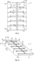
FIG. 2 is a schematic perspective view of the polymeric sheet ofFIG. 1 and a support. -
FIG. 3 is a schematic perspective view of the polymeric sheet ofFIG. 2 wrapped around the support ofFIG. 2 . -
FIG. 4 is a schematic perspective view of the polymeric sheet and support ofFIG. 2 and a first welding tool. -
FIG. 5 is a schematic perspective view of the polymeric sheet removed from the tool after welding with the first welding tool ofFIG. 4 . -
FIG. 6 is a schematic perspective view of the polymeric sheet ofFIG. 5 and a second welding tool. -
FIG. 7 is a schematic top view of the polymeric sheet ofFIG. 6 after welding with the second welding tool. -
FIG. 8 is a schematic fragmentary cross-sectional view of the welded polymeric sheet ofFIG. 7 taken a lines 8-8 inFIG. 7 . -
FIG. 9 is a schematic top view of the welded polymeric sheet ofFIG. 7 after trimming. -
FIG. 10 is a schematic perspective view of the welded polymeric sheet ofFIG. 9 after inflating to form a cushioning article and shows the first side wall. -
FIG. 11 is a schematic perspective view of the welded polymeric sheet ofFIG. 9 after inflating to form the cushioning article and shows the second side wall. -
FIG. 12 is an article of footwear with the cushioning article ofFIG. 11 disposed in a sole structure. -
FIG. 13 is a schematic fragmentary cross-sectional view of the sole structure ofFIG. 12 taken a lines 13-13 inFIG. 12 . -
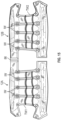
FIG. 14 is a schematic top perspective view of a single sheet welded to form multiple cushioning articles. -
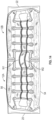
FIG. 15 is a schematic top perspective view of the welded sheet ofFIG. 14 after trimming. -
FIG. 16 is a schematic top perspective view of one of the cushioning articles ofFIG. 15 . -
FIG. 17 is a flow diagram of a method of manufacturing a cushioning article. - Cushioning articles that includes sealed, fluid-filled bladders made from sheets of multi-layer polymeric films are typically welded or thermoformed. The multiple layers may include one or more gas barrier layers that retain the fluid in the bladder. Because the multiple layers are welded or thermoformed to provide the desired shape of the bladder, weld seams typically are disposed at the periphery of the bladder. If the bladder is exposed for viewing when assembled in the article, it may be more aesthetically pleasing to view a portion of the bladder without weld seams, but it can be difficult to locate the weld seams so that they will not show.
- A method of manufacturing a cushioning article for an article of footwear according to the claimed invention is defined in claim 1. Dependent claims 2-11 define advantageous embodiments of the method according to the claimed invention. A cushioning article for an article of footwear according to the claimed invention is defined in
claim 12. Dependent claims 13-15 define advantageous embodiments of the cushioning article according to the claimed invention. A method of manufacturing disclosed herein provides a cushioning
article that has side walls that are free from any weld seams. The method of manufacturing a cushioning article comprises wrapping a polymeric sheet around a support so that the polymeric sheet surrounds a perimeter of the support. A first portion of the polymeric sheet adjacent a first side edge of the polymeric sheet overlaps and is stacked on a second portion of the polymeric sheet adjacent a second side edge of the polymeric sheet. The method includes welding the first portion to the second portion at a first weld disposed between the first side edge and the second side edge while the polymeric sheet is wrapped around the support so that the polymeric sheet forms an open-ended sheath with a top wall, a bottom wall, a first side wall and a second side wall with the first weld disposed at only one of the top wall and the bottom wall. The polymeric sheet is then removed from the support, and, after removing the polymeric sheet from the support, the top wall is welded to the bottom wall at a first transverse weld and a second transverse weld. Both the first transverse weld and the second transverse weld cross the first weld and extend from the first side wall to the second side wall so that the polymeric sheet defines and encloses an interior cavity capable of retaining a fluid, and the first side wall and the second side wall are weld-free. - The method may include, prior to removing the polymeric sheet from the support, welding the first portion to the second portion at a second weld that is disposed between the first side edge and the second side edge and is spaced apart from the first weld. Welding the first weld may be contemporaneous with welding the second weld.
- The method may include, prior to welding the first weld, knurling at least one of the first portion of the polymeric sheet and the second portion of the polymeric sheet. Knurling one or both portions helps roughen the surface of the polymeric sheet, which may enable a stronger weld seam.
- The first side edge and the second side edge may both extend from a top edge of the polymeric sheet to a bottom edge of the polymeric sheet. The method may further comprise, contemporaneously with welding the first transverse weld, welding a first outer weld between the first transverse weld and the top edge. The first outer weld may extend from the first side wall to the second side wall, and the polymeric sheet may form a flange extending outward from the first transverse weld to the first outer weld, with the flange having a recess between the first transverse weld and the first outer weld.
- Similarly, the method may further comprise, contemporaneously with welding the second transverse weld, welding a second outer weld between the second transverse weld and the bottom edge. The second outer weld may extend from the first side wall to the second side wall. The polymeric sheet may form a flange extending outward from the second transverse weld to the second outer weld, with the flange having a recess between the second transverse weld and the second outer weld.
- The method may further comprise, after welding the polymeric sheet at the first transverse weld and the second transverse weld, trimming the polymeric sheet at the top edge, at the bottom edge, or at both the top edge and the bottom edge. Additionally, the method may include inflating the interior cavity with the fluid and sealing the interior cavity such that the interior cavity retains the fluid.
- According to the claimed invention, the method further comprises welding the top wall to the bottom wall at an intermediate weld that extends across the first weld and terminates inward of each of the first side wall, the second side wall, the first transverse weld, and the second transverse weld. Welding the top wall to the bottom wall at the intermediate weld may be contemporaneous with welding the polymeric sheet at the first transverse weld and the second transverse weld. By securing the top wall to the bottom wall between the side walls, the intermediate welds control the maximum height of the bladder when the bladder is inflated, helping it to stay flatter than it would otherwise.
- In one or more embodiments, the method may further comprise disposing the cushioning article in a footwear sole structure, wherein the footwear sole structure is configured with an opening, and at least one of the first side wall and the second side wall is positioned at the opening. Because the welds are located at the top wall or the bottom wall and not at either of the side walls, no welds will extend across the opening, and the weld-free surface of one of the side walls may be viewable at the opening.
- Within the scope of the disclosure a cushioning article comprises a polymeric sheet having a first portion overlapped with a second portion and welded to the second portion at a first weld, the first portion adjacent a first side edge of the polymeric sheet and the second portion adjacent a second side edge of the polymeric sheet. The polymeric sheet forms a top wall, a bottom wall, a first side wall, and a second side wall. The first side wall and the second side wall extend between the top wall and the bottom wall, and the first weld is disposed at only one of the top wall or the bottom wall. The polymeric sheet has a first transverse weld at which the top wall is welded to the bottom wall and a second transverse weld at which the top wall is welded to the bottom wall. Both the first transverse weld and the second transverse weld cross the first weld and extending from the first side wall to the second side wall so that the polymeric sheet defines and encloses an interior cavity capable of retaining a fluid, and the first side wall and the second side wall are weld-free.
- In one or more embodiments, the cushioning article may include a second weld at which the first portion is welded to the second portion, the second weld disposed between the first side edge and the second side edge and spaced apart from the first weld.
- In one or more embodiments of the cushioning article, the first side edge and the second side edge both extend from a top edge of the polymeric sheet to a bottom edge of the polymeric sheet, and a first outer weld is between the first transverse weld and the top edge and extends from the first side wall to the second side wall. The polymeric sheet forms a flange extending outward from the first transverse weld to the first outer weld. The flange has a recess between the first transverse weld and the first outer weld.
- In one or more embodiments, the cushioning article further comprises a second outer weld between the second transverse weld and the bottom edge and extending from the first side wall to the second side wall. The polymeric sheet forms a flange extending outward from the second transverse weld to the second outer weld. The flange has a recess between the second transverse weld and the second outer weld.
- According to the claimed invention, the cushioning article further comprises an intermediate weld securing the top wall to the bottom wall and that extends across the first weld and terminates inward of each of the first side wall, the second side wall, the first transverse weld, and the second transverse weld.
- According to the claimed invention, the polymeric sheet comprises a multi-layer polymeric sheet. The multi-layer polymeric sheet may be a laminate membrane having at least a first layer comprising a thermoplastic polyurethane, and at least a second layer comprising a gas barrier polymer. The gas barrier polymer may be an ethylene-vinyl alcohol copolymer.
- The above features and advantages and other features and advantages of the present teachings are readily apparent from the following detailed description of the modes for carrying out the present teachings when taken in connection with the accompanying drawings.
- Cushioning articles that includes sealed, fluid-filled bladders made from sheets of multi-layer polymeric films are typically welded or thermoformed. The multiple layers may include one or more gas barrier layers that retain the fluid in the bladder. Because the multiple layers are welded or thermoformed to provide the desired shape of the bladder, weld seams typically are disposed at the periphery of the bladder. If the bladder is exposed for viewing when assembled in the article, it may be more aesthetically pleasing to view a portion of the bladder without weld seams, but it can be difficult to locate the weld seams so that they will not show.
- A method of manufacturing 100 disclosed herein provides a cushioning article that has side walls that are free from any weld seams. Referring to the drawings, wherein like reference numbers refer to like components,
FIG. 1 shows apolymeric sheet 10 that is subjected to the method of manufacturing 100 shown in the flowchart ofFIG. 17 to form acushioning article 12 shown inFIGS. 10-11 . Thecushioning article 12 has no welds or seams on its side walls. This is difficult to achieve for a cushioning article that is not injection molded. Thepolymeric sheet 10 is a multi-layer sheet and, as such, is not conducive to injection molding. For example, thepolymeric sheet 10 may be a multi-layer polymeric sheet that is a laminate membrane having at least afirst layer 14 comprising a thermoplastic polyurethane, and at least asecond layer 16 comprising a gas barrier polymer. In the embodiment shown, the sheet includes alternatingfirst layers 14 and second layers 16. Thesheet 10 can include any of various polymeric materials that can retain a fluid at a predetermined pressure, including a fluid that is a gas, such as air, nitrogen, or another gas. For example, thesheet 10 can include thermoplastic polymeric material, such as a urethane, polyurethane, polyester, polyester polyurethane, and/or polyether polyurethane. -
FIG. 13 , which is a close-up fragmentary cross-sectional portion of thecushioning article 12 formed from thesheet 10 in an article offootwear 18 taken at lines 13-13 inFIG. 12 , shows that thepolymeric sheet 10 is a laminate membrane formed from thin films having one or morefirst layers 14 that comprise thermoplastic polyurethane layers 14 and that alternate with one or moresecond layers 16, also referred to herein as barrier layers, gas barrier polymers, or gas barrier layers, that comprise a copolymer of ethylene and vinyl alcohol (EVOH) that is impermeable to the pressurized fluid contained therein as disclosed inU.S. Patent No. 6,082,025 to Bonk et al .. One of thefirst layers 14 may be arranged to form an outer surface of thepolymeric sheet 10. That is, the outermostfirst layer 14 shown inFIG. 13 may be a portion of the outer surface of thecushioning article 12. Thepolymeric sheet 10 may also be formed from a material that includes alternating layers of thermoplastic polyurethane and ethylene-vinyl alcohol copolymer, as disclosed inU.S. Patent Nos. 5,713,141 and5,952,065 to Mitchell et al. . Alternatively, the layers may include ethylene-vinyl alcohol copolymer, thermoplastic polyurethane, and a regrind material of the ethylene-vinyl alcohol copolymer and thermoplastic polyurethane. Thepolymeric sheet 10 may also be a flexible microlayer membrane that includes alternating layers of a gas barrier polymer material such assecond layers 16 and an elastomeric material such asfirst layers 14, as disclosed inU.S. Patent Nos. 6,082,025 and6,127,026 to Bonk al.. Additional suitable materials for thepolymeric sheet 10 are disclosed inU.S. Patent Nos. 4,183,156 and4,219,945 to Rudy . Further suitable materials for thepolymeric sheet 10 include thermoplastic films containing a crystalline material, as disclosed inU.S. Patent Nos. 4,936,029 and5,042,176 to Rudy, and polyurethane including a polyester polyol, as disclosed inU.S. Patent Nos. 6,013,340 ,6,203,868 , and6,321,465 to Bonk et al. . In selecting materials for thepolymeric sheet 10, engineering properties such as tensile strength, stretch properties, fatigue characteristics, dynamic modulus, and loss tangent can be considered. The thickness of thepolymeric sheet 10 used to form thecushioning article 12 can be selected to provide these characteristics. - Referring again to
FIG. 1 , thepolymeric sheet 10 begins in a flat, planar configuration, and has atop edge 20, abottom edge 22, afirst side edge 24, and asecond side edge 26. InFIG. 1 , the side of thesheet 10 facing upward is the inner side of the surface of thecushioning article 12 when manufactured according to themethod 100, and so the surface facing upward inFIG. 1 is referred to as theinner surface 28. Thesurface 30 on the opposite side is the outer surface when thecushioning article 12 is manufactured according to themethod 100 and is therefore referred to as theouter surface 30. - The
method 100 begins withstep 102, in which portions of thepolymeric sheet 10 are knurled in preparation for subsequent welding. More specifically, thepolymeric sheet 10 has afirst portion 32 adjacent thefirst side edge 24 and asecond portion 34 adjacent thesecond side edge 26. Theportions knurling tool 38 is used to knurl theportions inner surface 28 at thefirst portion 32 and theouter surface 30 at thesecond portion 34 are knurled, although theportions surfaces - The
method 100 then proceeds to step 104, wrapping thepolymeric sheet 10 around asupport 40 so that thepolymeric sheet 10 surrounds aperimeter 41 of thesupport 40, and so that thefirst portion 32 of thepolymeric sheet 10 overlaps and is stacked on thesecond portion 34 of thepolymeric sheet 10. Wrapping thepolymeric sheet 10 around thesupport 40 is depicted inFIGS 2 and3 . InFIG. 2 , thepolymeric sheet 10 is generally centered under thesupport 40, and the side edges 24, 26 are moved upward and around thesupport 40, as indicated by arrows A inFIG. 2 , until thesecond portion 34 rests on thesupport 40, and thefirst portion 32 overlaps and rests on thesecond portion 34 as shown inFIG. 3 . In this arrangement, the knurledinner surface 28 at thefirst portion 32 lays against the knurledouter surface 30 at thesecond portion 34. - With the polymeric sheet wrapped on the
support 40 as shown inFIG. 3 , themethod 100 proceeds to step 106, in which a first longitudinal weld W1 (also referred to herein as a first weld or a first weld seam) welds thefirst portion 32 to thesecond portion 34. Because one or both of theportions sheet 10 may bond together at the weld W1 more strongly than if the surfaces were smoother. - The
method 100 may includestep 108, in which, prior to removing thepolymeric sheet 10 from thesupport 40, thefirst portion 32 is also welded to thesecond portion 34 at a second weld W2 that is disposed between thefirst side edge 24 and thesecond side edge 26 and is spaced apart from the first weld W1. Welding the first weld W1 may be contemporaneous with welding the second weld W2, as each may be welded using thesame welding tool 42. The first and second welds W1, W2 are parallel with one another and with the first and second side edges 24, 26. The first and second welds W1, W2 extend from thetop edge 20 to thebottom edge 22. -
FIG. 4 shows awelding tool 42 used to create the first weld W1 and the second weld W2. Twoparallel protrusions 44 of thewelding tool 42 create the welds W1, W2 when thewelding tool 42 is powered by apower source 46 to provide power for radio frequency welding (also referred to as high frequency or dielectric welding) of thefirst portion 32 to thesecond portion 34. Thepower source 46 supplies energy creating an alternating electric field that heats thepolymeric sheet 10 at the overlappingportions protrusions 44 are applied to thepolymeric sheet 10. Alternatively, but not according to the claimed invention, theportions - After
step 108, themethod 100 proceeds to step 110 in which thepolymeric sheet 10 is removed from thesupport 40. Due to the first and second welds W1, W2, thepolymeric sheet 10 forms an open-ended sheath, best shown inFIG. 5 , with atop wall 50, abottom wall 52, afirst side wall 54, and asecond side wall 56. Thefirst side wall 54 and thesecond side wall 56 extend between thetop wall 50 and thebottom wall 52. Theflexible polymeric sheet 10 may almost flatten at theside walls state following step 108. Thepolymeric sheet 10 may be referred to as being folded at theside walls side walls polymeric sheet 10 allows it to change direction from the bottom wall to the top wall along theside walls - Because the
polymeric sheet 10 is wrapped around thesupport 40 during welding, the opposite side of thepolymeric sheet 10 is protected from thewelding tool 42 by thesupport 40 and is unaffected by the welding of the first weld W1 and the second weld W2. The first weld W1 and the second weld W2 are disposed at only thetop wall 50. If thepolymeric sheet 10 is instead wrapped around thesupport 40 from above and welded at a lower side of thesupport 40, then the first weld W1 and the second weld W2 would be disposed only at thebottom wall 52. - With the
polymeric sheet 10 now removed from thesupport 40, the method proceeds to step 112, in which thetop wall 50 is welded to thebottom wall 52 at a first transverse weld TW1 and a second transverse weld TW2, shown inFIG. 7 . Both the first transverse weld TW1 and the second transverse weld TW2 cross the first weld W1 and the second weld W2 and extend from thefirst side wall 54 to thesecond side wall 56. This causes thepolymeric sheet 10 to define and encloses aninterior cavity 60 capable of retaining a fluid, while leaving thefirst side wall 54 and thesecond side wall 56 weld-free, as best shown inFIGS. 10 and11 . -
FIG. 6 shows awelding tool 62 used to create the first transverse weld TW1 and the second transverse weld TW2. Thepolymeric sheet 10 is placed on a welding table 64 and thewelding tool 62 is powered by thepower source 46 to provide power for radio frequency welding. Thepower source 46 supplies energy creating an alternating electric field that heats thepolymeric sheet 10 at the stacked top andbottom walls parallel protrusions 68 of thewelding tool 62 are applied to thetop wall 50 to create the welds TW1, TW2. Theentire cushioning article 12 is formed from thesingle polymeric sheet 10. - Because the
welding tool 62 has additional protrusions, themethod 100 may further comprisestep 114 which may occur contemporaneously with welding the first transverse weld TW1 and the second transverse weld TW2, and includes welding a first outer weld OW1 between the first transverse weld TW1 and thetop edge 20, and welding a second outer weld OW2 between the second transverse weld TW2 and thebottom edge 22. More specifically, theparallel protrusions 70 are spaced from one another and from theprotrusions 68, further toward the top andbottom edges first side wall 54 to thesecond side wall 56. Thepolymeric sheet 10 forms aflange 70A extending outward from the first transverse weld TW1 to the first outer weld OW1 and outward to thetop edge 20. Thepolymeric sheet 10 also forms aflange 70B extending outward from the first transverse weld TW2 to the first outer weld OW2 and outward to thebottom edge 22. As best shown inFIG. 8 , theflange 70A has arecess 72A between the first transverse weld TW1 and the first outer weld OW1.Flange 70B has asimilar recess 72B between the second transverse weld TW2 and the second outer weld OW2. The first transverse weld TW1 and the first outer weld OW1 serve as a double seal of theinterior cavity 60 near thetop edge 20, and the second transverse weld TW2 and the second outer weld OW2 serve as a double seal of theinterior cavity 60 near thebottom edge 22. Stated differently, the outer welds OW1 and OW2 provide redundant sealing of theinterior cavity 60. Therecesses cushioning article 12 may be secured to other components with which it is subsequently assembled, such as a midsole, and upper, etc. - In addition to the transverse welds TW1 and TW2 and the outer welds OW1 and OW2, the
method 100 according to the claimed invention further comprisesstep 116, welding thetop wall 50 to thebottom wall 52 at one or more intermediate welds IW that extends across the first weld W1 and the second weld W1 and terminate inward of each of thefirst side wall 54, thesecond side wall 56, the first transverse weld TW1, and the second transverse weld TW2. The intermediate welds IW thus do not create sub-chambers within theinterior cavity 60.Step 116, welding thetop wall 50 to thebottom wall 52 at the one or more intermediate welds IW may be contemporaneous withstep 112, welding the polymeric sheet at the first transverse weld TW1 and the second transverse weld TW2, and contemporaneous withstep 114, welding the first outer weld OW1 and the second outer weld OW2. As shown inFIG. 6 , thewelding tool 62 includesprotrusions 74 that are parallel with and spaced from one another, and are also parallel with and spaced from theprotrusions protrusions protrusions 74 do not extend to theside walls protrusions 74 result in intermediate welds IW shown inFIG. 7 that secure thetop wall 50 to thebottom wall 52 and the ability of the top control the maximum height H1 of thecushioning article 12 when thecushioning article 12 is inflated, as shown inFIG. 11 , helping it to stay flatter than it would otherwise. - The
method 100 may further comprise,step 118, which occurs after welding the polymeric sheet at the first transverse weld and the second transverse weld, and includes trimming thepolymeric sheet 10 at thetop edge 20, at thebottom edge 22, or at both the top edge and the bottom edge. The trimming occurs between the outward weld OW1 and thetop edge 20, and between the outward weld OW2 and thebottom edge 22 and OW2. The trimming step is best illustrated inFIG. 9 , where thepolymeric sheet 10 has been trimmed to the outward welds OW1 and OW2.Apertures 76 have also been punched or otherwise provided at ends of each of the intermediate welds IW, as shown inFIG. 9 . After trimming instep 118, themethod 100 proceeds to step 120 in which the interior cavity is inflated by filling it with a gas or air to a predetermined pressure. Inflation may occur through an inflation port (not shown) at eitherflange welding tool 62 forms the transverse weld TW1 or TW2 and the corresponding outward weld OW1 or OW2. Alternatively, step 120 can be omitted if theinterior cavity 60 is to be at ambient pressure. The inflatedinterior cavity 60 is subsequently sealed instep 122, such as by sealing the plug. - If the
cushioning article 12 is for an article of footwear, themethod 100 may move fromstep 122 to step 124, in which the cushioning article is disposed in asole structure 80 of the article offootwear 18 ofFIG. 12 . Thesole structure 80 is secured to a footwear upper 19. Thesole structure 80 has amidsole 82 that is configured with anopening 84, as best illustrated in the cross-section ofFIG. 13 . Either thefirst side wall 54 or thesecond side wall 56 is positioned at theopening 84, depending on the configuration. In the embodiment shown, thefirst side wall 54 is positioned at theopening 84 so that it is visible through the opening from the exterior of the article offootwear 18. As is evident inFIG. 12 , because the welds (including longitudinal welds W1, W2, transverse welds TW1, TW2, and outer welds OW1, OW2), are located at thetop wall 50 or thebottom wall 52 and not at either of theside walls opening 84, and the weld-free surface of theside wall 54 is viewable at theopening 84. -
FIGS. 14-16 illustrate thatmultiple cushioning articles 12 may be manufactured from the samesingle polymeric sheet 10, according to thesame method 100. Two identical cushioning articles referred to ascushioning articles method 100. The first and second longitudinal welds W1 and W2 extend through both of thecushioning articles top edge 20 and thebottom edge 22 are nonlinear. Thepolymeric sheet 10 is turned 90 degrees relative toFIG. 1 inFIG. 14 . Excess polymeric material between thetop edge 20 and the first transverse weld W1, between thebottom edge 22 and the second transverse weld W2, and between some of the interior welds IW is trimmed, as shown inFIG. 15 . The twocushioning articles cushioning article 12B) is shown inFIG. 16 . Neither of thecushioning articles side walls - To assist and clarify the description of various embodiments, various terms are defined herein. Unless otherwise indicated, the following definitions apply throughout this specification (including the claims).
- An "article of footwear", a "footwear article of manufacture", and "footwear" may be considered to be both a machine and a manufacture. Assembled, ready to wear footwear articles (e.g., shoes, sandals, boots, etc.), as well as discrete components of footwear articles (such as a midsole, an outsole, an upper component, etc.) prior to final assembly into ready to wear footwear articles, are considered and alternatively referred to herein in either the singular or plural as "article(s) of footwear" or "footwear".
- "A", "an", "the", "at least one", and "one or more" are used interchangeably to indicate that at least one of the items is present. A plurality of such items may be present unless the context clearly indicates otherwise. All numerical values of parameters (e.g., of quantities or conditions) in this specification, unless otherwise indicated expressly or clearly in view of the context, including the appended claims, are to be understood as being modified in all instances by the term "about" whether or not "about" actually appears before the numerical value. "About" indicates that the stated numerical value allows some slight imprecision (with some approach to exactness in the value; approximately or reasonably close to the value; nearly). If the imprecision provided by "about" is not otherwise understood in the art with this ordinary meaning, then "about" as used herein indicates at least variations that may arise from ordinary methods of measuring and using such parameters. In addition, a disclosure of a range is to be understood as specifically disclosing all values and further divided ranges within the range.
- The terms "comprising", "including", and "having" are inclusive and therefore specify the presence of stated features, steps, operations, elements, or components, but do not preclude the presence or addition of one or more other features, steps, operations, elements, or components. As used in this specification, the term "or" includes any one and all combinations of the associated listed items. The term "any of" is understood to include any possible combination of referenced items, including "any one of" the referenced items. The term "any of" is understood to include any possible combination of referenced claims of the appended claims, including "any one of" the referenced claims.
- For consistency and convenience, directional adjectives may be employed throughout this detailed description corresponding to the illustrated embodiments. Those having ordinary skill in the art will recognize that terms such as "above", "below", "upward", "downward", "top", "bottom", etc., may be used descriptively relative to the figures, without representing limitations on the scope of the invention, as defined by the claims.
- The term "longitudinal" refers to a direction extending a length of a component. For example, a longitudinal direction of an article of footwear extends between a forefoot region and a heel region of the article of footwear. The term "forward" or "anterior" is used to refer to the general direction from a heel region toward a forefoot region, and the term "rearward" or "posterior" is used to refer to the opposite direction, i.e., the direction from the forefoot region toward the heel region. In some cases, a component may be identified with a longitudinal axis as well as a forward and rearward longitudinal direction along that axis. The longitudinal direction or axis may also be referred to as an anterior-posterior direction or axis.
- The term "transverse" refers to a direction extending a width of a component. For example, a transverse direction of an article of footwear extends between a lateral side and a medial side of the article of footwear. The transverse direction or axis may also be referred to as a lateral direction or axis or a mediolateral direction or axis.
- The term "vertical" refers to a direction generally perpendicular to both the lateral and longitudinal directions. For example, in cases where a sole structure is planted flat on a ground surface, the vertical direction may extend from the ground surface upward. It will be understood that each of these directional adjectives may be applied to individual components of a sole structure. The term "upward" or "upwards" refers to the vertical direction pointing towards a top of the component, which may include an instep, a fastening region and/or a throat of an upper. The term "downward" or "downwards" refers to the vertical direction pointing opposite the upwards direction, toward the bottom of a component and may generally point towards the bottom of a sole structure of an article of footwear.
- The "interior" of an article of footwear, such as a shoe, refers to portions at the space that is occupied by a wearer's foot when the article of footwear is worn. The "inner side" of a component refers to the side or surface of the component that is (or will be) oriented toward the interior of the component or article of footwear in an assembled article of footwear. The "outer side" or "exterior" of a component refers to the side or surface of the component that is (or will be) oriented away from the interior of the article of footwear in an assembled article of footwear. In some cases, other components may be between the inner side of a component and the interior in the assembled article of footwear. Similarly, other components may be between an outer side of a component and the space external to the assembled article of footwear. Further, the terms "inward" and "inwardly" refer to the direction toward the interior of the component or article of footwear, such as a shoe, and the terms "outward" and "outwardly" refer to the direction toward the exterior of the component or article of footwear, such as the shoe. In addition, the term "proximal" refers to a direction that is nearer a center of a footwear component, or is closer toward a foot when the foot is inserted in the article of footwear as it is worn by a user. Likewise, the term "distal" refers to a relative position that is further away from a center of the footwear component or is further from a foot when the foot is inserted in the article of footwear as it is worn by a user. Thus, the terms proximal and distal may be understood to provide generally opposing terms to describe relative spatial positions.
- While various embodiments have been described, the description is intended to be exemplary, rather than limiting and it will be apparent to those of ordinary skill in the art that many more embodiments and implementations are possible that are within the scope of the embodiments. Any feature of any embodiment may be used in combination with or substituted for any other feature or element in any other embodiment unless specifically restricted. Accordingly, the embodiments are not to be restricted except in light of the attached claims. Also, various modifications and changes may be made within the scope of the attached claims.
- While several modes for carrying out the many aspects of the present teachings have been described in detail, those familiar with the art to which these teachings relate will recognize various alternative aspects for practicing the present teachings that are within the scope of the appended claims. It is intended that all matter contained in the above description or shown in the accompanying drawings shall be interpreted as illustrative and exemplary of the entire range of alternative embodiments that an ordinarily skilled artisan would recognize as implied by, structurally and/or functionally equivalent to, or otherwise rendered obvious based upon the included content, and not as limited solely to those explicitly depicted and/or described embodiments.
Claims (15)
- A method of manufacturing (100) a cushioning article (12) for an article of footwear (18), the method (100) comprising:wrapping a multi-layer polymeric sheet (10) around a support (40) so that the polymeric sheet (10) surrounds a perimeter (41) of the support (40) and a first portion (32) of the polymeric sheet (10) adjacent a first side edge (24) of the polymeric sheet (10) overlaps and is stacked on a second portion (34) of the polymeric sheet (10) adjacent a second side edge (26) of the polymeric sheet (10);welding the first portion (32) to the second portion (34) at a first weld (W1) disposed between the first side edge (24) and the second side edge (26) while the polymeric sheet (10) is wrapped around the support (40) so that the polymeric sheet (10) forms an open-ended sheath with a top wall (50), a bottom wall (52), a first side wall (54) and a second side wall (56) and with the first weld (W1) disposed at only one of the top wall (50) and the bottom wall (52);removing the polymeric sheet (10) from the support (40);after removing the polymeric sheet (10) from the support (40), welding the top wall (50) to the bottom wall (52) at a first transverse weld (TW1) and a second transverse weld (TW2), both the first transverse weld (TW1) and the second transverse weld (TW2) crossing the first weld (W1) and extending from the first side wall (54) to the second side wall (56) so that the polymeric sheet (10) defines and encloses an interior cavity (60) capable of retaining a fluid, and the first side wall (54) and the second side wall (56) are weld-free; andwelding the top wall (50) to the bottom wall (52) at an intermediate weld (IW) that extends across the first weld (W1) and terminates inward of each of the first side wall (54), the second side wall (56), the first transverse weld (TW1), and the second transverse weld (TW2).
- The method (100) of claim 1, further comprising:
before removing the polymeric sheet (10) from the support (40), welding the first portion (32) to the second portion (34) at a second weld (W2); wherein the second weld (W2) is disposed between the first side edge (24) and the second side edge (26) and is spaced apart from the first weld. - The method of claim 2, wherein welding the first weld is contemporaneous with welding the second weld.
- The method (100) of any of claims 1-3, further comprising:
prior to welding the first weld (W1), knurling at least one of the first portion (32) of the polymeric sheet (10) and the second portion (34) of the polymeric sheet (10). - The method (100) of any of claims 1-4, wherein the first side edge (24) and the second side edge (26) both extend from a top edge (20) of the polymeric sheet (10) to a bottom edge (22) of the polymeric sheet (10), and the method (100) further comprising:
contemporaneously with welding the first transverse weld (TW1), welding a first outer weld (OW1) between the first transverse weld (TW1) and the top edge (20), the first outer weld (OW1) extending from the first side wall (54) to the second side wall (56), the polymeric sheet (10) forming a flange (70A) extending outward from the first transverse weld (TW1) to the first outer weld (OW1), and the flange (70A) having a recess (72A) between the first transverse weld (TW1) and the first outer weld (OW1). - The method (100) of any of claims 1-5, wherein the first side edge (24) and the second side edge (26) both extend from a top edge (20) of the polymeric sheet (10) to a bottom edge (22) of the polymeric sheet (10), and the method (100) further comprising:
contemporaneously with welding the second transverse weld (TW2), welding a second outer weld (OW2) between the second transverse weld (TW2) and the bottom edge (22), the second outer weld (OW2) extending from the first side wall (54) to the second side wall (56), the polymeric sheet (10) forming a flange (70B) extending outward from the second transverse weld (TW2) to the second outer weld (OW2), and the flange (70B) having a recess (72B) between the second transverse weld (TW2) and the second outer weld (OW2). - The method (100) of any of claims 1-6, wherein the first side edge (24) and the second side edge (26) both extend from a top edge (20) of the polymeric sheet (10) to a bottom edge (22) of the polymeric sheet (10), and the method (100) further comprising:
after welding the polymeric sheet (10) at the first transverse weld (TW1) and the second transverse weld (TW2), trimming the polymeric sheet (10) at the top edge (20), at the bottom edge (22), or at both the top edge (20) and the bottom edge (22). - The method (100) of any of claims 1-7, further comprising:
inflating the interior cavity (60) with the fluid. - The method (100) of any of claims 1-8, further comprising:
sealing the interior cavity (60) such that the interior cavity (60) retains the fluid. - The method (100) of claim 1, wherein welding the top wall (50) to the bottom wall (52) at the intermediate weld (IW) is contemporaneous with welding the polymeric sheet (10) at the first transverse weld (TW1) and the second transverse weld (TW2).
- The method (100) of any one of claims 1 to 10, further comprising:
disposing the cushioning article (12) in a footwear sole structure (80); wherein the footwear sole structure (80) is configured with an opening (84), and at least one of the first side wall (54) and the second side wall (56) is positioned at the opening (84). - A cushioning article (12) for an article of footwear (18) comprising:a multi-layer polymeric sheet (10) having a first portion (32) overlapped with a second portion (34) and welded to the second portion (34) at a first weld (W1), the first portion (32) adjacent a first side edge (24) of the polymeric sheet (10) and the second portion (34) adjacent a second side edge (26) of the polymeric sheet (10);the polymeric sheet (10) forming a top wall (50), a bottom wall (52), a first side wall (54), and a second side wall (56), the first side wall (54) and the second side wall (56) extending between the top wall (50) and the bottom wall (52), the first weld (W1) disposed at only one of the top wall (50) or the bottom wall (52);the polymeric sheet (10) having a first transverse weld (TW1) at which the top wall (50) is welded to the bottom wall (52) and a second transverse weld (TW2) at which the top wall (50) is welded to the bottom wall (52), both the first transverse weld (TW1) and the second transverse weld (TW2) crossing the first weld (W1) and extending from the first side wall (54) to the second side wall (56) so that the polymeric sheet (10) defines and encloses an interior cavity (60) capable of retaining a fluid, and the first side wall (54) and the second side wall (56) are weld-free; andan intermediate weld (IW) securing the top wall (50) to the bottom wall (52), extending across the first weld (W1), and terminating inward of each of the first side wall (54), the second side wall (56), the first transverse weld (TW1), and the second transverse weld (TW2).
- The cushioning article (12) of claim 12, further comprising:
a second weld (W2) at which the first portion (32) is welded to the second portion (34), the second weld (W2) disposed between the first side edge (24) and the second side edge (26) and spaced apart from the first weld (W1). - The cushioning article (12) of claim 12 or 13, wherein the first side edge (24) and the second side edge (26) both extend from a top edge (20) of the polymeric sheet (10) to a bottom edge (22) of the polymeric sheet (10), and the cushioning article (12) further comprising:a first outer weld (OW1) between the first transverse weld (TW1) and the top edge (20) and extending from the first side wall (54) to the second side wall (56), the polymeric sheet (10) forming a flange (70A) extending outward from the first transverse weld (TW1) to the first outer weld (OW1), and the flange (70A) having a recess (72A) between the first transverse weld (TW1) and the first outer weld (OW1), andoptionally a second outer weld (OW2) between the second transverse weld (TW2) and the bottom edge (22) and extending from the first side wall (54) to the second side wall (56), the polymeric sheet (10) forming a flange (70B) extending outward from the second transverse weld (TW2) to the second outer weld (OW2), and the flange (70B) having a recess (72B) between the second transverse weld (TW2) and the second outer weld (OW2).
- The cushioning article (12) of claim 12, wherein the multi-layer polymeric sheet is a laminate membrane having:at least a first layer (14) comprising a thermoplastic polyurethane; andat least a second layer (16) comprising a gas barrier polymer,wherein optionally the gas barrier polymer is an ethylene-vinyl alcohol copolymer.
Applications Claiming Priority (2)
| Application Number | Priority Date | Filing Date | Title |
|---|---|---|---|
| US201862678504P | 2018-05-31 | 2018-05-31 | |
| PCT/US2019/034502 WO2019232118A1 (en) | 2018-05-31 | 2019-05-30 | Fluid-filled cushioning article with seamless side walls and method of manufacturing |
Publications (2)
| Publication Number | Publication Date |
|---|---|
| EP3801111A1 EP3801111A1 (en) | 2021-04-14 |
| EP3801111B1 true EP3801111B1 (en) | 2024-12-11 |
Family
ID=67211806
Family Applications (1)
| Application Number | Title | Priority Date | Filing Date |
|---|---|---|---|
| EP19737278.2A Active EP3801111B1 (en) | 2018-05-31 | 2019-05-30 | Fluid-filled cushioning article with seamless side walls and method of manufacturing |
Country Status (5)
| Country | Link |
|---|---|
| US (2) | US11318684B2 (en) |
| EP (1) | EP3801111B1 (en) |
| KR (1) | KR102468094B1 (en) |
| CN (2) | CN115211636A (en) |
| WO (1) | WO2019232118A1 (en) |
Families Citing this family (1)
| Publication number | Priority date | Publication date | Assignee | Title |
|---|---|---|---|---|
| CN119173169A (en) * | 2022-05-11 | 2024-12-20 | 耐克创新有限合伙公司 | Footwear with external reinforcing fluid-filled bladder |
Citations (5)
| Publication number | Priority date | Publication date | Assignee | Title |
|---|---|---|---|---|
| US20040117925A1 (en) * | 2002-12-18 | 2004-06-24 | Lee Yong Koo | Method for manufacturing shoes and shoes manufactured by the method |
| CN102850611A (en) * | 2012-09-24 | 2013-01-02 | 吴江市信许塑料鞋用配套有限公司 | Preparation method of anti-slip sole material |
| CN102850644A (en) * | 2012-09-24 | 2013-01-02 | 吴江市信许塑料鞋用配套有限公司 | Preparation method of wear-resistant foam sole material |
| CN102863604A (en) * | 2012-09-24 | 2013-01-09 | 吴江市信许塑料鞋用配套有限公司 | Preparation method of high-elasticity foaming sole materials |
| KR101457841B1 (en) * | 2014-01-08 | 2014-11-05 | 유흥상 | decorating layer product method of shoe midsole |
Family Cites Families (70)
| Publication number | Priority date | Publication date | Assignee | Title |
|---|---|---|---|---|
| US2748401A (en) * | 1952-06-30 | 1956-06-05 | Hedwin Corp | Extruded flexible and hollow articles and method of making same |
| US2677906A (en) | 1952-08-14 | 1954-05-11 | Reed Arnold | Cushioned inner sole for shoes and meth od of making the same |
| US3291085A (en) | 1964-08-14 | 1966-12-13 | Levy David | Method of sewing a footwear construction |
| US3431570A (en) | 1967-04-11 | 1969-03-11 | Usm Corp | Methods of making welted and outsoled true moccasins |
| US3475836A (en) | 1968-02-29 | 1969-11-04 | Harry Brahm | Air pumping insert for shoes |
| US3556318A (en) | 1968-03-13 | 1971-01-19 | Int Paper Co | Dunnage bag |
| GB1272601A (en) * | 1969-03-28 | 1972-05-03 | Lectratube Ltd | Manufacture of collapsible tubes |
| US3593436A (en) | 1969-05-29 | 1971-07-20 | Hyde Athletic Ind Inc | Athletic shoe sole |
| US4183156A (en) | 1977-01-14 | 1980-01-15 | Robert C. Bogert | Insole construction for articles of footwear |
| US4219945B1 (en) | 1978-06-26 | 1993-10-19 | Robert C. Bogert | Footwear |
| US4367599A (en) | 1980-10-16 | 1983-01-11 | Diamant Frederick J | Shoe sole structure having controlled slippage |
| US4809447A (en) | 1987-11-13 | 1989-03-07 | W. L. Gore & Associates, Inc. | Waterproof breathable sock |
| US4936029A (en) * | 1989-01-19 | 1990-06-26 | R. C. Bogert | Load carrying cushioning device with improved barrier material for control of diffusion pumping |
| US5042176A (en) * | 1989-01-19 | 1991-08-27 | Robert C. Bogert | Load carrying cushioning device with improved barrier material for control of diffusion pumping |
| AT398157B (en) | 1990-11-21 | 1994-10-25 | M & C Oswald Gmbh | SHOE WITH A MULTI-LAYER INSOLE, INSOLE FOR SUCH A SHOE AND METHOD FOR PRODUCING AN INSOLE |
| US5500067A (en) | 1991-10-01 | 1996-03-19 | Jenkner; Brian D. | Apparatus and methods for forming, filling and sealing fluid filled cavities |
| US6258421B1 (en) | 1993-07-23 | 2001-07-10 | Nike, Inc. | Bladder and method of making the same |
| US5952065A (en) | 1994-08-31 | 1999-09-14 | Nike, Inc. | Cushioning device with improved flexible barrier membrane |
| US5664343A (en) | 1995-05-19 | 1997-09-09 | The Rockport Company, Inc. | Shoe having a waterproof liner |
| CZ295382B6 (en) | 1995-06-07 | 2005-07-13 | Nike International, Ltd. | Membrane forming a wall of a hollow object and process for producing thereof |
| US6013340A (en) | 1995-06-07 | 2000-01-11 | Nike, Inc. | Membranes of polyurethane based materials including polyester polyols |
| DE19641842A1 (en) | 1996-10-10 | 1998-04-16 | Adidas Ag | Manufacturing process for footwear |
| US5993585A (en) | 1998-01-09 | 1999-11-30 | Nike, Inc. | Resilient bladder for use in footwear and method of making the bladder |
| US6082025A (en) | 1998-09-11 | 2000-07-04 | Nike, Inc. | Flexible membranes |
| US6127026A (en) | 1998-09-11 | 2000-10-03 | Nike, Inc. | Flexible membranes |
| US6524292B1 (en) | 1999-08-31 | 2003-02-25 | Kimberly-Clark Worldwide, Inc. | Three dimensional body-conforming bladder for an absorbent article |
| US6571490B2 (en) * | 2000-03-16 | 2003-06-03 | Nike, Inc. | Bladder with multi-stage regionalized cushioning |
| US6385864B1 (en) | 2000-03-16 | 2002-05-14 | Nike, Inc. | Footwear bladder with controlled flex tensile member |
| US6402879B1 (en) * | 2000-03-16 | 2002-06-11 | Nike, Inc. | Method of making bladder with inverted edge seam |
| US20050167029A1 (en) * | 2001-11-26 | 2005-08-04 | Nike, Inc. | Method of thermoforming a fluid-filled bladder |
| ES2240591T3 (en) | 2002-03-01 | 2005-10-16 | Sympatex Technologies Gmbh | MANUFACTURING PROCEDURE OF A SEALED SHOES AND SEALED SHOES |
| US20040049942A1 (en) | 2002-09-18 | 2004-03-18 | Eddie Chen | Shoe having waterproof breathable shell |
| DE10300012A1 (en) | 2003-01-02 | 2004-07-22 | W.L. Gore & Associates Gmbh | Waterproof footwear with an elastic connecting band |
| US7055267B2 (en) | 2003-04-30 | 2006-06-06 | Bha Technologies, Inc. | Waterproof footwear construction |
| ITVI20040066A1 (en) | 2004-03-26 | 2004-06-26 | Cunial S R L Flli | METHOD FOR THE APPLICATION OF REINFORCEMENT INSOLES TO THE UPPER OF A FOOTWEAR AND REINFORCEMENT INSOLE SUITABLE TO REALIZE THE APPLICATION METHOD |
| US7752772B2 (en) | 2006-01-24 | 2010-07-13 | Nike, Inc. | Article of footwear having a fluid-filled chamber with flexion zones |
| FR2903866B1 (en) | 2006-07-21 | 2009-03-20 | Salomon Sa | RESPIRO-SEALED SHOE |
| EP2076231A4 (en) | 2006-10-27 | 2012-04-11 | Osim Int Ltd | An air bag and an apparatus and system having the same |
| US7836609B2 (en) | 2007-04-09 | 2010-11-23 | Columbia Insurance Company | Method and apparatus for a shoe with improved construction |
| US8490297B2 (en) | 2007-10-11 | 2013-07-23 | Ginger Guerra | Integrated, cumulative-force-mitigating apparatus, system, and method for substantially-inclined shoes |
| US9408773B2 (en) | 2007-10-26 | 2016-08-09 | Global Monitors, Inc. | Compression vest for patients undergoing hemodialysis and in critical care |
| US8341857B2 (en) * | 2008-01-16 | 2013-01-01 | Nike, Inc. | Fluid-filled chamber with a reinforced surface |
| US8087187B2 (en) | 2008-11-06 | 2012-01-03 | Nike, Inc. | Article of footwear with support assemblies |
| EP2379420B1 (en) | 2008-11-10 | 2015-10-28 | Eco.logic Brands | Thermoformed liquid-holding vessels |
| US20100180466A1 (en) | 2009-01-22 | 2010-07-22 | Shu Tzu Ho | Stitch-down shoe and method for making the same |
| FR2952790B1 (en) | 2009-11-23 | 2012-01-06 | Salomon Sas | IMPROVED SHOE SHOE |
| FR2958508B1 (en) | 2010-04-13 | 2012-06-01 | Decathlon Sa | FIRST FOR FOOTWEAR |
| US8470113B2 (en) * | 2010-05-12 | 2013-06-25 | Nike, Inc. | Method of manufacturing a contoured fluid-filled chamber with a tensile member |
| US8595878B2 (en) | 2010-08-02 | 2013-12-03 | Nike, Inc. | Method of lasting an article of footwear |
| US8968508B2 (en) | 2011-01-17 | 2015-03-03 | Nike, Inc. | Joining polymeric materials |
| US8839530B2 (en) | 2011-04-12 | 2014-09-23 | Nike, Inc. | Method of lasting an article of footwear with a fluid-filled chamber |
| CN102726886B (en) | 2011-04-14 | 2015-02-25 | 许月清 | Cloth sole structure |
| US8595956B2 (en) | 2011-09-29 | 2013-12-03 | C. & J. Clark International Limited | Footwear with elastic footbed cover and soft foam footbed |
| US20130232818A1 (en) | 2012-03-07 | 2013-09-12 | W.L. Gore & Associates, Inc. | Strobel Footwear Construction |
| US20130232825A1 (en) | 2012-03-07 | 2013-09-12 | W. L. Gore & Associates, Inc. | Stretchable Insole |
| US9155357B2 (en) | 2012-09-11 | 2015-10-13 | Nike, Inc. | Automated strobel printing |
| US9788608B2 (en) | 2013-02-13 | 2017-10-17 | Nike, Inc. | Shoe upper having multiple weld zones |
| EP3048998A4 (en) | 2013-09-27 | 2017-07-19 | Kosiorek, Christopher B. | A pneumatic tourniquet apparatus and method of use |
| US9427043B2 (en) | 2013-10-31 | 2016-08-30 | Nike, Inc. | Fluid-filled chamber with stitched tensile member |
| MX385019B (en) | 2014-02-24 | 2025-03-04 | Pregis Innovative Packaging Llc | INFLATABLE FILM HANDLING DEVICE. |
| US9468258B2 (en) | 2014-03-14 | 2016-10-18 | Wolverine Outdoors, Inc. | Footwear including combination lasting construction |
| WO2015200713A1 (en) | 2014-06-25 | 2015-12-30 | Fuerst Group, Inc. | Strobel lasted injected footwear |
| US9474326B2 (en) | 2014-07-11 | 2016-10-25 | Nike, Inc. | Footwear having auxetic structures with controlled properties |
| EP3280282B1 (en) * | 2015-04-08 | 2020-12-16 | NIKE Innovate C.V. | Article including a bladder element with an image and method of manufacturing the article |
| CN107404977B (en) * | 2015-04-08 | 2021-03-09 | 耐克创新有限合伙公司 | Article having a cover secured over an image to a bladder element and method of making the article |
| US20160302517A1 (en) | 2015-04-17 | 2016-10-20 | Wolverine World Wide, Inc. | Sole assembly for an article of footwear |
| US11026475B2 (en) | 2016-09-08 | 2021-06-08 | Nike, Inc. | Flexible fluid-filled chamber with tensile member |
| JP2020519350A (en) | 2017-05-18 | 2020-07-02 | ナイキ イノベイト シーブイ | Articulated cushioning product with tensile component and method of making the cushioning product |
| WO2019232353A1 (en) | 2018-05-31 | 2019-12-05 | Nike Innovate C.V. | Footwear strobel with bladder and tensile component and method of manufacturing |
| KR102677343B1 (en) | 2018-05-31 | 2024-06-20 | 나이키 이노베이트 씨.브이. | Footwear strobel with bladder and lasting component and method of manufacturing |
-
2019
- 2019-05-30 EP EP19737278.2A patent/EP3801111B1/en active Active
- 2019-05-30 WO PCT/US2019/034502 patent/WO2019232118A1/en not_active Ceased
- 2019-05-30 CN CN202210811505.0A patent/CN115211636A/en active Pending
- 2019-05-30 CN CN201980028637.2A patent/CN112040804B/en active Active
- 2019-05-30 US US16/426,111 patent/US11318684B2/en active Active
- 2019-05-30 KR KR1020207037206A patent/KR102468094B1/en active Active
-
2022
- 2022-04-01 US US17/711,146 patent/US12162224B2/en active Active
Patent Citations (5)
| Publication number | Priority date | Publication date | Assignee | Title |
|---|---|---|---|---|
| US20040117925A1 (en) * | 2002-12-18 | 2004-06-24 | Lee Yong Koo | Method for manufacturing shoes and shoes manufactured by the method |
| CN102850611A (en) * | 2012-09-24 | 2013-01-02 | 吴江市信许塑料鞋用配套有限公司 | Preparation method of anti-slip sole material |
| CN102850644A (en) * | 2012-09-24 | 2013-01-02 | 吴江市信许塑料鞋用配套有限公司 | Preparation method of wear-resistant foam sole material |
| CN102863604A (en) * | 2012-09-24 | 2013-01-09 | 吴江市信许塑料鞋用配套有限公司 | Preparation method of high-elasticity foaming sole materials |
| KR101457841B1 (en) * | 2014-01-08 | 2014-11-05 | 유흥상 | decorating layer product method of shoe midsole |
Also Published As
| Publication number | Publication date |
|---|---|
| US20190365037A1 (en) | 2019-12-05 |
| KR20210013195A (en) | 2021-02-03 |
| EP3801111A1 (en) | 2021-04-14 |
| US11318684B2 (en) | 2022-05-03 |
| CN115211636A (en) | 2022-10-21 |
| US12162224B2 (en) | 2024-12-10 |
| WO2019232118A1 (en) | 2019-12-05 |
| US20220219405A1 (en) | 2022-07-14 |
| KR102468094B1 (en) | 2022-11-16 |
| CN112040804B (en) | 2022-06-24 |
| CN112040804A (en) | 2020-12-04 |
Similar Documents
| Publication | Publication Date | Title |
|---|---|---|
| US11596201B2 (en) | Article of footwear and method of manufacturing an article of footwear | |
| CN115413854B (en) | Footwear sac system | |
| CN115399544B (en) | Footwear sole structure with bladder | |
| US12064007B2 (en) | Articulated cushioning article with tensile component and method of manufacturing a cushioning article | |
| US11419388B2 (en) | Bladder element formed from three sheets and method of manufacturing a bladder element | |
| US12201184B2 (en) | Footwear strobel with bladder and lasting component and method of manufacturing | |
| US20150257481A1 (en) | Article of footwear with outsole bonded to cushioning component and method of manufacturing an article of footwear | |
| EP2230957A1 (en) | Fluid-filled chamber with a reinforced surface | |
| EP4111899A1 (en) | Article of footwear with first and second outsole components | |
| US12162224B2 (en) | Fluid-filled cushioning article with seamless side walls and method of manufacturing | |
| WO2017079252A1 (en) | Article of footwear including a bladder element having a cushioning component with a single central opening and method of manufacturing | |
| HK40042328B (en) | Footwear sole structure with bladder | |
| HK40042328A (en) | Footwear sole structure with bladder |
Legal Events
| Date | Code | Title | Description |
|---|---|---|---|
| STAA | Information on the status of an ep patent application or granted ep patent |
Free format text: STATUS: UNKNOWN |
|
| STAA | Information on the status of an ep patent application or granted ep patent |
Free format text: STATUS: THE INTERNATIONAL PUBLICATION HAS BEEN MADE |
|
| PUAI | Public reference made under article 153(3) epc to a published international application that has entered the european phase |
Free format text: ORIGINAL CODE: 0009012 |
|
| STAA | Information on the status of an ep patent application or granted ep patent |
Free format text: STATUS: REQUEST FOR EXAMINATION WAS MADE |
|
| 17P | Request for examination filed |
Effective date: 20201029 |
|
| AK | Designated contracting states |
Kind code of ref document: A1 Designated state(s): AL AT BE BG CH CY CZ DE DK EE ES FI FR GB GR HR HU IE IS IT LI LT LU LV MC MK MT NL NO PL PT RO RS SE SI SK SM TR |
|
| AX | Request for extension of the european patent |
Extension state: BA ME |
|
| DAV | Request for validation of the european patent (deleted) | ||
| DAX | Request for extension of the european patent (deleted) | ||
| P01 | Opt-out of the competence of the unified patent court (upc) registered |
Effective date: 20230515 |
|
| GRAP | Despatch of communication of intention to grant a patent |
Free format text: ORIGINAL CODE: EPIDOSNIGR1 |
|
| STAA | Information on the status of an ep patent application or granted ep patent |
Free format text: STATUS: GRANT OF PATENT IS INTENDED |
|
| INTG | Intention to grant announced |
Effective date: 20240704 |
|
| GRAS | Grant fee paid |
Free format text: ORIGINAL CODE: EPIDOSNIGR3 |
|
| GRAA | (expected) grant |
Free format text: ORIGINAL CODE: 0009210 |
|
| STAA | Information on the status of an ep patent application or granted ep patent |
Free format text: STATUS: THE PATENT HAS BEEN GRANTED |
|
| AK | Designated contracting states |
Kind code of ref document: B1 Designated state(s): AL AT BE BG CH CY CZ DE DK EE ES FI FR GB GR HR HU IE IS IT LI LT LU LV MC MK MT NL NO PL PT RO RS SE SI SK SM TR |
|
| REG | Reference to a national code |
Ref country code: GB Ref legal event code: FG4D |
|
| REG | Reference to a national code |
Ref country code: CH Ref legal event code: EP |
|
| REG | Reference to a national code |
Ref country code: DE Ref legal event code: R096 Ref document number: 602019063366 Country of ref document: DE |
|
| REG | Reference to a national code |
Ref country code: IE Ref legal event code: FG4D |
|
| REG | Reference to a national code |
Ref country code: LT Ref legal event code: MG9D |
|
| PG25 | Lapsed in a contracting state [announced via postgrant information from national office to epo] |
Ref country code: HR Free format text: LAPSE BECAUSE OF FAILURE TO SUBMIT A TRANSLATION OF THE DESCRIPTION OR TO PAY THE FEE WITHIN THE PRESCRIBED TIME-LIMIT Effective date: 20241211 |
|
| PG25 | Lapsed in a contracting state [announced via postgrant information from national office to epo] |
Ref country code: FI Free format text: LAPSE BECAUSE OF FAILURE TO SUBMIT A TRANSLATION OF THE DESCRIPTION OR TO PAY THE FEE WITHIN THE PRESCRIBED TIME-LIMIT Effective date: 20241211 |
|
| PG25 | Lapsed in a contracting state [announced via postgrant information from national office to epo] |
Ref country code: BG Free format text: LAPSE BECAUSE OF FAILURE TO SUBMIT A TRANSLATION OF THE DESCRIPTION OR TO PAY THE FEE WITHIN THE PRESCRIBED TIME-LIMIT Effective date: 20241211 |
|
| REG | Reference to a national code |
Ref country code: NL Ref legal event code: MP Effective date: 20241211 |
|
| PG25 | Lapsed in a contracting state [announced via postgrant information from national office to epo] |
Ref country code: ES Free format text: LAPSE BECAUSE OF FAILURE TO SUBMIT A TRANSLATION OF THE DESCRIPTION OR TO PAY THE FEE WITHIN THE PRESCRIBED TIME-LIMIT Effective date: 20241211 |
|
| PG25 | Lapsed in a contracting state [announced via postgrant information from national office to epo] |
Ref country code: NO Free format text: LAPSE BECAUSE OF FAILURE TO SUBMIT A TRANSLATION OF THE DESCRIPTION OR TO PAY THE FEE WITHIN THE PRESCRIBED TIME-LIMIT Effective date: 20250311 |
|
| PG25 | Lapsed in a contracting state [announced via postgrant information from national office to epo] |
Ref country code: GR Free format text: LAPSE BECAUSE OF FAILURE TO SUBMIT A TRANSLATION OF THE DESCRIPTION OR TO PAY THE FEE WITHIN THE PRESCRIBED TIME-LIMIT Effective date: 20250312 Ref country code: LV Free format text: LAPSE BECAUSE OF FAILURE TO SUBMIT A TRANSLATION OF THE DESCRIPTION OR TO PAY THE FEE WITHIN THE PRESCRIBED TIME-LIMIT Effective date: 20241211 |
|
| PG25 | Lapsed in a contracting state [announced via postgrant information from national office to epo] |
Ref country code: RS Free format text: LAPSE BECAUSE OF FAILURE TO SUBMIT A TRANSLATION OF THE DESCRIPTION OR TO PAY THE FEE WITHIN THE PRESCRIBED TIME-LIMIT Effective date: 20250311 |
|
| PG25 | Lapsed in a contracting state [announced via postgrant information from national office to epo] |
Ref country code: NL Free format text: LAPSE BECAUSE OF FAILURE TO SUBMIT A TRANSLATION OF THE DESCRIPTION OR TO PAY THE FEE WITHIN THE PRESCRIBED TIME-LIMIT Effective date: 20241211 |
|
| REG | Reference to a national code |
Ref country code: AT Ref legal event code: MK05 Ref document number: 1749632 Country of ref document: AT Kind code of ref document: T Effective date: 20241211 |
|
| PG25 | Lapsed in a contracting state [announced via postgrant information from national office to epo] |
Ref country code: SM Free format text: LAPSE BECAUSE OF FAILURE TO SUBMIT A TRANSLATION OF THE DESCRIPTION OR TO PAY THE FEE WITHIN THE PRESCRIBED TIME-LIMIT Effective date: 20241211 |
|
| PG25 | Lapsed in a contracting state [announced via postgrant information from national office to epo] |
Ref country code: PL Free format text: LAPSE BECAUSE OF FAILURE TO SUBMIT A TRANSLATION OF THE DESCRIPTION OR TO PAY THE FEE WITHIN THE PRESCRIBED TIME-LIMIT Effective date: 20241211 |
|
| PGFP | Annual fee paid to national office [announced via postgrant information from national office to epo] |
Ref country code: DE Payment date: 20250402 Year of fee payment: 7 |
|
| PG25 | Lapsed in a contracting state [announced via postgrant information from national office to epo] |
Ref country code: IS Free format text: LAPSE BECAUSE OF FAILURE TO SUBMIT A TRANSLATION OF THE DESCRIPTION OR TO PAY THE FEE WITHIN THE PRESCRIBED TIME-LIMIT Effective date: 20250411 |
|
| PG25 | Lapsed in a contracting state [announced via postgrant information from national office to epo] |
Ref country code: PT Free format text: LAPSE BECAUSE OF FAILURE TO SUBMIT A TRANSLATION OF THE DESCRIPTION OR TO PAY THE FEE WITHIN THE PRESCRIBED TIME-LIMIT Effective date: 20250411 |
|
| PG25 | Lapsed in a contracting state [announced via postgrant information from national office to epo] |
Ref country code: EE Free format text: LAPSE BECAUSE OF FAILURE TO SUBMIT A TRANSLATION OF THE DESCRIPTION OR TO PAY THE FEE WITHIN THE PRESCRIBED TIME-LIMIT Effective date: 20241211 |
|
| PGFP | Annual fee paid to national office [announced via postgrant information from national office to epo] |
Ref country code: FR Payment date: 20250401 Year of fee payment: 7 |
|
| PG25 | Lapsed in a contracting state [announced via postgrant information from national office to epo] |
Ref country code: RO Free format text: LAPSE BECAUSE OF FAILURE TO SUBMIT A TRANSLATION OF THE DESCRIPTION OR TO PAY THE FEE WITHIN THE PRESCRIBED TIME-LIMIT Effective date: 20241211 Ref country code: AT Free format text: LAPSE BECAUSE OF FAILURE TO SUBMIT A TRANSLATION OF THE DESCRIPTION OR TO PAY THE FEE WITHIN THE PRESCRIBED TIME-LIMIT Effective date: 20241211 |
|
| PG25 | Lapsed in a contracting state [announced via postgrant information from national office to epo] |
Ref country code: SK Free format text: LAPSE BECAUSE OF FAILURE TO SUBMIT A TRANSLATION OF THE DESCRIPTION OR TO PAY THE FEE WITHIN THE PRESCRIBED TIME-LIMIT Effective date: 20241211 |
|
| PG25 | Lapsed in a contracting state [announced via postgrant information from national office to epo] |
Ref country code: CZ Free format text: LAPSE BECAUSE OF FAILURE TO SUBMIT A TRANSLATION OF THE DESCRIPTION OR TO PAY THE FEE WITHIN THE PRESCRIBED TIME-LIMIT Effective date: 20241211 |
|
| PG25 | Lapsed in a contracting state [announced via postgrant information from national office to epo] |
Ref country code: IT Free format text: LAPSE BECAUSE OF FAILURE TO SUBMIT A TRANSLATION OF THE DESCRIPTION OR TO PAY THE FEE WITHIN THE PRESCRIBED TIME-LIMIT Effective date: 20241211 |
|
| PG25 | Lapsed in a contracting state [announced via postgrant information from national office to epo] |
Ref country code: SE Free format text: LAPSE BECAUSE OF FAILURE TO SUBMIT A TRANSLATION OF THE DESCRIPTION OR TO PAY THE FEE WITHIN THE PRESCRIBED TIME-LIMIT Effective date: 20241211 |
|
| REG | Reference to a national code |
Ref country code: DE Ref legal event code: R097 Ref document number: 602019063366 Country of ref document: DE |
|
| PG25 | Lapsed in a contracting state [announced via postgrant information from national office to epo] |
Ref country code: DK Free format text: LAPSE BECAUSE OF FAILURE TO SUBMIT A TRANSLATION OF THE DESCRIPTION OR TO PAY THE FEE WITHIN THE PRESCRIBED TIME-LIMIT Effective date: 20241211 |
|
| PLBE | No opposition filed within time limit |
Free format text: ORIGINAL CODE: 0009261 |
|
| STAA | Information on the status of an ep patent application or granted ep patent |
Free format text: STATUS: NO OPPOSITION FILED WITHIN TIME LIMIT |
|
| REG | Reference to a national code |
Ref country code: CH Ref legal event code: L10 Free format text: ST27 STATUS EVENT CODE: U-0-0-L10-L00 (AS PROVIDED BY THE NATIONAL OFFICE) Effective date: 20251022 |
|
| 26N | No opposition filed |
Effective date: 20250912 |
|
| REG | Reference to a national code |
Ref country code: CH Ref legal event code: H13 Free format text: ST27 STATUS EVENT CODE: U-0-0-H10-H13 (AS PROVIDED BY THE NATIONAL OFFICE) Effective date: 20251223 |
|
| PG25 | Lapsed in a contracting state [announced via postgrant information from national office to epo] |
Ref country code: LU Free format text: LAPSE BECAUSE OF NON-PAYMENT OF DUE FEES Effective date: 20250530 |
|
| PG25 | Lapsed in a contracting state [announced via postgrant information from national office to epo] |
Ref country code: CH Free format text: LAPSE BECAUSE OF NON-PAYMENT OF DUE FEES Effective date: 20250531 |
|
| REG | Reference to a national code |
Ref country code: BE Ref legal event code: MM Effective date: 20250531 |
|
| PG25 | Lapsed in a contracting state [announced via postgrant information from national office to epo] |
Ref country code: MC Free format text: LAPSE BECAUSE OF FAILURE TO SUBMIT A TRANSLATION OF THE DESCRIPTION OR TO PAY THE FEE WITHIN THE PRESCRIBED TIME-LIMIT Effective date: 20241211 |
|
| PGFP | Annual fee paid to national office [announced via postgrant information from national office to epo] |
Ref country code: GB Payment date: 20260313 Year of fee payment: 8 |
|
| PG25 | Lapsed in a contracting state [announced via postgrant information from national office to epo] |
Ref country code: IE Free format text: LAPSE BECAUSE OF NON-PAYMENT OF DUE FEES Effective date: 20250530 |
|
| PG25 | Lapsed in a contracting state [announced via postgrant information from national office to epo] |
Ref country code: BE Free format text: LAPSE BECAUSE OF NON-PAYMENT OF DUE FEES Effective date: 20250531 |