EP3800841B1 - Verfahren und vorrichtung zum routen von datenpaketen in einem netzwerk - Google Patents
Verfahren und vorrichtung zum routen von datenpaketen in einem netzwerk Download PDFInfo
- Publication number
- EP3800841B1 EP3800841B1 EP20197511.7A EP20197511A EP3800841B1 EP 3800841 B1 EP3800841 B1 EP 3800841B1 EP 20197511 A EP20197511 A EP 20197511A EP 3800841 B1 EP3800841 B1 EP 3800841B1
- Authority
- EP
- European Patent Office
- Prior art keywords
- address
- gre tunnel
- loopback interface
- tunnel
- vrf1
- Prior art date
- Legal status (The legal status is an assumption and is not a legal conclusion. Google has not performed a legal analysis and makes no representation as to the accuracy of the status listed.)
- Active
Links
Images


Classifications
-
- H—ELECTRICITY
- H04—ELECTRIC COMMUNICATION TECHNIQUE
- H04L—TRANSMISSION OF DIGITAL INFORMATION, e.g. TELEGRAPHIC COMMUNICATION
- H04L45/00—Routing or path finding of packets in data switching networks
- H04L45/58—Association of routers
- H04L45/586—Association of routers of virtual routers
-
- H—ELECTRICITY
- H04—ELECTRIC COMMUNICATION TECHNIQUE
- H04L—TRANSMISSION OF DIGITAL INFORMATION, e.g. TELEGRAPHIC COMMUNICATION
- H04L12/00—Data switching networks
- H04L12/28—Data switching networks characterised by path configuration, e.g. LAN [Local Area Networks] or WAN [Wide Area Networks]
- H04L12/46—Interconnection of networks
- H04L12/4633—Interconnection of networks using encapsulation techniques, e.g. tunneling
-
- H—ELECTRICITY
- H04—ELECTRIC COMMUNICATION TECHNIQUE
- H04L—TRANSMISSION OF DIGITAL INFORMATION, e.g. TELEGRAPHIC COMMUNICATION
- H04L45/00—Routing or path finding of packets in data switching networks
- H04L45/02—Topology update or discovery
-
- H—ELECTRICITY
- H04—ELECTRIC COMMUNICATION TECHNIQUE
- H04L—TRANSMISSION OF DIGITAL INFORMATION, e.g. TELEGRAPHIC COMMUNICATION
- H04L45/00—Routing or path finding of packets in data switching networks
- H04L45/72—Routing based on the source address
-
- H—ELECTRICITY
- H04—ELECTRIC COMMUNICATION TECHNIQUE
- H04L—TRANSMISSION OF DIGITAL INFORMATION, e.g. TELEGRAPHIC COMMUNICATION
- H04L45/00—Routing or path finding of packets in data switching networks
- H04L45/74—Address processing for routing
-
- H—ELECTRICITY
- H04—ELECTRIC COMMUNICATION TECHNIQUE
- H04L—TRANSMISSION OF DIGITAL INFORMATION, e.g. TELEGRAPHIC COMMUNICATION
- H04L45/00—Routing or path finding of packets in data switching networks
- H04L45/74—Address processing for routing
- H04L45/745—Address table lookup; Address filtering
-
- H—ELECTRICITY
- H04—ELECTRIC COMMUNICATION TECHNIQUE
- H04L—TRANSMISSION OF DIGITAL INFORMATION, e.g. TELEGRAPHIC COMMUNICATION
- H04L12/00—Data switching networks
- H04L12/28—Data switching networks characterised by path configuration, e.g. LAN [Local Area Networks] or WAN [Wide Area Networks]
- H04L12/46—Interconnection of networks
- H04L12/4641—Virtual LANs, VLANs, e.g. virtual private networks [VPN]
Definitions
- the present disclosure relates generally to the field of data communications, and more particularly to a method and an apparatus for routing data packets using virtual routing and forwarding.
- VRF Virtual Routing and Forwarding
- IP Internet Protocol
- VRF works like a typical router with its unique routing table, table entries and routing protocols and may also be used to create VPN (Virtual Private Network) tunnels.
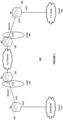
- Figure 1 illustrates an example of a network scenario 100 involving a first network denoted customer A (Cust A) 110 having an IP network address 8.8.8.0/24 and a second network denoted customer B (Cust-B) 120 having an IP network address 7.7.7.0/24.
- Figure 1 also shows four routers R1 101, R2 102, R3 103 and R4 104.
- Router R3 103 is shown connected to Cust-A 110 and router R4 104 is connected to Cust-B 120.
- the network between R1 101 and R2 102 may be the internet or any type of network.
- L-VRF 105 is assigned to physical interface e1/0 of router R1 101 and R-VRF 106 is assigned to physical interface e1/0 of router R2 102.
- the physical interfaces of the other routers are also depicted.
- a standard solution is to run dynamic routing and using MP-BPG (MultiProtocol-Boarder Gateway Protocol) to advertise the prefixes between the VRFs.
- MP-BPG MultiProtocol-Boarder Gateway Protocol
- Another option would be to use static routes to route traffic or data packets destined to prefix 7.7.7.0/24 from L-VRF 105 towards R-VRF 106 using e.g. the following command line on router R1 101: R1# ip route vrf 1-vrf 7.7.7.0/24 40.0.0.1
- routing traffic statically from a source VRF to a destination VRF requires that the destination VRF be placed on a physical interface, which is thus a limitation.
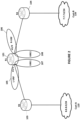
- FIG. 2 illustrates another example of a network scenario involving additional VRF(s).
- the two VRFs L-VRF 105 and R-VRF 106 are both placed on different physical interfaces of router R1 101 e1/1 respectively e1/0.
- FIG. 2 depicts two additional VRFs which are here considered to be inside or within router R1 101. These VRFs are denoted VRF1 107 and VRF2 108.
- a connection between Cust-A 110 and Cust-B 120 could be: 8.8.8.0/24 ⁇ -> L-VRF ⁇ -> VRF1 ⁇ -> VRF2 ⁇ -> R-VRF ⁇ -> 7.7.7.0/24
- FIG. 3 illustrates such a scenario involving a switch device 109.
- VRF1 107 is placed on physical interface e1/2 of router R1 101 and VRF2 108 is placed on physical interface e1/3 of R1 101.
- this design involving the external switch device 109 it is possible to configure or create a static route between VRF1 107 and VRF2 108 because the source and destination VRF are placed on physical interfaces so traffic can be routed.
- network Cust-A 110 and network Cust-B 120 are not directly connected to the VRFs. Instead they are behind the VRFs with one or more hop distances. If Cust-A 110 and Cust-B 120 were directly connected to the VRFs through physical interfaces, a standard solution to connect them is by using the BGP MPLS (MultiProtocol Label Switching) Route leaking technique.
- BGP MPLS MultiProtocol Label Switching
- routing process increases and introduces latency because of having back and forth traffic between the router and the external switch.
- service stability level may be affected and is not scalable.
- required redundancy increases with the number of extra hardware needed.
- This prior art document provides instruction on how to validate Inter VRF communication using route leaking and static routes on ArubaOS-CX.
- the above prior art document requires the use of two hardware devices for the solution to work.
- Prior art document WO 2019/129236 A1 discloses a tunnel-based data transmission method and device.
- VRFs and loopback interface are used in addition to encapsulating a packet in a tunnel and configuring an outlet of the tunnel as a loopback por, and looping back the packet encapsulated in the tunnel at the loopback port.
- the encapsulated packets are forwarded in the tunnel by means of a plurality of forwarding ports corresponding to the plurality of next hop IP addresses. Encapsulating increases the overhead and induces delays.
- a method performed by a router device comprising: configuring a first loopback interface and assigning an internal Virtual Route Forwarder (VRF1) to the first loopback interface; configuring a second loopback interface and assigning an internal Virtual Route Forwarder (VRF2) to the second loopback interface; said internal VRF2 being different from the internal VRF1; creating or configuring at least a first Generic Routing Encapsulation (GRE) tunnel and a second GRE tunnel to be used by interfaces within the router device; assigning the first GRE tunnel to the internal VRF1 and assigning the second GRE tunnel to the internal VRF2.
- VRF1 Virtual Route Forwarder
- VRF2 Virtual Route Forwarder
- GRE Generic Routing Encapsulation
- For the first GRE tunnel assigning the first loopback interface as a source point of the first GRE tunnel and assigning the second loopback interface as a destination point of the first GRE tunnel.
- assigning the second loopback interface assigning the second loopback interface as a source point of the second GRE tunnel and assigning the first loopback interface as a destination point of the second GRE tunnel.
- the method further comprises: configuring a source Internet Protocol (IP) address and a destination IP address of both the first GRE tunnel and the second GRE tunnel to use the same routing table from a routing table of VRF1 or from a routing table of VRF2; creating or configuring a first static route on VRF1 to route data packets destined to a network behind VRF2 by defining the IP address of the second GRE tunnel as the destination IP address in the first static route; and creating or configuring a second static route on VRF2 to route data packets destined to a network behind VRF1 by defining the IP address of the first GRE tunnel as the destination IP address in the second static route.
- IP Internet Protocol
- a router device comprising a processor and a memory, said memory containing instructions executable by said processor whereby the router device is operative to: configure a first loopback interface and assign an internal Virtual Route Forwarder (VRF1) to the first loopback interface; configure a second loopback interface and assign an internal Virtual Route Forwarder (VRF2) to the second loopback interface; said internal VRF2 being different from the internal VRF1; create or configure at least a first Generic Routing Encapsulation (GRE) tunnel and a second GRE tunnel to be used by interfaces within the router device; assign the first GRE tunnel to the internal VRF1 and assigning the second GRE tunnel to the internal VRF2.
- VRF1 Virtual Route Forwarder
- VRF2 Virtual Route Forwarder
- GRE Generic Routing Encapsulation
- the router device is further operative to assign the first GRE tunnel to the internal VRF1 and assigning the second GRE tunnel to the internal VRF2; configure a source IP address and a destination IP address of both the first GRE tunnel and the second GRE tunnel to use the same routing table from a routing table of VRF1 or from a routing table of VRF2; create or configure a first static route on VRF1 to route data packets destined to a network behind VRF2 by defining the Internet Protocol (IP) address of the second GRE tunnel as the destination IP address in the first static route; and create or configure a second static route on VRF2 to route data packets to a network behind VRF1 by
- IP Internet Protocol
- An advantage with embodiments herein is to achieve routing between internal VRFs by configuring static routes between the internal VRFs within a router device for advertising non-directly connected prefixes.
- Another advantage with embodiments herein is that there no need to have extra hardware equipment or resource to achieve the routing between the internal VRFs or through the VRFs.
- a further advantage with embodiments herein is that running the router internally is much faster instead of back and forth traffic between a router device and e.g. an external switch device.
- FIG. 4 there are illustrated two network scenarios wherein embodiments herein may be employed. As shown in Figure 4 , there is no need for an extra switch device compared to the scenario of Figure 3 .
- loopback1 or LB1 107A
- Loopback2 or LB2
- LB1 107A is assigned to VRF1 107 and LB2 108A is assigned to VRF2 108.
- FIG. 5 An example of commands used to create or configure, in Router R1 101, the loopback interfaces (or loopback adapters) and assign each one of them to a VRF is shown below with reference to Figure 5 which shows router R1 101 connected to two networks, Network A (e.g. Cust-A) and Network B (e.g. Cust-B) via e.g. internet or other networks by means physical interfaces 1 and 2: 1) Creating/configuring Loopback 1 (or LB1) 107A and assigning to internal VRF1 107 (or first VRF) and creating or configuring Loopback 2 (or LB2) 108A and assigning to internal VRF2 108 (or second VRF) in Router R1 101.
- Network A e.g. Cust-A
- Network B e.g. Cust-B
- each command line is also provided: R1# interface Loopback1 ⁇ create loopback interface (Loopbackl) ip vrf forwarding VRF1 ⁇ assign the loopback to VRF1 ip address 20.20.20.1/24 ⁇ assign IP address to Loopback1 interface Loopback2 ⁇ create loopback interface (Loopback2) ip vrf forwarding VRF2 ⁇ assign the loopback to VRF2 ip address 30.30.30.1/24 ⁇ assign IP address to Loopback2
- Loopback1 107A and Loopback2 108A are in different subnets i.e.:
- IP address or addresses 20.20.20.1/24 and 30.30.30.1/24 or the subnets 20.20.20.0/24 and 30.30.30.0/24 are only examples.
- At least a first tunnel and a second tunnel are configured or created to be used by interfaces within the router device R1.
- the tunnels may be Generic Routing Encapsulation (GRE) tunnels.
- GRE Generic Routing Encapsulation
- the first GRE tunnel (or tunnel interface) 107B is assigned to VRF1 107 and the second GRE tunnel (or tunnel interface) 108B is assigned to VRF2 108.
- An example of commands used for the creation/configuration of the GRE tunnels and the assignment of the GRE tunnels in router device R1 101 are shown below: 2) Creating/configuring GRE tunnels (denoted GRE Tunnel1 interface and GRE Tunnel2 interface) and assigning to VRF1 107 and VRF2 108 respectively in Router R1 101.
- the tunnel interface IP address on each tunnel is defined or configured. These tunnel interface IP addresses or endpoint IP addresses are automatically placed to assigned VRF to the respective tunnel.
- the IP addresses of the first GRE tunnel 107B and the second GRE tunnel 108B are different but they are in the same subnet 10.10.10.0/24.
- IP address 10.10.10.1/24 is only an example of an IP address for the tunnel interface IP address for Tunnel1 107B and 10.1010.2/24 is also only an example for the tunnel interface IP address for Tunnel2 108B.
- the first GRE tunnel (Tunnel1) 107B we assign the first loopback interface (Loopback1 or LB1) 107A as a source point of Tunnel1 and we assign the second loopback interface (Loopback2 or LB2) 108A as a destination point of Tunnel1.
- 20.20.20.1 is the IP address of Loopback1 and 30.30.30.1 is the IP address of Loopback2.
- Command line "tunnel source Loopback1" means that we define or assign Loopback1 as a source point of the first GRE tunnel and command line "tunnel destination 30.30.30.1” means that we define or assign the second loopback interface having address 30.30.30.1 as a destination point of the first GRE tunnel, Tunnel1.
- command line "tunnel source Loopback2" means that we define or assign Loopback2 as a source point of the second GRE tunnel and command line “tunnel destination 20.20.20.1” means that we define or assign the first loopback interface having address 20.20.20.1 as a destination point of the second GRE tunnel, Tunnel2.
- VRF technology allows multiple instances of a routing table to coexist in the same router simultaneously. This means that each VRF has its own routing table. Hence, VRF1 has one routing table and VRF2 has one routing table being different than the routing table of VRF1.
- the source IP address and the destination IP address of both the first GRE tunnel 107B and the second GRE tunnel 108B are configured to use the same routing table from a routing table of VRF1 107 or from a routing table of VRF2 108.
- the source IP address of the first GRE tunnel is Loopback1 IP address and the destination IP address of the first GRE tunnel is 30.30.30.1.
- the source IP address of the second GRE tunnel is Loopback2 IP address and the destination IP address of the second GRE tunnel is 20.20.20.1.
- These source and IP addresses of the first respectively the second GRE tunnels are configured to use the same routing table from a routing table of VRF1 or from a routing table of VRF2 as described above.
- a first static route may be configured on VRF1 107 to route packets destined to a network behind VRF2 108 by defining the IP address of the second GRE tunnel 108B as the destination.
- the network behind VRF2 108 is Network B (or a first network).
- the second static route may be configured on VRF2 108 to route traffic destined to a network behind VRF1 107 by defining the IP address of the first GRE tunnel 107B as the destination.
- the network behind VRF1 107 is Network A (or a second network).
- IP addresses 10.10.10.1 and 10.10.10.2 for the first GRE tunnel and for the second GRE tunnel respectively are in the same subnet which is 10.10.10.0/24.
- Network-B may have IP address 7.7.7.0/24 as IP address of Cust-B and Network-A may have IP address 8.8.8.0/24 as IP address of Cust-A. Note however that these addresses are only examples.
- Another advantage with the solution presented above is that it is scalable and additional latency is avoided because running the router internally is much faster instead of back and forth traffic between a router device and e.g. an external switch device.
- the main steps comprise:
- the network behind VRF2 may be a first network such as Network B shown in Figure 5 ; and the network behind VRF1 may be a second network such as Network A shown in Figure 5 .
- the method further comprises assigning to the source point of the first GRE tunnel, the first loopback interface as a source IP address and assigning to the destination point of the first GRE tunnel, the second loopback interface as a destination IP address.
- the method further comprises assigning to the source point of the second GRE tunnel, the second loopback interface as a source IP address and assigning to the destination point of the second GRE tunnel, the first loopback interface as a destination IP address.
- Assigning the first GRE tunnel to the internal VRF1 and assigning the second GRE tunnel to the internal VRF2 further comprises assigning an IP address for the first GRE tunnel and assigning an IP address for the second GRE tunnel, and wherein the assigned IP address for the first GRE tunnel and the assigned IP address for the second GRE tunnel are in a same subnet, as previously described.
- the IP address of the first GRE tunnel and the IP address of the second GRE tunnel are in a same subnet. But the IP address of the first loopback and the IP address of the second loopback are in different subnets.
- IP addresses of the first loopback interface and IP addresses of the second loopback interface are in different subnets, and the subnet used for the first and second GRE tunnels is different from each of the subnets of the first loopback interface and the subnet of the second loopback interface.
- a router device 700 is provided as shown in a simplified block diagram of Figure 7 . It should be noted that the router device 700 is configured to perform functions or operations of router device R1 101 previously described and shown with reference to Figure 5 . Therefore, in Figure 7 , both reference numbers 700 and 101 are used for the router device. As shown, the router device 700 comprises a processing circuit or a processing module or a processor 710; a memory module 720; a receiver circuit or receiver module 740; a transmitter circuit or transmitted module 750; and a transceiver circuit or transceiver module 730 which may include the transmitter circuit 750 and the receiver circuit 740.
- the router may be a wireless router device or fix router device that can be connected through cables to hosts and to other network devices.
- the router device 700 may support any radio access technology including 2G, 3G, 4G, 5G, Wifi, Wimax or a combination thereof.
- the processing module/circuit 710 includes a processor, microprocessor, an application specific integrated circuit (ASIC), field programmable gate array (FPGA), or the like, and may be referred to as the "processor 710."
- the processor 710 controls the operation of the router 400 and its components.
- Memory (circuit or module) 720 includes a random-access memory (RAM), a read only memory (ROM), and/or another type of memory to store data and instructions that may be used by processor 710.
- RAM random-access memory
- ROM read only memory
- the router device 700 in one or more embodiments includes fixed or programmed circuitry that is configured to carry out the operations in any of the embodiments disclosed herein.
- the processor 710 is configured to execute computer program instructions from a computer program stored in a non-transitory computer-readable medium that is in or is accessible to the processing circuitry.
- non-transitory does not necessarily mean permanent or unchanging storage, and may include storage in working or volatile memory, but the term does connote storage of at least some persistence.
- the execution of the program instructions stored in the memory specially adapts or configures the processor 710 to carry out the operations of the router device 700 disclosed herein.
- the figure also shows a simplified example of a physical interface module 760 which comprises at least two physical interfaces (not shown) such as the ones shown in Figure 5 . It will be appreciated that the router device 700 may comprise additional components not shown in Figure 7 .
- the router device 700 101, by means of processor 710, is operative to: configure a first loopback interface and assign an internal virtual route forwarder (VRF1) to the first loopback interface; configure a second loopback interface and assign an internal virtual route forwarder (VRF2) to the second loopback interface; said internal VRF2 being different from the internal VRF1; create or configure at least a first GRE tunnel and a second GRE tunnel to be used by interfaces within the router device; assign the first GRE tunnel to the internal VRF1 and assigning the second GRE tunnel to the internal VRF2. For the first GRE tunnel, assign the first loopback interface as a source point of the first GRE tunnel and assign the second loopback interface as a destination point of the first GRE tunnel.
- VRF1 virtual route forwarder
- VRF2 internal virtual route forwarder
- the router device is further operative to assign the first GRE tunnel to the internal VRF1 and assigning the second GRE tunnel to the internal VRF2; configure a source IP address and a destination IP address of both the first GRE tunnel and the second GRE tunnel to use the same routing table from a routing table of VRF1 or from a routing table of VRF2; create or configure a first static route on VRF1 to route data packets destined to a network behind VRF2 by defining the IP address of the second GRE tunnel as the destination; and create or configure a second static route on VRF2 to route data packets to a network behind VRF1 by defining the IP address of the first GRE tunnel as the destination.
- the network behind VRF2 may be a first network (e.g. Network-B) and the VRF behind VRF1 may be a second network
- the router device 700, 101 is operative to assign to the source point of the first GRE tunnel the first loopback interface as a source IP address and assign to the destination point of the first GRE tunnel the second loopback interface as a destination IP address.
- the router device is further operative to configure to the source point of the second GRE tunnel, the second loopback interface as a source IP address and assign to the destination point of the second GRE tunnel, the first loopback interface as a destination IP address.
- the router device 700 is operative to assign an IP address for the first GRE tunnel and assign an IP address for the second GRE tunnel, and wherein the assigned IP address for the first GRE tunnel and the assigned IP address for the second GRE tunnel are in a same subnet.
- IP addresses for the first loopback interface and IP addresses for the second loopback interface are in different subnets, and wherein the subnet used for the first and second GRE tunnels is different from each of the subnets of the first loopback and the subnet of the second loopback.
- VRF1 and VRF2 are both internal VRFs of the router device 700, 101.
- a computer program comprising instructions which when executed on at least one processor 710 of the router device 700 according to embodiments herein, cause the at least one processor 710 to carry out the method previously described.
- a carrier containing the computer program is provided, wherein the carrier is one of a computer readable storage medium; an electronic signal, optical signal or a radio signal.
Landscapes
- Engineering & Computer Science (AREA)
- Computer Networks & Wireless Communication (AREA)
- Signal Processing (AREA)
- Data Exchanges In Wide-Area Networks (AREA)
Claims (11)
- Verfahren, durchgeführt durch eine Router-Einrichtung (700, 101), wobei das Verfahren Folgendes umfasst:- Konfigurieren (601) einer ersten Loopback-Schnittstelle und Zuweisen eines internen Virtual Route Forwarder, VRF1, zu der ersten Loopback-Schnittstelle;- Konfigurieren (602) einer zweiten Loopback-Schnittstelle und Zuweisen eines internen Virtual Route Forwarder, VRF2, zu der zweiten Loopback-Schnittstelle; wobei sich der interne VRF2 von dem internen VRF1 unterscheidet;- Erstellen oder Konfigurieren (603) mindestens eines ersten Generic-Routing-Encapsulation-, GRE-, Tunnels und eines zweiten GRE-Tunnels zur Verwendung durch Schnittstellen innerhalb der Router-Einrichtung;- Zuweisen (604) des ersten GRE-Tunnels zu dem internen VRF1 und Zuweisen des zweiten GRE-Tunnels zu dem internen VRF2;- für den ersten GRE-Tunnel Zuweisen (605) der ersten Loopback-Schnittstelle als Quellpunkt des ersten GRE-Tunnels und Zuweisen der zweiten Loopback-Schnittstelle als Zielpunkt des ersten GRE-Tunnels;- für den zweiten GRE-Tunnel Zuweisen (606) der zweiten Loopback-Schnittstelle als Quellpunkt des zweiten GRE-Tunnels und Zuweisen der ersten Loopback-Schnittstelle als Zielpunkt des zweiten GRE-Tunnels;- Konfigurieren (607) einer Quell-Internetprotokoll-, IP-, Adresse und einer Ziel-IP-Adresse sowohl des ersten GRE-Tunnels als auch des zweiten GRE-Tunnels zum Verwenden derselben Routing-Tabelle aus einer Routing-Tabelle von VRF1 oder einer Routing-Tabelle von VRF2;- Erstellen oder Konfigurieren (608) einer ersten statischen Route an VRF1, um Datenpakete weiterzuleiten, die für ein Netzwerk hinter VRF2 bestimmt sind, indem die IP-Adresse des zweiten GRE-Tunnels als Ziel-IP-Adresse in der ersten statischen Route definiert wird; und- Erstellen oder Konfigurieren (609) einer zweiten statischen Route an VRF2, um Datenpakete weiterzuleiten, die für ein Netzwerk hinter VRF1 bestimmt sind, indem die IP-Adresse des ersten GRE-Tunnels als Ziel-IP-Adresse in der zweiten statischen Route definiert wird.
- Verfahren nach Anspruch 1, umfassend Zuweisen der ersten Loopback-Schnittstelle als eine Quell-IP-Adresse zu dem Quellpunkt des ersten GRE-Tunnels und Zuweisen der IP-Adresse der zweiten Loopback-Schnittstelle als eine Ziel-IP-Adresse zu dem Zielpunkt des ersten GRE-Tunnels.
- Verfahren nach Anspruch 1 oder 2, umfassend Konfigurieren der ersten Loopback-Schnittstelle als eine Quell-IP-Adresse an den Quellpunkt des zweiten GRE-Tunnels und Zuweisen der IP-Adresse der ersten Loopback-Schnittstelle als eine Ziel-IP-Adresse zu dem Zielpunkt des zweiten GRE-Tunnels.
- Verfahren nach einem der Ansprüche 1-4, wobei das Zuweisen (604) des ersten GRE-Tunnels zu dem internen VRF1 und das Zuweisen des zweiten GRE-Tunnels zu dem internen VRF2 ferner Zuweisen einer IP-Adresse für den ersten GRE-Tunnel und Zuweisen einer IP-Adresse für den zweiten GRE-Tunnel umfasst, und wobei die zugewiesene IP-Adresse für den ersten GRE-Tunnel und die zugewiesene IP-Adresse für den zweiten GRE-Tunnel in einem selben Teilnetzwerk liegen.
- Verfahren nach einem der Ansprüche 1-5, wobei IP-Adressen der ersten Loopback-Schnittstelle und IP-Adressen der zweiten Loopback-Schnittstelle in unterschiedlichen Teilnetzwerken liegen und wobei sich das für den ersten und zweiten GRE-Tunnel verwendete Teilnetzwerk jeweils von den Teilnetzwerken der ersten Loopback-Schnittstelle und dem Teilnetzwerk der zweiten Loopback-Schnittstelle unterscheiden.
- Router-Einrichtung (700, 101), umfassend einen Prozessor (710) und einen Speicher (720), wobei der Speicher (720) Anweisungen enthält, die durch den Prozessor (710) ausführbar sind, wodurch die Router-Einrichtung (700, 101) betriebsfähig ist zum:- Konfigurieren einer ersten Loopback-Schnittstelle (107A) und Zuweisen eines internen Virtual Route Forwarder, VRF1, (107) zu der ersten Loopback-Schnittstelle (107A);- Konfigurieren einer zweiten Loopback-Schnittstelle (108A) und Zuweisen eines internen Virtual Route Forwarder, VRF2, (108) zu der zweiten Loopback-Schnittstelle (108A); wobei sich der interne VRF2 (108) von dem internen VRF1 (107) unterscheidet;- Erstellen oder Konfigurieren mindestens eines ersten Generic-Routing-Encapsulation-, GRE-, Tunnels (107B) und eines zweiten GRE-Tunnels (108B) zur Verwendung durch Schnittstellen innerhalb der Router-Einrichtung (700, 101);- Zuweisen des ersten GRE-Tunnels (107B) zu dem internen VRF1 (107) und Zuweisen des zweiten GRE-Tunnels (108B) zu dem internen VRF2 (108);- für den ersten GRE-Tunnel (107B) Zuweisen der ersten Loopback-Schnittstelle (107A) als Quellpunkt des ersten GRE-Tunnels (107B) und Zuweisen der zweiten Loopback-Schnittstelle (108A) als Zielpunkt des ersten GRE-Tunnels (107B);- für den zweiten GRE-Tunnel Zuweisen (108B) der zweiten Loopback-Schnittstelle (108A) als Quellpunkt des zweiten GRE-Tunnels (108B) und Zuweisen der ersten Loopback-Schnittstelle (107A) als Zielpunkt des zweiten GRE-Tunnels (108B);- Konfigurieren einer Quell-Internetprotokoll-, IP-, Adresse und einer Ziel-IP-Adresse sowohl des ersten GRE-Tunnels (107B) als auch des zweiten GRE-Tunnels (108B) zum Verwenden derselben Routing-Tabelle aus einer Routing-Tabelle von VRF1 (107) oder einer Routing-Tabelle von VRF2 (108);- Erstellen oder Konfigurieren einer ersten statischen Route an VRF1 (107), um Datenpakete weiterzuleiten, die für ein Netzwerk hinter VRF2 (108) bestimmt sind, indem die IP-Adresse des zweiten GRE-Tunnels (108B) als Ziel-IP-Adresse in der ersten statischen Route definiert wird; und- Erstellen oder Konfigurieren einer zweiten statischen Route an VRF2 (108), um Datenpakete weiterzuleiten, die für ein Netzwerk hinter VRF1 (107) bestimmt sind, indem die IP-Adresse des ersten GRE-Tunnels (107B) als Ziel-IP-Adresse in der zweiten statischen Route definiert wird.
- Router-Einrichtung (700, 101) nach Anspruch 6, die betriebsfähig ist zum Zuweisen der ersten Loopback-Schnittstelle (107A) als eine Quell-IP-Adresse an den Quellpunkt des ersten GRE-Tunnels (107B) und Zuweisen der IP-Adresse der zweiten Loopback-Schnittstelle (108A) als eine Ziel-IP-Adresse zu dem Zielpunkt des ersten GRE-Tunnels (107B).
- Router-Einrichtung (700, 101) nach Anspruch 6 oder Anspruch 7, die betriebsfähig ist zum Zuweisen der zweiten Loopback-Schnittstelle (108A) als eine Quell-IP-Adresse an den Quellpunkt des zweiten GRE-Tunnels (108B) und Zuweisen der IP-Adresse der ersten Loopback-Schnittstelle (107A) als eine Ziel-IP-Adresse zu dem Zielpunkt des zweiten GRE-Tunnels (108B).
- Router-Einrichtung (700, 101) nach einem der Ansprüche 6-8, die betriebsfähig ist, um eine IP-Adresse für den ersten GRE-Tunnel zuzuweisen und eine IP-Adresse für den zweiten GRE-Tunnel zuzuweisen, und wobei die zugewiesene IP-Adresse für den ersten GRE-Tunnel und die zugewiesene IP-Adresse für den zweiten GRE-Tunnel in einem selben Teilnetzwerk liegen.
- Router-Einrichtung nach einem der Ansprüche 6-9, wobei IP-Adressen der ersten Loopback-Schnittstelle (107A) und IP-Adressen für die zweite Loopback-Schnittstelle (108A) in unterschiedlichen Teilnetzwerken liegen und wobei sich das für den ersten und zweiten GRE-Tunnel verwendete Teilnetzwerk jeweils von den Teilnetzwerken des ersten Loopback und dem Teilnetzwerk des zweiten Loopback unterscheiden.
- Router-Einrichtung nach einem der Ansprüche 6-10, wobei VRF1 (107) und VRF2 (108) beide interne VRFs der Router-Einrichtung (700, 101) sind.
Applications Claiming Priority (1)
| Application Number | Priority Date | Filing Date | Title |
|---|---|---|---|
| SE1951128A SE544376C2 (en) | 2019-10-03 | 2019-10-03 | A method and an apparatus for configuring static routes through internal virtual route forwarders |
Publications (2)
| Publication Number | Publication Date |
|---|---|
| EP3800841A1 EP3800841A1 (de) | 2021-04-07 |
| EP3800841B1 true EP3800841B1 (de) | 2023-08-02 |
Family
ID=72615615
Family Applications (1)
| Application Number | Title | Priority Date | Filing Date |
|---|---|---|---|
| EP20197511.7A Active EP3800841B1 (de) | 2019-10-03 | 2020-09-22 | Verfahren und vorrichtung zum routen von datenpaketen in einem netzwerk |
Country Status (5)
| Country | Link |
|---|---|
| US (1) | US11463359B2 (de) |
| EP (1) | EP3800841B1 (de) |
| DK (1) | DK3800841T3 (de) |
| FI (1) | FI3800841T3 (de) |
| SE (1) | SE544376C2 (de) |
Families Citing this family (4)
| Publication number | Priority date | Publication date | Assignee | Title |
|---|---|---|---|---|
| EP4154492B8 (de) * | 2020-05-21 | 2024-05-22 | BAE SYSTEMS plc | Sicheres kommunikationssystem |
| US12388741B2 (en) * | 2022-02-01 | 2025-08-12 | Amazon Technologies, Inc. | Routing for static border gateway protocol |
| EP4701164A3 (de) * | 2022-04-18 | 2026-04-29 | Cisco Technology, Inc. | Systeme und verfahren zur bereitstellung von sd-wan-gewebekonnektivität über ein automatisches ipv4 über ipv6-tunnel |
| CN116506344A (zh) * | 2023-05-18 | 2023-07-28 | 浪潮思科网络科技有限公司 | 一种路由泄露优化方法、设备及介质 |
Family Cites Families (6)
| Publication number | Priority date | Publication date | Assignee | Title |
|---|---|---|---|---|
| SE0200640D0 (sv) * | 2002-02-28 | 2002-02-28 | Ericsson Telefon Ab L M | Arrangement and method for routing in virtual private network |
| WO2009086931A1 (en) * | 2008-01-09 | 2009-07-16 | Telefonaktiebolaget Lm Ericsson (Publ) | Setting up a virtual private network |
| US20100329252A1 (en) * | 2009-06-26 | 2010-12-30 | Nortel Networks Limited | Method and Apparatus for Enabling Multicast Route Leaking Between VRFs in Different VPNs |
| US9621460B2 (en) * | 2013-01-14 | 2017-04-11 | Versa Networks, Inc. | Connecting multiple customer sites over a wide area network using an overlay network |
| US9825777B2 (en) * | 2015-06-23 | 2017-11-21 | Cisco Technology, Inc. | Virtual private network forwarding and nexthop to transport mapping scheme |
| CN109995654B (zh) * | 2017-12-29 | 2022-05-20 | 中兴通讯股份有限公司 | 一种基于隧道传输数据的方法及装置 |
-
2019
- 2019-10-03 SE SE1951128A patent/SE544376C2/en unknown
-
2020
- 2020-09-22 DK DK20197511.7T patent/DK3800841T3/da active
- 2020-09-22 EP EP20197511.7A patent/EP3800841B1/de active Active
- 2020-09-22 FI FIEP20197511.7T patent/FI3800841T3/fi active
- 2020-09-29 US US17/036,773 patent/US11463359B2/en active Active
Also Published As
| Publication number | Publication date |
|---|---|
| US20210105209A1 (en) | 2021-04-08 |
| SE1951128A1 (en) | 2021-04-04 |
| SE544376C2 (en) | 2022-04-26 |
| US11463359B2 (en) | 2022-10-04 |
| EP3800841A1 (de) | 2021-04-07 |
| FI3800841T3 (fi) | 2023-10-31 |
| DK3800841T3 (da) | 2023-10-23 |
Similar Documents
| Publication | Publication Date | Title |
|---|---|---|
| EP3800841B1 (de) | Verfahren und vorrichtung zum routen von datenpaketen in einem netzwerk | |
| US11895006B2 (en) | Communication method, device, and system | |
| CN112584393B (zh) | 一种基站配置方法、装置、设备及介质 | |
| CN108574639B (zh) | Evpn报文处理方法、设备及系统 | |
| EP2926507B1 (de) | Verfahren und router für konnektivitätsaufbau zwischen anbieter-edge-routern | |
| CN111988266B (zh) | 一种处理报文的方法 | |
| CN104113459A (zh) | 一种evi网络中虚拟机平滑迁移方法和装置 | |
| EP3301868B1 (de) | Symmetrische intersubnet-verkehrslastverteilung in multihoming-netzwerken | |
| KR102936155B1 (ko) | 할당된 컨텍스트에 기초하는 네트워크 서비스 액세스 및 데이터 라우팅 | |
| CN106789657B (zh) | 一种报文转发方法及装置 | |
| US11895021B2 (en) | Message sending and receiving method, apparatus, and system | |
| EP4027592B1 (de) | Paketverarbeitungsverfahren und -vorrichtung | |
| JP7696434B2 (ja) | パケット転送方法および装置、ならびにネットワークシステム | |
| US10862708B2 (en) | Interoperability between separate and collapsed service-layer and transport-layer tunnels | |
| CN107733800A (zh) | 一种sdn网络报文传输方法及其装置 | |
| EP3585016B1 (de) | Weiterleitung von multicast-datenpaketen mit einer bitindex-expliziten replikation (bier) für bier-unfähige netzwerkvorrichtungen | |
| US10715431B2 (en) | Methods and apparatuses for routing data packets in a network topology | |
| US10812370B2 (en) | Unified control plane over MPLS and internet interfaces through BGP | |
| EP4068700B1 (de) | Verfahren und vorrichtung zur verarbeitung von routinginformationen | |
| US12574324B2 (en) | Route advertisement method, packet forwarding method, device, and system | |
| EP4459946A1 (de) | Routenwerbungsverfahren, netzwerkvorrichtung und system | |
| EP4485883A1 (de) | Option für ein interautonomes system (inter-as) | |
| CN119728538A (zh) | 一种路由通告、报文传输方法及装置 | |
| EP3148132B1 (de) | Verfahren zum senden und/oder empfangen von netzwerkschichterreichbarkeitsinformationen durch einen netzwerkknoten eines telekommunikationsnetzwerks, telekommunikationsnetzwerk, netzwerkknoten, programm und computerprogrammprodukt | |
| CN120017581A (zh) | 路由发布方法、报文传输方法及通信装置、通信系统 |
Legal Events
| Date | Code | Title | Description |
|---|---|---|---|
| PUAI | Public reference made under article 153(3) epc to a published international application that has entered the european phase |
Free format text: ORIGINAL CODE: 0009012 |
|
| STAA | Information on the status of an ep patent application or granted ep patent |
Free format text: STATUS: THE APPLICATION HAS BEEN PUBLISHED |
|
| AK | Designated contracting states |
Kind code of ref document: A1 Designated state(s): AL AT BE BG CH CY CZ DE DK EE ES FI FR GB GR HR HU IE IS IT LI LT LU LV MC MK MT NL NO PL PT RO RS SE SI SK SM TR |
|
| AX | Request for extension of the european patent |
Extension state: BA ME |
|
| STAA | Information on the status of an ep patent application or granted ep patent |
Free format text: STATUS: REQUEST FOR EXAMINATION WAS MADE |
|
| 17P | Request for examination filed |
Effective date: 20210914 |
|
| RBV | Designated contracting states (corrected) |
Designated state(s): AL AT BE BG CH CY CZ DE DK EE ES FI FR GB GR HR HU IE IS IT LI LT LU LV MC MK MT NL NO PL PT RO RS SE SI SK SM TR |
|
| REG | Reference to a national code |
Ref country code: DE Free format text: PREVIOUS MAIN CLASS: H04L0012713000 Ref country code: DE Ref legal event code: R079 Ref document number: 602020014826 Country of ref document: DE Free format text: PREVIOUS MAIN CLASS: H04L0012713000 Ipc: H04L0045586000 |
|
| GRAP | Despatch of communication of intention to grant a patent |
Free format text: ORIGINAL CODE: EPIDOSNIGR1 |
|
| STAA | Information on the status of an ep patent application or granted ep patent |
Free format text: STATUS: GRANT OF PATENT IS INTENDED |
|
| RIC1 | Information provided on ipc code assigned before grant |
Ipc: H04L 12/46 20060101ALI20230216BHEP Ipc: H04L 45/74 20220101ALI20230216BHEP Ipc: H04L 45/586 20220101AFI20230216BHEP |
|
| INTG | Intention to grant announced |
Effective date: 20230316 |
|
| GRAS | Grant fee paid |
Free format text: ORIGINAL CODE: EPIDOSNIGR3 |
|
| GRAA | (expected) grant |
Free format text: ORIGINAL CODE: 0009210 |
|
| STAA | Information on the status of an ep patent application or granted ep patent |
Free format text: STATUS: THE PATENT HAS BEEN GRANTED |
|
| P01 | Opt-out of the competence of the unified patent court (upc) registered |
Effective date: 20230529 |
|
| P01 | Opt-out of the competence of the unified patent court (upc) registered |
Effective date: 20230616 |
|
| AK | Designated contracting states |
Kind code of ref document: B1 Designated state(s): AL AT BE BG CH CY CZ DE DK EE ES FI FR GB GR HR HU IE IS IT LI LT LU LV MC MK MT NL NO PL PT RO RS SE SI SK SM TR |
|
| REG | Reference to a national code |
Ref country code: GB Ref legal event code: FG4D |
|
| REG | Reference to a national code |
Ref country code: CH Ref legal event code: EP |
|
| REG | Reference to a national code |
Ref country code: DE Ref legal event code: R096 Ref document number: 602020014826 Country of ref document: DE |
|
| REG | Reference to a national code |
Ref country code: IE Ref legal event code: FG4D |
|
| REG | Reference to a national code |
Ref country code: NL Ref legal event code: FP |
|
| REG | Reference to a national code |
Ref country code: DK Ref legal event code: T3 Effective date: 20231020 |
|
| REG | Reference to a national code |
Ref country code: NO Ref legal event code: T2 Effective date: 20230802 |
|
| REG | Reference to a national code |
Ref country code: FI Ref legal event code: FGE |
|
| REG | Reference to a national code |
Ref country code: LT Ref legal event code: MG9D |
|
| REG | Reference to a national code |
Ref country code: AT Ref legal event code: MK05 Ref document number: 1596111 Country of ref document: AT Kind code of ref document: T Effective date: 20230802 |
|
| PG25 | Lapsed in a contracting state [announced via postgrant information from national office to epo] |
Ref country code: GR Free format text: LAPSE BECAUSE OF FAILURE TO SUBMIT A TRANSLATION OF THE DESCRIPTION OR TO PAY THE FEE WITHIN THE PRESCRIBED TIME-LIMIT Effective date: 20231103 |
|
| PG25 | Lapsed in a contracting state [announced via postgrant information from national office to epo] |
Ref country code: IS Free format text: LAPSE BECAUSE OF FAILURE TO SUBMIT A TRANSLATION OF THE DESCRIPTION OR TO PAY THE FEE WITHIN THE PRESCRIBED TIME-LIMIT Effective date: 20231202 |
|
| PG25 | Lapsed in a contracting state [announced via postgrant information from national office to epo] |
Ref country code: SE Free format text: LAPSE BECAUSE OF FAILURE TO SUBMIT A TRANSLATION OF THE DESCRIPTION OR TO PAY THE FEE WITHIN THE PRESCRIBED TIME-LIMIT Effective date: 20230802 Ref country code: RS Free format text: LAPSE BECAUSE OF FAILURE TO SUBMIT A TRANSLATION OF THE DESCRIPTION OR TO PAY THE FEE WITHIN THE PRESCRIBED TIME-LIMIT Effective date: 20230802 Ref country code: PT Free format text: LAPSE BECAUSE OF FAILURE TO SUBMIT A TRANSLATION OF THE DESCRIPTION OR TO PAY THE FEE WITHIN THE PRESCRIBED TIME-LIMIT Effective date: 20231204 Ref country code: LV Free format text: LAPSE BECAUSE OF FAILURE TO SUBMIT A TRANSLATION OF THE DESCRIPTION OR TO PAY THE FEE WITHIN THE PRESCRIBED TIME-LIMIT Effective date: 20230802 Ref country code: LT Free format text: LAPSE BECAUSE OF FAILURE TO SUBMIT A TRANSLATION OF THE DESCRIPTION OR TO PAY THE FEE WITHIN THE PRESCRIBED TIME-LIMIT Effective date: 20230802 Ref country code: IS Free format text: LAPSE BECAUSE OF FAILURE TO SUBMIT A TRANSLATION OF THE DESCRIPTION OR TO PAY THE FEE WITHIN THE PRESCRIBED TIME-LIMIT Effective date: 20231202 Ref country code: HR Free format text: LAPSE BECAUSE OF FAILURE TO SUBMIT A TRANSLATION OF THE DESCRIPTION OR TO PAY THE FEE WITHIN THE PRESCRIBED TIME-LIMIT Effective date: 20230802 Ref country code: GR Free format text: LAPSE BECAUSE OF FAILURE TO SUBMIT A TRANSLATION OF THE DESCRIPTION OR TO PAY THE FEE WITHIN THE PRESCRIBED TIME-LIMIT Effective date: 20231103 Ref country code: AT Free format text: LAPSE BECAUSE OF FAILURE TO SUBMIT A TRANSLATION OF THE DESCRIPTION OR TO PAY THE FEE WITHIN THE PRESCRIBED TIME-LIMIT Effective date: 20230802 |
|
| PG25 | Lapsed in a contracting state [announced via postgrant information from national office to epo] |
Ref country code: PL Free format text: LAPSE BECAUSE OF FAILURE TO SUBMIT A TRANSLATION OF THE DESCRIPTION OR TO PAY THE FEE WITHIN THE PRESCRIBED TIME-LIMIT Effective date: 20230802 |
|
| PG25 | Lapsed in a contracting state [announced via postgrant information from national office to epo] |
Ref country code: ES Free format text: LAPSE BECAUSE OF FAILURE TO SUBMIT A TRANSLATION OF THE DESCRIPTION OR TO PAY THE FEE WITHIN THE PRESCRIBED TIME-LIMIT Effective date: 20230802 |
|
| PG25 | Lapsed in a contracting state [announced via postgrant information from national office to epo] |
Ref country code: SM Free format text: LAPSE BECAUSE OF FAILURE TO SUBMIT A TRANSLATION OF THE DESCRIPTION OR TO PAY THE FEE WITHIN THE PRESCRIBED TIME-LIMIT Effective date: 20230802 Ref country code: RO Free format text: LAPSE BECAUSE OF FAILURE TO SUBMIT A TRANSLATION OF THE DESCRIPTION OR TO PAY THE FEE WITHIN THE PRESCRIBED TIME-LIMIT Effective date: 20230802 Ref country code: ES Free format text: LAPSE BECAUSE OF FAILURE TO SUBMIT A TRANSLATION OF THE DESCRIPTION OR TO PAY THE FEE WITHIN THE PRESCRIBED TIME-LIMIT Effective date: 20230802 Ref country code: EE Free format text: LAPSE BECAUSE OF FAILURE TO SUBMIT A TRANSLATION OF THE DESCRIPTION OR TO PAY THE FEE WITHIN THE PRESCRIBED TIME-LIMIT Effective date: 20230802 Ref country code: CZ Free format text: LAPSE BECAUSE OF FAILURE TO SUBMIT A TRANSLATION OF THE DESCRIPTION OR TO PAY THE FEE WITHIN THE PRESCRIBED TIME-LIMIT Effective date: 20230802 Ref country code: SK Free format text: LAPSE BECAUSE OF FAILURE TO SUBMIT A TRANSLATION OF THE DESCRIPTION OR TO PAY THE FEE WITHIN THE PRESCRIBED TIME-LIMIT Effective date: 20230802 |
|
| REG | Reference to a national code |
Ref country code: CH Ref legal event code: PL |
|
| REG | Reference to a national code |
Ref country code: DE Ref legal event code: R097 Ref document number: 602020014826 Country of ref document: DE |
|
| PG25 | Lapsed in a contracting state [announced via postgrant information from national office to epo] |
Ref country code: LU Free format text: LAPSE BECAUSE OF NON-PAYMENT OF DUE FEES Effective date: 20230922 |
|
| REG | Reference to a national code |
Ref country code: BE Ref legal event code: MM Effective date: 20230930 |
|
| PG25 | Lapsed in a contracting state [announced via postgrant information from national office to epo] |
Ref country code: LU Free format text: LAPSE BECAUSE OF NON-PAYMENT OF DUE FEES Effective date: 20230922 Ref country code: IT Free format text: LAPSE BECAUSE OF FAILURE TO SUBMIT A TRANSLATION OF THE DESCRIPTION OR TO PAY THE FEE WITHIN THE PRESCRIBED TIME-LIMIT Effective date: 20230802 Ref country code: MC Free format text: LAPSE BECAUSE OF FAILURE TO SUBMIT A TRANSLATION OF THE DESCRIPTION OR TO PAY THE FEE WITHIN THE PRESCRIBED TIME-LIMIT Effective date: 20230802 |
|
| PLBE | No opposition filed within time limit |
Free format text: ORIGINAL CODE: 0009261 |
|
| STAA | Information on the status of an ep patent application or granted ep patent |
Free format text: STATUS: NO OPPOSITION FILED WITHIN TIME LIMIT |
|
| REG | Reference to a national code |
Ref country code: IE Ref legal event code: MM4A |
|
| PG25 | Lapsed in a contracting state [announced via postgrant information from national office to epo] |
Ref country code: IE Free format text: LAPSE BECAUSE OF NON-PAYMENT OF DUE FEES Effective date: 20230922 |
|
| 26N | No opposition filed |
Effective date: 20240503 |
|
| PG25 | Lapsed in a contracting state [announced via postgrant information from national office to epo] |
Ref country code: CH Free format text: LAPSE BECAUSE OF NON-PAYMENT OF DUE FEES Effective date: 20230930 |
|
| PG25 | Lapsed in a contracting state [announced via postgrant information from national office to epo] |
Ref country code: IE Free format text: LAPSE BECAUSE OF NON-PAYMENT OF DUE FEES Effective date: 20230922 Ref country code: CH Free format text: LAPSE BECAUSE OF NON-PAYMENT OF DUE FEES Effective date: 20230930 Ref country code: SI Free format text: LAPSE BECAUSE OF FAILURE TO SUBMIT A TRANSLATION OF THE DESCRIPTION OR TO PAY THE FEE WITHIN THE PRESCRIBED TIME-LIMIT Effective date: 20230802 |
|
| PG25 | Lapsed in a contracting state [announced via postgrant information from national office to epo] |
Ref country code: BE Free format text: LAPSE BECAUSE OF NON-PAYMENT OF DUE FEES Effective date: 20230930 |
|
| PGFP | Annual fee paid to national office [announced via postgrant information from national office to epo] |
Ref country code: DK Payment date: 20240923 Year of fee payment: 5 |
|
| PG25 | Lapsed in a contracting state [announced via postgrant information from national office to epo] |
Ref country code: BG Free format text: LAPSE BECAUSE OF FAILURE TO SUBMIT A TRANSLATION OF THE DESCRIPTION OR TO PAY THE FEE WITHIN THE PRESCRIBED TIME-LIMIT Effective date: 20230802 |
|
| PG25 | Lapsed in a contracting state [announced via postgrant information from national office to epo] |
Ref country code: BG Free format text: LAPSE BECAUSE OF FAILURE TO SUBMIT A TRANSLATION OF THE DESCRIPTION OR TO PAY THE FEE WITHIN THE PRESCRIBED TIME-LIMIT Effective date: 20230802 |
|
| PG25 | Lapsed in a contracting state [announced via postgrant information from national office to epo] |
Ref country code: CY Free format text: LAPSE BECAUSE OF FAILURE TO SUBMIT A TRANSLATION OF THE DESCRIPTION OR TO PAY THE FEE WITHIN THE PRESCRIBED TIME-LIMIT; INVALID AB INITIO Effective date: 20200922 |
|
| PG25 | Lapsed in a contracting state [announced via postgrant information from national office to epo] |
Ref country code: HU Free format text: LAPSE BECAUSE OF FAILURE TO SUBMIT A TRANSLATION OF THE DESCRIPTION OR TO PAY THE FEE WITHIN THE PRESCRIBED TIME-LIMIT; INVALID AB INITIO Effective date: 20200922 |
|
| PGFP | Annual fee paid to national office [announced via postgrant information from national office to epo] |
Ref country code: FI Payment date: 20250926 Year of fee payment: 6 |
|
| PGFP | Annual fee paid to national office [announced via postgrant information from national office to epo] |
Ref country code: DE Payment date: 20250919 Year of fee payment: 6 |
|
| PGFP | Annual fee paid to national office [announced via postgrant information from national office to epo] |
Ref country code: NO Payment date: 20250923 Year of fee payment: 6 |
|
| PGFP | Annual fee paid to national office [announced via postgrant information from national office to epo] |
Ref country code: NL Payment date: 20250918 Year of fee payment: 6 |
|
| PGFP | Annual fee paid to national office [announced via postgrant information from national office to epo] |
Ref country code: GB Payment date: 20250919 Year of fee payment: 6 |
|
| PGFP | Annual fee paid to national office [announced via postgrant information from national office to epo] |
Ref country code: FR Payment date: 20250922 Year of fee payment: 6 |
|
| PG25 | Lapsed in a contracting state [announced via postgrant information from national office to epo] |
Ref country code: TR Free format text: LAPSE BECAUSE OF FAILURE TO SUBMIT A TRANSLATION OF THE DESCRIPTION OR TO PAY THE FEE WITHIN THE PRESCRIBED TIME-LIMIT Effective date: 20230802 |
|
| REG | Reference to a national code |
Ref country code: DK Ref legal event code: EBP Effective date: 20250930 |