EP3800655A1 - Quick disconnect switch - Google Patents
Quick disconnect switch Download PDFInfo
- Publication number
- EP3800655A1 EP3800655A1 EP19201212.8A EP19201212A EP3800655A1 EP 3800655 A1 EP3800655 A1 EP 3800655A1 EP 19201212 A EP19201212 A EP 19201212A EP 3800655 A1 EP3800655 A1 EP 3800655A1
- Authority
- EP
- European Patent Office
- Prior art keywords
- conductor
- expansion vessel
- disconnector
- rapid
- expansion
- Prior art date
- Legal status (The legal status is an assumption and is not a legal conclusion. Google has not performed a legal analysis and makes no representation as to the accuracy of the status listed.)
- Withdrawn
Links
Images


Classifications
-
- H—ELECTRICITY
- H01—ELECTRIC ELEMENTS
- H01H—ELECTRIC SWITCHES; RELAYS; SELECTORS; EMERGENCY PROTECTIVE DEVICES
- H01H39/00—Switching devices actuated by an explosion produced within the device and initiated by an electric current
-
- H—ELECTRICITY
- H01—ELECTRIC ELEMENTS
- H01H—ELECTRIC SWITCHES; RELAYS; SELECTORS; EMERGENCY PROTECTIVE DEVICES
- H01H39/00—Switching devices actuated by an explosion produced within the device and initiated by an electric current
- H01H39/006—Opening by severing a conductor
-
- F—MECHANICAL ENGINEERING; LIGHTING; HEATING; WEAPONS; BLASTING
- F42—AMMUNITION; BLASTING
- F42B—EXPLOSIVE CHARGES, e.g. FOR BLASTING, FIREWORKS, AMMUNITION
- F42B3/00—Blasting cartridges, i.e. case and explosive
- F42B3/006—Explosive bolts; Explosive actuators
-
- F—MECHANICAL ENGINEERING; LIGHTING; HEATING; WEAPONS; BLASTING
- F15—FLUID-PRESSURE ACTUATORS; HYDRAULICS OR PNEUMATICS IN GENERAL
- F15B—SYSTEMS ACTING BY MEANS OF FLUIDS IN GENERAL; FLUID-PRESSURE ACTUATORS, e.g. SERVOMOTORS; DETAILS OF FLUID-PRESSURE SYSTEMS, NOT OTHERWISE PROVIDED FOR
- F15B15/00—Fluid-actuated devices for displacing a member from one position to another; Gearing associated therewith
- F15B15/08—Characterised by the construction of the motor unit
- F15B15/10—Characterised by the construction of the motor unit the motor being of diaphragm type
-
- F—MECHANICAL ENGINEERING; LIGHTING; HEATING; WEAPONS; BLASTING
- F15—FLUID-PRESSURE ACTUATORS; HYDRAULICS OR PNEUMATICS IN GENERAL
- F15B—SYSTEMS ACTING BY MEANS OF FLUIDS IN GENERAL; FLUID-PRESSURE ACTUATORS, e.g. SERVOMOTORS; DETAILS OF FLUID-PRESSURE SYSTEMS, NOT OTHERWISE PROVIDED FOR
- F15B15/00—Fluid-actuated devices for displacing a member from one position to another; Gearing associated therewith
- F15B15/19—Pyrotechnical actuators
-
- H—ELECTRICITY
- H01—ELECTRIC ELEMENTS
- H01H—ELECTRIC SWITCHES; RELAYS; SELECTORS; EMERGENCY PROTECTIVE DEVICES
- H01H39/00—Switching devices actuated by an explosion produced within the device and initiated by an electric current
- H01H2039/008—Switching devices actuated by an explosion produced within the device and initiated by an electric current using the switch for a battery cutoff
Definitions
- the present invention relates to a quick disconnect switch, i. H. a switch with which you can disconnect an electrical circuit particularly quickly, even with high currents and high separation voltages.
- the switch is suitable for both DC and AC circuits.
- the switch usually uses a small amount of an explosive material for this purpose.
- Such switches are sometimes also referred to as pyrotechnic disconnection devices or also as electrical interruption switching elements.
- they can be used in the increasingly important field of e-mobility, in particular to protect electric drives, especially in electric cars, electric trucks or electric buses. If an appropriately powered vehicle has an accident, it is important and necessary to quickly disconnect the power source from the vehicle wiring.
- the corresponding questions also arise when propelling ships with electric motors or, in the meantime, when propelling aircraft with electric motors, but also when it comes to corresponding tasks in control cabinets in general.
- circuit breakers use the action of propellant charges on a piston. After its acceleration and the pressure exerted on it, they are in any case able to quickly interrupt a circuit, even when high currents are flowing.
- the European patent application EP 563 947 A1 discloses a method for securing circuits carrying high currents and also discloses a high current fuse element. A pyrotechnic charge is ignited to cut the conductor. This speeds you up Cutting punch. The cutting punch mechanically cuts through a conductor section.
- German Offenlegungsschrift DE 196 16 993 A1 discloses a circuit pyrotechnic fuse element. A pyrotechnic charge is also used here. This accelerates a plastic piston, which guides a knife-like separating element, which in turn can cut through a conductor.
- German Offenlegungsschrift DE 44 02 994 A1 discloses an electrical safety switch for motor vehicles which can be described as piston-free.
- two conductors are connected to one another in such a way that one conductor protrudes with a tapered end into the receiving space of another conductor.
- a gas generator which acts as a propellant charge, is provided in this receiving space.
- the separation of the conductors is not in a well-defined way. If the separation is inadequate, arcing can therefore occur very quickly.
- the present invention would like to offer a quick disconnector that can be manufactured inexpensively and reliably, which avoids the disadvantages of the prior art.
- the disconnector can work piston-free, so that a disconnection with less accelerated mass is possible.
- the separation is intended to bring the conductor to be separated into a reliable, predefined separation state and thereby minimize arc effects, such as would occur especially in direct current circuits (DC circuits) when the electrical circuit is disconnected.
- DC circuits direct current circuits
- the escape of exhaust gases from the propellant charge or pollution particles should be avoided, as well as contact of the exhaust gases with the separation point (s).
- the quick-disconnect switch should have a power supply contact and a power discharge contact. However, these designations should not necessarily define a current direction; as a rule, the disconnector can operate independently of a specific current direction. These contacts can be provided directly on the disconnector, or the disconnector can also have line sections which in turn first have these contacts. The two contacts are connected by a conductor. This is often a copper or aluminum conductor. Another material, in particular another metallic or at least electrically conductive material, is also suitable.
- the quick disconnector has a separation chamber. This in turn has an interior.
- the interior can have different shapes, often it is cuboid.
- the conductor is led through the separation chamber.
- the conductor is preferably passed through the separating chamber precisely or essentially in the middle. This results in a mirror-symmetrical position at least in one sectional plane.
- an expansion vessel is provided in the separation chamber.
- the expansion vessel can contain an explosive charge.
- the explosive charge can be accommodated in a vessel adjoining the expansion vessel, for example together with an ignition charge.
- the explosive charge should be able to expand the expansion vessel in the event of an explosion.
- the explosive charge is therefore not provided directly in the separation chamber, but in its own vessel.
- the explosion of the explosive charge causes the mechanical separation of the conductor. This takes place with expansion of the expansion vessel.
- the expansion vessel can completely enclose the explosive charge even after the explosion.
- the disconnector can be built gas-tight and can therefore be used at very low ambient pressures (e.g. in aviation). With switches from the state of the art, exhaust gas must be able to escape. Therefore, these switches cannot be built gas-tight and can be used at very low ambient pressures.
- the expansion vessel can comprise a bellows, for example. Such a bellows facilitates rapid expansion.
- the expansion vessel should be able to expand, for example, to more than 200%, 300%, 400%, 500% or up to 1000% of its initial volume. Preferably this should happen non-destructively.
- the expansion vessel can also be elastic, so that its volume is reduced again after the explosion. However, elasticity is not required.
- the expansion vessel can expediently be made of metal or of a non-metal. Appropriate metals are steels, generally thin steels, and in particular also stainless steel. Alternatively, the expansion vessel can also be made of bronze or copper. In the case of non-metals, rubber, natural rubber, silicone or even TPE plastic are useful. Plastics such as polyoxymethylene (POM), polyamide 6 (PA 6) or ABS can also be considered.
- an electrically conductive material is used for the expansion vessel, this usually has to be electrically stripped on the outside by an electrically non-conductive layer so that the remaining contact pieces are not electrically bridged after the conductor has been separated.
- the expansion vessel is expediently lighter than the conductor section running in the separating chamber. This low weight enables the explosive charge to expand rapidly, also in relation to the mass of the conductor section to be severed. A rather heavy expansion vessel would cause the conductor to be severed in the manner of a piston. A metal expansion vessel can be designed in a corresponding manner. However, the conductor separation, for example by means of a sharp-edged piston-like section, would not be necessary in the context of the present invention. The conductors are separated mainly through the rapid expansion of the explosive material in the given space of the separation chamber, in other words through a pressure wave.
- the conductor runs along an axis in a first direction through the separating chamber.
- the separating chamber and in particular the position of the expansion vessel can expediently be designed in such a way that the separation takes place with a completely, substantially, or at least predominant radial component in relation to this axis.
- a conductor section to be separated can then be displaced radially.
- the conductor can be bent so that only a certain section is displaced radially, or a section can be separated from the conductor on two sides, which is displaced radially as a whole.
- the conductor softens mechanical weakening elements.
- Such weakening elements reduce the conductor material to be separated without significantly increasing the electrical volume resistance of the conductor material.
- These weakening elements can include bores, grooves, partial cuts or notches. They also serve to make the separation of the conductor predictable in advance, to facilitate it and to organize it in advance in a favorable manner.
- Drilling has the added benefit of allowing air to flow through the conductor. With a fast movement of the conductor or a distance between the conductors, there is less flow resistance. Even if the conductor moves into an extinguishing medium, the flow resistance and thus the resistance to the desired translational movement of the conductor can be significantly reduced through the bore. Incidentally, holes caused by the removal of the material are weak points at which a break point in the material can occur particularly easily.
- weakening elements in the form of grooves or notches can be provided.
- a groove is to be understood here as a slot of a certain depth (which appears as a blind hole in cross section), but which also has a uniform thickness in cross section.
- a notch should be understood to mean a depression which is wider near the conductor surface than at a greater depth. Both are suitable attenuation elements. Notches advantageously allow entire sections of the conductor to be displaced radially. If only one groove is provided, in particular a narrow groove, the radial displacement can be made difficult or hindered by tilting and tilting.
- the conductor can also have a zone of increased resistance.
- the conductor diameter can be reduced in such a zone.
- the weakening elements enumerated above can expediently be used to increase the electrical resistance. This leads to electrical heating of the conductor.
- the resulting heat can be used to ignite explosive material lying there.
- the explosive material is preferably positioned in the vicinity of the zone of increased resistance and in good thermal contact with it.
- the material of the expansion vessel can be adapted to this task as a whole, or the expansion vessel has in sections, namely at the contact surface with the conductor, a material that differs from the rest of the expansion vessel. Suitable materials here are copper, brass, aluminum, silver or bronze.
- an additional contact layer is applied to the expansion vessel.
- a contact layer made of copper could be used for particularly good heat conduction. In this way, the heat-induced separation can be adapted particularly precisely to the needs of the circuit.
- an explosive charge can be provided in a blind hole or a similar recess in the conductor. This explosive charge then heats up quickly through direct contact with the conductor. Their explosion can cause the remaining explosive charge in the separation vessel to explode through heat transfer.
- a bore can also be provided, for example, through which a jet of hot gas reaches the interior of the expansion vessel. Such a bore is not absolutely necessary, since an explosion of explosive material, which is provided inside the expansion vessel, can also be triggered quickly and reliably by thermal heating through the material of the expansion vessel.
- a method in which the explosive material remains completely in the vessel after the explosion is also expedient.
- a method is also expedient in which, after the conductor has been severed, a first conductor end and a second conductor end are produced, and the expansion vessel mechanically separates the first conductor end and the second conductor end.
- the expansion vessel thus expands between the ends of the conductor.
- mechanical separation should be understood to mean that the expansion vessel cuts through an imaginary connecting line between the conductor ends and / or cuts along the original axial axis of the conductor.
- the expansion vessel is located in a partial volume of the separation chamber.
- This partial volume expediently makes up less than 80% or also less than 60% or also less than 40% of the total volume of the separation chamber.
- the separation chamber should also have a so-called first volume. This volume is also limited to the area that cuts the conductor in the middle and is perpendicular to the expansion direction of the expansion vessel.
- the first volume should contain the expansion vessel. In relation to the first volume, it is useful if the expansion vessel occupies less than 80% or 60% or even 40% of the first volume.
- the expansion vessel fills a larger volume of the separation chamber. It can fill almost the full volume of the separation chamber and then almost completely or completely cling to the inner walls of the separation chamber. Alternatively, this is done at least in sections. Nestling against the inner walls of the separation chamber and the appropriate selection and positioning of the expansion vessel make it easier for the expansion vessel walls not to burst or otherwise leak.
- the expansion vessel then only has to move with the expanding front of the propellant material in the explosion phase move with it until it hits a partition wall section. From this point in time, the pressure of the explosion is absorbed by the inner walls or at least one inner wall section of the separation chamber. Accordingly, although the walls of the expansion vessel must be able to withstand an explosion, they do not have to be overly stable.
- An explosive charge is generally understood here to be a substance which, when activated, expands rapidly and strongly.
- a substance or a mixture of substances comes into question, which can cause the expansion of the expansion vessel through internal pressure. This can generate gases or vapors.
- Nitrocellulose powder or double base powder (these are mixtures of NC and NGL) are useful here, but above all the well-known igniting substances such as ZPP (zirconium potassium perchlorate), silver azide, hexogen or octogen.
- the optionally provided extinguishing agent should be matched to the explosive charge. Basically, it can be liquid, gaseous, gel-like, foam-like or multi-fiber.
- Fig. 1 shows a quick disconnect switch 10 according to the invention in cross section.
- View (A) shows the quick disconnector 10 before it is triggered, ie before the conductor is disconnected.
- the quick disconnect switch 10 has the separating chamber 12 which is surrounded by the separating chamber housing 14. An ignition element 16 is attached in the separation chamber 12. Subsequent to the ignition element 16, the expansion vessel 18 is provided. The conductor 20 runs through the separating chamber.
- the conductor 20 is equipped with various weakening elements, namely with the groove 22 and with bores 24.
- the separation chamber 12 has a first volume V 1 , which in this cross section is delimited at the bottom by the conductor 20 and is otherwise delimited by the walls of the separation chamber 12.
- the expansion vessel 18 occupies only a small area of this first volume V 1 , significantly less than 50%.
- the expansion vessel 18 or the chamber around the ignition element 16 contains an explosive material (not shown in detail).
- the circuit breaker 10 is converted into the state shown in view (B). (Unchanged elements are no longer identified and explained in more detail.)
- the expansion vessel 18 now takes up a significantly larger volume.
- the conductor 20 is cut.
- the bend 26 occurs in the process.
- the conductor 20 is completely separated at the separating surfaces 28a and 28b and a distance is produced between the separating surfaces which prevents electrical flashover.
- the isolating switch according to the invention can comprise further elements. It is shown here only schematically and in a slightly simplified manner. For example, terminals could be provided at the conductor ends, and the ignition element itself can consist of many parts.
- the free volume of the assembly above and / or below the conductor 20 can be filled with a gaseous, liquid, powdery or gel-like extinguishing fluid (not shown here), including mixtures thereof.
- Fig. 2 shows in a corresponding view another isolating switch 10 according to the invention.
- two grooves 22A and 22B are provided in the conductor 20.
- a conductor section is created between the grooves 22A and 22B.
- This conductor section 32 can, as can be seen in view (B), be displaced transversely as a whole as a result of the explosion.
- the advantage here is that the circuit is opened at 2 points during the disconnection process, like this that the voltage applied to the isolating switch is practically halved per opening point and therefore only half the energy is converted per opening point that was stored as magnetic energy in the circuit inductance at the moment of separation, as is the case with only one separation point. This means that circuits can still be opened at slightly higher voltages without an arc remaining at the separation points after opening or separation, as would occur in particular when DC circuits are separated.
- Fig. 3 shows another embodiment of the invention in an analogous sectional view.
- the ladder is essentially designed as in Fig. 1 shown.
- the expansion vessel is larger.
- the expansion vessel essentially occupies the entire first volume V 1 , which the separating chamber 12 above the conductor 20 provides.
- the expansion vessel 18 has expanded; as it expands, it clings to the inner walls of the separating chamber and presses against the conductor 20. This leads analogously to the formation of a bend 26 in the conductor.
- the extensive expansion vessel suppresses arcing particularly efficiently.
- Fig. 4 shows a further embodiment of the present invention in an analogous representation.
- an expansion vessel has been used which takes up a large volume, namely the entire first volume V 1 above the conductor 20.
- This in turn is equipped with grooves, namely the grooves 22A and 22B.
- the large expansion vessel also leads to the breakout of the conductor section 32 on the conductor after an explosion.
- FIG. 5 Figure 3 shows another alternative embodiment of the invention.
- an expansion vessel 18 is used which has a bellows 30.
- view (B) the expansion of the expansion vessel 18 due to the explosion in turn leads to the formation of a bend 26 in the conductor 20.
- the expansion is made possible by the bellows 30, so that the corresponding folds disappear after the explosion, as shown in view (B).
- view (B) Even after the explosion, the expansion vessel remains in tact so that explosive material does not penetrate into the interior of the separation chamber.
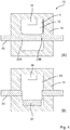
- FIG. 6 Figure 3 shows yet another embodiment of the invention.
- an expansion vessel 18 with a bellows is combined with a conductor 20, which in turn has two grooves, the grooves 22A and 22B.
- the free volume of the assembly above and / or below the conductor 20 can again be filled with a gaseous, liquid, powdery or gel-like extinguishing fluid (not shown here), including mixtures thereof.
- Fig. 7 shows a cross-sectional view of parts of a circuit breaker according to the invention which can be ignited passively.
- Fig. 8 offers schematic cross-sectional views of further advantageous conductor shapes as they can be used in the context of the present invention together with a quick disconnector. These conductors are particularly suitable for disconnectors that can be passively ignited, as in Fig. 7 shown.
- View (B) shows an alternative design of the conductor in which four symmetrical slots are provided, slots 22A, 22B, 22C and 22D. These grooves also define a conductor section which can easily be moved transversely.
- the view (C) shows a ladder with a deep blind hole 40.
- This blind hole can easily accommodate an expansion vessel. No additional grooves are used.
- the view (D) shows a conductor 20 in which two notches 34A and 34B are provided. Unlike grooves, which are of constant depth, the notches widen upwards. Notches thus have the advantage that the conductor section 32 delimited by them can be displaced transversely more easily. Even with a very rapid movement, as is typical for an explosion, tilting or possible jamming of the conductor section 32 is thus efficiently avoided.
Abstract
Die vorliegende Erfindung betrifft einen Schnelltrennschalter, das heißt einen Schalter, mit dem man besonders schnell einen elektrischen Stromkreis trennen kann. Solche Schalter werden gelegentlich auch als pyrotechnische Trennvorrichtungen oder auch als elektrische Unterbrechungsschaltglieder bezeichnet. Insbesondere geht es um einen Schnelltrennschalter (10), der einen Stromzufuhrkontakt und einen Stromabfuhrkontakt aufweist, welche durch einen Leiter (20) verbunden sind, und bei dem der Leiter (20) durch eine Trennkammer (12) geführt wird, und in der Trennkammer (12) ein Dehngefäß (18) vorgesehen ist, welches durch eine Explosivladung ausgedehnt werden kann. Ferner geht es um ein Verfahren zur Nottrennung eines Stromkreises.The present invention relates to a quick disconnect switch, that is to say a switch with which an electrical circuit can be disconnected particularly quickly. Such switches are sometimes also referred to as pyrotechnic disconnection devices or also as electrical interruption switching elements. In particular, it concerns a quick disconnect switch (10) which has a power supply contact and a power discharge contact, which are connected by a conductor (20), and in which the conductor (20) is passed through a separating chamber (12) and in the separating chamber ( 12) an expansion vessel (18) is provided, which can be expanded by an explosive charge. It is also about a method for the emergency disconnection of a circuit.
Description
Die vorliegende Erfindung bezieht sich auf einen Schnelltrennschalter, d. h. einen Schalter, mit dem man besonders schnell einen elektrischen Stromkreis auch bei hohen Stromstärken und hohen Trennspannungen trennen kann. Der Schalter eignet sich für Gleichstrom- und für Wechselstromkreise. Der Schalter setzt hierzu in der Regel eine geringe Menge eines Explosivstoffmaterials ein. Solche Schalter werden gelegentlich auch als pyrotechnische Trennvorrichtungen oder auch als elektrische Unterbrechungsschaltglieder bezeichnet. Sie können etwa auf dem immer wichtiger werdenden Gebiet der E-Mobilität insbesondere zur Absicherung elektrischer Antriebe eingesetzt werden, besonders bei Elektroautos, Elektrolastkraftwagen oder Elektrobussen. Wenn ein entsprechend angetriebenes Fahrzeug verunfallt, ist die schnelle Abtrennung der Stromquelle von der Fahrzeugverkabelung wichtig und notwendig. Die entsprechenden Fragen stellen sich auch beim Antrieb von Schiffen mit Elektromotoren oder inzwischen auch beim Antrieb von Flugzeugen mit Elektromotoren, aber auch bei entsprechenden Aufgabenstellungen in Schaltschränken allgemein.The present invention relates to a quick disconnect switch, i. H. a switch with which you can disconnect an electrical circuit particularly quickly, even with high currents and high separation voltages. The switch is suitable for both DC and AC circuits. The switch usually uses a small amount of an explosive material for this purpose. Such switches are sometimes also referred to as pyrotechnic disconnection devices or also as electrical interruption switching elements. For example, they can be used in the increasingly important field of e-mobility, in particular to protect electric drives, especially in electric cars, electric trucks or electric buses. If an appropriately powered vehicle has an accident, it is important and necessary to quickly disconnect the power source from the vehicle wiring. The corresponding questions also arise when propelling ships with electric motors or, in the meantime, when propelling aircraft with electric motors, but also when it comes to corresponding tasks in control cabinets in general.
Viele Trennschalter verwenden die Wirkung von Treibladungen auf einen Kolben. Nach dessen Beschleunigung und durch den auf ihn ausgeübten Druck sind sie jedenfalls in der Lage, damit einen Stromkreis schnell zu unterbrechen, auch dann, wenn hohe Ströme fließen.Many circuit breakers use the action of propellant charges on a piston. After its acceleration and the pressure exerted on it, they are in any case able to quickly interrupt a circuit, even when high currents are flowing.
Die Europäische Patentanmeldung
Die Deutsche Offenlegungsschrift
Die Deutsche Patentschrift
Diese Lösungen funktionieren allesamt nach dem Grundprinzip eines kolbengetriebenen Trennschalters. Da es auf die sehr schnelle Trennung eines Stromkreises innerhalb von Millisekunden ankommt, ist die Beschleunigung der Kolbenmasse aber von Nachteil. Eine Masse zu beschleunigen, verzögert den Prozess unvermeidlich. Ferner muss der Kolben in einer jeweiligen Trennkammer sauber geführt werden, um eine schnelle Bewegung zu ermöglichen. Darüber hinaus ist es noch erforderlich, Abdichtungsvorrichtungen vorzusehen, beispielsweise zwischen Kolben und Treibladung.These solutions all work on the basic principle of a piston-operated disconnector. Since it depends on the very fast separation of a circuit within milliseconds, the acceleration of the piston mass is a disadvantage. Accelerating a mass inevitably delays the process. Furthermore, the piston must be guided cleanly in a respective separation chamber in order to enable rapid movement. In addition, it is also necessary to provide sealing devices, for example between the piston and propellant charge.
Die Deutsche Offenlegungsschrift
Ebenfalls verläuft die Trennung der Leiter nicht in einer gut definierten Weise. Bei einer unzureichenden Trennung kann es daher sehr schnell zu Lichtbogenausbildungen kommen.Also, the separation of the conductors is not in a well-defined way. If the separation is inadequate, arcing can therefore occur very quickly.
Die vorliegende Erfindung möchte einen preiswert und zuverlässig herstellbaren Schnelltrennschalter anbieten, welcher die Nachteile im Stande der Technik umgeht. Insbesondere kann der Trennschalter kolbenfrei arbeiten, so dass eine Trennung mit wenig beschleunigter Masse möglich ist. Die Trennung soll den zu trennenden Leiter in einen zuverlässigen vordefinierten Trennzustand überführen und hierbei Lichtbogeneffekte minimieren, wie sie vor allem in Gleichstromkreisen (DC-Stromkreisen) bei der Stromkreistrennung auftreten würden. Ferner soll das Austreten von Abgasen der Treibladung oder Verschmutzungspartikeln vermieden werden, wie auch der Kontakt der Abgase mit der bzw. den Trennstellen.The present invention would like to offer a quick disconnector that can be manufactured inexpensively and reliably, which avoids the disadvantages of the prior art. In particular, the disconnector can work piston-free, so that a disconnection with less accelerated mass is possible. The separation is intended to bring the conductor to be separated into a reliable, predefined separation state and thereby minimize arc effects, such as would occur especially in direct current circuits (DC circuits) when the electrical circuit is disconnected. Furthermore, the escape of exhaust gases from the propellant charge or pollution particles should be avoided, as well as contact of the exhaust gases with the separation point (s).
Diese Aufgabe wird durch einen Schnelltrennschalter nach Anspruch 1 gelöst. Vorteilhafte Weiterbildungen sind in den Unteransprüchen angegeben. Die entsprechenden Vorteile weist auch ein Verfahren zur Stromkreistrennung nach Verfahrensanspruch 11 und seinen Unteransprüchen auf.This object is achieved by a quick disconnect switch according to
Der Schnelltrennschalter soll einen Stromzuführkontakt und einen Stromabfuhrkontakt aufweisen. Diese Bezeichnungen sollen allerdings nicht zwingend eine Stromrichtung festlegen, in der Regel kann der Trennschalter unabhängig von einer bestimmten Stromrichtung wirksam werden. Diese Kontakte können unmittelbar am Trennschalter vorgesehen sein, oder der Trennschalter kann auch Leitungsabschnitte aufweisen, die ihrerseits erst diese Kontakte aufweisen. Die beiden Kontakte sind durch einen Leiter verbunden. Hierbei handelt es sich oft um einen Kupfer- oder Aluminiumleiter. Ein anderes Material, insbesondere ein anderes metallisches oder zumindest elektrisch leitfähiges Material, ist aber ebenfalls geeignet.The quick-disconnect switch should have a power supply contact and a power discharge contact. However, these designations should not necessarily define a current direction; as a rule, the disconnector can operate independently of a specific current direction. These contacts can be provided directly on the disconnector, or the disconnector can also have line sections which in turn first have these contacts. The two contacts are connected by a conductor. This is often a copper or aluminum conductor. Another material, in particular another metallic or at least electrically conductive material, is also suitable.
Der Schnelltrennschalter weist eine Trennkammer auf. Diese weist ihrerseits einen Innenraum auf. Der Innenraum kann verschiedene Formen haben, häufig ist er quaderförmig. Der Leiter wird durch die Trennkammer geführt. Vorzugsweise wird der Leiter genau oder im Wesentlichen mittig durch die Trennkammer geführt. Damit ergibt sich zumindest in einer Schnittebene eine spiegelsymmetrische Lage.The quick disconnector has a separation chamber. This in turn has an interior. The interior can have different shapes, often it is cuboid. The conductor is led through the separation chamber. The conductor is preferably passed through the separating chamber precisely or essentially in the middle. This results in a mirror-symmetrical position at least in one sectional plane.
Erfindungsgemäß ist in der Trennkammer ein Dehngefäß vorgesehen. Das Dehngefäß kann eine Explosivladung enthalten. Alternativ kann die Explosivladung in einem an das Dehngefäß angrenzenden Gefäß untergebracht sein, beispielsweise zusammen mit einer Zündladung. In jedem Fall soll bei Explosion die Explosivladung das Dehngefäß ausdehnen können.According to the invention, an expansion vessel is provided in the separation chamber. The expansion vessel can contain an explosive charge. Alternatively, the explosive charge can be accommodated in a vessel adjoining the expansion vessel, for example together with an ignition charge. In any case, the explosive charge should be able to expand the expansion vessel in the event of an explosion.
Anders als im Stand der Technik ist die Explosivladung also nicht unmittelbar in der Trennkammer vorgesehen, sondern in einem eigenen Gefäß.In contrast to the prior art, the explosive charge is therefore not provided directly in the separation chamber, but in its own vessel.
Die Explosion der Explosivladung bewirkt die mechanische Trennung des Leiters. Dies geschieht unter Ausdehnung des Dehngefäßes. Das Dehngefäß kann dabei die Explosivladung auch nach der Explosion vollständig umschließen.The explosion of the explosive charge causes the mechanical separation of the conductor. This takes place with expansion of the expansion vessel. The expansion vessel can completely enclose the explosive charge even after the explosion.
Dieser Aspekt führt zu weiteren grundsätzlichen Vorteilen der Erfindung: Der Trennschalter kann gasdicht gebaut werden und deshalb bei sehr niedrigen Umgebungsdrücken (z.B. in der Luftfahrt) eingesetzt werden. Bei Schaltern aus dem Stand der Technik muss Abgas entweichen können. Daher können diese Schalter nicht gasdicht gebaut und bei sehr niedrigen Umgebungsdrücken eingesetzt werden.This aspect leads to further fundamental advantages of the invention: The disconnector can be built gas-tight and can therefore be used at very low ambient pressures (e.g. in aviation). With switches from the state of the art, exhaust gas must be able to escape. Therefore, these switches cannot be built gas-tight and can be used at very low ambient pressures.
Das Dehngefäß kann beispielsweise einen Faltenbalg umfassen. Ein solcher Faltenbalg erleichtert die schnelle Ausdehnung. Das Dehngefäß soll sich beispielsweise auf mehr als 200%, 300%, 400%, 500% oder bis zu 1000% seines Ausgangsvolumens ausdehnen können. Vorzugsweise soll dies zerstörungsfrei geschehen. Das Dehngefäß kann auch elastisch sein, so dass sich sein Volumen nach der Explosion wieder reduziert. Elastizität ist jedoch nicht erforderlich. Das Dehngefäß kann zweckmäßigerweise aus Metall oder aus einem Nicht-Metall gefertigt werden. Zweckmäßige Metalle sind Stähle, allgemein dünne Stähle, und insbesondere auch Edelstahl. Alternativ kann das Dehngefäß auch aus Bronze oder Kupfer gefertigt werden. Bei den NichtMetallen sind Gummi, Naturgummi, Silikon oder auch TPE-Kunststoff zweckmäßig. In Betracht kommen ebenfalls Kunststoffe wie Polyoxymethylen (POM), Polyamid 6 (PA 6) oder ABS.The expansion vessel can comprise a bellows, for example. Such a bellows facilitates rapid expansion. The expansion vessel should be able to expand, for example, to more than 200%, 300%, 400%, 500% or up to 1000% of its initial volume. Preferably this should happen non-destructively. The expansion vessel can also be elastic, so that its volume is reduced again after the explosion. However, elasticity is not required. The expansion vessel can expediently be made of metal or of a non-metal. Appropriate metals are steels, generally thin steels, and in particular also stainless steel. Alternatively, the expansion vessel can also be made of bronze or copper. In the case of non-metals, rubber, natural rubber, silicone or even TPE plastic are useful. Plastics such as polyoxymethylene (POM), polyamide 6 (PA 6) or ABS can also be considered.
Wenn für das Dehngefäß ein elektrisch leitendes Material verwendet wird, muss dieses in der Regel außen elektrisch durch eine elektrisch nichtleitende Schicht abisoliert werden, um nach dem Trennen des Leiters die verbleibenden Kontaktstücke nicht elektrisch zu überbrücken.If an electrically conductive material is used for the expansion vessel, this usually has to be electrically stripped on the outside by an electrically non-conductive layer so that the remaining contact pieces are not electrically bridged after the conductor has been separated.
Das Dehngefäß ist zweckmäßigerweise leichter als der in der Trennkammer verlaufende Leiterabschnitt. Durch dieses geringe Gewicht ist eine schnelle Ausdehnung der Explosivladung auch im Verhältnis zur Masse des durchtrennenden Leiterabschnittes gegeben. Ein eher schweres Dehngefäß würde eine Durchtrennung des Leiters nach Art eines Kolbens bewirken. Ein Dehngefäß aus Metall kann in entsprechender Weise gestaltet werden. Jedoch würde die Leitertrennung etwa durch einen scharfkantigen kolbenähnlichen Abschnitt im Rahmen der vorliegenden Erfindung nicht erforderlich sein. Die Leitertrennung erfolgt vorwiegend durch die rasche Ausdehnung des Explosivmaterials im vorgegebenen Raum der Trennkammer, anders gesagt durch eine Druckwelle.The expansion vessel is expediently lighter than the conductor section running in the separating chamber. This low weight enables the explosive charge to expand rapidly, also in relation to the mass of the conductor section to be severed. A rather heavy expansion vessel would cause the conductor to be severed in the manner of a piston. A metal expansion vessel can be designed in a corresponding manner. However, the conductor separation, for example by means of a sharp-edged piston-like section, would not be necessary in the context of the present invention. The conductors are separated mainly through the rapid expansion of the explosive material in the given space of the separation chamber, in other words through a pressure wave.
Es ist zweckmäßig, wenn der Leiter entlang einer Achse in einer ersten Richtung durch die Trennkammer verläuft. Die Trennkammer und insbesondere die Lage des Dehngefäßes kann zweckmäßig so gestaltet werden, dass die Trennung mit einer bezogen auf diese Achse ganz, oder im Wesentlichen, oder zumindest überwiegenden radialen Komponente erfolgt.It is expedient if the conductor runs along an axis in a first direction through the separating chamber. The separating chamber and in particular the position of the expansion vessel can expediently be designed in such a way that the separation takes place with a completely, substantially, or at least predominant radial component in relation to this axis.
Dann kann ein abzutrennender Leiterabschnitt radial verschoben werden. Dabei kann der Leiter verbogen werden, so dass nur ein gewisses Teilstück radial verschoben wird, oder es kann aus dem Leiter an zwei Seiten ein Teilstück abgetrennt werden, welches insgesamt radial verschoben wird.A conductor section to be separated can then be displaced radially. The conductor can be bent so that only a certain section is displaced radially, or a section can be separated from the conductor on two sides, which is displaced radially as a whole.
Es kann zweckmäßig sein, wenn der Leiter mechanische Schwächungselemente aufweicht. Solche Schwächungselemente reduzieren das zu trennende Leitermaterial, ohne den elektrischen Durchgangswiderstand des Leitermaterials wesentlich zu erhöhen. Diese Schwächungselemente können Bohrungen, Nuten, Teilschnitte oder Kerben umfassen. Sie dienen auch dazu, die Trennung des Leiters im Voraus berechenbar zu machen, zu erleichtern und im Voraus in günstiger Weise zu gestalten.It can be useful if the conductor softens mechanical weakening elements. Such weakening elements reduce the conductor material to be separated without significantly increasing the electrical volume resistance of the conductor material. These weakening elements can include bores, grooves, partial cuts or notches. They also serve to make the separation of the conductor predictable in advance, to facilitate it and to organize it in advance in a favorable manner.
Eine Bohrung hat den zusätzlichen Nutzen, dass sie eine Luftströmung durch den Leiter ermöglicht. Bei einer schnellen Bewegung des Leiters oder eines Leiterabstands entsteht damit weniger Strömungswiderstand. Auch wenn der Leiter sich in ein Löschmedium hinein bewegt, kann durch die Bohrung der Strömungswiderstand und damit der Widerstand gegen die gewünschte Translationsbewegung des Leiters deutlich reduziert werden. Im Übrigen sind Bohrungen durch die Entnahme des Materials Schwächungsstellen, an denen besonders leicht eine Bruchstelle im Material entstehen kann.Drilling has the added benefit of allowing air to flow through the conductor. With a fast movement of the conductor or a distance between the conductors, there is less flow resistance. Even if the conductor moves into an extinguishing medium, the flow resistance and thus the resistance to the desired translational movement of the conductor can be significantly reduced through the bore. Incidentally, holes caused by the removal of the material are weak points at which a break point in the material can occur particularly easily.
Im Übrigen können Schwächungselemente in Form von Nuten oder Kerben vorgesehen werden. Unter einer Nut soll hierin eine Schlitzung von bestimmter Tiefe verstanden werden (welche im Querschnitt als Sackloch erscheint), welche aber im Querschnitt auch eine gleichmäßige Dicke hat. Unter einer Kerbe soll eine Vertiefung verstanden werden, welche nahe der Leiteroberfläche breiter ist als in größerer Tiefe. Beides sind geeignete Schwächungselemente. Kerben erlauben es vorteilhaft, ganze Abschnitte des Leiters radial zu verschieben. Wenn nur eine Nut vorgesehen ist, insbesondere eine schmale Nut, kann die radiale Verschiebung durch eine Verkippung und Verkantung erschwert oder behindert werden.In addition, weakening elements in the form of grooves or notches can be provided. A groove is to be understood here as a slot of a certain depth (which appears as a blind hole in cross section), but which also has a uniform thickness in cross section. A notch should be understood to mean a depression which is wider near the conductor surface than at a greater depth. Both are suitable attenuation elements. Notches advantageously allow entire sections of the conductor to be displaced radially. If only one groove is provided, in particular a narrow groove, the radial displacement can be made difficult or hindered by tilting and tilting.
Der Leiter kann auch eine Zone erhöhten Widerstandes aufweisen. Beispielsweise kann der Leiterdurchmesser in einer solchen Zone verringert sein. Zur Erhöhung des elektrischen Widerstandes können die oben aufgezählten Schwächungselemente zweckmäßig eingesetzt werden. Dies führt zu einer elektrischen Erhitzung des Leiters. Die entstehende Wärme kann genutzt werden, um dort anliegendes Explosivmaterial zu zünden. Dazu wird das Explosivmaterial vorzugsweise in der Nähe der Zone des erhöhten Widerstandes und in gutem thermischem Kontakt zu ihr positioniert.The conductor can also have a zone of increased resistance. For example, the conductor diameter can be reduced in such a zone. The weakening elements enumerated above can expediently be used to increase the electrical resistance. This leads to electrical heating of the conductor. The resulting heat can be used to ignite explosive material lying there. For this purpose, the explosive material is preferably positioned in the vicinity of the zone of increased resistance and in good thermal contact with it.
Es besteht auch die vorteilhafte Möglichkeit, das Material des Dehngefäßes auf eine solche Wärme-ausgelöste oder "passive" Explosion hin zu optimieren. Dabei kann das Material des Dehngefäßes insgesamt dieser Aufgabe angepasst werden, oder das Dehngefäß weist abschnittsweise, nämlich an der Kontaktfläche mit dem Leiter, ein vom übrigen Dehngefäß abweichendes Material auf. Geeignete Materialien sind hierbei Kupfer, Messing, Aluminium, Silber oder auch Bronze.There is also the advantageous possibility of optimizing the material of the expansion vessel for such a heat-triggered or "passive" explosion. The material of the expansion vessel can be adapted to this task as a whole, or the expansion vessel has in sections, namely at the contact surface with the conductor, a material that differs from the rest of the expansion vessel. Suitable materials here are copper, brass, aluminum, silver or bronze.
Es kommt auch in Frage, wenn am Dehngefäß eine zusätzliche Kontaktlage aufgebracht wird. Beispielsweise könnte eine Kontaktlage aus Kupfer zur besonders guten Wärmeleitung eingesetzt werden. In dieser Weise lässt sich die Wärme-induzierte Trennung besonders exakt den Notwendigkeiten des Schaltkreises anpassen.It is also possible if an additional contact layer is applied to the expansion vessel. For example, a contact layer made of copper could be used for particularly good heat conduction. In this way, the heat-induced separation can be adapted particularly precisely to the needs of the circuit.
Diese zweckmäßige Gestaltung zeigt weitere Vorteile der Verwendung eines Dehngefäßes auf. Wo etwa ein Kolben verwendet wird, muss der Kolben fast unvermeidlich zwischen Explosivladung und Leiter angewandt werden. Damit verhindert aber der Kolben eine örtlich nahe Positionierung der Explosivladung am Leiter. Durch Verzicht auf einen Kolben ist dies möglich. Die Auslösung der Stromkreistrennung durch Leitererwärmung ist besonders vorteilhaft. Sie ermöglicht durch die hier vorhandene passive Auslösung der Explosivladung bzw. des Trennschalters, dass eine Überhitzung des Stromkreises oder einer hier kurzgeschlossenen Stromquelle durch zu hohe Ströme vermieden wird, ohne dass eine komplizierte Erfassung und Auswertung der Ströme und/oder Schaltung erforderlich sind.This expedient design shows further advantages of using an expansion vessel. For example, where a piston is used, the piston must almost inevitably be applied between the explosive charge and the conductor. In this way, however, the piston prevents the explosive charge from being positioned close to the conductor. This is possible by dispensing with a piston. The triggering of the circuit disconnection by heating the conductor is particularly advantageous. they Thanks to the passive triggering of the explosive charge or the disconnector, which is present here, overheating of the circuit or a short-circuited power source due to excessively high currents is avoided without the need for complicated recording and evaluation of the currents and / or switching.
Es kann auch zweckmäßig sein, Teile der Explosivladung innerhalb des Dehngefäßes vorzusehen und Teile der Explosivladung außerhalb des Dehngefäßes vorzusehen. Beispielsweise kann eine Explosivladung in einem Sackloch oder einer ähnlichen Ausnehmung des Leiters vorgesehen sein. Diese Explosivladung erwärmt sich dann durch den unmittelbaren Kontakt zum Leiter schnell. Ihre Explosion kann durch Wärmeübertragung die Explosion der übrigen Explosivladung im Trenngefäß bewirken. Dazu kann beispielsweise auch zusätzlich eine Bohrung vorgesehen werden, durch die ein Heißgasstrahl das Innere des Dehngefäßes erreicht. Eine solche Bohrung ist nicht unbedingt erforderlich, da auch durch thermische Erwärmung durch das Material des Dehngefäßes hindurch schnell und zuverlässig eine Explosion von Explosivmaterial ausgelöst werden kann, welche innerhalb des Dehngefäßes vorgesehen ist.It can also be expedient to provide parts of the explosive charge inside the expansion vessel and to provide parts of the explosive charge outside the expansion vessel. For example, an explosive charge can be provided in a blind hole or a similar recess in the conductor. This explosive charge then heats up quickly through direct contact with the conductor. Their explosion can cause the remaining explosive charge in the separation vessel to explode through heat transfer. For this purpose, a bore can also be provided, for example, through which a jet of hot gas reaches the interior of the expansion vessel. Such a bore is not absolutely necessary, since an explosion of explosive material, which is provided inside the expansion vessel, can also be triggered quickly and reliably by thermal heating through the material of the expansion vessel.
Nach einer weiteren vorteilhaften Gestaltung der Erfindung kann die Trennkammer ein Löschmedium umfassen. Dieses Löschmedium kann beispielsweise unterhalb des Leiters angeordnet sein, das heißt auf der dem Dehngefäß abgewandten Seite vom Leiter - oder es füllt gleich mehr oder weniger den gesamten Innenraum des Trennschalters außerhalb des Dehngefäßes aus. Hierbei sind Füllgrade von 10% bis nahe 100% des freien inneren Volumens des Trennschalters von Vorteil.According to a further advantageous embodiment of the invention, the separating chamber can comprise an extinguishing medium. This extinguishing medium can for example be arranged below the conductor, that is to say on the side of the conductor facing away from the expansion vessel - or it fills more or less the entire interior of the disconnector outside the expansion vessel. Fill levels of 10% to almost 100% of the free internal volume of the disconnector are advantageous here.
Die vorliegende Erfindung bezieht sich auch auf ein Verfahren zur Nottrennung eines Stromkreises, welches folgende Schritte umfasst:
- a. Führen des Stromes durch einen Leiterabschnitt
- b. Führen des Leiterabschnitts durch eine Trennkammer
- c. Vorsehen eines Dehngefäßes in der Trennkammer
- d. Vorhalten eines Explosivmaterials am oder im Dehngefäß
- e. Zünden des Explosivmaterials
- f. Durchtrennen des Leiterabschnittes
- a. Passing the current through a section of conductor
- b. Passing the conductor section through a separation chamber
- c. Providing an expansion vessel in the separation chamber
- d. Holding an explosive material on or in the expansion vessel
- e. Detonation of the explosive material
- f. severing the conductor section
Das Explosivmaterial soll so am oder im Dehngefäß vorgehalten werden, dass das Dehngefäß durch die Reaktion des Explosivmaterial ausgedehnt werden kann.The explosive material should be held on or in the expansion vessel in such a way that the expansion vessel can be expanded by the reaction of the explosive material.
Vorzugsweise werden die Schritte im Zusammenhang und in der Reihenfolge ihrer Aufzählung ausgeführt. Das Verfahren ist auf den erfindungsgemäßen Schnelltrennschalter bezogen zu verstehen. Das heißt, Merkmale der Gestaltung des Schnelltrennschalters sind analog auf das Verfahren zu übertragen, und Merkmale des Verfahrens sind analog auf Merkmale des Schnelltrenners zu übertragen.The steps are preferably carried out in context and in the order in which they are listed. The method is to be understood in relation to the quick disconnector according to the invention. This means that features of the design of the quick disconnector are to be transferred analogously to the method, and characteristics of the method are to be transferred analogously to characteristics of the quick disconnector.
Zweckmäßig ist auch ein Verfahren, in dem das Explosivmaterial nach der Explosion vollständig in dem Gefäß verbleibt.A method in which the explosive material remains completely in the vessel after the explosion is also expedient.
Zweckmäßig ist ferner ein Verfahren, bei dem nach dem Durchtrennen des Leiters ein erstes Leiterende und ein zweites Leiterende entsteht, und das Dehngefäß das erste Leiterende und das zweite Leiterende mechanisch trennt. Das Dehngefäß dehnt sich also zwischen den Leiterenden aus. Allgemein soll unter mechanischer Trennung hieran verstanden werden, dass das Dehngefäß eine gedachte Verbindungslinie zwischen den Leiterenden durchtrennt und/oder entlang die ursprüngliche axiale Verlaufsachse des Leiters durchtrennt.A method is also expedient in which, after the conductor has been severed, a first conductor end and a second conductor end are produced, and the expansion vessel mechanically separates the first conductor end and the second conductor end. The expansion vessel thus expands between the ends of the conductor. In general, mechanical separation should be understood to mean that the expansion vessel cuts through an imaginary connecting line between the conductor ends and / or cuts along the original axial axis of the conductor.
Zweckmäßig ist insbesondere auch ein Verfahren, bei dem das Explosivmaterial durch einen elektrischen Zündimpuls gezündet wird. Alternativ oder zusätzlich, in der Regel aber alternativ, kann das Explosivmaterial durch Erhitzung eines Leiterabschnittes gezündet werden. Dabei kommt insbesondere ein Leiterabschnitt mit einem erhöhten elektrischen Widerstand in Betracht.In particular, a method in which the explosive material is ignited by an electrical ignition pulse is also expedient. As an alternative or in addition, but generally as an alternative, the explosive material can be ignited by heating a conductor section. In particular, a conductor section with an increased electrical resistance comes into consideration.
Zweckmäßigerweise geht es auch um ein Verfahren, bei dem sich das Dehngefäß ganz oder abschnittsweise an Innenwände der Trennkammer schmiegt.Expediently, it is also a question of a method in which the expansion vessel nestles entirely or in sections against the inner walls of the separating chamber.
Vor der Explosion befindet sich das Dehngefäß in einem Teilvolumen der Trennkammer. Zweckmäßigerweise macht dieses Teilvolumen weniger als 80% oder auch weniger als 60% oder auch weniger als 40% des Gesamtvolumens der Trennkammer aus.Before the explosion, the expansion vessel is located in a partial volume of the separation chamber. This partial volume expediently makes up less than 80% or also less than 60% or also less than 40% of the total volume of the separation chamber.
Die Trennkammer soll ferner ein sogenanntes erstes Volumen haben. Dieses Volumen wird auch die Fläche, die den Leiter mittig durchtrennt und senkrecht zur Ausdehnungsrichtung des Dehngefäßes steht, begrenzt. Das erste Volumen soll das Dehngefäß enthalten. Bezogen auf das erste Volumen ist es zweckmäßig, wenn das Dehngefäß weniger als 80% oder 60% oder auch 40% des ersten Volumens einnimmt.The separation chamber should also have a so-called first volume. This volume is also limited to the area that cuts the conductor in the middle and is perpendicular to the expansion direction of the expansion vessel. The first volume should contain the expansion vessel. In relation to the first volume, it is useful if the expansion vessel occupies less than 80% or 60% or even 40% of the first volume.
Nach der Explosion füllt das Dehngefäß ein größeres Volumen der Trennkammer auf. Dabei kann es beinahe das volle Volumen der Trennkammer ausfüllen und sich dann fast vollständig oder vollständig an die Innenwände der Trennkammer anschmiegen. Alternativ geschieht dies zumindest abschnittsweise. Das Anschmiegen an die Innenwände der Trennkammer und die entsprechende Auswahl und Positionierung des Dehngefäßes erleichtern es, dass die Dehngefäßwände nicht bersten oder anders undicht werden. Das Dehngefäß muss sich dann nur in der Explosionsphase mit der sich ausdehnenden Front des Treibmaterials mitbewegen, bis es an einen Trennwandabschnitt stößt. Der Druck der Explosion wird ab diesem Zeitpunkt durch die Innenwände oder zumindest einem Innenwandabschnitt der Trennkammer aufgenommen. Dementsprechend müssen die Wände des Dehngefäßes, obwohl sie einer Explosion gewissermaßen standhalten müssen, nicht übermäßig stabil sein. Es genügt, wenn das Material an sich nicht sehr (druck-) belastbar, aber schnell dehnbar ist. Das gilt insbesondere für Gummimaterialien. Das Dehngefäß kann dann eine Art Ballon bilden, der für eine einmalige schnelle Dehnung ausgelegt ist, aber großen Drücken nicht oder jedenfalls nicht unbedingt auf Dauer standhalten muss.After the explosion, the expansion vessel fills a larger volume of the separation chamber. It can fill almost the full volume of the separation chamber and then almost completely or completely cling to the inner walls of the separation chamber. Alternatively, this is done at least in sections. Nestling against the inner walls of the separation chamber and the appropriate selection and positioning of the expansion vessel make it easier for the expansion vessel walls not to burst or otherwise leak. The expansion vessel then only has to move with the expanding front of the propellant material in the explosion phase move with it until it hits a partition wall section. From this point in time, the pressure of the explosion is absorbed by the inner walls or at least one inner wall section of the separation chamber. Accordingly, although the walls of the expansion vessel must be able to withstand an explosion, they do not have to be overly stable. It is sufficient if the material itself is not very (pressure) resilient, but can be stretched quickly. This is especially true for rubber materials. The expansion vessel can then form a kind of balloon, which is designed for a one-time rapid expansion, but does not have to withstand large pressures, or at least does not necessarily have to withstand long-term.
Als Explosivladung wird hier allgemein ein Stoff verstanden, welcher sich bei einer entsprechenden Aktivierung schnell und stark ausdehnt. Es kommt ein Stoff oder auch Stoffgemisch in Frage, welcher durch inneren Druck die Dehnung des Dehngefäßes bewirken kann. Dabei können Gase oder Dämpfe erzeugt werden. Zweckmäßig sind hier Nitrozellulosepulver oder Double Base Pulver (diese sind Mischungen aus NC und NGL), aber vor allem die bekannten Zünd- und Anzündstoffe wie ZPP (Zirkonium Potassium Perchlorat), Silberazid, Hexogen oder auch Oktogen.An explosive charge is generally understood here to be a substance which, when activated, expands rapidly and strongly. A substance or a mixture of substances comes into question, which can cause the expansion of the expansion vessel through internal pressure. This can generate gases or vapors. Nitrocellulose powder or double base powder (these are mixtures of NC and NGL) are useful here, but above all the well-known igniting substances such as ZPP (zirconium potassium perchlorate), silver azide, hexogen or octogen.
Bleihaltige Mischungen wie Bleiazid könnten zwar ebenfalls eingesetzt werden, jedoch will und sollte man hier schwermetallfrei bleiben. Auch Gase oder insbesondere auch in flüssiger Form können hier verwendet werden.Mixtures containing lead, such as lead azide, could also be used, but you want and should stay free of heavy metals here. Gases or especially in liquid form can also be used here.
Die Aktivierung erfolgt in der Regel durch einen Anzünder oder einen Zünder. Der Anzünder kann einen Hitzedraht oder Explosionsdraht beinhalten oder auch durch eine elektrische Entladung gezündet werden. Einem Gas kann auch ein fester, oder flüssiger, oder anderer gasförmiger Stoff beigemischt werden, insbesondere ein Oxidationsmittel. Alternativ oder zusätzlich kann eine Explosion auch passiv ausgelöst werden, das heißt durch die bloße Erwärmung eines Explosivstoffes. Dabei kann auch in zwei Bereichen Explosivstoff vorgesehen sein, wobei zunächst ein erster Explosivstoff zur Explosion gebracht wird und diese Explosion die Explosion eines zweiten Explosivstoffes auslöst.Activation is usually carried out by a lighter or a detonator. The igniter can contain a hot wire or an explosion wire, or it can be ignited by an electrical discharge. A solid, liquid or other gaseous substance can also be added to a gas, in particular an oxidizing agent. Alternatively or additionally, an explosion can also be triggered passively, that is, by simply heating an explosive. In this case, explosive material can also be provided in two areas, with a first explosive material initially being used Explosion is brought and this explosion triggers the explosion of a second explosive.
Das optional vorgesehene Löschmittel sollte auf die Explosivladung abgestimmt sein. Grundsätzlich kann es flüssig, gasförmig, gelartig, schaumartig oder auch mehrfaserig sein.The optionally provided extinguishing agent should be matched to the explosive charge. Basically, it can be liquid, gaseous, gel-like, foam-like or multi-fiber.
Weitere Merkmale, aber auch Vorteile der Erfindung, ergeben sich aus den nachfolgend aufgeführten Zeichnungen und der zugehörigen Beschreibung. In den Abbildungen und in den dazugehörigen Beschreibungen sind Merkmale der Erfindung in Kombination beschrieben. Diese Merkmale können allerdings auch in anderen Kombinationen von einem erfindungsgemäßen Gegenstand umfasst werden. Jedes offenbarte Merkmal ist also auch als in technisch sinnvollen Kombinationen mit anderen Merkmalen offenbart zu betrachten. Die Abbildungen sind teilweise leicht vereinfacht und schematisch:
- Fig. 1
- ist eine Querschnittsdarstellung eines erfindungsgemäßen Trennschalters, welcher in Ansicht (A) vor der Trennung und in Ansicht (B) nach der Trennung gezeigt wird.
- Fig. 2
- ist eine Querschnittsansicht eines alternativen erfindungsgemäßen Trennschalters, welcher in Ansicht (A) vor der Trennung und in Ansicht (B) nach der Trennung gezeigt wird.
- Fig. 3
- ist eine Querschnittsansicht eines alternativen erfindungsgemäßen Trennschalters, welcher in Ansicht (A) vor der Trennung und in Ansicht (B) nach der Trennung gezeigt wird.
- Fig. 4
- ist eine Querschnittsansicht eines alternativen erfindungsgemäßen Trennschalters, welcher in Ansicht (A) vor der Trennung und in Ansicht (B) nach der Trennung gezeigt wird.
- Fig. 5
- ist eine Querschnittsansicht eines alternativen erfindungsgemäßen Trennschalters, welcher in Ansicht (A) vor der Trennung und in Ansicht (B) nach der Trennung gezeigt wird.
- Fig. 6
- ist eine Querschnittsansicht eines alternativen erfindungsgemäßen Trennschalters, welcher in Ansicht (A) vor der Trennung und in Ansicht (B) nach der Trennung gezeigt wird.
- Fig. 7
- zeigt eine Querschnittsansicht von Teilen eines erfindungsgemäßen Trennschalters, welcher passiv gezündet werden kann.
- Fig. 8
- bietet Querschnittsansichten verschiedener Leiter, welche jeweils unterschiedliche Schwächungselemente aufweisen.
- Fig. 1
- is a cross-sectional view of a circuit breaker according to the invention, which is shown in view (A) before disconnection and in view (B) after disconnection.
- Fig. 2
- Figure 3 is a cross-sectional view of an alternative circuit breaker according to the invention, shown in view (A) before disconnection and in view (B) after disconnection.
- Fig. 3
- Figure 3 is a cross-sectional view of an alternative circuit breaker according to the invention, shown in view (A) before disconnection and in view (B) after disconnection.
- Fig. 4
- Figure 3 is a cross-sectional view of an alternative circuit breaker according to the invention, shown in view (A) before disconnection and in view (B) after disconnection.
- Fig. 5
- Figure 3 is a cross-sectional view of an alternative circuit breaker according to the invention, shown in view (A) before disconnection and in view (B) after disconnection.
- Fig. 6
- Figure 3 is a cross-sectional view of an alternative circuit breaker according to the invention, shown in view (A) before disconnection and in view (B) after disconnection.
- Fig. 7
- shows a cross-sectional view of parts of a circuit breaker according to the invention which can be ignited passively.
- Fig. 8
- offers cross-sectional views of different conductors, each with different weakening elements.
Der Schnelltrennschalter 10 weist die Trennkammer 12 auf, welche vom Trennkammergehäuse 14 umgeben ist. In der Trennkammer 12 ist ein Zündelement 16 angebracht. Anschließend an das Zündelement 16 ist das Dehngefäß 18 vorgesehen. Durch die Trennkammer verläuft der Leiter 20. Der Leiter 20 ist mit verschiedenen Schwächungselementen ausgerüstet, nämlich mit der Nut 22 sowie mit Bohrungen 24.The
Die Trennkammer 12 weist ein erstes Volumen V1 auf, welches in diesem Querschnitt nach unten durch den Leiter 20 begrenzt wird und im Übrigen durch die Wände der Trennkammer 12 begrenzt wird. Das Dehngefäß 18 nimmt nur einen kleinen Raum dieses ersten Volumens V1 ein, deutlich weniger als 50%.The
Ausgelöst durch eine Zündung kann es zu einer wesentlichen (explosionsartigen) Volumenvergrößerung des Dehngefäßes kommen. Das Dehngefäß 18 oder die Kammer um das Zündelement 16 enthält dazu ein nicht näher dargestelltes Explosivmaterial. Durch diese Explosion wird der Trennschalter 10 in den in der Ansicht (B) gezeigten Zustand überführt. (Unveränderte Elemente werden nicht mehr näher bezeichnet und erläutert.) Das Dehngefäß 18 nimmt nun ein wesentlich größeres Volumen ein. Der Leiter 20 ist durchtrennt. Dabei tritt die Biegung 26 auf. Dadurch wird der Leiter 20 an den Trennflächen 28a und 28b vollständig getrennt und ein Abstand zwischen den Trennflächen hergestellt, der einen elektrischen Überschlag vermeidet.Triggered by an ignition, there may be a significant (explosive) increase in volume of the expansion vessel. For this purpose, the
Zu bedenken ist, dass der erfindungsgemäße Trennschalter weitere Elemente umfassen kann. Er ist hier nur schematisch und leicht vereinfacht dargestellt. Beispielsweise könnten an den Leiterenden Klemmen vorgesehen sein, ferner kann das Zündelement in sich vielteilig sein. Der dargestellte Trennschalter 12 verwirklicht aber bereits alle wesentlichen Elemente der Erfindung.It should be borne in mind that the isolating switch according to the invention can comprise further elements. It is shown here only schematically and in a slightly simplified manner. For example, terminals could be provided at the conductor ends, and the ignition element itself can consist of many parts. The
Weiter kann das freie Volumen der Baugruppe über und/oder unterhalb des Leiters 20 mit einem hier nicht eingezeichneten gasförmigen, flüssigen, pulverigem oder gelartigen Löschfluid gefüllt sein, auch aus deren Mischungen.Furthermore, the free volume of the assembly above and / or below the
In Ansicht (B) ist die Situation nach der Explosion dargestellt. Das Dehngefäß 18 hat sich ausgedehnt, bei seiner Ausdehnung schmiegt es sich an die Innenwände der Trennkammer an und drückt gegen den Leiter 20. Dies führt analog zum Ausbilden einer Biegung 26 des Leiters. Das ausgedehnte Dehngefäß unterdrückt Funkenüberschlag besonders effizient.The situation after the explosion is shown in view (B). The
Auch in den in
Hierbei wird auf die Darstellung des Schnelltrennschalters 10 insgesamt verzichtet. Dargestellt ist der Leiter 20 und seine Zusammenwirkung mit dem Dehngefäß 18. Das dargestellte Dehngefäß 18 weist wiederum einen Faltenbalg 30 auf. Dies ist zweckmäßig, wenn das Dehngefäß aus Metall gefertigt ist. Bei einem Dehngefäß aus Gummi kann häufig darauf verzichtet werden, einen solchen Faltenbalg vorzusehen. Das Dehngefäß 18 ist in seinem unteren Bereich mit der Explosivladung 36 befüllt. Diese Explosivladung liegt über eine Kontaktbahn am Leiter an. Die Kontaktbahn 38 kann einstückig mit dem Dehngefäß gefertigt sein, oder als zusätzliche Bahn außen auf das Dehngefäß aufgebracht werden. Im Leiter 20 ist ein Sackloch 40 vorgesehen, welches das Dehngefäß teilweise aufnehmen kann. Zusätzlich sind im Leiter 20 Nuten 22A und 22B vorgesehen. Diese mechanische Situation führt zum einen zu einer mechanischen Schwächung des Leiters. Ferner wird durch das Sackloch 40 wie auch durch die Nuten 22A und 22B ein Bereich erhöhten elektrischen Widerstandes erzeugt. In diesem Bereich erwärmt sich der Leiter bei entsprechend hohem Stromfluss schnell.The
Die Geometrie bewirkt auch in vorteilhafter Weise, dass die Wärme sich schnell auf das Dehngefäß 18 überträgt und dort die Explosivladung 36 entzündet werden kann.The geometry also has the advantageous effect that the heat is quickly transferred to the
Wie schon erläutert, hier aber nicht dargestellt, kann es auch zweckmäßig sein, eine zweite Explosivladung außerhalb des Dehngefäßes 18 im Bereich des Sackloches und eventuell auch in den Nuten 22A und 22B vorzusehen. Durch bloße Wärmeübertragung ist die schnelle Zündung besonders eines solchen Explosivmaterials außerhalb des Dehngefäßes 18 möglich. Ein optional zusätzliches, auch innerhalb des Dehngefäßes vorgesehenes zweites Explosivmaterial wird dann durch das erste Explosivmaterial, welches außerhalb des Dehngefäßes 18 vorgesehen ist, besonders leicht entzündet.As already explained, but not shown here, it can also be expedient to provide a second explosive charge outside the
Handelt es sich bei dem Faltenbalg bzw. beim Material des Dehngefäßes um ein elektrisch leitendes Material, muss es außen mit einem elektrisch nichtleitenden Material zumindest dünn überzogen sein, um den nach der Auslösung des Trennschalters zunächst getrennten Leiter nicht wieder elektrisch kurzzuschließen. Hierfür eignen sich im Wesentlichen alle verfügbaren Kunststoffe, Plaste und Gummiarten.If the bellows or the material of the expansion vessel is an electrically conductive material, it must be at least thinly coated on the outside with an electrically non-conductive material so as not to electrically short-circuit the conductor that was initially disconnected after the disconnector was triggered. Essentially all available plastics, plastics and rubber types are suitable for this.
Ansicht (A) zeigt einen Leiter, welcher mit einem Sackloch 40 ausgerüstet ist und bei welchem zusätzliche Nuten 22A und 22B vorgesehen sind. Diese Ansicht entspricht der Ausführungsform, welche schon in
Ansicht (B) zeigt eine alternative Gestaltung des Leiters, bei der symmetrisch vier Nuten vorgesehen sind, die Nuten 22A, 22B, 22C und 22D. Durch diese Nuten wird auch ein Leiterstück definiert, welches sich leicht transversal verschieben lässt.View (B) shows an alternative design of the conductor in which four symmetrical slots are provided,
Die Ansicht (C) zeigt einen Leiter mit einem tiefen Sackloch 40. Dieses Sackloch kann leicht ein Dehngefäß aufnehmen. Auf zusätzliche Nuten wird verzichtet.The view (C) shows a ladder with a deep
Die Ansicht (D) zeigt einen Leiter 20, in dem zwei Kerben 34A und 34B vorgesehen sind. Anders als Nuten, welche von konstanter Tiefe sind, weiten sich die Kerben nach oben auf. Kerben haben damit den Vorteil, dass das durch sie begrenzte Leiterstück 32 sich leichter transversal verschieben lässt. Auch bei einer sehr schnellen Bewegung, wie sie für eine Explosion typisch ist, wird so ein Verkanten oder eventuelles Verklemmen des Leiterstücks 32 effizient vermieden.The view (D) shows a
Insgesamt erkennt man, wie nach der vorliegenden Erfindung ein effizient arbeitender Trennschnellschalter hergestellt werden kann, welcher sich sowohl für eine aktive wie auch für eine passive Zündung eignet.Overall, it can be seen how, according to the present invention, an efficient high-speed isolating switch can be produced which is suitable for both active and passive ignition.
- 1010
- TrennschnellschalterQuick disconnect switch
- 1212th
- TrennkammerSeparation chamber
- 1414th
- TrennkammergehäuseSeparation chamber housing
- 1616
- ZündelementIgnition element
- 1818th
- DehngefäßExpansion vessel
- 2020th
- Leiterladder
- 2222nd
- NutGroove
- 2424
- BohrungenDrilling
- 2626th
- BiegungBend
- 2828
- TrennflächenParting surfaces
- 3030th
- FaltenbalgBellows
- 3232
- LeiterstückLadder section
- 3434
- Kerbescore
- 3636
- Explosivladung (im Dehngefäß)Explosive charge (in expansion vessel)
- 3838
- KontaktbahnContact track
- 4040
- SacklochBlind hole
Claims (17)
Priority Applications (5)
| Application Number | Priority Date | Filing Date | Title |
|---|---|---|---|
| EP19201212.8A EP3800655A1 (en) | 2019-10-02 | 2019-10-02 | Quick disconnect switch |
| EP20797034.4A EP4038653B1 (en) | 2019-10-02 | 2020-10-02 | Quick disconnect switch |
| CN202080069853.4A CN114556511A (en) | 2019-10-02 | 2020-10-02 | Quick cut-off switch |
| US17/762,961 US20220336174A1 (en) | 2019-10-02 | 2020-10-02 | Quick-break disconnect switch |
| PCT/EP2020/077628 WO2021064160A1 (en) | 2019-10-02 | 2020-10-02 | Quick-break disconnect switch |
Applications Claiming Priority (1)
| Application Number | Priority Date | Filing Date | Title |
|---|---|---|---|
| EP19201212.8A EP3800655A1 (en) | 2019-10-02 | 2019-10-02 | Quick disconnect switch |
Publications (1)
| Publication Number | Publication Date |
|---|---|
| EP3800655A1 true EP3800655A1 (en) | 2021-04-07 |
Family
ID=68137867
Family Applications (2)
| Application Number | Title | Priority Date | Filing Date |
|---|---|---|---|
| EP19201212.8A Withdrawn EP3800655A1 (en) | 2019-10-02 | 2019-10-02 | Quick disconnect switch |
| EP20797034.4A Active EP4038653B1 (en) | 2019-10-02 | 2020-10-02 | Quick disconnect switch |
Family Applications After (1)
| Application Number | Title | Priority Date | Filing Date |
|---|---|---|---|
| EP20797034.4A Active EP4038653B1 (en) | 2019-10-02 | 2020-10-02 | Quick disconnect switch |
Country Status (4)
| Country | Link |
|---|---|
| US (1) | US20220336174A1 (en) |
| EP (2) | EP3800655A1 (en) |
| CN (1) | CN114556511A (en) |
| WO (1) | WO2021064160A1 (en) |
Citations (8)
| Publication number | Priority date | Publication date | Assignee | Title |
|---|---|---|---|---|
| EP0563947A1 (en) | 1992-04-03 | 1993-10-06 | Dynamit Nobel Aktiengesellschaft | Protection method for circuits, particularly high current circuits, against over-current and protection element, particularly for high currents |
| DE4402994A1 (en) | 1994-02-01 | 1995-08-03 | Bayerische Motoren Werke Ag | Electrical safety switch for road vehicle air bag systems |
| DE4438157C1 (en) | 1994-10-26 | 1995-12-07 | Daimler Benz Aerospace Ag | Explosive cutting apparatus |
| DE19616993A1 (en) | 1996-04-27 | 1997-10-30 | Dynamit Nobel Ag | Pyrotechnic fuse element for circuits |
| DE19817133A1 (en) * | 1998-04-19 | 1999-10-28 | Lell Peter | Power disconnecting switch for emergency use in high current circuits, especially vehicles |
| US20040112239A1 (en) * | 2002-07-11 | 2004-06-17 | Brent Parks | Assemblies including extendable, reactive charge-containing actuator devices |
| FR2957452A1 (en) * | 2010-03-15 | 2011-09-16 | Snpe Materiaux Energetiques | ELECTRIC SWITCH WITH PYROTECHNIC ACTUATION |
| AT517907B1 (en) * | 2015-10-19 | 2019-06-15 | Hirtenberger Automotive Safety Gmbh & Co Kg | Pyrotechnic separator |
Family Cites Families (5)
| Publication number | Priority date | Publication date | Assignee | Title |
|---|---|---|---|---|
| US20060027120A1 (en) * | 2002-07-11 | 2006-02-09 | Smith Bradley W | Assemblies including extendable, reactive charge-containing actuator devices |
| US20040041682A1 (en) * | 2002-08-29 | 2004-03-04 | Pasha Brian D. | Battery circuit disconnect device |
| DE102010035684A1 (en) * | 2010-08-27 | 2012-03-01 | Auto-Kabel Managementgesellschaft Mbh | Electric disconnecting device and method for electrically disconnecting connecting parts by means of a separating device |
| JP7138045B2 (en) * | 2016-06-17 | 2022-09-15 | 株式会社ダイセル | actuator |
| US10332707B2 (en) * | 2017-06-29 | 2019-06-25 | Daicel Corporation | Actuator |
-
2019
- 2019-10-02 EP EP19201212.8A patent/EP3800655A1/en not_active Withdrawn
-
2020
- 2020-10-02 WO PCT/EP2020/077628 patent/WO2021064160A1/en active Search and Examination
- 2020-10-02 CN CN202080069853.4A patent/CN114556511A/en active Pending
- 2020-10-02 US US17/762,961 patent/US20220336174A1/en active Pending
- 2020-10-02 EP EP20797034.4A patent/EP4038653B1/en active Active
Patent Citations (8)
| Publication number | Priority date | Publication date | Assignee | Title |
|---|---|---|---|---|
| EP0563947A1 (en) | 1992-04-03 | 1993-10-06 | Dynamit Nobel Aktiengesellschaft | Protection method for circuits, particularly high current circuits, against over-current and protection element, particularly for high currents |
| DE4402994A1 (en) | 1994-02-01 | 1995-08-03 | Bayerische Motoren Werke Ag | Electrical safety switch for road vehicle air bag systems |
| DE4438157C1 (en) | 1994-10-26 | 1995-12-07 | Daimler Benz Aerospace Ag | Explosive cutting apparatus |
| DE19616993A1 (en) | 1996-04-27 | 1997-10-30 | Dynamit Nobel Ag | Pyrotechnic fuse element for circuits |
| DE19817133A1 (en) * | 1998-04-19 | 1999-10-28 | Lell Peter | Power disconnecting switch for emergency use in high current circuits, especially vehicles |
| US20040112239A1 (en) * | 2002-07-11 | 2004-06-17 | Brent Parks | Assemblies including extendable, reactive charge-containing actuator devices |
| FR2957452A1 (en) * | 2010-03-15 | 2011-09-16 | Snpe Materiaux Energetiques | ELECTRIC SWITCH WITH PYROTECHNIC ACTUATION |
| AT517907B1 (en) * | 2015-10-19 | 2019-06-15 | Hirtenberger Automotive Safety Gmbh & Co Kg | Pyrotechnic separator |
Also Published As
| Publication number | Publication date |
|---|---|
| CN114556511A (en) | 2022-05-27 |
| EP4038653C0 (en) | 2023-12-06 |
| EP4038653B1 (en) | 2023-12-06 |
| WO2021064160A1 (en) | 2021-04-08 |
| US20220336174A1 (en) | 2022-10-20 |
| EP4038653A1 (en) | 2022-08-10 |
Similar Documents
| Publication | Publication Date | Title |
|---|---|---|
| EP1074033B1 (en) | Device for isolating an electric circuit, especially for high current intensities | |
| DE112016004764B4 (en) | Pyrotechnic separation device | |
| EP2608915B1 (en) | Electrical disconnecting device and method for the electrical isolation of connecting parts with the aid of an isolating device | |
| DE102014107853B4 (en) | Electrical interruption switch, in particular for interrupting high currents at high voltages | |
| EP3555900A1 (en) | Electrical interruption switch, in particular for interrupting high currents at high voltages | |
| DE102015112141A1 (en) | Disconnector for high DC or AC currents at high voltages | |
| EP3210229A1 (en) | Disconnecting switch for high direct or alternating currents at high voltages | |
| WO2017032362A1 (en) | Circuit breaker for high direct or alternating currents with high voltages, comprising connection elements connected in series | |
| EP1883091A1 (en) | Pyrotechnic circuit breaker | |
| WO2003067621A1 (en) | Electric connecting element, in particular for connecting high currents | |
| EP2020013A1 (en) | Method and devicefor single and permanent disconnection of an electrical connection, in particular in a vehicle | |
| WO2023011680A1 (en) | Electrical connection switching member having penetrating body | |
| DE2103565B2 (en) | CURRENT BREAKER | |
| DE102018103018B4 (en) | Breaking switching element with main and shunt current path | |
| DE102020104617B4 (en) | Quick-disconnect switch for electrical currents at high voltages with a movable or deformable disconnecting element for disconnecting an isolating area | |
| DE202019004348U1 (en) | Quick disconnect switch | |
| EP4038653B1 (en) | Quick disconnect switch | |
| DE202018100728U1 (en) | Breaker with main and shunt paths | |
| DE10209626B4 (en) | Pyrotechnic switch | |
| DE102019135591B4 (en) | Power line disconnector | |
| DE202018100172U1 (en) | Electric circuit breaker with reactive coating in the reaction chamber | |
| DE102010015240B4 (en) | Separating device for motor vehicle power conductors and their use | |
| EP1768151A1 (en) | Disconnecting device for an electrical conductor | |
| DE102009033410B4 (en) | Circuit breaker for electric supply lines of motor vehicles | |
| WO2023217381A1 (en) | Protection device for high-voltage applications and method for producing a busbar for such a protection device |
Legal Events
| Date | Code | Title | Description |
|---|---|---|---|
| PUAI | Public reference made under article 153(3) epc to a published international application that has entered the european phase |
Free format text: ORIGINAL CODE: 0009012 |
|
| STAA | Information on the status of an ep patent application or granted ep patent |
Free format text: STATUS: THE APPLICATION HAS BEEN PUBLISHED |
|
| AK | Designated contracting states |
Kind code of ref document: A1 Designated state(s): AL AT BE BG CH CY CZ DE DK EE ES FI FR GB GR HR HU IE IS IT LI LT LU LV MC MK MT NL NO PL PT RO RS SE SI SK SM TR |
|
| AX | Request for extension of the european patent |
Extension state: BA ME |
|
| STAA | Information on the status of an ep patent application or granted ep patent |
Free format text: STATUS: THE APPLICATION IS DEEMED TO BE WITHDRAWN |
|
| 18D | Application deemed to be withdrawn |
Effective date: 20211008 |