EP3800425A1 - Carbine with an adjustment device for gas-operated weapons - Google Patents
Carbine with an adjustment device for gas-operated weapons Download PDFInfo
- Publication number
- EP3800425A1 EP3800425A1 EP19201447.0A EP19201447A EP3800425A1 EP 3800425 A1 EP3800425 A1 EP 3800425A1 EP 19201447 A EP19201447 A EP 19201447A EP 3800425 A1 EP3800425 A1 EP 3800425A1
- Authority
- EP
- European Patent Office
- Prior art keywords
- gas
- bore
- catch
- platelet
- bores
- Prior art date
- Legal status (The legal status is an assumption and is not a legal conclusion. Google has not performed a legal analysis and makes no representation as to the accuracy of the status listed.)
- Granted
Links
Images


Classifications
-
- F—MECHANICAL ENGINEERING; LIGHTING; HEATING; WEAPONS; BLASTING
- F41—WEAPONS
- F41A—FUNCTIONAL FEATURES OR DETAILS COMMON TO BOTH SMALLARMS AND ORDNANCE, e.g. CANNONS; MOUNTINGS FOR SMALLARMS OR ORDNANCE
- F41A5/00—Mechanisms or systems operated by propellant charge energy for automatically opening the lock
- F41A5/18—Mechanisms or systems operated by propellant charge energy for automatically opening the lock gas-operated
- F41A5/26—Arrangements or systems for bleeding the gas from the barrel
- F41A5/28—Adjustable systems
-
- F—MECHANICAL ENGINEERING; LIGHTING; HEATING; WEAPONS; BLASTING
- F41—WEAPONS
- F41A—FUNCTIONAL FEATURES OR DETAILS COMMON TO BOTH SMALLARMS AND ORDNANCE, e.g. CANNONS; MOUNTINGS FOR SMALLARMS OR ORDNANCE
- F41A5/00—Mechanisms or systems operated by propellant charge energy for automatically opening the lock
- F41A5/18—Mechanisms or systems operated by propellant charge energy for automatically opening the lock gas-operated
- F41A5/24—Mechanisms or systems operated by propellant charge energy for automatically opening the lock gas-operated by direct action of gas pressure on bolt or locking elements
Definitions
- the invention relates to a carbine with an adjustment device for a gas-operated weapon according to the preamble of claim 1 and US 8,960,069 B1 cited below.
- the automatic reloading process can be gas-powered.
- a small portion of the gas used for the propulsion of the projectile is removed during the firing of a shot by means of at least one gas removal bore located in the vicinity of the muzzle and guided via a gas block and a gas pipe in the direction of the lock.
- the high energy of the gas pressure is used to unlock and open the lock and to eject the empty shell.
- gas pressure control option gas selector
- US 8,960,069 B1 discloses a platelet which is slidable transversely to the barrel axis and has two bores which can be alternately aligned with the removal bore in the barrel.
- a pin arranged parallel to the barrel axis in the plane of the platelet and pushed by a spring towards the platelet, engages in recesses at the edge of the platelet, thus safely ensuring the position of the platelet without preventing the desired sliding.
- the sliding as any sliding without a specific guide, is always threatened by tilting, which greatly impairs the functionality. Notwithstanding the above, the device leaks above and below the platelet with all the associated disadvantages.
- the objective is a most cost-effective production of the firearm and a preferably small number of components.
- a gas system with a gas selector which does not have the disadvantages of the prior art but has the properties initially described.
- the problem addressed by the invention is that of providing a gas system with a gas selector, which is reliable, easy to clean, and easily and reliably adaptable, and in one embodiment is supposed to also be sealed to the greatest possible extent.
- the solution according to the invention makes it possible to achieve the following advantages: Due to the inventive pivoting mechanism of the gas selector with a simple structure, a small number of parts are achieved, which do not require a thread and therefore allow for a cost-effective production.
- a special shape of the gas selector with improved haptic surface structure allows for the adjustment of the gas pressure, e.g., in the field in bad weather conditions (cold, wet) and when wearing gloves, for example, with the aid of a cartridge.
- the improved haptic surface structure acts in a slip-proof manner and can, for example, have the shape of one or more indentations.
- Another aspect of the invention relates to the sealing of the gas system.
- the gas system can be sealed against unwanted gas loss to the outside by means of a self-sealing sealing sleeve, and according to the invention, the full utilization of the gas pressure is accordingly possible without uncontrolled escape of gas on the side.
- Figure 1 shows a typical barrel 1 with the gas block 3 mounted near the muzzle, and a gas pipe 5 of a gas-operated weapon.
- Figure 2 shows a cross-section of the barrel axis of a typical barrel 1 with barrel bore 2 and gas removal bore 13, via which a gas flow from the barrel 1 into the gas block 3 and further into the gas pipe 5 is possible.
- the gas block 3 shown in an exploded view in Figure 3 , has a barrel seat 14 for the barrel 1 and a gas pipe seat 15 for the gas pipe 5.
- a retaining device 6 consisting of two pins in the depicted embodiment, the gas block 3 is fastened to the barrel 1, and to the gas pipe 5 by means of a gas pipe holding pin 12.
- the gas selector 4 fits into the gas block recess 16 provided for this purpose and is pivotably mounted in the gas block by means of a pivot axis pin 9, wherein the pivoting movement is delimited by a stop pin 10.
- a catch element 7 with a catch spring 8 effects an automatic meshing of the gas selector 4 at one of the at least two predetermined options of the pivoting movement.
- a sealing sleeve 11 lying in a lower gas bore 24 is provided, which shall be explained in more detail below.
- the gas selector can be actuated without tools and with one hand on both sides. It can have one or more improved haptic surface structurings 21 to allow for an adjustment without slippage, for example, using a cartridge as a "tool.”
- the improved haptic surface structuring 21 is shown as an anti-slip notch, in which, for example, the projectile side of a cartridge engages. This is advantageous particularly when used in the field in adverse weather conditions (e.g., cold, wet) and when using gloves.
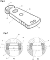
- Figure 4 shows a top view of corresponding different, possible shapes of the gas selector 4 with two adjustment options each; the option for providing one or more notches 21 as well as the indentations 17, which interact with the catch element 7, can be clearly seen.
- the recesses 17 merge, which indicates that no flat surface is formed normally to the movement direction of the catch 7, and the catch 7 is thus always pushed into one of the recesses 17 by the spring 8, so that it is reliably prevented that the gas selector 4 is brought into an inactive intermediate position. If this should take place, the catch 7, due to the effect of the catch spring 8, will push the gas selector 4 into one of the two possible “correct” positions.
- Figure 5 shows a perspective view of a possible shape of the gas selector. It can be clearly seen that, due to the approximately central position of the rotational axis--the axial bore 19 between the front and the rear end of the selector 4--a pushing actuation is possible even if the end of the selector with the gas through-bores 20 is pushed into the gas block 3 all the way to the stop, and so a gripping and (one-handed) pressing from the other side of the weapon is possible, but not necessary.
- a cartridge In the initial state, a cartridge is located in the cartridge chamber (not depicted) of the barrel 1. After firing a shot, the projectile, driven by the gas pressure of the propellant charge, moves in the barrel bore 2 in the direction of the muzzle. After the projectile has passed the gas removal bore 13, shown in Figure 6 , a portion of the combustion gases, generated by the combustion process of the propellant charge, flows through the gas removal bore 13 into the corresponding lower gas bore 24 ( Figure 3 ) of the gas block 3 with the sealing sleeve 11, through the gas through-bore 20 of the gas selector 4, through the upper gas bore 23 of the gas block 3 and continues through the gas pipe bore 22 into the interior of the gas pipe 5.
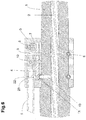
- Figure 6 shows the entire structure of an adjustment device according to the invention as a sectional view through the weapon median plane: From the barrel 1, the gas removal hole 13 branches off and opens into the gas block 3 in a lower gas bore 24 ( Figure 3 ). In said gas bore, a sealing sleeve 11 is inserted, the operating principle of which shall be explained below with reference to Figure 7 .
- One of the gas through-bores of the selector 4 also simply called a platelet, is arranged in alignment with the lower gas bore; the upper gas bore 23, which opens into the gas bore 22 of the gas pipe 5, is arranged above. Said platelet is inserted with its front end deep into a seat of the selector 4 and secured by a gas pipe retaining pin 12 running normally to the weapon median plane.
- the gas pipe 5 is closed in this area by means of a plug which also contributes to the mechanical robustness in the area of the pin 12.
- a recess preferably a bore, which runs normally to the barrel 1 in the weapon median plane, and in which the catch element 7 is slidably mounted and pushed under the effect of a catch element spring 8 toward the selector 4.
- the tip of the catch element is preferably designed to be conical, with a rounded tip, in order to be able to interact in the best possible manner with the recesses of the catch positions 17.
- the pivot pin 9 and the stop pin 10 are mounted in two through-bores, which, in the depicted embodiment, are held in this manner, on the side of the recess which is at a distance from the barrel and on the side close to the barrel, in the gas block 3 for the selector 4, which is particularly advantageous in case of the dynamic load.
- the gas block 3 as a whole is attached to the barrel with a retaining device 6; by way of example, the drawing shows two holding pins which lie in recesses of the gas block and corresponding transverse grooves of the barrel.
- the different bores are parallel to one another and can thus be produced without reclamping; in addition, with the exception of the seat for the catch 7, they are designed as through-bores, which is also advantageous for the production. It is also possible to design said bores as stepped through-bores , but this requires the use of a spring plate.
- the incrementing of the diameters of the bores 23, 24, as described below, can also be produced without problems.
- the gas flow from the barrel 1 into the gas pipe 5 via the gas block 3 is regulated by selecting differently sized diameters of the at least two gas through-bores 20 of the gas selector 4.
- a small diameter causes a lower gas flow (e.g., for cartridges with a larger propellant charge) and correspondingly, a larger diameter causes a larger gas flow (e.g., for use of cartridges with a smaller propellant charge).
- the gas selector is centrally provided with an axis bore 19; in the installed state, the gas selector 4 is correspondingly pivotable about the pivot axis pin 9 located in the axis bore 19.
- the stop recess 18 and the stop pin 10 lying therein form an internal end stop and delimit the possible pivoting movement.
- Figures 7a and 7b show the circled detail of Figure 6 , the optionally provided sealing sleeve 11, which lies in the lower gas bore 24, in its installation situation (7a) and in the operating state (7b), while gas flows through it.
- Figure 7b shows how, due to the sudden pressure increase, the sealing sleeve is carried along by the gas flow, effecting a sealing of the gap between the gas block 3 and the gas selector 4.
- the gas selector 4 is already sealed off with regard to the gas block 3 because the installation takes place without gaps.
- the inner diameter of the sealing sleeve 11 is at least as large as the diameter of the gas removal bore and tapers toward the top.
- the tapered inner diameter of the sealing sleeve 11 is greater than the diameter of the largest gas through-bore 20 of the gas selector 4.
- the "large" diameter of the sealing sleeve 11 is smaller than or equal to the diameter of the lower gas bore 24.
- the sealing sleeve 11 is lifted up, as shown in Figure 7b , when gas flows from the barrel 1 to the gas pipe 5, closing the gap to the gas selector 4; however, the sealing with regard to the gas block 3 is maintained due to the contact of the jacket of the sealing sleeve with the wall of the lower gas bore 24. Mini gaps occurring in rare cases in the course of unfavorable tolerance accumulations between the gas selector 4 and the upper gas bore 23 are also closed by these measures.
- the invention is not limited to the depicted and described embodiments, but can be modified and developed in multiple ways.
- the notches 21 can have a different shapes and quantities, on its "underside," the gas selector 4 can also have recesses 17 for the catch 7 to allow the user to be able to make the changes in the direction familiar to such user, and so forth.
- the barrel axis and the axis of the gas pipe are usually located in the weapon median plane which, for example, corresponds to the drawing plane in Figure 6 . This is due to the usual structure of a carbine, but it is not important for the structure of the selector according to the invention.
- the invention relates to the following: Carbine having a barrel with a gas removal bore 13 and a gas system, which guides gas selectively from the gas removal bore 13 through a lower gas bore 24 and a matchingly aligned upper gas bore 23 to a gas pipe 5, with a platelet 4, movable between at least two positions in the gas system, in which at least two gas through-bores 20 of different cross-sections are provided, with a catch element 7 which is under the effect of a spring 8 and ensures the selected position of the platelet 4, wherein, in each of the at least two positions of the platelet 4, one of the at least two gas through-bores 20 comes to rest in alignment between the gas bores 23, 24, characterized in that the platelet 4 is pivotable about a pivot axis pin 9, immovably provided in the gas system, the axis of which runs parallel to the axis of the bores 23, 24 and is pivotable; that a stop pin 10, immovably provided in the gas system and parallel to the pivot axis pin 9, pro
Landscapes
- Engineering & Computer Science (AREA)
- General Engineering & Computer Science (AREA)
- Aiming, Guidance, Guns With A Light Source, Armor, Camouflage, And Targets (AREA)
- Filling Or Discharging Of Gas Storage Vessels (AREA)
- Output Control And Ontrol Of Special Type Engine (AREA)
- Fluid-Damping Devices (AREA)
Abstract
Description
- The invention relates to a carbine with an adjustment device for a gas-operated weapon according to the preamble of
claim 1 andUS 8,960,069 B1 cited below. - In automatic firearms, so-called gas-operated weapons, such as in the M4- or AR15-based systems, the automatic reloading process can be gas-powered. In this case, a small portion of the gas used for the propulsion of the projectile is removed during the firing of a shot by means of at least one gas removal bore located in the vicinity of the muzzle and guided via a gas block and a gas pipe in the direction of the lock. The high energy of the gas pressure is used to unlock and open the lock and to eject the empty shell.
- Using different types of ammunition results in different removable gas pressures. In order to ensure the correct unlocking and opening of the lock, the removed gas pressure must be adjusted accordingly by means of a gas pressure control option (= gas selector).
- In the prior art, this is achieved as follows:
- Very widespread are rotatable or screwable gas selectors which are arranged, e.g., at the gas block or also near the lock at the so-called "gas key." For example, by means of different diameters of a bore, the gas selectors can regulate the gas flow flowing through in that the rotational movement of the gas selector places different bores between the gas removal bore and the gas pipe. In some cases, selecting "no hole" can completely interrupt the gas flow, which of course means that the weapon no longer reloads automatically. See, e.g.,
US2015292825A1 , orUS9372038 B1 - For example,
US2017321978 A1 discloses such a screwable gas selector with differently sized bores in the thread, which regulate the gas flow. -
US2016033218A1 discloses a gas selector which is adjustable by means of a tool, such as a screwdriver. - Variations with the gas selector located at the so-called "gas key" are disadvantageous for use in the field because the gas flow of the weapon is adjustable only in the disassembled state.
- These gas selectors are frequently only adjustable by means of a tool, such as a screwdriver. Solutions that allow for an adjustment of the gas selector only by means of tools are particularly disadvantageous for field use because without an appropriate tool, the gas pressure cannot be adjusted.
- However, variations with valves are also possible, e.g.,
WO2016/086191A2 discloses a needle valve for adjusting the gas flow. - Solutions, in which gas selectors are mounted by means of threaded fasteners, preclude economically required low production costs due to the elaborate and expensive production of threads.
- Variations without catch or stop: inadvertent adjustment to "zero flow" equals no automatic reloading; unusable in the field.
- Slider variations have no automatic seal, and the gas flow can escape sideways in an uncontrolled manner.
-
US201615133633A1 US20060065112A1 also discloses a slidable gas selector with a catch but without an end stop. -
US8960069B1 is the prior art closest to the invention, describing a slidable gas selector. - The disclosures of
US 2015/292825 A1 ,US 9,372,038 B1 US 2017/321978 A1 ,US 2016/033218 A1 ,WO2016/086191 A2 ,US 2016/15133633 A1 US 2006/0065112 A1 , andUS 8,960,069 B1 are made part of the content of the present application for the jurisdictions in which this is possible. -
US 8,960,069 B1 discloses a platelet which is slidable transversely to the barrel axis and has two bores which can be alternately aligned with the removal bore in the barrel. A pin, arranged parallel to the barrel axis in the plane of the platelet and pushed by a spring towards the platelet, engages in recesses at the edge of the platelet, thus safely ensuring the position of the platelet without preventing the desired sliding. The sliding, as any sliding without a specific guide, is always threatened by tilting, which greatly impairs the functionality. Notwithstanding the above, the device leaks above and below the platelet with all the associated disadvantages. - For economic reasons, the objective is a most cost-effective production of the firearm and a preferably small number of components. There is thus a need for a gas system with a gas selector which does not have the disadvantages of the prior art but has the properties initially described. The problem addressed by the invention is that of providing a gas system with a gas selector, which is reliable, easy to clean, and easily and reliably adaptable, and in one embodiment is supposed to also be sealed to the greatest possible extent.
- According to the invention, these problems are solved by a gas system of the initially described type, which has the features described in the characterizing part of
claim 1. In other words, including the achievable advantages: - The gas system has a gas selector, which is pivotable about an axis and multi-adjustable, for the tool-free adjustment of the gas pressure forwarded from the barrel in the direction of the gas pipe;
- the pivotable gas selector has a locking system, with which at least two predetermined positions of the gas selector are to be selected, wherein no undefined intermediate position can be set;
- the pivotable gas selector has an end stop and can thus not assume a "too far" position;
- the respective selectable position of the gas selector corresponds to a respective associated gas through-bore with a correspondingly designed diameter in order to adjust the gas flow.
- The solution according to the invention makes it possible to achieve the following advantages:
Due to the inventive pivoting mechanism of the gas selector with a simple structure, a small number of parts are achieved, which do not require a thread and therefore allow for a cost-effective production. - Furthermore, due to the pivotable arrangement of the gas selector, the adjustment of the gas pressure on both sides with one hand (one-handed operation) is made possible without the aid of tools in a quick and simple manner.
- In one embodiment, a special shape of the gas selector with improved haptic surface structure allows for the adjustment of the gas pressure, e.g., in the field in bad weather conditions (cold, wet) and when wearing gloves, for example, with the aid of a cartridge. The improved haptic surface structure acts in a slip-proof manner and can, for example, have the shape of one or more indentations.
- Another aspect of the invention relates to the sealing of the gas system. According to the invention, the gas system can be sealed against unwanted gas loss to the outside by means of a self-sealing sealing sleeve, and according to the invention, the full utilization of the gas pressure is accordingly possible without uncontrolled escape of gas on the side.
- The invention shall be explained in more detail in the drawings using an embodiment.
-
Figure 1 shows a barrel of a carbine with a gas block according to the invention; -
Figure 2 shows a cross-section of the barrel with the gas block ofFigure 1 ; -
Figure 3 shows an exploded view of the gas block with individual components; -
Figures 4a to 4d ) show variations of the gas selector; -
Figure 5 shows a three-dimensional view of a variation of the gas selector; -
Figure 6 shows a cross-section of a gas block; and -
Figures 7a and 7b show detailed views of a sealing sleeve in the gas block. -
Figure 1 shows atypical barrel 1 with thegas block 3 mounted near the muzzle, and agas pipe 5 of a gas-operated weapon.Figure 2 shows a cross-section of the barrel axis of atypical barrel 1 withbarrel bore 2 and gas removal bore 13, via which a gas flow from thebarrel 1 into thegas block 3 and further into thegas pipe 5 is possible. - The
gas block 3, shown in an exploded view inFigure 3 , has abarrel seat 14 for thebarrel 1 and agas pipe seat 15 for thegas pipe 5. By means of aretaining device 6, consisting of two pins in the depicted embodiment, thegas block 3 is fastened to thebarrel 1, and to thegas pipe 5 by means of a gaspipe holding pin 12. - The
gas selector 4 fits into thegas block recess 16 provided for this purpose and is pivotably mounted in the gas block by means of apivot axis pin 9, wherein the pivoting movement is delimited by astop pin 10. Acatch element 7 with acatch spring 8 effects an automatic meshing of thegas selector 4 at one of the at least two predetermined options of the pivoting movement. Optionally, asealing sleeve 11 lying in alower gas bore 24 is provided, which shall be explained in more detail below. - The gas selector can be actuated without tools and with one hand on both sides. It can have one or more improved haptic surface structurings 21 to allow for an adjustment without slippage, for example, using a cartridge as a "tool." The improved haptic surface structuring 21 is shown as an anti-slip notch, in which, for example, the projectile side of a cartridge engages. This is advantageous particularly when used in the field in adverse weather conditions (e.g., cold, wet) and when using gloves.
- By way of example,
Figure 4 shows a top view of corresponding different, possible shapes of thegas selector 4 with two adjustment options each; the option for providing one ormore notches 21 as well as theindentations 17, which interact with thecatch element 7, can be clearly seen. As can be clearly seen, therecesses 17 merge, which indicates that no flat surface is formed normally to the movement direction of thecatch 7, and thecatch 7 is thus always pushed into one of therecesses 17 by thespring 8, so that it is reliably prevented that thegas selector 4 is brought into an inactive intermediate position. If this should take place, thecatch 7, due to the effect of thecatch spring 8, will push thegas selector 4 into one of the two possible "correct" positions. - The two gas through-
bores 20 with different diameters can be clearly seen inFigure 4 , as well as theaxial bore 19, with which thegas selector 4 rotates about thepivot axis pin 9, and the stop bore 18, actually a curved elongated hole which, through interaction with thestop pin 10, delimits the pivoting movement of thegas selector 4 about thepivot axis pin 9. -
Figure 5 shows a perspective view of a possible shape of the gas selector. It can be clearly seen that, due to the approximately central position of the rotational axis--theaxial bore 19 between the front and the rear end of theselector 4--a pushing actuation is possible even if the end of the selector with the gas through-bores 20 is pushed into thegas block 3 all the way to the stop, and so a gripping and (one-handed) pressing from the other side of the weapon is possible, but not necessary. - The functional principle according to the invention can be summarized as follows:
In the initial state, a cartridge is located in the cartridge chamber (not depicted) of thebarrel 1. After firing a shot, the projectile, driven by the gas pressure of the propellant charge, moves in the barrel bore 2 in the direction of the muzzle. After the projectile has passed the gas removal bore 13, shown inFigure 6 , a portion of the combustion gases, generated by the combustion process of the propellant charge, flows through the gas removal bore 13 into the corresponding lower gas bore 24 (Figure 3 ) of thegas block 3 with the sealingsleeve 11, through the gas through-bore 20 of thegas selector 4, through the upper gas bore 23 of thegas block 3 and continues through the gas pipe bore 22 into the interior of thegas pipe 5. -
Figure 6 shows the entire structure of an adjustment device according to the invention as a sectional view through the weapon median plane: From thebarrel 1, thegas removal hole 13 branches off and opens into thegas block 3 in a lower gas bore 24 (Figure 3 ). In said gas bore, a sealingsleeve 11 is inserted, the operating principle of which shall be explained below with reference toFigure 7 . One of the gas through-bores of theselector 4, also simply called a platelet, is arranged in alignment with the lower gas bore; the upper gas bore 23, which opens into the gas bore 22 of thegas pipe 5, is arranged above. Said platelet is inserted with its front end deep into a seat of theselector 4 and secured by a gaspipe retaining pin 12 running normally to the weapon median plane. In order to avoid undesired gas leakage toward the front, thegas pipe 5 is closed in this area by means of a plug which also contributes to the mechanical robustness in the area of thepin 12. - In the front area of the
gas block 3, a recess, preferably a bore, is provided which runs normally to thebarrel 1 in the weapon median plane, and in which thecatch element 7 is slidably mounted and pushed under the effect of acatch element spring 8 toward theselector 4. The tip of the catch element is preferably designed to be conical, with a rounded tip, in order to be able to interact in the best possible manner with the recesses of the catch positions 17. Thepivot pin 9 and thestop pin 10 are mounted in two through-bores, which, in the depicted embodiment, are held in this manner, on the side of the recess which is at a distance from the barrel and on the side close to the barrel, in thegas block 3 for theselector 4, which is particularly advantageous in case of the dynamic load. - The
gas block 3 as a whole is attached to the barrel with a retainingdevice 6; by way of example, the drawing shows two holding pins which lie in recesses of the gas block and corresponding transverse grooves of the barrel. - In the
gas block 3, as can also be clearly seen inFigure 6 , the different bores are parallel to one another and can thus be produced without reclamping; in addition, with the exception of the seat for thecatch 7, they are designed as through-bores, which is also advantageous for the production. It is also possible to design said bores as stepped through-bores , but this requires the use of a spring plate. The incrementing of the diameters of thebores - The gas flow from the
barrel 1 into thegas pipe 5 via thegas block 3 is regulated by selecting differently sized diameters of the at least two gas through-bores 20 of thegas selector 4. A small diameter causes a lower gas flow (e.g., for cartridges with a larger propellant charge) and correspondingly, a larger diameter causes a larger gas flow (e.g., for use of cartridges with a smaller propellant charge). The gas selector is centrally provided with an axis bore 19; in the installed state, thegas selector 4 is correspondingly pivotable about thepivot axis pin 9 located in the axis bore 19. Thestop recess 18 and thestop pin 10 lying therein form an internal end stop and delimit the possible pivoting movement. According to the number of gas through-bores 20, there are at least twocatch positions 17 which, in the installed state, each individually align the respective associated gas through-bore 20 in one line with the gas removal bore 13 of the lower gas bore 24 and the upper gas bore 23, thus allowing for the gas flow through the respective gas through-bore 20 with the appropriate diameter. -
Figures 7a and 7b show the circled detail ofFigure 6 , the optionally provided sealingsleeve 11, which lies in the lower gas bore 24, in its installation situation (7a) and in the operating state (7b), while gas flows through it.Figure 7b shows how, due to the sudden pressure increase, the sealing sleeve is carried along by the gas flow, effecting a sealing of the gap between thegas block 3 and thegas selector 4. - Toward the top, the
gas selector 4 is already sealed off with regard to thegas block 3 because the installation takes place without gaps. - The inner diameter of the sealing
sleeve 11 is at least as large as the diameter of the gas removal bore and tapers toward the top. The tapered inner diameter of the sealingsleeve 11 is greater than the diameter of the largest gas through-bore 20 of thegas selector 4. The "large" diameter of the sealingsleeve 11 is smaller than or equal to the diameter of the lower gas bore 24. - Due to these measures, the sealing
sleeve 11 is lifted up, as shown inFigure 7b , when gas flows from thebarrel 1 to thegas pipe 5, closing the gap to thegas selector 4; however, the sealing with regard to thegas block 3 is maintained due to the contact of the jacket of the sealing sleeve with the wall of the lower gas bore 24. Mini gaps occurring in rare cases in the course of unfavorable tolerance accumulations between thegas selector 4 and the upper gas bore 23 are also closed by these measures. - For the assembly, it shall only be described briefly, with reference to
Figure 6 , that thespring 8, together with thecatch 7, is introduced first into its seat, followed by the insertion of theselector 4 into the slot of thegas block 3, wherein the sealingsleeve 11 is optionally inserted beforehand in the lower gas bore 24, followed by the insertion of thepins gas pipe 5 is appropriately threaded, and thepins pins sleeve 11. - The invention is not limited to the depicted and described embodiments, but can be modified and developed in multiple ways. For example, particularly three or more gas through-
bores 20 with different diameters can be provided, thenotches 21 can have a different shapes and quantities, on its "underside," thegas selector 4 can also haverecesses 17 for thecatch 7 to allow the user to be able to make the changes in the direction familiar to such user, and so forth. - In the description, as in the prior art, reference is made to the different diameters of the gas through-
bores 20; in reality, the different cross-sections of these bores are important. - All materials already used in the prior art can be taken into consideration as the materials for the gas selector, the pins, and the spring; a person skilled in the art can select them with the knowledge of the expected stress.
- The barrel axis and the axis of the gas pipe are usually located in the weapon median plane which, for example, corresponds to the drawing plane in
Figure 6 . This is due to the usual structure of a carbine, but it is not important for the structure of the selector according to the invention. - In summary, it can be noted that the invention relates to the following: Carbine having a barrel with a gas removal bore 13 and a gas system, which guides gas selectively from the gas removal bore 13 through a lower gas bore 24 and a matchingly aligned upper gas bore 23 to a gas pipe 5, with a platelet 4, movable between at least two positions in the gas system, in which at least two gas through-bores 20 of different cross-sections are provided, with a catch element 7 which is under the effect of a spring 8 and ensures the selected position of the platelet 4, wherein, in each of the at least two positions of the platelet 4, one of the at least two gas through-bores 20 comes to rest in alignment between the gas bores 23, 24, characterized in that the platelet 4 is pivotable about a pivot axis pin 9, immovably provided in the gas system, the axis of which runs parallel to the axis of the bores 23, 24 and is pivotable; that a stop pin 10, immovably provided in the gas system and parallel to the pivot axis pin 9, protrudes into a stop bore 18 of the platelet 4, thus delimiting the pivoting; that the platelet 4 has at least two recessed catch positions 17, into which a catch 7, under the effect of a catch spring 8, optionally engages, provided that the gas through-bore 20 associated with the catch 7 comes to rest in alignment between the gas bores 23, 24 when the catch 7 engages in one of the recesses.
List of reference signs: 1 Barrel 13 Gas removal bore 2 Barrel bore 14 Barrel seat 3 Gas block 15 Gas pipe seat 4 Gas selector, platelet 16 Recess 5 Gas pipe 17 Catch position 6 Retaining device 18 Stop bore 7 Catch element (for gas selector) 19 Axis bore 8 Catch element spring 20 Gas through- bore 9 Pivot axis pin 21 Anti-slip notch 10 Stop pin 22 Gas pipe bore 11 Sealing sleeve 23 Upper gas bore 12 Gas pipe holding pin 24 Lower gas bore
Claims (4)
- Carbine having a barrel with a gas removal bore (13) and a gas system, which guides gas selectively from the gas removal bore (13) through a lower gas bore (24) and a matchingly aligned upper gas bore (23) to a gas pipe (5), with a platelet (4), movable between at least two positions in the gas system, in which at least two gas through-bores (20) of different cross-sections are provided, with a catch element (7) which is under the effect of a spring (8) and ensures the selected position of the platelet (4), wherein, in each of the at least two positions of the platelet (4), one of the at least two gas through-bores (20) comes to rest in alignment between the gas bores (23, 24), characterized in that the platelet (4) is pivotable about a pivot axis pin (9), immovably provided in the gas system, the axis of which runs parallel to the axis of the bores (23, 24) and is pivotable; that a stop pin (10), immovably provided in the gas system and parallel to the pivot axis pin (9), protrudes into a stop bore (18) of the platelet (4), thus delimiting the pivoting; that the platelet (4) has at least two recessed catch positions (17), into which a catch (7), under the effect of a catch spring (8), optionally engages, provided that the gas through-bore (20) associated with the catch (7) comes to rest in alignment between the gas bores (23, 24) when the catch (7) engages in one of the recesses.
- Carbine according to claim 1, characterized in that adjacent recessed catch positions (17) merge into one another.
- Carbine according to claim 1 or 2, characterized in that the platelet (4) is provided on its outline with at least one anti-slip notch (21).
- Carbine according to claim 3, characterized in that the at least one anti-slip notch (21) corresponds geometrically to the projectile side of a cartridge designed for the carbine.
Priority Applications (3)
| Application Number | Priority Date | Filing Date | Title |
|---|---|---|---|
| EP19201447.0A EP3800425B1 (en) | 2019-10-04 | 2019-10-04 | Carbine with an adjustment device for gas-operated weapons |
| HRP20220950TT HRP20220950T1 (en) | 2019-10-04 | 2019-10-04 | Carbine with an adjustment device for gas-operated weapons |
| US17/061,784 US11118853B2 (en) | 2019-10-04 | 2020-10-02 | Gas-operated firearm with adjustable gas pressure selector |
Applications Claiming Priority (1)
| Application Number | Priority Date | Filing Date | Title |
|---|---|---|---|
| EP19201447.0A EP3800425B1 (en) | 2019-10-04 | 2019-10-04 | Carbine with an adjustment device for gas-operated weapons |
Publications (2)
| Publication Number | Publication Date |
|---|---|
| EP3800425A1 true EP3800425A1 (en) | 2021-04-07 |
| EP3800425B1 EP3800425B1 (en) | 2022-05-18 |
Family
ID=68158923
Family Applications (1)
| Application Number | Title | Priority Date | Filing Date |
|---|---|---|---|
| EP19201447.0A Active EP3800425B1 (en) | 2019-10-04 | 2019-10-04 | Carbine with an adjustment device for gas-operated weapons |
Country Status (3)
| Country | Link |
|---|---|
| US (1) | US11118853B2 (en) |
| EP (1) | EP3800425B1 (en) |
| HR (1) | HRP20220950T1 (en) |
Cited By (1)
| Publication number | Priority date | Publication date | Assignee | Title |
|---|---|---|---|---|
| EP4166893A1 (en) * | 2021-10-15 | 2023-04-19 | Heckler & Koch GmbH | Gas take off |
Families Citing this family (2)
| Publication number | Priority date | Publication date | Assignee | Title |
|---|---|---|---|---|
| US11680762B2 (en) * | 2020-12-21 | 2023-06-20 | Caracal International, Llc | Firearm with adjustable gas block regulator |
| US20240377150A1 (en) * | 2023-05-12 | 2024-11-14 | Polaris Capital Corporation | Adjustable gas regulating systems and apparatuses |
Citations (8)
| Publication number | Priority date | Publication date | Assignee | Title |
|---|---|---|---|---|
| US20060065112A1 (en) | 2004-09-17 | 2006-03-30 | Grzegorz Kuczynko | Firearm having an indirect gas operating system |
| US8960069B1 (en) | 2011-12-13 | 2015-02-24 | MicroMOA, LLC | Adjustable gas block method, system and device for a gas operation firearm |
| US20150292825A1 (en) | 2014-04-15 | 2015-10-15 | Charles B. Cassels | Super & subsonic gas regulator assembly |
| US20160033218A1 (en) | 2014-06-10 | 2016-02-04 | CreativeArms, LLC | Semiautomatic firearm |
| WO2016086191A2 (en) | 2014-11-26 | 2016-06-02 | Gray Michael S | Improved firearm |
| US9372038B1 (en) | 2014-08-11 | 2016-06-21 | Primary Weapons | Adjustable carrier |
| US20170307315A1 (en) * | 2016-04-20 | 2017-10-26 | F-1 Research, Llc - Patents Series | Gas block for a firearm |
| US20170321978A1 (en) | 2016-05-05 | 2017-11-09 | FN America, LLC | Tactical rifle |
Family Cites Families (5)
| Publication number | Priority date | Publication date | Assignee | Title |
|---|---|---|---|---|
| US8393259B2 (en) * | 2009-10-26 | 2013-03-12 | Mark C. LaRue | Firearm barrel having multiple ports and port selector |
| US8596185B1 (en) * | 2011-12-13 | 2013-12-03 | MicroMOA, LLC | Adjustable gas block method, system and device for a gas operation firearm |
| US9335106B1 (en) * | 2014-12-23 | 2016-05-10 | Smith & Wesson Corp. | Adjustable gas block |
| US10330409B2 (en) * | 2017-01-17 | 2019-06-25 | Ernest R. Bray | Worm drive gas regulator |
| US20210055067A1 (en) * | 2019-08-20 | 2021-02-25 | Fortis Manufacturing, Inc. | Adjustable gas block for a firearm |
-
2019
- 2019-10-04 HR HRP20220950TT patent/HRP20220950T1/en unknown
- 2019-10-04 EP EP19201447.0A patent/EP3800425B1/en active Active
-
2020
- 2020-10-02 US US17/061,784 patent/US11118853B2/en active Active
Patent Citations (8)
| Publication number | Priority date | Publication date | Assignee | Title |
|---|---|---|---|---|
| US20060065112A1 (en) | 2004-09-17 | 2006-03-30 | Grzegorz Kuczynko | Firearm having an indirect gas operating system |
| US8960069B1 (en) | 2011-12-13 | 2015-02-24 | MicroMOA, LLC | Adjustable gas block method, system and device for a gas operation firearm |
| US20150292825A1 (en) | 2014-04-15 | 2015-10-15 | Charles B. Cassels | Super & subsonic gas regulator assembly |
| US20160033218A1 (en) | 2014-06-10 | 2016-02-04 | CreativeArms, LLC | Semiautomatic firearm |
| US9372038B1 (en) | 2014-08-11 | 2016-06-21 | Primary Weapons | Adjustable carrier |
| WO2016086191A2 (en) | 2014-11-26 | 2016-06-02 | Gray Michael S | Improved firearm |
| US20170307315A1 (en) * | 2016-04-20 | 2017-10-26 | F-1 Research, Llc - Patents Series | Gas block for a firearm |
| US20170321978A1 (en) | 2016-05-05 | 2017-11-09 | FN America, LLC | Tactical rifle |
Cited By (2)
| Publication number | Priority date | Publication date | Assignee | Title |
|---|---|---|---|---|
| EP4166893A1 (en) * | 2021-10-15 | 2023-04-19 | Heckler & Koch GmbH | Gas take off |
| US12188738B2 (en) | 2021-10-15 | 2025-01-07 | Heckler &Koch Gmbh | Gas block for automatic firearms |
Also Published As
| Publication number | Publication date |
|---|---|
| US20210222975A1 (en) | 2021-07-22 |
| EP3800425B1 (en) | 2022-05-18 |
| US11118853B2 (en) | 2021-09-14 |
| HRP20220950T1 (en) | 2022-10-28 |
Similar Documents
| Publication | Publication Date | Title |
|---|---|---|
| EP3800425B1 (en) | Carbine with an adjustment device for gas-operated weapons | |
| US8393259B2 (en) | Firearm barrel having multiple ports and port selector | |
| US9857129B1 (en) | Gas adjustment system for a firearm bolt carrier | |
| EP1797389B1 (en) | Firearm having an indirect gas operating system | |
| US4125054A (en) | Mechanism for gas control in an automatic firearm | |
| US20230228507A1 (en) | Adjustable gas valve for firearm | |
| US9103610B2 (en) | Tool-less variable gas block | |
| US20120279381A1 (en) | Locking device for movable momentum connection in suppressors for semi-automatic and fully automatic weapons | |
| US10041751B2 (en) | Rotary lockup action | |
| KR20090043503A (en) | Gun degassing structures, gun components, and weapons | |
| US10222151B2 (en) | Regulator for a firearm auto loader | |
| US10557675B1 (en) | Devices for restricting the flow of propellant gas in gas-actuated firearms | |
| US11118852B2 (en) | Gas-powered firearm | |
| US7448372B2 (en) | Shooting structure of a paint bullet gun | |
| US9803941B2 (en) | Adjustable gas system for cartridge gas actuated firearms | |
| US11215414B2 (en) | Firearm with gas-operated reloading | |
| US20170307315A1 (en) | Gas block for a firearm | |
| US5952602A (en) | Precision device for hand guns | |
| RU176270U1 (en) | ADJUSTABLE GAS BLOCK FOR FIREARMS | |
| KR102896483B1 (en) | Gas block | |
| GB2439798A (en) | Shooting structure of a paint ball gun | |
| WO2019172771A2 (en) | A bolt action system, a firearm and a bolt action system operating method | |
| RU2019113903A (en) | METHOD FOR OPERATION OF SLEEVELESS AUTOMATIC WEAPON WITH BALANCED AUTOMATION AND RELEASE FORCE COMPENSATION MECHANISM, DEVICE FOR ITS IMPLEMENTATION AND METHOD FOR PAIRING THE OPERATION OF THE DEVICE WITH THE CARRIER |
Legal Events
| Date | Code | Title | Description |
|---|---|---|---|
| REG | Reference to a national code |
Ref country code: HR Ref legal event code: TUEP Ref document number: P20220950 Country of ref document: HR |
|
| PUAI | Public reference made under article 153(3) epc to a published international application that has entered the european phase |
Free format text: ORIGINAL CODE: 0009012 |
|
| STAA | Information on the status of an ep patent application or granted ep patent |
Free format text: STATUS: THE APPLICATION HAS BEEN PUBLISHED |
|
| AK | Designated contracting states |
Kind code of ref document: A1 Designated state(s): AL AT BE BG CH CY CZ DE DK EE ES FI FR GB GR HR HU IE IS IT LI LT LU LV MC MK MT NL NO PL PT RO RS SE SI SK SM TR |
|
| AX | Request for extension of the european patent |
Extension state: BA ME |
|
| STAA | Information on the status of an ep patent application or granted ep patent |
Free format text: STATUS: REQUEST FOR EXAMINATION WAS MADE |
|
| 17P | Request for examination filed |
Effective date: 20211007 |
|
| RBV | Designated contracting states (corrected) |
Designated state(s): AL AT BE BG CH CY CZ DE DK EE ES FI FR GB GR HR HU IE IS IT LI LT LU LV MC MK MT NL NO PL PT RO RS SE SI SK SM TR |
|
| GRAP | Despatch of communication of intention to grant a patent |
Free format text: ORIGINAL CODE: EPIDOSNIGR1 |
|
| STAA | Information on the status of an ep patent application or granted ep patent |
Free format text: STATUS: GRANT OF PATENT IS INTENDED |
|
| RIC1 | Information provided on ipc code assigned before grant |
Ipc: F41A 5/24 20060101ALN20220131BHEP Ipc: F41A 5/28 20060101AFI20220131BHEP |
|
| INTG | Intention to grant announced |
Effective date: 20220217 |
|
| GRAS | Grant fee paid |
Free format text: ORIGINAL CODE: EPIDOSNIGR3 |
|
| GRAA | (expected) grant |
Free format text: ORIGINAL CODE: 0009210 |
|
| STAA | Information on the status of an ep patent application or granted ep patent |
Free format text: STATUS: THE PATENT HAS BEEN GRANTED |
|
| AK | Designated contracting states |
Kind code of ref document: B1 Designated state(s): AL AT BE BG CH CY CZ DE DK EE ES FI FR GB GR HR HU IE IS IT LI LT LU LV MC MK MT NL NO PL PT RO RS SE SI SK SM TR |
|
| REG | Reference to a national code |
Ref country code: GB Ref legal event code: FG4D |
|
| REG | Reference to a national code |
Ref country code: CH Ref legal event code: EP |
|
| REG | Reference to a national code |
Ref country code: IE Ref legal event code: FG4D |
|
| REG | Reference to a national code |
Ref country code: DE Ref legal event code: R096 Ref document number: 602019015048 Country of ref document: DE |
|
| REG | Reference to a national code |
Ref country code: AT Ref legal event code: REF Ref document number: 1493385 Country of ref document: AT Kind code of ref document: T Effective date: 20220615 |
|
| REG | Reference to a national code |
Ref country code: LT Ref legal event code: MG9D |
|
| REG | Reference to a national code |
Ref country code: NL Ref legal event code: MP Effective date: 20220518 |
|
| REG | Reference to a national code |
Ref country code: HR Ref legal event code: ODRP Ref document number: P20220950 Country of ref document: HR Payment date: 20220927 Year of fee payment: 4 |
|
| REG | Reference to a national code |
Ref country code: HR Ref legal event code: T1PR Ref document number: P20220950 Country of ref document: HR |
|
| PG25 | Lapsed in a contracting state [announced via postgrant information from national office to epo] |
Ref country code: SE Free format text: LAPSE BECAUSE OF FAILURE TO SUBMIT A TRANSLATION OF THE DESCRIPTION OR TO PAY THE FEE WITHIN THE PRESCRIBED TIME-LIMIT Effective date: 20220518 Ref country code: PT Free format text: LAPSE BECAUSE OF FAILURE TO SUBMIT A TRANSLATION OF THE DESCRIPTION OR TO PAY THE FEE WITHIN THE PRESCRIBED TIME-LIMIT Effective date: 20220919 Ref country code: NO Free format text: LAPSE BECAUSE OF FAILURE TO SUBMIT A TRANSLATION OF THE DESCRIPTION OR TO PAY THE FEE WITHIN THE PRESCRIBED TIME-LIMIT Effective date: 20220818 Ref country code: NL Free format text: LAPSE BECAUSE OF FAILURE TO SUBMIT A TRANSLATION OF THE DESCRIPTION OR TO PAY THE FEE WITHIN THE PRESCRIBED TIME-LIMIT Effective date: 20220518 Ref country code: LT Free format text: LAPSE BECAUSE OF FAILURE TO SUBMIT A TRANSLATION OF THE DESCRIPTION OR TO PAY THE FEE WITHIN THE PRESCRIBED TIME-LIMIT Effective date: 20220518 Ref country code: GR Free format text: LAPSE BECAUSE OF FAILURE TO SUBMIT A TRANSLATION OF THE DESCRIPTION OR TO PAY THE FEE WITHIN THE PRESCRIBED TIME-LIMIT Effective date: 20220819 Ref country code: FI Free format text: LAPSE BECAUSE OF FAILURE TO SUBMIT A TRANSLATION OF THE DESCRIPTION OR TO PAY THE FEE WITHIN THE PRESCRIBED TIME-LIMIT Effective date: 20220518 Ref country code: BG Free format text: LAPSE BECAUSE OF FAILURE TO SUBMIT A TRANSLATION OF THE DESCRIPTION OR TO PAY THE FEE WITHIN THE PRESCRIBED TIME-LIMIT Effective date: 20220818 |
|
| PG25 | Lapsed in a contracting state [announced via postgrant information from national office to epo] |
Ref country code: RS Free format text: LAPSE BECAUSE OF FAILURE TO SUBMIT A TRANSLATION OF THE DESCRIPTION OR TO PAY THE FEE WITHIN THE PRESCRIBED TIME-LIMIT Effective date: 20220518 Ref country code: PL Free format text: LAPSE BECAUSE OF FAILURE TO SUBMIT A TRANSLATION OF THE DESCRIPTION OR TO PAY THE FEE WITHIN THE PRESCRIBED TIME-LIMIT Effective date: 20220518 Ref country code: LV Free format text: LAPSE BECAUSE OF FAILURE TO SUBMIT A TRANSLATION OF THE DESCRIPTION OR TO PAY THE FEE WITHIN THE PRESCRIBED TIME-LIMIT Effective date: 20220518 Ref country code: IS Free format text: LAPSE BECAUSE OF FAILURE TO SUBMIT A TRANSLATION OF THE DESCRIPTION OR TO PAY THE FEE WITHIN THE PRESCRIBED TIME-LIMIT Effective date: 20220918 |
|
| PG25 | Lapsed in a contracting state [announced via postgrant information from national office to epo] |
Ref country code: SM Free format text: LAPSE BECAUSE OF FAILURE TO SUBMIT A TRANSLATION OF THE DESCRIPTION OR TO PAY THE FEE WITHIN THE PRESCRIBED TIME-LIMIT Effective date: 20220518 Ref country code: SK Free format text: LAPSE BECAUSE OF FAILURE TO SUBMIT A TRANSLATION OF THE DESCRIPTION OR TO PAY THE FEE WITHIN THE PRESCRIBED TIME-LIMIT Effective date: 20220518 Ref country code: RO Free format text: LAPSE BECAUSE OF FAILURE TO SUBMIT A TRANSLATION OF THE DESCRIPTION OR TO PAY THE FEE WITHIN THE PRESCRIBED TIME-LIMIT Effective date: 20220518 Ref country code: ES Free format text: LAPSE BECAUSE OF FAILURE TO SUBMIT A TRANSLATION OF THE DESCRIPTION OR TO PAY THE FEE WITHIN THE PRESCRIBED TIME-LIMIT Effective date: 20220518 Ref country code: EE Free format text: LAPSE BECAUSE OF FAILURE TO SUBMIT A TRANSLATION OF THE DESCRIPTION OR TO PAY THE FEE WITHIN THE PRESCRIBED TIME-LIMIT Effective date: 20220518 Ref country code: DK Free format text: LAPSE BECAUSE OF FAILURE TO SUBMIT A TRANSLATION OF THE DESCRIPTION OR TO PAY THE FEE WITHIN THE PRESCRIBED TIME-LIMIT Effective date: 20220518 |
|
| REG | Reference to a national code |
Ref country code: DE Ref legal event code: R097 Ref document number: 602019015048 Country of ref document: DE |
|
| PLBE | No opposition filed within time limit |
Free format text: ORIGINAL CODE: 0009261 |
|
| STAA | Information on the status of an ep patent application or granted ep patent |
Free format text: STATUS: NO OPPOSITION FILED WITHIN TIME LIMIT |
|
| PG25 | Lapsed in a contracting state [announced via postgrant information from national office to epo] |
Ref country code: AL Free format text: LAPSE BECAUSE OF FAILURE TO SUBMIT A TRANSLATION OF THE DESCRIPTION OR TO PAY THE FEE WITHIN THE PRESCRIBED TIME-LIMIT Effective date: 20220518 |
|
| 26N | No opposition filed |
Effective date: 20230221 |
|
| PG25 | Lapsed in a contracting state [announced via postgrant information from national office to epo] |
Ref country code: SI Free format text: LAPSE BECAUSE OF FAILURE TO SUBMIT A TRANSLATION OF THE DESCRIPTION OR TO PAY THE FEE WITHIN THE PRESCRIBED TIME-LIMIT Effective date: 20220518 Ref country code: MC Free format text: LAPSE BECAUSE OF FAILURE TO SUBMIT A TRANSLATION OF THE DESCRIPTION OR TO PAY THE FEE WITHIN THE PRESCRIBED TIME-LIMIT Effective date: 20220518 |
|
| REG | Reference to a national code |
Ref country code: CH Ref legal event code: PL |
|
| P01 | Opt-out of the competence of the unified patent court (upc) registered |
Effective date: 20230425 |
|
| PG25 | Lapsed in a contracting state [announced via postgrant information from national office to epo] |
Ref country code: LU Free format text: LAPSE BECAUSE OF NON-PAYMENT OF DUE FEES Effective date: 20221004 |
|
| PG25 | Lapsed in a contracting state [announced via postgrant information from national office to epo] |
Ref country code: LI Free format text: LAPSE BECAUSE OF NON-PAYMENT OF DUE FEES Effective date: 20221031 Ref country code: FR Free format text: LAPSE BECAUSE OF NON-PAYMENT OF DUE FEES Effective date: 20221031 Ref country code: CH Free format text: LAPSE BECAUSE OF NON-PAYMENT OF DUE FEES Effective date: 20221031 |
|
| REG | Reference to a national code |
Ref country code: AT Ref legal event code: UEP Ref document number: 1493385 Country of ref document: AT Kind code of ref document: T Effective date: 20220518 |
|
| REG | Reference to a national code |
Ref country code: HR Ref legal event code: ODRP Ref document number: P20220950 Country of ref document: HR Payment date: 20230921 Year of fee payment: 5 |
|
| PG25 | Lapsed in a contracting state [announced via postgrant information from national office to epo] |
Ref country code: IE Free format text: LAPSE BECAUSE OF NON-PAYMENT OF DUE FEES Effective date: 20221004 |
|
| PG25 | Lapsed in a contracting state [announced via postgrant information from national office to epo] |
Ref country code: CY Free format text: LAPSE BECAUSE OF FAILURE TO SUBMIT A TRANSLATION OF THE DESCRIPTION OR TO PAY THE FEE WITHIN THE PRESCRIBED TIME-LIMIT Effective date: 20220511 |
|
| PG25 | Lapsed in a contracting state [announced via postgrant information from national office to epo] |
Ref country code: MK Free format text: LAPSE BECAUSE OF FAILURE TO SUBMIT A TRANSLATION OF THE DESCRIPTION OR TO PAY THE FEE WITHIN THE PRESCRIBED TIME-LIMIT Effective date: 20220511 Ref country code: HU Free format text: LAPSE BECAUSE OF FAILURE TO SUBMIT A TRANSLATION OF THE DESCRIPTION OR TO PAY THE FEE WITHIN THE PRESCRIBED TIME-LIMIT; INVALID AB INITIO Effective date: 20191004 |
|
| PG25 | Lapsed in a contracting state [announced via postgrant information from national office to epo] |
Ref country code: MT Free format text: LAPSE BECAUSE OF FAILURE TO SUBMIT A TRANSLATION OF THE DESCRIPTION OR TO PAY THE FEE WITHIN THE PRESCRIBED TIME-LIMIT Effective date: 20220511 |
|
| REG | Reference to a national code |
Ref country code: HR Ref legal event code: ODRP Ref document number: P20220950 Country of ref document: HR Payment date: 20240923 Year of fee payment: 6 |
|
| PG25 | Lapsed in a contracting state [announced via postgrant information from national office to epo] |
Ref country code: BG Free format text: LAPSE BECAUSE OF FAILURE TO SUBMIT A TRANSLATION OF THE DESCRIPTION OR TO PAY THE FEE WITHIN THE PRESCRIBED TIME-LIMIT Effective date: 20220518 |
|
| PG25 | Lapsed in a contracting state [announced via postgrant information from national office to epo] |
Ref country code: BG Free format text: LAPSE BECAUSE OF FAILURE TO SUBMIT A TRANSLATION OF THE DESCRIPTION OR TO PAY THE FEE WITHIN THE PRESCRIBED TIME-LIMIT Effective date: 20220518 |
|
| REG | Reference to a national code |
Ref country code: HR Ref legal event code: ODRP Ref document number: P20220950 Country of ref document: HR Payment date: 20250923 Year of fee payment: 7 |
|
| PGFP | Annual fee paid to national office [announced via postgrant information from national office to epo] |
Ref country code: TR Payment date: 20250929 Year of fee payment: 7 Ref country code: IT Payment date: 20250923 Year of fee payment: 7 |
|
| PGFP | Annual fee paid to national office [announced via postgrant information from national office to epo] |
Ref country code: GB Payment date: 20250926 Year of fee payment: 7 Ref country code: BE Payment date: 20250923 Year of fee payment: 7 |
|
| PGFP | Annual fee paid to national office [announced via postgrant information from national office to epo] |
Ref country code: HR Payment date: 20250923 Year of fee payment: 7 |
|
| PGFP | Annual fee paid to national office [announced via postgrant information from national office to epo] |
Ref country code: CZ Payment date: 20250925 Year of fee payment: 7 |
|
| PGFP | Annual fee paid to national office [announced via postgrant information from national office to epo] |
Ref country code: DE Payment date: 20250923 Year of fee payment: 7 |
|
| PGFP | Annual fee paid to national office [announced via postgrant information from national office to epo] |
Ref country code: AT Payment date: 20251020 Year of fee payment: 7 |